READ IT OR WATCH IT
Read instructions or watch easy-to-follow video.
Scan QR code or visit http://bit.ly/2JecLp7
41092
24-HOUR MECHANICAL
IN-WALL TIMER
6
5
4
3
2
1
1
1
1
0
9
8
7
6
5
4
3
2
1
1
1
1
0
9
8
7
T
I
M
E
N
O
W
OFF TIMER ON
OPERATION
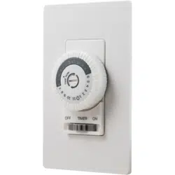
The timer has 3 settings, OFF, TIMER and ON
(See Figure 1).
OFF - Turns connected load off.
TIMER - Connected load turns on and off based
on timer’s settings.
ON - Turns connected load on.
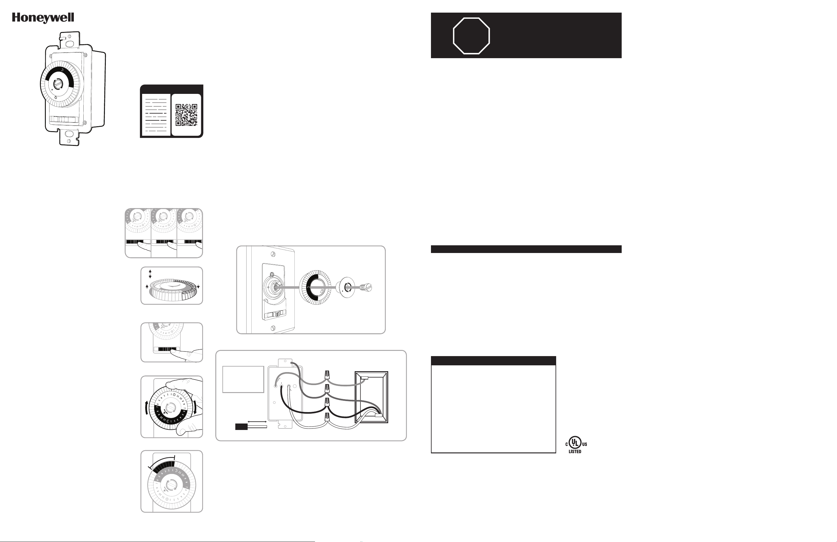
TIMER SETUP
1. The segments around the outer edge of the
timer’s dial represent 30 minute periods. Be sure
all segments are pulled up before programming
(See Figure 2).
2. Place the slide switch in the TIMER position (See
Figure 3).
3. Rotate the timer’s dial clockwise until the pointer
on the face of the dial points to the current time
(See Figure 4). Nighttime hours (from 6:30PM to
6:30AM) are highlighted with a grey background.
4. Select a time period (or periods) you want the
appliance turned on, then push down ALL the
segments that fall on or within that time period. For
example, to have the timer turn an appliance on at
1AM and off at 5AM, push down the segments
representing 1AM and 5AM, and ALL the segments in
between (See Figure 5). You may need to turn the dial
clockwise to access the desired segments. The
setting(s) above the current time setting can not be
moved.
125VAC
15A General/Resistive
1250W Tungsten
1/2HP Motor
500VA Electronic Ballast/LED
Questions? Contact our U.S.-based Consumer Care at 1‑855‑698‑8324,
Monday–Friday, 7AM–8PM CST.
For the most up-to-date product support, accessories, electronic (PDF) format manuals and
more, visit www.byjasco.com/support.
DO NOT RETURN THIS
PRODUCT TO THE STORE
STOP
SPECIFICATIONS
RISK OF ELECTRICAL
SHOCK
• SHUT OFF POWER AT FUSE
BOX OR CIRCUIT BREAKER
BEFORE INSTALLATION
• DO NOT USE IN WET
LOCATIONS
• USE INDOORS ONLY
RISK OF FIRE
• DO NOT USE TO CONTROL
APPLIANCES THAT CONTAIN
HEATING ELEMENTS
(COOKING APPLIANCES,
HEATERS, IRONS, ETC.)
• DO NOT EXCEED
ELECTRICAL RATINGS
• DO NOT USE TO CONTROL
RECEPTACLES
• USE COPPER WIRE ONLY
WITH THIS DEVICE
• CAUTION: HIGH VOLTAGE ‑
DISCONNECT POWER
BEFORE SERVICING.
WARNING
1
1
1
0
9
8
7
6
5
4
3
2
1
1
1
1
0
9
8
7
6
5
4
3
2
1
T
I
M
E
N
O
W
OFF TIMER ON
1
1
1
0
9
8
7
6
5
4
3
2
1
1
1
1
0
9
8
7
6
5
4
3
2
1
T
I
M
E
N
O
W
OFF TIMER ON
1
1
1
0
9
8
7
6
5
4
3
2
1
1
1
1
0
9
8
7
6
5
4
3
2
1
T
I
M
E
N
O
W
OFF TIMER ON
Slide switch to
OFF position
Slide switch to
TIMER position
Slide switch to
ON position
1
1
1
0
9
8
7
6
5
4
3
2
1
1
1
1
0
9
8
7
6
5
4
3
2
1
T
I
M
E
N
O
W
OFF TIMER ON
The Honeywell Trademark is used under license from Honeywell International Inc.
Honeywell International Inc. makes no representation or warranties with respect to this product.
This product is manufactured by Jasco Products Company LLC.
This Jasco product comes with a 2-year limited warranty. Visit www.byjasco.com for warranty details.
MADE IN CHINA/HECHO EN CHINA
©JASCO 2019 | 41092 | 06/12/19 v1
Jasco Products Company LLC.
10 E. Memorial Road
Oklahoma City, OK 73114
Segments up = Device off
Segments down = Device on
Figure 2
Be sure all segments are pulled up
before programming.
OFF TIMER ON
1
1
1
0
9
8
7
6
5
4
3
2
1
1
1
1
0
9
8
7
6
5
4
3
2
1
T
I
M
E
N
O
W
Figure 4
Rotate timer’s dial clockwise.
Figure 3
Slide switch to TIMER position.
Figure 1
OFF TIMER ON
1
1
1
0
9
8
7
6
5
4
3
2
1
1
1
1
0
9
8
7
6
5
4
3
2
1
T
I
M
E
N
O
W
Figure 5
Timer is set to turn on at 1:00AM
and off at 5:00AM. Timer shows
10:00PM time of day.
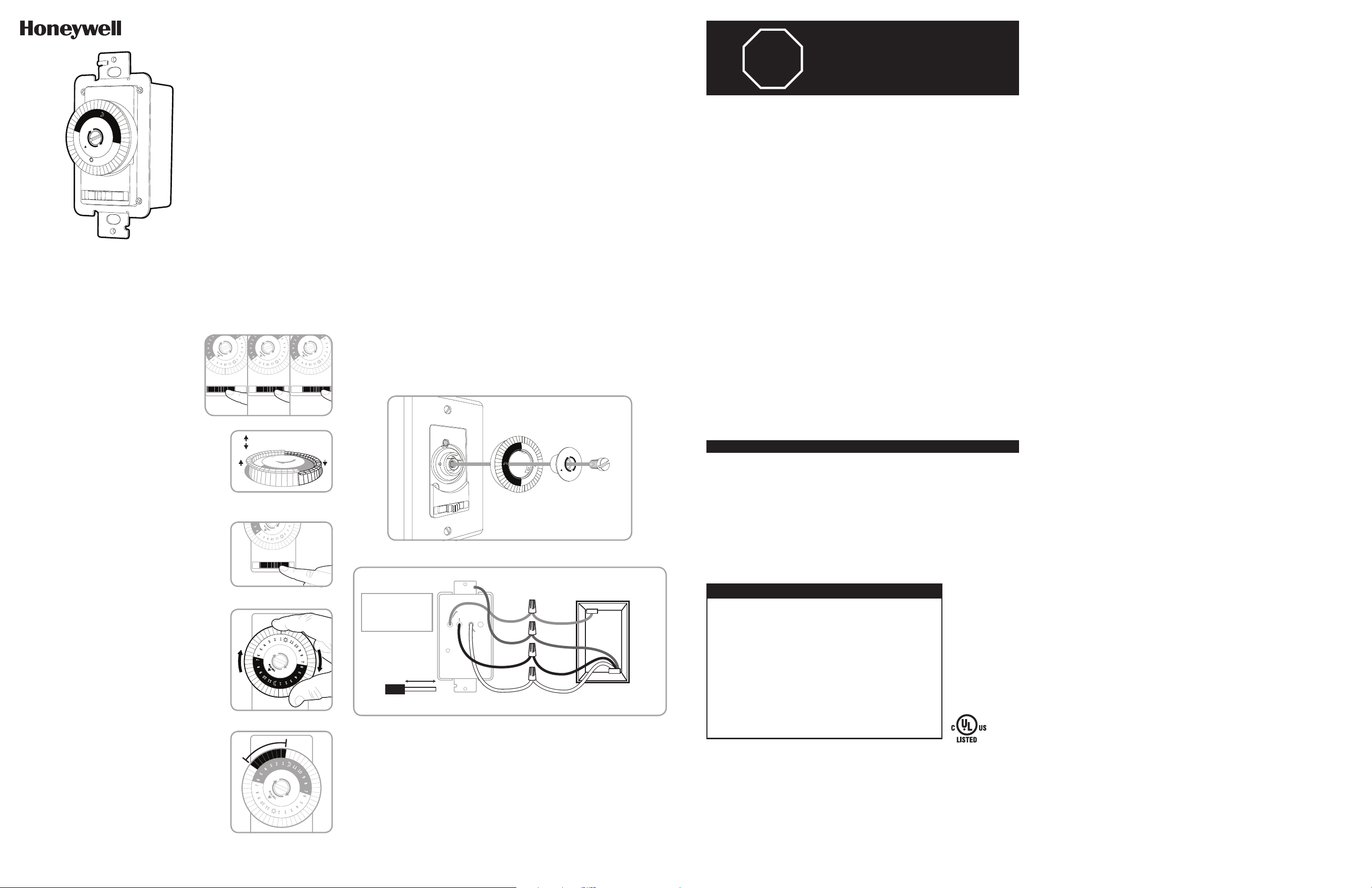
INSTALLATION
Note: If you are unsure or unclear about this installation or if the wires in your box do
not match the manual (not all switch boxes have neutral wires), contact a qualified,
licensed electrician.
1. Using a dime, gently turn the center screw counter-clockwise. Remove the center
screw, center and timer dial. (See Figure 6).
2. Turn OFF the main power at the circuit breaker or fuse box.
3. Remove the existing switch.
4. Connect the timer to the wall box wires with included wire nutes as shown in Figure 7.
a) Connect the hot/live line wire to the hot wire (black).
b) Connect the load wire to the load wire (red).
c) Connect the ground wire to the copper/bare ground wire.
d) Connect the neutral wire to the neutral wire (white). Often the neutral wire can be
found in the back of the wire box connected with a wire nut. There may be several
neutral wires bound together. Add the timer neutral wire to the other neutral wires,
and secure with a wire nut. If needed, use the included jumper.
5. Tuck the wires into the wall box, leaving room for the timer.
6. Use the supplied screws to mount the timer to the wall box, being careful not to crush
any wires.
7. Reinstall your wallplate.Reinstall timer dial and center.
8. Turn the main power on at the circuit breaker.
9. If the timer does not turn on, disconnect the power at the circuit breaker or fuse box.
Swap the line and load wires on the timer. Remount the timer and wallplate, then
restore power at the fuse box or circuit breaker.
OFF
TIMER
ON
6
5
4
3
2
1
1
1
1
0
9
8
7
6
5
4
3
2
1
1
1
1
0
9
8
7
T
I
M
E
N
O
W
Figure 6
Load (Red)
Hot (Black)
Neutral (White)
TIMER
WALL BOX
Line
Neutral
Load
5/8in. (1.6cm)
Wire strip length
WIRE
Ground
Line - Black
Load - Black
Neutral - White
Ground - Green
or Bare
Figure 7 - Connecting the timer wires
41092
TEMPORIZADOR DE PARED
MECÁNICO DE 24 HORAS
6
5
4
3
2
1
1
1
1
0
9
8
7
6
5
4
3
2
1
1
1
1
0
9
8
7
T
I
M
E
N
O
W
OFF TIMER ON
FUNCIONAMIENTO
El temporizador tiene 3 configuraciones,
APAGADO (OFF), TEMPORIZADOR (TIMER)
y ENCENDIDO (ON) (Ver Figura 1).
APAGADO - Apaga la carga conectada.
TEMPORIZADOR - La carga conectada se
enciende y apaga en base a las configuraciones
del temporizador.
ENCENDIDO - Enciende la carga conectada.
CONFIGURACIÓN DEL TEMPORIZADOR
1. Los segmentos alrededor del borde exterior del
dial del temporizador representan periodos de
30 minutos. Asegúrese de que todos los
segmentos estén levantados antes de comenzar
la programación (Ver Figura 2).
2. Coloque el interruptor deslizante en la posición
TEMPORIZADOR (Ver Figura 3).
3. Gire el dial del temporizador hacia la derecha
hasta que la manecilla indique la hora actual
(Ver Figura 4). Las horas nocturnas (de 6:30 p. m.
a 6:30 a. m.) aparecen resaltadas con un fondo gris.
4. Seleccione un periodo (o varios) en que desee que
el aparato esté encendido, luego hunda TODOS los
segmentos que corresponden a ese período. Por
ejemplo, para que el temporizador encienda un
aparato a la 1 a.m. y lo apague a las 5 a.m., hunda
los segmentos que correspondan a la 1 a.m. y a
las 5 a.m. y TODOS los segmentos intermedios
(ver Figura 5). Puede que necesite girar el dial a la
derecha para acceder a los segmentos deseados.
Las configuraciones por encima del horario actual
configurado no pueden moverse.
125 VCA
15A General/resistiva
1250 W tungsteno
Motor de 1/2 HP
500 VA estabilizador electrónico/LED
¿Preguntas? Comuníquese con nuestro Centro de atención al cliente con sede en EE. UU. al
1‑855‑698‑8324, de lunes a viernes, de 7:00 a. m. a 8:00 p. m. CST (hora central estándar).
Para recibir el soporte técnico más actualizado sobre productos, accesorios, manuales en
formato digital (PDF), entre otros, visite www.byjasco.com/support
ESPECIFICACIONES
RIESGO DE DESCARGA
ELÉCTRICA
• INTERRUMPA EL SUMINISTRO
ELÉCTRICO DESDE EL PANEL
DE FUSIBLES O EL DISYUNTOR
ANTES DE PROCEDER A LA
INSTALACIÓN.
• NO UTILICE EN LUGARES
HÚMEDOS
• SOLO PARA USO EN INTERIORES
RIESGO DE INCENDIO
• NO UTILICE PARA CONTROLAR
APARATOS QUE INCLUYAN
RESISTENCIAS ELÉCTRICAS
(APARATOS DE COCCIÓN,
CALEFACTORES, PLANCHAS, ETC.)
• NO SUPERE LOS VALORES
NOMINALES ELÉCTRICOS.
• NO UTILICE EL DISPOSITIVO PARA
CONTROLAR TOMACORRIENTES
• USE SOLO CABLES DE COBRE
CON ESTE DISPOSITIVO.
• PRECAUCIÓN: ALTO VOLTAJE ‑
DESCONECTE EL SUMINISTRO
ELÉCTRICO ANTES DE REALIZAR
EL MANTENIMIENTO.
ADVERTENCIA
1
1
1
0
9
8
7
6
5
4
3
2
1
1
1
1
0
9
8
7
6
5
4
3
2
1
T
I
M
E
N
O
W
OFF TIMER ON
Segmentos levantados =
Dispositivo apagado
Segmentos hundidos =
Dispositivo encendido
Figura 2
Asegúrese de que todos los
segmentos estén levantados antes
de comenzar la programación.
OFF TIMER ON
1
1
1
0
9
8
7
6
5
4
3
2
1
1
1
1
0
9
8
7
6
5
4
3
2
1
T
I
M
E
N
O
W
Figura 4
Gire el dial del temporizador
a la derecha.
Figura 3
Deslice el interruptor a la posición
TEMPORIZADOR.
Figura 1
OFF TIMER ON
1
1
1
0
9
8
7
6
5
4
3
2
1
1
1
1
0
9
8
7
6
5
4
3
2
1
T
I
M
E
N
O
W
Figura 5
El temporizador se encenderá
a la 1 a.m. y se apagará a las
5:00 a.m. El temporizador indica
que son las 10.00 p.m.
INSTALACIÓN
Nota: si no está seguro o duda acerca de esta instalación o si los cables de la caja que
usará no coinciden con el manual (no todas las cajas de interruptores tienen cables
neutros), comuníquese con un electricista calificado con licencia.
1. Gire con cuidado el tornillo central hacia la izquierda con una moneda. Retire el
tornillo central, el centro y el dial del temporizador. (Ver Figura 6).
2. Interrumpa la corriente principal al disyuntor o panel de fusibles.
3. Retire el interruptor existente.
4. Conecte el temporizador a los cables de la caja de embutir con los empalmes de
cable, como se muestra en la Figura 7.
a) Conecte el cable vivo/con corriente línea (line) al cable vivo (negro).
b) Conecte el cable carga (load) al cable carga (rojo).
c) Conecte el cable tierra (ground) al cable tierra cobre/pelado.
d) Conecte el cable neutro (neutral) al cable neutro (blanco). Muchas veces, el cable
neutro se puede encontrar en la parte trasera de la caja de embutir conectado con
un empalme de cable. Puede haber varios cables neutros amarrados. Incluya el cable
neutro del temporizador a los otros cables neutros y asegúrelo con un empalme de
cable. De ser necesario, use el cable del puente incluido.
5. Introduzca los cables en la caja de embutir, dejando espacio para el temporizador.
6. Use los tornillos provistos para instalar el temporizador en la caja de embutir,
teniendo cuidado de no apretar los cables.
7. Vuelva a instalar la placa de pared, el dial del temporizador y el centro.
8. Restablezca la corriente principal en el disyuntor.
9. Si el temporizador no enciende, desconecte el suministro eléctrico en el disyuntor o
panel de fusibles. Intercambie los cables línea y carga en el temporizador. Vuelva a
montar el temporizador y la placa de pared; luego, restablezca el suministro eléctrico
en el disyuntor o panel de fusibles.
OFF
TIMER
ON
6
5
4
3
2
1
1
1
1
0
9
8
7
6
5
4
3
2
1
1
1
1
0
9
8
7
T
I
M
E
N
O
W
Figura 6
Load (rojo)
Con corriente (negro)
Neutro
(blanco)
TEMPORIZADOR
CAJA DE EMBUTIR
Line
(Línea)
Neutral
(Neutro)
Load
(Carga)
5/8 pulg. (1,6 cm)
Longitud de cable
sin aislamiento
CABLE
Ground
(Tierra)
Línea (line) - Negro
Load (carga) - Negro
Neutral (neutro) - Blanco
Ground (tierra) - Verde
o pelado
Figura 7 - Cómo conectar los cables del temporizador
NO DEVUELVA ESTE
PRODUCTO A LA TIENDA
¡PARE!
1
1
1
0
9
8
7
6
5
4
3
2
1
1
1
1
0
9
8
7
6
5
4
3
2
1
T
I
M
E
N
O
W
OFF TIMER ON
1
1
1
0
9
8
7
6
5
4
3
2
1
1
1
1
0
9
8
7
6
5
4
3
2
1
T
I
M
E
N
O
W
OFF TIMER ON
1
1
1
0
9
8
7
6
5
4
3
2
1
1
1
1
0
9
8
7
6
5
4
3
2
1
T
I
M
E
N
O
W
OFF TIMER ON
Deslice
el interruptor a la
posición de
APAGADO
Deslice
el interruptor a la
posición de
TEMPORIZADOR
Deslice
el interruptor a la
posición de
ENCENDIDO