W
ASSEMBLY AND INSTALLATION
INSTRUCTIONS
T0677 / T0678
W
WARNING: Turn off the main power at circuit breaker before installing fixture.
AVERTISSEMENT: Coupez la source d’alimentation principale au panneau
central de disjoncteurs avant d’installer le luminaire.
NOTE: 1. Before installing, consult local electrical codes for wiring and grounding requirements.
2. READ
AND SAVE THESE INSTRUCTIONS.
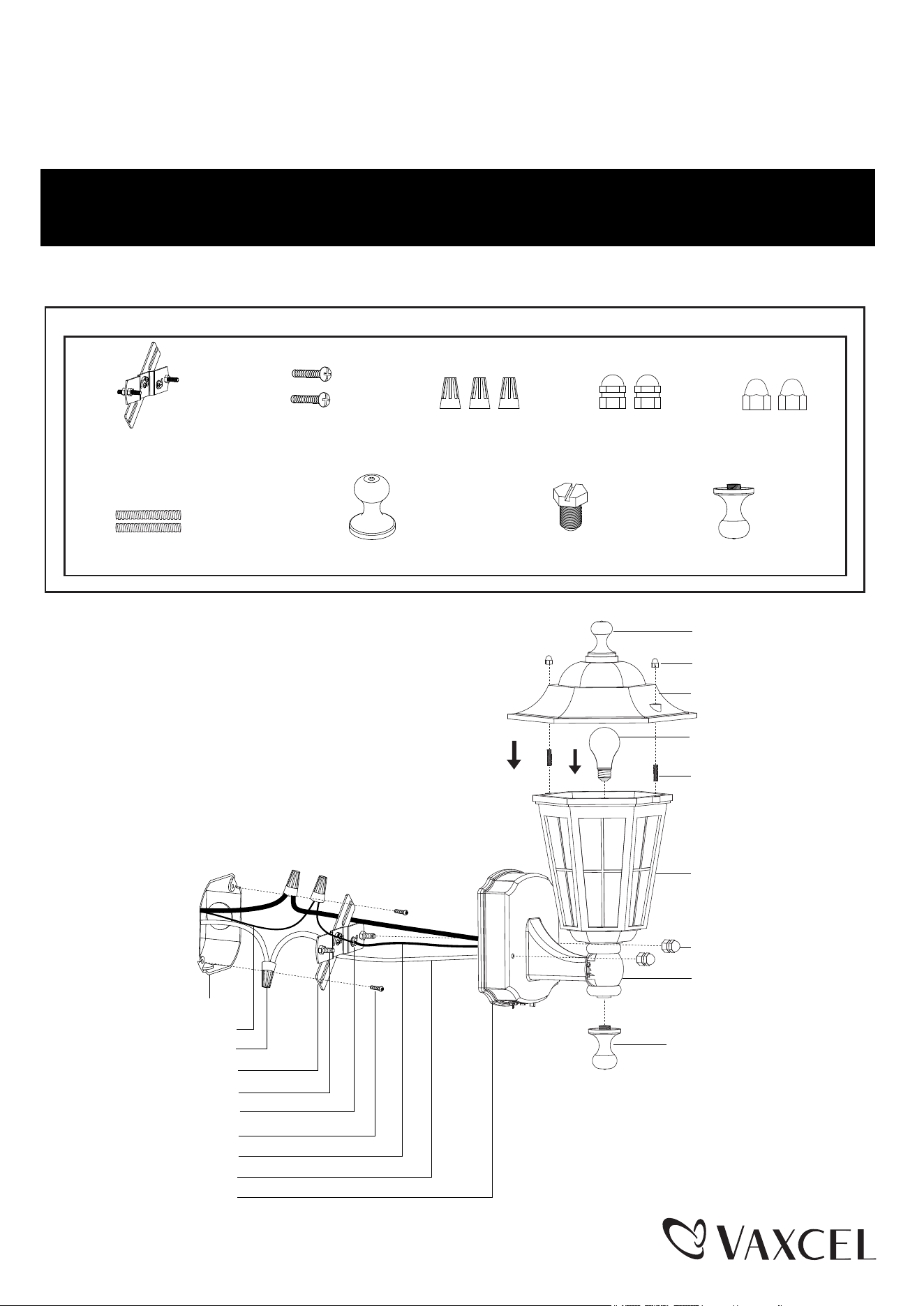
Hardware Package (included):
Mounting Screw (B) Wire Connector (C) Bolt Nut (D)
Top Finial (G)
Crossbar Unit (A)
Plastic Screw (H) Bottom Finial (I)
Decorative Cap Nut (E)
Headless Screw (F)
Wire Connector (C)
House Ground Wire
Outlet Box
Decorative Cap Nut (E)
Mounting Screw (B)
Green Ground Screw
Fixture Mounting Screw
Crossbar Unit (A)
Fixture Wire
Backplate
Fixture Ground Wire
Top Finial (G)
Headless Screw (F)
Metal Cover
Main Fixture
Bolt Nut (D)
Sensor Lens
Bottom Finial (I)
Max. 60W Type A Bulb
(not included)
Page 1 / 6
220822

Turn on the power at fuse or circuit box.
Turn off the power at fuse or circuit box
Installation Steps
1. Attach the crossbar unit (A) to the outlet box by using two mounting screws (B). Adjust the length of the preinstalled
fixture mounting screws if necessary.
Note: Make sure that the fixture mounting screws are lined up horizontally to make the fixture level.
2. Remove the plastic screw (H) from the top finial (G), then thread the plastic screw (H) through the hole of the metal
cover, and secure it with the top finial (G).
3. Install the bulb (not included). See relamping label at socket area or packaging for maximum wattage allowed.
4. Unscrew the two decorative cap nuts (E) from the two headless screws (F). Thread two headless screws (F) to the
main fixture. Attach the metal cover to the main fixture by inserting two headless screws (F), and secure it with two
decorative cap nuts (E).
5. Pull out the source wires from the outlet box. Make wire connections using wire connectors (C) as follows:
• Connect the hot wire (usually black insulation) from the fixture to the black wire from the power source.
• Connect the neutral wire (usually white insulation) from the fixture to the white wire from the power source.
• Connect the ground wire (usually green insulation) from the fixture to the house ground wire from the
power source.
Carefully put all of the wires back into the outlet box.
6. Attach the bottom finial (I) to the bottom of the sensor lens. Unscrew the two bolt nuts (D) from the crossbar unit (A).
Attach the backplate of the main fixture to the crossbar unit (A) by inserting fixture mounting screws into holes on
backplate, then secure it with two bolt nuts (D).
Note: With silicone caulk compound, caulk completely around where the backplate meets with the wall
surface to prevent water from seeping into the outlet box.
Important to know
1. This fixture requires a 120VAC, 60Hz power source.
2. Make sure the power is switched OFF before installation.
3. Motion sensor: turns light ON automatically when motion is detected and turns light OFF automatically when
motion stops.
4. Photocell keeps the light OFF during the daytime.
5. Do not attempt to take the lantern apart; there are no serviceable parts inside.
6. To avoid sensor damage by lightning or electrical surge make sure the ground wire is securely connected.
7. For general safety and to avoid any possible damage to the sensor, be sure the power is switched "off" before
replacing the bulb.
8. Only general ON/OFF wall switch applies for this fixture, the dimmable wall switch shouldn’t be required.
Maximum Wattage: 60W Bulb
Work Temperature: - 4°F~104°F
Page 2 / 6
220822
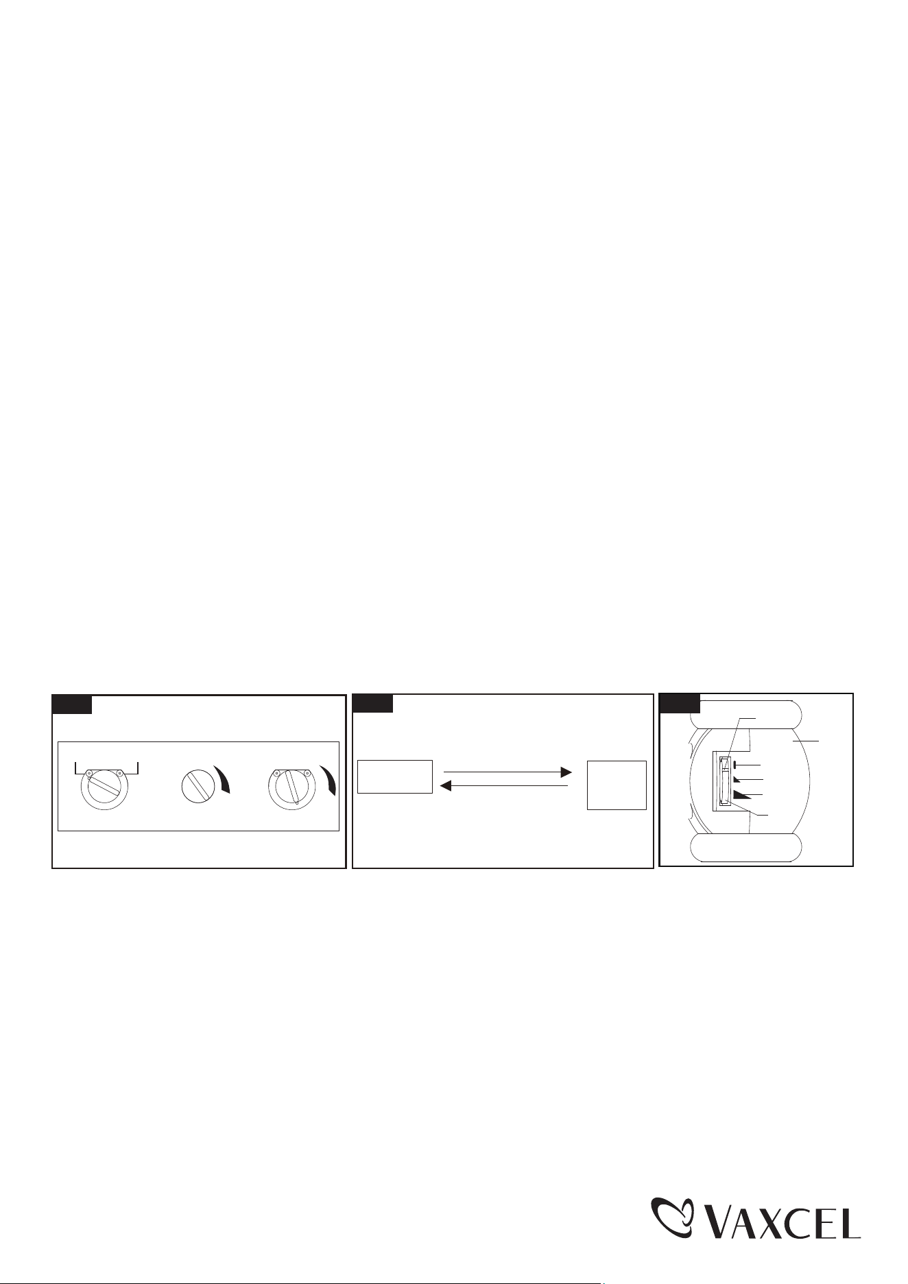
Customization Options
Shut-off Delay
The Shut-off delay is the length of time the light will stay on after motion has ceased to be detected.
This Shut-off delay can be set when operation is in “SECURITY” mode by using the “TEST/TIME” knob located on the
bottom of the back plate (See Fig.1) . To increase the shut-off delay, turn the knob clockwise. To decrease shut off delay,
turn the knob counterclockwise. The delay may be adjusted from a minimum of 5 seconds to a maximum of 10 minutes.
The light will stay on as long as motion is detected continuously and will automatically turn off when no more motion is
detected after the delay time has passed.
Choose a mode by rotating the knob on the bottom of the back plate. When power is first applied, the light will turn on
immediately. Wait for 15 seconds to allow the sensor to warm up.
1. TEST MODE(daytime or nighttime operation)
● Rotate knob on the bottom of back plate to the “TEST” position.
● When rotate the MODE SELECTOR knob to “SECURITY”, and rotate “TEST/TIME” knob arrow to point to
“TEST”, It is turned off after warming up. It is turned on when the motion is detected, and stayed on as long as
the motion continues. It is turned off about 5~30 seconds after the motion is no longer detected.
● When rotate the MODE SELECTOR knob to “DUSK TO DAWN”, and rotate “TEST/TIME” knob arrow to point to
“TEST”, it is turned on no matter whether the motion is detected or not.
2. DUSK TO DAWN MODE (nighttime operation only)
● To shift to “DUSK TO DAWN” mode, rotate the mode selector knob to “DUSK TO DAWN”, and rotate “TEST/TIME”
knob clockwise by 90° (the photocell is exposed). At dusk the light is turned on automatically, and the light is turned
off automatically at dawn.
3. SECURITY MODE (nighttime operation only)
● To shift to “SECURITY” mode, rotate the mode selector knob to “SECURITY”, and rotate “TEST/TIME” knob
clockwise to point to the desired time setting (between 5 seconds and 10 minutes). At dusk, when motion is
detected, the light is turned on and stayed on as long as motion continues. When the motion is no longer detected,
the light is remained on for the predetermined time you set (5s ~ 10min), and then turned off automatically.
● The light is turned off automatically at dawn.
4. Manual Override Mode (nighttime operation only) (See Fig.2)
● To temporarily override the settings in “SECURITY” mode for continuous on at night, rotate the mode selector knob
to “SECURITY”, and rotate “TEST/TIME” knob clockwise away from “TEST” position, turn the wall switch “OFF”
then turn it “ON” within 1~3 seconds, the light is remained on all night long. To shift back to “SECURITY” mode, turn
the wall switch “OFF”, 5 seconds later, turn it “ON”, the light is reset to initial state, wait for warming up then the light
is reverted back to “SECURITY” mode.
● The light is turned off automatically at dawn.
Manual
Override
Manual Override Operation Diagram
Turn wall switch OFF-ON
in 1~3 Seconds
Fig. 2
Fig. 1
(View from bottom of back plate)
SECURITY
Mode
DUSK/DAWN SECURITY
TIME
SENSITIVITY
TEST
Fig. 3
Coverage Dial
Moderate View Angle
Maximum View Angle
No View Angle
Lens
Slot
Turn off the wall switch,
and after 5 seconds
turn it on.
FUNCTION AND OPERATION
Page 3 / 6
220822
Sensitivity of Motion Sensor
The sensitivity of the motion sensor can be adjusted by using the “SENSITIVITY” knob located on the bottom of the back
plate (See Fig.1). To increase sensitivity, turn the knob clockwise. To decrease sensitivity, turn the knob counterclockwise.
The sensitivity may be adjusted from a minimum of 5 feet to a maximum of 30 feet.
Adjust The View Angle of Motion Sensor
Rotate the mode selector knob to “SECURITY”, and rotate “TEST/TIME” knob arrow to point to “TEST” (See Fig.1), walk
in the tested area, when the motion is detected, the light is came on, move to another tested spot, do the same action to
check the coverage area of motion detector. There are two coverage dials in the left and right of the lens.
When the slot in the coverage dial is aligned to “ ” (no view angle), the built-in detector is covered, the light does not
have motion sensor function.
When the slot in the coverage dial is aligned to “ ” (moderate view angle), the built-in detector is covered a portion, the
view angle is reduced.
When the slot in the coverage dial is aligned to “ ” (maximum view angle), the built-in detector is not covered, the
view angle is maximum.
Rotate either side of the left or right coverage dial or both side of coverage dials to choose desired view angle (See Fig.3).
5`
6`
8`
30`
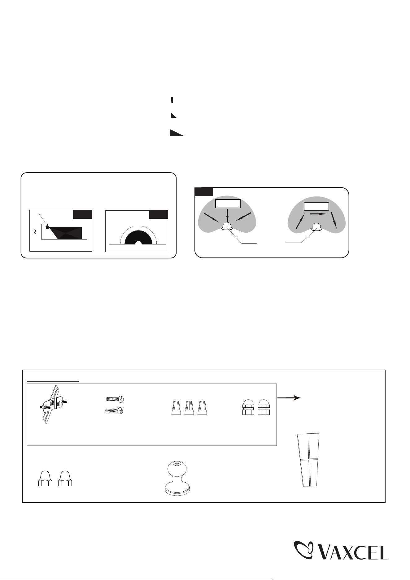
Where you install your lantern is important:
Be sure the light is mounted straight on the wall;
otherwise, the detection distance may be limited.
Fig. 4 Fig. 5
180˚
Motion
Least sensitive
Motion
Most sensitive
Sensor
Fig. 6
NOTE:
1. The sensitivity of the motion sensor will increase as the environmental temperature gets cooler. For best performance,
gently clean the lens with a soft cloth every 1 or 2 months to assure maximum sensitivity.
2. For best performance, install fixture at least 6 feet above the ground. At such a height, the fixture will provide a
detection distance of up to 30 feet at 77 degrees Fahrenheit. (See Fig.4)
3. The sensor detects across a detection range of 180 degrees. (See Fig.5)
4. The sensor will be more sensitive to motion across its detection path than motion directly towards it. (See Fig.6)
5. To reduce possible nuisances, do not mount the fixture near a heat source like an air conditioner, vent or furnace
exhaust, or in a direction facing any reflecting object or other light source.
The following parts are available for re-order if damaged or missing.
Spare Parts List:
Mounting Screw (B) Wire Connector (C) Bolt Nut (D)Crossbar Unit (A)
Top Finial (G)
4805FF For T0677
4808FF For T0678
Decorative Cap Nut (E)
4805CT For T0677
4806CT For T0678
Assembly Kit
4805MM (1 SET) For T0677
4808MM (1 SET) For T0678
Glass Panel
9472CS
Page 4 / 6
220822

TROUBLESHOOTING
PROBLEM POSSIBLE CAUSE
CORRECTIVE ACTION
If the light will not come on
There may be a poor connection between
the lamp fixture and supply wires inside the
outlet box.
Double check the wire connections.
The photocell may be detecting daylight and
preventing the light from coming on.
Turn the “TIME/TEST” knob to the
TEST position to turn off the photocell,
or wait until dusk and recheck.
Bulb may need replacement.
Remove bulb and check for a break in
the filament wire. Replace bulb if
necessary.
Coverage dial on either side of the motion
detector lens may be set so that the detector
is blocked.
Turn the dials downward to increase the
coverage area.
Motion detector lens may be installed upside
down. Gently pull lens out. The three drain
holes should be on the bottom.
Re-install lens to proper position.
The fixture will only operate on standard
120VAC/60Hz power.
Have power supply checked by
qualified electrician.
There may not be enough light being
detected by the photocell.
On cloudy or overcast days, the light
may stay on longer than intended. No
corrective action needed.
If the light flashes or blinks
The photocell maybe detecting light from
the lamp and could be responding as if
the light from the bulb were daylight.
Try lower wattage bulb.
If the light Stays on
The SENSITIVITY may be set too high.
Try reducing the SENSITIVITY in small
steps.
Motion detector lens may be installed upside
down.
Gently pull lens out. The three drain
holes should be on the bottom.
Re-install in proper position.
The coverage area may be too large and the
motion detector is sensing unwanted motion.
Try adjusting the coverage dials on
either side of the motion detector lens
upward to reduce the coverage area.
Light will not go on or off
Shut-off delay time is too short.
To increase the shut-off delay time,
rotate the knob clockwise.
In Manual override, the light
is not stayed on at dusk
Too much light is shining onto sensor due to
another light source, such as a street lamp
or other light fixture.
Eliminate or turn off other light source,
block other light source from shining
onto sensor, or relocate fixture.
Page 5 / 6
220822
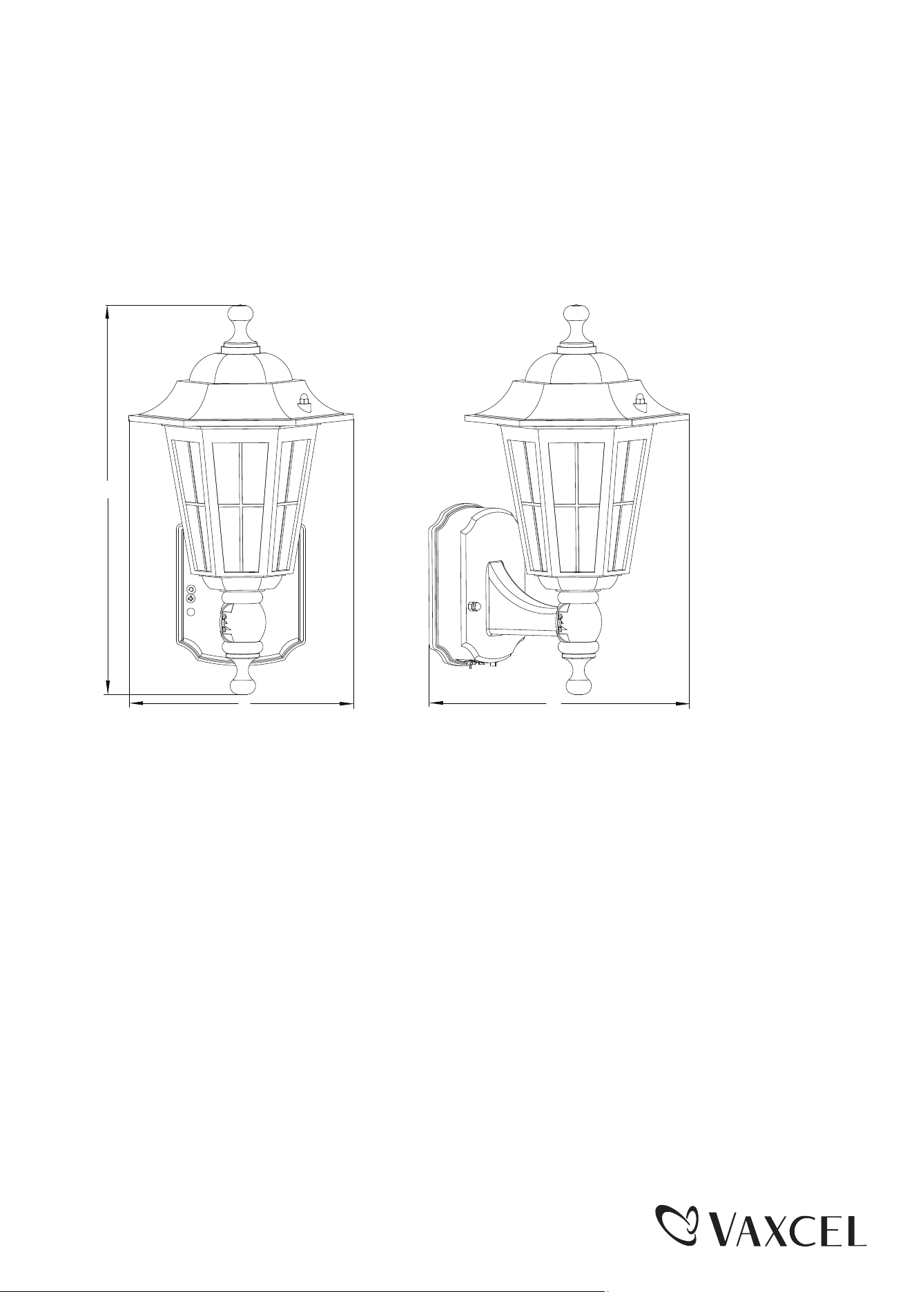
A: 14-1/4"
B: 8"
C: 8-1/4"
A
B C
Page 6 / 6
220822