BULLETIN NO.
PN0006853
SERVICE PARTS LIST
CATALOG NO. MXF600
REVISED BULLETIN DATE
SPECIFY CATALOG NO. AND SERIAL NO. WHEN ORDERING PARTS
MX FUEL™
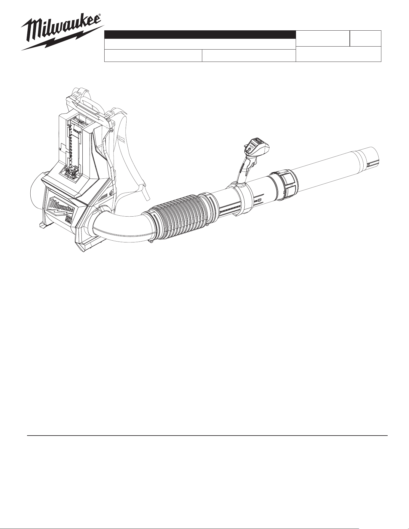
Backpack Blower
Aug. 2025
WIRING INSTRUCTION
P31A
SERIAL NO.
See Pages 4-5
Only maintenance, service, repairs, and replacements of parts as dened in the Operator's Manual
can be performed by the user.
All other repairs are to ONLY be performed by personnel authorized by MILWAUKEE TOOL. Do not
attempt to install other parts; this COULD void your tool warranty.
For service, parts, or inquiries, contact us:
• Customer Service at 1.800.SAWDUST (1.800.729.3878)
• E-Service tool repair at: www.milwaukeetool.com/e-service
• Find a local authorized MILWAUKEE service location at Milwaukeetool.com
• Find a MILWAUKEE factory Service Center Location or MILWAUKEE factory Central Repair
Center at Milwaukeetool.com. Send the following, posted paid and insured:
• Your name, address, and phone number
• Description of the issues
• Copy of the proof of purchase
• Tool, charger, and batteries involved with the issues
MILWAUKEE factory Central Repair Centers:
MILWAUKEE TOOL MILWAUKEE TOOL
Central Repair Central Repair
1401 Sycamore Avenue 2198 Southtech Drive
Greenwood, MS 38930 Greenwood, IN 46143
MILWAUKEE TOOL
l
www.milwaukeetool.com
13135 W. LISBON RD., BROOKFIELD, WI 53005
Drwg. 2
90
92
12
24
67
28
48
2
55
(2x)
64(2x)
68
(2x)
52
(2x)
66
63
56
51
88
34
54
(2x)
70
(8x)
65
(2x)
18
72
(4x)
60
(6x)
58
33
85
32
53
(2x)
5
17
39(4x)
22
69
(4x)
45
46
47
25
27
37(7x)
26
72
(8x)
82
50
38(4x)
29(8x)
62
72(12x)
72
(3x)
71
(2x)
84
86
41(2x)
1
36(2x)
39
10
39(8x)
28
69
108
38
45
113
22
67
101
10
39
104
72
84
112
71
86
114
5 12 17 21
24 39 90 92
100
26 27 29 37
46 47 72
105
5 17
39
102
36 39
41 62
103
25 38
50 82
107
2 18 32 33 34 51
52 53 54 55 56 58
60 63 64 65 66 68
70 88
115
t
o
t
ub
e
EXAMPLE:
Component Parts (Small #)
Are Included When Ordering
The Assembly (Large #).
0
00
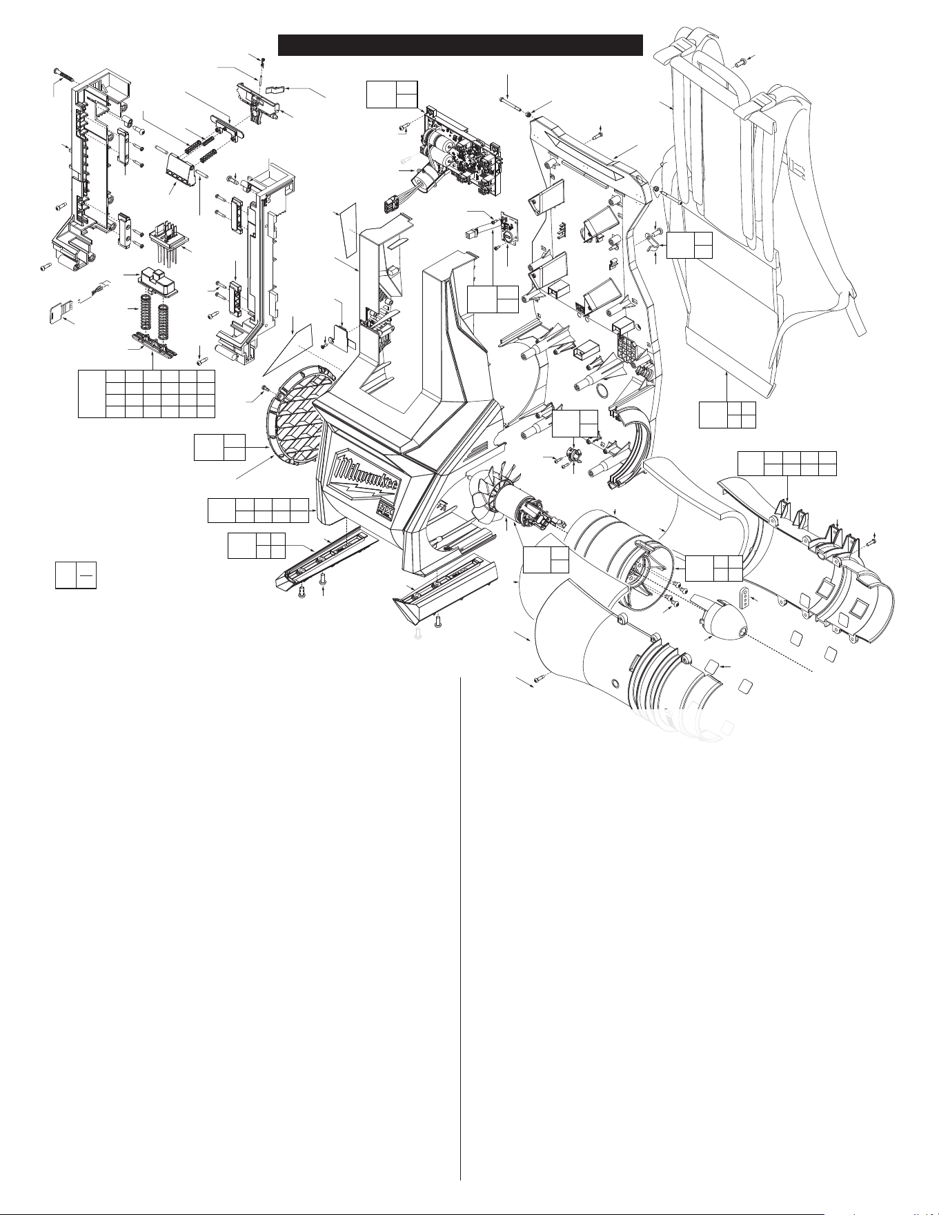
MXF BACKPACK BLOWER EXPLODED VIEW
FIG. PART NO. DESCRIPTION OF PART NO. REQ.
1 44-66-1102 Back Plate (1)
2 42-42-0029 Battery Ejector (1)
5 --------------- Foot (Left) (1)
10 --------------- Nozzle Hook Clip (1)
12 --------------- Access Door (1)
17 --------------- Foot (Right) (1)
18 44-34-0021 Ejection Spring Holder (1)
19 43-33-0022 Elbow (1)
21 --------------- Front Cover (1)
22 --------------- Grommet Cover (1)
24 --------------- Coin Cell Door Screw (1)
25 --------------- Inlet Duct (1)
26 --------------- Inlet Muer Cover (1)
27 --------------- Inlet Muer Support (1)
28 42-52-0047 Inlet Vent (1)
29 44-52-1001 Isolating Rubber Pad (8)
32 --------------- Latch (1)
33 --------------- Power Pack Rail (Left) (1)
34 44-10-0021 Lever Lock Out (1)
36 05-81-0277 M4 x .7 Pan Hd. T-20 Screw (2)
37 05-81-1221 M4 x .7 Pan Hd. T-20 Screw (7)
38 05-78-0029 M5 x 8mm Machine Screw (4)
39 05-81-0132 M6 x 1 Pan Hd. T-30 Screw (13)
41 05-55-0101 Hex Nut w/Nylon Insert (2)
43 05-74-0200 M4 x 36.5mm Screw (1)
45 23-30-0002 Motor (1)
46 --------------- Muer Foam A (1)
47 --------------- Muer Foam B (1)
48 66-82-0002 Coin Cell Board (1)
50 31-15-0003 Outlet Cone (1)
51 44-60-5280 Lock O Lever Pin (1)
52 42-40-7080 Pivot Bushing (2)
53 06-65-7330 Pivot Shaft (2)
54 --------------- Rail Insert (2)
55 --------------- Rear Rail Insert (2)
56 44-10-0019 Release Lever (1)
57 --------------- Retaining Ring & Foam Sub-Assembly (1)
58 --------------- Power Pack Rail (Right) (1)
60 05-88-0002 M3 x 1.058 Pan Hd. T-10 Screw (6)
62 23-94-0013 Harness Assembly (1)
63 44-34-0022 Pivot Latch Spring Holder (1)
64 40-50-0106 Spring (2)
65 40-50-0109 Spring (2)
66 40-50-8945 Spring (1)
68 06-82-0029 M5 x 16mm Pan Hd. T-25 Screw (2)
70 06-82-9630 M3 Non-Return Tamperproof Screw (8)
71 06-82-0027 M3 x 7mm Pan Hd. T-10 Screw (2)
72 06-82-1076 M4 x 1.41 Pan Hd. T-20 Screw (27)
74 22-22-0023 Throttle Control Tube (1)
76 34-40-0234 Telescoping Tube Pivot Ring (1)
77 42-90-0038 Telescoping Tube Threaded Coupler (1)
78 42-90-0034 Telescoping Tube Threaded Handle Adapter (1)
82 22-90-0001 Wire Grommet (1)
83 05-81-2005 M5 x .188 Pan Hd. T-25 Screw (2)
84 --------------- Main Control Board (1)
85 --------------- Battery Terminal (1)
86 --------------- BLE Board (1)
88 40-50-0124 Lock-O Lever Torsion Spring (1)
90 10-22-2999 Caution Label (1)
92 12-20-2686 Service Nameplate (1)
100 14-46-1127 Front Cover Kit (1)
101 14-46-1130 Grommet Cover Kit (1)
102 14-46-1128 Feet Kit (1)
103 14-46-1129 Harness Kit (1)
104 14-46-1131 Nozzle Hook Kit (1)
105 14-46-1130 Muer Kit (1)
107 14-46-1133 Inlet Duct Kit (1)
108 14-46-1135 Muer Grate Kit (1)
112 14-20-0701 Power Control Board Kit (1)
113 14-50-0006 Motor Kit (1)
114 14-20-0702 BLE Board Assembly (1)
115 14-46-1154 Battery Rail Assembly (1)
FIG. PART NO. DESCRIPTION OF PART NO. REQ.
78
77
13
8
16
57
14
61
(2x)
19
20
72(2x)
9
83(2x)
3 4 6 7 15 23
30 31 35 43 49 59
67 69 72 73 75 79
80 81
116
76
35
4
23
75
72
3
73
(6x)
59
7981
6
49
80
15
31
89
67(2x)
69(2x)
72
(7x)
7
72
30
43
74
7 35
43
111
4 23 30 31
67 69 72
110
14
57
109
20
72
106
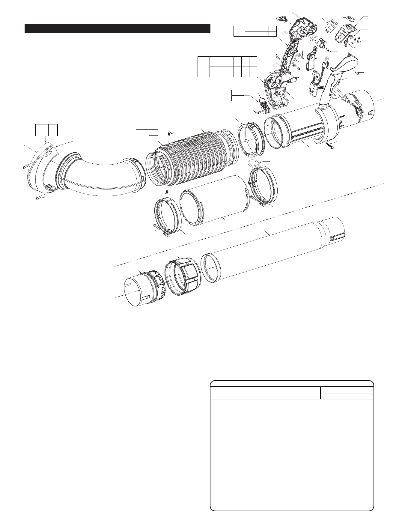
FIG. PART NO. DESCRIPTION OF PART NO. REQ.
3 42-42-0005 Speed Select Button (1)
4 42-36-0006 Power Cable Bracket (1)
6 31-11-0001 Cam (1)
7 31-42-0017 Handle Cam Lock (1)
8 28-10-0104 Clamp (Large) (1)
9 28-10-0103 Clamp (Small) (1)
13 22-22-0024 Combined Extension Tube (1)
14 31-01-1101 Corrugated Tube (1)
15 23-66-0002 Cruise Control Lever (1)
16 34-40-0233 D-Ring (1)
20 --------------- Elbow Cover (1)
23 22-38-0101 Grounding Wire (1)
30 --------------- Joystick (Left) (1)
31 --------------- Joystick (Right) (1)
35 31-10-0024 Lever Lock Pin (1)
49 34-40-1003 O-Ring (1)
59 31-15-0043 Rubber Arm Button (1)
61 44-86-0004 Plastic Retainer (2)
67 06-82-1080 M3 Screw (4)
69 05-88-1220 M4 x 10mm Pan Hd. T-20 Screw (6)
71 06-82-0027 M3 x 16mm Pan Hd. T-10 Screw (2)
72 06-82-1076 M4 x 1.41 Pan Hd. T-20 Screw (11)
73 06-82-0153 Ball Bearing (1)
75 23-66-0003 PCBA Assembly (1)
79 23-35-0001 UI Panel (1)
80 10-05-1011 UI Label (1)
81 10-05-1012 UI Label (1)
89 22-80-0003 UI PCB Board (1)
106 14-46-1132 Elbow Cover Kit (1)
109 14-46-1136 Corrugate Kit (1)
110 14-46-1139 Joystick Shell Kit (1)
111 14-46-1138 UI Latch Kit (1)
116 14-46-1156 Joystick Assembly (1)
FIG. NOTES
80,81 A clean, dry surface is essential for proper performance for any
adhesive system. The area intended for application of any ad-
hesive label or nameplate must be prepared by cleaning with
isopropyl alcohol. The solvent is to be applied with a clean, lint
free applicator and the surface allowed to dry before applying
any label or nameplate.
FIG. PART NO. DESCRIPTION OF PART NO. REQ.
MXF BACKPACK BLOWER EXPLODED VIEW (continued)
SCREW TORQUE SPECIFICATIONS
SEAT TORQUE
FIG. PART NO. WHERE USED (kgf-cm) (lb-in)
24 --------------- Coin Cell Door 3±1 3±1
36 05-81-2550 Back Plate Straps 5±0.5 4±0.4
37 05-81-1221 Muer Halves 10±1 9±1
38 05-78-0029 Motor to Stator 20±2 17±2
39 05-81-0132 Harness/Feet 30±3 26±3
43 05-74-0200 Cam Lock 3.5±0.5 3±0.4
60 05-88-0002 Battery Rail Assy. 23±2 20±2
61 05-88-0001 Cam to Cruise Lever 8±1 7±1
67 06-82-1080 Grommet Cover 4±0.5 3±0.4
68 06-82-0029 Batt. Rail Pivot Bushings 23±2 20±2
69 05-88-1220 Grnd Wire/Muer Grate 8±1 7±1
70 06-82-9630 Battery Rail Inserts 5±0.5 4±0.4
71 06-82-0027 BLE Board 4±0.5 3±0.4
72 06-82-1076 Handle Halves 10.3±1 8.9±1
Back Plate 12.5±1 10.8±1
73 06-82-0153 UI 4±0.5 3±0.4
83 05-81-2005 Corrugate Tube Clamps 35±2.5 30±2.2
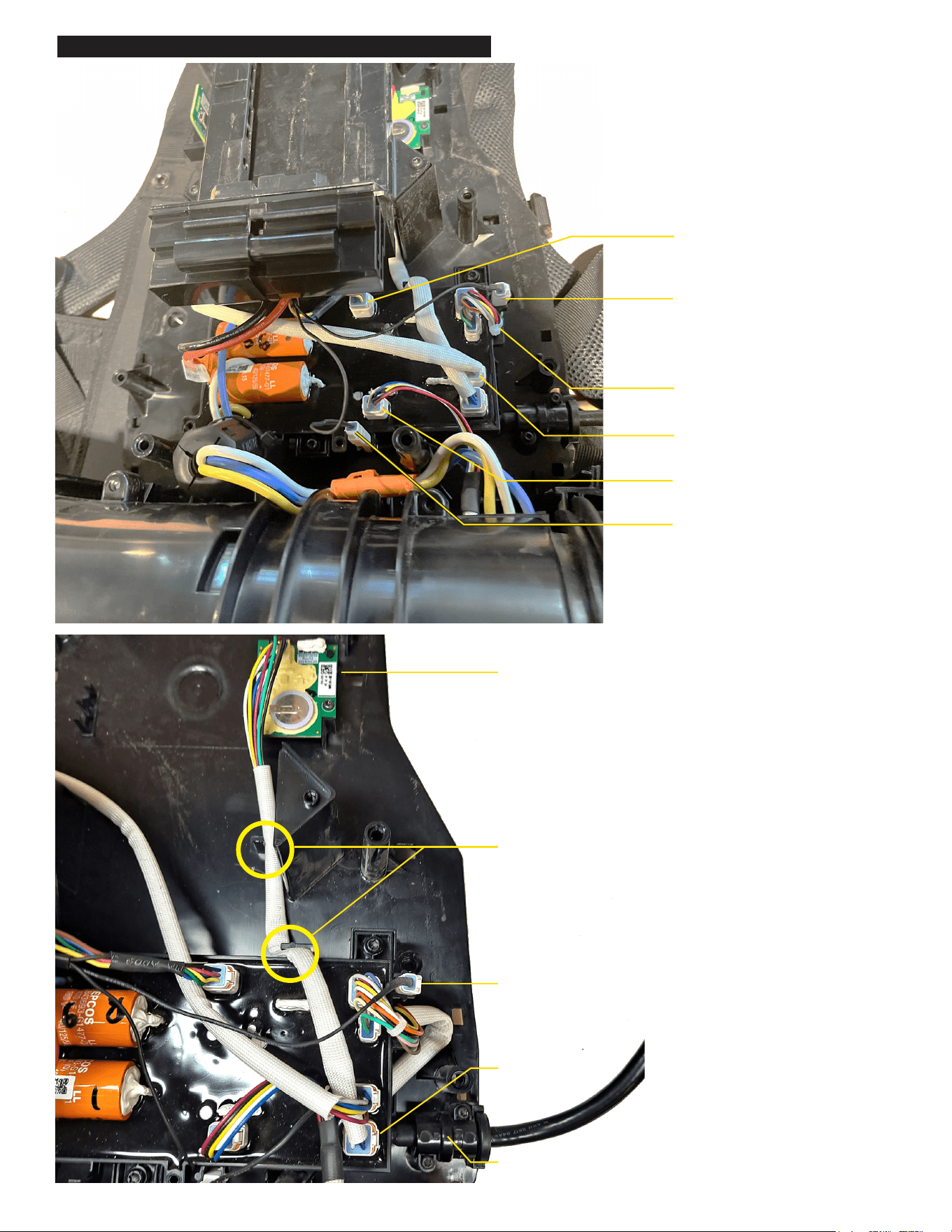
Mount UI Harness Grommet
in Backplate as shown
Place BLE board in
backplate as shown
Route BLE board
through wire traps
Place UI Connector
into clip
Plug in BLE board
wire connector
Plug Coin Cell Board
Connector into PCBA
Plug Connector
Assembly from Battery
Rails into PCBA
Plug one of Male Ground
Connectors from Battery Rails
into UI Connector attached to
PCBA. Be sure connector stays
seated in clip.
Slide UI wires into wire
trap as shown
Plug Hall Sensor Wires
Connector into PCBA
Connect Female Ground Connector
from Inlet Assembly to remaining Male
Ground Connector from Battery Rails
and Place in Connector Clip as shown
MXF BACKPACK BLOWER WIRING - BACKPLATE
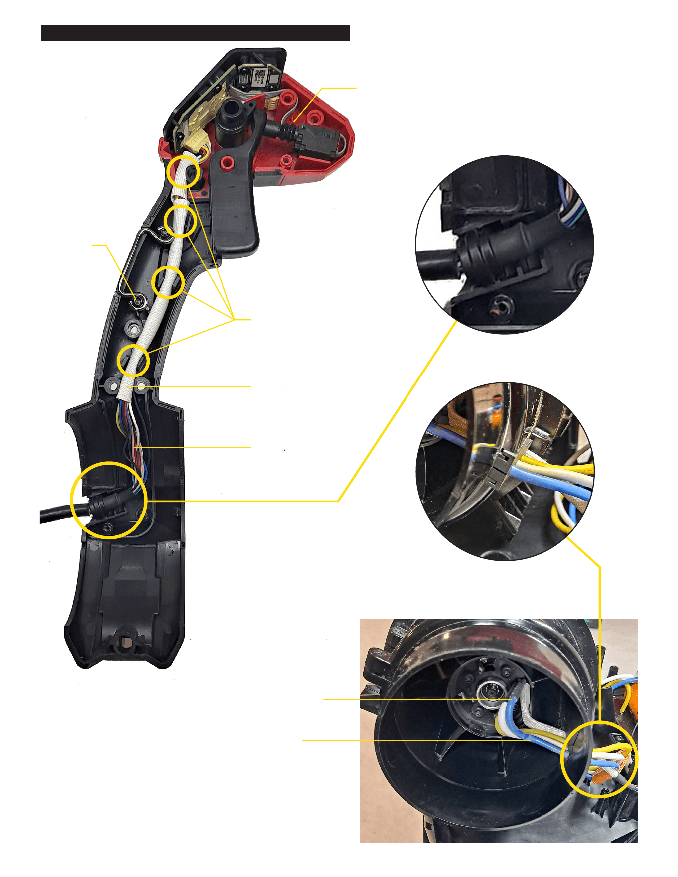
Grommet to be seated
in location shown
Wires to be seated
between bottom two
screw bosses
Wires to be routed
through wire traps
as shown
Fasten ring terminal to
lower ground wire screw
boss. Be sure to
sandwich ring terminal
between ground wire
and fastener
Place switch wire above handle
mounts with excess wire loop
between screw bosses
Wires to be routed
within channel
Slide motor wires
through large slot
in stator
Excess wire
looped inside
of exit cone
Make sure there is 4cm of wire
exposed past grommet
Grommet to be fully seated in stator ribs
MXF BACKPACK BLOWER WIRING - UI & STATOR