18
17
16
(2x)
19
14
21
6
5(4x)
46c
26
28
2
43
7
3
13
(2x)
46d
13
(2x)
46b
23
22
23
24
30
46a
13
(10x)
15
1
34
(2x)
25
40
15 30
32 33
42
3
6
44
21 23
24
46
46a 46b
46c 46d
47
2
14
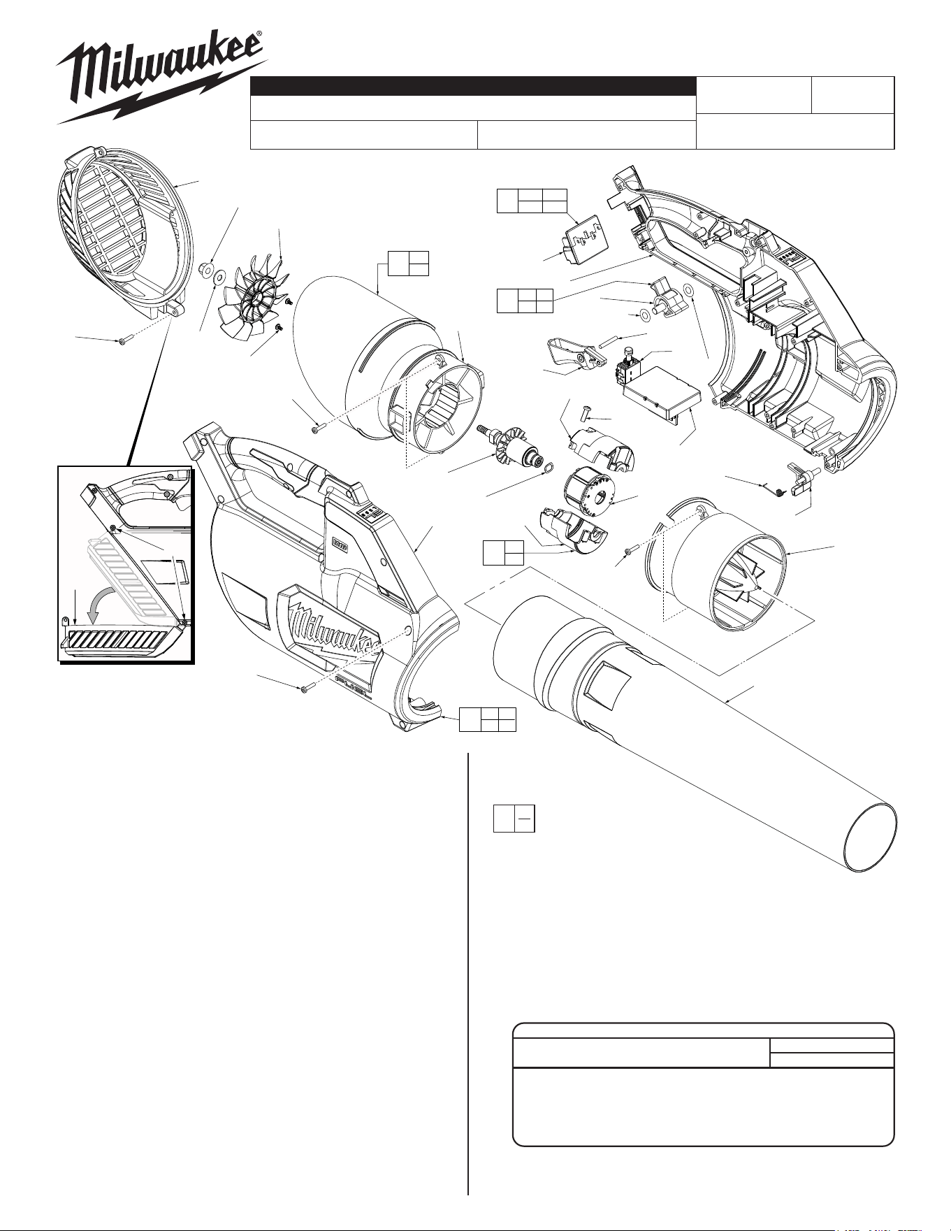
Remove top screw and
loosen bottom screw (34)
to gain access to Fan (17)
through the Intake Vent
Cover (19).
34
19
FIG. PART NO. DESCRIPTION OF PART NO. REQ.
46 14-20-2728 Electronics Assembly 1
46a --------------- Battery Terminal Block Assembly 1
46b --------------- Switch 1
46c --------------- PCBA/Hall Board 1
46d --------------- Stator Assembly 1
47 22-84-0101 Static Fan Service Kit 1
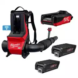
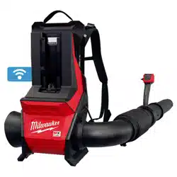
M18 FUEL™ BLOWER
2728-20
H33A
54-05-2700
See Page 2
Aug. 2022
REVISED BULLETIN
SERVICE PARTS LIST
BULLETIN NO.
WIRING INSTRUCTION
DATE
SPECIFY CATALOG NO. AND SERIAL NO. WHEN ORDERING PARTS
CATALOG NO.
STARTING
SERIAL NO.
EXAMPLE:
Component Parts (Small #)
Are Included When Ordering
The Assembly (Large #).
0
00
FIG. PART NO. DESCRIPTION OF PART NO. REQ.
1 43-24-0400 Exhaust Tube 1
2 --------------- Cone Section 1
3 --------------- Motor Insulator-Right 1
5 06-82-6350 M3 x 16 Pan Hd. ST T-10 Screw 4
6 --------------- Motor Insulator-Left 1
7 45-88-0167 Wave Washer 1
13 05-88-1200 M4 x 18 Pan Hd. ST T-20 Screw 14
14 --------------- Static Fan 1
15 --------------- Housing Cover - Right Housing Halve 1
16 06-82-3835 #6-19 PT T-15 Screw 2
17 22-84-0006 Fan 1
18 05-55-0033 M7 x 1 Hex Nut 1
19 31-15-0044 Intake Vent Cover 1
21 --------------- Trigger 1
22 06-65-0061 Steel Pin 1
23 34-40-0054 O-Ring 2
24 --------------- Speed Dial 1
25 45-88-0161 Washer 1
26 40-50-0064 Spring 1
28 44-20-0076 Nozzle Lock 1
30 --------------- Housing Support - Left Housing Halve 1
32 10-20-1042 Caution Label (Not Shown) 1
33 12-20-0087 Service Nameplate (Not Shown) 1
34 05-88-1650 M4 x 25mmPan Hd. ST T-20 Screw 2
40 31-44-2728 Housing Kit 1
42 23-16-0110 Motor Insulator Kit 1
43 16-01-0065 Rotor Assembly 1
44 43-98-0285 Trigger / Speed Dial Kit 1
MILWAUKEE TOOL
l
www.milwaukeetool.com
13135 W. Lisbon Road, Brookeld, WI 53005
Drwg. 6
SCREW TORQUE SPECIFICATIONS
SEAT TORQUE
FIG. PART NO. WHERE USED (KG/CM) (IN/LBS)
13 05-88-1200 Housing, Static Fan 8-12 6.9-10.4
5 06-82-6350 Motor Insulator 4-8 3.4-6.9
16 06-82-3835 Static Fan 3-6 2.6-5.2
18 05-55-0033 Fan 17-20 14.7-17.3
34 05-88-1650 Intake Vent Cover 8-12 6.9-10.4
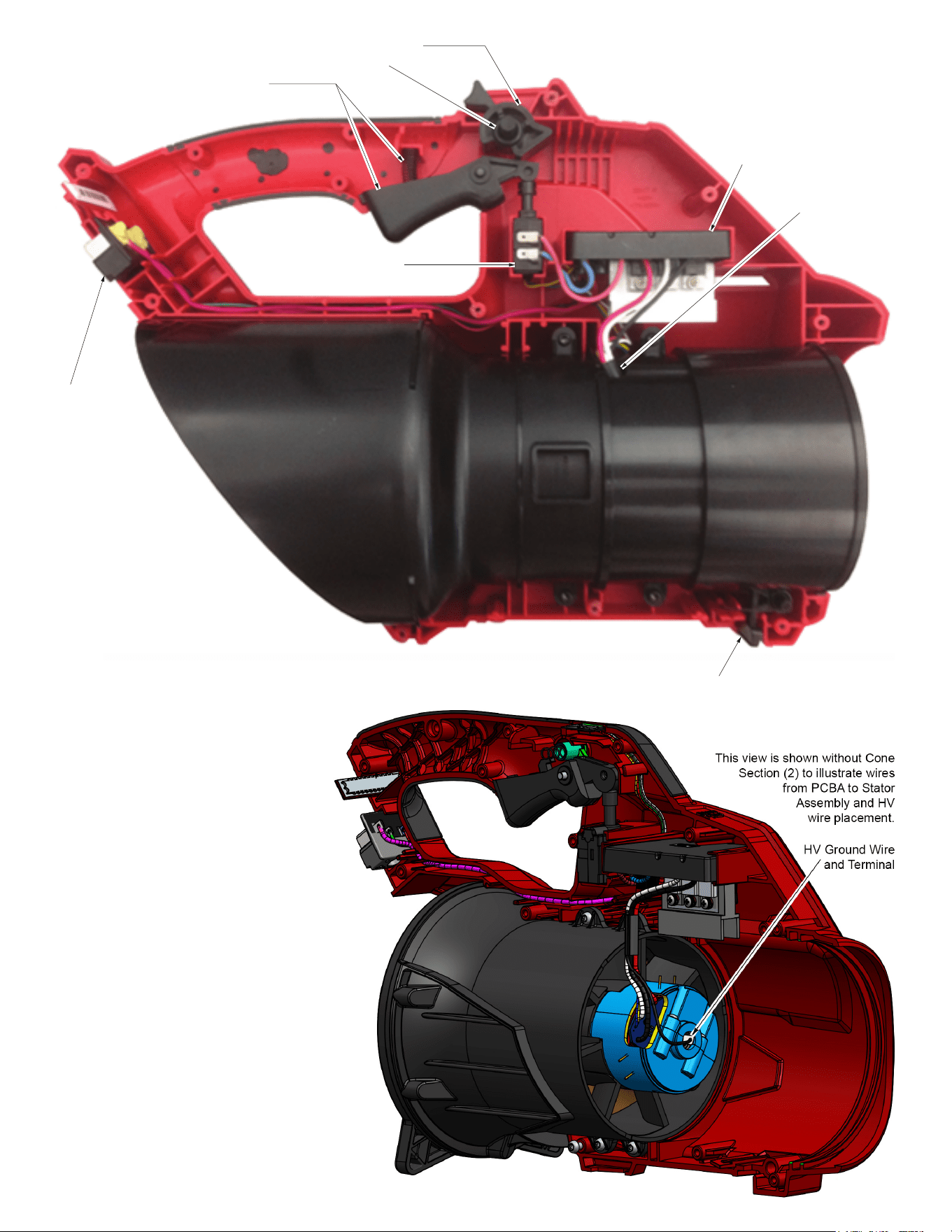
46a
Battery Terminal
Connector Block
46c
PCBA
46b
On-Off Switch
46d
Stator Assembly/
Hall Board
Nozzle Lock and
Nozzle Spring (26 and 28)
24 Speed Dial with
O-Rings (23) on each side
21 Trigger with
Compression Spring (20)
WIRING INSTRUCTIONS
• Place PCBA (46c) and the
On-O Switch (46b) squarely
and rmly in place in the Housing
Support (30) cavities.
• Route wires from the Switch and PCBA
as shown, tucking the wires down into the
wire traps.
• Route PCBA wires along the Housing Support
channel (removing any slack) and place Battery
Terminal Connector Block (46a) squarely and
rmly into position. Be sure the wires are pushed
down into the wire traps.
• Note routing and placement of the HV ground
wire. HV terminal to be placed as shown at
rear of Motor Insulator halves.
• Be sure the Trigger (21), Spring (20), Speed
Dial with O-Rings (24 and 23) are properly in
place.
• Be sure the Nozzle Lock and Nozzle Lock
Spring (26 and 28) are in place.
• Place Intake Vent Cover (19) onto Support
• Housing and carefully place Housing Cover (15)
onto the Housing Support (30).
• Secure the Intake Vent Cover (19) between the
housing halves using the two longer screws (34).
• Secure the housing halves together using 10 of
the shorter screws (13).
• Check for the proper functionality of the Switch
Trigger (21) and Speed Dial (24).
• Insert battery pack and check tool for proper
operation.