
Technical Support and E-Warranty Certificate www.vevor.com/support
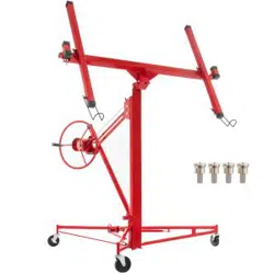
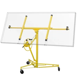
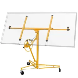
DRYWALL AND PANEL HOIST
MODEL:LG-021/LG-022
We continue to be committed to provide you tools with competitive price.
"Save Half", "Half Price" or any other similar expressions used by us only
represents an estimate of savings you might benefit from buying certain tools
with us compared to the major top brands and does not necessarily mean to cover
all categories of tools offered by us. You are kindly reminded to verify carefully
when you are placing an order with us if you are actually Saving
Half in comparison with the top major brands.
- 1 -
MODEL:LG-021/LG-022
NEED HELP? CONTACT US!
Have product questions? Need technical support? Please feel free to
contact us:
Technical Support and E-Warranty Certificate
www.vevor.com/support
This is the original instruction, please read all manual instructions
carefully before operating. VEVOR reserves a clear interpretation of our
user manual. The appearance of the product shall be subject to the
product you received. Please forgive us that we won't inform you again if
there are any technology or software updates on our product.
DRYWALL AND PANEL
HOIST
- 2 -
PARAMETER LIST
Model
LG-021
LG-022
Max. Load(lbs)
150
150
Max. lifting height:
3350
4860
Min. lifting height:
1420
1910
Net Weight:
36
40
Product Size(mm)
1360*1320*1420
1320*1360*1910
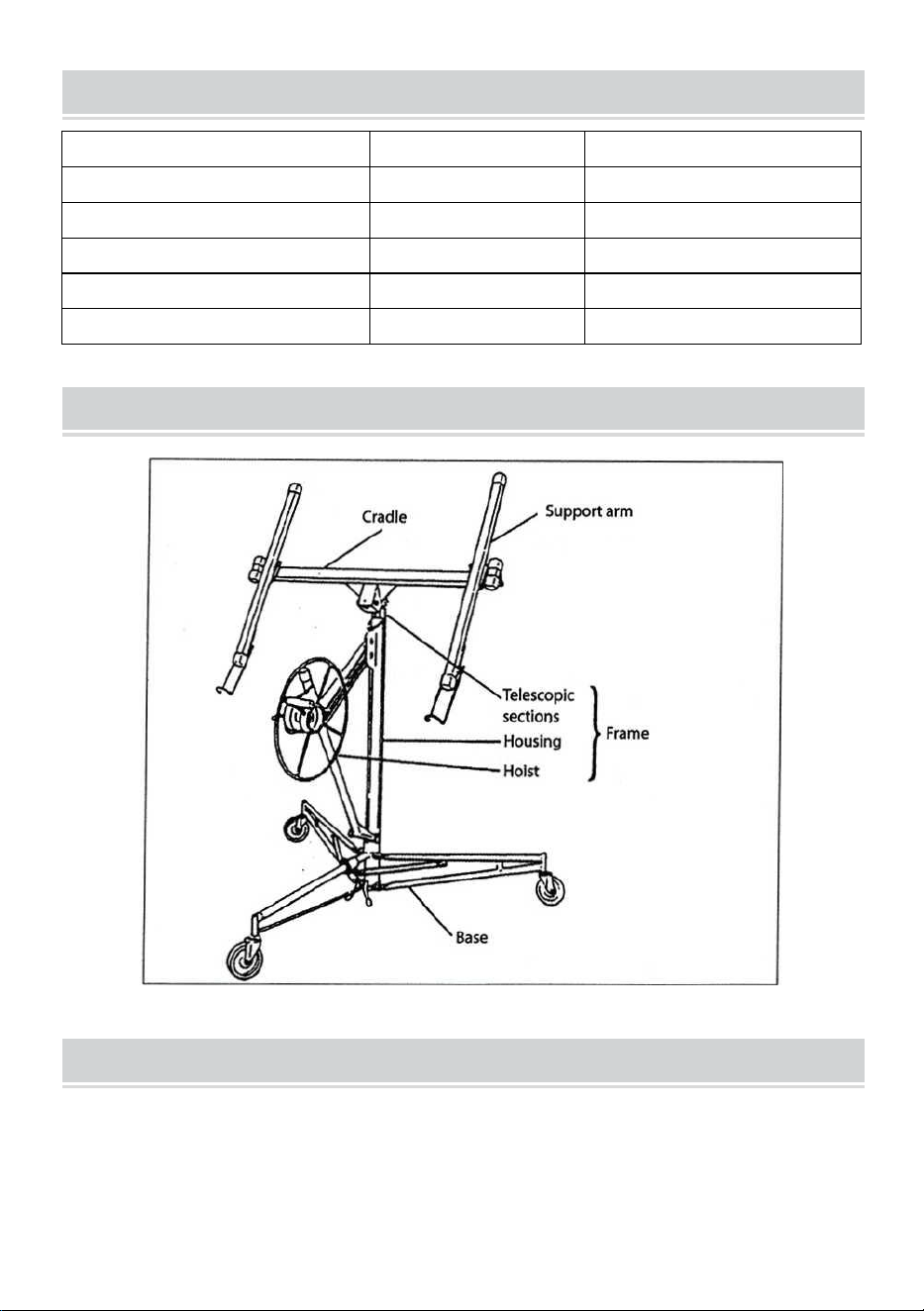
PART LIST
SECURITY & WARNINGS
To get the most out of your new plasterboard lift, please read through these
instructions and the attached safety instructions before use.
Please also save the instructions in case you need to refer to them at a

- 3 -
later date.
One person can lift a covering board with a size of up to 122x488 cm by
using the plasterboard lift without any additional help. The covering board
can be lifted a maximum of 335 cm from the floor to flat ceilings, sloping
walls or other walls when the tilt function is used.
The cradle of the plasterboard lift can be lowered to 138cm from the floor
so that it is easy to load a board onto it. The plasterboard lift can tolerate
loads up to 68 kg.
These instructions describe how the plasterboard lift is assembled, used
and dismantled for transport and storage. Please read these instructions
carefully before using the plasterboard lift for the first time.
• ALWAYS read the instructions before use and observe all warnings.
• ALWAYS inspect the plasterboard lift the day before use and pay attention
to the condition of the wire.
• ALWAYS allow the plasterboard lift to reach room temperature before use.
If you move the plasterboard lift from a cold room to a warm one;
condensation may form, which may affect the function of the brake!
• Check the brake drum is clean and dry before use.
• NEVER use the plasterboard lift unless both arms are secured with the
lock tab.
• ALWAYS keep the work area free of obstructions.
• ALWAYS wear a helmet when using the plasterboard lift.
ALWAYS be aware of obstructions above the plasterboard lift when lifting
boards.
• NEVER use the plasterboard lift for lifting objects other than
plasterboards and similar.
NEVER lift more than one board at a time. Never lift more than 68 kg.
OPERATION
Parts
The plasterboard lift is supplied in parts that must be assembled
before use:

- 4 -
-Base
• Frame including hoist and11ft(123cm)/16ft(175cm) telescopic sections
• Cradle without removable support arms
• Two support arms
Assembly instructions
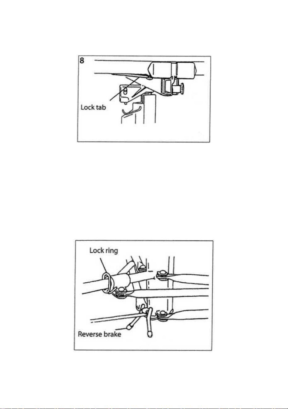
1.Set the base up:
Place the base on the floor so that it rests on its wheels.
Press the lock ring down. Hold the lock ring down while you swing the two
front legs out so that the lock ring engages with the hole at the bottom of
the tube. (See figure 1).
To prevent the base from rolling backwards while assembling it, flip the
reverse brake down as shown.
Position the frame on the two V angles on the base and lower the frame
around 2.5 cm until it sits firmly in the angles.
2.Before continuing, make sure that the frame is pushed fully down and
that it is secure in the angles.
3.Attach the handle to the handwheel for the hoist. Tighten the nut and
then loosen it slightly so that the handwheel rotates freely.
4.Move the hoist to the working position: Hold the handwheel and brake
lever as shown in Figure 2.
Turn the handwheel slightly forward while lifting the brake lever to release
the brake.
Lift the brake lever up fully. Take hold of the strut by the hoist and hold the
brake lever with your thumb. (See Figure 3).
Once the hoist has been drawn completely out (away from the frame),
release the brake lever and flip the lock hook away so that it no longer
- 5 -
holds the telescopic sections inside the frame.
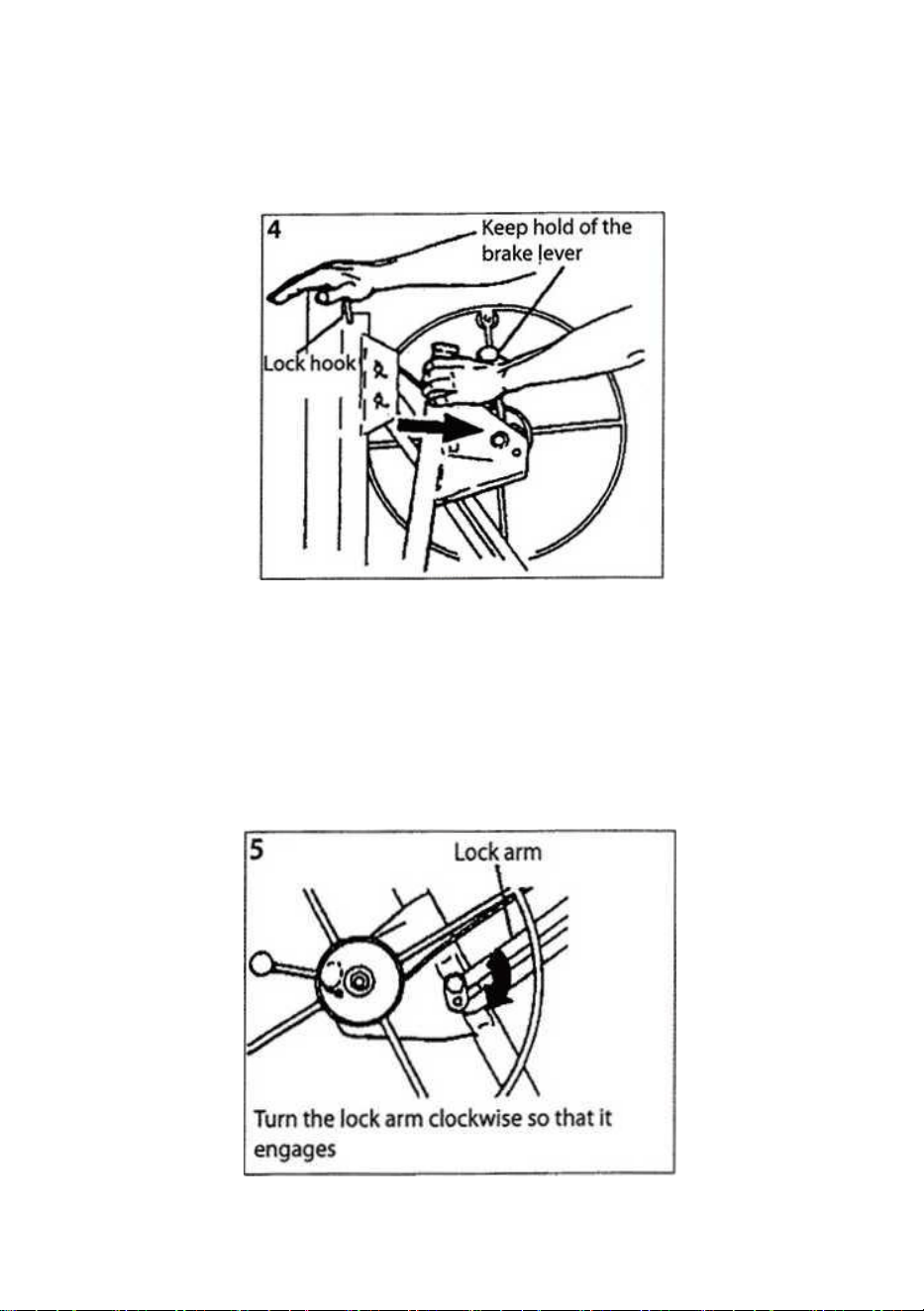
Place your right hand at the top of the frame. Continue to hold the brake
lever to avoid the wire retracting and pull the hoist towards you. (See
Figure 4).
5.Press the hoist gently back towards the frame. This allows the lock arm
to engage with the hoist and keep it fully out. (See Figure 5).
IMPORTANT! Before proceeding, make sure that the lock arm has
engaged correctly, i.e. has turned as far clockwise as possible.
WARNING! In order to avoid an accident, the lock arm must be fully
engaged when the hoist is pulled out.
- 6 -
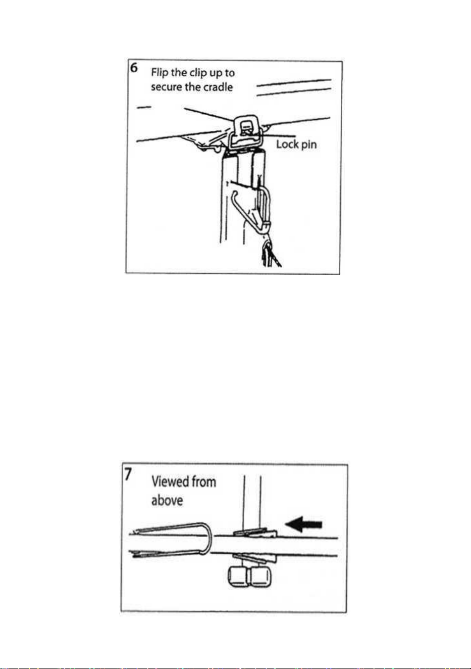
6. Attach the cradle to the frame (figure 6):
a.Insert the cradle strut into the opening at the top of the frame.
b.Secure the cradle to the frame by pressing the clip up over the lock pin
so that it clamps the cradle tight.
7. Attach the support arms to the cradle: NOTE! The support arms are
identical.
a.Push the tapered plates on the support arms into the tapered sockets on
the cradle. (See figure 7).
- 7 -
b. Push both support arms into the sockets until the lock tab at the bottom
of each support arm engages. (See figure 8).
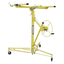
Operating parts
Lock ring
Press the lock ring down to release the two front legs so that they can be
rotated out to the working position or into the storage position. A
spring-loaded tab engages with a hole at the bottom of the tube to lock the
legs in position.
- 8 -
Reverse brake
Flip the reverse brake down to prevent the base from rolling backward, or
flip it up to allow it to move freely.
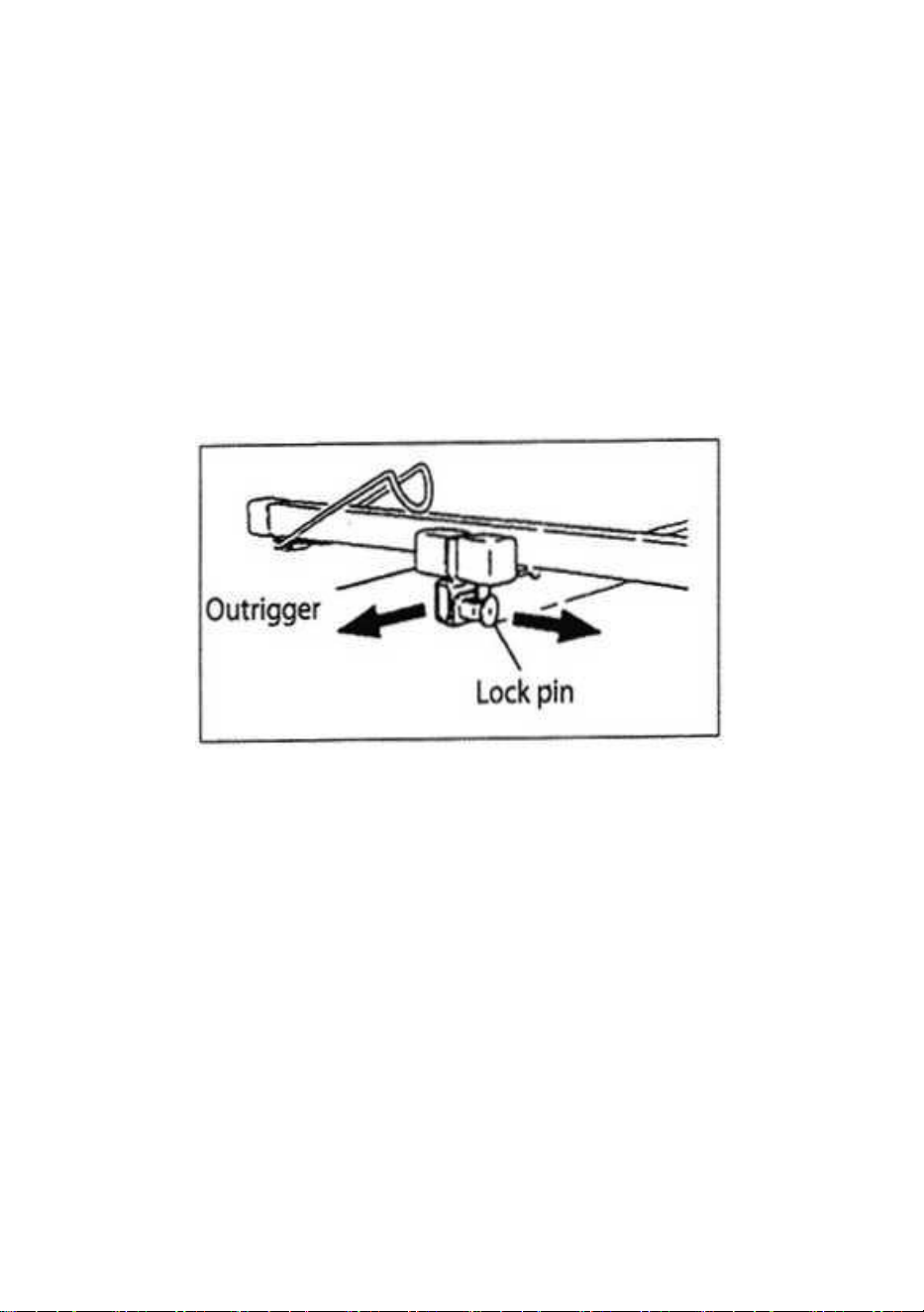
Outriggers
The outriggers on the support arms can be pulled out so that the
plasterboard lift can support a larger covering board.
Pull the lock pin with your right hand and pull the outrigger out using your
left hand. The lock pin can secure the outrigger in one of three positions:
Folded in or extended by 53 or 84 cm.
IMPORTANT! Never load a covering board on the cradle and never use
the lift if the lock pins have not engaged in one of these three positions or if
the outriggers have been pulled out more than 84 cm.
To avoid damaging the outriggers, push them fully in before transporting or
storing the plasterboard lift.
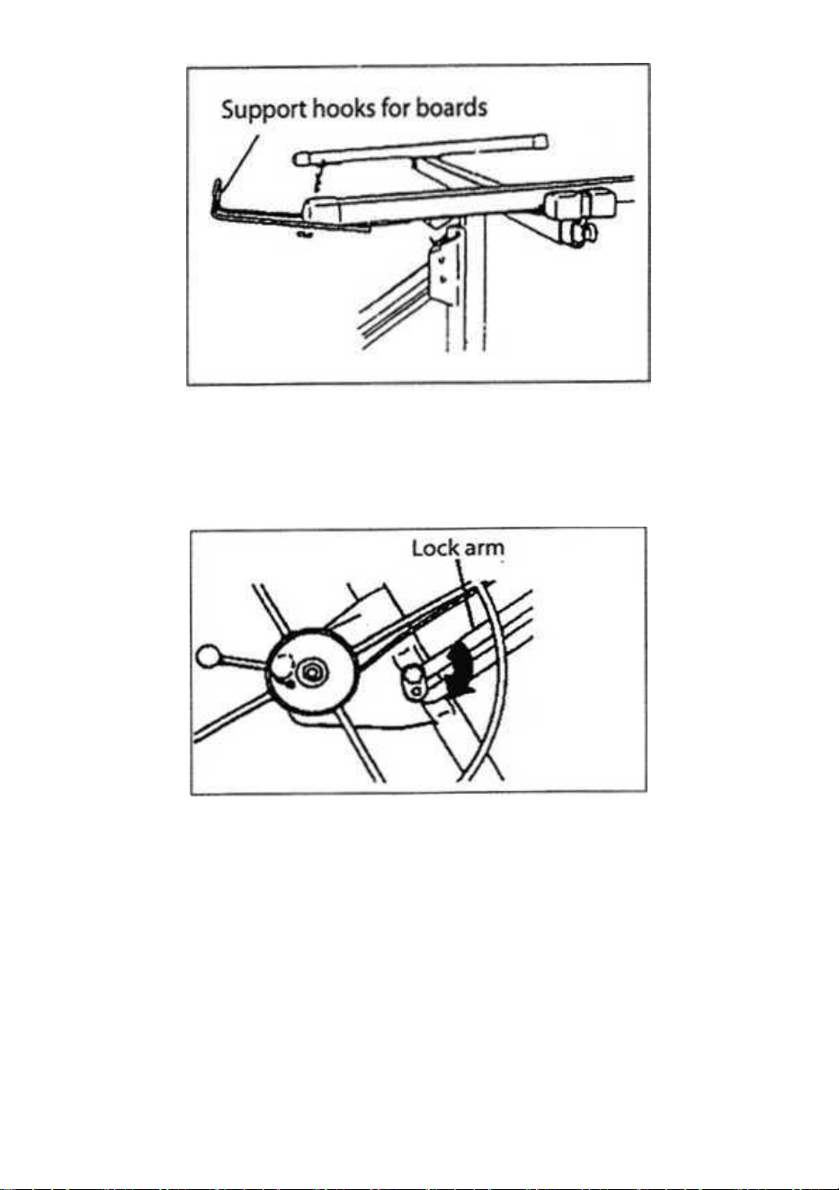
Support hooks for boards
Flip the support hooks on each support arm out to support the covering
board when placed on the cradle or when the cradle is tilted.
In order to avoid damaging the support hooks, push them fully in before
transporting or storing the plasterboard lift.
- 9 -
Lock arm
The lock arm keeps the hoist in the working position (fully extended).
To fold the hoist in towards the frame (when dismantling or for transport),
turn the hoist anticlockwise while lifting the lock arm. When you
reassemble the plasterboard lift, pull the hoist out fully and then push it
back slightly so that it will automatically engage with the lock arm.
Never tighten the nut on the lock arm, or you will be unable to fold the hoist
for transport and storage.
- 10 -
Manufacturer: Shanghaimuxinmuyeyouxiangongsi
Address: Shuangchenglu 803nong11hao1602A-1609shi, baoshanqu,
shanghai 200000 CN.
Imported to AUS: SIHAO PTY LTD. 1 ROKEVA STREETEASTWOOD
NSW 2122 Australia
Imported to USA: Sanven Technology Ltd. Suite 250, 9166 Anaheim
Place, Rancho Cucamonga, CA 91730
REP
UK
YH CONSULTING LIMITED. C/O YH Consulting
Limited Office 147, Centurion House, London
Road, Staines-upon-Thames, Surrey, TW18 4AX
REP
EC
E-CrossStu GmbH
Mainzer Landstr.69,
60329 Frankfurt am Main.