REVISED BULLETIN
SERVICE PARTS LIST
BULLETIN NO.
WIRING INSTRUCTION
DATE
EXAMPLE:
Component Parts (Small #) Are Included
When Ordering The Assembly (Large #).
0
00
SERIAL
NUMBER
SPECIFY CATALOG NO. AND SERIAL NO. WHEN ORDERING PARTS
CATALOG NO.
MILWAUKEE TOOL
l
www.milwaukeetool.com
13135 W. LISBON RD., BROOKFIELD, WI 53005
Drwg. 2
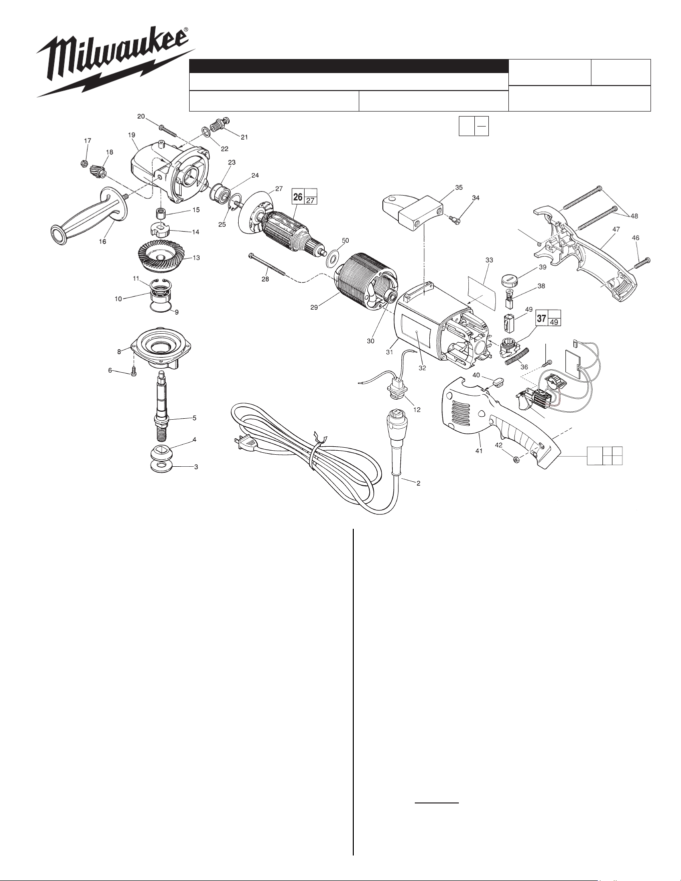
FIG. PART NO. DESCRIPTION OF PART NO REQ.
33 10-98-1800 Warning Label (1)
34 45-04-0720 Shoulder Screw (3)
35 31-70-0140 Tool Rest (1)
36 40-50-7770 Brush Holder Spring (2)
37 22-22-1325 Brush Holder Assembly (2)
38 22-18-0680 Brush Assembly (2)
39 23-44-0210 Brush Retaining Screw (2)
40 42-38-0190 Bumper (1)
41 --------------- Left Handle Half (1)
42 06-55-1050 10-24 Hex Nut (5)
43 06-82-7409 8-16 x 1/2" Slot. Pan Hd. T-20 Screw (1)
44 23-66-1941 Switch with Dial Remote Assembly (1)
46 06-82-2568 10-24 x 7/8" Slot. Pan Hd. T-25 Screw (3)
47 --------------- Right Handle Half (1)
48 06-82-2598 10-24 x 2-3/4" Slot. Pan Hd. T-25 Screw (2)
49 22-20-0660 Brush Tube (2)
50 23-16-1700 Commutator Insulator (1)
57 42-38-0181 Rubber Bumper (2)
58 31-50-0548 Handle/Motor Housing Service Kit (1)
FIG. NOTES:
14,17 Apply Type 277 Red Loctite.
FIG. LUBRICATION:
19 Important! Completely clean out old grease from the
upper gearcase and replace with 1.5 Oz. Type "Y" Grease,
54-38-0027
See Reverse Side
834C
6078
FIG. PART NO. DESCRIPTION OF PART NO REQ.
2 48-76-5010 Quik-Lok Cord Set (1)
3 45-88-8465 Spindle Washer (1)
4 49-05-0060 Spindle Washer - Flange (1)
5 38-50-5645 Spindle Shaft (1)
6 06-82-8864 10-24 x 1/2" Pan Hd. Sems T-25 Screw (4)
8 28-14-1900 Lower Gear Case (1)
9 34-40-1550 1-9/16" O-Ring (1)
10 02-04-1745 Ball Bearing (1)
11 34-80-2960 Retaining Ring - Internal (1)
12 22-56-0679 Blade Housing Assembly (1)
13 32-05-2191 Spiral Bevel Gear (1)
14 42-74-0080 Spindle Locking Cog (1)
15 02-50-2423 Needle Bearing (1)
16 43-62-1265 Side Handle (1)
17 06-57-0500 1/4 - 28 Hex Nut (1)
18 32-60-1286 Spiral Bevel Pinion (1)
19 28-14-2090 Upper Gear Case (1)
20 06-82-7224 10-14 x 1" Pan Hd. Plastite T-25 Screw (4)
21 44-20-0235 Spindle Lock Assembly (1)
22 45-88-5320 Flat Washer (1)
23 34-40-1375 1-1/4" O-Ring (1)
24 02-04-0195 Ball Bearing (1)
25 34-80-2600 Retaining Ring - Internal (1)
26 16-50-1185 120 V. Armature (1)
27 22-84-0710 Fan (1)
28 06-82-7375 8-16 x 2-1/2"
Pan Hd. Plastite T-20 Screw
(2)
29 18-50-0171 120 V. Field (1)
30 02-04-0845 Ball Bearing (1)
31 --------------- Motor Housing (1)
32 12-20-6100 Service Nameplate Kit (1)
D. I. 6000 RPM DIAL SPEED SANDER
54-38-0026
«
«
«
«
«
«
«
«
«
43
44
57
(2x)
31 41
47
58
«= Part number change from previous
service parts list.
Aug. 2022
1
2
3
5
7
9
10
6
4
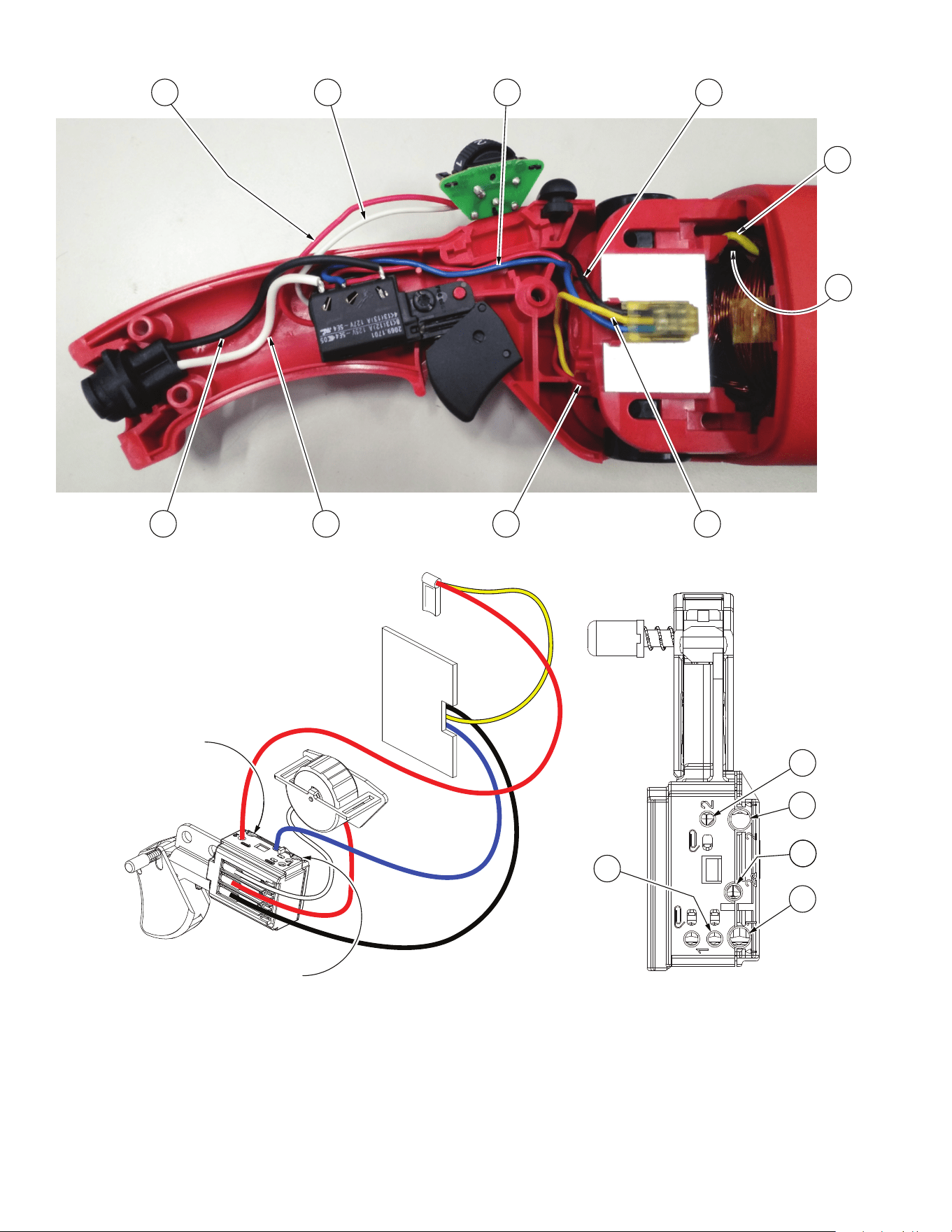
Red wire from
dial to switch
White wire from
dial to switch
Blue wire from
module to switch
Black wire from
module to switch
Black wire from
blade housing
to switch
White wire from
blade housing
to switch
Red wire from
brush to switch
Yellow wire from module
thru trap to lower brush
Yellow field
wire to top
brush
8
Black field
wire (from
other side)
to switch
Note:
Black field wire #8 is placed
in wire traps under wires
#1, #3 and #4.
10
3
9
4
8
Black wire from
blade housing
assembly here
White wire from
blade housing
assembly here