BOAT SWITCH PRE-CONFIGURED DIGITAL SWITCHING SYSTEM
INSTALLATION INSTRUCTIONS
Important Safety Information
WARNING
See the Important Safety and Product Information guide in the product box for product warnings and other
important information.
Garmin
®
strongly recommends using a professional installer with proper knowledge of electrical systems to
install the device. Incorrectly installing the device can result in serious bodily injury and damage to the vessel or
the battery.
CAUTION
Failure to follow these cautions could result in bodily injury damage to the device and/or vessel, or poor product
performance.
This device must be installed according to these instructions.
Disconnect the vessel's power supply before beginning to install this product.
Before applying power to this product, make sure it has been correctly grounded according to the installation
instructions.
You must read all installation instructions before beginning the installation. If you do not understand the
installation needs of this device, or if you experience difficulty during the installation, contact Garmin Product
Support.
Setting up a Garmin Boat Switch
™
Device
Follow these steps to set up a Garmin Boat Switch device on the vessel. Additional information and instructions
are contained in this document for your reference.
You should contact Garmin product support or your Garmin field service engineer (FSE) for assistance or if you
have any questions.
1 Mount the Garmin Boat Switch device (Mounting the Garmin Boat Switch Device, page2).
2 Connect the Garmin Boat Switch device to the NMEA 2000
®
network (NMEA 2000 Network Connection,
page4).
3 Connect the switched devices or circuits to the X1 wiring harness (X1 Wiring Harness, page6) and the X2
wiring harness (X2 Wiring Harness, page9).
4 Connect the Garmin Boat Switch device to power (Connecting to Power, page15).
5 Configure the Garmin Boat Switch device (Configuring the Device, page16).
GUID-A4B2918E-C905-454D-967F-B0B7AB889986 v5April 2022

Mounting Considerations
Selecting the correct mounting location is critical to optimize the performance of the Garmin Boat Switch
device. When selecting a mounting location, observe these considerations.
• You must mount the device in an accessible location.
◦ All of the switches on this device can be activated by pressing buttons on the device directly. Because of
this, the device must be accessible in case there is an issue with switching using the chartplotter.
◦ Many of the settings on this device must be configured by connecting specific wires on the wiring harness
to a ground wire. Because of this the device must be accessible during the configuration process.
◦ This device uses software fuses, and if any of the fuses trip, you may need to reset them by pressing
buttons on the device directly. Because of this, the device must be accessible during use so you can reset
any tripped software fuses when needed.
• You must mount the device in a location where it is not submerged.
• You must mount the device on a flat, vertical mounting surface, with the wire harness connectors pointing
down.
• You must clear mounting surface of dirt, debris, wax, or coatings.
• Mounting hardware is not included with this device. You must provide pan-head screws of the appropriate
length for the mounting surface.
• You should select a location away from sources that can interfere with the device's operation. Sources of
interference may include strong electromagnetic fields, such as power cables and electric motors.
Mounting the Garmin Boat Switch Device
Before you can mount the device, you must select a location in accordance with the mounting considerations.
Mounting hardware is not provided with this device. Before you can mount the device, you must acquire
pan-head screws of the appropriate length for the mounting surface.
NOTICE
Do not use the Garmin Boat Switch device as a template when drilling the mounting holes because drilling
through the mounting holes may damage the device and void the warranty.
Do not apply grease or lubricant to the screws when fastening the device to the mounting surface. Grease or
other lubricants can cause damage to the device housing.
You must select pan-head screws to secure the device. Using countersunk screws can damage the device
housing.
1 With the wiring-harness connectors pointing down, hold the device on a flat, vertical mounting surface and
mark the locations for the pilot holes.
2 Remove the device from the mounting surface.
3 Using a 2mm (
5
/
64
in.) drill bit, drill the pilot holes.
4 Verify that the mounting holes on the device line up with the pilot holes.
5 Fasten pan-head screws (not included) into the bottom two pilot holes , leaving room to attach the device.
2
6 Place the device over the screw heads, and slide it downward to lock it into place .
7 Fasten pan-head screws (not included) into the top two pilot holes .
8 Secure the device to the mounting surface by tightening the four screws until they are snug.
NOTICE
Do not overtighten the screws because it may damage the device housing.
Connection Considerations
You should carefully plan the layout of the device, the power wiring, the NMEA 2000 network, and all switched
devices before making any connections.
When making connections, observe these considerations.
• This device supports a maximum of 50A total for all active channels. When planning switched connections,
consider the power needs of all potential load combinations to ensure that the total active load does not
exceed 50A when in use.
• You must connect both the X1 and X2 wiring harnesses to this device, but you do not have to connect
devices to every wire on the harnesses.
• You must make all bare wire connections using a marine-grade, waterproof connectors or waterproof heat-
shrink.
• You must insulate any unused bare wire connections after completing installation.
• When connecting a device or circuit to the wiring harness, ensure that the power requirements for the device
or circuit do not exceed the rated SW fuse for the channel.
• When extending wires, you must use the appropriate wire gauge as specified for the power wire (Connecting
to Power, page15) and for the individual wires on the wiring harnesses (X1 Wiring Harness, page6, X2
Wiring Harness, page9).
• This device must connect to the same NMEA 2000 network as the chartplotter you want to use for digital
switching (NMEA 2000 Network Connection, page4).
3
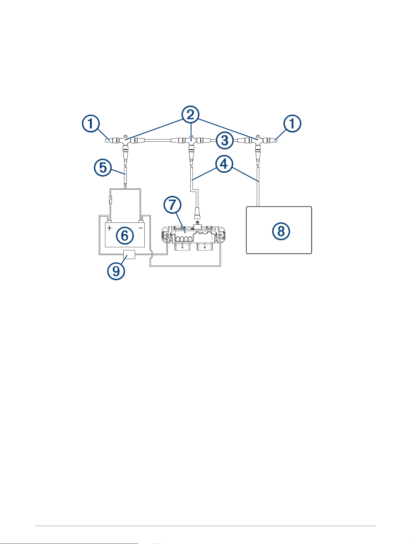
NMEA 2000 Network Connection
This diagram shows a sample installation which you can scale to apply to the NMEA 2000 network on your
vessel. The device must receive power from a dedicated power connection and does not receive power from the
NMEA 2000 network (Connecting to Power, page15).
If you are unfamiliar with the needs of a NMEA 2000 network, you should read the “NMEA 2000 Network
Fundamentals” chapter of the Technical Reference for NMEA 2000 Products. To download the reference, go to
garmin.com/manuals/nmea_2000.
4
Item Description Notes
NMEA 2000 terminator
NMEA 2000 terminators must connect to each end of the NMEA 2000
backbone.
NMEA 2000 T-connector
NMEA 2000 T-connectors must connect to one another using the sides
of each T, and they must connect to NMEA 2000 devices using drop
cables connected to the top of each T.
NMEA 2000 Backbone
NMEA 2000 drop cable
A NMEA 2000 drop cable connects a device to the NMEA 2000 network.
A NMEA 2000 drop cable should not exceed 6m (20ft.).
NMEA 2000 power cable
12 V power source
Garmin Boat Switch device
The Garmin Boat Switch device must connect to both the NMEA 2000
network and to switched devices to function correctly.
Garmin chartplotter
The Garmin chartplotter must have a power connection separate from
the NMEA 2000 network.
Inline 50 A circuit breaker or
fuse
The Garmin Boat Switch must connect to power through a 50 A circuit
breaker or fuse (Connecting to Power, page15).
Connecting Devices to the Wiring Harnesses
You must use the provided wiring harnesses to connect switched devices to the Garmin Boat Switch device.
WARNING
In order to avoid accidental short circuits, disconnect the power supply to the Garmin Boat Switch before
making any connections. Failure to disconnect the power supply could result in serious bodily injury, and/or
damage to the device and/or vessel.
NOTICE
To avoid possible damage to the device, the wiring harness, or the vessel, you should refer to American Boat &
Yacht Council (ABYC) or your local and regional standards when determining the maximum length and gauge of
wire extensions.
NOTE: You can view examples of common wiring installations on the Garmin website. Go to garmin.com
/manuals/boatswitch/.
1 Route appropriately gauged marine-grade, fully-tinned copper wire (not included) from the location of the
device to the switched devices.
NOTE: You should label both ends of the wire so you can easily identify which wires route to which devices.
2 Connect the wire to the wiring harness using appropriately gauged marine-grade connectors.
Because the device is pre-configured, you must connect switched devices to the appropriate wires on the
wiring harness (X1 Wiring Harness, page6), (X2 Wiring Harness, page9).
3 Connect the X1 wiring harnesses to the X1 port on the Garmin Boat Switch device.
4 Connect the X2 wiring harnesses to the X2 port on the Garmin Boat Switch device.
5 Verify the X1 harness is connected to the X1 plug on the Garmin Boat Switch device and the X2 harness is
connected to the X2 plug on the Garmin Boat Switch device.
NOTE: The Garmin Boat Switch device and connected devices will not operate correctly if the plugs are not
connected correctly.
5
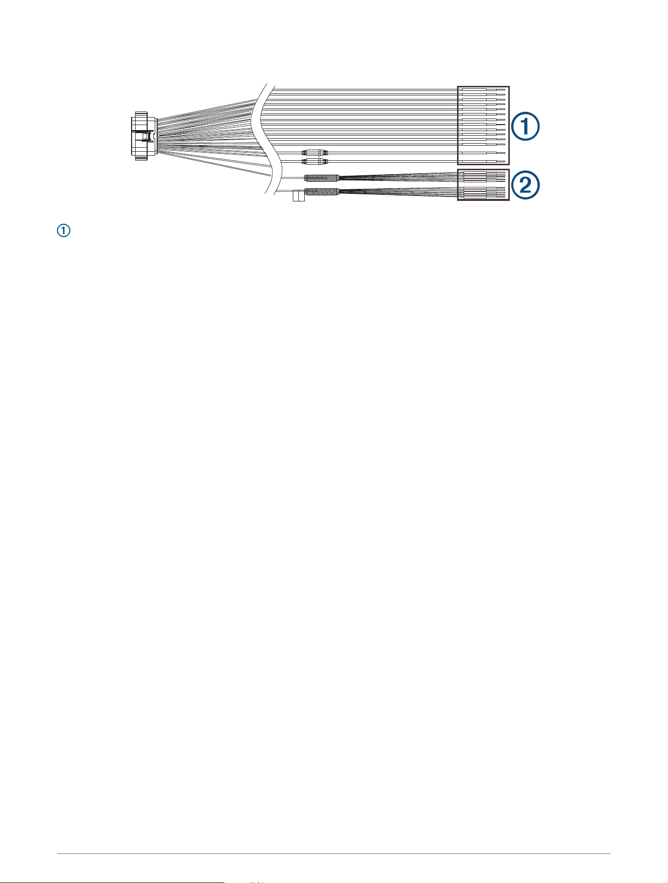
X1 Wiring Harness
X1 Primary Wire Connections
The primary wires on the X1 wiring harness connect to the appropriate devices on the vessel to allow for digital
control or monitoring. When connecting a device or devices to a wire on this harness, you must use the wire
gauge specified in the table at the very minimum. For long wire runs, you should consider using larger-diameter
(smaller gauge number) wire to minimize power loss.
NOTE: You should refer to ABYC or your local and regional standards when determining the maximum length
and gauge of wire extensions.
6

Wire Label Wire Color
Wire
Gauge
Software
Fuse Rating
Wire Function
CH 1-TOGGLE 1(5A) Gray 14AWG 5A
Provides a latching switch output intended
for use with red/green navigation lights
1
.
By default this channel is tied to CH 2-
TOGGLE 2(5A) for navigation-light control
(Navigation and Anchor Light Wiring,
page12).
CH 2-TOGGLE 2(5A) Blue 14AWG 5A
Provides a latching switch output intended
for use with a white navigation/anchor light
1
.
By default this channel is tied to CH 1-
TOGGLE 1(5A) for navigation-light control
(Navigation and Anchor Light Wiring,
page12).
CH 3-TOGGLE 3(5A) Orange 14AWG 5A Provides latching a switch output
1
.
CH 4-TOGGLE 4(5A) Purple 14AWG 5A Provides a latching switch output
1
.
CH 5-TOGGLE 5(5A) Green 14AWG 5A Provides a latching switch output
1
.
CH 6-RES TANK 1 Pink 16AWG N/A
Provides monitoring for tank 1 resistive
sensor.
Must connect to ground using the CH 32
TANK SENSOR GROUND wire on the X2
wiring harness.
CH 7-RES TANK 2 White 16AWG N/A
Provides monitoring for tank 2 resistive
sensor.
Must connect to ground using the CH 32
TANK SENSOR GROUND wire on the X2
wiring harness.
CH 9-TOGGLE 6(10A)
Gray with
black stripe
14AWG 10A Provides a latching switch output
1
.
CH 10-TOGGLE 7(10A)
Blue with
black stripe
14AWG 10A Provides a latching switch output
1
.
CH 11-LIVEWELL(10A)
Orange
with black
stripe
14AWG 10A
Provides a latching switch output for a live-
well pump
1
.
CH 12-BILGE 1
MANUAL(10A)
Brown 14AWG 10A
Provides a latching switch output for a bilge
pump
1
.
CH 13-BILGE 2
MANUAL(10A)
Brown 14AWG 10A
Provides a latching switch output for a bilge
pump
1
.
CH 14-BILGE 1
MONITOR
Brown with
black stripe
16AWG N/A
Input for monitoring bilge pump 1 automatic
operation. Generates an alarm when the
pump runs for longer than 2 min. or is
activated five times within 60 min. (12 Vdc)
CH 15-BILGE 2
MONITOR
Brown with
black stripe
16AWG N/A
Input for monitoring bilge pump 2 automatic
operation. Generates an alarm when the
1
All switches on the Garmin Boat Switch device must be configured in the chartplotter software to function properly (Switch Configuration, page17)
7

Wire Label Wire Color
Wire
Gauge
Software
Fuse Rating
Wire Function
pump runs for longer than 2 min. or is
activated five times within 60 min. (12 Vdc)
X1 Breakout Wire Connections
The breakout wires on the X1 wiring harness allow you to add a physical switch to a device or circuit connected
to a digital switch on the specified primary wires of the X1 and X2 wiring harnesses. Connecting these wires
to the CH 32 TANK SENSOR GROUND wire on the X2 breakout wiring harness through a physical momentary
switch triggers the associated latching, dimming, or momentary switch for devices connected to the correlated
channels on the primary harnesses.
NOTE: Only momentary switches should be used for physical switches. Using physical latching or toggle
switches can override the Garmin Boat Switch device and disable digital switching on that channel through the
connected Garmin chartplotter.
Wire Label
Wire
Color
Wire
Gauge
Wire Function
SWITCH INPUT: CH1
TOGGLE 1 (OPTIONAL)
Black 18AWG
Latching switch input for CH 1-TOGGLE 1(5A) on this
wiring harness.
By default this input is tied to CH 2-TOGGLE 2(5A)
for navigation-light control (Navigation and Anchor Light
Wiring, page12).
SWITCH INPUT: CH2
TOGGLE 2 (OPTIONAL)
Brown 18AWG
Latching switch input for CH 2-TOGGLE 2(5A) on this
wiring harness.
By default this input is tied to CH 1-TOGGLE 1(5A)
for navigation-light control (Navigation and Anchor Light
Wiring, page12).
SWITCH INPUT: CH3
TOGGLE 3 (OPTIONAL)
Red 18AWG
Latching switch input for CH 3-TOGGLE 3(5A) on this
wiring harness.
SWITCH INPUT: CH9
TOGGLE 6 (OPTIONAL)
Orange 18AWG
Latching switch input for CH 9-TOGGLE 6(10A) on this
wiring harness.
SWITCH INPUT: CH10
TOGGLE 7 (OPTIONAL)
Yellow 18AWG
Latching switch input for CH 10-TOGGLE 7(10A) on this
wiring harness.
SWITCH INPUT: CH17 DIM
1 (OPTIONAL)
Black 18AWG
Dimming switch input for CH 17-DIMMABLE 1(10A) on
the X2 wiring harness.
SWITCH INPUT: CH18 DIM
2 (OPTIONAL)
Brown 18AWG
Dimming switch input for CH 18-DIMMABLE 2(10A) on
the X2 wiring harness.
SWITCH INPUT: CH19 DIM
3 (OPTIONAL)
Red 18AWG
Dimming switch input for CH 19-DIMMABLE 3(10A) on
the X2 wiring harness.
SWITCH INPUT:
CH25 MOMENTARY 1
(OPTIONAL)
Orange 18AWG
Momentary switch input for CH 25-MOMENTARY 1
(10A) on the X2 wiring harness.
SWITCH INPUT:
CH26 MOMENTARY 2
(OPTIONAL)
Yellow 18AWG
Momentary switch input for CH 26-MOMENTARY 2
(10A) on the X2 wiring harness.
8
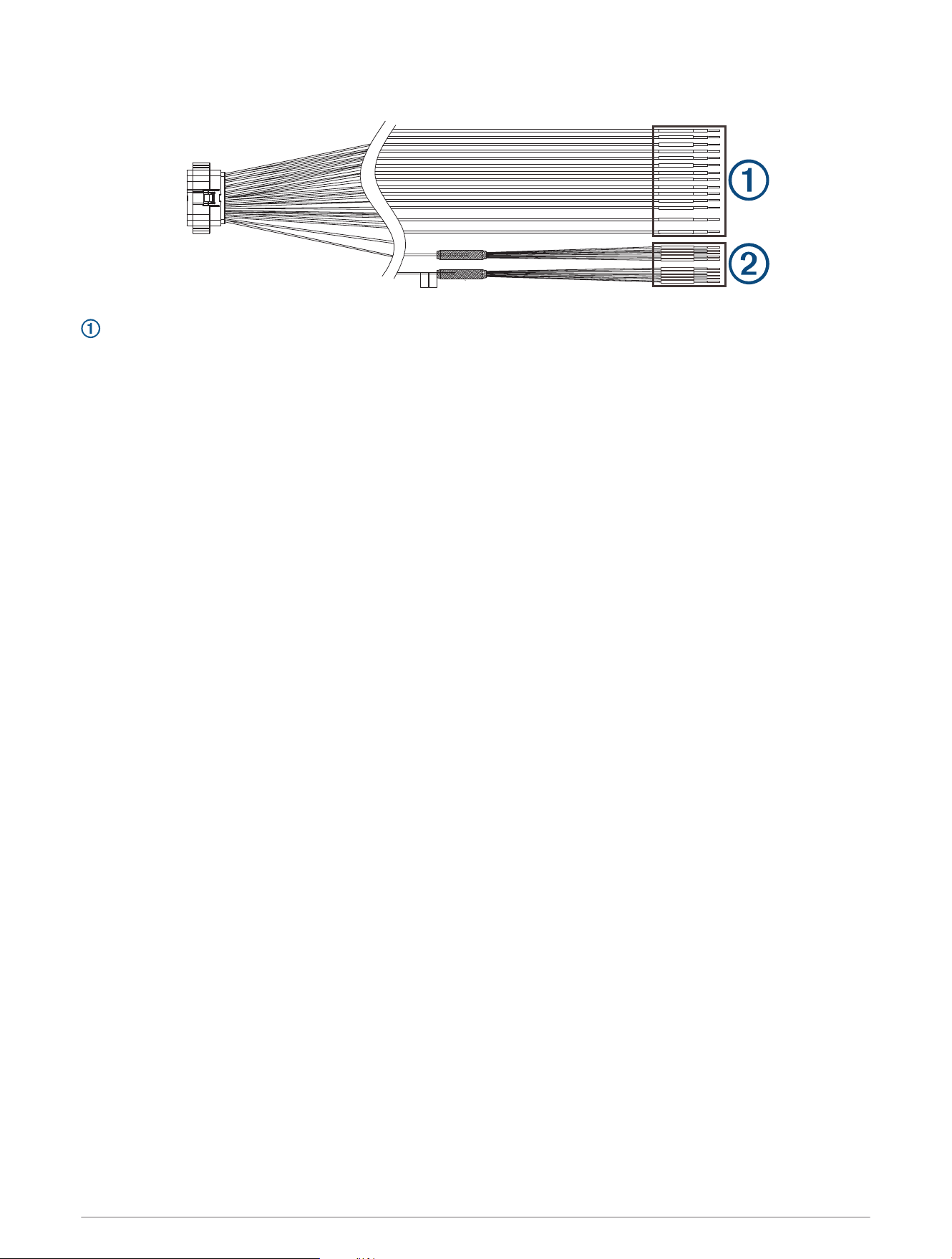
X2 Wiring Harness
X2 Primary Wire Connections
The primary wires on the X2 wiring harness connect to the appropriate devices on the vessel to allow for digital
control or monitoring. When connecting a device or devices to a wire on this harness, you must use the wire
gauge specified in the table at the very minimum. For long wire runs, you should consider using larger-diameter
(smaller gauge number) wire to minimize power loss.
NOTE: You should refer to ABYC or your local and regional standards when determining the maximum length
and gauge of wire extensions.
9

Wire Label Wire Color
Wire
Gauge
Software
Fuse Rating
Wire Function
CH 17-DIMMABLE
1(10A)
Gray 14AWG 10A
Provides a dimmable latching switch
output
1
.
CH 18-DIMMABLE
2(10A)
Blue 14AWG 10A
Provides a dimmable latching switch
output
1
.
CH 19-DIMMABLE
3(10A)
Orange 14AWG 10A
Provides a dimmable latching switch
output
1
.
CH 20-DIMMABLE 4(5A) Purple 14AWG 5A
Provides a dimmable latching switch
output
1
.
CH 21-DIMMABLE 5(5A) Green 14AWG 5A
Provides a dimmable latching switch
output
1
.
CH 22-VOLT TANK 1 Pink 16AWG N/A
Provides monitoring for Tank 1 voltage-
based sensor.
Must connect to ground using the CH 32
TANK SENSOR GROUND wire on the X2
wiring harness.
CH 23-VOLT TANK 2 White 16AWG N/A
Provides monitoring for Tank 2 voltage-
based sensor.
Must connect to ground using the CH 32
TANK SENSOR GROUND wire on the X2
wiring harness.
CH 25-MOMENTARY 1
(10A)
Gray with
black stripe
14AWG 10A Provides a momentary switch output
1
.
CH 26-MOMENTARY 2
(10A)
Blue with
black stripe
14AWG 10A Provides a momentary switch output
1
.
CH 27-MOMENTARY 3
(10A)
Orange with
black stripe
14AWG 10A Provides a momentary switch output
1
.
CH 28-ALWAYS ON(10A)
Purple with
black stripe
14AWG 10A Provides unswitched constant power.
CH 29-ALWAYS ON(10A)
Green with
black stripe
14AWG 10A Provides unswitched constant power.
CH 30-START BATTERY
SENSE (optional)
Yellow with
black stripe
16AWG N/A
Optional connection that monitors start
battery voltage. This information is
provided to the NMEA 2000 network
using PGN 127508.
CH 32 TANK SENSOR
GROUND
Brown with
black stripe
16AWG N/A
Connects to the ground wire from a tank
sensor or physical bypass switch. This
should be used with sensors connected
to channels 6 and 7 on the X1 wiring
harness, channels 22 and 23 on the X2
wiring harness, and all of the breakout
wires for physical switches on both
harnesses.
1
All switches on the Garmin Boat Switch device must be configured in the chartplotter software to function properly (Switch Configuration, page17)
10

X2 Breakout Wire Connections
One grouping of breakout wires on the X2 wiring harness allows you to add a physical switch to a pump
or device connected to a digital switch on the specified primary wires of the X1 and X2 wiring harnesses.
Connecting these wires to the CH 32 TANK SENSOR GROUND wire on the X2 wiring harness through a physical
momentary switch triggers the associated latching, dimming, or momentary switch for devices connected to the
correlated channels on the primary harnesses.
The other grouping of breakout wires on the X2 wiring harness is used when configuring the device. Connecting
these wires to the CH 32 TANK SENSOR GROUND wire on the X2 wiring harness through a physical momentary
switch triggers the associated configuration command.
NOTE: Only momentary switches should be used for physical switches. Using physical latching or toggle
switches can override the Garmin Boat Switch device and disable digital switching on that channel through the
connected Garmin chartplotter.
Wire Label Wire Color
Wire
Gauge
Wire Function
SWITCH INPUT: ALL FUSE
RESET
Black 18AWG
Grounding this wire part of one option for resetting the
software fuses (Resetting All Software Fuses, page22).
SWITCH INPUT: CH12
BILGE 1 (OPTIONAL)
Brown 18AWG
Momentary switch input for a bilge pump connected to
CH 12-BILGE 1 MANUAL(10A) on the X1 wiring harness.
SWITCH INPUT: CH13
BILGE 2 (OPTIONAL)
Red 18AWG
Momentary switch input for a bilge pump connected to
CH 13-BILGE 2 MANUAL(10A) on the X1 wiring harness.
SWITCH INPUT: CH11
LIVEWELL (OPTIONAL)
Orange 18AWG
Momentary switch input for a live-well pump connected
to CH 11-LIVEWELL(10A) on the X1 wiring harness.
SWITCH INPUT:
CH27 MOMENTARY 3
(OPTIONAL)
Yellow 18AWG
Momentary switch input for CH 27-MOMENTARY 3 (10A)
on this wiring harness.
SWITCH INPUT: CALIBRA
TION ENABLE
Black 18AWG
Grounding this wire for 5 seconds places the device into
calibration mode. You must ground this wire again for
five seconds to exit calibration mode (Calibrating the
Tank Sensors, page18).
SWITCH INPUT: STORE
MIN TANK VALUES
Brown 18AWG
Ground this wire when configuring the tank sensors (Cali
brating the Tank Sensors, page18).
SWITCH INPUT: STORE
MAX TANK VALUES
Red 18AWG
Ground this wire when configuring the tank sensors
( (Calibrating the Tank Sensors, page18).
SWITCH INPUT: LIVEWELL
CYCLE ADJ
Orange 18AWG
Ground this wire when configuring the live-well pump
cycle settings (Configuring the Livewell Automatic Pump
Cycle Settings, page19).
SWITCH INPUT: SPARE Yellow 18AWG Unused
11
Navigation and Anchor Light Wiring
NOTICE
It is your responsibility to comply with applicable laws, regulations, and standards related to the use and/or
operation of marine navigation lights. Garmin is not responsible for any fines, penalties, citations, or damages
that may be incurred due to any such lack of compliance.
The first three channels on this device can be used for navigation lighting to satisfy the international regulations
for preventing collisions at sea. Depending on the navigation-lighting configuration on your boat, you can
choose from three different options for activating these lights.
NOTE: You can view examples of common wiring installations including these navigation light options on the
Garmin website. Go to garmin.com/manuals/boatswitch/.
Option A (default): One connection for red/green navigation lights, and one connection for white navigation/
anchor lights (Navigation Lights Option A, page12).
Option B: One connection for red/green/white navigation lights, and one connection for anchor lights
(Navigation Lights Option B, page13).
Option C: One connection for red/green/white navigation lights, one connection for steaming lights, and one
connection for anchor lights (Navigation Lights Option C, page14).
Deactivated: The first three channels are not interconnected, and act as assignable independent switches.
These switches can still be used for lighting, but connected lights must be turned on and off independently of
one another (Configuring The Navigation Light Option, page21).
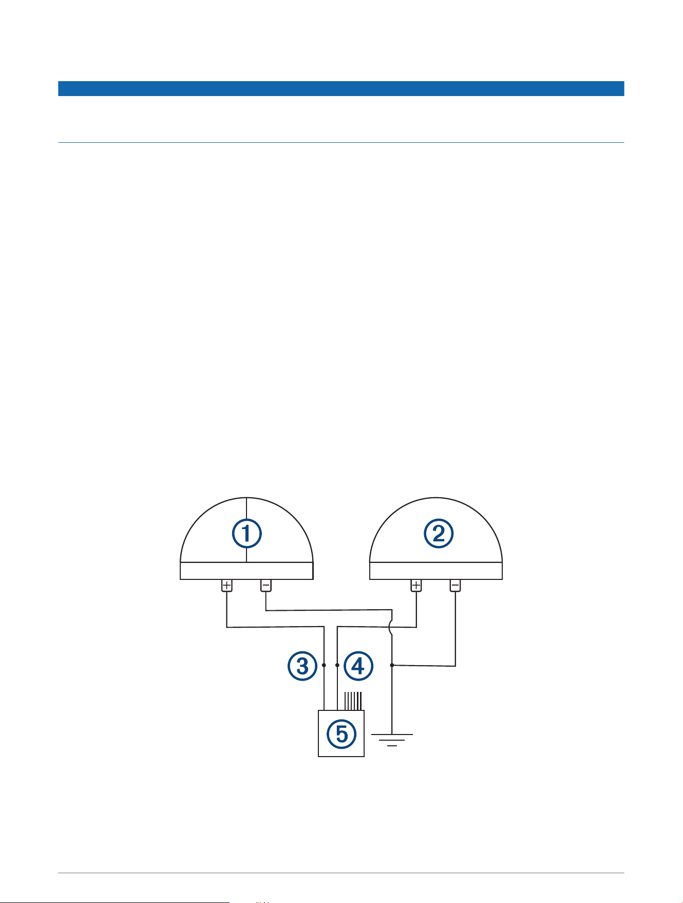
Navigation Lights Option A
By default, the device is set to this option. Channels 1 and 2 are interlocked and intended for one connection to
red and green navigation lights and one connection to white navigation/anchor lights.
When the device is connected properly using this option, it functions as described below.
• When underway, pressing the switch for channel 1 turns on and off both channel 1 and channel 2 (both red
and green navigation lights and white navigation/anchor lights).
• When at anchor, pressing the switch for channel 2 turns on and off channel 2 only (white navigation/anchor
lights), and turns off channel 1 (red and green navigation lights) if it is already on.
12
Red and green navigation lights
White navigation/anchor light(s)
CH 1-TOGGLE 1(5A) wire
CH 2-TOGGLE 2(5A) wire
X1 wiring harness
Power ground
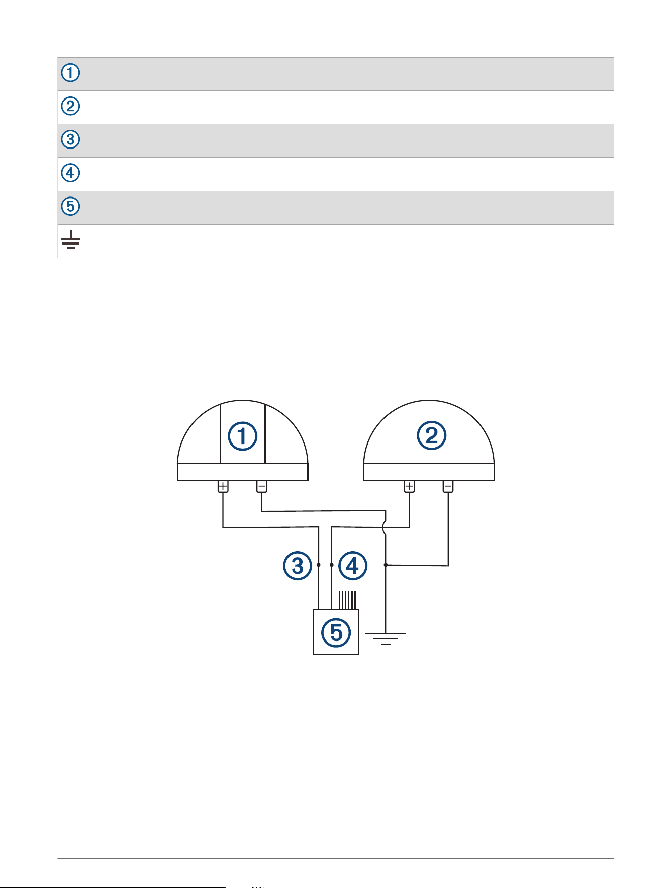
Navigation Lights Option B
You can configure the device so that channels 1 and 2 are interlocked and intended for one connection to
red/green/white navigation lights and one connection to an anchor light.
When the device is connected properly using this option, it functions as described below.
• When underway, pressing the switch for channel 1 turns on and off only channel 1 (red/green/white
navigation lights) and turns off channel 2 (anchor light) if it is already on.
• When at anchor, pressing the switch for channel 2 turns on and off only channel 2 only (anchor light), and
turns off channel 1 (red/green/white navigation lights) if it is already on.
13
Red, green, and white navigation lights
Anchor light
CH 1-TOGGLE 1(5A) wire
CH 2-TOGGLE 2(5A) wire
X1 wiring harness
Power ground
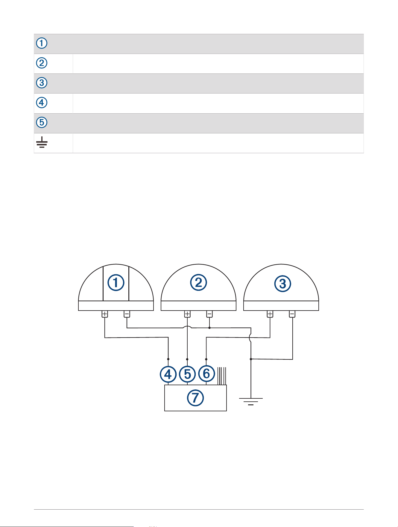
Navigation Lights Option C
You can configure the device so that channels 1, 2, and 3 are interlocked and intended for one connection to
red/green/white navigation lights, one connection to a steaming light, and one connection to an anchor light.
When the device is connected properly using this option, it functions as described below.
• When underway under sail, pressing the switch for channel 1 turns on and off channel 1 (red/green/white
navigation lights), and turns off channel 2 (steaming light) and channel three (anchor light) if either are
already on.
• When underway under engine, pressing the switch for channel 2 turns on and off channel 1 (red/green/white
navigation lights), and channel 2 (steaming light), and turns off channel 3 (anchor light) if it is already on.
• When at anchor, pressing the switch for channel 3 turns on and off only channel 3 (anchor light), and turns off
channel 1 (red/green/white navigation lights) and channel 2 (steaming light) if either are already on.
14
Red, green, and white navigation lights
Steaming light
White anchor light
CH 1-TOGGLE 1(5A) wire
CH 2-TOGGLE 2(5A) wire
CH 3-TOGGLE 3(5A) wire
X1 wiring harness
Power ground
Connecting to Power
WARNING
The wiring (not included) from the power source to the positive terminal of the Garmin Boat Switch device must
run through a 50 A circuit breaker or in-line fuse (not included) as close to the power source as possible. You
must connect the positive wire to the fuse or circuit breaker. Connecting the device to power without a circuit
breaker or in-line fuse may cause a fire if there is a short in the cable, resulting in property damage and/or
serious personal injury.
• If the device is powered by a battery, use a circuit breaker or fuse rated to protect a cable of the gauge used
to connect the device to the battery. See the ABYC or your local and regional standards for the required fuse
or breaker rating.
• If the device is powered by a source other than a battery, use a circuit breaker or fuse rated to the lower of 50
A or the maximum current of the power source.
CAUTION
A power cable is not provided with this device. You must use 6 AWG marine-grade, fully-tinned copper wire
with insulation rated for 105°C (221°F) to connect the device to power and to ground for most installations. For
long wire runs, you should consider using larger-diameter (smaller gauge number) wire to minimize power loss.
Using the improper wire gauge for the power cable can result in damage to the device, the wiring, and the vessel,
as well as causing personal injury.
You should refer to ABYC or your local and regional standards when determining the maximum length and
gauge of wire extensions.
NOTICE
The total maximum output of the Garmin Boat Switch device is 50 A.
Power is supplied to the device through two M6 bolt terminals. You must connect the power and ground wires
to the bolt terminals using marine-grade ring terminals (not included) to ensure a solid power connection.
Connecting bare wires to the bolt terminals may result in loss of power or a short circuit.
1 Route 6 AWG marine-grade, fully-tinned copper wire (not included) to the device and to a ground location on
the boat, and select an option:
• Install a properly rated in-line fuse on the power wire as close to the power source as possible.
• Identify or install a circuit breaker, as close to the power source as possible, for use with the power wire.
2 Install marine-grade ring terminals on both the power and ground wires.
3 Lift the protector covering the positive terminal.
15
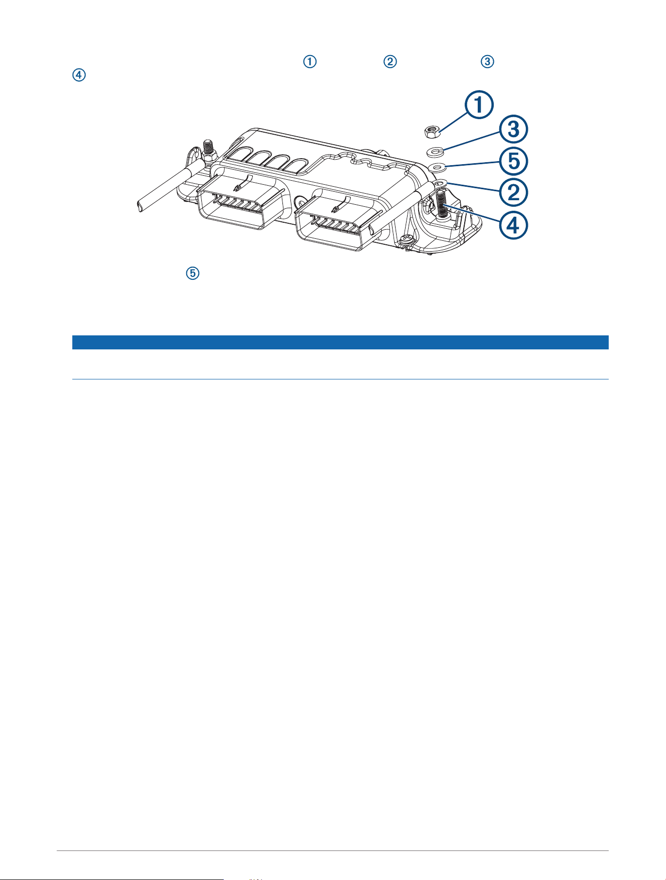
4 Using a 10mm (
3
/
8
in.) socket, remove the nut , lock washer , and flat washer from the terminal bolt
.
5 Place the ring terminal at the end of the positive power wire on the terminal bolt.
6 Place the washer, lock washer, and nut on the terminal bolt.
7 Using a 10mm (
3
/
8
in.) wrench or socket, tighten the nut to a torque of 4.5 Nm to secure the power wire to
the terminal bolt.
NOTICE
Do not overtighten the nut. Overtightening the nut can break the terminal bolt, and a broken terminal bolt
cannot be used or repaired.
8 Lower the protector to cover the positive terminal.
9 Repeat steps 3 through 8 for the negative terminal and the 6 AWG ground wire (not included).
Configuring the Device
Some digital switches must be configured through a Garmin chartplotter before use. You must connect all
switches and switched devices to the Garmin Boat Switch device and power before configuring them using a
Garmin chartplotter connected to the same NMEA 2000 network as the Garmin Boat Switch device.
Accessing Digital Switching
Digital switching is controlled through a Garmin chartplotter connected to the same NMEA 2000 network as the
Garmin Boat Switch device.
NOTE: Some switches only appear when the Garmin Boat Switch device is in calibration mode (Calibrating the
Tank Sensors, page18). You may need to add a page to see new switches after adding a device to the wiring
harness or entering calibration mode (Adding a Switch Page, page16).
From a Garmin chartplotter connected to the same NMEA 2000 network as the Garmin Boat Switch device,
select Vessel > Switching.
Adding a Switch Page
You may need to add a page to see new switches after adding a device to the wiring harness or entering
calibration mode.
From a Garmin chartplotter connected to the same NMEA 2000 network as the Garmin Boat Switch device,
select Vessel > Switching > Options > Setup > Add Page.
16

Switch Configuration
By default, the Garmin chartplotter software is configured so that activating a switch on the chartplotter
screen sends a latching signal a connected digital switching device. Because the Garmin Boat Switch device is
designed to provide both latching and momentary switches within the switching device, the chartplotter must
be configured so that a momentary signal is sent to the Garmin Boat Switch device instead. This allows the
Garmin Boat Switch device to activate the appropriate switch type (either latching or momentary) within the
device based upon the channel.
You must configure all of the following switches as momentary in the chartplotter software for proper operation
(Configuring a Switch as Momentary, page17).
Switch Number Switch Name/Wire Label
1 CH 1-TOGGLE 1(5A)
2 CH 2-TOGGLE 2(5A)
3 CH 3-TOGGLE 3(5A)
4 CH 4-TOGGLE 4(5A)
5 CH 5-TOGGLE 5(5A)
9 CH 9-TOGGLE 6(10A)
10 CH 10-TOGGLE 7(10A)
11 CH 11-LIVEWELL(10A)
12 CH 12-BILGE 1 MANUAL(10A)
13 CH 13-BILGE 2 MANUAL(10A)
17 CH 17-DIMMABLE 1(10A)
18 CH 18-DIMMABLE 2(10A)
19 CH 19-DIMMABLE 3(10A)
20 CH 20-DIMMABLE 4(5A)
21 CH 21-DIMMABLE 5(5A)
25 CH 25-MOMENTARY 1 (10A)
26 CH 26-MOMENTARY 2 (10A)
27 CH 27-MOMENTARY 3 (10A)
Configuring a Switch as Momentary
All latching and momentary channels on the Garmin Boat Switch device must be configured in the chartplotter
software as momentary switches for proper operation.
1 From a Garmin chartplotter connected to the same NMEA 2000 network as the Garmin Boat Switch device,
select Options > Settings > My Vessel > Switching > NMEA Standard.
2 Select the switch number.
3 Select Configuration > Momentary.
17

Calibrating the Tank Sensors
The minimum and maximum fluid levels must be configured for the tank sensors to function properly.
NOTE: To calibrate the sensors, you must connect specific wires in one of the breakout cables in the X2 wiring
harness to a common ground as directed (X2 Wiring Harness, page9). You can connect these wires to ground
through physical momentary switches for convenience.
1 Ensure all of fhe tank sensors are properly connected.
2 Connect the SWITCH INPUT: CALIBRATION ENABLE wire to a common ground for five seconds.
The screen displays Tank sensor calibration mode activated.
3 Set all of the tank sensors to the minimum fill position, and connect the SWITCH INPUT: STORE MIN TANK
VALUES wire to a common ground for three seconds.
The screen displays Tank sensor calibration: Min values stored.
4 Set all of the tank sensors to the maximum fill position, and connect the SWITCH INPUT: STORE MAX TANK
VALUES wire to a common ground for three seconds.
The screen displays Tank sensor calibration: Max values stored.
5 Connect the SWITCH INPUT: CALIBRATION ENABLE wire to a common ground for five seconds.
The screen displays Tank sensor calibration mode deactived.
NOTE: Calibration mode automatically deactivates after 10 minutes if no calibration wires are connected to
ground.
Selecting the Tank Fluid Type
The fluid type must be defined for each connected tank sensor using this procedure. The fluid level PGN is not
transmitted for unconfigured or incorrectly configured tank sensor channels. The fluid type must be defined for
all of the following channels if you connected sensors to the device.
• CH 6-RES TANK 1 (Resistive Tank Sensor 1 (Channel 6), page18)
• CH 7-RES TANK 2 (Resistive Tank Sensor 2 (Channel 7), page19)
• CH 22-VOLT TANK 1 (Voltage Tank Sensor 1 (Channel 22), page19)
• CH 23-VOLT TANK 2 (Voltage Tank Sensor 2 (Channel 23), page19)
1 Ensure all of the tank sensors are properly connected to the appropriate wiring harness.
2 Connect the SWITCH INPUT: CALIBRATION ENABLE wire to a common ground for five seconds.
The screen displays Tank sensor calibration mode activated, and switches 100 through 119 appear on the
Garmin chartplotter.
3 Select the appropriate switch for the tank sensor channel and fluid type.
The screen displays a confirmation message.
4 Repeat the previous step for each tank sensor you need to configure.
5 Connect the SWITCH INPUT: CALIBRATION ENABLE wire to a common ground for five seconds.
The screen displays Tank sensor calibration mode deactived.
NOTE: Calibration mode automatically deactivates after 10 minutes if no calibration switches are used. The
chartplotter must be power cycled to hide the calibration switches.
Resistive Tank Sensor 1 (Channel 6)
Device Switch NMEA 2000 Fluid Type NMEA 2000 PGN NMEA 2000 Instance
100 Fuel (Default) 127505 0
101 Fresh Water 127505 0
102 Waste Water 127505 0
103 Black Water 127505 0
104 Live Well 127505 0
18

Resistive Tank Sensor 2 (Channel 7)
Device Switch NMEA 2000 Fluid Type NMEA 2000 PGN NMEA 2000 Instance
105 Fuel (Default) 127505 1
106 Fresh Water 127505 1
107 Waste Water 127505 1
108 Black Water 127505 1
109 Live Well 127505 1
Voltage Tank Sensor 1 (Channel 22)
Device Switch NMEA 2000 Fluid Type NMEA 2000 PGN NMEA 2000 Instance
110 Fuel (Default) 127505 2
111 Fresh Water 127505 2
112 Waste Water 127505 2
113 Black Water 127505 2
114 Live Well 127505 2
Voltage Tank Sensor 2 (Channel 23)
Device Switch NMEA 2000 Fluid Type NMEA 2000 PGN NMEA 2000 Instance
115 Fuel (Default) 127505 3
116 Fresh water 127505 3
117 Waste water 127505 3
118 Black water 127505 3
119 Live well 127505 3
Configuring the Livewell Automatic Pump Cycle Settings
When activated, a connected livewell pump runs for 1 minute and stops. By default, this device activates the
livewell every 5 minutes, and the activation cycle time can be configured. You can change this value to 1, 3, 5, 7,
9 11, 13, or 15 minutes.
NOTE: You can bypass this activation cycle and set the pump to run continuously by holding the livewell switch
on the Garmin chartplotter for 3 seconds. When bypassed, the pump runs continuously until stopped.
1 Connect the SWITCH INPUT: LIVEWELL CYCLE ADJ wire to a common ground for three seconds.
The runtime-cycle setting changes to the next higher delay. The screen displays the new time between
cycles.
2 Repeat the previous step to increase the delay up to a maximum of 15 minutes.
NOTE: When the live-well pump cycle is set to 15 minutes, you must connect the SWITCH INPUT: LIVEWELL
CYCLE ADJ wire to a common ground for three seconds to set the runtime to back to 1 minute.
19

Naming a Switch
You can provide a custom name to be used instead of the default name for each switch.
1 From a Garmin chartplotter connected to the same NMEA 2000 network as the Garmin Boat Switch device,
select Options > Settings > My Vessel > Switching > NMEA Standard.
2 Select the switch number.
3 Select Name > Change Name.
4 Enter a new name.
5 Select Done.
Labeling a Switch
You can provide a custom label for each switch. The switch label is separate from the switch name.
1 From a Garmin chartplotter connected to the same NMEA 2000 network as the Garmin Boat Switch device,
select Options > Settings > My Vessel > Switching > NMEA Standard.
2 Select the switch number.
3 Select Label > Edit Label.
4 Enter a new label.
5 Select Done.
Showing and Hiding Switches
You can select which switches are hidden or displayed on the Garmin chartplotter.
1 From a Garmin chartplotter connected to the same NMEA 2000 network as the Garmin Boat Switch device,
select Options > Settings > My Vessel > Switching > NMEA Standard.
2 Select the switch number.
3 Select Visibility to show or hide the switch.
Using the Bilge Pump Switches
You can manually operate connected bilge pumps by using switches 12 and 13 on the Garmin chartplotter.
1 From a Garmin chartplotter connected to the same NMEA 2000 network as the Garmin Boat Switch device,
select Vessel > Switching.
2 Select an option:
• Press and hold the bilge pump switch for one second to run the bilge pump for 2 minutes.
• Press and hold the bilge pump switch for three seconds to run the bilge pump continuously.
NOTE: Your Garmin chartplotter notifies you every 5 minutes while continuous mode is active.
Using Dimmable Lights
You can operate connected dimmable lights by using switches 17 through 21 on the Garmin chartplotter.
1 From a Garmin chartplotter connected to the same NMEA 2000 network as the Garmin Boat Switch device,
select Vessel > Switching.
2 Select an option:
• Press a dimmable light switch to turn a light on or off.
NOTE: The light turns on at the dim level set when the light was last turned off.
• With a light on, press and hold a dimmable light switch dim the light, and release to stop dimming.
• With a light off, press and hold a dimmable light switch to turn on the light at 100% brightness.
20

Configuring The Navigation Light Option
By default, channels 1 and 2 are interlocked for navigation lighting to satisfy the international regulations for
preventing collisions at sea (Navigation and Anchor Light Wiring, page12). Depending on the lighting specifics
of your boat, you may need to configure the Garmin Boat Switch device to use the wiring option you that applies
to your installation type.
If you do not intend to connect navigation and anchor lights to the device, you can configure channels 1 and 2 to
operate independently as normal latching switches.
1 From a Garmin chartplotter connected to the same NMEA 2000 network as the Garmin Boat Switch device,
select Vessel > Switching.
2 Press and hold switch 1 for 5 seconds.
Switch 1 starts flashing.
3 Press and hold switch 2 for 5 seconds.
The switch stops flashing, and a message confirms the newly selected wiring option.
4 Repeat the previous two steps until the device is configured for the wiring option that applies to your
installation type.
NOTE: After selecting option C, the next configuration option in the cycle deactivates the interlocks so that
channels 1, 2, and 3 operate independently as normal latching switches.
Manually Operating the Device
You can directly control some digital switches using the hard keys on the Garmin Boat Switch device. You do
not need a Garmin chartplotter connection for manual switching.
NOTE: Manually activating or deactivating digital switches overrides the Garmin chartplotter digital switching
page. You must clear all manual overrides before you can use the switches on the digital switching page on the
Garmin chartplotter (Manually Resetting Switches, page22).
Manually Activating Switches
You can manually activate individual switches on the Garmin Boat Switch device using the device hard keys.
1 On the Garmin Boat Switch device, press .
The screen displays SEL.
2 Press to select the channel you want to activate.
3 Hold MAN ON/MAN OFF for two seconds.
The selected channel is manually overridden and active. The green channel indicator LED blinks rapidly, and
the screen displays ON.
Manually Deactivating Switches
You can manually deactivate individual switches on the Garmin Boat Switch device using the device hard keys.
1 On the Garmin Boat Switch device, press .
The screen displays SEL.
2 Press to select the channel you want to deactivate.
3 Hold MAN ON/MAN OFF for five seconds.
The selected channel is manually overridden and deactivated. The red channel indicator LED blinks rapidly,
and the screen displays OFF.
21

Manually Resetting Switches
You must manually reset the manually operated switches on the Garmin Boat Switch device to reenable digital
switch controls through a Garmin chartplotter. On the device, the indicator LEDs for manually operated channels
rapidly blink green or red.
1 Press on the Garmin Boat Switch device.
The screen displays SEL.
2 Press to select the channel you want to reset.
3 Hold RESET/AUTO for two seconds.
The selected channel resets. The channel indicator LED stops rapidly blinking red or green.
Software Fuses
The Garmin Boat Switch device use software fuses to protect connected devices and cables. A Garmin
chartplotter connected to the same NMEA 2000 network as the Garmin Boat Switch device notifies you when a
software fuse has been tripped. A tripped fuse in indicated directly on the Garmin Boat Switch device with a red
continuance channel LED indicator on the top of the Garmin Boat Switch device.
Resetting All Software Fuses
This device contains software fuses to protect each channel. You can use various methods to reset one or more
of the software fuses if they trip.
• From a Garmin chartplotter connected to the same NMEA 2000 network as the Garmin Boat Switch device,
select software switch 200 for one second to acknowledge the fuse alarm, then select it again to reset all
tripped fuses.
• Connect the SWITCH INPUT: ALL FUSE RESET wire on the X2 wiring harness to a common ground for one
second to acknowledge the fuse alarm, and connect it to a common ground for one second again to reset all
tripped fuses.
Resetting Individual Software Fuses
You can reset individual software fuses on the Garmin Boat Switch device if one or more of the software fuses
trip. When the red channel indicator LED is solid, it indicates the software fuse for that channel has tripped and
must be reset.
1 Press on the Garmin Boat Switch device.
The screen displays SEL.
2 Press to select the channel of the fuse you want to reset.
3 Hold RESET/AUTO for two seconds.
The selected fuse resets. The solid red channel indicator LED turns off.
22

Specifications
Temperature range From -20° to 55°C (from -4° to 131°F)
Material Polycarbonate
Water rating IEC 60529 IPX65
1
Dimensions (W × H × D) 229 × 106 × 41mm (9 × 4
3
/
16
× 1
5
/
8
in.)
Weight 400g (14.08oz.)
Input voltage From 0 to 16 Vdc
NMEA 2000 LEN @ 9 Vdc 0
Fuse 50A
Compass-safe distance 5cm (2in.)
Max. power usage at 12Vdc 50 A
Typical current draw at 12Vdc Approximately 65mA
NMEA 2000 PGN Information
Transmit and Receive
PGN Description
127501 Binary switch
127502 Binary switch
127505 Fluid level
127508 Battery status
1
The device withstands incidental exposure to water of up to 1m for up to 30min. For more information, go to www.garmin.com/waterrating.
23

Garmin Boat Switch LED Codes
The color and blink sequence of the status LEDs on the Garmin Boat Switch device indicate its operational
status and the status of in-use and overridden switches.
LED Label LED Color LED State Status
Green Slow blinking The Garmin Boat Switch device is connected to power.
COM Green Rapid blinking
The Garmin Boat Switch device is connected to the NMEA 2000
network. The blink interval changes based on the amount of data being
transferred.
COM Red Solid
The Garmin Boat Switch is not connected to the NMEA 2000 network.
Indicates a connection or communication failure with the NMEA 2000
network.
1-31 Green Solid The designated channel switch is active.
1-31 Green Slow blinking The designated channel switch is selected.
1-31 Green Rapid blinking The designated channel switch is manually activated.
1-31 Red Rapid blinking The designated channel switch is manually deactivated.
1-31 Red Solid The designated channel switch has tripped a software fuse.
Display Codes
The characters shown on the screen of the Garmin Boat Switch device indicate its operational status.
Display Code Status
SEL The Garmin Boat Switch device is in manual selection mode.
CUA The Garmin Boat Switch device is operating normally.
C01-C29 The designated channel switch is selected.
ON The designated channel switch is manually activated.
OFF The designated channel switch is manually deactivated.
ddd The Garmin Boat Switch device is exiting manual selection mode.
© 2021–2022 Garmin Ltd. or its subsidiaries
Garmin
®
, Garmin Boat Switch
™
, and the Garmin logo are trademarks of Garmin Ltd. or its subsidiaries, registered in the USA and other countries. These trademarks may
not be used without the express permission of Garmin.
Molex
®
is a registered trademark of Molex, LLC in the United States of America and may be registered in other countries. NMEA 2000
®
and the NMEA 2000 logo are
registered trademarks of the National Marine Electronics Association. Wi‑Fi
®
is a registered mark of Wi-Fi Alliance Corporation. Windows
®
is a registered trademark of
Microsoft Corporation in the United States and other countries.
航海網路設備
Garmin Corporation
連絡地址
製造銷售:台灣國際航電股份有限公司
聯絡地址:新北市汐止區樟樹二路 68 號
電 話:(02)2642-8999
客服專線:(02)2642-9199
© 2021–2022 Garmin Ltd. or its subsidiaries
support.garmin.com