
Technical Support and E-Warranty Certificate www.vevor.com/support
HVAC AIR PURIFIER
MODEL:2112-UV36/2006-UV9X2/2112-UV36X2
We continue to be committed to provide you tools with competitive price.
"Save Half", "Half Price" or any other similar expressions used by us only
represents an estimate of savings you might benefit from buying certain tools
with us compared to the major top brands and does not necessarily mean to cover
all categories of tools offered by us. You are kindly reminded to verify carefully
when you are placing an order with us if you are actually Saving
Half in comparison with the top major brands.


1
Model:2112-UV36/2006-UV9X2/2112-UV36X2
NEED HELP? CONTACT US!
Have product questions? Need technical support? Please feel free to
contact us:
Technical Support and E-Warranty Certificate
www.vevor.com/support
This is the original instruction, please read all manual instructions
carefully before operating. VEVOR reserves a clear interpretation of our
user manual. The appearance of the product shall be subject to the
product you received. Please forgive us that we won't inform you again if
there are any technology or software updates on our product.
HVAC AIR PURIFIER

2
SAFETY INSTRUCTIONS
1.Please read and understand this manual carefully before using the HVAC
Air Purifier .
2.The installation should be done by an adult, and children should not use
it without supervision.
3.UV lights are harmful to exposed skin and eyes, causing temporary or
permanent blindness. Never look straight at the UV light.
4.Disconnect the power before installing or replacing the UV bulb,
otherwise may cause shock and death.
5.Please wear gloves and install the HVAC Air Purifier to avoid cuts during
installation.
6.Transportation Attention : During transportation, the package should be
upright, handled with care,prevent strong impact,vibration, extrusion.
7.Do not modify the unit in any way. Any modification could damage the
device or render it dangerous to others.
8.Repair or maintenance should only be carried out by a qualified person.
9.Only the rated voltage specified in this manual can be used.
10.Do not use this product in the kitchen, where the oily fume may shorten
the lifetime of the lamps.
11.Do not use this product in acidic, alkaline or other organic gas area
where may cause fire.
12.Do not use this product in flammable and explosive places, otherwise it
will cause fire.
13.The product can only be disassembled after the product is closed for 15
minutes.
14.The lamp tube contains mercury and must be properly handled.
15.Do not clean up the broken lamps with a vacuum cleaner.
16.The product is not waterproof, can not be the product to be installed in a
humidifier or other wet environment.

3
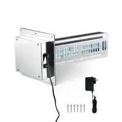
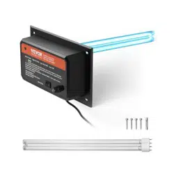
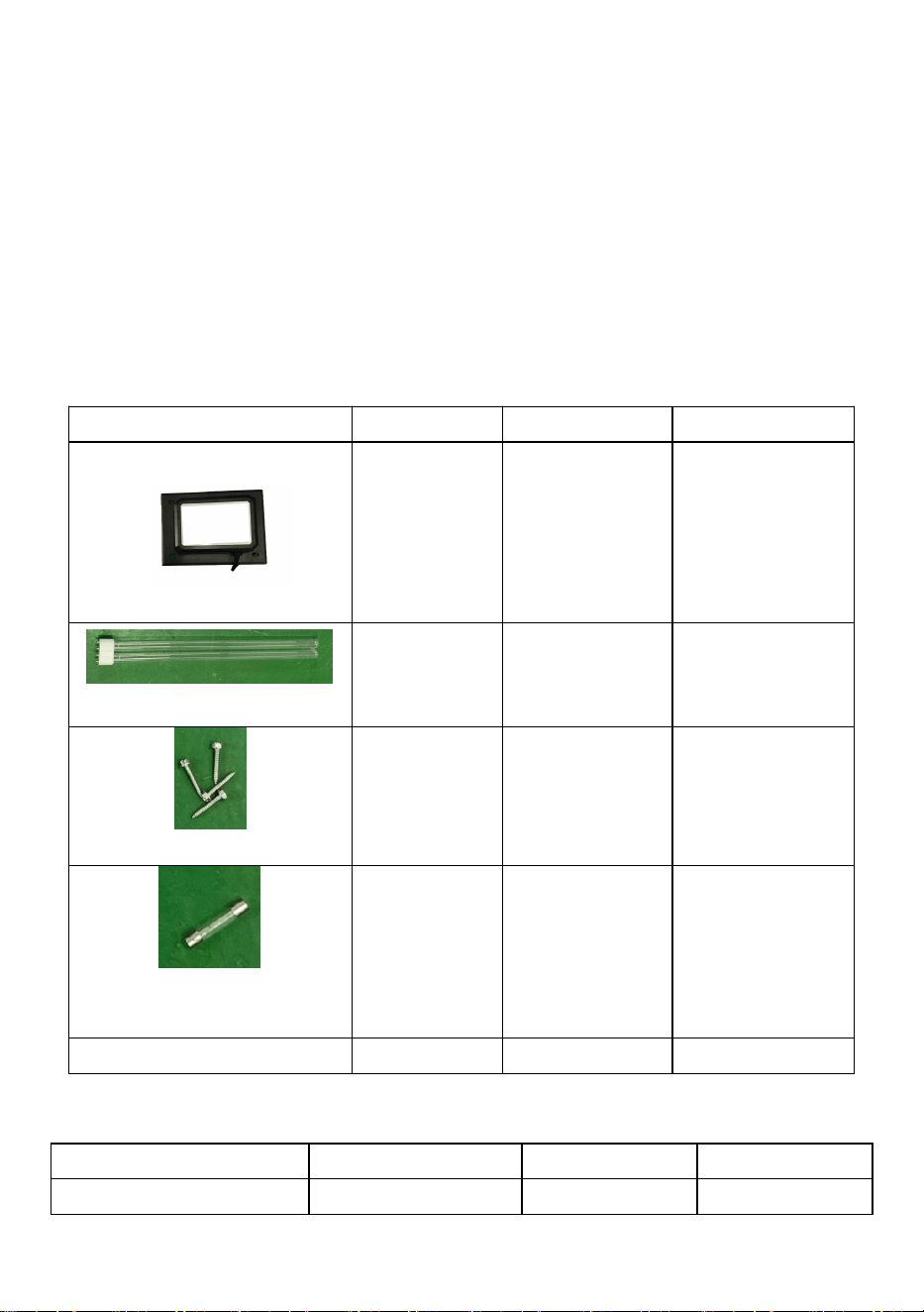
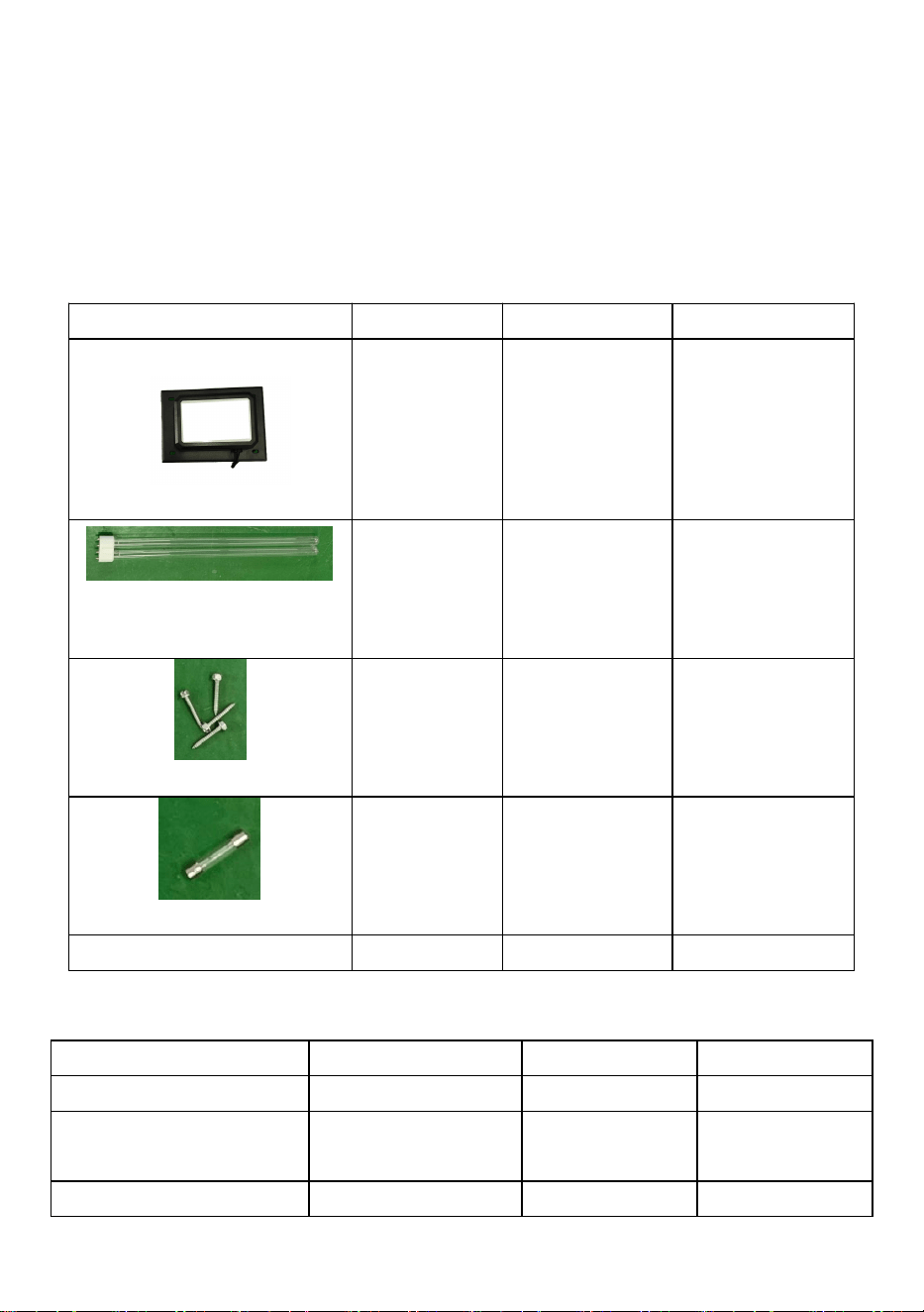
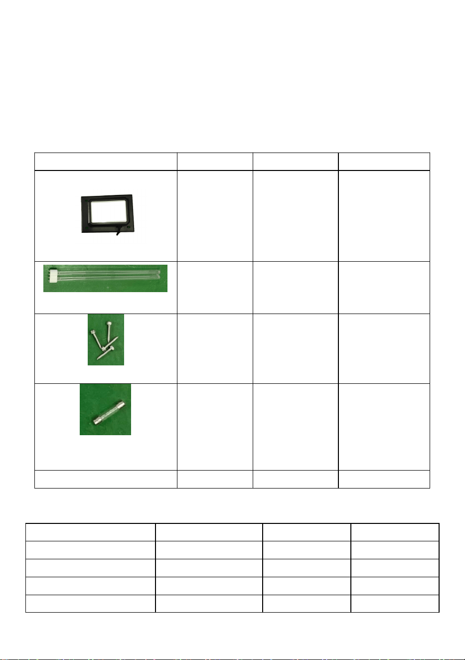
List of kit parts
Model
2112-UV36
2006-UV9X2
2112-UV36X2
UV Unit
1pc
1pc
1pc
UV lamp bulb
2pcs
4pcs
4pcs
screw
4pcs
4pcs
4pcs
Spare the 2A fuse
1pc
/
1pc
Positioning template
1pc
1pc
1pc
PARAMETER LIST
Model
2112-UV36
2006-UV9X2
2112-UV36X2
Power
36W
18W
72
Lights tube length
411mm
145mm
411mm
Light wavelength
254nm
254nm
254nm
UV lifetime
13000hours
13000hours
13000hours
Assembly lamp tube
1pc
2pcs
2pcs
Standby lamp tube
1pc
2pcs
2pcs
American-Standard
Input
AC120V 60Hz
AC120V 60Hz
AC120V 60Hz
European version Input
AC230V 50Hz
AC230V 50Hz
AC230V 50Hz
Effective area
1500 ft²
600 ft²
2400 ft²
4
Note:Each model of rated power supply has AC120V and AC230V. Note
the voltage and frequency information on the product nameplate.
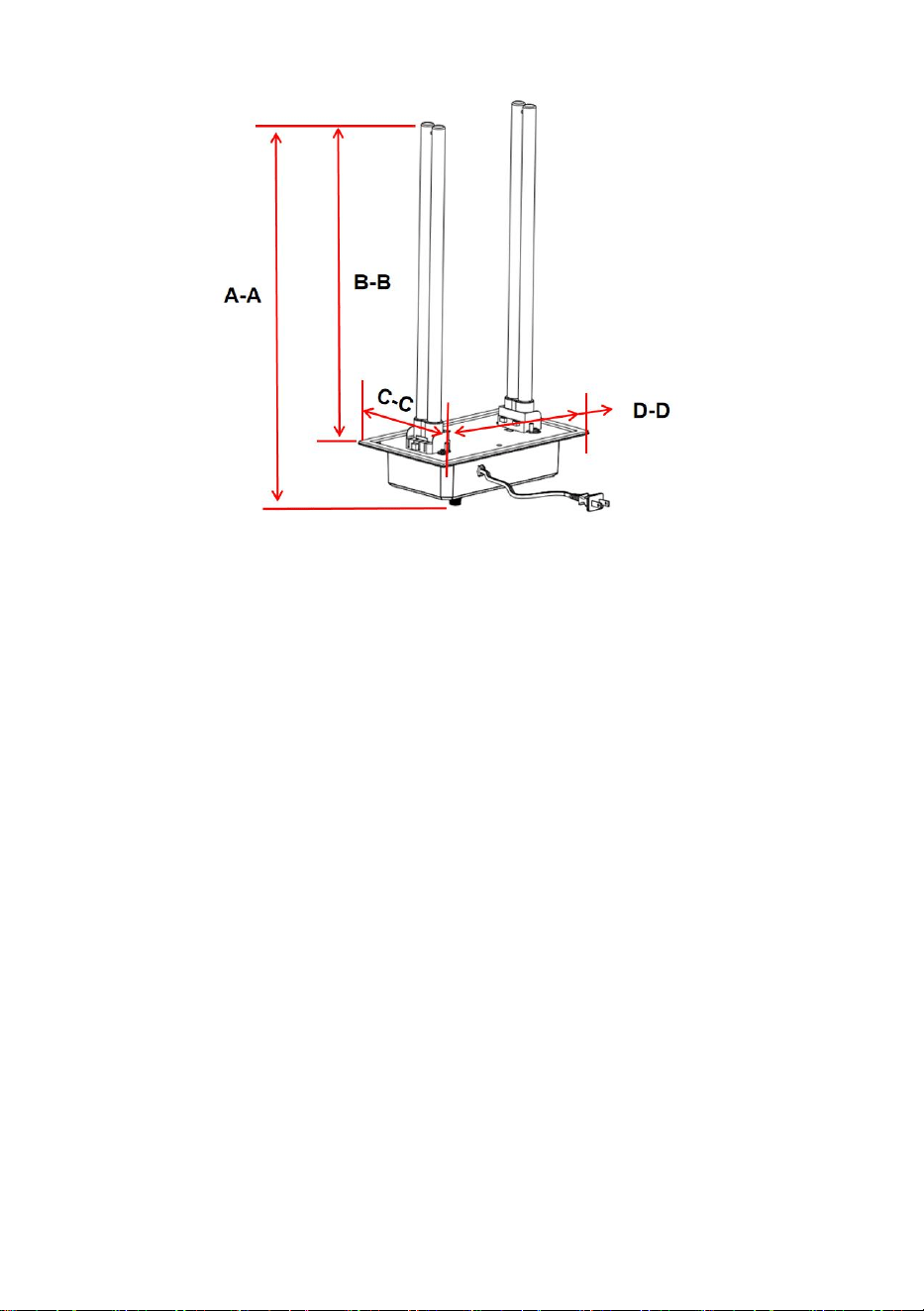
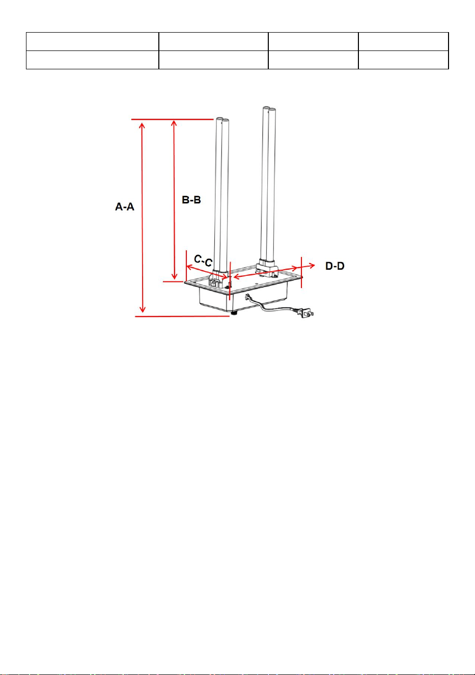
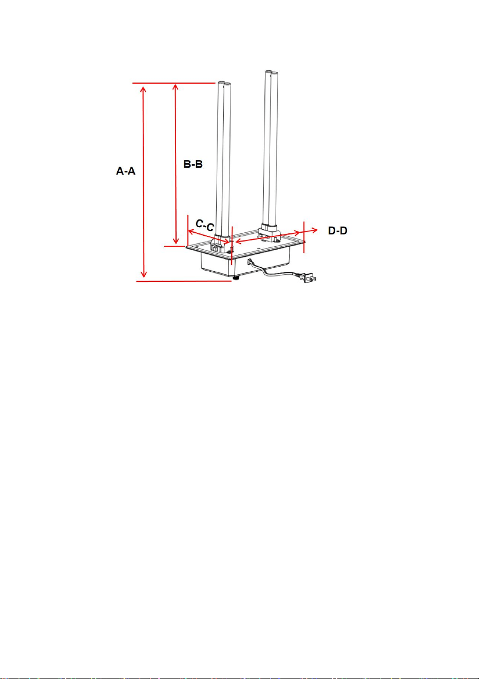
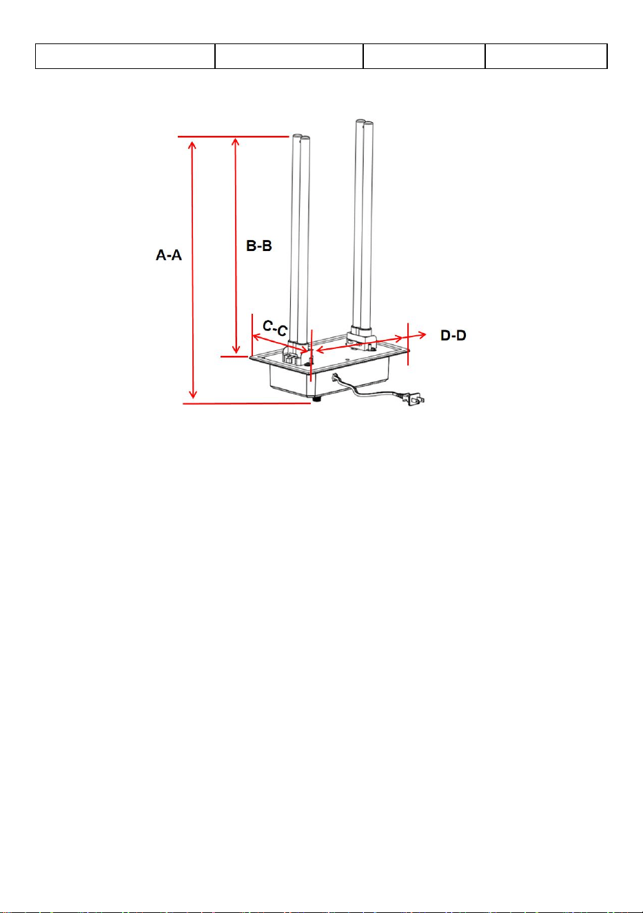
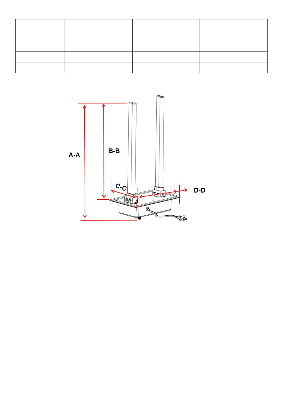
Product size
Model
2112-UV36
2006-UV9X2
2112-UV36X2
A-A
492mm
217mm
498mm
B-B
About 411mm
About 145mm
About 411mm
C-C
156mm
126mm
156nm
D-D
258mm
175mm
258mm
5
Note: Please note whether the interior space of the HVAC pipe can
accommodate the product.
Installation Instructions
How To Install Your UV Air Treatment System
If your heating/cooling (HVAC) system is equipped with air conditioning, it
is recommended that the UV Air Treatment System (unit) be mounted
directly above the cooling coil. The unit can prevent the growth of a high
percentage of micro-organisms such as mold, bacteria and viruses on
surfaces such as cooling coils, drain pans and duct work.
Selecting Mounting Location
1. The unit can be mounted in any orientation, but should be mounted in a
way that the indicator light can be seen.
2. Choose a location that will make changing/cleaning of the UV bulb(s)
easy.
3. Install unit on a flat surface of the duct work ABOVE the air conditioning
cooling coil (“A Coil”) if your HVAC system has air conditioning. If your

6
HVAC system does not have air conditioning, the unit should be installed
on the supply air duct if possible. The unit can be installed on a return air
duct if necessary
CAUTION: Do not install the unit in the “A coil” or under a humidifier
as damage may occur.
If you are unsure if you have chosen a correct mounting location, refer to
your HVAC system’s owners manual or call a qualified professional for
assistance.
4. Be sure to locate the unit away from any plastic or rubber components
that may be damaged by UV light. If mounting options are limited, plastic
and rubber may be covered with aluminum foil duct tape in order to protect
them from the UV light.
5.The unit has a 4.92 foot power cord that must be installed in a ground
power outlet; if there is no power outlet within the power cord, ask a
qualified professional to install a properly grounded power outlet.
Product voltage reference product nameplate.
Installation steps
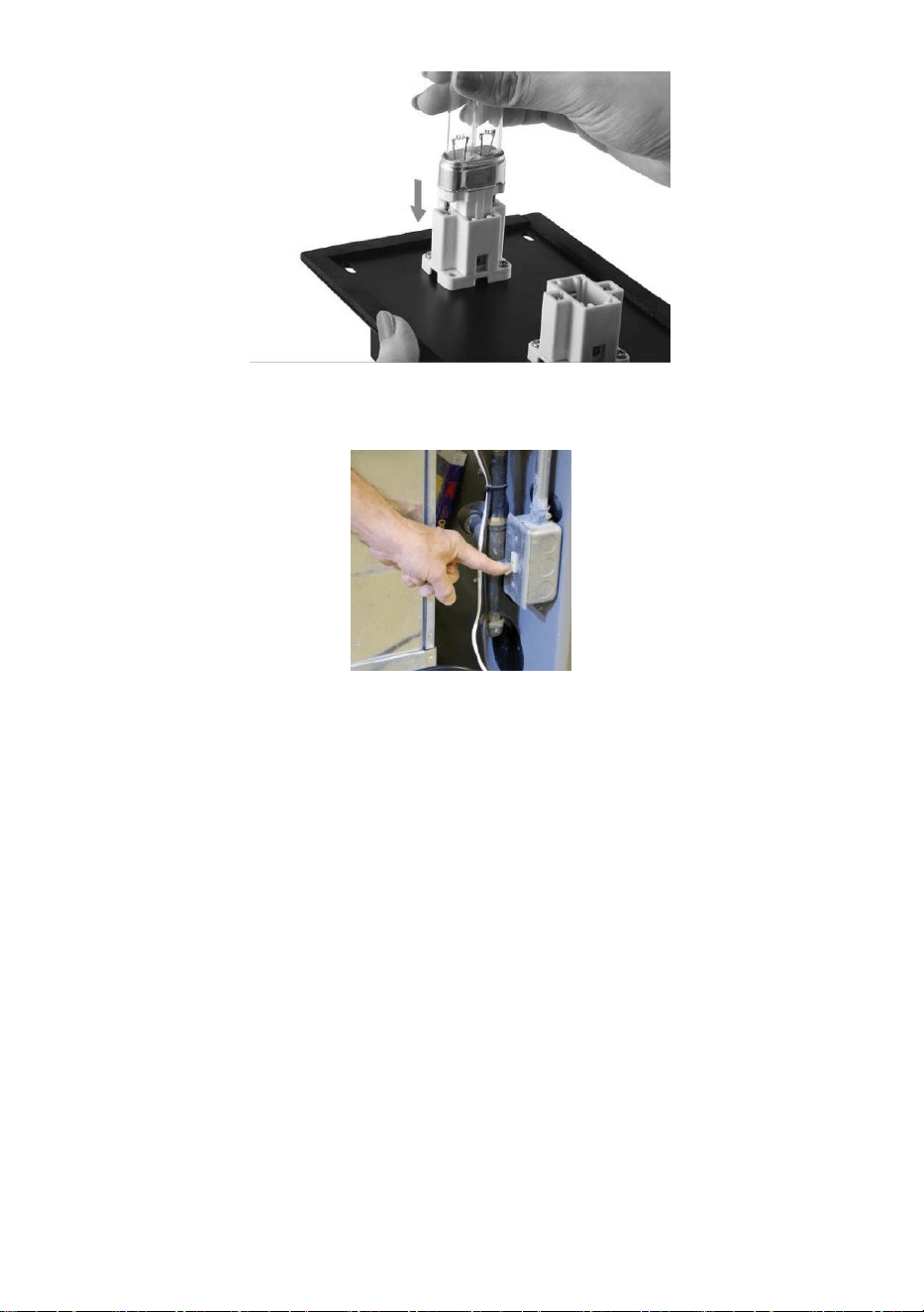
1 . Install bulbs by sliding them in from the side until bulb snaps into place.
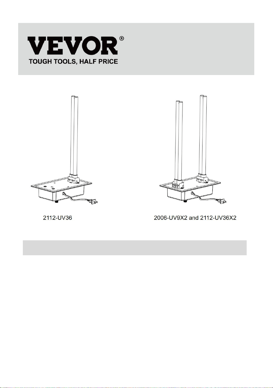
Note:The 2112-UV36 is a bulb, the 2006-UV9X2 and the 2112-UV36X2 are
two bulbs.
2 . Disconnect power to the HVAC system before installing the unit.

7
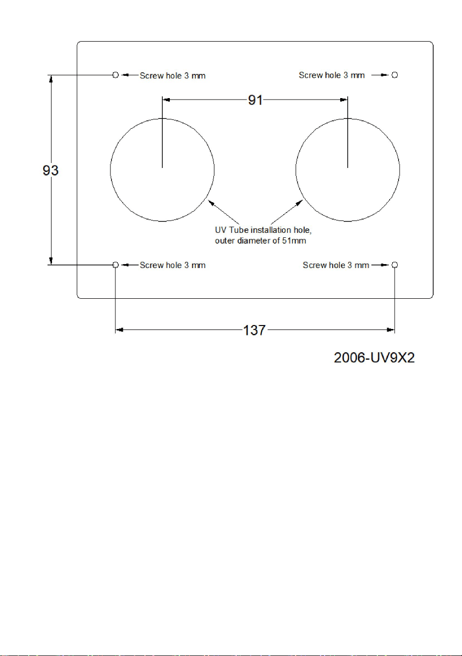
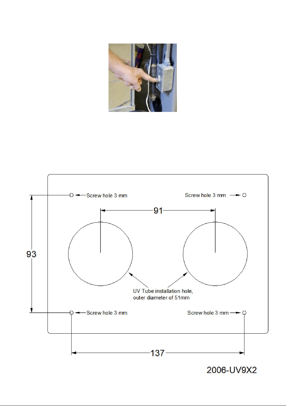
3A. Refer to the 2006-UV9X2 positioning template, first draw the position
of the installation hole with a stroke on the outer wall of the pipe, including
2 lamp pipe holes with an outer diameter of 51mm and 4 screw holes of
3mm; Processing holes using a cutting machine and 3mm drill.
8
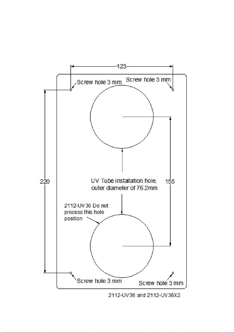
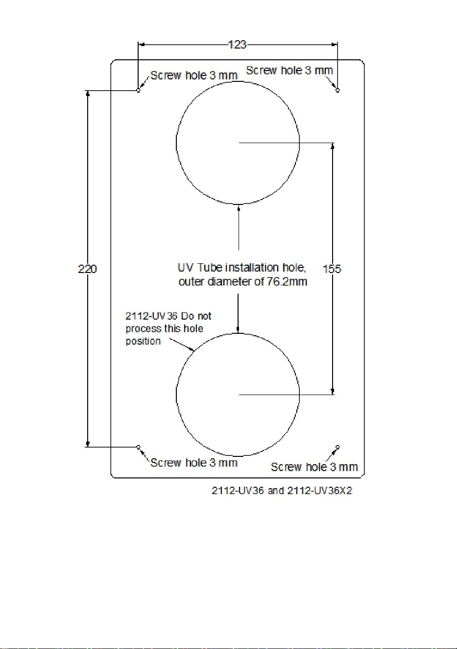
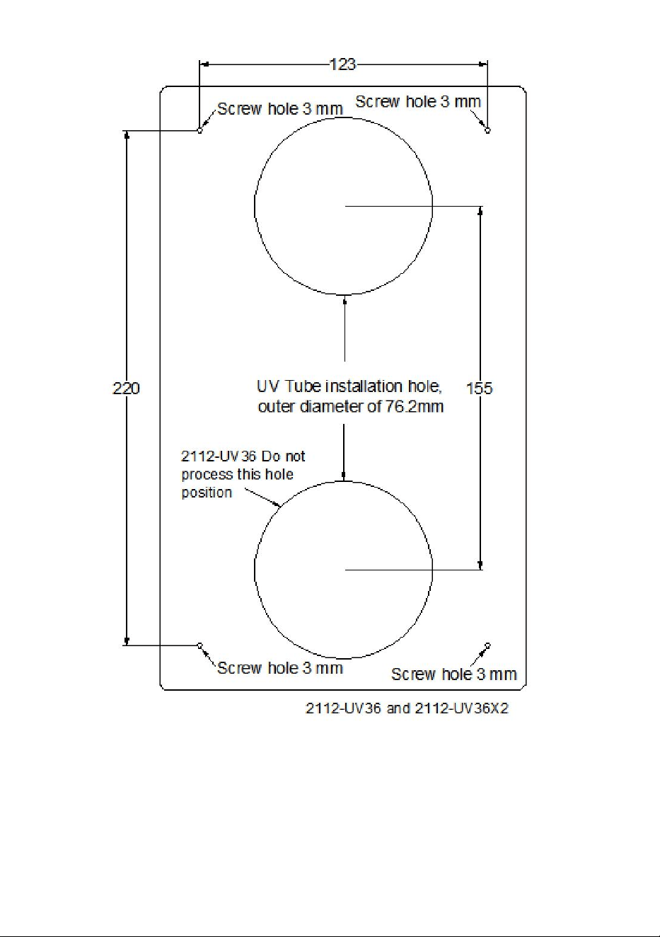
3B. Refer to the 2112-UV36X2 positioning template, first draw the position
of the installation hole with a stroke on the outer wall of the pipe, including
2 lamp pipe holes with an outer diameter of 76.2mm and 4 screw holes of
3mm; Processing holes using a cutting machine and 3mm drill.

9
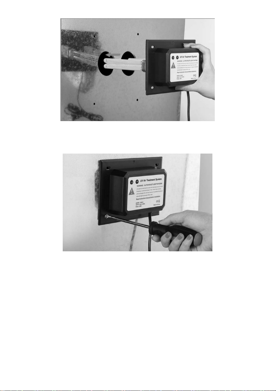
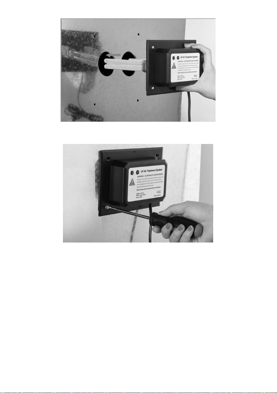
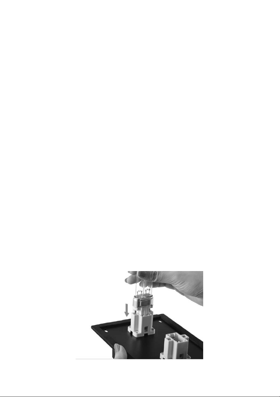
3. Insert the UV lamp into the pre-drill hole to install the UV lamp.
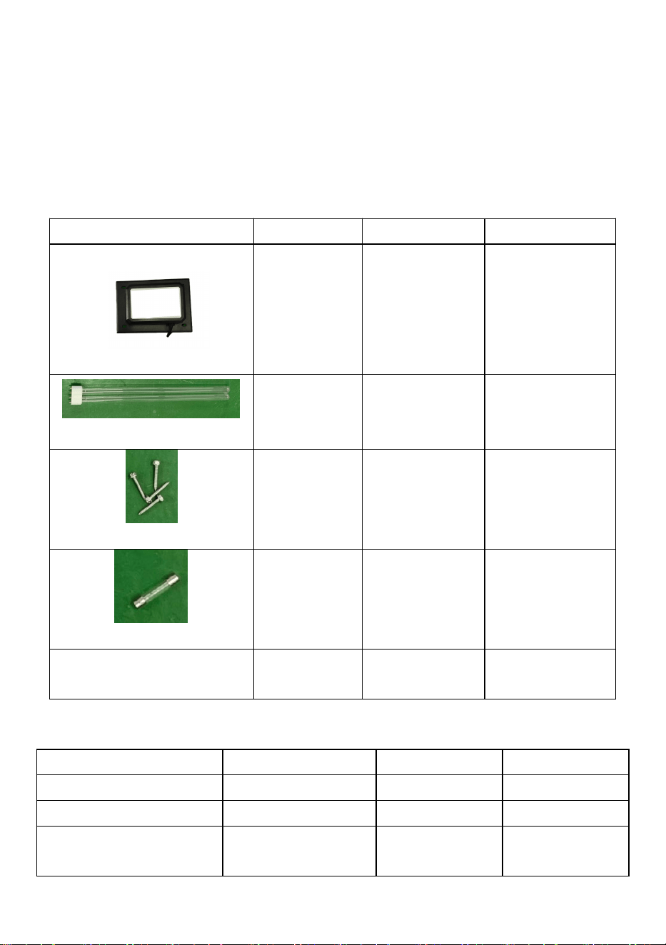
4. Install the UV lamp on the surface of the HVAC pipe with 4 screws.
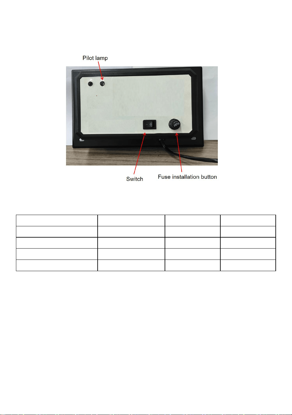
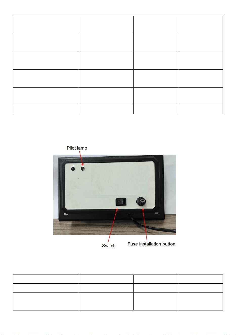
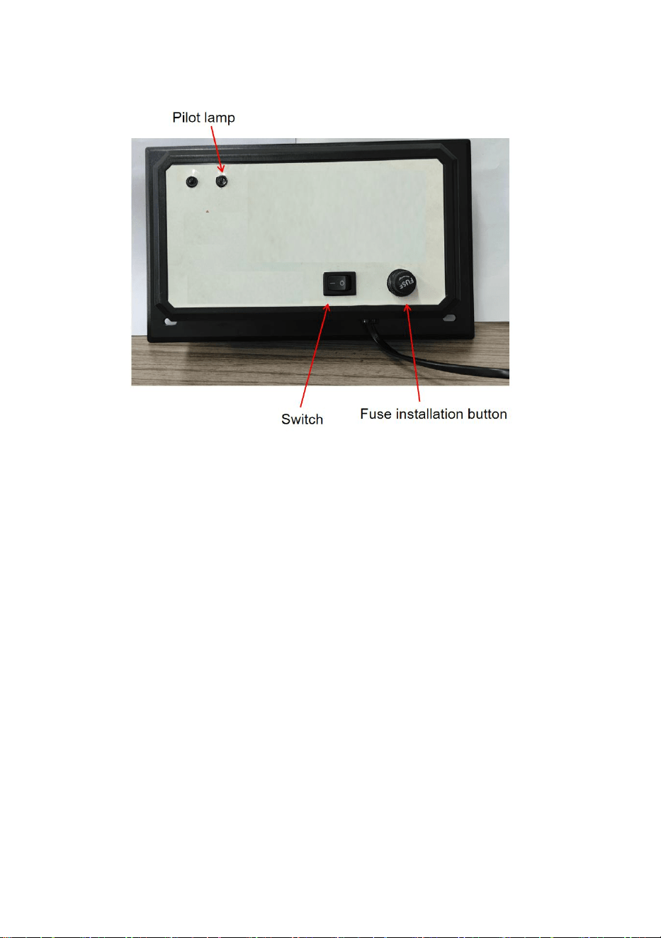
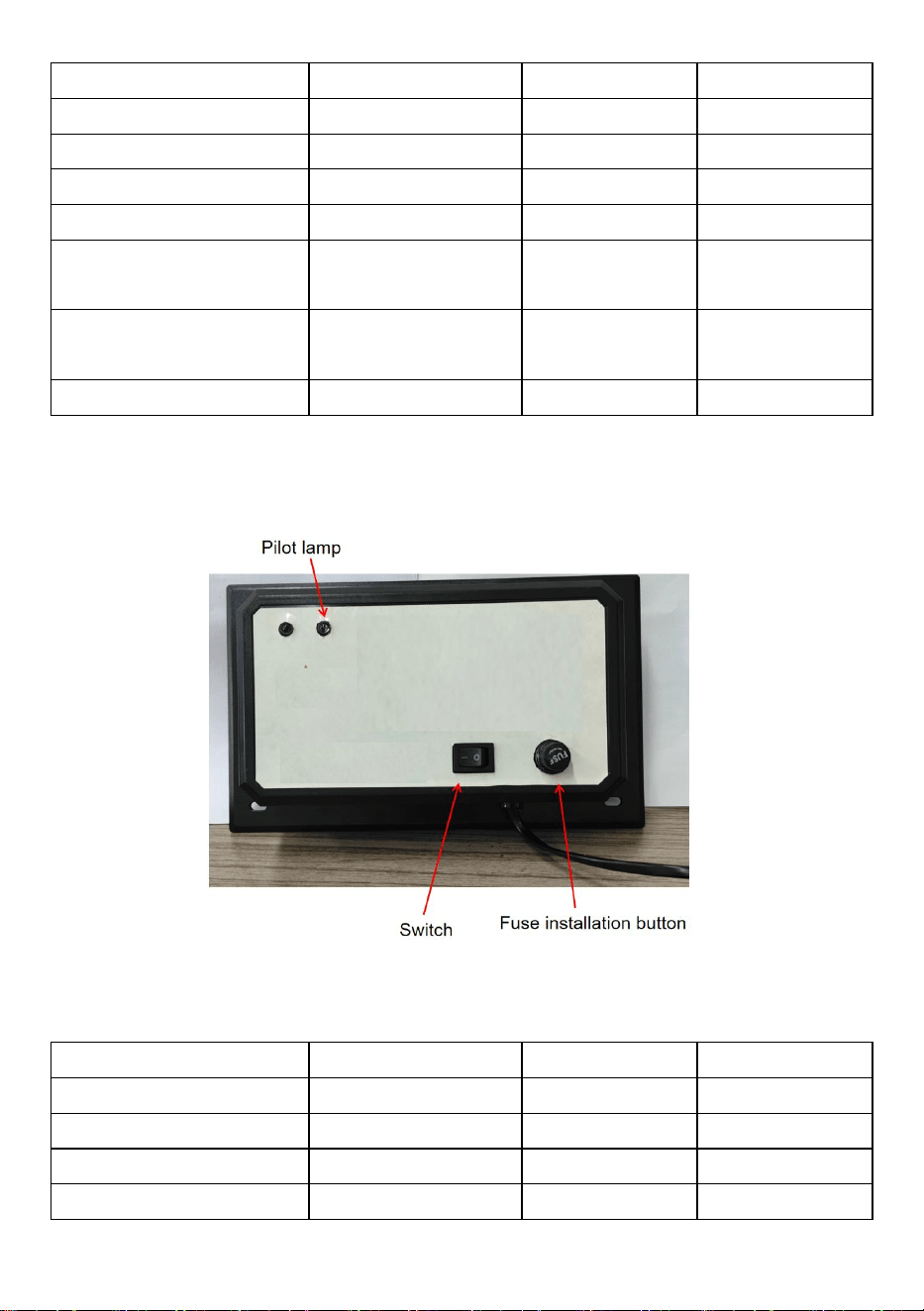
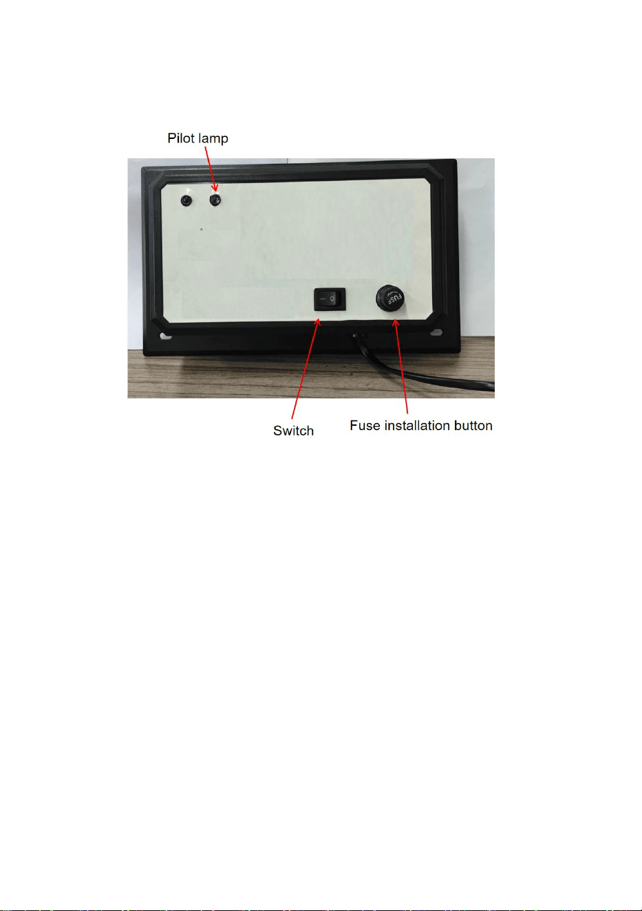
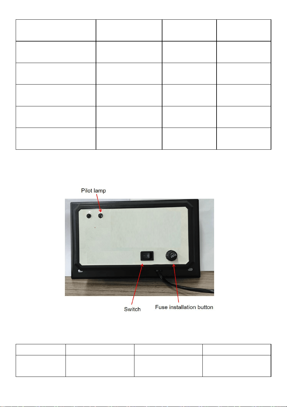
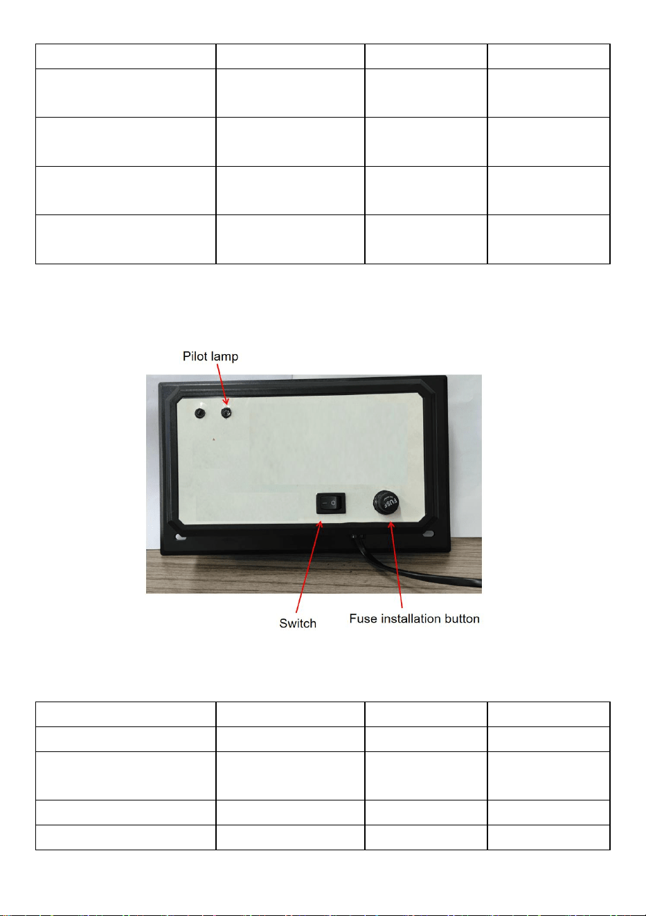
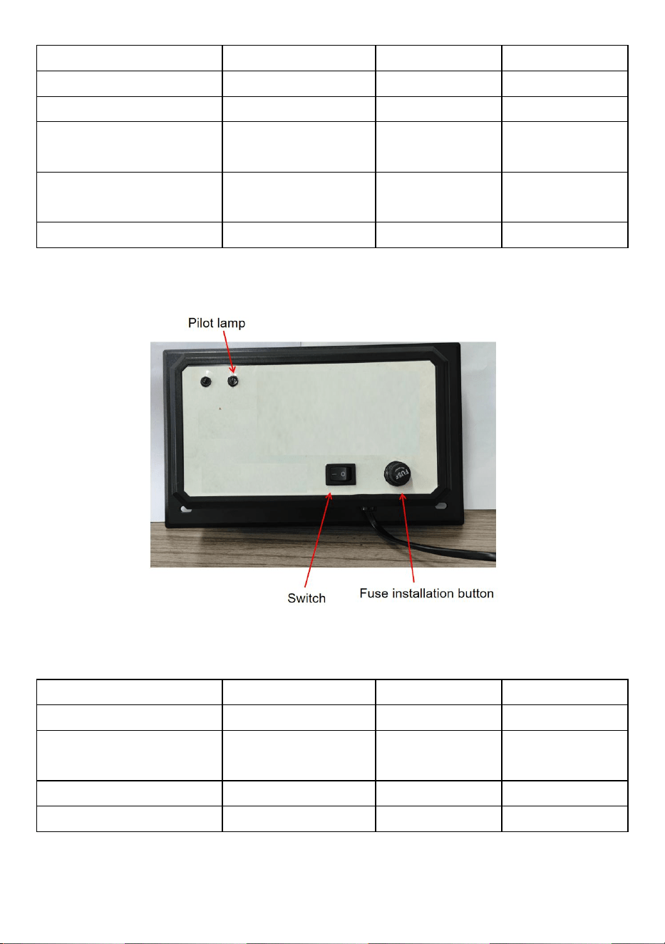
5. Connect the power plug to the AC power supply, turn on the UV Unit
switch, and light on the machine indicator light. The machine began to
work.
6. Pull out the power plug, Unscrew the fuse knob to replace the 2A fuse.
Each model of rated power supply has AC120V and AC230V. Note the
voltage and frequency information on the product nameplate.
Note:2006-UV9X2 has no switch, the access power supply starts operation;
and the fuse cannot be replaced.

10
Bulb Cleaning and Replacement
1. Disconnect the power to the HVAC system, unplug unit, and allow
UV bulb(s) to cool for at least 15 minutes before attempting to
remove the unit.
2. Remove 4 sheet metal screws and slide the unit out of the duct
work.
3a. To Clean: Hold the unit securely and wipe the UV bulb(s) with a
soft cloth dampened with glass cleaner. If you touch the glass with
your hand, be sure to wipe away any fingerprints or dirt with cloth.
Make sure the bulb is clean and dry before installing unit back into
duct.
3b. To Replace: Use of any bulb not approved for the unit will void
the warranty and could cause serious injury or damage. Hold the unit
securely and push the bulb release button to remove the UV bulb.
Install the new bulb into the unit by sliding the bulb in from the
outside until the bulb snaps into place. If you touch the bulb with your
hand, be sure to wipe away any fingerprints or dirt with a soft damp

11
cloth. Make sure the bulb(s) is/ are clean and dry before installing
the unit back into the duct.
4. Re-install the unit into the duct work and re-install the 4 sheet
metal screws. Tighten the screws evenly until unit is securely in
place. DO NOT OVERTIGHTEN SCREWS.
5. Reconnect the power to the HVAC system and plug the unit back
into a grounded power outlet.
1
Manufacturer: Shanghaimuxinmuyeyouxiangongsi
Address: Shuangchenglu 803nong11hao1602A-1609shi, baoshanqu,
shanghai 200000 CN.
Imported to AUS: SIHAO PTY LTD. 1 ROKEVA STREETEASTWOOD
NSW 2122 Australia
Imported to USA: Sanven Technology Ltd. Suite 250, 9166 Anaheim
Place, Rancho Cucamonga, CA 91730
REP
UK
YH CONSULTING LIMITED. C/O YH Consulting
Limited Office 147, Centurion House, London
Road, Staines-upon-Thames, Surrey, TW18 4AX
REP
EC
E-CrossStu GmbH
Mainzer Landstr.69,
60329 Frankfurt am Main.

2

4
Technique Certificat d'assistance et de garantie électronique
www.vevor.com/support
PURIFICATEUR D'AIR POUR SYSTÈME
CVC
MODÈLE : 2112-UV36/ 2006-UV9X2/2112-UV36X2
Nous continuons à nous engager à vous fournir des outils à des prix compétitifs.
« Économisez la moitié », « Moitié prix » ou toute autre expression similaire utilisée par
nous uniquement
représente une estimation des économies dont vous pourriez bénéficier en achetant
certains outils
avec nous par rapport aux grandes marques et ne signifie pas nécessairement couverture
toutes les catégories d'outils que nous proposons. Nous vous rappelons de bien vouloir
vérifier soigneusement

5
lorsque vous passez une commande chez nous si vous êtes réellement Économie
Moitié par rapport aux plus grandes marques.


1
Modèle : 2112-UV36/2006-UV9X2/2112-UV36X2
BESOIN D'AIDE? CONTACTEZ-NOUS!
Vous avez des questions sur les produits ? Vous avez besoin d'une
assistance technique ? N'hésitez pas à nous contacter :
Assistance technique et certificat de garantie électronique
www.vevor.com/support
Il s'agit de la notice d'utilisation d'origine. Veuillez lire attentivement toutes
les instructions du manuel avant de l'utiliser. VEVOR se réserve le droit
d'interpréter clairement notre manuel d'utilisation. L'apparence du produit
dépend du produit que vous avez reçu. Veuillez nous excuser, nous ne
vous informerons plus en cas de mise à jour technologique ou logicielle
HVAC AIR PURIFIER

2
de notre produit.
CONSIGNES DE SÉCURITÉ
1. Veuillez lire et comprendre attentivement ce manuel avant d'utiliser
l'appareil. Purificateur d'air CVC .
2. L'installation doit être effectuée par un adulte et les enfants ne doivent
pas l'utiliser sans surveillance.
3. Les rayons UV sont nocifs pour la peau et les yeux exposés, provoquant
une cécité temporaire ou permanente. Ne regardez jamais directement la
lumière UV .
4. Débranchez l'alimentation avant d'installer ou de remplacer l'ampoule
UV, sinon cela pourrait provoquer un choc électrique et la mort.
5.Veuillez porter des gants et installer le Purificateur d'air CVC pour éviter
les coupures lors de l'installation.
6. Attention au transport : Pendant le transport, le colis doit être droit,
manipulé avec précaution, éviter les chocs violents, les vibrations et les
extrusions.
7. Ne modifiez en aucun cas l'appareil. Toute modification pourrait
endommager l'appareil ou le rendre dangereux pour autrui.
8.Réparation ou l'entretien ne doit être effectué que par une personne
qualifiée.
9. Seule la tension nominale spécifiée dans ce manuel peut être utilisée.
10. N'utilisez pas ce produit dans la cuisine, où les vapeurs huileuses
peuvent réduire la durée de vie des lampes.
11. N'utilisez pas ce produit dans une zone contenant des gaz acides,
alcalins ou autres gaz organiques susceptibles de provoquer un incendie .
12. N'utilisez pas ce produit dans des endroits inflammables et explosifs,
sinon cela pourrait provoquer un incendie.
13. Le produit ne peut être démonté qu'après avoir été fermé pendant 15
minutes.
14. Le tube de la lampe contient du mercure et doit être manipulé
correctement.
15. Ne nettoyez pas les lampes cassées avec un aspirateur.
16. Le produit n'est pas étanche, le produit ne peut pas être installé dans

3
un humidificateur ou un autre environnement humide .
Liste des pièces du kit
Modèle
2112-UV36
2006-UV9X2
2112-UV36X2
Unité UV
1 pièce
1 pièce
1 pièce
Ampoule de lampe UV
2 pièces
4 pièces
4 pièces
vis
4 pièces
4 pièces
4 pièces
Gardez le fusible 2A
1 pièce
/
1 pièce
Modèle de positionnement
1 pièce
1 pièce
1 pièce
LISTE DES PARAMÈTRES
Modèle
2112-UV36
2006-UV9X2
2112-UV36X2
Pouvoir
36W
18W
72
Longueur du tube
lumineux
411 mm
145 mm
411 mm
Longueur d'onde de la
lumière
254 nm
254 nm
254 nm
4
Durée de vie des
UV
13000 heures
13000 heures
13000 heures
Tube de lampe
d'assemblage
1 pièce
2 pièces
2 pièces
Tube de lampe de
secours
1 pièce
2 pièces
2 pièces
Entrée standard
américaine
CA 120 V 60 Hz
CA 120 V 60
Hz
CA 120 V 60
Hz
Version européenne
Entrée
CA 230 V 50 Hz
CA 230 V 50
Hz
CA 230 V 50
Hz
Surface efficace
1500 pi²
600 pi²
2400 pi²
Remarque : chaque modèle d'alimentation électrique nominale est doté de
tensions CA de 120 V et CA de 230 V. Veuillez noter les informations de
tension et de fréquence sur la plaque signalétique du produit.
Taille du produit
Modèle
2112-UV36
2006-UV9X2
2112-UV36X2
AA
492 mm
217 mm
498 mm
BB
Environ 411 mm
Environ 145
mm
Environ 411
mm
5
CC
156 mm
126 mm
156 nm
DD
258 mm
175 mm
258 mm
Note: Veuillez noter si l
’
espace intérieur du tuyau CVC peut accueillir le
produit.
Instructions d'installation
Comment installer votre système de traitement d'air UV
Si votre système de chauffage/refroidissement (CVC) est équipé d'air
conditionnement, il est recommandé que les UV Le système de traitement
d'air (unité) peut être monté directement au-dessus du serpentin de
refroidissement. L'unité peut empêcher la croissance d’un pourcentage
élevé de micro-organismes tels que les moisissures, les bactéries et les
virus sur des surfaces telles que les serpentins de refroidissement, les
bacs de récupération et les conduits.
Sélection de l'emplacement de montage
1. L'unité peut être montée dans n'importe quelle orientation, mais doit être

6
montée de manière à ce que le voyant lumineux soit visible.
2. Choisissez un emplacement qui facilitera le changement/nettoyage des
ampoules UV.
3. Installez l'unité sur une surface plane du conduit AU-DESSUS du
climatiseur serpentin de refroidissement (« serpentin A ») si votre système
CVC système est équipé de la climatisation. Si votre système CVC n'est
pas équipé de la climatisation, l'unité doit être installée sur le conduit d'air
d'alimentation si possible. L'appareil peut être installé sur un conduit d'air
de retour si nécessaire
ATTENTION : N’installez pas l’appareil dans la « bobine A » ou sous
un humidificateur car des dommages pourraient survenir.
Si vous n'êtes pas sûr d'avoir choisi un emplacement de montage correct,
reportez-vous au manuel du propriétaire de votre système CVC ou appelez
un professionnel qualifié pour obtenir de l'aide.
4. Assurez-vous de placer l'appareil à l'écart de tout composant en
plastique ou en caoutchouc qui pourrait être endommagé par les rayons
UV. Si les possibilités de montage sont limitées, le plastique et le
caoutchouc peuvent être recouverts de ruban adhésif en aluminium afin de
les protéger des rayons UV.
5. L'appareil est doté d'un cordon d'alimentation de 4,92 pieds qui doit être
installé dans une prise de courant avec mise à la terre. S'il n'y a pas de
prise de courant dans le cordon d'alimentation, demandez à un
professionnel qualifié d'installer une prise de courant correctement mise à
la terre.
Référence de tension du produit plaque signalétique du produit.
Étapes d'installation
1. Installez les ampoules en les faisant glisser par le côté jusqu'à ce
qu'elles s'enclenchent .
Remarque : Le 2112-UV36 est une ampoule, le 2006-UV9X2 et le
2112-UV36X2 sont deux ampoules.

7
2. Débranchez l’ alimentation du système CVC avant d’ installer l’ unité .
3A. Reportez-vous au gabarit de positionnement 2006-UV9X2, dessinez
d'abord la position du trou d'installation avec un trait sur la paroi extérieure
du tuyau, y compris 2 trous de tuyau de lampe d'un diamètre extérieur de
51 mm et 4 trous de vis de 3 mm ; Traitement des trous à l'aide d'une
machine de découpe et d'un foret de 3 mm .

8
3B. Reportez-vous au gabarit de positionnement 2112-UV36X2 , dessinez
d'abord la position du trou d'installation avec un trait sur la paroi extérieure
du tuyau, y compris 2 trous de tuyau de lampe d'un diamètre extérieur de
76,2 mm et 4 trous de vis de 3 mm ; Traitement des trous à l'aide d'une
machine de découpe et d'un foret de 3 mm .

9
7. Insérez la lampe UV dans le trou pré-percé pour installer la lampe
UV.

10
8. Installez la lampe UV sur la surface du tuyau CVC avec 4 vis.
9. Branchez la fiche d'alimentation sur le secteur, allumez l'interrupteur de
l'unité UV et allumez le voyant lumineux de la machine. La machine a
commencé à fonctionner.
10. Débranchez la fiche d'alimentation , dévissez le bouton du fusible pour
remplacer le fusible 2A.
Chaque modèle d'alimentation électrique nominale est doté de tensions
CA 120 V et CA 230 V. Notez les informations de tension et de fréquence
sur la plaque signalétique du produit.
Remarque : le modèle 2006-UV9X2 n'a pas d'interrupteur, l'alimentation
d'accès démarre le fonctionnement ; et le fusible ne peut pas être
11
remplacé.
Nettoyage et remplacement des ampoules
1. Débranchez l'alimentation du système CVC, débranchez l'appareil
et laissez les ampoules UV refroidir pendant au moins 15 minutes
avant de tenter de retirer l'appareil.
2. Retirez les 4 vis à tôle et faites glisser l'appareil hors du conduit
travail.
3a. Pour nettoyer : maintenez fermement l'appareil et essuyez la ou
les ampoules UV avec un chiffon doux imbibé de nettoyant pour
vitres. Si vous touchez la vitre avec votre main, veillez à essuyer les
empreintes digitales ou la saleté avec un chiffon. Assurez-vous que
l'ampoule est propre et sèche avant de réinstaller l'appareil dans le
conduit.
3b. Pour remplacer : L'utilisation d'une ampoule non approuvée pour
l'appareil annulera la garantie et pourrait entraîner des blessures ou
des dommages graves. Maintenez fermement l'appareil et appuyez

12
sur le bouton de déverrouillage de l'ampoule pour retirer l'ampoule
UV. Installez la nouvelle ampoule dans l'appareil en la faisant glisser
depuis le à l'extérieur jusqu'à ce que l'ampoule s'enclenche en place.
Si vous touchez l'ampoule avec votre main, veillez à essuyer toute
trace de doigt ou saleté avec un chiffon doux et humide.
Assurez-vous que l'ampoule est propre et sèche avant de réinstaller
l'appareil dans le conduit.
4. Réinstallez l'appareil dans le conduit et réinstallez les 4 vis à tôle.
Serrez les vis uniformément jusqu'à ce que l'appareil soit bien en
place. NE PAS NE SERREZ PAS TROP LES VIS.
5. Rebranchez l’alimentation du système CVC et rebranchez
l’appareil sur une prise de courant reliée à la terre.

13

1
Fabricant : Shanghaimuxinmuyeyouxiangongsi
Adresse : Shuangchenglu 803nong11hao1602A-1609shi, baoshanqu,
Shanghai 200 000 CN.
Importé en Australie : SIHAO PTY LTD. 1 ROKEVA
STREETEASTWOOD
NSW 2122 Australie
Importé aux États-Unis : Sanven Technology Ltd. Suite 250, 9166
Anaheim
Lieu, Rancho Cucamonga, CA 91730
REP
UK
YH CONSULTING LIMITED. C/O YH Consulting
Limited Office 147, Centurion House, London
Road, Staines-upon-Thames, Surrey, TW18 4AX
REP
EC
E-CrossStu GmbH
Mainzer Landstr.69,
60329 Frankfurt am Main.

2

3

5
Technisch Support und E-Garantie-Zertifikat www.vevor.com/support
HVAC-LUFTREINIGER
MODELL: 2112-UV36/ 2006-UV9X2/2112-UV36X2
Wir sind weiterhin bestrebt, Ihnen Werkzeuge zu wettbewerbsfähigen Preisen anzubieten.
"Sparen Sie die Hälfte", "Halber Preis" oder andere ähnliche Ausdrücke, die wir nur
verwenden
stellt eine Schätzung der Einsparungen dar, die Sie durch den Kauf bestimmter Werkzeuge
erzielen können
mit uns im Vergleich zu den großen Top-Marken und bedeutet nicht unbedingt, Abdeckung
alle von uns angebotenen Werkzeugkategorien. Wir möchten Sie bitten, zu überprüfen
sorgfältig
wenn Sie bei uns eine Bestellung aufgeben, wenn Sie tatsächlich Speichern
Hälfte im Vergleich mit den Top-Großmarken.

6


1
Modell : 2112-UV36/2006-UV9X2/2112-UV36X2
Brauchen Sie Hilfe? Kontaktieren Sie uns!
Sie haben Fragen zu unseren Produkten? Sie benötigen technischen
Support? Dann kontaktieren Sie uns gerne:
Technischer Support und E-Garantie-Zertifikat
www.vevor.com/support
Dies ist die Originalanleitung. Bitte lesen Sie alle Anweisungen sorgfältig
durch, bevor Sie das Gerät in Betrieb nehmen. VEVOR behält sich eine
klare Auslegung unserer Bedienungsanleitung vor. Das Erscheinungsbild
des Produkts richtet sich nach dem Produkt, das Sie erhalten haben. Bitte
verzeihen Sie uns, dass wir Sie nicht erneut informieren, wenn es
HVAC AIR PURIFIER

2
Technologie- oder Software-Updates für unser Produkt gibt .
SICHERHEITSHINWEISE
1. Bitte lesen Sie dieses Handbuch sorgfältig durch, bevor Sie das
HVAC-Luftreiniger .
2. Die Installation sollte von einem Erwachsenen durchgeführt werden und
Kinder sollten das Gerät nicht ohne Aufsicht verwenden.
3. UV - Licht ist schädlich für Haut und Augen und kann zu
vorübergehender oder dauerhafter Erblindung führen. Schauen Sie
niemals direkt in das UV-Licht.
4. Trennen Sie die Stromversorgung, bevor Sie die UV-Lampe installieren
oder austauschen. Andernfalls kann es zu einem Stromschlag und zum
Tod kommen.
5.Bitte tragen Sie Handschuhe und installieren Sie die HVAC-Luftreiniger,
um Schnitte während der Installation zu vermeiden.
6. Achtung beim Transport: Während des Transports sollte die Verpackung
aufrecht stehen, vorsichtig behandelt werden und starke Stöße,
Vibrationen und Quetschungen vermieden werden.
7. Verändern Sie das Gerät in keiner Weise. Jede Veränderung könnte das
Gerät beschädigen oder es für andere gefährlich machen.
8.Reparatur oder Wartungsarbeiten dürfen nur von qualifiziertem
Fachpersonal durchgeführt werden.
9. Es darf nur die in diesem Handbuch angegebene Nennspannung
verwendet werden.
10. Verwenden Sie dieses Produkt nicht in der Küche, da die öligen
Dämpfe die Lebensdauer der Lampen verkürzen können.
11. Verwenden Sie dieses Produkt nicht in der Umgebung von sauren,
alkalischen oder anderen organischen Gasen, da dies zu einem Brand
führen kann .
12. Verwenden Sie dieses Produkt nicht an brennbaren und explosiven
Orten, da es sonst zu einem Brand kommt.
13. Das Produkt kann erst zerlegt werden, nachdem das Produkt 15
Minuten lang geschlossen war .
14.Die Lampenröhre enthält Quecksilber und muss ordnungsgemäß
3
gehandhabt werden.
15. Reinigen Sie kaputte Lampen nicht mit dem Staubsauger.
16. Das Produkt ist nicht wasserdicht und kann nicht in einem
Luftbefeuchter oder einer anderen feuchten Umgebung installiert werden .
Liste der Bausatzteile
Modell
2112-UV36
2006-UV9X2
2112-UV36X2
UV-Einheit
1 Stück
1 Stück
1 Stück
UV-Lampe
2 Stück
4 Stück
4 Stück
schrauben
4 Stück
4 Stück
4 Stück
Schonen Sie die
2A-Sicherung
1 Stück
/
1 Stück
Positionierungsschablone
1 Stück
1 Stück
1 Stück
PARAMETERLISTE
Modell
2112-UV36
2006-UV9X2
2112-UV36X2
Leistung
36W
18W
72
4
Länge der Lichtröhre
411 mm
145 mm
411 mm
Lichtwellenlänge
254 nm
254 nm
254 nm
UV-Lebensdauer
13000 Stunden
13000 Stunden
13000 Stunden
Montage Lampenrohr
1 Stück
2 Stück
2 Stück
Standby-Lampenröhre
1 Stück
2 Stück
2 Stück
Amerikanischer
Standardeingang
Wechselstrom 120
V , 60 Hz
Wechselstrom
120 V , 60 Hz
Wechselstrom
120 V , 60 Hz
Europäische Version
Eingang
AC230 V 50Hz
AC230 V 50Hz
AC230 V 50Hz
Effektive Fläche
1500 m²
55 m²
229 m²
Hinweis: Jedes Modell hat eine Nennstromversorgung von 120 V und 230
V AC. Beachten Sie die Angaben zu Spannung und Frequenz auf dem
Typenschild des Produkts.
Produktgröße
Modell
2112-UV36
2006-UV9X2
2112-UV36X2
AA
492 mm
217 mm
498 mm
BB
Etwa 411mm
Etwa 145mm
Etwa 411mm
CC
156 mm
126 mm
156 nm
DD
258 mm
175 mm
258 mm
5
Notiz: Bitte beachten Sie, ob der Innenraum des HVAC-Rohrs für das
Produkt geeignet ist.
Installationsanleitung
So installieren Sie Ihr UV-Luftaufbereitungssystem
Wenn Ihr Heizungs-/Kühlsystem (HVAC) mit Luft ausgestattet ist
Konditionierung, wird empfohlen, die UV Luftaufbereitungssystem (Gerät)
direkt über der Kühlschlange montiert werden. Das Gerät kann verhindern
das Wachstum eines hohen Prozentsatzes an Mikroorganismen wie
Schimmel, Bakterien und Viren auf Oberflächen wie Kühlschlangen,
Ablaufwannen und Rohrleitungen.
Montageort auswählen
1. Das Gerät kann in jeder beliebigen Ausrichtung montiert werden, sollte
jedoch so montiert werden, dass die Kontrollleuchte sichtbar ist.
2. Wählen Sie einen Standort, an dem sich die UV-Lampe(n) leicht
austauschen bzw. reinigen lassen.

6
3. Installieren Sie das Gerät auf einer ebenen Fläche des Kanalsystems
ÜBER der Klimaanlage Kühlschlange („A-Spule“), wenn Ihre HVAC
System hat eine Klimaanlage. Wenn Ihr HLK-System keine Klimaanlage
hat, sollte das Gerät installiert werden wenn möglich am Zuluftkanal. Das
Gerät kann bei Bedarf auch am Rückluftkanal installiert werden
ACHTUNG: Installieren Sie das Gerät nicht in der „A-Spule“ oder
unter einem Luftbefeuchter, da es zu Schäden kommen kann.
Wenn Sie sich nicht sicher sind, ob Sie den richtigen Montageort gewählt
haben, schlagen Sie im Benutzerhandbuch Ihres HLK-Systems nach oder
wenden Sie sich zur Unterstützung an einen qualifizierten Fachmann.
4. Stellen Sie sicher, dass das Gerät nicht in der Nähe von Kunststoff- oder
Gummiteilen angebracht ist, die durch UV-Licht beschädigt werden
könnten. Wenn die Montagemöglichkeiten begrenzt sind, können
Kunststoff und Gummi mit Aluminiumfolienklebeband abgedeckt werden,
um sie vor UV-Licht zu schützen.
5. Das Gerät verfügt über ein 1,5 m langes Netzkabel, das an eine
geerdete Steckdose angeschlossen werden muss. Wenn sich im
Netzkabel keine Steckdose befindet, bitten Sie einen qualifizierten
Fachmann mit der Installation einer ordnungsgemäß geerdeten
Steckdose.
Produktspannungsreferenz, Produkttypenschild.
Installationsschritte
1. Installieren Sie die Glühbirnen, indem Sie sie von der Seite
einschieben , bis die Glühbirne einrastet .
Hinweis: 2112-UV36 ist eine Glühbirne, 2006-UV9X2 und 2112-UV36X2
sind zwei Glühbirnen.

7
2. Trennen Sie das HLK- System von der Stromversorgung , bevor Sie das
Gerät neu installieren .
3A. Beziehen Sie sich auf die Positionierungsvorlage 2006-UV9X2.
Zeichnen Sie zuerst die Position des Installationslochs mit einem Strich auf
die Außenwand des Rohrs, einschließlich 2 Lampenrohrlöchern mit einem
Außendurchmesser von 51 mm und 4 Schraubenlöchern von 3 mm.
Bearbeiten Sie die Löcher mit einer Schneidemaschine und einem
3-mm-Bohrer .

8
3B. Beziehen Sie sich auf die Positionierungsvorlage 2112-UV36X2 .
Zeichnen Sie zuerst die Position des Installationslochs mit einem Strich auf
die Außenwand des Rohrs, einschließlich 2 Lampenrohrlöchern mit einem
Außendurchmesser von 76,2 mm und 4 Schraubenlöchern von 3 mm.
Bearbeiten Sie die Löcher mit einer Schneidemaschine und einem
3-mm-Bohrer .

9
11. Setzen Sie die UV-Lampe in das vorgebohrte Loch ein, um die
UV-Lampe zu installieren.
10
12. Installieren Sie die UV-Lampe mit 4 Schrauben auf der Oberfläche des
HVAC-Rohrs.
13. Schließen Sie den Netzstecker an die Wechselstromversorgung an,
schalten Sie den Schalter der UV-Einheit ein und lassen Sie die
Kontrollleuchte der Maschine einschalten. Die Maschine beginnt zu
arbeiten.
14. Ziehen Sie den Netzstecker. Schrauben Sie den Sicherungsknopf ab ,
um die 2A-Sicherung auszutauschen.
Jedes Modell verfügt über eine Nennstromversorgung von 120 V AC und
230 V AC. Beachten Sie die Angaben zu Spannung und Frequenz auf dem
Typenschild des Produkts.
11
Hinweis: 2006-UV9X2 hat keinen Schalter, das Zugangsnetzteil startet den
Betrieb und die Sicherung kann nicht ausgetauscht werden.
Reinigung und Austausch der Glühbirne
1. Trennen Sie die Stromversorgung des HLK-Systems, ziehen Sie
den Stecker aus der Steckdose und lassen Sie die UV-Lampe(n)
mindestens 15 Minuten abkühlen, bevor Sie versuchen, Entfernen
Sie die Einheit.
2. Entfernen Sie die 4 Blechschrauben und schieben Sie das Gerät
aus dem Kanal arbeiten.
3a. Reinigen: Halten Sie das Gerät fest und wischen Sie die
UV-Lampe(n) mit einem weichen, mit Glasreiniger angefeuchteten
Tuch ab. Wenn Sie das Glas mit der Hand berühren, wischen Sie
Fingerabdrücke und Schmutz unbedingt mit einem Tuch ab. Stellen
Sie sicher, dass die Lampe sauber und trocken ist, bevor Sie das
Gerät wieder in den Kanal einbauen.

12
3b. Auswechseln: Die Verwendung einer nicht für das Gerät
zugelassenen Lampe macht die Garantie ungültig und kann zu
schweren Verletzungen oder Schäden führen. Halten Sie das Gerät
fest und drücken Sie den Lampenentriegelungsknopf, um die
UV-Lampe zu entfernen. Setzen Sie die neue Lampe in das Gerät
ein, indem Sie die Lampe von der außen, bis die Glühbirne einrastet.
Wenn Sie die Glühbirne mit der Hand berühren, wischen Sie
Fingerabdrücke oder Schmutz unbedingt mit einem weichen,
feuchten Tuch ab. Stellen Sie sicher, dass die Glühbirne(n) sauber
und trocken sind , bevor Sie das Gerät wieder in den Kanal
einsetzen.
4. Installieren Sie das Gerät wieder im Kanalsystem und bringen Sie
die 4 Blechschrauben wieder an. Ziehen Sie die Schrauben
gleichmäßig an, bis das Gerät sicher sitzt. NICHT SCHRAUBEN
NICHT ZU ÜBERFEST ZIEHEN.
5. Schließen Sie die Stromversorgung des HLK-Systems wieder an
und stecken Sie das Gerät wieder in eine geerdete Steckdose.

13

1
Hersteller: Shanghaimuxinmuyeyouxiangongsi
Adresse: Shuangchenglu 803nong11hao1602A-1609shi, baoshanqu,
Shanghai, 200.000 CN.
Nach AUS importiert: SIHAO PTY LTD. 1 ROKEVA
STREETEASTWOOD
NSW 2122 Australien
Importiert in die USA: Sanven Technology Ltd. Suite 250, 9166 Anaheim
Ort, Rancho Cucamonga, CA 91730
REP
UK
YH CONSULTING LIMITED. C/O YH Consulting
Limited Office 147, Centurion House, London
Road, Staines-upon-Thames, Surrey, TW18 4AX
REP
EC
E-CrossStu GmbH
Mainzer Landstr.69,
60329 Frankfurt am Main.

2
3
Technisch Support und E-Garantie-Zertifikat


5
Tecnico Supporto e certificato di garanzia elettronica www.vevor.com/support
PURIFICATORE D'ARIA HVAC
MODELLO: 2112-UV36/ 2006-UV9X2/2112-UV36X2
Continuiamo a impegnarci per fornirvi strumenti a prezzi competitivi.
"Risparmia la metà", "Metà prezzo" o altre espressioni simili utilizzate solo da noi
rappresenta una stima dei risparmi che potresti ottenere acquistando determinati strumenti
con noi rispetto ai principali marchi top e non significa necessariamente copertina
tutte le categorie di strumenti da noi offerti. Ti ricordiamo cortesemente di verificare
accuratamente
quando effettui un ordine con noi se sei effettivamente Risparmio
Metà rispetto ai marchi più importanti.

6


1
Modello : 2112-UV36/2006-UV9X2/2112-UV36X2
HAI BISOGNO DI AIUTO? CONTATTACI!
Hai domande sui prodotti? Hai bisogno di supporto tecnico? Non
esitare a contattarci:
Supporto tecnico e certificato di garanzia elettronica
www.vevor.com/support
Questa è l'istruzione originale, si prega di leggere attentamente tutte le
istruzioni del manuale prima di utilizzare. VEVOR si riserva una chiara
interpretazione del nostro manuale utente. L'aspetto del prodotto sarà
soggetto al prodotto ricevuto. Vi preghiamo di perdonarci se non vi
informeremo di nuovo se ci sono aggiornamenti tecnologici o software sul
HVAC AIR PURIFIER

2
nostro prodotto.
ISTRUZIONI DI SICUREZZA
1. Si prega di leggere e comprendere attentamente il presente manuale
prima di utilizzare il Purificatore d'aria HVAC .
2. L'installazione deve essere eseguita da un adulto e i bambini non
devono utilizzarla senza supervisione.
3. Le luci UV sono dannose per la pelle e gli occhi esposti, causando cecità
temporanea o permanente. Non guardare mai direttamente la luce UV .
4. Scollegare l'alimentazione prima di installare o sostituire la lampadina
UV, altrimenti si potrebbero verificare scosse elettriche e morte.
5. Indossare guanti e installare il Purificatore d'aria HVAC per evitare tagli
durante l'installazione.
6. Attenzione al trasporto: durante il trasporto, il pacco deve essere
mantenuto in posizione verticale, maneggiato con cura, evitando forti urti,
vibrazioni ed estrusioni.
7. Non modificare l'unità in alcun modo. Qualsiasi modifica potrebbe
danneggiare il dispositivo o renderlo pericoloso per gli altri.
8.Riparazione o la manutenzione deve essere eseguita solo da una
persona qualificata.
9. È possibile utilizzare solo la tensione nominale specificata nel presente
manuale.
10. Non utilizzare questo prodotto in cucina, dove i fumi oleosi potrebbero
ridurre la durata delle lampade.
11. Non utilizzare questo prodotto in aree acide, alcaline o con altri gas
organici dove potrebbe verificarsi un incendio .
12. Non utilizzare questo prodotto in luoghi infiammabili o esplosivi,
altrimenti potrebbe causare un incendio.
13. Il prodotto può essere smontato solo dopo essere stato chiuso per 15
minuti.
14. Il tubo della lampada contiene mercurio e deve essere maneggiato
correttamente.
15. Non pulire le lampade rotte con l'aspirapolvere.
16. Il prodotto non è impermeabile, non può essere installato in un
3
umidificatore o in altri ambienti umidi .
Elenco delle parti del kit
Modello
2112-UV36
2006-UV9X2
2112-UV36X2
Unità UV
1 pz.
1 pz.
1 pz.
Lampadina della lampada
UV
2 pezzi
4 pezzi
4 pezzi
vite
4 pezzi
4 pezzi
4 pezzi
Risparmia il fusibile da 2A
1 pz.
/
1 pz.
Modello di posizionamento
1 pz.
1 pz.
1 pz.
ELENCO DEI PARAMETRI
Modello
2112-UV36
2006-UV9X2
2112-UV36X2
Energia
36W
18W
72
Lunghezza del tubo
luminoso
411mm
145mm
411mm
Lunghezza d'onda della
254 nm
254 nm
254 nm

4
luce
Durata UV
13000 ore
13000 ore
13000 ore
Tubo lampada di
montaggio
1 pz.
2 pezzi
2 pezzi
Tubo della lampada di
standby
1 pz.
2 pezzi
2 pezzi
Input standard
americano
AC120V 60Hz
AC120V
60Hz
AC120V
60Hz
Versione europea
Ingresso
AC230V 50Hz
AC230V
50Hz
AC230V
50Hz
Area effettiva
1500 piedi quadrati
600 piedi
quadrati
2400 piedi
quadrati
Nota: ogni modello di alimentatore nominale ha AC120V e AC230V. Notare
le informazioni sulla tensione e sulla frequenza sulla targhetta del prodotto.
Dimensioni del prodotto
Modello
2112-UV36
2006-UV9X2
2112-UV36X2
AAA
492mm
217mm
498mm
BB
Circa 411mm
Circa 145mm
Circa 411mm
CC
156mm
126mm
156 nm
5
GG
258mm
175mm
258mm
Nota: Verificare se lo spazio interno del tubo HVAC può contenere il
prodotto.
Istruzioni per l'installazione
Come installare il sistema di trattamento dell'aria UV
Se il tuo sistema di riscaldamento/raffreddamento (HVAC) è dotato di aria
condizionamento, si raccomanda che i raggi UV Il sistema di trattamento
dell'aria (unità) può essere montato direttamente sopra la serpentina di
raffreddamento. L'unità può prevenire la crescita di un'elevata percentuale
di microrganismi quali muffe, batteri e virus su superfici quali serpentine di
raffreddamento, vaschette di raccolta e condotti.
Selezione della posizione di montaggio
1. L'unità può essere montata in qualsiasi orientamento, ma deve essere
montata in modo che la spia luminosa sia visibile.
2. Scegliere una posizione che renda semplice la sostituzione/pulizia delle

6
lampadine UV.
3. Installare l'unità su una superficie piana della condotta SOPRA l'aria
condizionata serpentina di raffreddamento ("serpentina A") se il tuo HVAC
il sistema è dotato di aria condizionata. Se il tuo sistema HVAC non è
dotato di aria condizionata, l'unità dovrebbe essere installata sul condotto
dell'aria di mandata, se possibile. L'unità può essere installata su un
condotto dell'aria di ritorno, se necessario
ATTENZIONE: non installare l'unità nella "serpentina A" o sotto un
umidificatore poiché potrebbe danneggiarsi.
Se non sei sicuro di aver scelto la posizione di montaggio corretta,
consulta il manuale del proprietario del tuo sistema HVAC o chiama un
professionista qualificato per ricevere assistenza.
4. Assicurarsi di posizionare l'unità lontano da componenti in plastica o
gomma che potrebbero essere danneggiati dalla luce UV. Se le opzioni di
montaggio sono limitate, la plastica e la gomma possono essere coperte
con nastro adesivo in alluminio per proteggerle dalla luce UV.
5. L'unità è dotata di un cavo di alimentazione da 1,5 metri che deve
essere installato in una presa di corrente con messa a terra; se il cavo di
alimentazione non è dotato di una presa di corrente, chiedere a un
professionista qualificato di installare una presa di corrente con messa a
terra adeguata.
Targhetta del prodotto con riferimento alla tensione del prodotto.
Fasi di installazione
1. Installare le lampadine facendole scorrere lateralmente finché non
scattano in posizione .
Nota: la 2112-UV36 è una lampadina, la 2006-UV9X2 e la 2112-UV36X2
sono due lampadine.

7
2. Scollegare l' alimentazione al sistema HVAC prima di installare l'
unità .
3A. Fare riferimento al modello di posizionamento 2006-UV9X2, disegnare
prima la posizione del foro di installazione con un tratto sulla parete
esterna del tubo, inclusi 2 fori per il tubo della lampada con un diametro
esterno di 51 mm e 4 fori per viti da 3 mm; Lavorare i fori utilizzando una
macchina da taglio e un trapano da 3 mm .

8
3B. Fare riferimento al modello di posizionamento 2112-UV36X2 ,
disegnare prima la posizione del foro di installazione con un tratto sulla
parete esterna del tubo, inclusi 2 fori per il tubo della lampada con un
diametro esterno di 76,2 mm e 4 fori per viti da 3 mm; Lavorare i fori
utilizzando una macchina da taglio e un trapano da 3 mm .
9
15. Inserire la lampada UV nel foro predisposto per installarla.
10
16. Installare la lampada UV sulla superficie del tubo HVAC con 4 viti.
17. Collegare la spina di alimentazione all'alimentazione CA, accendere
l'interruttore dell'unità UV e accendere la spia luminosa della macchina. La
macchina ha iniziato a funzionare.
18. Estrarre la spina di alimentazione , svitare la manopola del fusibile per
sostituire il fusibile da 2A.
Ogni modello di alimentatore nominale ha AC120V e AC230V. Notare le
informazioni sulla tensione e sulla frequenza sulla targhetta del prodotto.
Nota: il modello 2006-UV9X2 non ha interruttore, l'alimentatore di accesso
inizia a funzionare e il fusibile non può essere sostituito.

11
Pulizia e sostituzione della lampadina
1. Scollegare l'alimentazione al sistema HVAC, scollegare l'unità e
lasciare raffreddare la/le lampadina/e UV per almeno 15 minuti
prima di tentare di rimuovere l'unità.
2. Rimuovere le 4 viti per lamiera e far scorrere l'unità fuori dal
condotto lavoro.
3a. Per pulire: tenere saldamente l'unità e pulire la/le lampadina/e
UV con un panno morbido inumidito con detergente per vetri. Se si
tocca il vetro con la mano, assicurarsi di pulire eventuali impronte
digitali o sporcizia con un panno. Assicurarsi che la lampadina sia
pulita e asciutta prima di reinstallare l'unità nel condotto.
3b. Per sostituire: l'uso di una lampadina non approvata per l'unità
invaliderà la garanzia e potrebbe causare gravi lesioni o danni.
Tenere saldamente l'unità e premere il pulsante di rilascio della
lampadina per rimuovere la lampadina UV. Installare la nuova
lampadina nell'unità facendola scorrere dall' all'esterno finché la
lampadina non scatta in posizione. Se tocchi la lampadina con la

12
mano, assicurati di pulire eventuali impronte digitali o sporcizia con
un panno morbido umido. Assicurati che la/le lampadina/e sia / siano
pulita/e e asciutta/e prima di reinstallare l'unità nel condotto.
4. Reinstallare l'unità nella condotta e reinstallare le 4 viti per lamiera.
Serrare le viti in modo uniforme finché l'unità non è saldamente in
posizione. NON SERRARE ECCESSIVAMENTE LE VITI.
5. Ricollegare l'alimentazione al sistema HVAC e ricollegare l'unità a
una presa di corrente dotata di messa a terra.

13

1
Produttore: Shanghaimuxinmuyeyouxiangongsi
Indirizzo: Shuangchenglu 803nong11hao1602A-1609shi, baoshanqu,
shanghai 200000 CN.
Importato in AUS: SIHAO PTY LTD. 1 ROKEVA STREETEASTWOOD
Nuovo Galles del Sud 2122 Australia
Importato negli USA: Sanven Technology Ltd. Suite 250, 9166 Anaheim
Luogo, Rancho Cucamonga, CA 91730
REP
UK
YH CONSULTING LIMITED. C/O YH Consulting
Limited Office 147, Centurion House, London
Road, Staines-upon-Thames, Surrey, TW18 4AX
REP
EC
E-CrossStu GmbH
Mainzer Landstr.69,
60329 Frankfurt am Main.

2


4
Técnico Soporte y certificado de garantía electrónica www.vevor.com/support
PURIFICADOR DE AIRE HVAC
MODELO: 2112-UV36/ 2006-UV9X2/2112-UV36X2
Seguimos comprometidos a brindarle herramientas a precios competitivos.
"Ahorra la mitad", "mitad de precio" o cualquier otra expresión similar utilizada únicamente
por nosotros
Representa una estimación de los ahorros que podría obtener al comprar ciertas
herramientas.
con nosotros en comparación con las principales marcas líderes y no significa
necesariamente cubrir
Todas las categorías de herramientas que ofrecemos. Le recordamos que debe verificar
con cuidado
Cuando realiza un pedido con nosotros, si realmente está Ahorro
Medio en comparación con las principales marcas líderes.

5


1
Modelo : 2112-UV36/2006-UV9X2/2112-UV36X2
¿NECESITA AYUDA? ¡CONTÁCTENOS!
¿Tiene preguntas sobre el producto? ¿Necesita asistencia técnica? No
dude en ponerse en contacto con nosotros:
Soporte técnico y certificado de garantía electrónica
www.vevor.com/support
Estas son las instrucciones originales, lea atentamente todas las
instrucciones del manual antes de utilizar el producto. VEVOR se reserva
una interpretación clara de nuestro manual de usuario. La apariencia del
producto estará sujeta al producto que recibió. Perdónenos por no
informarle nuevamente si hay actualizaciones de tecnología o software
HVAC AIR PURIFIER

2
en nuestro producto.
INSTRUCCIONES DE SEGURIDAD
1. Lea y comprenda este manual detenidamente antes de utilizar el
Purificador de aire HVAC .
2. La instalación debe ser realizada por un adulto y los niños no deben
utilizarlo sin supervisión.
3. Las luces ultravioleta son dañinas para la piel y los ojos expuestos, y
pueden causar ceguera temporal o permanente. Nunca mire directamente
a la luz ultravioleta.
4. Desconecte la alimentación antes de instalar o reemplazar la bombilla
UV, de lo contrario podría provocar una descarga eléctrica y la muerte.
5. Utilice guantes e instale el Purificador de Aire HVAC para evitar cortes
durante la instalación.
6. Atención durante el transporte: durante el transporte, el paquete debe
estar en posición vertical, manipularse con cuidado, evitar impactos
fuertes, vibraciones y extrusiones.
7. No modifique la unidad de ninguna manera. Cualquier modificación
podría dañar el dispositivo o hacerlo peligroso para otras personas.
8.Reparación o el mantenimiento sólo debe ser realizado por una persona
calificada.
9.Solo se puede utilizar el voltaje nominal especificado en este manual.
10. No utilice este producto en la cocina, donde el humo aceitoso puede
acortar la vida útil de las lámparas.
11. No utilice este producto en áreas con gases ácidos, alcalinos u otros
gases orgánicos donde pueda provocar incendios .
12.No utilice este producto en lugares inflamables o explosivos, de lo
contrario podría provocar un incendio.
13. El producto solo se puede desmontar después de permanecer cerrado
durante 15 minutos.
14.El tubo de la lámpara contiene mercurio y debe manipularse
adecuadamente.
15.No limpie las lámparas rotas con una aspiradora.
16. El producto no es resistente al agua, por lo que no se puede instalar en
3
un humidificador ni en ningún otro entorno húmedo .
Lista de piezas del kit
Modelo
2112-UV36
2006-UV9X2
2112-UV36X2
Unidad UV
1 pieza
1 pieza
1 pieza
Bombilla de lámpara UV
2 piezas
4 piezas
4 piezas
tornillo
4 piezas
4 piezas
4 piezas
Ahorre el fusible 2A
1 pieza
/
1 pieza
Plantilla de
posicionamiento
1 pieza
1 pieza
1 pieza
LISTA DE PARÁMETROS
Modelo
2112-UV36
2006-UV9X2
2112-UV36X2
Fuerza
36 W
18W
72
Longitud del tubo de luz
411 mm
145 mm
411 mm
Longitud de onda de la
luz
254 nm
254 nm
254 nm
4
Vida útil de los
rayos UV
13000 horas
13000 horas
13000 horas
Tubo de lámpara de
montaje
1 pieza
2 piezas
2 piezas
Tubo de lámpara de
reserva
1 pieza
2 piezas
2 piezas
Entrada estándar
americana
CA 120 V 60 Hz
CA 120 V 60
Hz
CA 120 V 60
Hz
Versión europea
Entrada
CA 230 V 50 Hz
CA 230 V 50
Hz
CA 230 V 50
Hz
Área efectiva
1500 pies
cuadrados
600 pies
cuadrados
2400 pies
cuadrados
Nota: Cada modelo de fuente de alimentación tiene una tensión nominal
de 120 V CA y 230 V CA. Tenga en cuenta la información de voltaje y
frecuencia en la placa de identificación del producto.
Tamaño del producto
Modelo
2112-UV36
2006-UV9X2
2112-UV36X2
Automóvil
club
492 mm
217 mm
498 mm
5
británico
CAMA Y
DESAYUNO
Aproximadamente
411 mm
Aproximadamente
145 mm
Aproximadamente
411 mm
C.C.
156 mm
126 mm
156 nm
DD
258 mm
175 mm
258 mm
Nota: Tenga en cuenta si el espacio interior de la tubería HVAC puede
acomodar el producto.
Instrucciones de instalación
Cómo instalar su sistema de tratamiento de aire por UV
Si su sistema de calefacción/refrigeración (HVAC) está equipado con aire
acondicionado, se recomienda que los rayos UV El sistema de tratamiento
de aire (unidad) se puede montar directamente sobre el serpentín de
enfriamiento. La unidad puede Prevenir el crecimiento de un alto
porcentaje de microorganismos como moho, bacterias y virus en
superficies como serpentines de enfriamiento, bandejas de drenaje y
conductos.

6
Selección de la ubicación de montaje
1. La unidad se puede montar en cualquier orientación, pero debe
montarse de manera que se pueda ver la luz indicadora.
2. Elija una ubicación que facilite el cambio y la limpieza de las bombillas
UV.
3. Instale la unidad en una superficie plana del conducto ENCIMA del aire
acondicionado. Serpentín de enfriamiento (“Serpentín A”) si su sistema
HVAC El sistema tiene aire acondicionado. Si su sistema HVAC no tiene
aire acondicionado, la unidad debe instalarse Si es posible, en el conducto
de aire de suministro. La unidad se puede instalar en un conducto de aire
de retorno si es necesario.
PRECAUCIÓN: No instale la unidad en la “bobina A” o debajo de un
humidificador ya que podría dañarse.
Si no está seguro de haber elegido una ubicación de montaje correcta,
consulte el manual del propietario de su sistema HVAC o llame a un
profesional calificado para obtener ayuda.
4. Asegúrese de colocar la unidad lejos de cualquier componente de
plástico o goma que pueda dañarse con la luz ultravioleta. Si las opciones
de montaje son limitadas, se pueden cubrir el plástico y la goma con cinta
adhesiva de papel de aluminio para protegerlos de la luz ultravioleta.
5. La unidad tiene un cable de alimentación de 4,92 pies que debe
instalarse en una toma de corriente con conexión a tierra; si no hay una
toma de corriente dentro del cable de alimentación, solicite a un
profesional calificado que instale una toma de corriente con conexión a
tierra adecuada.
Placa de identificación del producto con referencia de voltaje del producto.
Pasos de instalación
1. Instale las bombillas deslizándolas desde el costado hasta que encajen
en su lugar .
Nota: El 2112-UV36 es una bombilla, el 2006-UV9X2 y el 2112-UV36X2
son dos bombillas.

7
2. Desconecte la alimentación del sistema HVAC antes de instalar la
unidad .
3A. Consulte la plantilla de posicionamiento 2006-UV9X2. Primero, dibuje
la posición del orificio de instalación con un trazo en la pared exterior del
tubo, incluidos 2 orificios para el tubo de la lámpara con un diámetro
exterior de 51 mm y 4 orificios para tornillos de 3 mm. Procesamiento de
los orificios con una máquina de corte y un taladro de 3 mm .

8
3B. Consulte la plantilla de posicionamiento 2112-UV36X2 . Primero,
dibuje la posición del orificio de instalación con un trazo en la pared
exterior del tubo, incluidos 2 orificios para el tubo de la lámpara con un
diámetro exterior de 76,2 mm y 4 orificios para tornillos de 3 mm.
Procesamiento de los orificios con una máquina de corte y un taladro de 3
mm .

9
19. Inserte la lámpara UV en el orificio pretaladrado para instalarla.

10
20. Instale la lámpara UV en la superficie de la tubería HVAC con 4
tornillos.
21. Conecte el enchufe de alimentación a la fuente de alimentación de CA,
encienda el interruptor de la unidad UV y encienda la luz indicadora de la
máquina. La máquina comenzó a funcionar.
22. Desconecte el enchufe de alimentación , desatornille la perilla del
fusible para reemplazar el fusible de 2 A.
Cada modelo de fuente de alimentación tiene una tensión nominal de 120
V CA y 230 V CA. Tenga en cuenta la información de voltaje y frecuencia
en la placa de identificación del producto.
Nota: 2006-UV9X2 no tiene interruptor, la fuente de alimentación de

11
acceso inicia la operación; y el fusible no se puede reemplazar.
Limpieza y sustitución de bombillas
1. Desconecte la energía del sistema HVAC, desenchufe la unidad y
deje que las bombillas UV se enfríen durante al menos 15 minutos
antes de intentar encenderlas. Retire la unidad.
2. Retire los 4 tornillos de chapa metálica y deslice la unidad fuera
del conducto. trabajar.
3a. Para limpiar: Sujete la unidad con firmeza y limpie la(s)
bombilla(s) ultravioleta con un paño suave humedecido con un
limpiador de vidrios. Si toca el vidrio con la mano, asegúrese de
limpiar las huellas dactilares o la suciedad con un paño. Asegúrese
de que la bombilla esté limpia y seca antes de volver a instalar la
unidad en el conducto.
3b. Para reemplazar: El uso de cualquier bombilla no aprobada para
la unidad anulará la garantía y podría causar lesiones o daños
graves. Sujete la unidad de forma segura y presione el botón de

12
liberación de la bombilla para quitar la bombilla UV. Instale la nueva
bombilla en la unidad deslizándola desde la parte posterior. afuera
hasta que la bombilla encaje en su lugar. Si toca la bombilla con la
mano, asegúrese de limpiar las huellas dactilares o la suciedad con
un paño suave húmedo. Asegúrese de que la(s) bombilla(s) esté (n)
limpia(s) y seca(s) antes de volver a instalar la unidad en el
conducto.
4. Vuelva a instalar la unidad en el conducto y vuelva a colocar los 4
tornillos para chapa metálica. Apriete los tornillos de manera
uniforme hasta que la unidad esté bien colocada en su lugar. NO
APRIETE EXCESIVAMENTE LOS TORNILLOS.
5. Vuelva a conectar la energía al sistema HVAC y enchufe la
unidad nuevamente a una toma de corriente con conexión a tierra.

13
1
Fabricante: Shanghaimuxinmuyeyouxiangongsi
Dirección: Shuangchenglu 803nong11hao1602A-1609shi, baoshanqu,
Shangai 200000 CN.
Importado a Australia: SIHAO PTY LTD. 1 ROKEVA
STREETEASTWOOD
Nueva Gales del Sur 2122 Australia
Importado a EE. UU.: Sanven Technology Ltd. Suite 250, 9166 Anaheim
Lugar, Rancho Cucamonga, CA 91730
REP
UK
YH CONSULTING LIMITED. C/O YH Consulting
Limited Office 147, Centurion House, London
Road, Staines-upon-Thames, Surrey, TW18 4AX
REP
EC
E-CrossStu GmbH
Mainzer Landstr.69,
60329 Frankfurt am Main.

2

3
Técnico Certificado de soporte y garantía electrónica


5
Techniczny Wsparcie i certyfikat gwarancji elektronicznej www.vevor.com/support
OCZYSZCZACZ POWIETRZA HVAC
MODELE: 2112-UV36/ 2006-UV9X2/2112-UV36X2
Nadal staramy się oferować Państwu narzędzia w konkurencyjnych cenach.
„Oszczędź połowę”, „Połowa ceny” lub jakiekolwiek inne podobne wyrażenia używane
wyłącznie przez nas
przedstawia szacunkowe oszczędności, jakie możesz uzyskać kupując określone
narzędzia
z nami w porównaniu do głównych, najlepszych marek i niekoniecznie oznacza to okładka
wszystkie kategorie narzędzi oferowanych przez nas. Przypominamy o sprawdzeniu
ostrożnie
gdy składasz u nas zamówienie, jeśli faktycznie Oszczędność
Połowa w porównaniu z wiodącymi markami.

6


1
Modele : 2112-UV36/2006-UV9X2/2112-UV36X2
POTRZEBUJESZ POMOCY? SKONTAKTUJ SIĘ Z NAMI!
Masz pytania dotyczące produktu? Potrzebujesz wsparcia
technicznego? Skontaktuj się z nami:
Wsparcie techniczne i certyfikat e-gwarancji
www.vevor.com/support
To jest oryginalna instrukcja, przed użyciem należy uważnie przeczytać
wszystkie instrukcje. VEVOR zastrzega sobie jasną interpretację naszej
instrukcji obsługi. Wygląd produktu będzie zależał od produktu, który
otrzymałeś. Prosimy o wybaczenie, że nie poinformujemy Cię ponownie,
jeśli w naszym produkcie pojawią się jakiekolwiek aktualizacje
HVAC AIR PURIFIER

2
technologiczne lub oprogramowania.
INSTRUKCJE BEZPIECZEŃSTWA
1. Przed użyciem urządzenia należy uważnie przeczytać i zrozumieć
niniejszą instrukcję. Oczyszczacz powietrza HVAC .
2. Instalację powinna przeprowadzić osoba dorosła. Dzieci nie powinny
używać urządzenia bez nadzoru.
3. Światło UV jest szkodliwe dla odsłoniętej skóry i oczu, powodując
tymczasową lub trwałą ślepotę. Nigdy nie patrz prosto na światło UV.
4. Przed instalacją lub wymianą żarówki UV należy odłączyć zasilanie, w
przeciwnym razie istnieje ryzyko porażenia prądem i śmierci.
5. Proszę założyć rękawiczki i zainstalować Oczyszczacz powietrza HVAC
pozwalający uniknąć skaleczeń podczas instalacji.
6. Transport Uwaga: Podczas transportu paczka powinna znajdować się w
pozycji pionowej, należy obchodzić się z nią ostrożnie, aby nie narażać jej
na silne uderzenia, wibracje i wyciskanie.
7. Nie modyfikuj urządzenia w żaden sposób. Wszelkie modyfikacje mogą
uszkodzić urządzenie lub uczynić je niebezpiecznym dla innych.
8. Naprawa lub konserwację powinna wykonywać wyłącznie osoba
wykwalifikowana.
9. Można stosować wyłącznie napięcie znamionowe określone w niniejszej
instrukcji.
10. Nie należy używać tego produktu w kuchni, gdyż tłuste opary mogą
skrócić żywotność lamp.
11. Nie należy używać tego produktu w środowisku o odczynie kwaśnym,
zasadowym lub zawierającym inne gazy organiczne, gdzie istnieje ryzyko
powstania pożaru .
12. Nie należy używać tego produktu w miejscach zagrożonych pożarem
lub wybuchem, gdyż może to spowodować pożar.
13. Produkt można rozmontować dopiero po zamknięciu go na 15 minut.
14.Rura świetlna zawiera rtęć i musi być odpowiednio obchodzona.
15. Nie należy czyścić stłuczonych lamp odkurzaczem.
16. Produkt nie jest wodoodporny, nie należy go instalować w nawilżaczu
3
powietrza ani w innym wilgotnym środowisku .
Lista części zestawu
Model
2112-UV36
2006-UV9X2
2112-UV36X2
Jednostka UV
1 szt.
1 szt.
1 szt.
Żarówka lampy UV
2 szt.
4 szt.
4 szt.
śruba
4 szt.
4 szt.
4 szt.
Zaoszczędź bezpiecznik
2A
1 szt.
/
1 szt.
Szablon pozycjonujący
1 szt.
1 szt.
1 szt.
LISTA PARAMETRÓW
Model
2112-UV36
2006-UV9X2
2112-UV36X2
Moc
36W
18W
72
Długość rurki świetlnej
411 mm
145 mm
411 mm
Długość fali światła
254nm
254nm
254nm
Żywotność UV
13000 godzin
13000 godzin
13000 godzin
4
Montaż lampy rurowej
1 szt.
2 szt.
2 szt.
Lampa świetlna
standby
1 szt.
2 szt.
2 szt.
Wejście w standardzie
amerykańskim
Prąd zmienny 120
V 60 Hz
Prąd zmienny
120 V 60 Hz
Prąd zmienny
120 V 60 Hz
Wersja europejska
Wejście
zmienny 230 V 50
Hz
zmienny 230 V
50 Hz
zmienny 230 V
50 Hz
Efektywny obszar
1500 stóp
kwadratowych
600 stóp
kwadratowych
2400 stóp
kwadratowych
Uwaga: Każdy model zasilacza ma znamionowe napięcie AC120 V i
AC230 V. Zwróć uwagę na informacje o napięciu i częstotliwości na
tabliczce znamionowej produktu.
Rozmiar produktu
Model
2112-UV36
2006-UV9X2
2112-UV36X2
AA
492 mm
217 mm
498 mm
nocleg ze śniadaniem
Około 411mm
Około 145
mm
Około 411mm
DK
156 mm
126 mm
156nm
DD
258 mm
175 mm
258 mm

5
Notatka: Proszę zwrócić uwagę, czy przestrzeń wewnętrzna rury HVAC
jest wystarczająca, aby pomieścić produkt.
Instrukcje instalacji
Jak zainstalować system uzdatniania powietrza UV
Jeśli Twój system ogrzewania/chłodzenia (HVAC) jest wyposażony w
klimatyzację kondycjonowania, zaleca się stosowanie UV System
uzdatniania powietrza (jednostka) montowany bezpośrednio nad
wężownicą chłodzącą. Jednostka może zapobiegają rozwojowi dużej ilości
mikroorganizmów, takich jak pleśń, bakterie i wirusy na powierzchniach
takich jak chłodnice, tace ociekowe i kanały wentylacyjne.
Wybór miejsca montażu
1. Urządzenie można zamontować w dowolnej pozycji, jednak należy je
zamontować w taki sposób, aby kontrolka była widoczna.
2. Wybierz miejsce, w którym wymiana i czyszczenie żarówek UV będzie
łatwe.

6
3. Zainstaluj jednostkę na płaskiej powierzchni kanału NAD klimatyzatorem.
wężownica chłodząca („wężownica A”), jeśli Twój system HVAC system
ma klimatyzację. Jeśli twój system HVAC nie ma klimatyzacji, jednostka
powinna być zainstalowana na kanale powietrza nawiewanego, jeśli to
możliwe. W razie potrzeby jednostkę można zainstalować na kanale
powietrza powrotnego
UWAGA: Nie należy instalować urządzenia w „wężownicy A” lub pod
nawilżaczem, ponieważ może to spowodować uszkodzenie.
Jeśli nie masz pewności co do wyboru właściwego miejsca montażu,
zapoznaj się z instrukcją obsługi systemu HVAC lub skontaktuj się z
wykwalifikowanym specjalistą.
4. Upewnij się, że jednostka jest umieszczona z dala od jakichkolwiek
plastikowych lub gumowych elementów, które mogą zostać uszkodzone
przez promieniowanie UV. Jeśli opcje montażu są ograniczone, plastik i
guma mogą zostać pokryte taśmą klejącą z folii aluminiowej, aby chronić je
przed promieniowaniem UV.
5. Urządzenie jest wyposażone w przewód zasilający o długości 4,92 stóp,
który należy podłączyć do uziemionego gniazdka elektrycznego. Jeśli w
przewodzie zasilającym nie ma gniazdka elektrycznego, należy zwrócić się
do wykwalifikowanego specjalisty o zainstalowanie prawidłowo
uziemionego gniazdka elektrycznego.
Odniesienie do napięcia produktu, tabliczka znamionowa produktu.
Kroki instalacji
1. Zamontuj żarówki wsuwając je od boku, aż żarówka zatrzaśnie się na
swoim miejscu .
Uwaga: 2112-UV36 to żarówka, 2006-UV9X2 i 2112-UV36X2 to dwie
żarówki.
7
2. Przed ponowną instalacją urządzenia odłącz zasilanie systemu
HVAC .
3A. Zapoznaj się z szablonem pozycjonującym 2006-UV9X2, najpierw
narysuj położenie otworu montażowego za pomocą kreski na zewnętrznej
ścianie rury, w tym 2 otwory na rurę lampy o średnicy zewnętrznej 51 mm i
4 otwory na śruby o średnicy 3 mm; Obróbka otworów za pomocą maszyny
tnącej i wiertła 3 mm .
8
3B. Zapoznaj się z szablonem pozycjonującym 2112-UV36X2 , najpierw
narysuj położenie otworu montażowego za pomocą kreski na zewnętrznej
ścianie rury, w tym 2 otwory na rurę lampy o średnicy zewnętrznej 76,2
mm i 4 otwory na śruby o średnicy 3 mm; Obróbka otworów za pomocą
maszyny tnącej i wiertła 3 mm .

9
23. Aby zainstalować lampę UV, włóż lampę UV do wywierconego
wcześniej otworu.

10
24. Zamontuj lampę UV na powierzchni rury HVAC za pomocą 4 śrub.
25. Podłącz wtyczkę zasilania do zasilacza AC, włącz przełącznik
jednostki UV i zaświec kontrolkę urządzenia. Urządzenie zaczęło działać.
26. Wyciągnij wtyczkę zasilającą , odkręć pokrętło bezpiecznika, aby
wymienić bezpiecznik 2A.
Każdy model zasilacza ma znamionowe napięcie AC120V i AC230V.
Zwróć uwagę na informacje o napięciu i częstotliwości na tabliczce
znamionowej produktu.
Uwaga: Model 2006-UV9X2 nie posiada przełącznika, uruchamia się po
uruchomieniu zasilania, a bezpiecznika nie można wymienić.

11
Czyszczenie i wymiana żarówek
1. Odłącz zasilanie systemu HVAC, odłącz urządzenie od zasilania i
pozwól żarówkom UV ostygnąć przez co najmniej 15 minut przed
próbą Wyjmij jednostkę.
2. Odkręć 4 śruby blachowkrętowe i wysuń urządzenie z kanału
praca.
3a. Czyszczenie: Trzymaj urządzenie mocno i przetrzyj żarówkę(y)
UV miękką szmatką zwilżoną płynem do czyszczenia szyb. Jeśli
dotkniesz szkła ręką, pamiętaj o wytarciu wszelkich odcisków
palców lub brudu szmatką. Upewnij się, że żarówka jest czysta i
sucha przed ponownym zamontowaniem urządzenia w kanale.
3b. Wymiana: Użycie żarówki niezatwierdzonej do urządzenia
spowoduje unieważnienie gwarancji i może spowodować poważne
obrażenia lub uszkodzenia. Trzymaj urządzenie mocno i naciśnij
przycisk zwalniania żarówki, aby wyjąć żarówkę UV. Zainstaluj nową
żarówkę w urządzeniu, wsuwając żarówkę od na zewnątrz, aż
żarówka zatrzaśnie się na swoim miejscu. Jeśli dotkniesz żarówki

12
ręką, pamiętaj o wytarciu wszelkich odcisków palców lub brudu
miękką, wilgotną ściereczką. Upewnij się, że żarówka/żarówki są
czyste i suche przed ponownym zamontowaniem urządzenia w
kanale.
4. Ponownie zainstaluj jednostkę w kanale i ponownie zainstaluj 4
śruby do blachy. Dokręcaj śruby równomiernie, aż jednostka będzie
pewnie zamocowana na miejscu. NIE ŚRUBY DOKRĘCONE ZBYT
MOCNO.
5. Podłącz ponownie zasilanie do systemu HVAC i podłącz
urządzenie do uziemionego gniazdka elektrycznego.

13

1
Producent: Shanghaimuxinmuyeyouxiangongsi
Adres: Shuangchenglu 803nong11hao1602A-1609shi, baoshanqu,
Szanghaj 200000 CN.
Importowane do AUS: SIHAO PTY LTD. 1 ROKEVA
STREETEASTWOOD
NSW 2122 Australia
Importowane do USA: Sanven Technology Ltd. Suite 250, 9166 Anaheim
Miejsce, Rancho Cucamonga, CA 91730
REP
UK
YH CONSULTING LIMITED. C/O YH Consulting
Limited Office 147, Centurion House, London
Road, Staines-upon-Thames, Surrey, TW18 4AX
REP
EC
E-CrossStu GmbH
Mainzer Landstr.69,
60329 Frankfurt am Main.

2

3
Techniczny Wsparcie i certyfikat e-gwarancji


5
Technisch Ondersteuning en E-garantiecertificaat www.vevor.com/support
HVAC-LUCHTREINIGER
MODEL: 2112-UV36/ 2006-UV9X2/2112-UV36X2
Wij streven er voortdurend naar om u gereedschappen tegen concurrerende prijzen te
leveren.
"Bespaar de helft", "halve prijs" of andere soortgelijke uitdrukkingen die alleen door ons
worden gebruikt
geeft een schatting van de besparingen die u kunt behalen door bepaalde gereedschappen
te kopen
bij ons vergeleken met de grote topmerken en betekent niet per se dat omslag
alle categorieën van tools die wij aanbieden. U wordt vriendelijk verzocht om te verifiëren
voorzichtig
wanneer u een bestelling bij ons plaatst, als u daadwerkelijk Besparing
Half in vergelijking met de grote topmerken.

6

1
Model : 2112-UV36/2006-UV9X2/2112-UV36X2
HULP NODIG? NEEM CONTACT MET ONS OP!
Heeft u vragen over het product? Heeft u technische ondersteuning
nodig? Neem dan gerust contact met ons op:
Technische ondersteuning en e-garantiecertificaat
www.vevor.com/support
Dit is de originele instructie, lees alle handleidingen zorgvuldig door
voordat u het product gebruikt. VEVOR behoudt zich een duidelijke
interpretatie van onze gebruikershandleiding voor. Het uiterlijk van het
product is afhankelijk van het product dat u hebt ontvangen. Vergeef ons
dat we u niet opnieuw zullen informeren als er technologie- of
HVAC AIR PURIFIER

2
software-updates voor ons product zijn .
VEILIGHEIDSINSTRUCTIES
1. Lees en begrijp deze handleiding zorgvuldig voordat u het apparaat
gebruikt. HVAC-luchtreiniger .
2. De installatie moet door een volwassene worden uitgevoerd en kinderen
mogen het apparaat niet zonder toezicht gebruiken.
3. U V- lampen zijn schadelijk voor blootgestelde huid en ogen en
veroorzaken tijdelijke of permanente blindheid. Kijk nooit rechtstreeks in
het UV-licht.
4. Schakel de stroom uit voordat u de UV-lamp installeert of vervangt.
Anders kan dit een schok en de dood tot gevolg hebben.
5. Draag handschoenen en installeer de HVAC-luchtreiniger om
snijwonden tijdens de installatie te voorkomen.
6. Transport Let op: Tijdens het transport moet het pakket rechtop worden
gehouden en met zorg worden behandeld. Voorkom sterke schokken,
trillingen en extrusie.
7. Wijzig het apparaat op geen enkele manier. Elke wijziging kan het
apparaat beschadigen of gevaarlijk maken voor anderen.
8.Reparatie of onderhoud mag alleen door een gekwalificeerd persoon
worden uitgevoerd.
9. Alleen de in deze handleiding vermelde nominale spanning mag worden
gebruikt.
10. Gebruik dit product niet in de keuken, omdat de olieachtige dampen de
levensduur van de lampen kunnen verkorten.
11. Gebruik dit product niet in zure, alkalische of andere organische
gasgebieden waar brand kan ontstaan .
12. Gebruik dit product niet op ontvlambare of explosieve plaatsen, anders
kan er brand ontstaan.
13. Het product mag pas gedemonteerd worden nadat het product 15
minuten gesloten is geweest.
14. De lampbuis bevat kwik en moet op de juiste manier worden
behandeld.
15. Maak kapotte lampen niet schoon met een stofzuiger.
3
16. Het product is niet waterdicht en mag daarom niet in een
luchtbevochtiger of andere vochtige omgeving worden geïnstalleerd .
Lijst met kitonderdelen
Model
2112-UV36
2006-UV9X2
2112-UV36X2
UV-eenheid
1 stuk
1 stuk
1 stuk
UV-lamp
2 stuks
4 stuks
4 stuks
schroef
4 stuks
4 stuks
4 stuks
Spaar de 2A-zekering
1 stuk
/
1 stuk
Positioneringssjabloon
1 stuk
1 stuk
1 stuk
PARAMETERLIJST
Model
2112-UV36
2006-UV9X2
2112-UV36X2
Stroom
36W
18W
72
Lengte van de
lampenbuis
411mm
145mm
411mm
Lichtgolflengte
254nm
254nm
254nm
4
UV-levensduur
13000 uur
13000 uur
13000 uur
Montage lampbuis
1 stuk
2 stuks
2 stuks
Standby lamp buis
1 stuk
2 stuks
2 stuks
Amerikaanse
standaardinvoer
AC120V 60Hz
AC120V
60Hz
AC120V
60Hz
Europese versie Input
AC230V 50Hz
AC230V
50Hz
AC230V
50Hz
Effectief gebied
140 m²
600 m²
220 m²
Let op: Elk model nominale voeding heeft AC120V en AC230V. Let op de
spannings- en frequentie-informatie op het typeplaatje van het product.
Productgrootte
Model
2112-UV36
2006-UV9X2
2112-UV36X2
AA
492mm
217mm
498mm
BB
Ongeveer
411mm
Ongeveer
145mm
Ongeveer
411mm
CC
156mm
126mm
156nm
DD
258mm
175mm
258mm

5
Opmerking: Controleer of de binnenruimte van de HVAC-buis groot
genoeg is voor het product.
Installatie-instructies
Hoe u uw UV-luchtbehandelingssysteem installeert
Als uw verwarmings-/koelsysteem (HVAC) is uitgerust met lucht
conditionering, wordt aanbevolen dat de UV Luchtbehandelingssysteem
(unit) direct boven de koelspiraal worden gemonteerd. De unit kan
voorkomt de groei van een hoog percentage micro-organismen zoals
schimmels, bacteriën en virussen op oppervlakken zoals koelspiralen,
lekbakken en kanalen.
Montagelocatie selecteren
1. Het apparaat kan in elke gewenste positie worden gemonteerd, maar
moet zodanig worden gemonteerd dat het indicatielampje zichtbaar is.
2. Kies een locatie waar u de UV-lamp(en) eenvoudig kunt
vervangen/schoonmaken.
3. Installeer de unit op een vlak oppervlak van het kanaalwerk BOVEN de
6
airconditioning koelspiraal ("A-spiraal") als uw HVAC systeem heeft
airconditioning. Als uw HVAC-systeem geen airconditioning heeft, moet de
unit worden geïnstalleerd op het toevoerluchtkanaal indien mogelijk. De
unit kan indien nodig op een retourluchtkanaal worden geïnstalleerd
LET OP: Installeer het apparaat niet in de “A-spoel” of onder een
luchtbevochtiger, omdat er schade kan ontstaan.
Als u niet zeker weet of u de juiste montagelocatie hebt gekozen,
raadpleeg dan de handleiding van uw HVAC-systeem of neem contact op
met een gekwalificeerde professional voor hulp.
4. Zorg ervoor dat u de unit uit de buurt van plastic of rubberen onderdelen
plaatst die beschadigd kunnen raken door UV-licht. Als de
montagemogelijkheden beperkt zijn, kunnen plastic en rubber worden
bedekt met aluminiumfolie-ducttape om ze te beschermen tegen UV-licht.
5. Het apparaat heeft een netsnoer van 1,5 meter dat in een geaard
stopcontact moet worden geïnstalleerd. Als het netsnoer geen stopcontact
bevat, vraag dan een gekwalificeerde professional om een goed geaard
stopcontact te installeren.
Productspanningsreferentie op het typeplaatje van het product.
Installatiestappen
1. Plaats de lampen door ze vanaf de zijkant in te schuiven totdat de lamp
vastklikt .
Let op: De 2112-UV36 is een lamp, de 2006-UV9X2 en de 2112-UV36X2
zijn twee lampen.
7
2. Koppel de stroomtoevoer naar het HVAC - systeem los voordat u de unit
installeert .
3A. Raadpleeg de positioneringssjabloon 2006-UV9X2, teken eerst de
positie van het installatiegat met een streep op de buitenwand van de buis,
inclusief 2 gaten voor de lampenbuis met een buitendiameter van 51 mm
en 4 schroefgaten van 3 mm; Verwerk de gaten met een snijmachine en
een boor van 3 mm .

8
3B. Raadpleeg de positioneringssjabloon 2112-UV36X2 , teken eerst de
positie van het installatiegat met een streep op de buitenwand van de buis,
inclusief 2 gaten voor de lampenbuis met een buitendiameter van 76,2 mm
en 4 schroefgaten van 3 mm; Verwerk de gaten met een snijmachine en
een boor van 3 mm .
9
27. Plaats de UV-lamp in het voorgeboorde gat om de UV-lamp te
installeren.

10
28. Bevestig de UV-lamp met 4 schroeven op het oppervlak van de
HVAC-buis.
29. Sluit de stekker aan op de AC-voeding, zet de schakelaar van de
UV-eenheid aan en laat het indicatielampje van de machine branden. De
machine begon te werken.
30. Trek de stekker uit het stopcontact en draai de zekeringknop los om de
2A-zekering te vervangen.
Elk model nominale voeding heeft AC120V en AC230V. Let op de
spannings- en frequentie-informatie op het typeplaatje van het product.
Let op: 2006-UV9X2 heeft geen schakelaar, de toegangsvoeding start met
werken en de zekering kan niet worden vervangen.
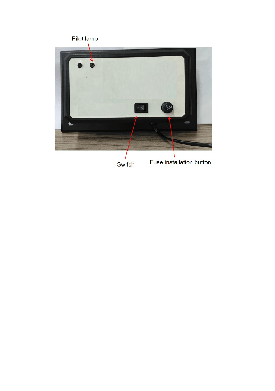
11
Lampen reinigen en vervangen
minste 15 minuten afkoelen voordat u het apparaat weer aanzet.
verwijder de eenheid.
2. Verwijder de 4 plaatmetalen schroeven en schuif de unit uit de
buis werk.
3a. Schoonmaken: Houd de unit stevig vast en veeg de UV-lamp(en)
af met een zachte doek die is bevochtigd met glasreiniger. Als u het
glas met uw hand aanraakt, veeg dan alle vingerafdrukken of vuil
weg met een doek. Zorg ervoor dat de lamp schoon en droog is
voordat u de unit terug in de buis plaatst.
3b. Vervangen: Gebruik van een lamp die niet is goedgekeurd voor
het apparaat, maakt de garantie ongeldig en kan ernstig letsel of
schade veroorzaken. Houd het apparaat stevig vast en druk op de
ontgrendelingsknop van de lamp om de UV-lamp te verwijderen.
Plaats de nieuwe lamp in het apparaat door de lamp van de buiten
totdat de lamp op zijn plaats klikt. Als u de lamp met uw hand

12
aanraakt, veeg dan alle vingerafdrukken of vuil weg met een zachte,
vochtige doek. Zorg ervoor dat de lamp(en) schoon en droog is / zijn
voordat u de unit terug in de buis plaatst.
4. Plaats de unit terug in het leidingwerk en plaats de 4 plaatmetalen
schroeven terug. Draai de schroeven gelijkmatig aan totdat de unit
stevig op zijn plaats zit. NIET SCHROEVEN TE DRAAI AAN.
5. Sluit de stroom naar het HVAC-systeem weer aan en steek de
stekker van het apparaat weer in een geaard stopcontact.

13
1
Fabrikant: Shanghaimuxinmuyeyouxiangongsi
Adres: Shuangchenglu 803nong11hao1602A-1609shi, baoshanqu,
Sjanghai 200000 CN.
Geïmporteerd naar AUS: SIHAO PTY LTD. 1 ROKEVA
STREETEASTWOOD
NSW 2122 Australië
Geïmporteerd naar de VS: Sanven Technology Ltd. Suite 250, 9166
Anaheim
Plaats, Rancho Cucamonga, CA 91730
REP
UK
YH CONSULTING LIMITED. C/O YH Consulting
Limited Office 147, Centurion House, London
Road, Staines-upon-Thames, Surrey, TW18 4AX
REP
EC
E-CrossStu GmbH
Mainzer Landstr.69,
60329 Frankfurt am Main.

2

3


5
Teknisk Support och e-garanticertifikat www.vevor.com/support
HVAC LUFTRENARE
MODELL: 2112-UV36/ 2006-UV9X2/2112-UV36X2
Vi fortsätter att vara engagerade i att ge dig verktyg till konkurrenskraftiga priser.
"Spara hälften", "Halva priset" eller andra liknande uttryck som endast används av oss
representerar en uppskattning av besparingar du kan dra nytta av att köpa vissa verktyg
med oss jämfört med de stora toppmärkena och betyder inte nödvändigtvis att täcka
alla kategorier av verktyg som vi erbjuder. Du påminns vänligen om att verifiera försiktigt
när du gör en beställning hos oss om du faktiskt gör det Sparande
Halv i jämförelse med de främsta varumärkena.

6


1
Modell : 2112-UV36/2006-UV9X2/2112-UV36X2
BEHÖVER HJÄLP? KONTAKTA OSS!
Har du produktfrågor? Behöver du teknisk support? Kontakta oss
gärna:
Teknisk support och e-garanticertifikat
www.vevor.com/support
Detta är den ursprungliga instruktionen, läs alla instruktioner noggrant
innan du använder den. VEVOR reserverar sig för en tydlig tolkning av vår
användarmanual. Utseendet på produkten är beroende av den produkt du
fått. Ursäkta oss att vi inte kommer att informera dig igen om det finns
någon teknik eller mjukvaruuppdateringar på vår produkt.
HVAC AIR PURIFIER

2
SÄKERHETSINSTRUKTIONER
1. Läs och förstå denna bruksanvisning noggrant innan du använder HVAC
luftrenare .
2. Installationen ska utföras av en vuxen och barn ska inte använda den
utan tillsyn.
3. UV - ljus är skadligt för exponerad hud och ögon och orsakar tillfällig
eller permanent blindhet. Titta aldrig rakt på UV-ljuset.
4. Koppla bort strömmen innan du installerar eller byter ut UV-lampan,
annars kan det orsaka stötar och dödsfall.
5. Använd handskar och installera HVAC luftrenare för att undvika skärsår
under installationen.
6. Transport Observera: Under transport ska förpackningen stå upprätt,
hanteras med försiktighet, förhindra stark stöt, vibration, extrudering.
7. Modifiera inte enheten på något sätt. Alla modifieringar kan skada
enheten eller göra den farlig för andra.
8.Reparera eller underhåll bör endast utföras av en kvalificerad person.
9. Endast den märkspänning som anges i denna manual kan användas.
10.Använd inte denna produkt i köket, där den oljiga ångan kan förkorta
lampornas livslängd.
11. Använd inte denna produkt i områden med sura, alkaliska eller andra
organiska gaser där det kan orsaka brand .
12. Använd inte denna produkt på brandfarliga och explosiva platser,
annars kommer det att orsaka brand.
13. Produkten kan endast tas isär efter att produkten har stängts i 15
minuter.
14. Lampröret innehåller kvicksilver och måste hanteras korrekt.
15. Rengör inte de trasiga lamporna med en dammsugare.
16. Produkten är inte vattentät, kan inte vara produkten som ska installeras
i en luftfuktare eller annan våt miljö .
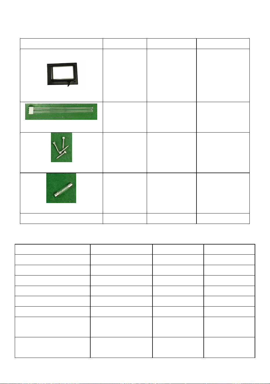
3
Lista över satsdelar
Modell
2112-UV36
2006-UV9X2
2112-UV36X2
UV-enhet
1 st
1 st
1 st
UV-lampa
2 st
4 st
4 st
skruva
4 st
4 st
4 st
Spara 2A säkringen
1 st
/
1 st
Positioneringsmall
1 st
1 st
1 st
PARAMETERLISTA
Modell
2112-UV36
2006-UV9X2
2112-UV36X2
Driva
36W
18W
72
Ljusrörets längd
411 mm
145 mm
411 mm
Ljus våglängd
254 nm
254 nm
254 nm
UV-livslängd
13000 timmar
13000 timmar
13000 timmar
Montering lamprör
1 st
2 st
2 st
Standby lamprör
1 st
2 st
2 st
Amerikansk
standardingång
AC120 V 60Hz
AC120 V 60Hz
AC120 V 60Hz
Europeisk version
Ingång
AC230 V 50Hz
AC230 V 50Hz
AC230 V 50Hz
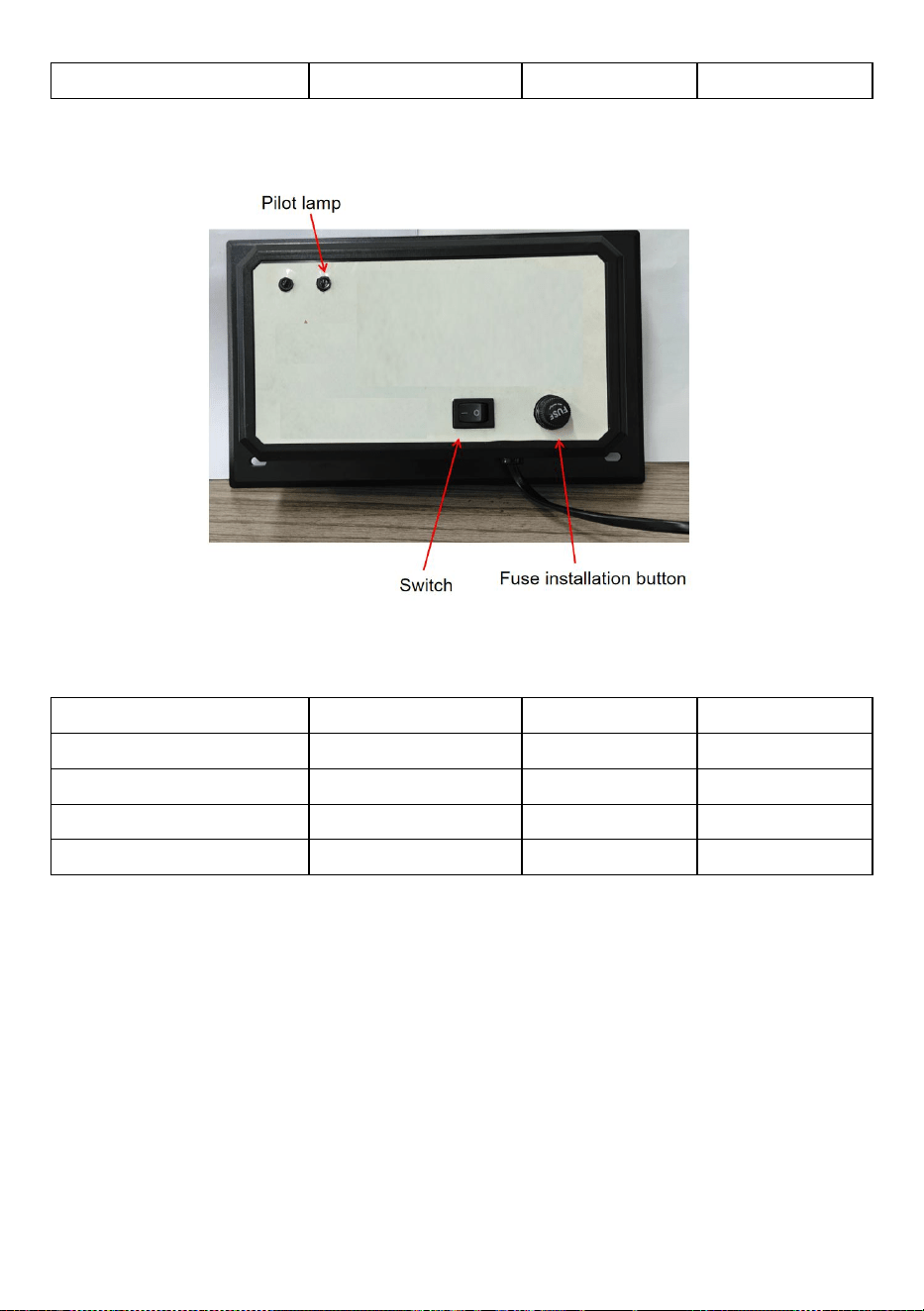
4
Effektivt område
1500 fot²
600 fot²
2400 fot²
Obs: Varje modell av märkströmförsörjning har AC120V och AC230V.
Notera spännings- och frekvensinformationen på produktens märkskylt.
Produktstorlek
Modell
2112-UV36
2006-UV9X2
2112-UV36X2
AA
492 mm
217 mm
498 mm
BB
Cirka 411 mm
Cirka 145 mm
Cirka 411 mm
CC
156 mm
126 mm
156 nm
DD
258 mm
175 mm
258 mm

5
Notera: Vänligen notera om det inre utrymmet på HVAC-röret kan rymma
produkten.
Installationsinstruktioner
Så här installerar du ditt UV-luftbehandlingssystem
Om ditt värme/kyla (HVAC) system är utrustat med luft konditionering,
rekommenderas att UV Luftbehandlingssystem (enhet) monteras direkt
ovanför kylbatteriet. Enheten kan förhindra tillväxt av en hög andel
mikroorganismer som mögel, bakterier och virus på ytor som kylslingor,
avloppskärl och kanalarbeten.
Välja monteringsplats
1. Enheten kan monteras i valfri riktning, men bör monteras så att
indikatorlampan kan ses.
2. Välj en plats som gör det enkelt att byta/rengöra UV-lamporna.
3. Installera enheten på en plan yta av kanalarbetet Ovanför
luftkonditioneringen kylslinga ("A Coil") om din VVS systemet har
luftkonditionering. Om ditt VVS-system inte har luftkonditionering bör
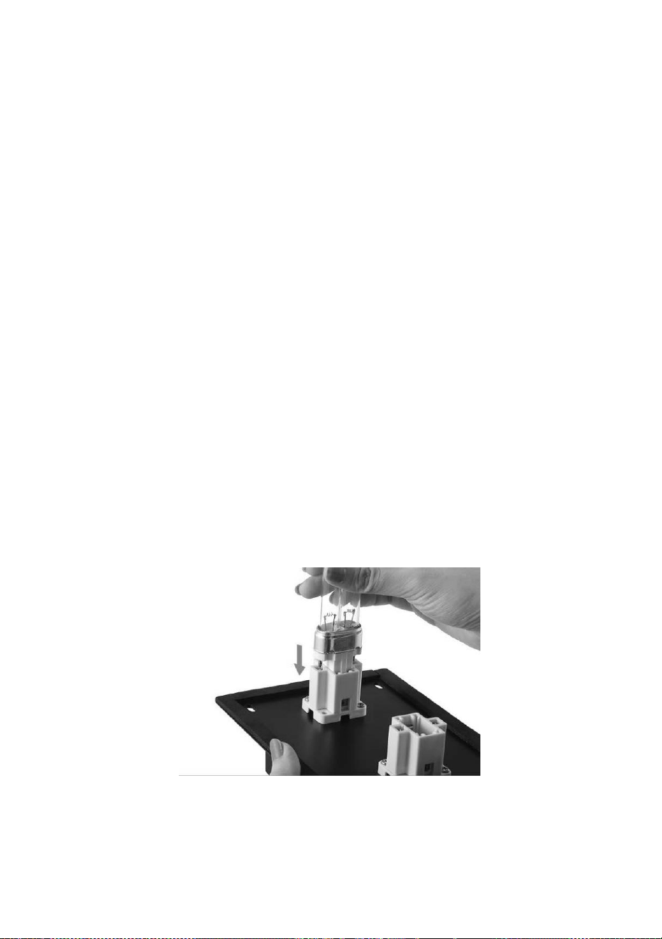
6
enheten installeras på tilluftskanalen om möjligt. Aggregatet kan vid behov
monteras på en returluftskanal
VARNING: Installera inte enheten i "A-spolen" eller under en
luftfuktare eftersom skada kan uppstå.
Om du är osäker på om du har valt en korrekt monteringsplats, se
bruksanvisningen för ditt VVS-system eller ring en kvalificerad fackman för
hjälp.
4 . Se till att placera enheten borta från plast- eller gummikomponenter
som kan skadas av UV-ljus. Om monteringsmöjligheterna är begränsade
kan plast och gummi täckas med tejp av aluminiumfolie för att skydda dem
från UV-ljus.
5. Enheten har en 4,92 fot nätsladd som måste installeras i ett jordat
eluttag; om det inte finns något eluttag i nätsladden, be en kvalificerad
fackman att installera ett ordentligt jordat eluttag.
Produktens spänningsreferens produktnamnskylt.
Installationssteg
1 . Installera glödlampor genom att skjuta in dem från sidan tills
glödlampan snäpper på plats .
Obs: 2112-UV36 är en glödlampa, 2006-UV9X2 och 2112-UV36X2 är två
glödlampor.
2 . Koppla ut strömmen till HVAC - systemet innan du installerar
enheten .
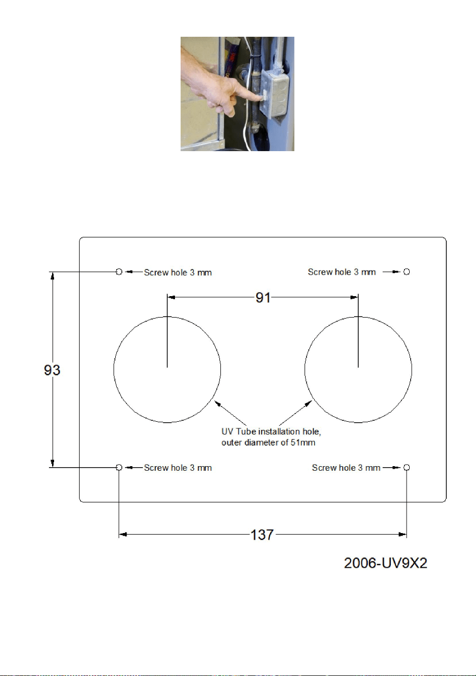
7
3A. Se positioneringsmallen 2006-UV9X2, rita först läget för
installationshålet med ett slag på rörets yttre vägg, inklusive 2 lamprörhål
med en ytterdiameter på 51 mm och 4 skruvhål på 3 mm; Bearbeta hål
med en skärmaskin och 3 mm borr .
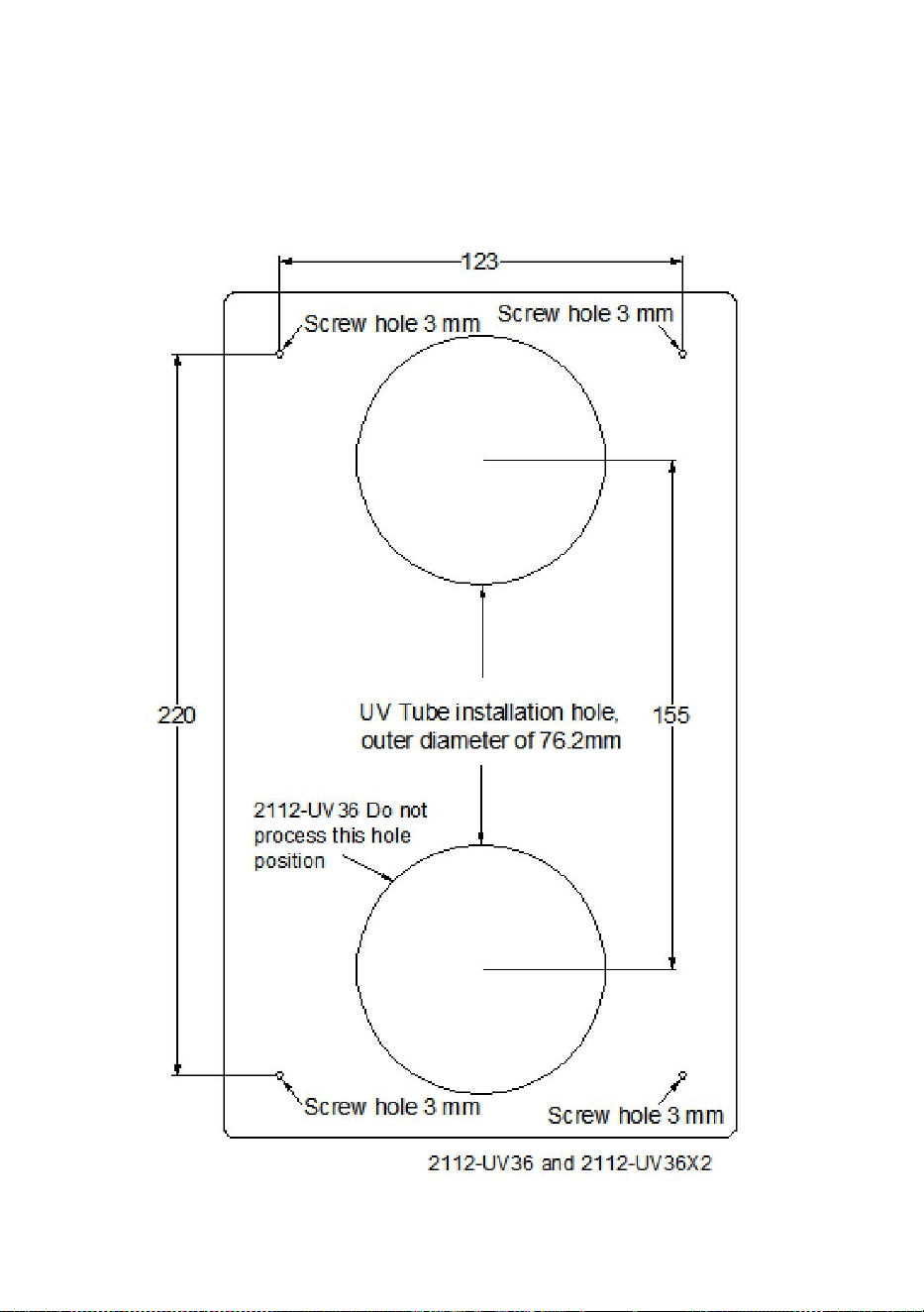
8
3B. Se positioneringsmallen 2112-UV36X2 , rita först läget för
installationshålet med ett slag på rörets yttervägg, inklusive 2 lamprörhål
med en ytterdiameter på 76,2 mm och 4 skruvhål på 3 mm; Bearbeta hål
med en skärmaskin och 3 mm borr .
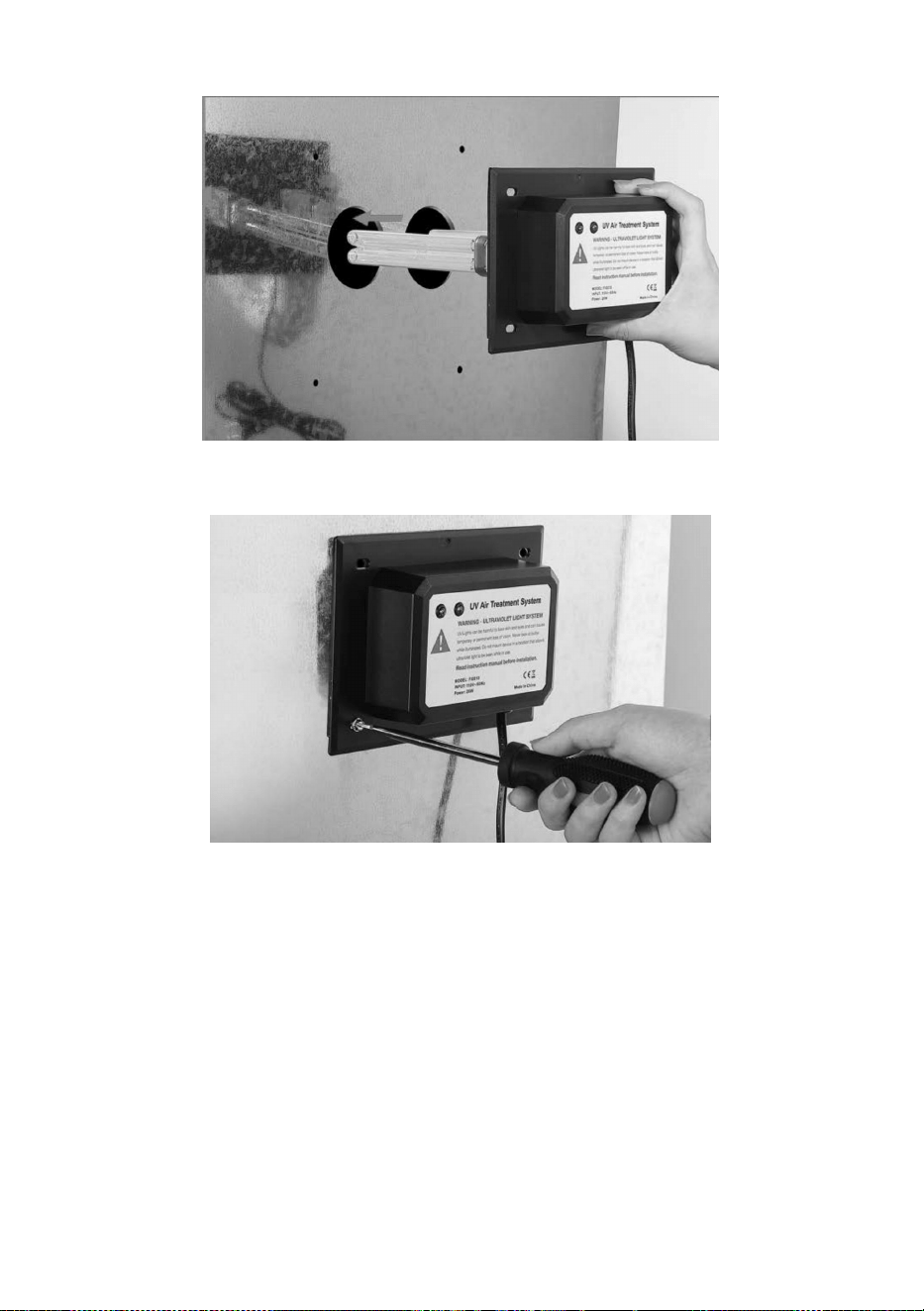
9
31. Sätt in UV-lampan i förborrhålet för att installera UV-lampan.
32. Installera UV-lampan på ytan av HVAC-röret med 4 skruvar.
33. Anslut nätkontakten till nätaggregatet, slå på UV-enhetens omkopplare
och tänd maskinens indikatorlampa. Maskinen började fungera.
34. Dra ur strömkontakten , skruva av säkringsvredet för att byta ut
2A-säkringen.
Varje modell av märkströmförsörjning har AC120V och AC230V. Notera
spännings- och frekvensinformationen på produktens märkskylt.
Obs: 2006-UV9X2 har ingen omkopplare, strömförsörjningen startar; och
säkringen kan inte bytas ut.
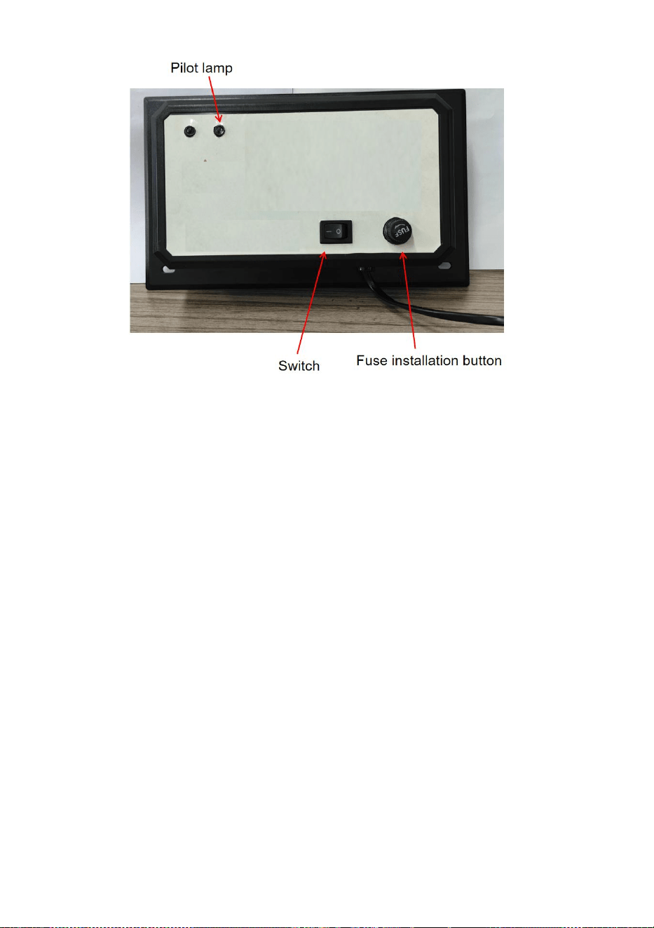
10
Rengöring och byte av lampor
1. Koppla bort strömmen till VVS-systemet, koppla ur enheten och
låt UV-lamporna svalna i minst 15 minuter innan du försöker ta bort
enheten.
2. Ta bort 4 plåtskruvar och skjut ut enheten ur kanalen arbete.
3a. Att rengöra: Håll enheten ordentligt och torka av UV-lamporna
med en mjuk trasa fuktad med glasrengöringsmedel. Om du rör vid
glaset med handen, se till att torka bort eventuella fingeravtryck eller
smuts med en trasa. Se till att glödlampan är ren och torr innan du
installerar enheten tillbaka i kanalen.
3b. Att byta ut: Användning av en glödlampa som inte är godkänd för
enheten upphäver garantin och kan orsaka allvarlig skada eller
skada. Håll enheten ordentligt och tryck på lampans frigöringsknapp
för att ta bort UV-lampan. Installera den nya glödlampan i enheten
genom att skjuta in glödlampan från lampan utanför tills glödlampan
snäpper på plats. Om du rör glödlampan med handen, var noga med
att torka bort eventuella fingeravtryck eller smuts med en mjuk fuktig

11
trasa. Se till att glödlamporna är rena och torra innan du installerar
enheten tillbaka i kanalen.
4. Sätt tillbaka enheten i kanalsystemet och sätt tillbaka de 4
plåtskruvarna. Dra åt skruvarna jämnt tills enheten sitter säkert på
plats. GÖR INTE ÖVERDRÄCK SKRUVAR.
5. Koppla tillbaka strömmen till VVS-systemet och anslut tillbaka
enheten till ett jordat eluttag.

Tillverkare: Shanghaimuxinmuyeyouxiangongsi
Adress: Shuangchenglu 803nong11hao1602A-1609shi, baoshanqu,
shanghai 200 000 CN.
Importerad till AUS: SIHAO PTY LTD. 1 ROKEVA STREETEASTWOOD
NSW 2122 Australien
Importerad till USA: Sanven Technology Ltd. Suite 250, 9166 Anaheim
Place, Rancho Cucamonga, CA 91730
REP
UK
YH CONSULTING LIMITED. C/O YH Consulting
Limited Office 147, Centurion House, London
Road, Staines-upon-Thames, Surrey, TW18 4AX
REP
EC
E-CrossStu GmbH
Mainzer Landstr.69,
60329 Frankfurt am Main.