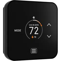
TQ1 Smart Thermostat
Installaon and
instrucon manual
Important!
• Please read the
instrucons
• Disconnect power
before starng work
• Take a photo of your
exisng thermostat
wiring
Help!
If you get stuck, please visit www.luxproducts.com/support for
addional videos and support material
C-wire
This thermostat requires a C-wire or a Power Bridge. If your
exisng thermostat does not use a C-wire, please either pur-
chase a Power Bridge (available at luxproducts.com) or contact
an HVAC professional.
System compability
This thermostat is for most 24VAC systems. It is not compa-
ble with 120-240VAC heang. If you see thick red or black
wires, “line voltage”, or wire nuts, STOP!
What is included?
TQ1 thermostat
Self-tapping screws
wall anchors
Wiring
labels
Tools needed
Phillips screwdriver
Maer-enabled Smart
Speaker (oponal)
FCC Statement
This device complies with Part 15 of the FCC Rules Operaon is subject to the following two condions:
(1) this device may not cause harmful interference, and (2) this device must accept any interference
received, including interference that may cause undesired operaon.
Warning: Changes or modicaons to this unit not expressly approved by the party responsible for
compliance could void the user’s authority to operate the equipment.
NOTE: This equipment has been tested and found to comply with the limits for a Class B digital device,
pursuant to Part 15 of the FCC Rules. These limits are designed to provide reasonable protecon against
harmful interference in a residenal installaon. This equipment generates, uses and can radiate radio
frequency energy and, if not installed and used in accordance with the instrucons, may cause harmful
interference to radio communicaons. However, there is no guarantee that interference will not occur in
a parcular installaon. If this equipment does cause harmful interference to radio or television recep-
on, which can be determined by turning the equipment o and on, the user is encouraged to try to
correct the interference by one or more of the following measures:
• Reorient or relocate the receiving antenna.
• Increase the separaon between the equipment and receiver.
• Connect the equipment into an outlet on a circuit dierent from that to which the receiver is connect-
ed.
• Consult the dealer or an experienced radio/TV technician for help.
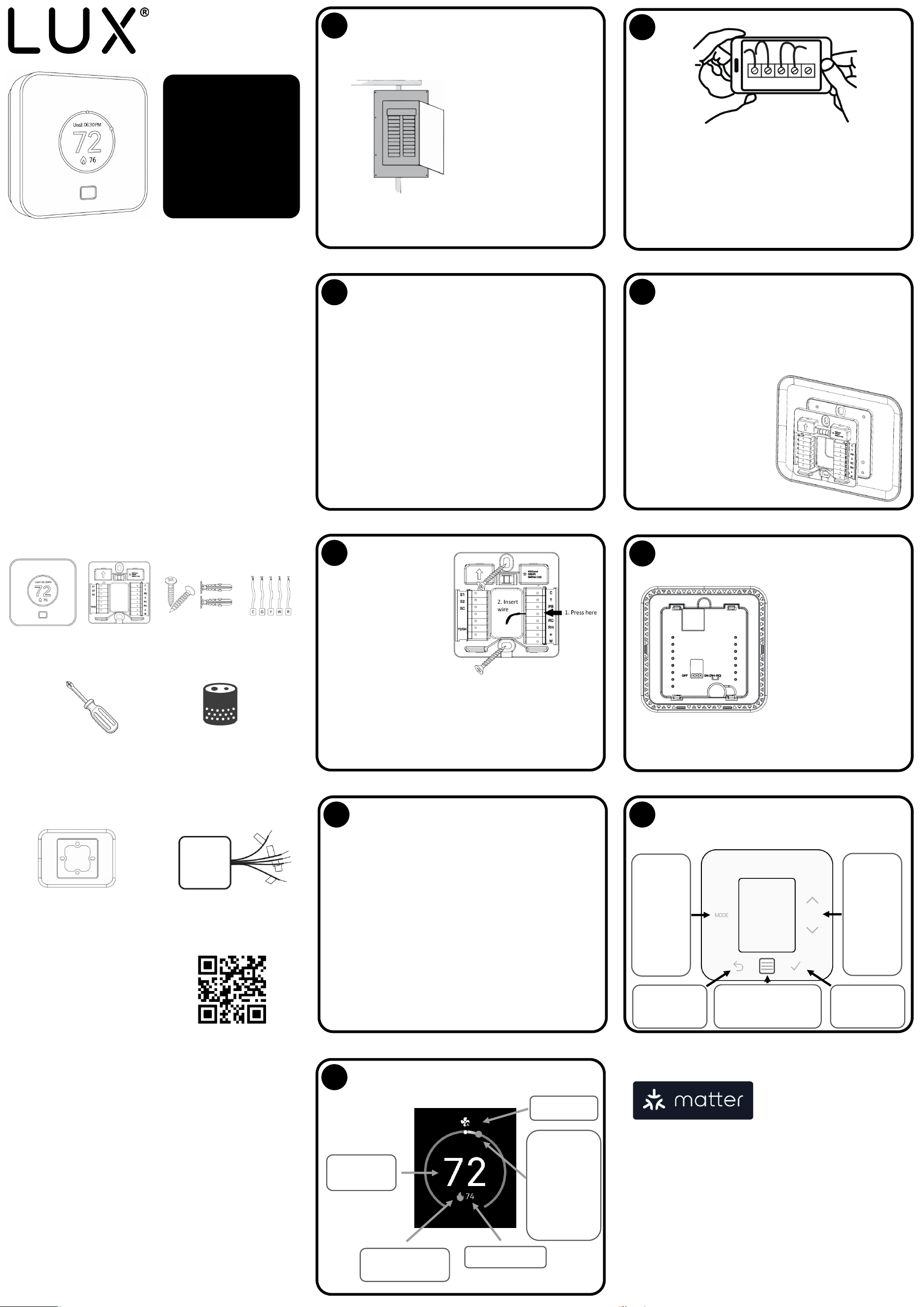
1
Turn-o the power at the
circuit breaker to both
your heang and cooling
systems before
performing any wiring.
2
Remove the front part of your old thermostat from the
back part.
If the wires are not already labelled, use the provided
wiring labels to mark each one.
Take a photo of the wiring as this may help you later.
3
The most typical installaons include;
• Convenonal 1H/1C (Y, G, W, R, C)
• Convenonal 2H/1C (Y, G, W, W2, R, C)
• Heat Pump Single-Stage (Y, G, R, O/B, C)
• Heat Pump with auxiliary heat (Y, G, R, O/B, W, C)
If you have only one R wire, please use the RH terminal.
For more advanced system conguraons, please see the
wiring diagram on reverse side.
4
Unscrew the screws holding the old thermostat base plate
to the wall, remove the wires from the terminals of your
old thermostat taking care not to let them fall back into the
wall.
(Oponal) If you have a deco-
rave trim plate, you should
place it between the wall and
the wall plate now. Note that
you can install it vercally or
horizontally depending on
your preference.
Not included
Decorave trim plate to
cover rough edges of dry
wall
Lux Power Bridge in case the
wiring to thermostat does
not have a “c-wire”
If you need these parts for your
installaon, please visit
www.luxproducts.com
Wall plate
5
Make sure the arrow on
the wall plate is poinng
up and insert each of the
wires into the terminals.
Press lever then insert
corresponding wire.
Once all the wires are secure,
screw self-tapping screws in
to the top and boom mounng holes of the wall plate;
use the bubble level to ensure the wall plate is straight
before ghtening.
6
If your system has both
RC and RH terminals;
locate the red jumper
on the back of the ther-
mostat, and move it to
the OFF posion
(covering the le and
center pins).
7
You can now mount your TQ1 thermostat on to the
wall plate.
Ensure that the thermostat is the right way up
(terminal pins at the boom), align the thermostat
over the terminals and push rmly. The thermostat
should snap into place.
You may now return the power to your HVAC system
and your TQ1 thermostat will power-up. The user
menu will navigate you through the rest of the set-up
process.
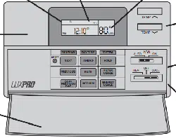
8
The TQ1 has 6 illuminated buons to navigate
menus and change sengs.
Selecng
heat, cool,
auto
MODE,
changing
fan sengs
or turning
the system
o
Going BACK in
the menu
Waking-up the screen
and accessing the
main MENU
Conrming OK
selecon
Changing
the set
tempera-
ture UP or
DOWN,
and navi-
gang the
menus
The TQ1 is compable with all
Maer-enabled controllers,
this includes the smart-
speakers from you favourite
brands. In order to get con-
nected, press the ‘menu’ buon on TQ1 and select
‘Connecvity’. Open the ‘Add device’ opon inside your pre-
ferred smart-home app and scan the QR code.
Most smart-home apps allow you to create ‘scenes’ or
‘automaons’ depending on events (like coming home) or
me of day. When the TQ1 receives this instrucon, it will go
to the desired mode and temperature.
If you set a schedule on the TQ1, then the TQ1 will return to
its schedule at the next set-
point change.
EME Americas
124 Broadkill Road, Milton DE, 19968
© 2025 EME Delaware Inc.
9
The TQ1 displays all the informaon you need to
know about your HVAC
Current room
temperature
Heang/ cooling
status icon
Set temperature
The distance
between the
white dot and
colour dot
shows how
much heang/
cooling is
needed
Fan mode
v03
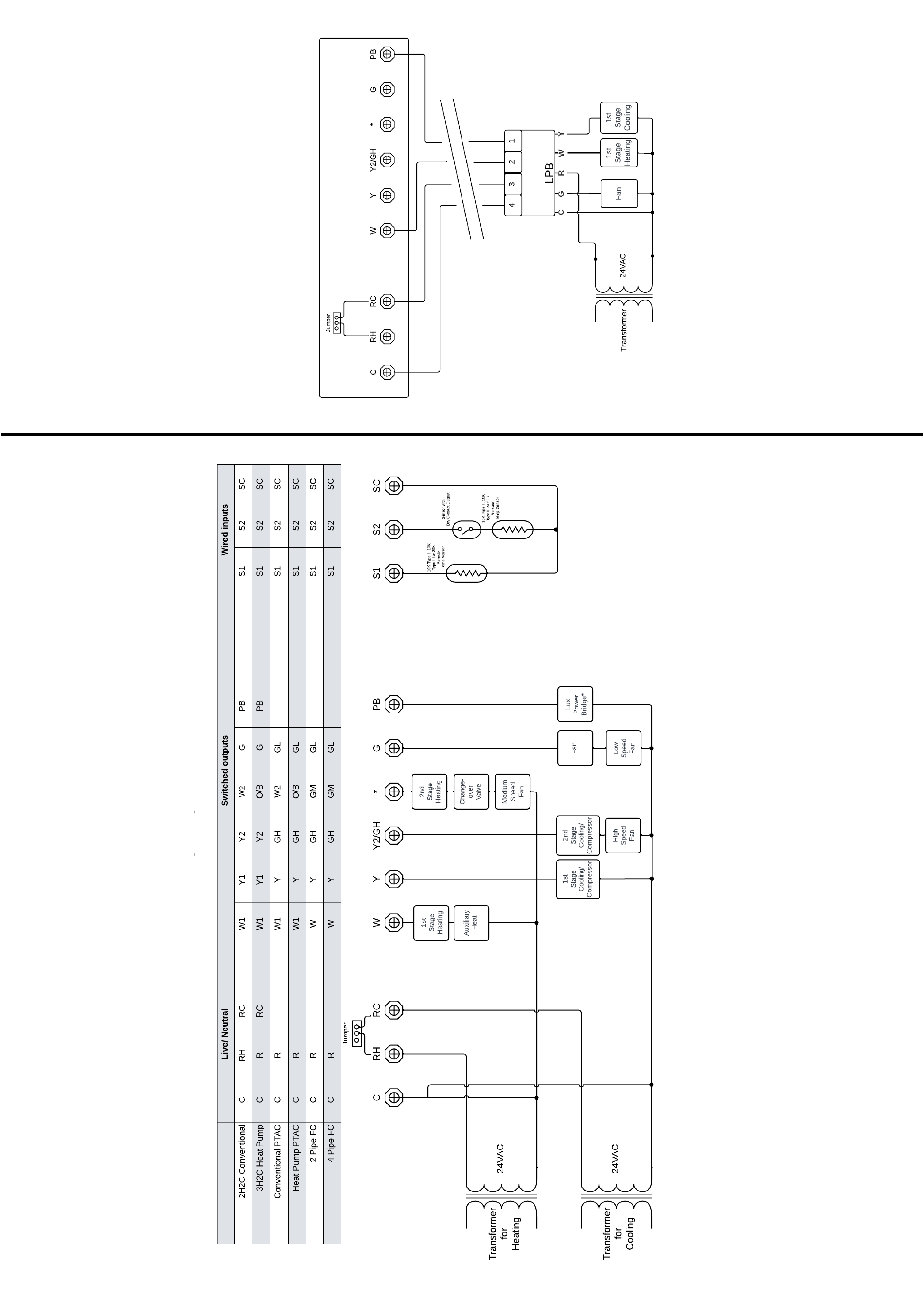
Wiring chart for all system types
Wiring chart for 1 heat, 1 cool convenonal
system with Lux Power Bridge
Electrical Rangs
Power source: 19
-30 VAC @50/60Hz, 40 VA, Class 2 or SELV
Output Rang: 1.0A resisve load per terminal, 5.0A resisve
load combined total
Wire: Solid 18
-22AWG, Stranded 20
-22 AWG