1
Installation Guide
AT-HDR-EX-70-2PS
4K HDR HDMI Over HDBaseT TX/RX Kit
AT-HDR-EX-70-2PS
The Atlona AT-HDR-EX-70-2PS is an HDBaseT transmitter/receiver kit for high dynamic range
(HDR) formats. The kit is HDCP 2.2 compliant and supports 4K/UHD video @ 60 Hz with 4:4:4
chroma sampling, as well as HDMI data rates up to 18 Gbps. The HDR-EX-70-2PS provides
HDMI transmission up to 230 feet (70 meters) for 1080p video, and up to 130 feet (40 meters)
for 4K HDR over CAT6a/7 cable. This extender kit features visually lossless compression with no
latency to enable HDR and 4K/60 4:4:4 video signal extension over HDBaseT. The HDR-EX-70-
2PS delivers a cost-eective solution for HDMI extension, with locally powered transmitter and
receiver endpoints as well as surface mounting hardware for discreet installation.
The HDR-EX-70-2PS is ideal for residential applications with the latest as well as emerging 4K/
UHD and HDR sources and displays. It is compatible with all video resolutions, audio formats,
and color space formats supported in the HDMI 2.0a specication, plus the ability to pass
metadata for HDR content. The HDR-EX-70-2PS includes Atlona’s award-winning 10 year limited
product warranty and customer support services, so that integrators can specify, purchase, and
install with condence.
IMPORTANT: Visit https://atlona.com/product/AT-HDR-EX-70-2PS/ for the latest rm-
ware updates and Installation Guide.
1 x AT-HDR-EX-70-2PS-TX
1 x AT-HDR-EX-70-2PS-RX
4 x Mounting brackets
8 x Mounting screws
2 x 5 V DC power supplies
1 x Installation Guide
Package Contents
2
Installation Guide
AT-HDR-EX-70-2PS
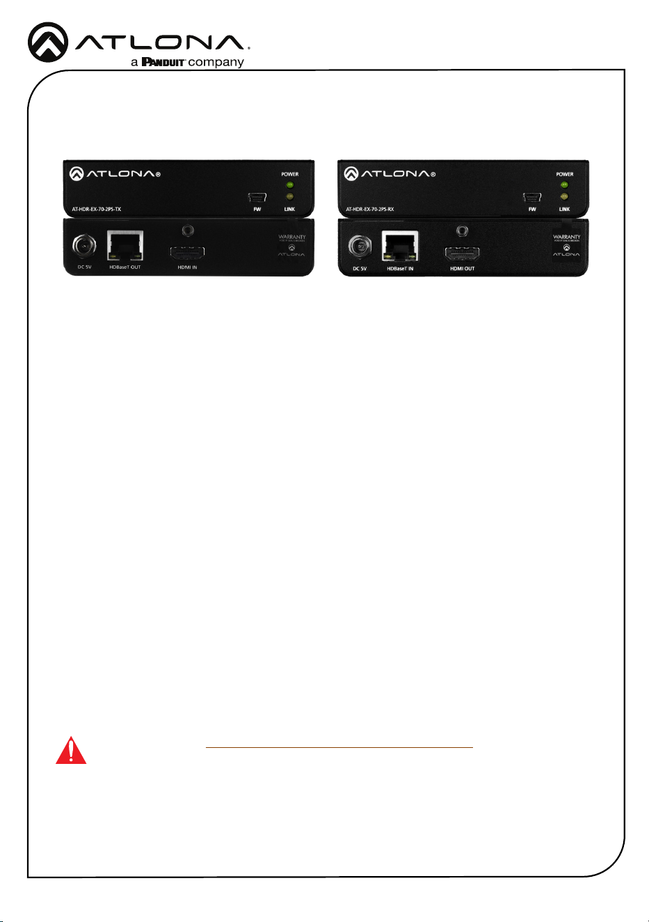
FW
AT-HDR-EX-70-2PS-TX
POWER
LINK
DC 5V HDBaseT OUT HDMI IN
ON
1
FW
UNIT HDBaseT
FW
AT-HDR-EX-70-2PS-TX
POWER
LINK
DC 5V HDBaseT OUT HDMI IN
ON
1
FW
UNIT HDBaseT
FW
AT-HDR-EX-70-2PS-TX
POWER
LINK
DC 5V HDBaseT OUT HDMI IN
ON
1
FW
UNIT HDBaseT
FW
AT-HDR-EX-70-2PS-RX
POWER
LINK
DC 5V HDBaseT IN HDMI OUT
ON
1
FW
UNIT HDBaseT
FW
AT-HDR-EX-70-2PS-RX
POWER
LINK
DC 5V HDBaseT IN HDMI OUT
ON
1
FW
UNIT HDBaseT
FW
AT-HDR-EX-70-2PS-RX
POWER
LINK
DC 5V HDBaseT IN HDMI OUT
ON
1
FW
UNIT HDBaseT
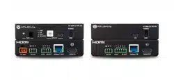
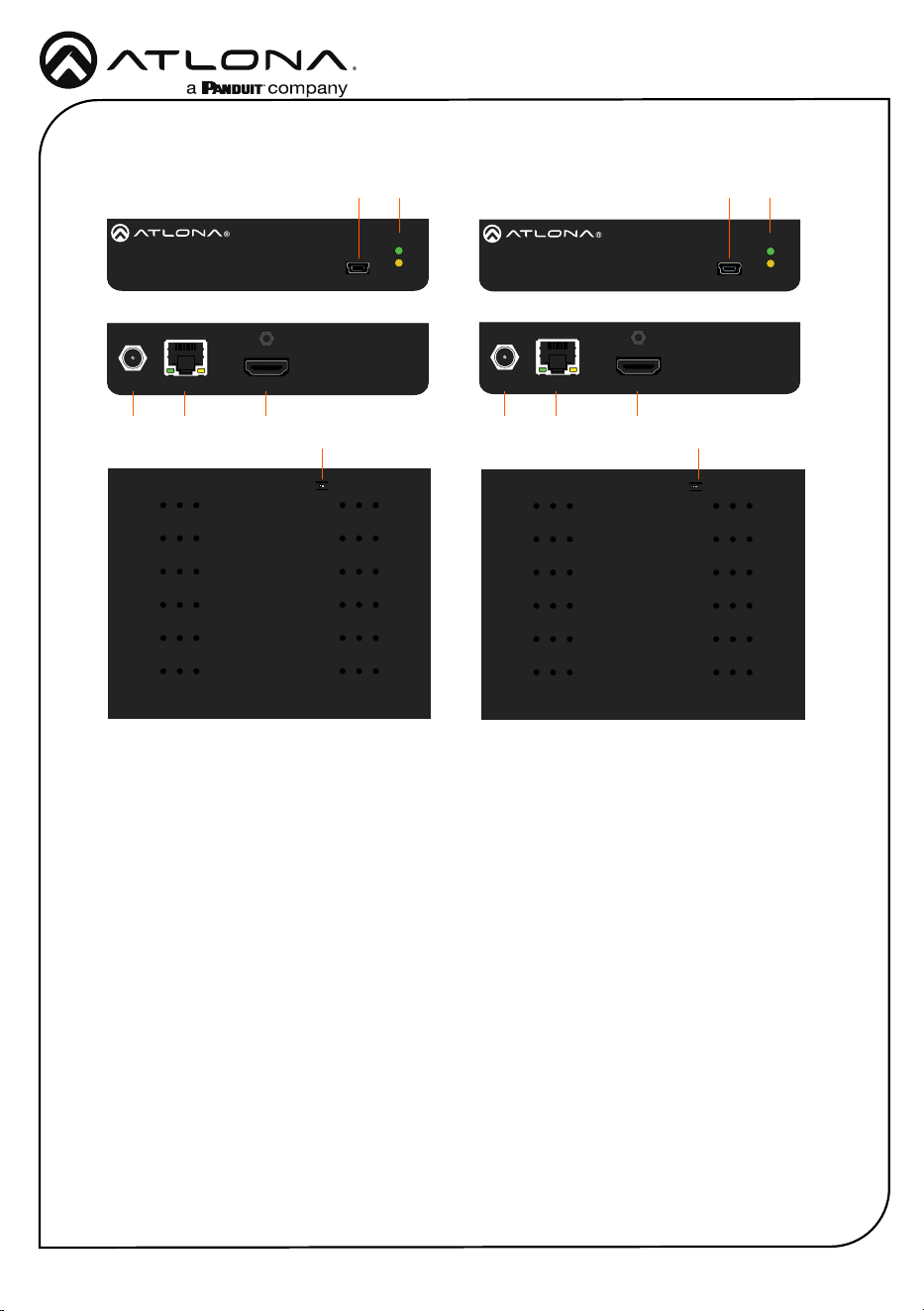
Panel Descriptions
1 FW
Connect a mini-USB to USB-A type cable
from this port to a computer, to update
the rmware.
2 POWER and LINK LEDs
The power LED will illuminate green when
receiving power. The link LED will glow
yellow when signal is being sent/received
between the transmitter and the receiver.
3 DC 5V
Connect the included power supply to this
power receptacle.
4 HDBaseT OUT
Connect an Ethernet cable from this port
to the HDBaseT IN port on the receiver.
5 HDMI IN
Connect an HDMI cable from this port to a
UHD/HD source.
6 HDBaseT IN
Connect an Ethernet cable from this
port to the HDBaseT OUT port on the
transmitter.
7 HDMI OUT
Connect an HDMI cable from this port to
an UHD/HD display.
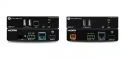
8 FW (UNIT / HDBaseT)
Set this switch to the UNIT position to
update the rmware. For normal operation
or for HDBaseT cable testing, set to the
HDBaseT position.
Transmitter
Front Front
Rear Rear
Bottom Bottom
Receiver
3
3
4
6
5
7
2
8
8
21 1
3
Installation Guide
AT-HDR-EX-70-2PS
1. Connect a UHD/HD source to the HDMI IN port on the AT-HDR-EX-70-2PS-TX.
2. Connect a UHD/HD display to the HDMI OUT port on the AT-HDR-EX-70-2PS-RX.
3. Connect an Ethernet cable, from the HDBaseT OUT port on the AT-HDR-EX-70-2PS-TX,
to the HDBaseT IN port on the AT-HDR-EX-70-2PS-RX.
4. Connect each of the included 5 V DC power supplies to the DC 5V locking power
receptacles on both the AT-HDR-EX-70-2PS-TX and AT-HDR-EX-70-2PS-RX.
5. Connect each of the power supplies to an available AC outlet.
Installation
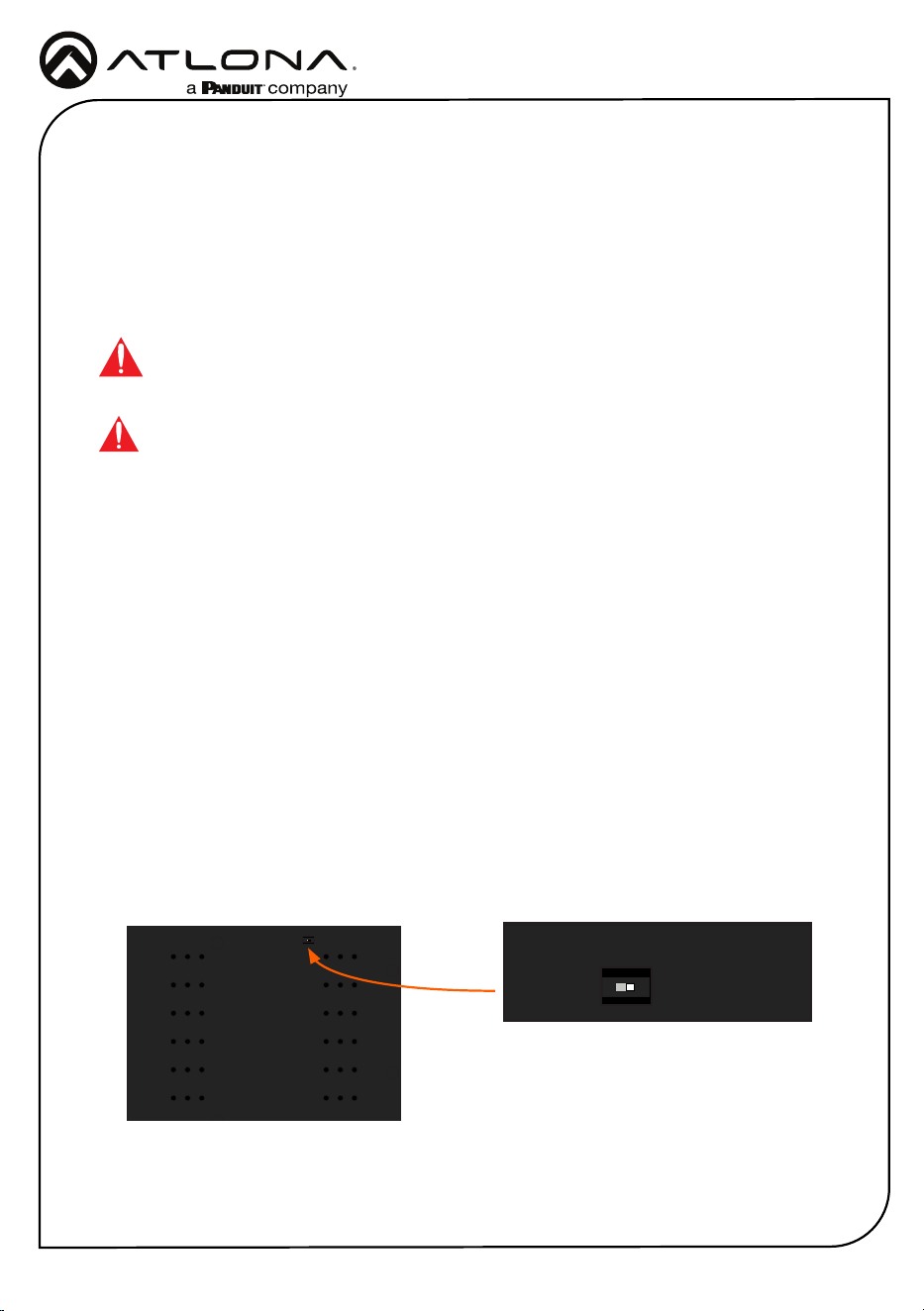
IMPORTANT: The DIP switch, on the bottom of both the transmitter and receiver,
must be set to HDBaseT mode for normal operation. If this is not the case, then
disconnect power from the unit, set the DIP switch to HDBaseT mode, and then
reconnect the power.
IMPORTANT: Do not over-tighten or apply high-torque devices to the locking
connector. Doing so may damage the power receptacle and/or locking connector.
Testing HDBaseT Signal Integrity
The AT-HDR-EX-70-2PS Analyzer is a free, downloadable software application that is used to
test the signal integrity of HDBaseT cables. The software is available from Atlona.com, on the
AT-HDR-EX-70-2PS product page.
1. Download and run the AT-HDR-EX-2PS Analyzer.exe le. The software comes with a
ConnectorTool.dll le. The DLL le must exist in the same folder as the executable, in order
for the software to run.
2. Verify that the DIP switch, on the bottom of the unit, is set to the HDBaseT position, as
shown below.
Requirements
• AT-HDR-EX-70-2PS-TX / AT-HDR-EX-70-2PS-RX
• AT-HDR-EX-70-2PS Analyzer software
• Computer running Microsoft Windows®
• USB-A to mini-B cable
FW
AT-HDR-EX-70-2PS-TX
POWER
LINK
DC 5V HDBaseT OUT HDMI IN
ON
1
FW
UNIT HDBaseT
FW
AT-HDR-EX-70-2PS-TX
POWER
LINK
DC 5V HDBaseT OUT HDMI IN
ON
1
FW
UNIT HDBaseT
4
Installation Guide
AT-HDR-EX-70-2PS
3. Reconnect power to both the
transmitter and receiver. Make
sure that a signal is passing
between the transmitter and the
receiver.
4. Set the DIP switch to the UNIT
position.
5. Connect a USB-A to USB mini-B
cable from the computer to the FW
port on either the transmitter or the
receiver.
FW
AT-HDR-EX-70-2PS-TX
POWER
LINK
DC 5V HDBaseT OUT HDMI IN
ON
1
FW
UNIT HDBaseT
FW port
When performing an HDBaseT test, connecting to either the transmitter or receiver will
provide the same results.
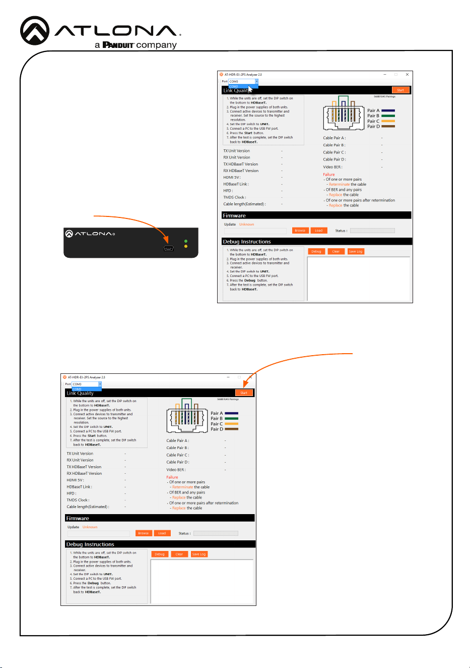
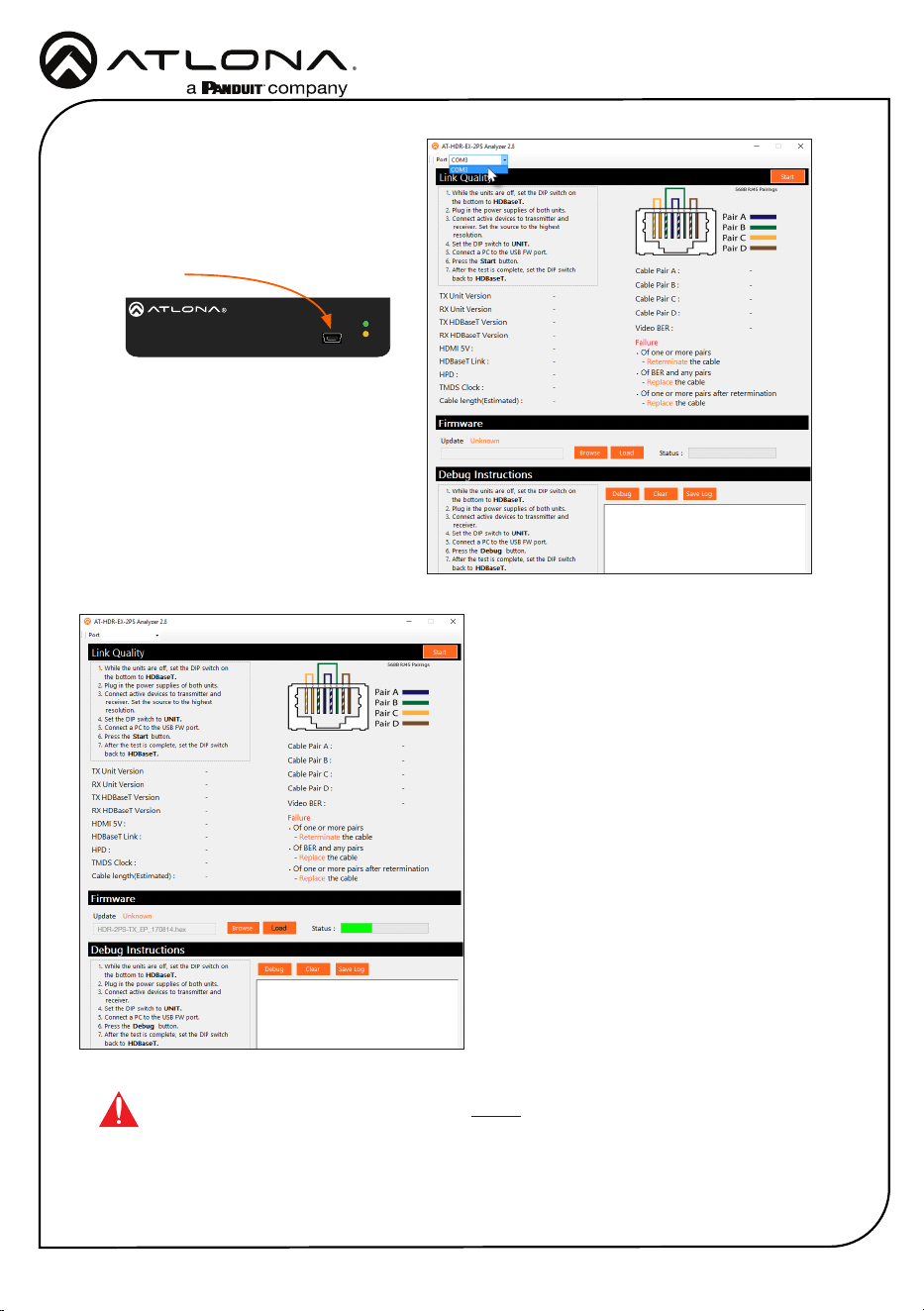
6. Launch the AT-HDR-EX-70-2PS Analyzer software.
7. Click the Start button.
• If the HDBaseT link integrity is
good, then all tests will display as
“Pass”.
• If any part of the HDBaseT cable
fails, then a numerical value, in
decibels, will be displayed next
to the associated pair, under the
Signal Quality section.
These values can be reported
to Atlona Technical Support
Engineers to help resolve possible
issues.
Start button
8. After testing is complete, set the
DIP switch on the bottom of the
unit to the HDBaseT position.
5
Installation Guide
AT-HDR-EX-70-2PS
Updating the Firmware
The follow procedure outlines the rmware update procedure and applies to both the transmitter
and receiver. Both the AT-HDR-EX-70-2PS rmware and analyzer software will be required for
this process and are available from Atlona.com on the AT-HDR-EX-70-2PS product web page.
1. Download and run the AT-HDR-EX-2PS Analyzer.exe le. The software comes with a
ConnectorTool.dll le. The DLL le must reside in the same folder as the executable, in order
for the software to run.
2. Disconnect power from the unit.
3. Set the DIP switch, on the bottom of the unit, to the UNIT position, as shown below.
Requirements
• AT-HDR-EX-70-2PS-TX / AT-HDR-EX-70-2PS-RX
• AT-HDR-EX-70-2PS Analyzer software
• Firmware le
• Computer running Microsoft Windows®
• USB-A to mini-B cable
FW
AT-HDR-EX-70-2PS-TX
POWER
LINK
DC 5V HDBaseT OUT HDMI IN
ON
1
FW
UNIT HDBaseT
FW
AT-HDR-EX-70-2PS-TX
POWER
LINK
DC 5V HDBaseT OUT HDMI IN
ON
1
FW
UNIT HDBaseT
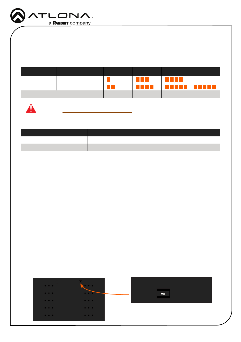
Refer to the tables below for recommended cabling when using Altona products with HDBaseT.
The green bars indicate the signal quality when using each type of cable. Higher-quality signals
are represented by more bars.
Cable Recommendation Guidelines
Core Shielding CAT5e CAT6 CAT6a CAT7
Solid UTP (unshielded) N/A
STP (shielded)
Performance Rating (MHz) 350 500 600 800
*Atlona recommends TIA/EIA 568-B termination for optimal performance.
Cable* Max. Distance @ 4K Max. Distance @ 1080p
CAT5e/6 115 feet (35 meters) 200 feet (60 meters)
CAT6a/7 130 feet (40 meters) 230 feet (70 meters)
IMPORTANT: It is recommended to use UTP6A (https://atlona.com/product/utp6a/)
and STP6X (https://atlona.com/product/stp6x/) if a stranded/patch cable is needed.
These cables have been tested and approved to work with these extenders for full
functionality.
6
Installation Guide
AT-HDR-EX-70-2PS
4. Connect a USB-A to USB mini-B
cable from the computer to the FW
port on the AT-HDR-EX-70-2PS.
5. Launch the AT-HDR-EX-70-2PS
Analyzer software.
6. Select the proper COM port from
the drop-down list, in the top-left
corner of the software screen.
FW
AT-HDR-EX-70-2PS-TX
POWER
LINK
DC 5V HDBaseT OUT HDMI IN
ON
1
FW
UNIT HDBaseT
FW port
9. Select the proper rmware le from the
location specied in step 6:
Transmitter: HDR-2PS-TX_VXX.hex
Receiver: HDR-2PS-RX_VXX.hex
10. Click the Open button on the dialog
box.
11. Click the Load button, within the AT-
HDR-EX-70-2PS Analyzer software, to
begin the rmware update procedure.
During the update process, the current
progress will be displayed in the
progress bar.
7. Extract the rmware, from the archive
le, to the Windows desktop or other
folder.
8. Click the Browse button within
the AT-HDR-EX-70-2PS Analyzer
software. The Open le dialog box
will be displayed.
13. Reconnect the power supply to the unit.
14. Repeat steps 2 though 13 for the other unit(s).
12. Once the upgrade process is complete,
set the DIP switch, on the bottom of the
unit, to the HDBaseT position.
IMPORTANT: The DIP switch, on the bottom of both the transmitter and
receiver, must be set to HDBaseT mode before reconnecting the power in order
to resume normal operation.
7
Installation Guide
AT-HDR-EX-70-2PS
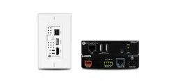
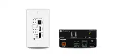
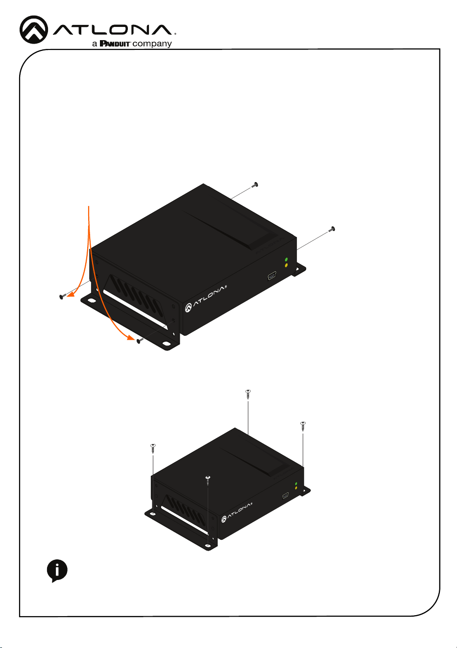
The AT-HDR-EX-70-2PS encoder includes two mounting brackets and four mounting screws,
which can be used to attach the unit to any at surface.
1. Position one of the mounting brackets, as shown below, aligning the holes on the side of the
enclosure with one set of holes on the mounting bracket.
2. Use the enclosure screws to secure the mounting bracket to the enclosure.
3. Repeat the above steps to attach the second mounting bracket to the opposite side of the
unit.
4. Mount the unit using the oval-shaped holes, on each mounting bracket. If using a drywall
surface, a #6 drywall screw is recommended.
NOTE: Mounting brackets can also be inverted to mount the unit under a table
or other at surface.
Mounting Instructions
FW
AT-HDR-EX-70-2PS-TX
POWER
LINK
FW
AT-HDR-EX-70-2PS-TX
POWER
LINK
Included screws
8
Installation Guide
AT-HDR-EX-70-2PS
Version 3
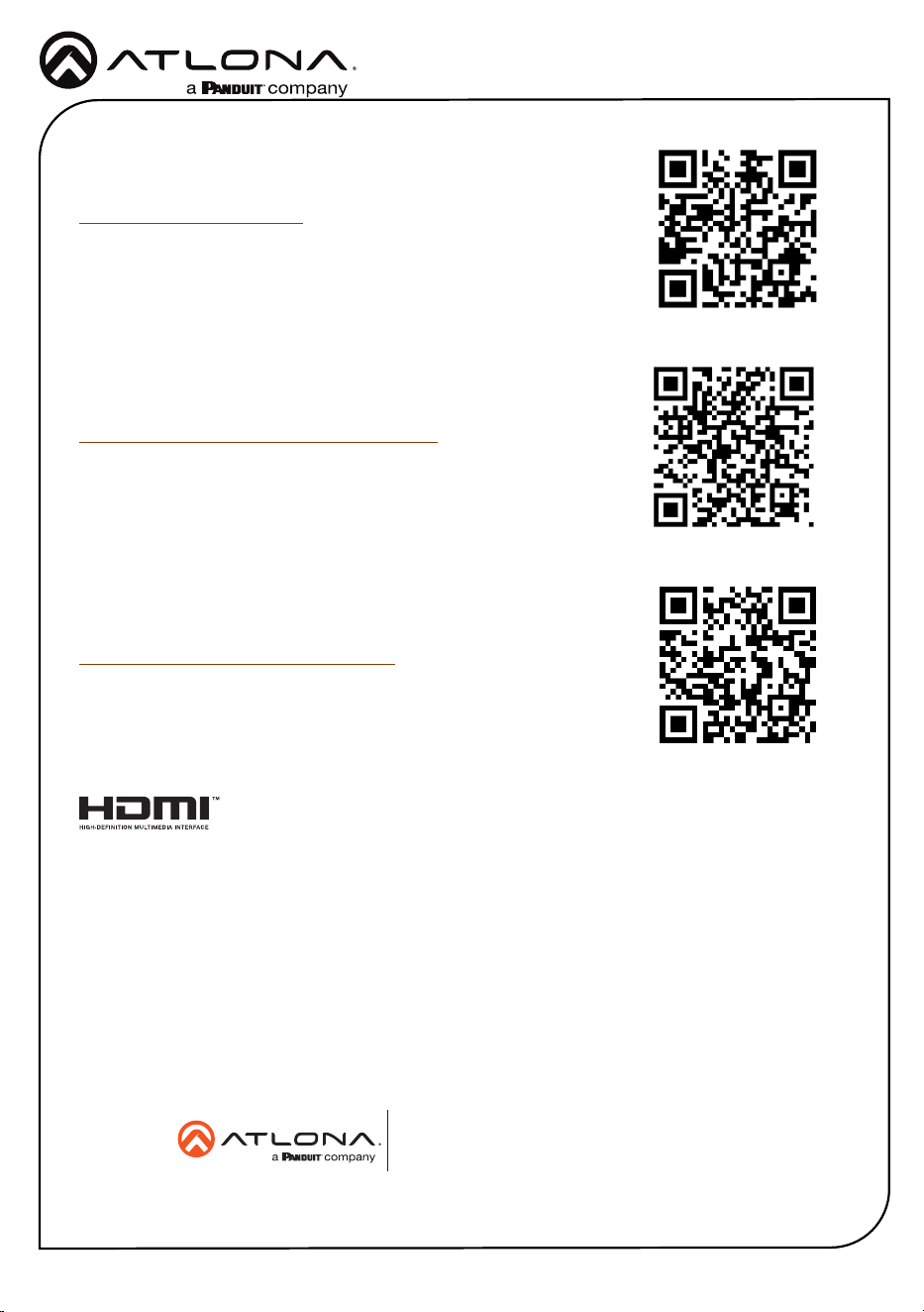
English Declaration of Conformity
The English version can be found under the resources tab at:
https://atlona.com/product/at-hdr-ex-70-2ps/.
© 2021 Atlona Inc. All rights reserved. “Atlona” and the Atlona logo are registered trademarks of Atlona Inc. All other brand names and trademarks or registered
trademarks are the property of their respective owners. Pricing, specications and availability subject to change without notice. Actual products, product images,
and online product images may vary from images shown here.
Toll free US International
atlona.com • 877.536.3976 • 41.43.508.4321
25161-R3
Warranty
Chinese Declaration of Conformity 中国RoHS合格声明
To view the product warranty, use the following link or QR code:
https://atlona.com/warranty/.
由SKU列出於:
https://atlona.com/about-us/china-rohs/.
The terms HDMI, HDMI High-Denition Multimedia Interface, and the HDMI Logo are trademarks or
registered trademarks of HDMI licensing Administrator, Inc.