11 3-90-30007467Vermont Castings • Stardance SDDVT Installation Manual_R40 • 09/25
DANGER
HOT GLASS WILL
CAUSE BURNS.
DO NOT TOUCH GLASS
UNTIL COOLED.
NEVER ALLOW CHILDREN
TO TOUCH GLASS.
A barrier designed to reduce the risk of burns from
the hot viewing glass is provided with this
appliance and must be installed.
CERTIFIED
S
AFETY BARRIER
FIRE OR EXPLOSION HAZARD
Failure to follow safety warnings exactly could result
in serious injury, death or property damage.
• Donotstoreorusegasolineorotherammable
vapors and liquids in the vicinity of this or any
other appliance.
• WHAT TO DO IF YOU SMELL GAS
– Do not try to light any appliance.
– Do not touch any electrical switch; do not use
anyphoneinyourbuilding.
–Leavethebuildingimmediately.
– Immediately call your gas supplier from a
neighbor’s phone. Follow the gas supplier’s
instructions.
– If you cannot reach your gas supplier, call the
redepartment.
• Installation and service must be performed
by a qualied installer, service agency or the
gas supplier.
NOTICE: SAVE THESE INSTRUCTIONS
Installation & Operating Manual
Installation and Appliance Setup - Care and Operation
INSTALLER:Leavethismanualwithpartyresponsibleforuseandoperation.
OWNER: Retain this manual for future reference.
Call your dealer for questions on Installation, Operation, or Service.
WARNING
Installation and service of this appliance should be performed by
qualied personnel. Hearth & Home Technologies recommends
HHT Factory Trained or NFI certied professionals.
12734
Stardance Dv
cover
8/07
SDDVT Series Stardance
®
Direct Vent Gas Heater
Models:
SDDVT-IFT-BD, SDDVT-IFT-BM,
SDDVT-IFT-BS, SDDVT-IFT-CB, SDDVTCBSB,
SDDVTBSSB, SDDVTBDSB, SDDVTBMSB

22 3-90-30007467Vermont Castings • Stardance SDDVT Installation Manual_R40 • 09/25
PLEASE READ THE INSTALLATION & OPERATING INSTRUCTIONS BEFORE USING APPLIANCE.
Thank you and congratulations on your purchase of a Vermont Castings stove. IMPORTANT: Read all instructions and
warnings carefully before starting installation. Failure to follow these instructions may result in a possible re hazard and
will void the warranty.
Note: Cast iron is an artisan crafted material, which is made the same way today as nearly 2000 years ago. Due to
the intrinsic primitive nature of the casting process, part to part variation is normal and adds to the character of
ahandbuiltcastironappliance
TableofContents
5 Cleaning and maintenance ..................................................40
A. Annual System Inspection ...................................................40
B. Logset & Burner / Cleaning and Inspection .........................40
C. Care of Cast Iron .................................................................40
D. Glass Cleaning and Replacement .......................................40
E. Gasket Replacement ...........................................................41
F. Inspect the Vent System Annually .......................................41
G. Check the Gas Flame Regularly .........................................41
6 Wiring Diagrams ...................................................................42
7 Service Parts List .................................................................44
8 Optional Accessories ...........................................................51
9 Warranty Policy ....................................................................52
1 Important Safety Information ............................................3
A. Massachusetts Safety Information ....................................3
B. California Safety Information .............................................4
2 Framing and Clearances
A. Appliance Dimension Diagram ..........................................5
B. Installation Requirements ..................................................6
C. Clearance Requirements ..................................................6
D. Hearth Requirements ........................................................7
E. Clearances to Combustibles .............................................7
F. Gas Specications ............................................................8
G. Vent Terminations & Clearances .......................................8
H. Chimney Diagram ...........................................................11
3AssemblyandInstallation ...............................................13
A. Venting Requirements & Options ....................................13
B. Assembling the Stove .....................................................13
C. Venting System Assembly ...............................................14
D. Log Set Installation ..........................................................23
E. Thermostat Connection ...................................................24
F. SDDVT-IFT Wiring Requirements ...................................26
G. Install the Safety Barrier ..................................................27
H. Install the Mesh and Grill .................................................27
4 Operating Instructions .....................................................28
A. Operation ........................................................................28
B. Lighting Instructions ........................................................28
C. Pilot and Burner Inspection .............................................28
D. Flame Characteristics .....................................................28
E. Flame & Temperature Adjustment ...................................28
F. Lighting and Operating Instructions ................................29
G. Troubleshooting...............................................................28
H. Read before lighting ........................................................30
I. Lighting Instructions (IFT) ...............................................32
J. Operation During a Power Outage - IntelliFire
TM
Touch ..33
K. Detailed Component Operating Instructions
IntelliFire™ Touch ...........................................................34
L. Frequently Asked Questions
IntelliFire
TM
Touch Controls (IFT-RC400 ..........................36
M. Troubleshooting...............................................................37
N. Burner, Pilot & Control Compartment ..............................39
= Contains updated information
Register your product online to stay informed with important
updates and essential product information.
https://myhht.my.site.com/registration/forge-n-ame

33 3-90-30007467Vermont Castings • Stardance SDDVT Installation Manual_R40 • 09/25
A. Massachusetts Safety Information
The Stardance Direct Vent Room Heater, Model Nos. SDDVT-
IFT-BD, SDDVT-IFT-BM, SDDVT-IFT-BS, SDDVT-IFT-CB,
SDDVTBSB, SDDVTBSSB, SDDVTBDSB, SDDVTBMSB, is
a vented gas appliance listed to the ANSI Standard Z21.88-
2019 and CSA 2.33-2019 for Vented Room Heaters, and
CSA 2.17-M91, Gas-Fired Appliances For Use at High Altitudes.
The installation of the Stardance Direct Vent Room Heater must
conform with local codes, or in the absence of local codes, with
National Fuel Gas Code, ANSI Z223.1/NFPA 54 — latest edition
and CSA B-149.1 Installation Code. (EXCEPTION: Do not derate
this appliance for altitude. Maintain the manifold pressure at 3.5
inches w.c. for Natural Gas and 10 inches w.c. for LP gas at
maximum input.)
This appliance is only for use with the type of gas indicated on the
rating plate. This appliance is not convertible for use with other
gases unless a certied kit is used.
Installation and replacement of gas piping, gas utilization
equipment or accessories, and repair and servicing of
equipment shall be performed only by a qualied agency,
preferablyNFIorWETT(Canada)certied.Theterm“qualied
agency”meansanyindividual,rm,corporation,orcompany
that either in person or through a representative is engaged
inandisresponsiblefor(a)installationorreplacementofgas
piping,or(b),theconnection,installation,repair,orservicing
of equipment, who is experienced in such work, familiar
with all precautions required, and has complied with all the
requirements of the authority having jurisdiction.
TheStardanceDirectVentRoomHeatershouldbeinspected
beforeuseandatleastannuallybyaqualiedserviceagency.
It is imperative that control compartments, burners, and
circulatingairpassagewaysoftheappliancebekeptclean.
The Stardance Direct Vent Room Heater and its individual shut-o
valve must be disconnected from the gas supply piping during any
pressure testing of that system at test pressures in excess of 1/2
psig (3.5 kPa).
The Stardance Direct Vent Room Heater must be isolated from the
gas supply piping system by closing its individual manual shuto
valve during any pressure testing of the gas supply piping system
at test pressures equal to or less than 1/2 psig.
An accessible tap is located above the pilot/On-O knob for checking
the inlet pressure.
‘Direct Vent’ describes a sealed combustion system in which
incoming outside air for combustion and outgoing exhaust enter
and exit through two separate concentric passages within the same
sealed vent system. The system does not use room air to support
combustion. The Direct Vent system permits the gas appliance to
be vented directly to the outside atmosphere through the side of the
house or vertically through the roof. Conventional venting systems
(Natural Vent) take air from the room for combustion and vent the
exhaust vertically through the roof to the atmosphere.
This appliance is approved for bedroom installations in the U.S.
and Canada.
This appliance may be installed in an aftermarket* manufactured
(mobile) home, where not prohibited by state or local codes.
WARNING: Operation of this heater when not connected to a
properly installed and maintained venting system can result in
carbonmonoxide(CO)poisoningandpossibledeath.
The Stardance Direct Vent Room Heater, when installed, must
be electrically grounded in accordance with local codes or, in the
absence of local codes, with the National Electrical Code ANSI/NFPA
70, (latest edition), or of the current Canadian Electrical Code C22.1.
Duetohightemperaturesthisapplianceshouldbelocatedout
oftracandawayfromfurnitureanddraperies.
WARNING: This appliance is hot while in operation. Keep
children, clothing, and furniture away. Contact may cause
burnsorignitionofcombustiblematerials.
Childrenandadultsshouldbealertedtothehazardsofhigh
surfacetemperaturesandshouldstayawaytoavoidburnsor
clothing ignition.
Youngchildrenshouldbecarefullysupervisedwhentheyare
in the same room as the appliance. Toddlers, young children
andothersmaybesusceptibletoaccidentalcontactburns.A
physicalbarrierisrecommendedifthereareatriskindividuals
in the house. To restrict access to a stove or stove, install an
adjustablesafety gatetokeeptoddlers,youngchildrenand
other at risk individuals out of the room and away from hot
surfaces.
A barrier is designed to reduce the risk of burns from the
hot viewing glass is provided with this appliance and shall
be installed for the protection of children and other at-risk
individuals.
Ifthebarrierbecomesdamaged,thebarriershallbereplaced
withthemanufacturer’sbarrierforthisappliance.
Clothingorotherammablematerialsshouldnotbeplaced
on or near the appliance.
Any safety screen, glass or guard removed for servicing an
appliancemustbereplacedpriortooperatingtheappliance.
Theapplianceareamustbekeptclearandfreefromcombustible
materials,gasoline,andotherammablevaporsandliquids.
The flow of combustion and ventilation air must not be
obstructed.Theinstallationmustincludeadequateaccessibility
and clearance for servicing and proper operation.
WARNING: Do not operate the Room Heater with the glass panel
removed,crackedorbroken.Replacementofthepanelshould
bedonebyalicensedorqualiedserviceperson.
Donotusethisapplianceifanyparthasbeenunderwater.
Immediatelycallaqualiedservicetechniciantoinspectthe
appliance and to replace any part of the control system and
anygascontrolwhichhasbeenunderwater.
Donotburnwood,trashoranyothermaterialforwhichthis
appliance was not designed. This appliance is designed to
burneithernaturalgasorpropaneonly.
Thisgasappliancemustnotbeconnectedtoachimneyue
servingaseparatesolid-fuelburningappliance.
CAUTION:Labelallwirespriortodisconnectionwhenservicing
controls. Wiring errors can cause improper and dangerous
operation.
Verify proper operation after servicing.
* Aftermarket: Completion of sale, nor for purpose of resale, from
the manufacturer.
1 1
Important Safety Information
44 3-90-30007467Vermont Castings • Stardance SDDVT Installation Manual_R40 • 09/25
Requirements for the Commonwealth of Massachusetts
All gas tting and installation of this heater shall only be done
by a licensed gas tter or licensed plumber.
For all side wall horizontally vented gas fueled equipment
installed in every dwelling, building or structure used in whole
or in part for residential purposes, including those owned or
operated by the Commonwealth and where the side wall
exhaust vent termination is less than seven (7) feet above
nished grade in the area of the venting, including but not
limited to decks and porches, the following requirements
shall be satised:
InstallationofCarbonMonoxideDetectors
At the time of installation of the side wall horizontal vented
gas fueled equipment, the installing plumber or gas tter shall
observe that a hard wired carbon monoxide detector with an
alarm is installed on each additional level of the dwelling,
building or structure served by the side wall horizontal
vented gas fueled equipment. It shall be the responsibility
of the property owner to secure the services of qualied
licensed professionals for the installation of hard wired carbon
monoxide detectors.
In the event that the side wall horizontally vented gas fueled
equipment is installed in a crawl space or an attic, the hard
wired carbon monoxide detector with alarm and battery
back-up may be installed on the next adjacent oor level.
In the event that the requirements of this subdivision can not
be met at the time of completion of installation, the owner shall
have a period of thirty (30) days to comply with the above
requirements; provided, however, that during said thirty (30)
day period, a battery operated carbon monoxide detector with
an alarm shall be installed.
ApprovedCarbonMonoxideDetectors
Each carbon monoxide detector as required in accordance
with the above provisions shall comply with NFPA 720 and
ANSI/UL 2034 listed and IAS certied.
Signage
Ametalorplasticidenticationplateshallbepermanently
mountedto the exterior of the building ata minimum
heightofeight(8)feetabovegradedirectlyinlinewith
the exhaust vent terminal for the horizontally vented gas
fueled heating appliance or equipment. The sign shall
read,inprintsizenolessthanone-half(1/2)inchinsize,
“GASVENTDIRECTLYBELOW,KEEPCLEAROFALL
OBSTRUCTIONS".
Exemptions
The following equipment is exempt from 248 CMR 5.08(2)
(a)1 through 4:
• The equipment listed in Chapter 10 entitled “Equipment
Not Required To Be Vented" in the most current edition
of NFPA 54 as adopted by the Board; and
• Product Approved side wall horizontally vented gas fueled
equipment installed in a room or structure separate from
the dwelling, building or structure used in whole or in part
for residential purposes.
Manufacturer Requirements
Gas Equipment Venting System Provided
When the manufacturer of Product Approved side wall
horizontally vented gas equipment provides a venting system
design or venting system components with the equipment,
the instructions provided by the manufacturer for installation
of the equipment and the venting system shall include:
• Detailed instructions for the installation of the venting
system design or the venting system components; and
• A complete parts list for the venting system design or
venting system.
Gas Equipment Venting System NOT Provided
When the manufacturer of a Product Approved side wall
horizontally vented gas fueled equipment does not provide
the parts for venting the ue gases, but identies “special
venting systems", the following requirements shall be
satised by the manufacturer:
• The referenced “special venting system" instructions
shall be included with the appliance or equipment
installation instructions; and
• The “special venting systems" shall be Product Approved
by the Board, and the instructions for that system shall
include a parts list and detailed installation instructions.
A copy of all installation instructions for all Product Approved
side wall horizontally vented gas fueled equipment, all venting
instructions, all parts lists for venting instructions, and/or all
venting design instructions shall remain with the appliance
or equipment at the completion of the installation.
Stardance Direct Vent
Certiedto:ANSIZ21.88-2019/CSA2.33-2019Vented
Gas Heaters
B. California Safety Information
Inspection
The state or local gas inspector of the side wall horizontally
vented gas fueled equipment shall not approve the installation
unless, upon inspection, the inspector observes carbon
monoxide detectors and signage installed in accordance with
the provisions of 248 CMR 5.08(2)(a)1 through 4.
WARNING
This product and the fuels used to operate this product
(liquid propane or natural gas), and the products of
combustion of such fuels, can expose you to chemicals
including benzene, which is known to the State of
California to cause cancer and reproductive harm. For
more information go to: www.P65Warnings.ca.gov.
55 3-90-30007467Vermont Castings • Stardance SDDVT Installation Manual_R40 • 09/25
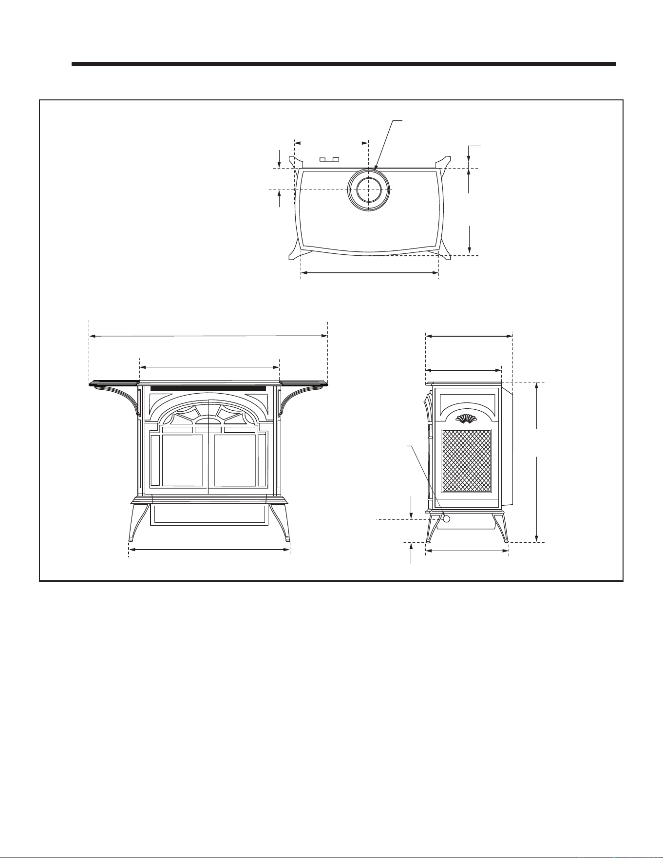
A. Appliance Dimension Diagram
2 2
Framing and Clearances
Figure 2.1 - Stardance dimensions. Weight: Fully assembled; 202 lbs.
Stove Dimensions
26-3/4"
(680 mm)
25-1/2"
(648 mm)
14-1/2"
(355 mm)
3"
(76 mm)
C
L
Supply Inlet
7" Outer Dia.
(178 mm)
Flue Collar
L
C
2-7/8”
(73 mm)
12-5/8”
(321 mm)
14-3/4”
(375 mm)
2-1/4”
(57 mm)
17”
(432 mm)
25-1/2”
(648 mm)
14”
(356 mm)
27”
(686 mm)
37-3/4”
(972 mm)
Disclaimer
The dimensions included are for planning, layout and design purposes only. Final holes for the venting system and any
other permanent modications to the dwelling must only be completed with the unit in the nal installed position.
66 3-90-30007467Vermont Castings • Stardance SDDVT Installation Manual_R40 • 09/25
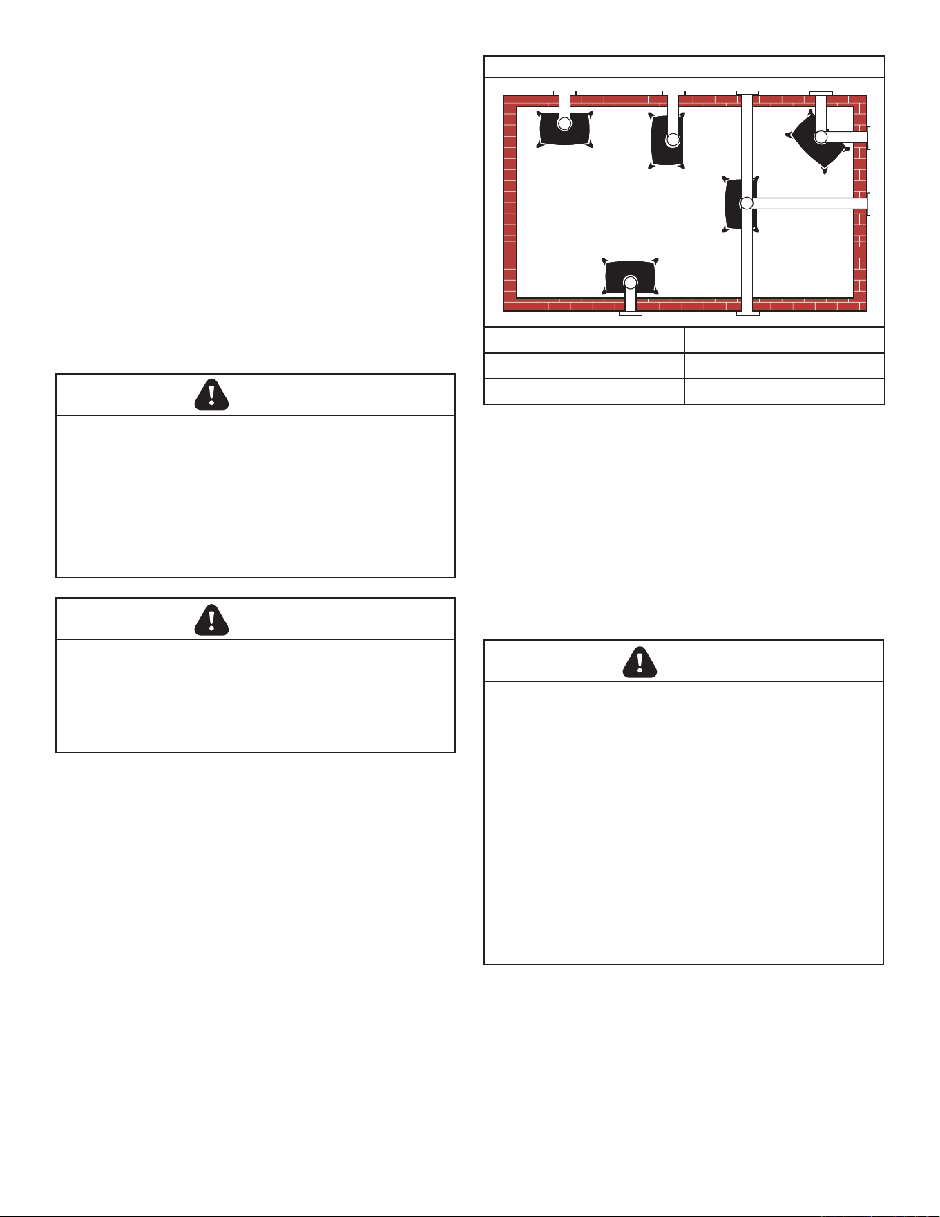
B. Installation Requirements
The installation must conform with local codes or, in the
absence of local codes, with the National Fuel Gas Code,
ANSI Z223.1/NFPA 54 - latest edition. (EXCEPTION: Do
not derate this appliance for altitude. Maintain the manifold
pressure at 3.5" w.c. for Natural Gas, and 10" w.c. for
Propane).
In Canada, installation must be in accordance with the current
CSA B-149.1 Installation Codes and/or local codes.
The installation should be done by a qualied service person
who is familiar with the building codes and installation
techniques appropriate for your area to accomplish a safe
and eective installation.
Your dealer or your local gas supplier will be able to refer a
qualied service person.
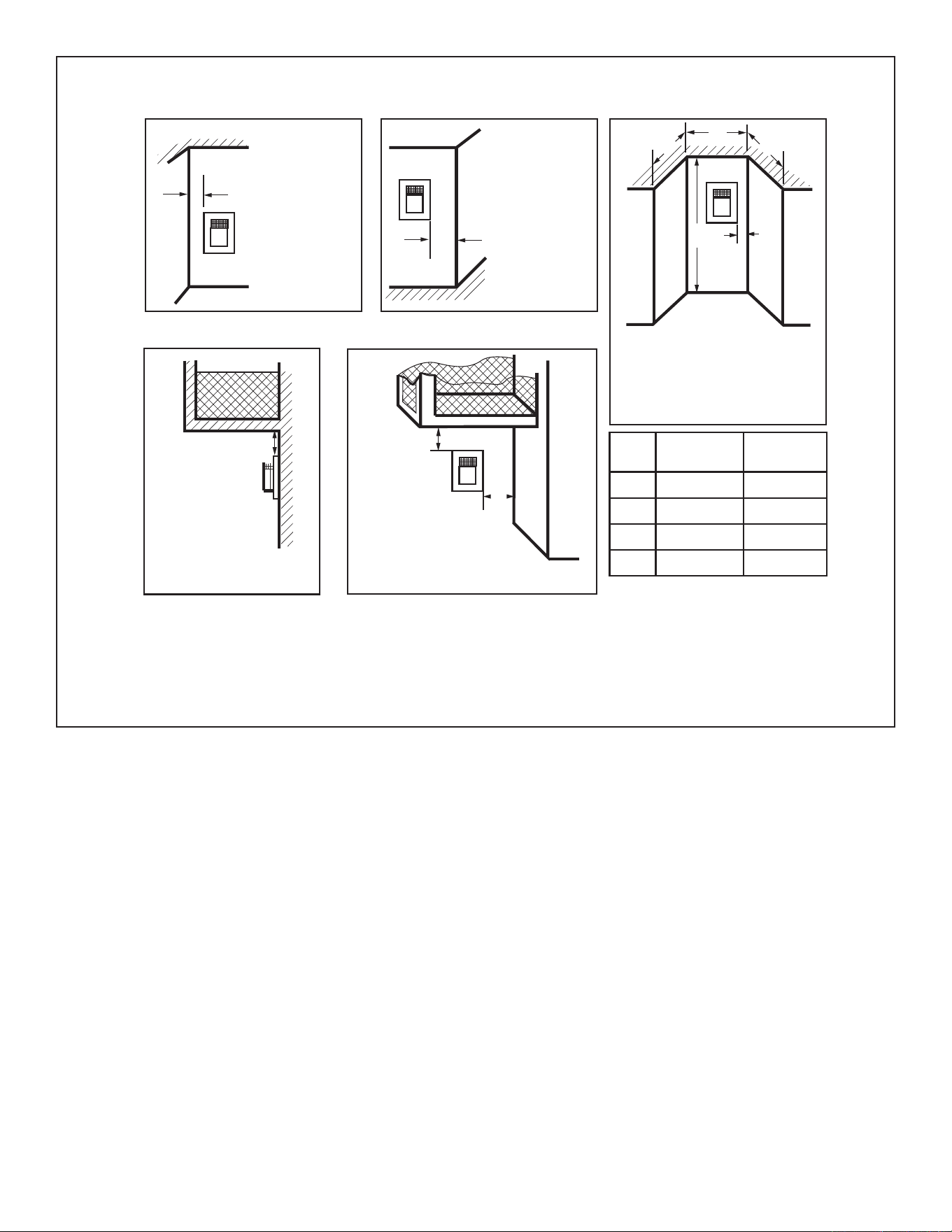
Figure 2.2 - Possible stove locations.
Direct Vent System Only
A. Flat on corner wall D. Cross Corner
B. Room Divider E. Flat on wall
C. Island
A
B
E
C
D
ST207a
Stardance
Stove locations
9/28/00 djt
C. Clearance Requirements
MinimumClearancestoCombustibleMaterials
Measure side clearances as shown in Figures 2.3 thru 2.6
from the outer edge of the cast iron stove top. Measure rear
clearances from the outermost surface of the steel rear skirt.
The Stardance heater is approved for installation into
an alcove constructed of combustible materials to the
dimensions and clearances shown in Figure 2.6.
The same clearances apply in a standard parallel installation.
In choosing a location for the stove, consider:
• The location of outside walls;
• Where additional heat is needed:
• Where family members gather most often;
• The vent system requirements.
NOTE: We do not recommend the use of wallpaper next to
this stove. Over time, radiant heat may cause the wallpaper
to shrink, or may adversely aect the binders in the wallpaper
adhesive.
WARNING
Due to high temperatures, the heater should be located
out of trac and away from furniture and draperies.
The surface of the Heater Is hot when it is in use. Young
children should be watched carefully when they are in the
same room when the Heater is in use, and they should
be taught to avoid the hot surface. Keep any objects that
can burn well away from the Heater, and observe the
recommended clearances that follow.
Improper installation, adjustment, alteration, service
or maintenance can cause injury or property damage.
Refer to this manual. For assistance or additional
information consult a qualified installer, service
agency or the gas supplier.
WARNING
This appliance may be installedin an aftermarket,*
permanentlylocated,manufacturedhome(USAonly)
ormobilehome,wherenotprohibitedbylocalcodes.
This appliance is for use only with the type of gas
indicated on the rating plate. This appliance is not
convertibleforusewithothergases,unlessacertied
kit is used.
* Aftermarket: Completion of sale, not for purpose of
resale, from the manufacturer.
WARNING
• Always maintain required clearances (air spaces) to
nearby combustibles to prevent re hazard. Do not
ll air spaces with insulation. Horizontal sections of
this vent system require a minimum of 3” (76 mm)
clearances to combustibles at the top of the ue
and 1” (25 mm) clearance at the sides and bottom
until the ue penetrates the outside wall. The gas
appliance and vent system must be vented directly to
the outside of the building and never be attached to a
chimney serving a separate solid fuel or gas-burning
appliance.
• Refer to the manufacturer’s instructions included
with the venting system for complete installation
procedures.
77 3-90-30007467Vermont Castings • Stardance SDDVT Installation Manual_R40 • 09/25
Wall Centerline from Floor
Direct Vent Only
A
Eective Minimum Centerline
56" (1480 mm)
(HHT Pipe)
52” (1378 mm)
(DuraVent Pipe)
ST131b
Stardance
wall thimble
01/19
A
Figure 2.5 - Minimum wall centerline.
D. Hearth Requirements
WALL AND CEILING CLEARANCES
Direct Vent Only
A: Rear Wall 4” (102 mm)
B: Min. Clearance 45-1/4” (1154 mm)*
C: Min. Alcove Height 72” (1830 mm)*
D: Max. Alcove Depth 48” (1220 mm)
Sidewall Clearance 4” (102 mm)
*Needed for installing DuraVent Minimum Vent Kit #2792 or HHT Minimum
Vent Kit #SLP-FSSK.
A
C
D
ST101b
Stardance
Direct Vent
Min. Clrnc
01/19
B
Figure 2.6 - Dimensions and clearances to ceiling or alcove.
The Stardance Heater can be installed on any type of rigid
ooring (e.g. hardwood, ceramic tile, brick, etc). When the
heater is installed on a carpeted surface, a metal or wooden
panel extending the full width and depth of the unit must be
used as the hearth. The purpose of the hearth is to prevent
the unit from sinking into the carpet surface and reducing
the required clearance to the underside of the unit. There
are no other hearth requirements.
E.ClearancestoCombustibles
CAUTION
Hearth and Home Technologies does not recommend adhesive
based vinyl ooring due to thermal expansion. Floating-style
ooring (LVP - luxury vinyl plank or LVT – luxury vinyl tile) can be
used, but it will reach temperatures up to 110 °F in a room with
ambient temperature of 70 °F. Consult ooring specications to
ensure compatibility.
HHT recommends gas stoves have 6 inches of alternative
ooring in front of the stove before using LVP/LVT regardless
if they sit ush on the oor or are elevated on a raised hearth.
For all other ooring, continue to follow clearance to combustible
requirements in the installation manual.
NOTICE: Clearances that do not meet the minimum guidelines
could result in damage or buckling to the vinyl ooring and is
done at the installer’s or homeowner’s risk.
Figure 2.4 - Corner installation, minimum corner clearances.
ST129b
Stardance
corner specs
01/19
4" (102 mm)
4" (102 mm)
Corner Installation Minimum Clearance
Figure 2.3 - Parallel installation, minimum back and side clearances.
ST128b
Stardance
flue centerline
01/19
*4" (102 mm)
4" (102 mm)
*Measurement from rear skirt.
Parallel Installation Minimum Clearance
88 3-90-30007467Vermont Castings • Stardance SDDVT Installation Manual_R40 • 09/25
The installation of your Vermont Castings stove must
conformwithlocalcodes,orintheabsenceoflocal
codes,withtheNationalFuelGasCodeANSIZ223.1/
NFPA 54 - latest edition, or CSA B149.1 Installation
code. (EXCEPTION: Do not derate this appliance
foraltitudeupto2,000(610m)fornaturalgasand
4,500feet(1,370m)forLPGas.Maintainthemanifold
pressure at 3.5" w.c. for Natural Gas and 10.0" w.c.
for LP Gas.
HIGH ELEVATIONS
Input ratings are shown in BTU per hour and are
certiedwithoutderationforelevationsupto2,000
feet(610m)fornaturalgasand4,500feet(1,370m)
forLPgasabovesealevel.
IntheUSAinstallationswithelevationsabove2,000
feet(610m)fornaturalgasand4,500feet(1,370m)for
LPgasmustbeinaccordancewiththecurrentANSI
Z223.1/NFPA54and/orlocalcodeshavingjurisdiction.
In Canada, please consult provincial and/or local
authorities having jurisdiction for installations at
elevations above 2,000 feet (610 m) for natural gas
and4,500feet(1,370m)forLPgas.
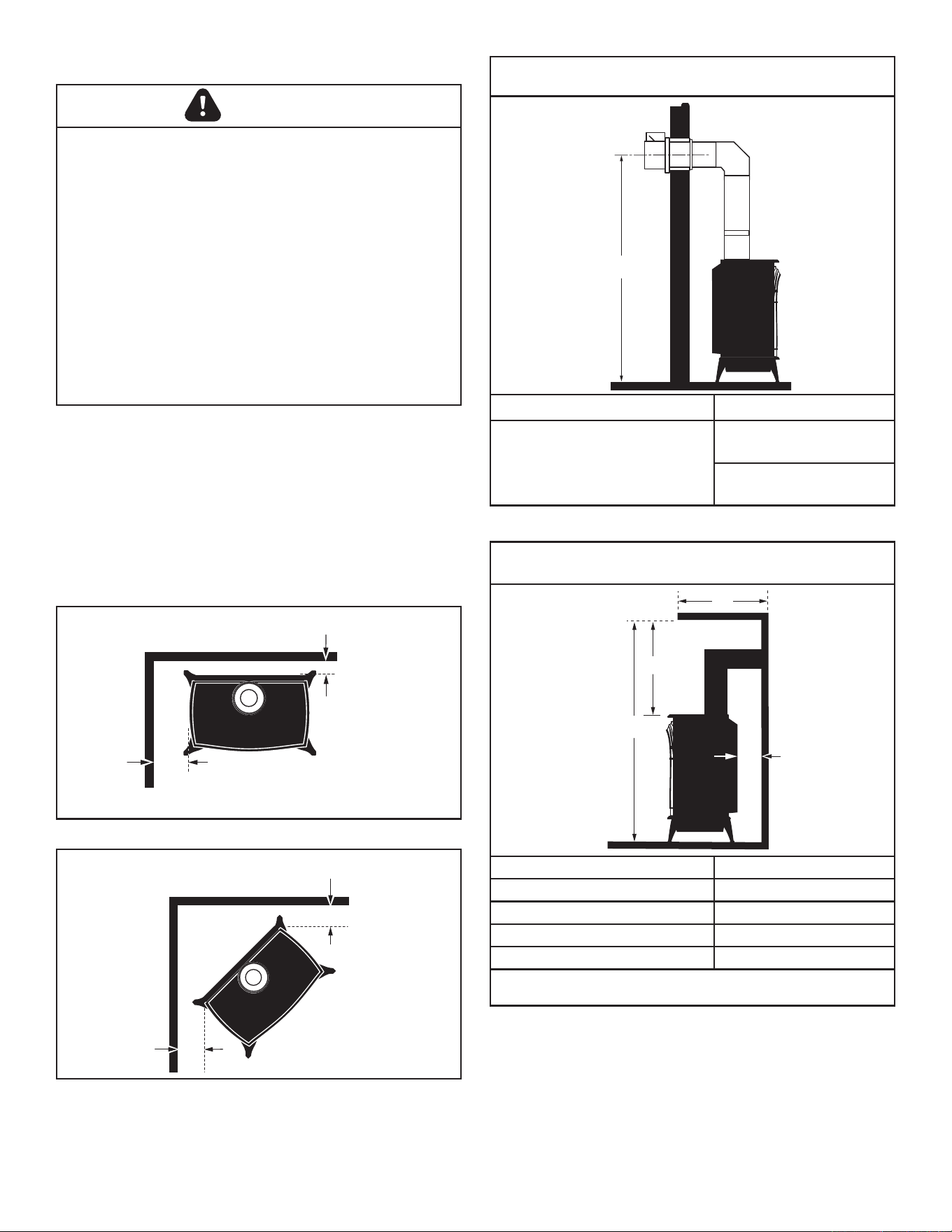
Horizontal Termination
The vent must rise vertically a minimum of 24" (610 mm) o
the top of the unit, before the rst elbow. The horizontal run
may extend up to 20’ (6m) and include a vertical rise of up to
40’ (12 m). (Figure 7) Horizontal termination must also meet
the criteria shown in Figures 2.11 through 2.12.
• Approved vent systems must terminate above and
including the heavy line in Figure 2.7.
• Two 45° elbows may be substituted for each single 90°
elbow.
• With a rise between 2’ - 5’, one 90° or two 45° elbows
may be used.
Figure 2.7 - Horizontal vent termination window.
Model Fuel Control
Max.
Input
BTU/h
Min. Input
BTU/h
SDDVT Nat.
Millivolt
Manual
28,000 20,000
SDDVT LP
Millivolt
Manual
25,000 21,000
SDVT-IFT Nat. IFT 28,000 20,000
SDVT-IFT LP IFT 25,000 21,000
WARNING
Improper installation, adjustment, alteration, service or
maintenance can cause injury or property damage. Refer
to this manual for correct installation and operational pro-
cedures. For assistance or additional information consult
a qualied installer, service agency, or the gas supplier.
F.GasSpecications G. Vent Terminations & Clearances
20
19
18
16
15
14
13
12
11
10
9
8
7
6
5
4
3
2
1
0
1 2 3 4 5 6 7 8 9 10 11 12 13 14 15 16 17 18 19 20
Vertical Run (in feet)
(Measured from the appliance flue collar to the top of the vent pipe.)
Horizontal Run (in feet)
21
22
23
24
25
26
27
28
29
30
31
32
33
34
35
36
37
38
39
40
ST134b
Radiance
Horizontal
vent run
6/07
May use up to
three 90° Elbows
One 90°
Elbow
Unacceptable
Venting Conguration
No Restrictor Plate
Required
Gas Inlet and Manifold Pressures
Natural Liquid Propane
Inlet Minimum 5.0" w.c. 11.0" w.c.
Inlet Maximum 14.0" w.c. 14.0" w.c.
Manifold Pressure 3.5" w.c. 10.0" w.c.
Air Shutter Setting 1/2" open 1/2” open
99 3-90-30007467Vermont Castings • Stardance SDDVT Installation Manual_R40 • 09/25
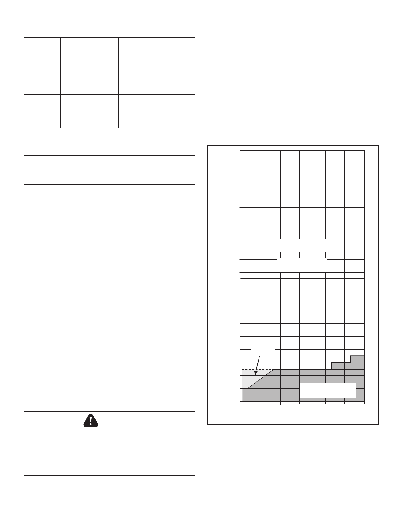
Vertical Termination
A vertical vent system must terminate no less than 8’ (2.44 m)
and no more than 40’ (12 m) above the appliance ue collar.
A restrictor plate (supplied) must be used, where specied,
in all vertically terminated vent systems. (Refer to Figure
2.8) NOTE: The restrictor plate supplied with the vertical
termination should be discarded. Adjust the restrictor plate
according to recommendations in Figure 2.10. A vertically
terminated vent system must also conform to the following
criteria:
• No more than three 90° elbows may be used.
• Two 45° elbows may be substituted for one 90° elbow.
No more than six 45° elbows may be used.
• Vent must rise a minimum of 2 feet (305 mm) before
oset is used.
• Termination height must conform to roof clearance as
specied in Figure 2.11.
Restrictor Plate Adjustment for Extended Pipe Runs
Adjustments can be made by loosening the adjustment screw
to allow the restrictor plate to slide up or down, Figure 2.9. A
guide for usage is shown in Figure 2.10.
NOTE: Some installations may require some adjustment by
the installer for optimum ame appearance. Optimum ame
appearance is a ame that is not subject to tall, dirty yellow
ames producing soot or ames lifting o of the ember bed
ports.
Restrictor Plate Adjustment
• Adjust plate (Figure 2.9) to location according to
guidelines in Figure 2.10.
• Tighten attachment screw.
• Install logs following log installation instructions.
Figure 2.8 - Vertical vent termination window.
20
19
18
16
15
14
13
12
11
10
9
8
7
6
5
4
3
2
1
0
20
1 2 3 4 5 6 7 8 9 10 11 12 13 14 15 16 17 18 19
Vertical Run (in feet)
(Measure from the appliance flue collar to the top of the vent pipe.)
Horizontal Run (in feet)
21
22
23
24
25
26
27
28
29
30
31
32
33
34
35
36
37
38
39
40
ST132a
FDV28
Vertical
vent run
12/3/99 djt
**
Unacceptable
Venting Conguration
**No Restrictor Plate
All Vertical
Terminations in this
area Require use
of the Restrictor
Plate*
Vertical terminations
must be within this
area
Figure 2.10
FireboxRestrictorSettings
20’-27’ 28’-35’ 35’-40’
Restictor Settings 1 2 3
Note: Numbering system starts with 1 on the bottom
ST917
restrictor plate
09/22
Figure 2.9 - Loosen screw to adjust restrictor plate.
Adjustment

1010 3-90-30007467Vermont Castings • Stardance SDDVT Installation Manual_R40 • 09/25
Your stove is approved to be vented either through the side
wall, or vertical through the roof.
• HHT does not require any opening for inspection of vent
pipe.
• Only HHT SLP venting components or DuraVent venting
components specically approved and labeled for this
stove may be used.
• Maintain minimum clearances between vent pipes and
combustible materials.
• Venting terminals shall not be recessed into a wall or
siding.
• Any horizontal run must have a 1/4” rise for every one (1)
foot of run towards the vent termination. Never run the
vent level or down.
There must not be any obstruction such as bushes, garden
sheds, fences, decks or utility buildings within 24" from the
front of the termination hood.
Do not locate termination hood where excessive snow or ice
build up may occur. Be sure to check vent termination area
after snow falls, and clear to prevent accidental blockage of
venting system. When using snow blowers, make sure snow
is not directed towards vent termination area.
Location of Vent Termination
It is imperative the vent termination be located observing the
minimum clearances as shown in this manual.
Vent Termination Clearances
When planning the installation, consider the location of the
vent terminal and clearances. Some of the most common
clearances to keep in mind are shown in Figure 2.11.
Important:All vent clearances must be maintained.
Check your vent termination clearances against Figures
2.11 and 2.12.
The vent should be placed so that people cannot be burned
by accidentally touching the vent surfaces when the stove
is operating.
The vent termination should be located where it cannot be
damaged by such things as automobile doors, lawn mowers
or snowblowers and it should be located away from areas
where it could become blocked by snow, etc.
Some considerations are:
• Obstructions or impediments to venting.
• Nearby combustible materials that could come into
contact with combustion exhaust gases.
• Other nearby openings {within 12" (305 mm)} through
which exhaust gas could reenter the building.
• All vegetation within 3’ (76 mm) that may interfere with
the draft.
Other factors that inuence where the installation will be
sited include the location of outside walls, where additional
heat may be desired in the home, where the family members
gather most regularly, and perhaps most importantly, the
distance limitations of the venting system.
IMPORTANT
The horizontal termination must not be recessed into
the exterior wall or siding.
Horizontal vent runs must be level toward the vent
termination.
Clearances around the vent termination must be
maintained.
For installations using DuraVent pipe, parallel installations
with minimum wall clearance have restricted access for
connecting the Horizontal Vent Cap straps to the vent
pipe. See the maker’s instructions for recommended
installation procedures.
1111 3-90-30007467Vermont Castings • Stardance SDDVT Installation Manual_R40 • 09/25
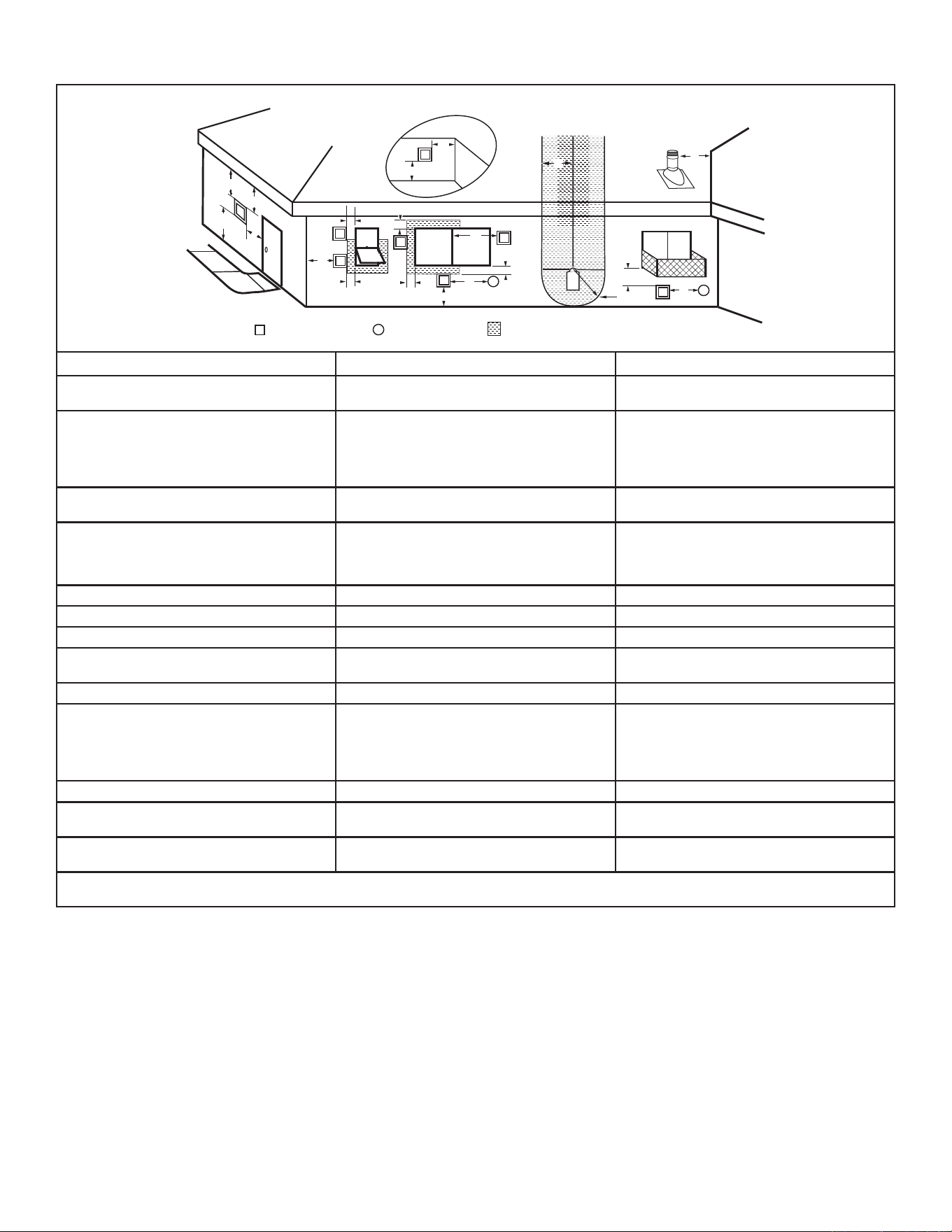
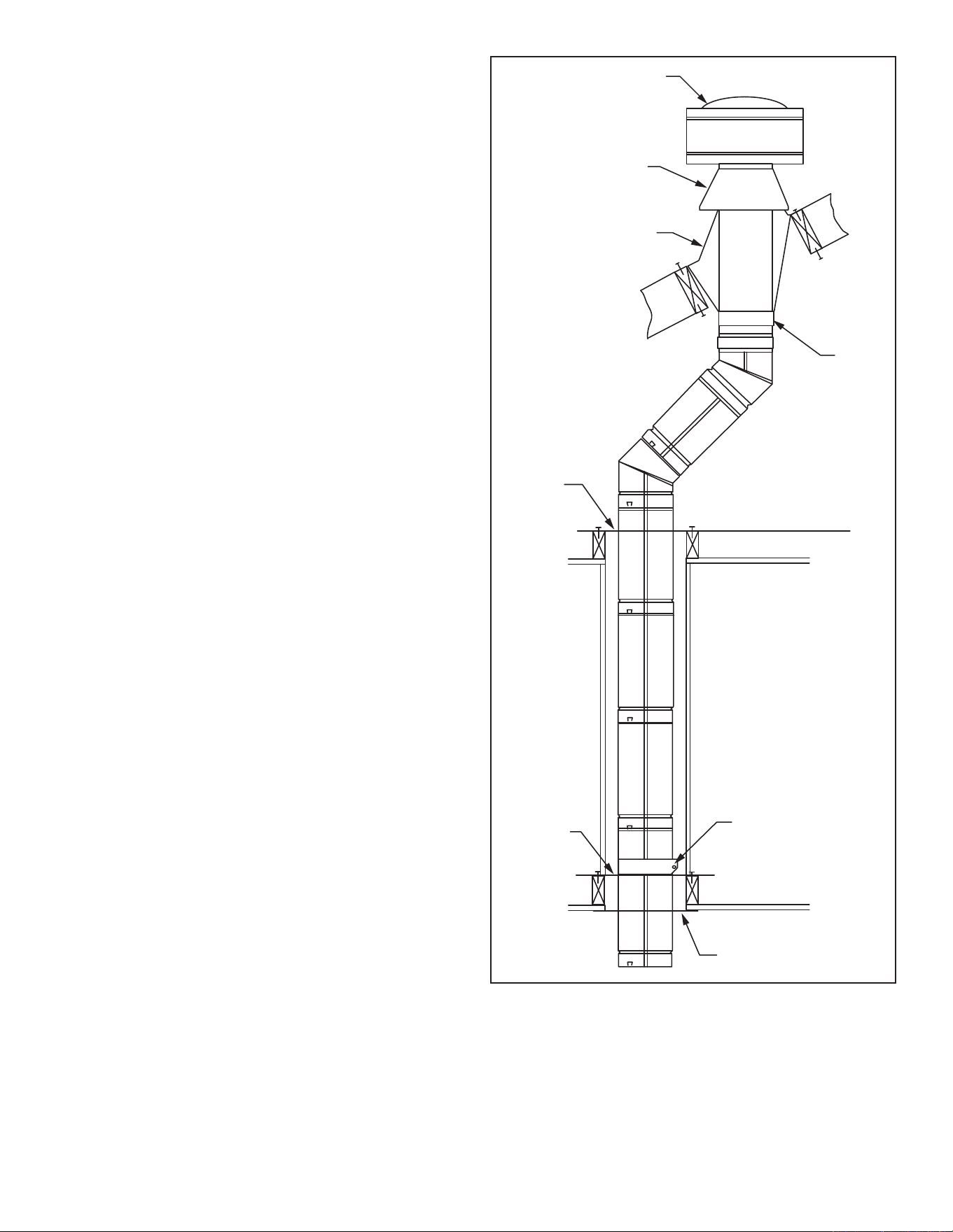
H. Chimney Diagram
CANADIAN INSTALLATIONS
1
US INSTALLATIONS
2
A = Clearance above grade, veranda, porch, deck
or balcony
12" (30cm) 12" (30cm)
B = Clearance to window or door that may be
opened
6" (15cm) for appliances <10,000 BTU/h (3kW)
12" (30cm) for appliances >10,000 BTU/h (3kW)
and <100,000 BTU/h (30kW)
36" (91cm) for appliances >100,000 BTU/h (30kW)
6" (15cm) for appliances <10,000 BTU/h (3kW)
9" (23cm) for appliances >10,000 BTU/h (3kW) and
<50,000 BTU/h (15kW)
12" (30cm) for appliances >50,000 BTU/h (15kW)
C = Clearance to permanently closed window 12" (305mm) recommended to prevent window
condensation
12" (305mm) recommended to prevent window
condensation
D = Vertical clearance to ventilated sot located
above the terminal within a horizontal distance
of 2' (610 mm) from the center line of the
terminal
18" (458mm) 18" (458mm)
E = Clearance to unventilated sot 12" (305mm) 12" (305mm)
F = Clearance to outside corner see next page see next page
G = Clearance to inside corner see next page see next page
H = Clearance to each inside of center line
extended above meter/regulator assembly
3' (91cm) within a height of 15' (5m) above the
meter/regulator assembly
3' (91cm) within a height of 15' (5m) above the
meter/regulator assembly
I = Clearance to service regulator vent outlet 3' (91cm) 3' (91cm)
J = Clearance to non-mechanical air supply inlet
to building or the combustion air inlet to any
other appliance
6" (15cm) for appliances <10,000 BTU/h (3kW)
12" (30cm) for appliances >10,000 BTU/h (3kW)
and <100,000 BTU/h (30kW)
36" (91cm) for appliances >100,000 BTU/h (30kW)
6" (15cm) for appliances <10,000 BTU/h (3kW)
9" (23cm) for appliances >10,000 BTU/h (3kW) and
<50,000 BTU/h (15kW)
12" (30cm) for appliances >50,000 BTU/h (15kW)
K = Clearance to mechanical air supply inlet 6' (1.83m) 3' (91cm) above if within 10' (3m) horizontally
L = Clearance above paved sidewalk or paved
driveway located on public property
7' (2.13m)
†
7' (2.13m)
†
M = Clearance under veranda, porch, deck or
balcony
12" (30cm)
‡
12" (30cm)
‡
N = Clearance above a roof shall extend a minimum of 24” (610mm) above the highest point when it passes through the roof surface, and any other obstruction
within a horizontal distance of 18” (450mm).
V
X
X
X
D
E
B
B
B
C
B
M
B
A
J
K
F
L
VENT TERMINATION AIR SUPPLY INLET
AREA WHERE TERMINAL IS NOT PERMITTED
H
I
Fixed
Closed
Operable
Operable
Fixed
Closed
B
CFM145a
DV Termin Location
5/01/01 Rev. 12/05/01
sta
INSIDE
CORNER DETAIL
A
G
CFM145a
V
V
V
V
V
V
V
V
N
Figure 2.11 - Vent termination clearances.
NOTE:
1. Local codes or regulations may require dierent clearances.
2. The special venting system used on Direct Vent Fireplaces are
certied as part of the appliance, with clearances tested and
approved by the listing agency.
3. HHT assumes no responsibility for the improper performance
of the appliance when the venting system does not meet these
requirements.
1. In accordance with the current CSA-B149 Installation Codes
2. In accordance with the current ANSI Z223.1/NFPA 54 National
Fuel Gas Codes
† A vent shall not terminate directly above a sidewalk or paved
driveway which is located between two single family dwellings
and serves both dwellings
‡ Only permitted if veranda, porch, deck or balcony is fully open
on a minimum 2 sides beneath the oor.
1212 3-90-30007467Vermont Castings • Stardance SDDVT Installation Manual_R40 • 09/25
Outside Corner
Inside Corner
Termination Clearances
Termination clearances for buildings with combustible and noncombustible exteriors.
G =
Combustible
6" (152 mm)
Noncombustible
2" (51 mm)
F =
Combustible
6" (152 mm)
Noncombustible
2" (51 mm)
G
Balcony -
with no side wall
M =
Combustible &
Noncombustible
12" (305 mm)
M
Balcony -
with perpendicular side wall
M = 12" (305 mm)
P = 6” (152 mm)
M
F
Alcove Applications*
C
D
C
E
V
V
Combustible &
Noncombustible
E = Min. 2” (51 mm)
for non-vinyl sidewalls
Min. 12” (305 mm)
for vinyl sidewalls
O = 8’ (2.4 m) Min.
O
P
V
V
V
Figure 2.12 - Termination clearances.
D
Min.
= # of Termination caps x 3
C
Max.
= (2 / # termination caps) x D
Actual
*NOTE: Termination in an alcove space (spaces open only on one side and with an overhang) is permitted with the dimensions specied for vinyl or
non-vinyl siding and sots.
1. There must be a 3’ (914 mm) minimum between termination caps.
2. All mechanical air intakes within 10’ (1 m) of a termination cap must be a minimum of 3’ (914 mm) below the termination cap.
3. All gravity air intakes within 3’ (914 mm) of a termination cap must be a minimum of 1’ (305 mm) below the termination cap.
# of
Caps
D
Min.
C
Max.
1 3’ (914 mm) 2 X D
Actual
2 6’ (1.8 m) 1 X D
Actual
3 9’ (2.7 m) 2/3 X D
Actual
4 12’ (3.7 m) 1/2 X D
Actual
1313 3-90-30007467Vermont Castings • Stardance SDDVT Installation Manual_R40 • 09/25
SLP Horizontal Termination Kit (Termination
Cap, SLP24-BK, SLP6-BK, SLP6A-BK,
SLP90-BK, SLP-WT-BK & CCSLP)
SLP-SK-BK
Stove Adapter Kit (Includes 30' of 4" Flex,
adapters, wall thimble, masonry and ZC
ashing, 991DA Cap and Fasteners
LINK-STOVE
Trapezoid Termination Kit (3-1/8” - 4-3/4”) SLP-TRAP1
Trapezoid Termination Kit (5-1/4” - 9-1/4”) SLP-TRAP2
Rear Vent Termination Kit SLP-RVTK
Vertical Termination cap - High Wind
(includes storm collar)
SLP-TVHW
Decorative Wall Thimble Cover SLP-WT-BK
Decorative ceiling restop - black SLP-DCF-BK
Cathedral ceiling support - black SLP-CCS-BK
4" (100mm) pipe length - black SLP4-BK
6" (150mm) pipe length - black SLP6-BK
12" Pipe length-black SLP12-BK
24" Pipe length-black SLP24-BK
36" (915mm) pipe length - black SLP36-BK
48" Pipe length-black SLP48-BK
3" - 6" (75 - 150mm) telescoping pipe
extension - black
SLP6A-BK
3" - 12" telescoping pipe extension-black SLP12A-BK
45 degree elbow-black SLP45-BK
90 degree elbow-black SLP90-BK
Stardance, Stardance, Oxford SLP adapter CCSLP
Freestanding Draft Hood Adapter FSDHAGSLP
SL Snorkel Cap (Includes 1 pair of restops) SLK-SNKD
*CCSLP adapter is required when using HHT components.
A. Venting Requirements & Options
Approved Vent System Components
The Stardance Heater must be vented to the outdoors
through an adjacent exterior wall or through the roof. The
venting system must be comprised of the appropriate venting
components specied on this page. This product has been
approved for use with ICC, Duravent and SLC Pipe.
HHT Components
3 3
AssemblyandInstallation
B.AssemblingtheStove:
Tools Required
• Utility knife
• Metal drill bit: size 28 (.140"/3.5mm)
• Flat-blade screwdriver
• Power drill
• Reciprocating saw
• 9/16" wrench
• 1/2” Wrench
• 3/8” Wrench
• 7/16” Wrench
Parts Bag Contents:
• Three (3) Vent Screws
• Wood handle w/insert lifter (handle for operable door)
• Restrictor Plate
• 4" Starter pipe
• Wireless Remote
• Three (3) Hex-head bolts, 1/4"- 20 x 1/2"
• One (1) Tube of Vent Gasket Cement
• Four (4) CS, Hex Hd 3/8-16 x 1 Gr 2-Z
• Four (4) Washer, Fl 3/8-Z
• Owner’s Installation and Operating Manual
Unpack Stove
Using the 1/2” wrench remove the (4) lag bolts installed
through the shipping brackets and into the skid. Once the lag
bolts are removed, remove the shipping brackets from each
leg using a 3/8” wrench. These bolts can be discarded after
removal. Install the (4) leg levelers provided in the manual
bag using a 9/16” wrench as needed.
WARNING
Only the IFT appliance is equipped with a three-prong
(grounded) plug for your protection against shock hazard
and should be plugged directly into a properly grounded
three-prong receptacle. Do not cut or remove the ground-
ing prong from this plug.
Note: An adapter is not required when using HHT SLP vent
pipe on this unit. A gas tight seal will still be made between
the inner and outer pipe sections. Use a minimum of two
screws to secure the SLP pipe to the starter collar.
1414 3-90-30007467Vermont Castings • Stardance SDDVT Installation Manual_R40 • 09/25
C.VentingSystemAssembly
CAUTION
All HHT Direct Vent Stoves have been tested and
approved to ANSI/CSA Standards and will operate safely
when installed in accordance with this instruction manual.
Read all instructions before starting installation, then follow
these instructions carefully to maximize stove performance
and safety. Report damaged parts to your dealer.
Important Safety Information
The termination cap MUST be vented directly to the outside.
The termination kit MUST NEVER be connected to a chimney
ue(s) servicing a separate solid-fuel burning appliance or
any other appliances.
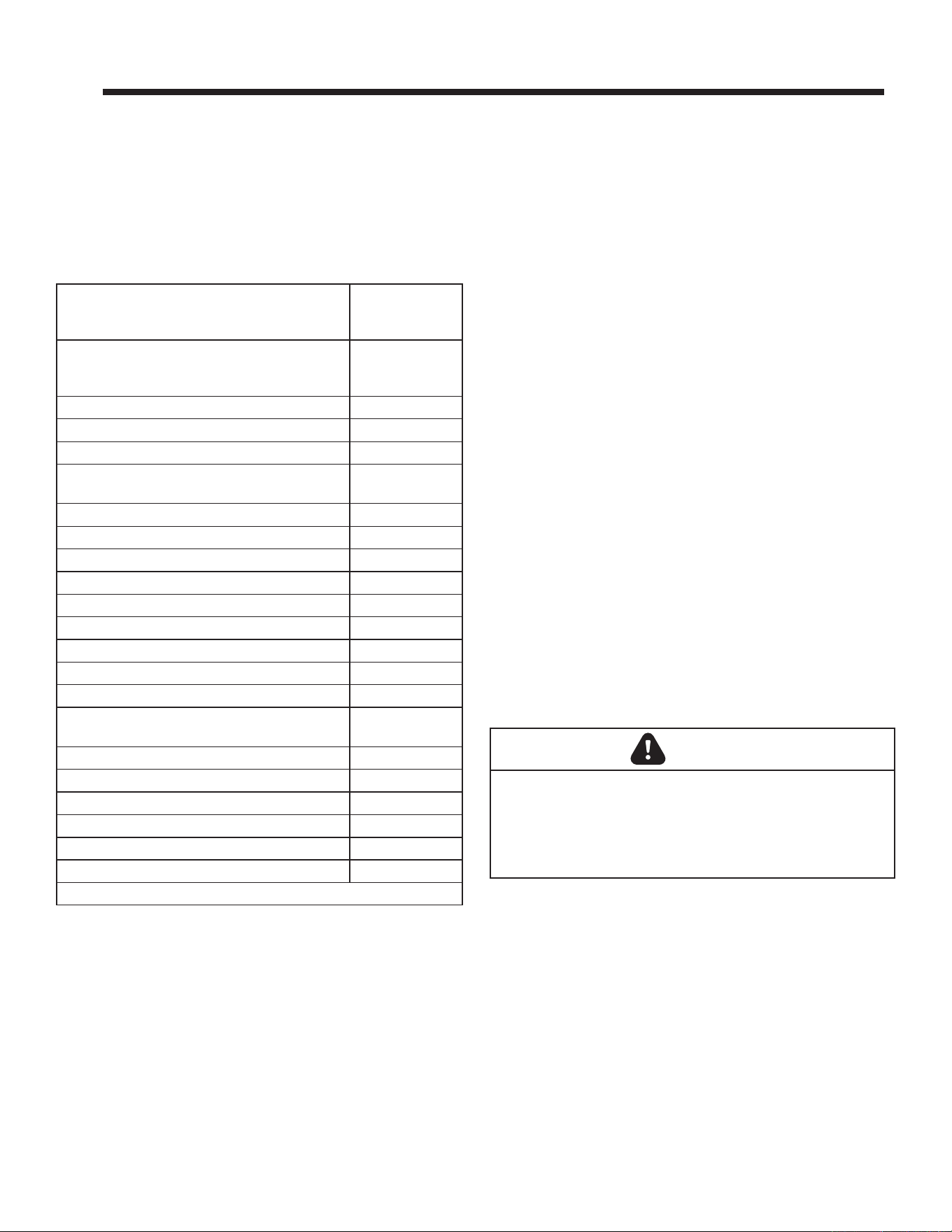
• Termination cap MUST NOT be recessed into a wall,
Figure 3.1.
• The installation must conform with local codes or in the
absence of local codes, with the National Fuel Gas Code,
ANSI Z223.1 (in the United States) or with the current
installation code CSA B149 (in Canada).
WARNING
Always maintain minimum clearances around vent
systems. Rear/Top Vent Vertical Side wall: Horizontal
sections of this vent system require a minimum of 3” (76
mm) clearances to combustibles at the top of the ue and
1” (25 mm) clearance at the sides and bottom until the ue
penetrates the outside wall. A minimum 1” clearance all
around the ue is acceptable at this point of penetration. If
vertical rise is 71⁄2 feet (2.3 m) or higher when top venting,
the clearance to combustibles is 1” on all sides of the
horizontal run. FOR VERTICAL RUNS ONLY, maintain a
1” (25 mm) minimum clearance to all sides. Do not pack
the open air spaces around the stove or ue with insulation
or other materials. Any horizontal run must have a 1/4” rise
for every one (1) foot of run towards the vent termination.
Never run the vent level or down.
WARNING
Failure to follow these instructions may create a possible
re hazard and will void the warranty.
WARNING
Any common venting of this gas appliance with other gas
appliances is not allowed.
Before You Start
Plan your installation. Set the stove in place and survey how
to best vent the unit. Select the appropriate termination kit
and vent pipe for the installation. Read these instructions
and the stove Owner’s Manual before beginning installation.
After vent conguration has been decided, begin attaching
pipe to unit.
Items required for installation:
Tools:
Hammer Saw and/or saber saw
Level Measuring Tape
Electric drill and bits Pliers
Square
Building Supplies:
Framing materials
Wall nishing materials
Caulking Material (noncombustible)
• These models are approved to use HHT direct vent
pipe components, HHT termination kits and DuraVent
components. No other venting system components may
be used.
• Horizontal runs must be supported every 3 feet (914 mm)
using wall straps. Vertical runs must be supported every
8 feet (2.4 m) using wall straps. Slip wall straps loosely
on to pipe. Attach straps to framing members using nails
or screws. Tighten nut/bolt to secure pipe.
• The stove and venting system should be inspected
before initial use and at least annually by a qualied
eld service person. Inspect the external vent cap on a
regular basis to make sure that no debris is interfering
with the airow. Inspect entire venting system to ensure
proper function.
Figure 3.1 - Termination cap on wall
Outside Wall
Finishing Material
(Vinyl Siding, etc.)
1515 3-90-30007467Vermont Castings • Stardance SDDVT Installation Manual_R40 • 09/25
General Information
The Stardance is approved for installation only with the vent
components listed under Section A “Venting Requirements
& Options”. Follow the vent component instructions exactly.
For U.S. installations: The venting system must conform with
local codes and/or the current National Fuel Gas Code, ANSI
Z223.1/NFPA 54.
For Canadian installations: The venting system must conform
to the current CSA B149.1 installation code.
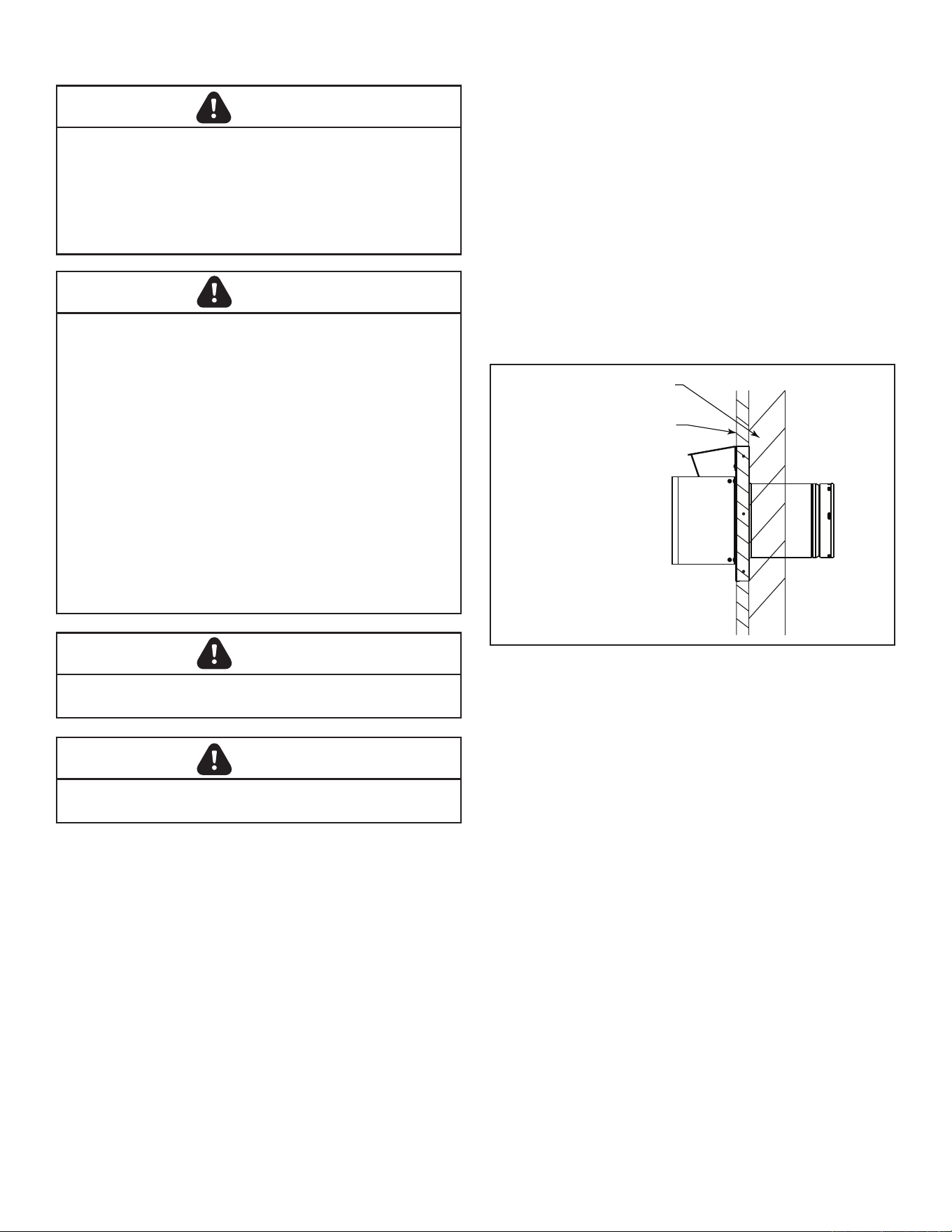
Install the starter Pipe
1. Attach the starter to the stove.
2. Place a 3/8” bead of sealant around the inside of the cast
starter collar. Stove cement is provided in the manual
bag for this purpose. Insert the 6-5/8” outer adapter into
the cast outer starting collar and press down rmly.
3. Install the CCSLP Outer Adapter Pipe.
4. Place a 3/8” bead of sealant around the 4” crimped
end of the starter collar on the stove. Stove cement is
provided in the manual bag for this purpose. Attach the
SLP pipe to the adapter, and secure by aligning adapter
and pipe seams, pressing down rmly until pipe stops,
and twisting to lock into place, Figure 3.2.
WARNING
Any horizontal run must have a 1/4” rise for every one (1)
foot of run towards the vent termination. Never allow the
vent pipe to run down. This could cause high temperatures
and may present a re hazard.
WARNING
Termination cap must be positioned so the embossed
arrow is pointed up.
Figure 3.2 - Attach inner assembly to ue collar.
ST647
attach inner assy
SLP
CCSLP
Starter
Pipe
AssembleSlipSections
The outer ue of the slip section should slide over the outer
ue of the pipe section and into (inner ue) the last pipe
section, Figure 3.4.
Slide together to the desired length, making sure that a 1-1/2”
outer ue overlap is maintained between the pipe section
and slip section.
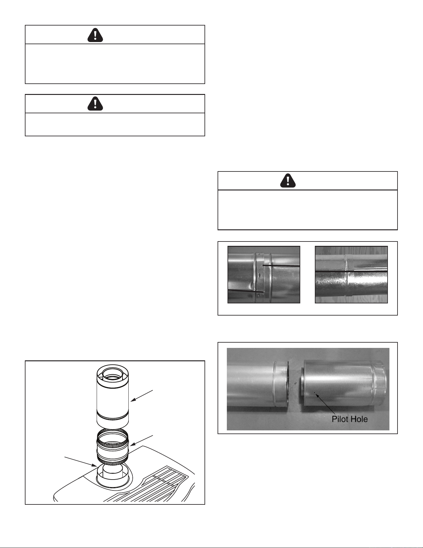
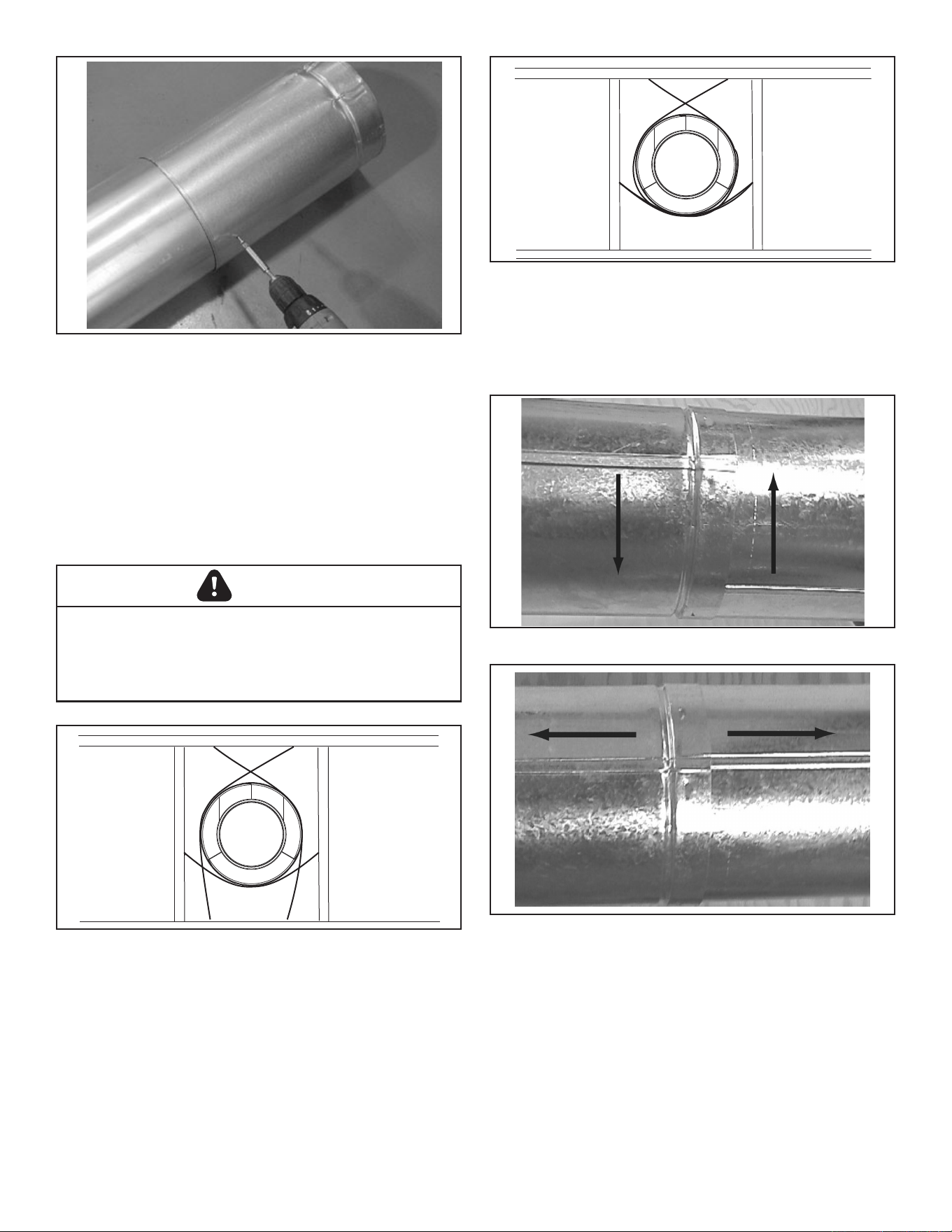
The pipe and slip section need to be secured by driving two
1/2 in. screws through the overlapping portions of the outer
ues using the pilot holes, Figure 3.5.
This will secure the slip section to the desired length and
prevent it from separating. The slip section can then be
attached to the next pipe section.
If the slip section is too long, the inner and outer ues of the
slip section can be cut to the desired length.
WARNING
Risk of Fire/Explosion! DO NOT break seals on slip
sections. Use care when removing termination cap from
slip pipe. If slip section seals are broken during removal
of the termination cap, vent may leak.
INCORRECTCORRECT
Figure 3.3 - Make sure the seams are not aligned to prevent
unintentional disconnection.
Figure 3.4 - Slip Section Pilot Holes
1616 3-90-30007467Vermont Castings • Stardance SDDVT Installation Manual_R40 • 09/25
Secure the Vent Sections
Vertical sections of SLP pipe must be supported every 8 feet.
The SLP restop includes tabs that may be used to secure
vertical sections.
The vent support or plumber’s strap (spaced 120° apart) may
be used to secure the vertical sections of pipe, Figure 3.6.
Horizontal sections of vent must be supported every 5 feet
with a vent support or plumber’s strap, Figure 3.7.
Figure 3.5 - Screws into Slip Section
WARNING
RiskofFire/Explosion/Asphyxiation! Improper support
may allow vent to sag and separate. Use vent run supports
and connect vent sections per installation instructions. DO
NOT allow vent to sag below connection point to appliance.
Figure 3.6 - Securing Vertical Pipe Sections
Figure 3.7 - Securing Horizontal Pipe Sections
DisassembleVentSections:
To disassemble any two pieces of pipe, rotate either section,
Figure 3.8, so that the seams on both pipe sections are
aligned, Figure 3.9. They can then be carefully pulled apart.
Figure 3.8 - Rotate Seams for Disassembly
Figure 3.9 - Align and Disassemble Vent Sections
1717 3-90-30007467Vermont Castings • Stardance SDDVT Installation Manual_R40 • 09/25
Horizontal Termination Cap:
WARNING
Risk of Fire! The telescoping flue section of the
termination cap MUST be used when connecting vent.
• 1-1/2” (38 mm) minimum overlap of vent and
telescoping ue section is required.
Failure to maintain overlap may cause overheating and
re.
Note:Forhorizontalventrunsthroughacombustible
wall and framing dimensions, refer to appliance
installation manual.
Install the Horizontal Termination Cap
Attach slip section of cap to last vent section. Maintain 1-1/2”
overlap between slip and vent sections.
Note: For installations using black pipe, slide the
decorativewall thimble over the last vent pipebefore
connecting the termination to the pipe. When this
connectionhasbeenmade,slidethewallthimbleupto
the interior wall surface and attach with screws provided.
Secure termination cap to exterior wall using provided holes
and fasteners.
Vent termination must not be recessed in the wall. Siding
may be brought to the edge of the cap base.
Flash and seal as appropriate for siding material at outside
edges of cap.
When installing a horizontal termination cap, follow the cap
location guidelines as prescribed by current ANSI Z223.1
and CAN/CGA-B149 installation codes.
CAUTION
Risk of Burns! Local codes may require installation of a
termination guard to prevent anything or anyone from
touching the hot cap.
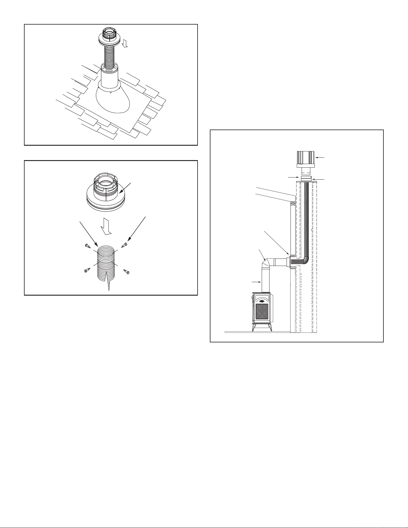
DivertRoofRun-o
HHT recommends, where excessive water run-o is possible,
use of one of the two options shown in Figure 3.10 to prevent
water running off the roof and onto/into the horizontal
termination cap.
Install gutter
Install L-shaped
diverter
Figure 3.10 - Locate vent opening on wall.
1818 3-90-30007467Vermont Castings • Stardance SDDVT Installation Manual_R40 • 09/25
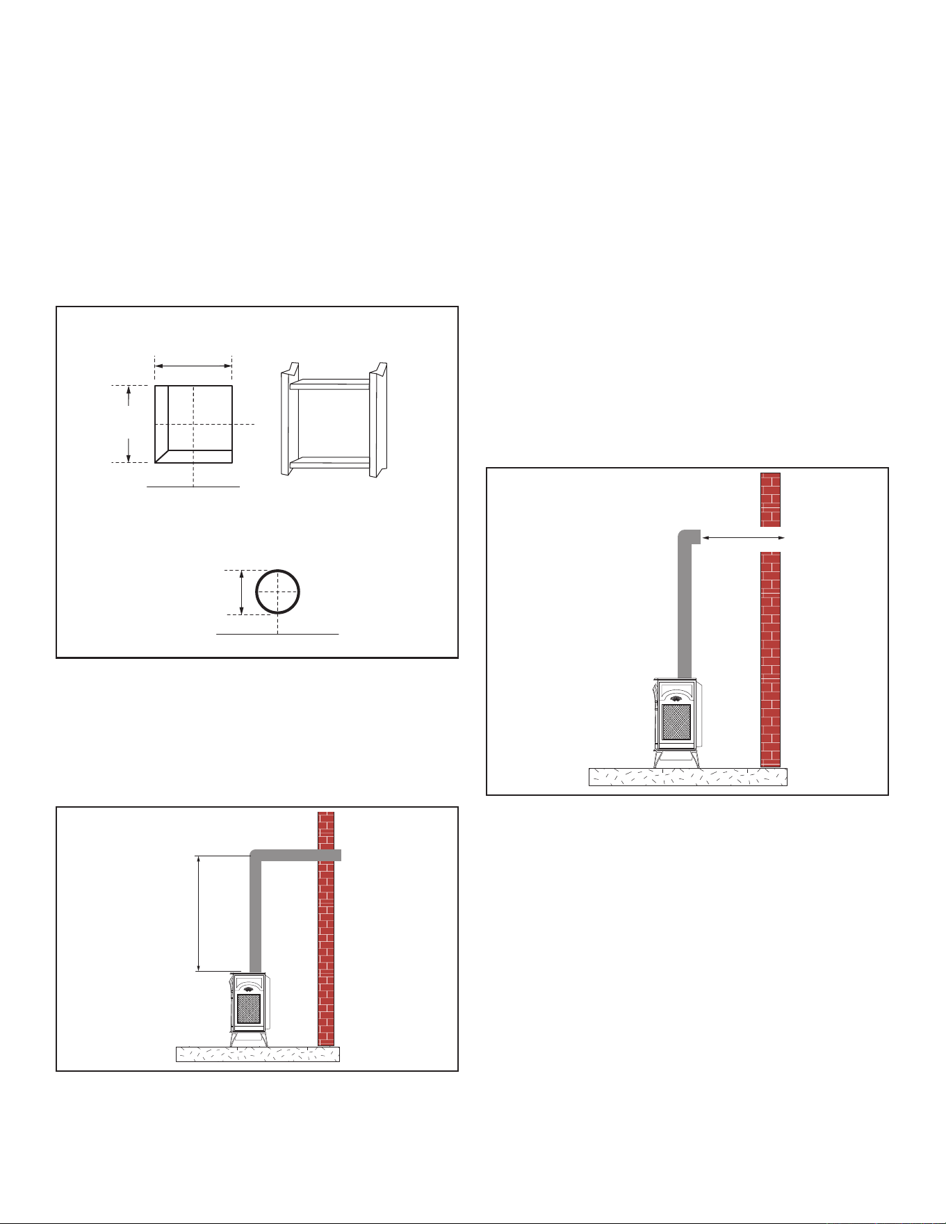
4. Using appropriate length of pipe section(s) attach to
stove by twisting collar.
5. Measure the horizontal length requirement including a 2”
(51 mm) overlap, i.e. from the elbow to the outside wall
face plus 2” (51 mm) (or the distance required if installing
a second 90° elbow), Figure 3.13.
NOTE: Always install vertical side wall horizontal venting
with a 1/4” rise for every 12” of run.
6. Use appropriate length of pipe sections – telescopic or
xed – and install. The sections which go through the
wall are packaged with the starter kit, and can be cut to
suit if necessary.
7. Guide the vent terminations 4” and 6-5/8” collars into their
respective vent pipes. Double check that the vent pipes
overlap the collars by 2” (51 mm). Secure the termination
to the wall with screws provided and caulk around the
wall plate to weatherproof. As an alternative to screwing
the termination directly to the wall, you may also use
expanding plugs or an approved exterior construction
adhesive.
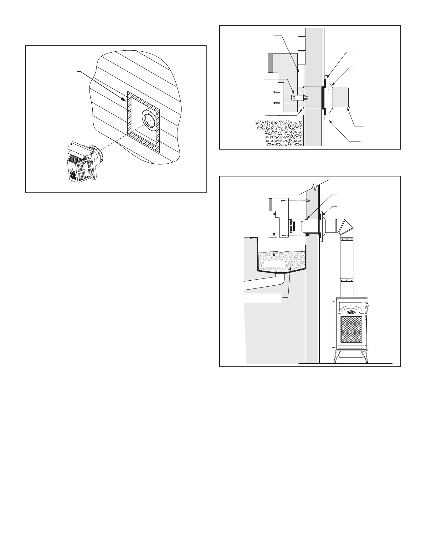
2. Secure restop to the inside frame, center in the 10" x 10"
vent opening.
3. Place stove into position. Measure the vertical height (X)
required from the base of the ue collars to the center of
the wall opening, Figure 3.12
Stove Hearth
VentOpeningforCombustibleWalls
VO584-100
Vent Opening
2/99 djt
Stove Hearth Framing Detail
OpeningforNoncombustibleWall
7"
(190 mm)
10"
(254 mm)
10"
(254 mm)
Figure 3.11 - Locate vent opening on wall.
X
Figure 3.12 - Vertical Height Requirements
VERTICAL SIDE WALL INSTALLATION:
NOTE: Refer to Figures 2.8 thru 2.10 for restrictor plate
adjustments for vertical vent runs.
1. Locate vent opening on the wall. It may be necessary
to rst position the stove and measure to obtain hole
location. Depending on whether the wall is combustible
or noncombustible, cut the opening to size, Figure
3.11 (for combustible walls rst frame in opening).
Combustible Walls: Cut a 10" x 10" (254 x 254 mm) hole
through the exterior wall and frame as shown, Figure 3.11.
Noncombustible Walls: Hole opening must be 7" (178
mm) in diameter.
X
Figure 3.13 - Horizontal Length Requirement
1919 3-90-30007467Vermont Castings • Stardance SDDVT Installation Manual_R40 • 09/25
NOTE:Supporthorizontalpipesevery5'(152cm)with
metal pipe straps.
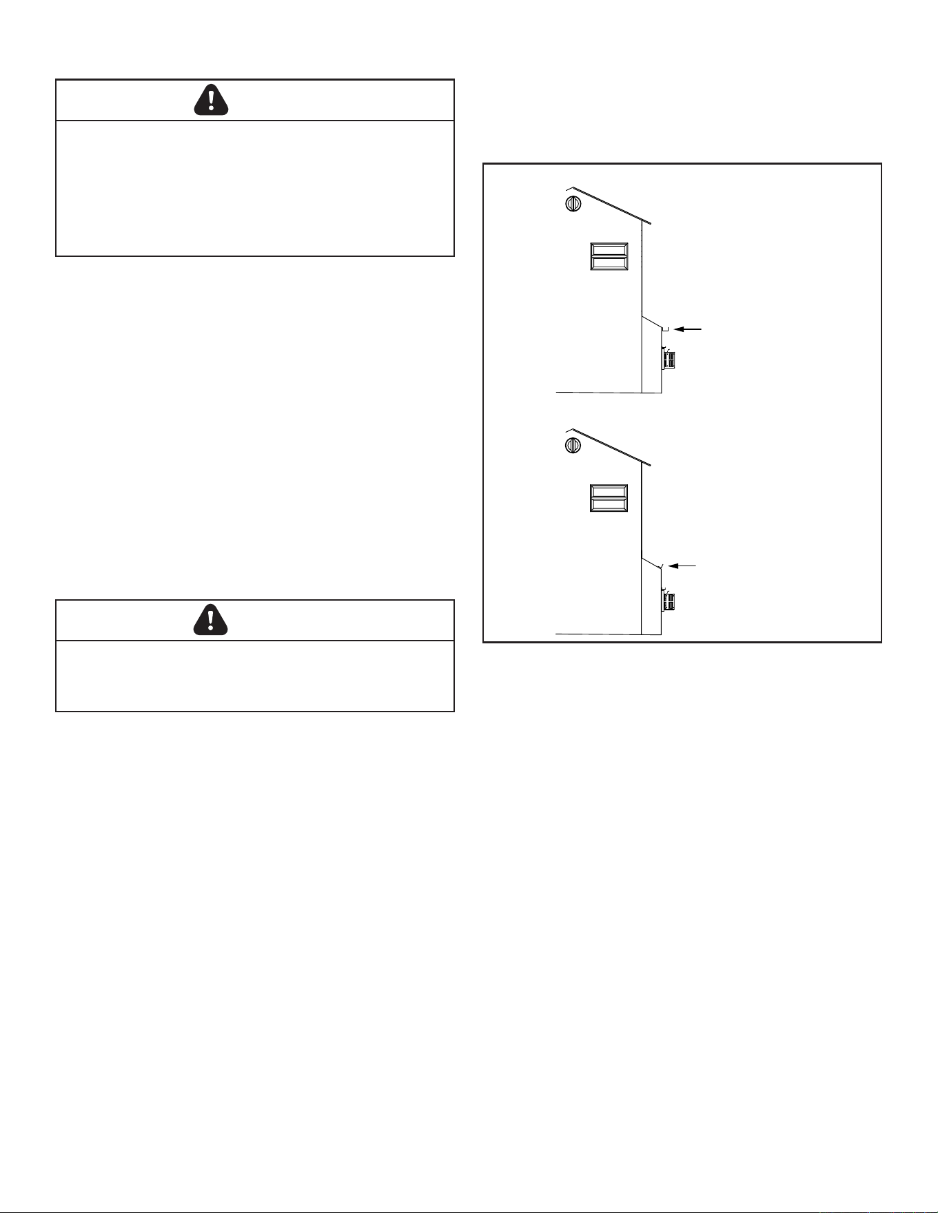
Vent Termination Below Grade:
Install Snorkel Kit #SLP-SNORK when it is not possible to
meet the required vent termination clearances of 12" (305
mm) above grade level. The snorkel kit will allow installation
depth of down to 7" (178 mm) below grade level. The seven
inches is measured from the center of the horizontal vent
pipe as it penetrates the wall. If the venting system is
installedbelowgrade,awindowwellmustbeinstalled
with adequate and proper drainage.
NOTE: Be sure to maintain side wall clearances and vent
run restrictions. Refer to Figures 2.3 thru 2.6.
1. Establish the vent hole through the wall.
2. Remove soil to a depth of approximately 16" (406 mm)
below the base of the snorkel. Install a window well (not
supplied). Rell the hole with 12" (305 mm) of coarse
gravel and maintain a clearance of at least 4" (102 mm)
below the snorkel, Figure 3.16.
3. Install the vent system as described in Figures 3.2 thru
3.9.
4. Be sure to make a watertight joint around the vent pipe
joint at the inside and outside wall joints.
5. Apply high temperature sealant around the inner and
outer snorkel collars. Join the pipes and fasten the
snorkel termination to the wall with the screws provided.
6. Level the soil to maintain a 4" clearance below the
snorkel.
7. If the foundation is recessed, use extension brackets
(not supplied) to fasten the lower portion of the snorkel.
Fasten the brackets to the wall rst, and then fasten to the
snorkel with self-tapping #8 x 1/2" sheet metal screws.
Extend the vent pipes out as far as the protruding wall
face, Figure 3.15.
SLP Cap
Cutout On Vinyl
Vinyl Siding Wall
Termination Cap
Figure 3.14 - Horizontal Termination Cap on a Vinyl Siding Wall
Figure 3.15 - Use extension brackets to mount snorkel against
recessed wall.
ST219
snorkel detail
12/6/99 djt
Recessed Wall
Sheet Metal
Screws and
Bracket
Wall Screws
and Anchors
Waterproof Seal
Around Pipe
Firestop
Finishing
Collar
7" Pipe
Wall Plate
ST653
install snorkel
04/19 ts
Waterproof Seal
Around Pipe
Firestop
Window Well
Drain
4" Clearance
Snorkel
Termination Cap
Wall Screws
and Anchors
Gravel
Figure 3.16 - Snorkel kit installation.
2020 3-90-30007467Vermont Castings • Stardance SDDVT Installation Manual_R40 • 09/25
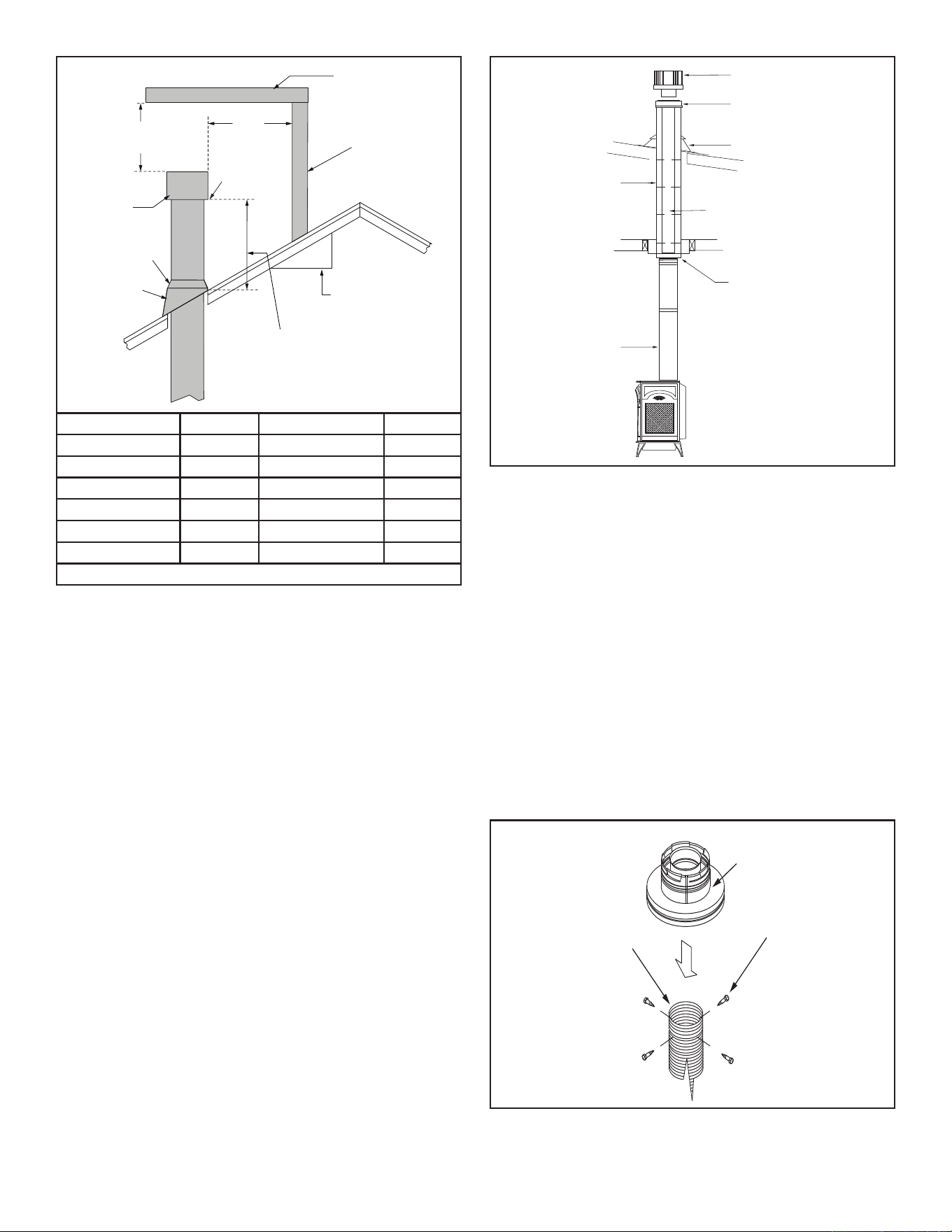
VerticalThrough-The-RoofApplication/Installation:
Note: Refer to Figures 2.8 thru 2.10 for restrictor plate
adjustments for vertical vent runs.
This gas stove has been approved for:
• Vertical installations up to 40 feet (12 m) in height. Up to
a 10 feet (3 m) horizontal vent run can be installed within
the vent system using a maximum of two 90° elbows,
Figure 3.17.
• Up to two 45° elbows may be used within the horizontal
run. For each 45° elbow used on the horizontal plane,
the maximum horizontal length must be reduced by 18"
(450 mm).
Example: Maximum horizontal length:
No elbows = 10' (3 m)
1 x 45° elbow = 8.5' (2.6 m)
2 x 45° elbows = 7' (2.1 m)
• A minimum of an 8 feet (2.5 m) vertical rise is required,
Figure 3.17.
• Two sets of 45° elbow osets may be used within the
vertical sections. From 0 to a maximum of 8 feet (2.5 m)
of vent pipe can be used between elbows, Figure 3.17.
• SLP-HVS supports osets. This application will require
that you rst determine the roof pitch and use the
appropriate starter kit. (Refer to Venting Components
list.)
• The maximum angular variation allowed in the system is
270°, Figure 3.18
• For the minimum height of the vent above the highest
point of penetration through the roof, Figure 3.18.
Figure 3.17 - Typical Vertical Venting Conguration
ST933
Selkirk vertical venting
6/07
Ceiling Support Collar
Ceiling
Support
Plate
Trim Plate
Firestop
Spacer
Oset
Support Collar
Flashing
Storm Collar
Vertical Termination
2121 3-90-30007467Vermont Castings • Stardance SDDVT Installation Manual_R40 • 09/25
Roof Pitch H(Min.)Ft. Roof Pitch H(Min.)Ft.
Flat to 6/12 1.0* Over 11/12 to 12/12 4.0
Over 6/12 to 7/12 1.25* Over 12/12 to 14/12 5.0
Over 7/12 to 8/12 1.5* Over 14/12 to 16/12 6.0
Over 8/12 to 9/12 2.0* Over 16/12 to 18/12 7.0
Over 9/12 to 10/12 2.5 Over 18/12 to 20/12 7.5
Over 10/12 to 11/12 3.25 Over 20/12 to 21/12 8.0
* 3 Feet. Minimum in Snow Regions
Horizontal
overhang
12
X
20 in.
(508 mm)
Lowest
Discharge
Opening
Termination
Cap
Roof Pitch
is X / 12
Vertical
wall
H (min.) - Minimum height
from roof to lowest
discharge opening.
24 in. min.
(610 mm)
Roof Pitch H (Min.) Ft. Roof Pitch H (Min.) Ft.
Flat to 6/12 1.0* Over 11/12 to 12/12 4.0
Over 6/12 to 7/12 1.25* Over 12/12 to 14/12 5.0
Over 7/12 to 8/12 1.5* Over 14/12 to 16/12 6.0
Over 8/12 to 9/12 2.0* Over 16/12 to 18/12 7.0
Over 9/12 to 10/12 2.5 Over 18/12 to 20/12 7.5
Over 10/12 to 11/12 3.25 Over 20/12 to 21/12 8.0
* 3 ft. minimum in snow regions
Storm Collar
Roof
Flashing
Figure 3.18 - Minimum Height from Roof to Lowest Discharge
Opening
Class A Metal Chimney
Prior to installing the gas stove, ensure that the existing
chimney is functionally sound and clean.
• Have the chimney and adjacent structure inspected
and cleaned by qualied professionals. Hearth & Home
Technologies recommends that NFI or CSIA certied
professionals, or technicians under the direction of
certied professionals, conduct a minimum of a NFPA
211 Level 2 inspection of the chimney.
• Replace component parts of the chimney and replace
as specied by the professionals.
1. Remove existing chimney cap.
2. Measure the distance from the top of the chimney to the
bottom of the ceiling support box, add 3 in. (76mm) to
this measurement, and cut a section of 4 in. (101mm)
flex pipe to that length (the flex should be fully extended).
3. Connect the end of the flex pipe section to the underside
of the top adapter, using four sheet metal screws. See
Figure 3.20.
4. Pass the flex pipe down through the center of the
chimney system, and center the top adapter on the top
of the chimney pipe. Drill four 1/8 in. (3mm) diameter
holes through the top adapter, and into the chimney
top. Ensure that you are drilling into the metal on the
chimney. Twist lock the high wind termination cap onto
the top adapter. See Figure 3.21 and Figure 3.22.
Top Adapter
(Included in Link-Stove Kit)
Sheet Metal Screws
4” Flex Pipe
(Included in Link-Stove Kit)
Figure 3.20
Termination Cap
(Includ. in Link-Stove Kit)
Existing Metal
Chimney System
Top Adaptor
(Includ. in Link-Stove Kit)
Direct Vent Pipe
(Length as required)
Flashing
(Includ. in Link-Stove Kit)
4 in. (102mm) Flex Pipe
(Includ. in Link-Stove Kit)
Retro Connector
(Includ. in Link-Stove Kit)
Figure 3.19
2222 3-90-30007467Vermont Castings • Stardance SDDVT Installation Manual_R40 • 09/25
Figure 3.21
5. Pull the flex pipe down through the ceiling support box,
until it protrudes approximately 3 in. (76mm). Connect
the flex pipe to the retro connector, and attach with sheet
metal screws.
6. Push the flex pipe back up into the ceiling support box,
center the retro connector, and attach it to the support
box with sheet metal screws.
7. The connection between the appliance and the retro
connector may be completed with sections of direct vent
pipe.
Top Adapter
(Included in Link-Stove Kit)
Sheet Metal Screws
4” Flex Pipe
(Included in Link-Stove Kit)
Figure 3.22
Up & Out Installation
Termination Cap
(Included in LINK-STOVE Kit)
Flashing
(Included in Masonry
Chimney Conversion Kit &
LINK-STOVE Kit)
4 in. (102mm) Flex Liner
(Included in LINK-STOVE Kit)
Top Adaptor
(Included in Masonry Chimney
Conversion Kit & LINK-STOVE Kit)
Retro Connector
(Included in Masonry Chimney
Conversion Kit & LINK-STOVE Kit)
90° Elbow
Direct Vent Pipe
(Length as required)
Figure 3.23
Existing Masonry Chimney
Prior to installing the gas stove, ensure that the existing
chimney is functionally sound and clean.
• Have the chimney and adjacent structure inspected and
cleaned by qualied professionals. Hearth & Home
Technologies recommends that NFI or CSIA certied
professionals, or technicians under the direction of
certied professionals, conduct a minimum of a NFPA
211 Level 2 inspection of the chimney.
• Replace component parts of the chimney and replaceas
specied by the professionals.
2323 3-90-30007467Vermont Castings • Stardance SDDVT Installation Manual_R40 • 09/25
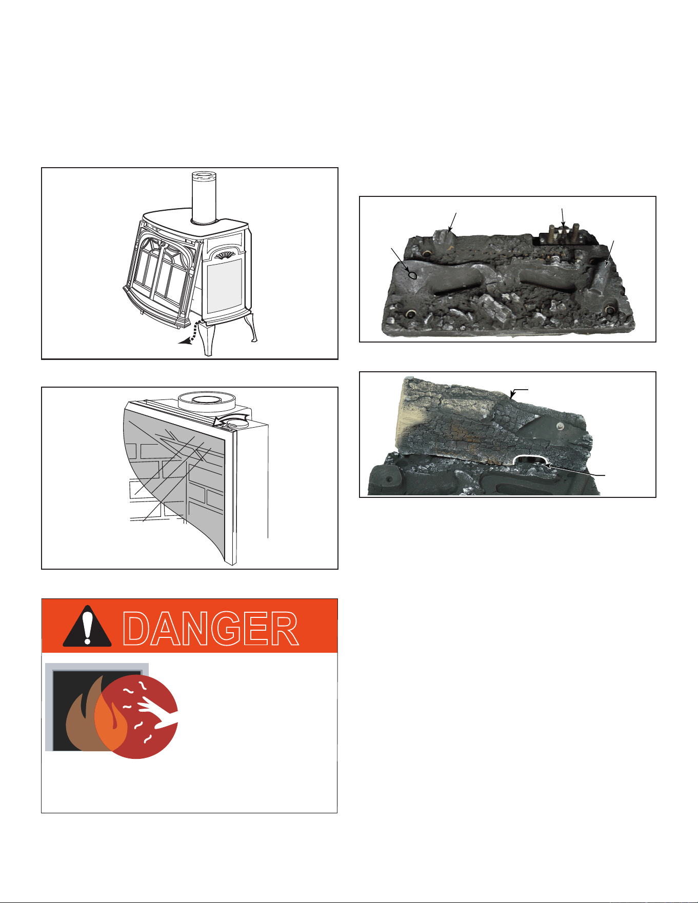
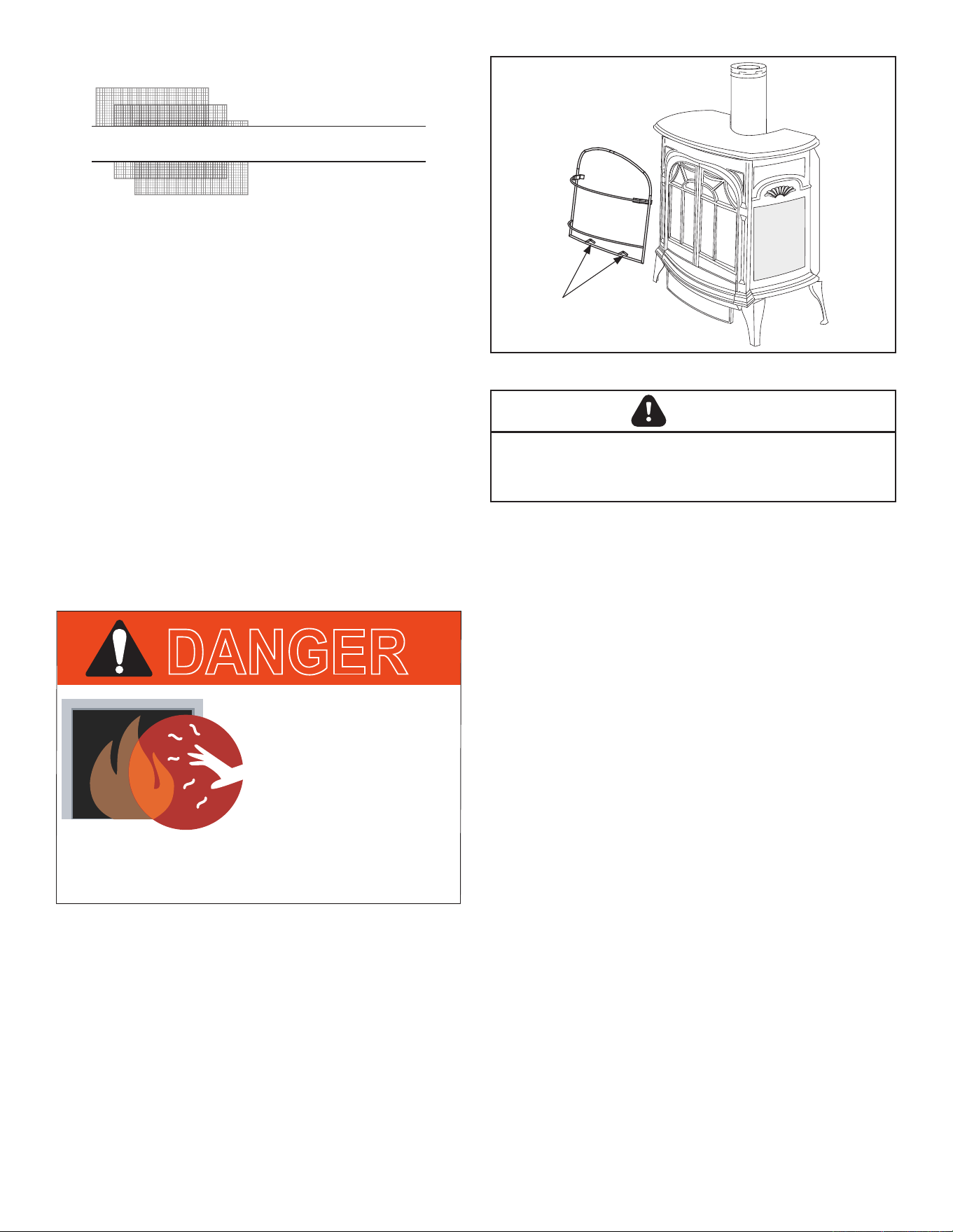
D. Log Set Installation
Before beginning log installation, remove stove front and
glass frame. Refer to Figures 3.24 and 3.25.
Note:Removethesafetybarrierbeforeyouremovethe
glassframe.Toremovethebarrier,simplyliftupandpull
outuntilthetabsareclearoftheircorrespondingslots
ontherebox.Thenproceedtoremovetheglassframe
byfollowingthestepsbelow.
ST474
Stardance
Remove Front
10/3/00
Figure 3.24 - Remove the safety barrier and stove front.
ST208
glass swivel latch
12/99
Figure 3.25 - Release the latches to remove the glass frame.
Before installation, inspect ember bed burner for damage.
Do not use ember bed if damaged or cracked. Small, shallow
surface cracks are acceptable.
1. Remove the logs from their packaging and inspect each
piece for damage. DO NOT INSTALL DAMAGED LOGS.
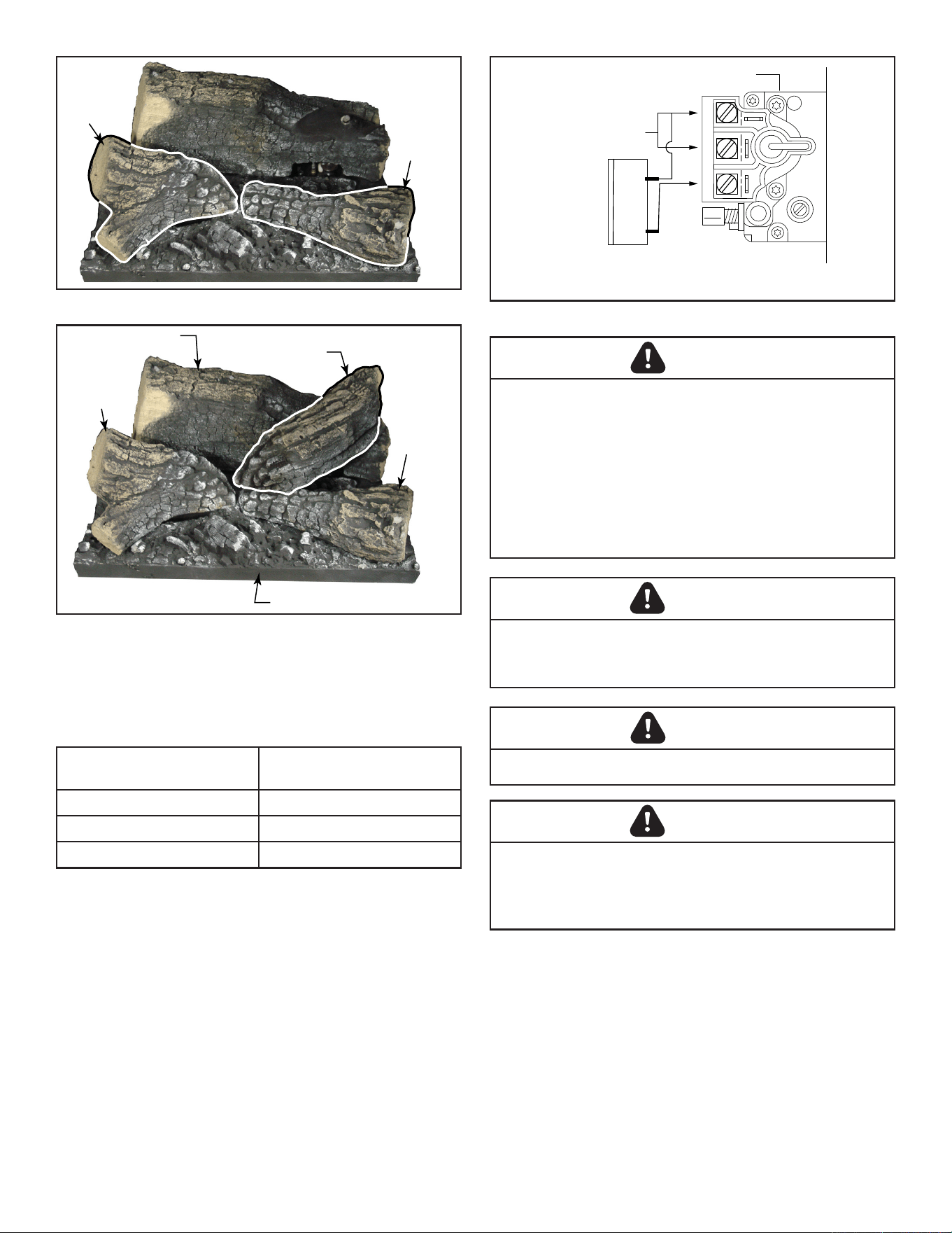
2. Install the rear log by mating the notch on the bottom of
the log with the raised notch on the back left side of the
ember bed, Figure 3.26 Ensure the cutout in the right
side of the log is sitting around the pilot assembly and
pilot is not obstructed, Figure 3.27.
Figure 3.26 - Rear Log
LG497
SDDVT ember bed
6/07
Raised Notch
Pin
Pilot Assembly
Raised
Notch
Figure 3.27 - Ribs for Logs
Lg493
Rear log
6/07
Rear Log
Pilot
Assembly
3. Install the left log by mating the hole on the bottom of the
log with the pin in the ember bed, Figure 3.28. Position
the log over air hole in ember bed.
4. Install the right log by mating the notch on the bottom of
the log with the raised notch on the ember bed, Figure
3.28. Position the log over air hole in ember bed.
5. Install top log by mating hole on bottom of log with
locating pin on top right side of rear log, Figure 3.29.
Position log so it is angled down toward the area where
the front two logs meet.
DANGER
HOT GLASS WILL
CAUSE BURNS.
DO NOT TOUCH GLASS
UNTIL COOLED.
NEVER ALLOW CHILDREN
TO TOUCH GLASS.
A barrier designed to reduce the risk of burns from
the hot viewing glass is provided with this
appliance and must be installed.
2424 3-90-30007467Vermont Castings • Stardance SDDVT Installation Manual_R40 • 09/25
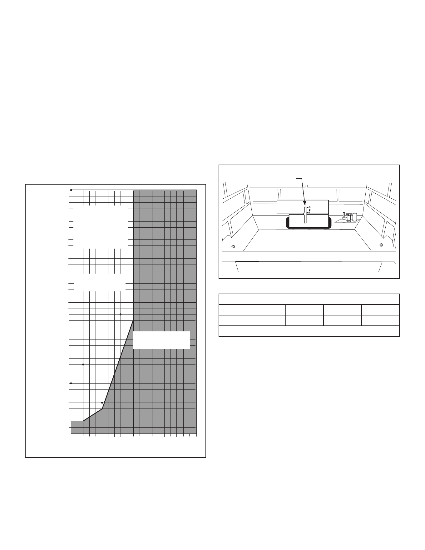
E. Thermostat Connection (optional):
Use only a thermostat rated for 500 - 750 millivolts.
Check the table below for the appropriate gauge thermostat
wire to use for the length of lead required in your installation.
1. Install the wall thermostat in the desired location and run
the wires to the stove location. Terminate these leads
with 1/4" female connectors.
2. Connect the thermostat or wall switch wires to the valve,
Figure 3.30.
Thermostat
Wire/Gauge Maximum Run
18 20 Feet
16 20 - 40 Feet
14 up to 60 Feet
Figure 3.30 - Install wiring to Thermostat before connecting to valve.
SIT VALVE
FP1622
SIT valve w/switch
P
I
L
O
T
TPTH
TP
TH
Valve
Thermopile
Millivolt Thermostat
WARNING
Electrical connections should only be performed by a
qualied, licensed electrician. Main power must be o
when connecting to main electrical power supply or
performing service. All wiring shall be in compliance
with all local, city and state codes. The appliance, when
installed, must be electrically grounded in accordance
with local codes or in the absence of local codes, with the
National Electrical Code ANSI/NFPA 70 (latest edition) and
Canadian Electrical Code, CSA C22.1.
CAUTION
Label all wires before disconnecting when servicing
controls. Wiring errors can cause improper and dangerous
operation.
Figure 3.28 - Front Logs
LG494
left/right logs
6/07
Right Log
Left Log
Figure 3.29 - Completed Installation
LG495
SDDVT logs complete
6/07
Rear Log
Top Log
Left Log
Right Log
Ember Bed
WARNING
Do not connect wall switch to 110 V circuit.
CAUTION
Electrical connections should only be performed by a
qualied, licensed electrician. Main power supply must
be turned o before connecting fans to the main electrical
power supply or performing service.
2525 3-90-30007467Vermont Castings • Stardance SDDVT Installation Manual_R40 • 09/25
WARNING
Electrical Grounding Instructions: This appliance is
equipped with a three-prong (grounding) plug for your
protection against shock hazard and should be plugged
directly into a properly grounded three-prong receptacle.
Connect the Gas Supply Line
Check the Rating Plate attached by a steel cable to the
rebox, to conrm that you have the appropriate rebox
for the type of fuel to be used. The Stardance may be
converted from one gas to another using the appropriate
Fuel Conversion Kit.
In the U.S.; Gas connection should be made in accordance
with current National Fuel Gas Code, ANSI Z223.1/NFPA 54.
Since some municipalities have additional local codes, be
sure to consult your local authority.
In Canada; consult the local authority and CSA-B149.1
installation code.
NOTE: Always check for gas leaks with a mild soap and
watersolution.Donotuseanopenameforleaktesting.
Light the pilot according to the directions in the Operation
section of this manual.
Burner Information
The appliance must only use the gas specied on the rating
plate, unless converted using a Vermont Castings Fuel
Conversion Kit.
THIS APPLIANCE SHOULD BE CONNECTED TO THE
GAS SUPPLY ONLY BY A QUALIFIED GAS SERVICE
TECHNICIAN. FOLLOW ALL LOCAL CODES.
THERE MUST BE A GAS SHUT-OFF BETWEEN THE
STOVE AND THE SUPPLY.
CAUTION
This appliance should only be connected by a qualied gas
technician. Test to conrm manifold pressures as specied
below.
The Stardance Heater and its individual shuto valve must
be disconnected from the gas supply piping during any
pressure testing of that system at test pressures in excess
of 1/2 psig (3.5 kPa).
The Stardance Heater must be isolated from the gas supply
piping system by closing its individual manual shuto valve
during any pressure testing of the gas supply piping system
at test pressure equal to or less than 1/2 psig.
There must be a gas shuto between the stove and the
supply.
In order to connect Natural Gas, use a tting with 1/2" NPT
on the valve side and 1/2" natural gas supply line with an
input of 38,000 BTUs at a manifold pressure of 3.5" between
minimum inlet supply of 5.5" w.c. and maximum of 10.0" w.c.
In order to connect Propane, use a tting with 1/2" NPT
on the valve side and 1/2" propane gas supply line with
an input of 36,000 BTUs at a manifold pressure of 10.0"
between a minimum inlet supply of 11.0" w.c. and maximum
of 13.0" w.c.
2626 3-90-30007467Vermont Castings • Stardance SDDVT Installation Manual_R40 • 09/25
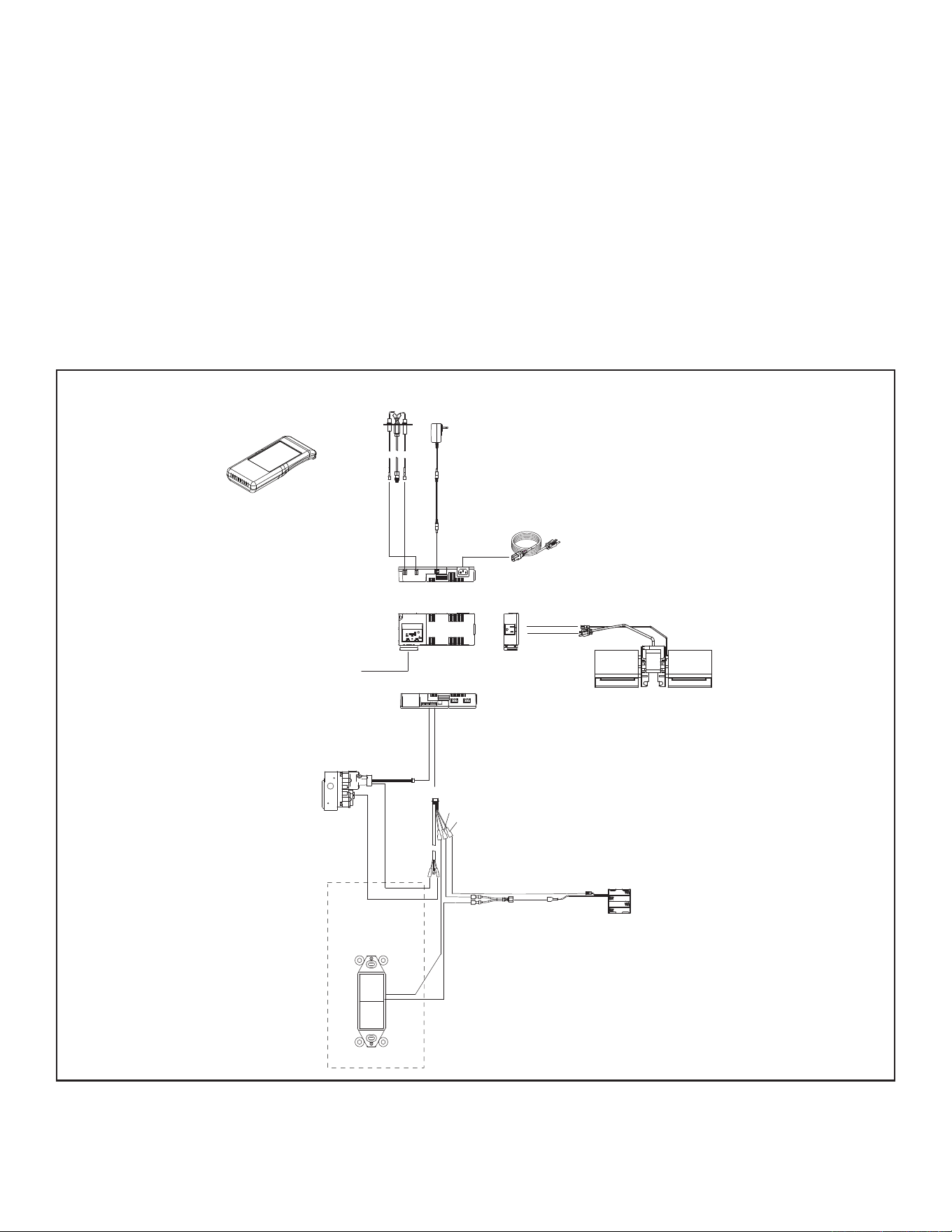
Figure 3.31 - SDDVT-IFT Wiring Diagram
FLAME
SENSE
IGNITER
RF MODULE
6 PIN
BRN
ORANGE
(PILOT)
GREEN
(MAIN)
IFT-RC400
REMOTE
CONTROL
BLK
RED
ROCKER
SWITCH
SPLITTER
BLK
RED
BLK
TO JUNCTION
BOX 110-120 VAC
I
S
6V DC
BATTERY PACK
BLK
3 PRONG 110VAC
GROUND
FAN
F. SDDVT-IFT Wiring Requirements
Intellire™ Touch Ignition System Wiring
• Wire the appliance junction box to 110-120 VAC for
proper operation of the appliance.
WARNING! Risk of Shock or Explosion! DO NOT wire
IFT controlled appliance junction box to a switched circuit.
Incorrect wiring will override IFT safety lockout.
• Refer to Figure 3.31, IFT Wiring Diagram.
• This appliance is equipped with an Intellire™ Touch
control valve which operates on a 6 volt/1.5 AMP system.
• Plug the 6 volt transformer plug into the appliance
junction box to supply power to the unit OR install 4 AA
cell batteries (not included) into the battery pack before
use.
NOTICE: Batteries should only be used as a power source in
the event of an emergency power outage. Batteries should
not be used as a primary long-term power source. Battery
polarity must be correct when installing batteries. When
using batteries as a power source, the 6-volt transformer
must be unplugged from the receptacle.
Do not store batteries in the battery pack when the
appliance is powered by the 6 volt transformer connected to
permanent electrical service.
Accessories Requirements
• This appliance ships standard with a remote control.
Wiring for optional Hearth & Home Technologies
approved accessories should be done now to avoid
reconstruction. Follow instructions that come with those
accessories.
2727 3-90-30007467Vermont Castings • Stardance SDDVT Installation Manual_R40 • 09/25
H. Install the Mesh and Grille
Place the mesh and grille on the top of the Radiance stove
to complete assembly.
NOTE:Abarrierdesignedtoreducetheriskofburnsfrom
the hot viewing glass is provided with this appliance and
shallbeinstalledfortheprotectionofchildrenandother
atriskindividuals.Ifthebarrierbecomesdamaged,the
barriershallbereplacedwiththemanufacturer'sbarrier
forthisappliance.*Anysafetyscreen,guard,orbarrier
removedforservicingtheappliancemustbereplaced
prior to operating the appliance.
* See parts list for model number.
The safety barrier has been designed to work with the doors
open or closed.
1. Remove screen from packaging.
2. Place the two bottom hooks over the bottom edge of the
stove opening, Figure 3.32.
3. Press the screen against the stove snapping the two spring
ngers until the screen ts securely in place.
NOTE:Itistheresponsibilityoftheinstallertoensurethe
barrierisaxedtothestoveatthetimeofinstallation.
CERTIFIED
S
AFETY BARRIER
Figure 3.32 - Install safety barrier screen.
Stardance
Installed Screen
04/19
Bottom Hooks
WARNING
The safety screen barrier must be installed after the glass
front is in place. It is not a replacement for the glass and
the unit must not be operated without the glass in place.
G. Install the Safety Barrier
DANGER
HOT GLASS WILL
CAUSE BURNS.
DO NOT TOUCH GLASS
UNTIL COOLED.
NEVER ALLOW CHILDREN
TO TOUCH GLASS.
A barrier designed to reduce the risk of burns from
the hot viewing glass is provided with this
appliance and must be installed.
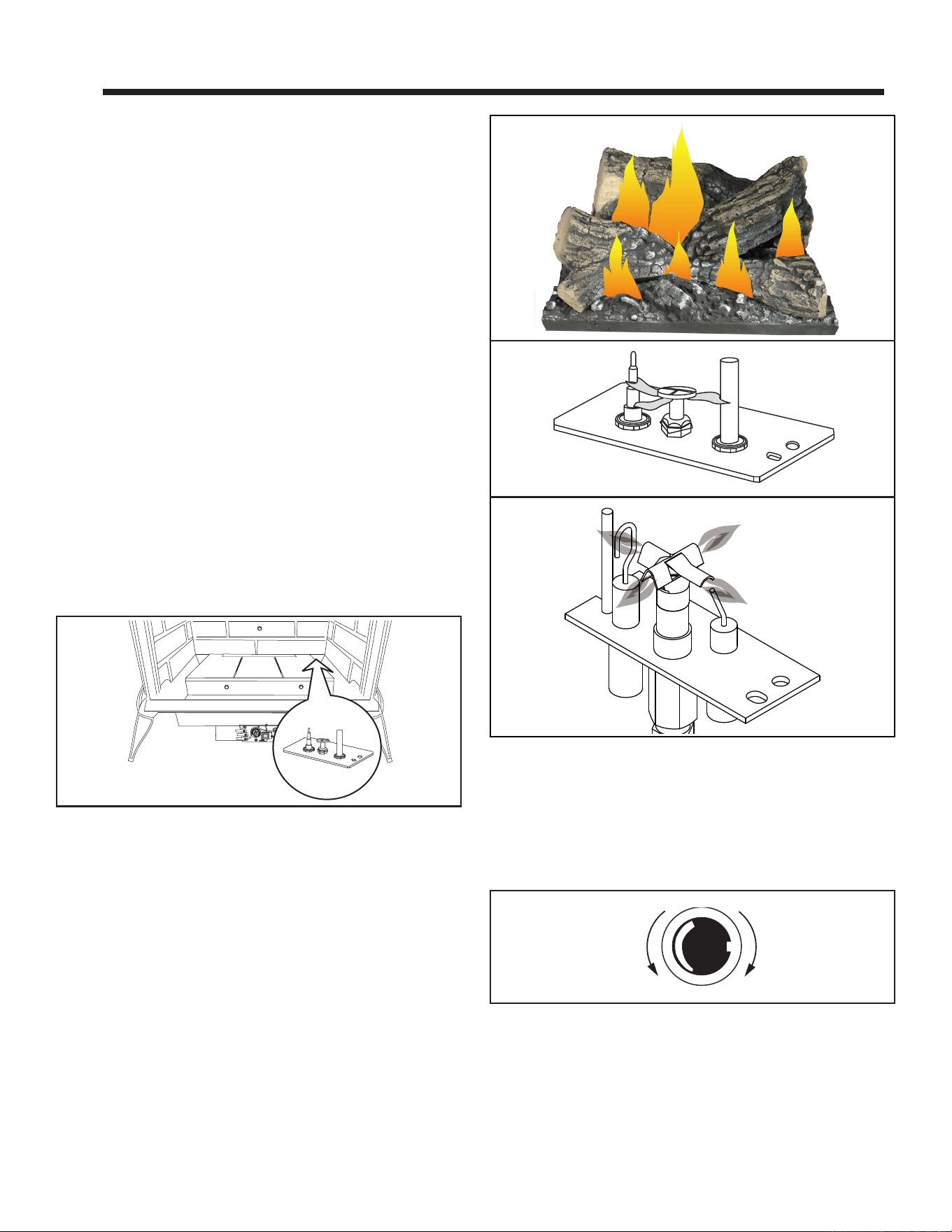
2828 3-90-30007467Vermont Castings • Stardance SDDVT Installation Manual_R40 • 09/25
A. Operation
The Stardance is operated with the front plate in place with
the doors open or closed. To open the front doors, pull forward
to separate the magnetic catch. Ensure the safety barrier
screen is in place during operation.
B. Lighting Instructions
Read these instructions carefully and familiarize yourself with
the lighting instructions. Section F, “Lighting and Operating
Instructions”. Locate the pilot assembly, Figure 4.1. Follow
the lighting instructions in this manual exactly.
During the rst re, it is not unusual to smell some odor
associated with new logs, paint and metal being heated.
Odors should dissipate within the rst eight to ten hours,
however, you can open a window to provide fresh air to
alleviate the condition.
C. Pilot and Burner Inspection
Each time you light your heater check that the pilot ame and
burner ame patterns are as shown in Figure 4.2. If ame
patterns are incorrect, turn the heater o. Contact your dealer
or a qualied gas technician for assistance. Do not operate
the heater until the pilot ame is correct.
Follow regular maintenance procedures as described in the
Cleaning and Maintenance section of this manual.
E. Flame & Temperature Adjustment
For SDDVT models which are equipped with HI/LO valves,
ame adjustment is accomplished by rotating the HI/LO
adjustment knob located near the center of the gas control
valve, Figure 4.3.
ST477a
Stardance
pilot location
10/4/00
Figure 4.1 - Pilot Assembly location.
Pilot Assembly
D. Flame Characteristics
It is important to periodically perform a visual check of the
pilot and the burner ames. Compare them to Figure 4.2. If
any of the ames appear abnormal, call a service person.
Figure 4.2 - Correct pilot and burner ame appearance.
SDDVT MODELS
SDDVT-IFT
LG500
Intrepid log flames
7/07
CO105d
Pilot flame
6/07 djt
Figure 4.3 - Flame adjustment knob for SIT valve.
L
O
H
I
FP390
FLAME ADJUSTMENT KNOB
11/21/96
Turn
counterclockwise
to increase
flame height
Turn clockwise
to decrease
flame height
4 4
Operating Instructions
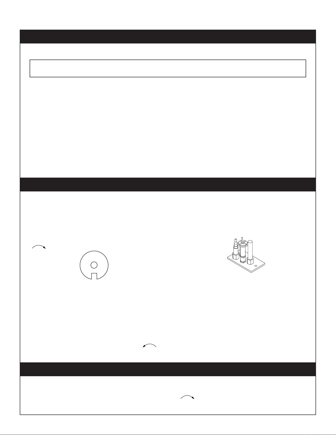
2929 3-90-30007467Vermont Castings • Stardance SDDVT Installation Manual_R40 • 09/25
1. STOP! Read the safety information above.
2. Turn o all electrical power to the stove.
3. Turn the On/O switch to “OFF" position, set the remote
to OFF or set thermostat to lowest level.
4. Open control access panel.
5. Push in gas control knob slightly and turn clockwise
to “OFF".
FOR YOUR SAFETY READ BEFORE LIGHTING
A. This heater has a pilot which must be lit manually. When
lighting the pilot follow these instructions exactly.
B. BEFORE LIGHTING smell all around the heater area
for gas. Be sure to smell next to the oor because some
gas is heavier than air and will settle on the oor.
WHAT TO DO IF YOU SMELL GAS
• Do not try to light any stove
• Do not touch any electric switch
• Do not use any phone in your building
• Immediately call your gas supplier from a neighbor’s
phone. Follow the gas supplier’s instructions.
• If you cannot reach your gas supplier, call the Fire
Department
LIGHTINGANDOPERATINGINSTRUCTIONSFORSDDVTMODELS(MILLIVOLTONLY)
Lighting Instructions
3/8" - 1/2"
FP1068
Lighting instructions
Pilots
SIT NOVA
PILOT
ON
OFF
ON
P
I
L
O
T
O
F
F
O
F
F
FP1067
lighting instruction
knobs
3/9/01 djt
5
4
3
2
1
O
F
F
P
i
l
o
t
WARNING:Ifyoudonotfollowtheseinstructionsexactly,areorexplosion
may result causing property damage, personal injury or loss of life.
1. Turn the On/O switch to O position or set the thermostat
to lowest setting.
2. Turn o all electric power to the stove if service is to be
performed.
3. Open control access panel.
4. Push in gas control knob slightly and turn clockwise
to “OFF". Do not force.
5. Close control access panel.
• If knob does not pop up when released, stop and
immediately call your service technician or gas supplier.
• If after several tries, the pilot will not stay lit, turn the gas
control knob to “OFF" and call your service technician
or gas supplier.
11. Replace glass door.
12. Turn gas control knob to “ON" position.
13. Turn the On/Off switch to “ON" position or set
thermostat to desired setting.
14. Turn on all electrical power to the stove.
10. Push the control knob all the way in and hold. Immediately
light the pilot by repeatedly depressing the piezo spark
ignitor until a ame appears. Continue to hold the
control knob in for about one (1) minute after the pilot
is lit. Release knob and it will pop back up. Pilot should
remain lit. If it goes out, repeat steps 5 through 8.
6. Wait ve (5) minutes to clear out any gas. Then smell
for gas, including near the oor. If you smell gas, STOP!
Follow “B" in the safety information above. If you do not
smell gas, go to the next step.
7. Remove glass door before lighting pilot. (See Glass
Frame Removal section).
8. Visibly locate pilot by the main burner.
9. Turn knob on gas control counter-clockwise to
“PILOT".
C. Use only your hand to push in or turn the gas control
knob. Never use tools. If the knob will not push in or turn
by hand, do not try to repair it, call a qualied service
technician. Applying force or any attempted repair may
result in a re or explosion.
D. Do not use this stove if any part has been under water.
Immediately call a qualied service technician to inspect
the heater and to replace any part of the control system
and any gas control which has been under water.
ToTurnOGasToHeater
F. Lighting and Operating Instructions
3030 3-90-30007467Vermont Castings • Stardance SDDVT Installation Manual_R40 • 09/25
Symptom PossibleCauses Corrective Action
Spark Ignitor will not
light
1. Defective or misaligned
electrode at pilot
1. Using a match, light pilot. If pilot lights, turn o pilot and push the red button
again. If pilot will not light - check gap at electrode and pilot-should be 1/8” to
have a strong spark.
2. Defective ignitor (push
button)
2. With the control knob in the pilot position, push the control knob all the way and
hold. Check for spark at electrode and pilot. If no spark to pilot, and electrode
wire is properly connected, replace the battery in the ignitor module and try
again. Refer to Maintenance Section. If the problem still exists, replace the
ignitor module box.
Pilot will not stay
lit after carefully
following lighting
instructions
1. Defective pilot generator
(thermocouple), remote
wall switch
1. Check pilot ame. Must impinge on thermocouple/thermopile. NOTE: This
pilot burner assembly utilizes both a thermocouple and a thermopile. The
thermocouple operates the main valve operation (On and O). Clean and or
adjust pilot for maximum ame impingement on thermopile and thermocouple.
2. Defective automatic valve 2. Turn valve knob to “Pilot”. Maintain ow to pilot; millivolt meter should read
greater than 10mV. If the reading is okay and the pilot does not stay on, replace
the gas valve. NOTE: An interrupter block (not supplied) must be used to
conduct this test.
Pilot burning, no
gas to main burner
1. Wall switch or wires
defective
1. Check wall switch and wires for proper connections. Jumper wire across
terminals at wall switch, if burner comes on, replace defective wall switch.. If
okay, jumper wires across wall switch wires at valve, if burner comes on, wires
are faulty or connections are bad.
2. Thermopile may not be
generating sucient
millivoltage
• Be sure wire connections form thermopile at gas valve terminals are tight
and thermopile is fully inserted into pilot bracket.
• One of the wall switch wires may be grounded. Remove wall switch wires
form valve terminals if pilot now stays lit, trace wall switch wiring for ground.
May be grounded to stove or gas supply.
• Check thermopile with millivolt meter. Take reading at thermopile terminals
of gas valve. Should read 250-300 millivolts (minimum 150) while holding
valve knob depressed in pilot position and wall switch “O”. Replace faulty
thermopile if reading is below specied minimum.
3. Plugged burner orice 3. Check burner orices for debris and remove.
4. Defective automatic valve
operator
4. Turn valve knob to “On”, place wall switch to “On” millivolt meter should read
greater than 150mV. If the reading is okay and the burner does not come on,
replace the gas valve.
Frequent pilot
outage problem
1. Pilot ame may be too low
or blowing (high) causing
the pilot safety
to drop out
1. Clean and/or adjust pilot ame for maximum ame impingement on thermopile
and thermocouple.
2. Possible blockage of the
vent terminal
2. Check the vent terminal for blockage (recycling the ue gases)
GasControlSystem(SDDVTmodels)
SIT NOVA 820 Millivolt Valve
NOTE:Beforetroubleshootingthegascontrolsystem,besureexternalgasshutoisinthe“On”position.
G.Troubleshooting
3131 3-90-30007467Vermont Castings • Stardance SDDVT Installation Manual_R40 • 09/25
FOR YOUR SAFETY READ BEFORE LIGHTING
A. This appliance is equipped with an ignition device which automatically lights the pilot. Refer to the instructions.
B. BEFORE OPERATING smell all around the appliance area for gas. Be sure to smell next to the oor because some
gas is heavier than air and will settle on the oor.
WHAT TO DO IF YOU SMELL GAS:
• Do not attempt to light any appliance.
• Do not touch any electric switch; do not use any phone in your building.
• Immediately call your gas supplier from a neighbor's phone. Follow the gas supplier's instructions.
• If you cannot reach your gas supplier, call the re department.
C. Use only your nger to push in the master switch. Never use tools. If the switch will not function by hand, do not try
to repair it. Call a qualied service technician. Force or attempted repair may result in a re or explosion.
D. Do not use this appliance if any part of it has been under water. Immediately call a qualied service technician to
inspect the appliance and to replace any part of the control system and any gas control that has been under water.
WARNING
If you do not follow these instruction exactly, a re or explosion may result causing property damage,
personal injury or loss of life.
H. Read Before Lighting
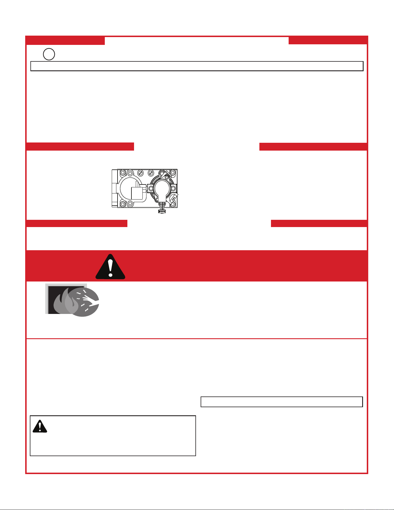
3232 3-90-30007467Vermont Castings • Stardance SDDVT Installation Manual_R40 • 09/25
FOR YOUR SAFETY READ BEFORE LIGHTING
TO TURN OFF GAS TO APPLIANCE
1. This appliance is equipped with an ignition device which
automatically lights the burner. DO NOT try to light the burner by hand.
1. Equipped with wall switch: Turn ON/OFF switch to OFF.
Equipped with remote or wall control: Press OFF button.
Equipped with thermostat: Set temperature to lowest setting.
WARNING: If you do not follow these instructions exactly, a fi re or explosion may result causing property damage, personal injury or loss of life.
WARNING:
NOT FOR USE WITH SOLID FUEL
GAS
VALVE
For additional information on operating your
Hearth & Home Technologies fi replace, please
refer to www.hearthnhome.com.
A. This appliance is equipped with an intermittent pilot ignition (IPI) device which
automatically lights the burner. DO NOT try to light the burner by hand.
B. BEFORE LIGHTING, smell all around the appliance area for gas. Be sure to smell
next to the fl oor because some gas is heavier than air and will settle on the fl oor.
WHAT TO DO IF YOU SMELL GAS
• DO NOT try to light any appliance.
• DO NOT touch any electric switch; do not use any phone in your building.
DO NOT CONNECT LINE VOLTAGE (110/120 VAC OR 220/240 VAC) TO THE CON-
TROL VALVE.
Improper installation, adjustment, alteration, service or maintenance can cause injury
or property damage. Refer to the owner’s information manual provided with this ap-
pliance. For assistance or additional information, consult a qualifi ed installer, service
agency or the gas supplier.
This appliance needs fresh air for safe operation and must be installed so there are
provisions for adequate combustion and ventilation air.
Hot while in operation. DO NOT touch. Keep children, clothing, furniture, gasoline
and other liquids having fl ammable vapors away.
DO NOT operate the appliance with fi xed glass assembly removed, cracked or
broken. Replacement of the fi xed glass assembly should be done by a licensed or
qualifi ed service person.
• Immediately call your gas supplier from a neighbor’s phone. Follow the gas sup-
plier’s instructions.
• If you cannot reach your gas supplier, call the fi re department.
C. Use only your hand to push in or turn the gas control knob. Never use tools. If
the knob will not push in or turn by hand, DO NOT try to repair it, call a qualifi ed
service technician. Force or attempted repair may result in a fi re or explosion.
D. DO NOT use this appliance if any part has been under water. Immediately call
a qualifi ed service technician to inspect the appliance and to replace any part of
the control system and any gas control which has been under water.
For use with natural gas and propane. A conversion kit, as supplied by the manufac-
turer, shall be used to convert this appliance to the alternate fuel.
Also Certifi ed for Installation in a Bedroom or a Bedsitting Room.
,enon fi ;yna fi ,sedoc lacol htiw ecnadrocca ni dellatsni eb tsum ecnailppa sihT
follow the National Fuel Gas Code, ANSIZ223.1/ NFPA 54, or the National Gas and
Propane Installation code, CSA B149.1.
LIGHTING INSTRUCTIONS (IPI)
2. Wait fi ve (5) minutes to clear out any gas. Then smell for gas, including near the
fl oor. If you smell gas, STOP! Follow “B” in the Safety Information located on the
top of this label. If you do not smell gas, go to next step.
3. To light the burner:
Equipped with wall switch: Turn ON/OFF switch to ON.
Equipped with remote or wall control: Press ON or FLAME button.
Equipped with thermostat: Set temperature to desired setting.
4. If the appliance does not light after three tries, call your service technician or gas
supplier.
2. Service technician should turn off electric power to the control when performing
service.
DANGER
HOT GLASS WILL CAUSE BURNS.
DO NOT TOUCH GLASS UNTIL COOLED.
NEVER ALLOW CHILDREN TO TOUCH GLASS.
CAUTION:
A barrier designed to reduce the risk of burns from the hot viewing glass is provided with this
appliance and must be installed for the protection of children and other at-risk individuals.
593-913K
WARNING: This product and the fuels used to operate this
product (liquid propane or natural gas), and the products
of combustion of such fuels, can expose you to chemicals
including benzene, which is known to the State of California to cause
cancer and reproductive harm. For more information go to: www.
P65Warnings.ca.gov.
Keep burner and control compartment clean. See installation and operating instructions
accompanying appliance.
I.LightingInstructions(IFT)
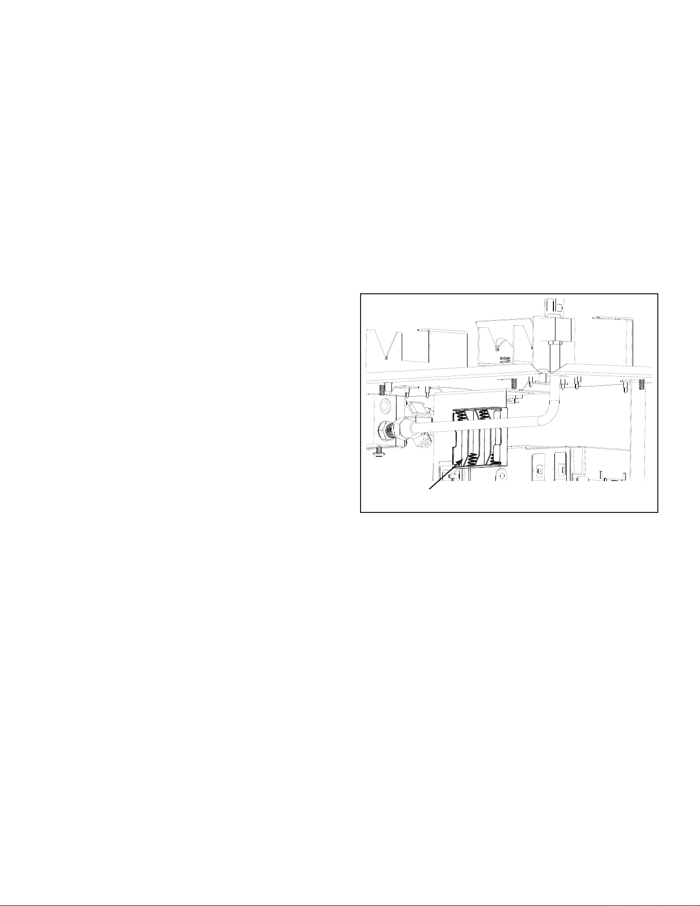
3333 3-90-30007467Vermont Castings • Stardance SDDVT Installation Manual_R40 • 09/25
J. Operation During A Power Outage -
IntelliFire™ Touch
The IntelliFire™ Touch intermittent pilot ignition system
comes with a battery backup system that enables the system
to operate in a power outage. The system oers seamless
transition from household AC power to battery backup. A
factory-installed battery pack is located in the control cavity
of the appliance. See Figure 3.5. Battery longevity and
performance will be aected by long term exposure to the
service temperatures of this appliance.
NOTICE: Batteries should only be used as a power source
in the event of an emergency power outage. Batteries
should not be used as a primary long-term power source.
To Operate Fireplace Using Battery Power (DC):
1. Access the control cavity of the appliance. The magnetic
vanity plate may need to be removed.
2. Locate the battery tray (located on the back of the ECM
bracket) and insert four AA cell batteries, Figure 4.4.
Battery polarity must be correct or module damage will
occur, Figure 4.5. A complete wiring diagram is included
in the Electrical section of the appliance Installation
Manual.
3. Turn the appliance on according to the instructions below
for the appropriate type of control:
Standard Wall Switch:
• Toggle the switch as you would under normal
circumstances.
Wireless Remote:
• Remote receiver is integrated into the ignition module
• Use the remote to turn the appliance on.
• To preserve battery life, do not use the HI/LO ame or
THERMOSTAT options.
Ignition Module:
• Locate the ignition module in the control cavity.
• Slide the ON/REMOTE/OFF switch to the ON position
NOTICE: Some functionality will be lost when using battery
backup including remote control, fan, lights, or any other
auxiliary functions that require household 110-120 VAC
power
To Return to Operation Using Electrical (AC) Power
Standard Wall Switch or Factory-Installed ON/OFF
Switch:
• Toggle the switch to OFF and remove the batteries
from the battery tray. Replace magnetic vanity plate on
appliance.
Wireless Remote:
• Slide the ON / REMOTE / OFF switch to the REMOTE
position. Remove the batteries from the battery tray.
Replace decorative front on appliance.
Ignition Module:
• Slide the ON / REMOTE / OFF switch to the REMOTE
position.
• Remove the batteries from the battery tray. Replace
decorative front on appliance.
Battery Holder
Figure 4.4 - Battery Holder
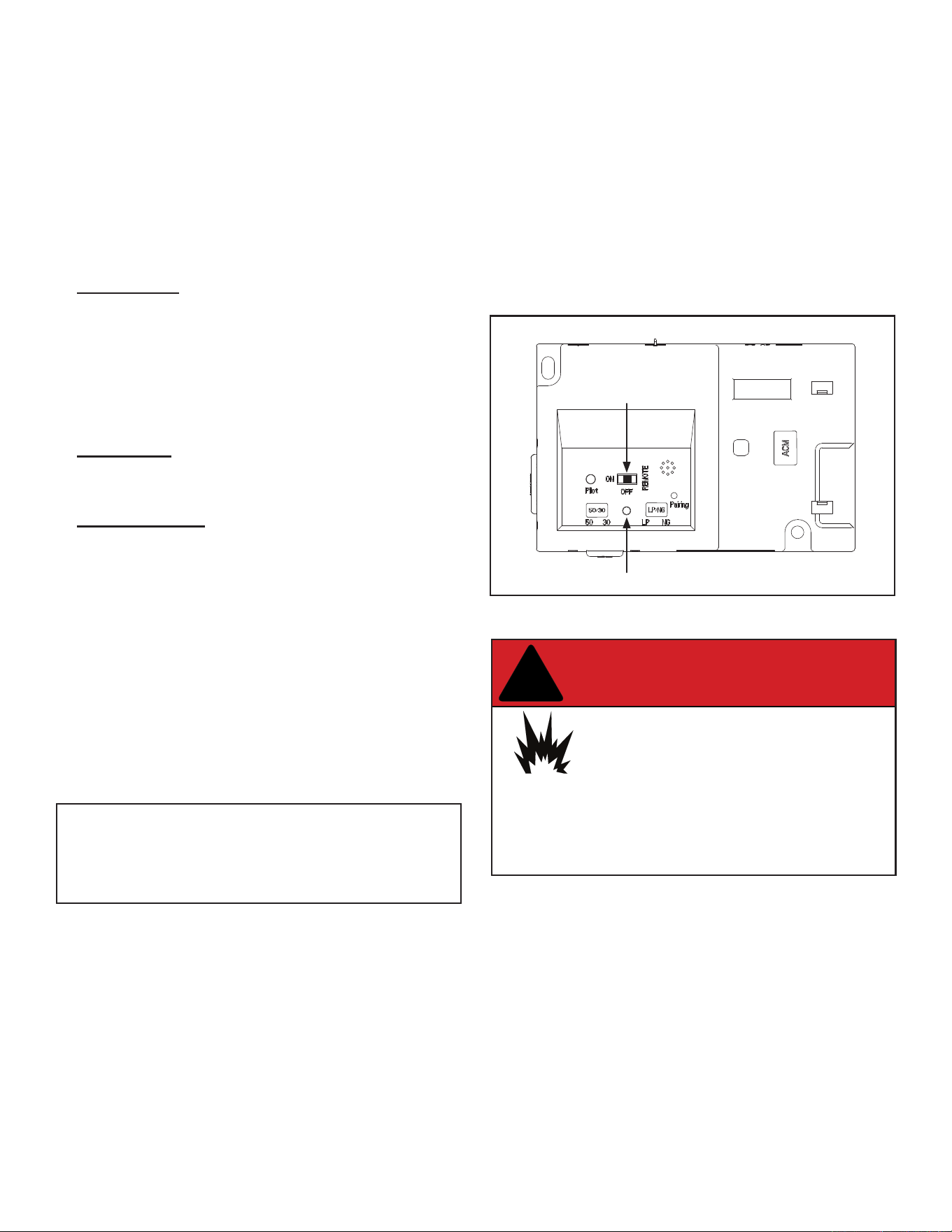
3434 3-90-30007467Vermont Castings • Stardance SDDVT Installation Manual_R40 • 09/25
K. Detailed Component Operating Instructions
- IntelliFire™ Touch
IFT-ECM Detailed Operating Instruction
This model is shipped from the factory equipped with the
IFT-RC400 remote.
1. The Electronic Control Module (IFT-ECM) has a three-
position ON/OFF/REMOTE selector switch that must
be set for proper operation, Figure 4.5. When changing
switch positions, it is important to pause in each position
for 1-2 seconds.
OFF Position:
The appliance will not respond to any commands from
a wired wall switch or IFT-RC400 remote controls. The
unit should be in the OFF position during service, fuel
conversion, and to reset the IFT-ECM in the event the
system goes into a LOCK-OUT mode as the result of a
system error. When switched to the OFF position while
the appliance is operating, the system will shut down.
ON Position:
The appliance will ignite and run continuously at the HI
ame setting. No adjustment in ame height is possible.
Remote Position:
The remote position allows operation of the appliance
from a wired wall switch or IFT-RC400 remote controls.
The IFT-ECM switch must be in this position to pair the
IFT-ECM with the IFT-ACM (if installed), and/or IFT-
RC400 remote controls. See the IFT-RC400 installation
manual for detailed instructions on pairing the IFT-ECM
with the remote controls.
After successfully pairing a IFT-RC400, all installed
accessories can be controlled by the IFT-RC400 (see
IFT-RC400 user manual). The IFT-ECM has a safety
feature that will automatically shut down the replace
after 9 hours of continuous operation without receiving a
command from the IFT-RC400.
The IFT-ECM has a safety feature that will
automaticallyshutdownthereplace after9hours
of continuous operation in the ON position, except
when operated in active thermostat mode.
2. If multiple control options are installed, the IFT-ECM will
respond to the last command from the wired wall switch
or IFT-RC400. The wired wall switch is NOT available if
a Power Vent is used.
3. The Pilot button on the IFT-ECM activates the Cold
Climate function of the replace. This function lights the
pilot ame ONLY to provide enough heat in the rebox
to reduce condensation in cool, high humidity ambient
conditions. To activate the Cold Climate press and hold
the Pilot button for one second and release. The IFT-
ECM will ash two green LED blinks, beep twice and
light and rectify the pilot ame when pressed to activate.
To turn o Cold Climate, press and hold the Pilot button
for one second and release. The IFT-ECM will ash one
green LED blink, beep once and shut down the pilot
ame. If remote controls are paired with the IFT-ECM,
this feature can also be activated with the IFT-RC400.
Top View
LED Indicator
3 Position Switch
Figure 4.5 - IFT-ECM
DANGER
Risk of Explosion
DO NOT cycle the ON/OFF/REM selector switch
more than one time within a ve minute period.
Gas may accumulate in rebox. Call a quali ed
service technician.
!

3535 3-90-30007467Vermont Castings • Stardance SDDVT Installation Manual_R40 • 09/25
4. An IFT-ECM reset is required if the module is in a lock-out
condition. When this occurs, the appliance is shut down
and the IFT-ECM status indicator LED will be blinking a
RED/GREEN error code along with a one-time audible
double- beep. If the IFT-ECM is in a lock-out condition,
refer to the troubleshooting chart to interpret the error
code and take corrective action as required. To reset the
IFT-ECM after a lock-out error:
CAUTION! Risk of burns! Appliance surfaces are hot
when operating and during cool down. Use care and wear
gloves when opening the front and accessing components
inside the appliance.
- Be aware the appliance may be HOT, use care in
accessing the IFT-ECM.
- Set the IFT-ECM 3-position selector switch to OFF
position.
- Wait ve (5) minutes to allow possible accumulated
gas to clear.
- Set the IFT-ECM 3-position selector switch to ON or
REMOTE position. Module will beep once and ash a
three GREEN LED code on successful startup.
- If placed in ON position, the appliance will ignite
normally if the error condition was corrected.
- If placed in REMOTE position, use the paired IFT-
RC400 or wired wall switch to start the appliance;
appliance will ignite normally if the error condition
was corrected.
- If the IFT-ECM re-enters the lock-out condition after
these steps, call your dealer for service.
IntelliFireTM Touch Ignition System
NOTICE: Batteries should not be placed in the battery
pack while using the transformer. Remove batteries before
using the transformer, and unplug the transformer before
installing the batteries. Battery polarity must be correct or
module damage will occur.
ApplianceON/OFF:
This model is supplied with a fully functional remote control.
This remote controls:
• ON/OFF Functions
• Flame height adjustments
• Thermostat
• Cold Climate Feature
• Fan Speed
Please refer to the instructions included with the remote
control for more detailed operating instructions.
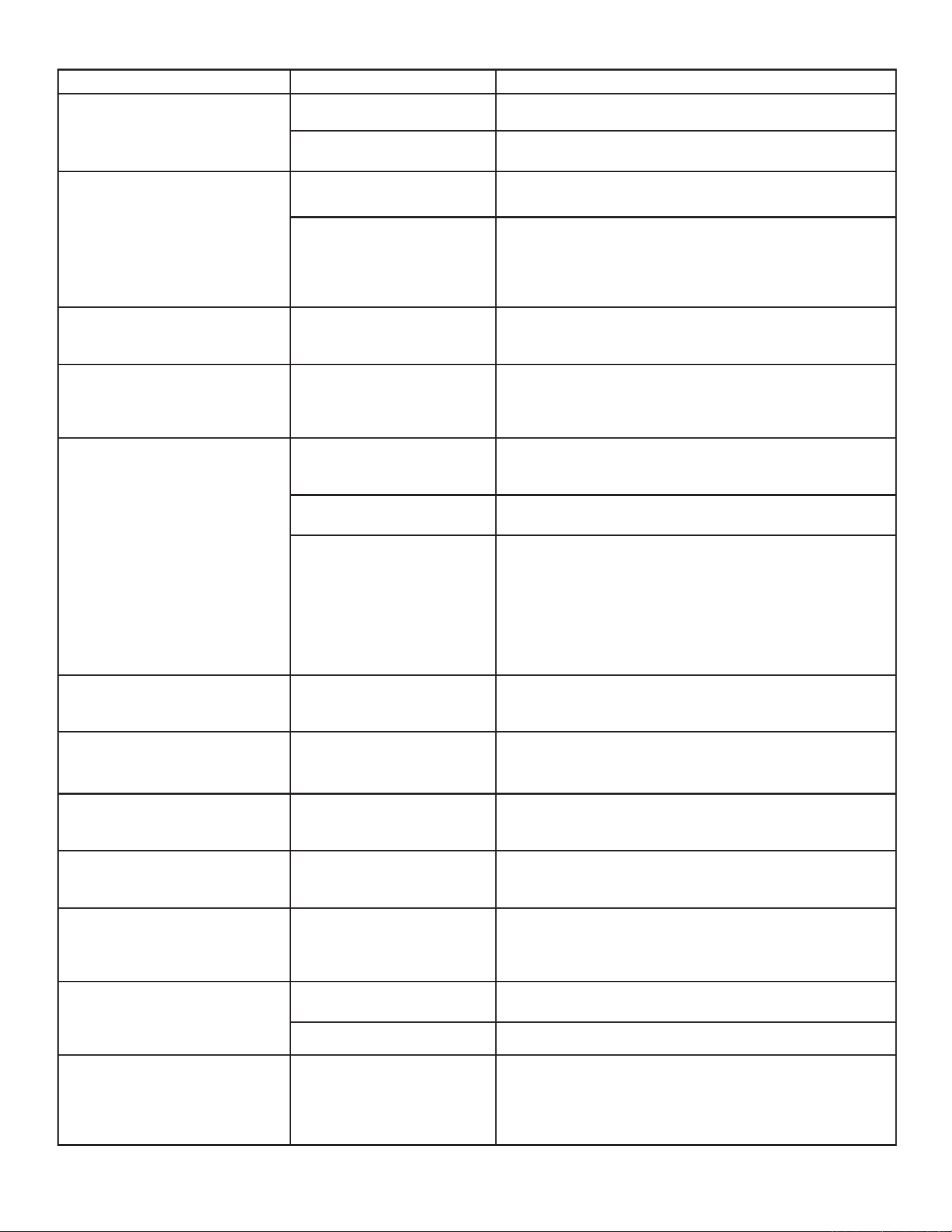
3636 3-90-30007467Vermont Castings • Stardance SDDVT Installation Manual_R40 • 09/25
L.FrequentlyAskedQuestions-IntelliFire™TouchControls(IFT-RC400)
Symptom PossibleCause Corrective Action
The appliance does not respond to
commands from the remote control
display does not light up when
screen is touched.
Batteries are depleted. Verify batteries are new.
Batteries are incorrectly
oriented.
Verify batteries are installed in correct orientation as shown on
batteries receptacle.
The display on remote lights up
when screen is touched but it does
not respond to commands.
Touchscreen has lost
calibration.
Touchscreen needs to be re-calibrated. Call dealer to have
screen re-calibrated.
Child Lock is ON.
Check child lock icon located at the top of the remote display. If
ON, it will show as a ‘locked’ symbol. To unlock, remove battery
compartment door, locate child lock switch and move to ‘unlock’
position. Verify child lock icon on screen is now displayed in ‘un-
lock’ position.
The remote displays the following
message on-screen:
No dealer info available
Dealer information not
programmed into remote.
Remote will still provide all available functions, and appliance is
fully available for use. Call dealer to have them program.
The remote displays the following
message on-screen:
Call “Dealer Name & Number” to
schedule maintenance.
300 hours of use. Appliance is
still fully functional.
The appliance has been burning for 300 hours and is due for a
regular maintenance. Call dealer to have them perform mainte-
nance.
The room temperature displayed
on the remote is either slow or
quick to respond while operating in
thermostat mode.
Remote is placed at a very
short distance or too far away
from the appliance.
Try to keep the remote close to the appliance but not directly in
front of it. The remote acts as the thermostat.
Remote is placed in the path of
an air draft or vent.
Move the remote away from the direct path of air ow. The re-
mote acts as the thermostat.
Flame Modulation
The control system is designed to automatically adjust the
ame intensity based on the dierence between the desired
room temperature, and actual temperature. In thermostat
mode, the hearth appliance will start in HI ame, but as the
actual temperature approaches the desired set temperature on
the remote, the ame intensity will automatically decrease. Au-
tomatic ame modulation will result in more control of the tem-
perature, and will cause the appliance to cycle OFF/ON less.
The appliance turns OFF the ame
after extended periods of operation
9 hour safety shutdown timer
This is normal behavior. The appliance has a safety timer that
will automatically turn OFF the ame after nine hours of
uninterrupted operation.
The remote displays the following
message on-screen: Fan will turn
on within 3 minutes
Functioning as intended.
The appliance has a three minute delay timer before the fan is
turned ON. This allows the air surrounding the appliance to be
heated before being pushed into the room.
The remote displays the following
message on-screen:
“Replace remote batteries."
Low batteries in remote. Install new batteries in the remote.
The remote is displaying an
incorrect brand.
Remote was programmed
incorrectly.
Call dealer to have them program the remote with correct
branding. Remote is still fully functional and the appliance is
unaected.
After turning ame ON using
remote, the ame does not turn
ON immediately and instead a two
minute timer is displayed.
Power vent is installed on the
appliance.
This is expected behavior and the two minute timer is called a
pre-purge timer. The ame will turn ON at the expiration of the
timer.
The remote displays the following
message on-screen:
“Remote Control Communication
Error.”
No power to appliance.
Verify home circuit breaker is on and master reset is on (if
equipped).
Power outage. Install new batteries in battery backup.
The remote displays the following
message on -screen: Sorry your
appliance did not start. Try again
by pressing Flame On.
No power to appliance. No gas
to appliance. Accumulation
of air in gas line from extended
period of appliance inactivity.
Gas control system failure.
Verify that appliance has power and gas. Verify that the appli-
ance accepts ame ON commands with an audible beep, and
successfully turns ame on within 90 seconds. If this failure
persists, contact dealer for service.
3737 3-90-30007467Vermont Castings • Stardance SDDVT Installation Manual_R40 • 09/25
M.Troubleshooting
With proper installation, operation, and maintenance your gas appliance will provide years of trouble-free service. If you do
experience a problem, this troubleshooting guide will assist a qualied service technician in the diagnosis of a problem and
the corrective action to be taken. This troubleshooting guide can only be used by a qualied service technician. Contact your
dealer to arrange a service call by a qualied service technician.
IntelliFire™ Touch
Error Codes
ECM LED
Error Codes
Description
3 Red: 1 Green IFT-RC400 error message: ‘Appliance Safely Disabled’, pilot sparks for 90 sec, no ame-rectication.
2 Red: 1 Green IFT-RC400 display: ‘Error Pilot Flame’, pilot valve solenoid not detected.
2 Red: 2 Green Sparking feedback signal error, spark coil failure.
5 Red: 1 Green IFT-RC400 display: ‘Error Power Vent’ (if installed).
See Troubleshooting matrix for more detail on Lock-out Error Codes, Possible Causes and Corrective Actions.
Troubleshooting:
Symptom PossibleCause Corrective Action
Pilot won’t light, module clicks but no
spark 90 sec, 3 Red/1 Green Lock out.
Incorrect wiring.
Verify ‘S’ (White) sense wire and ‘I’ (orange) ignitor wire
are connected to correct terminals on IFT-ECM.
Loose connections or
electrical shorts in wiring.
Verify no loose connections or electrical shorts in wiring
from module to pilot assembly. Verify wire insulation is not
damaged. Verify wires are not grounding out to chassis,
pilot burner, or any other metal object. Replace any
damaged wires.
Ignitor gap is too large.
Verify spark gap is approximately 0.095” (2.41 mm) to
0.135” (3.43 mm).
Pilot won’t light, there is no noise or spark.
No AC power, AC/DC adaptor
faulty, backup batteries (if
being used) depleted, IFT-
ECM slider switch in OFF
position.
Verify IFT-ECM slider switch is in ON or REM position.
Verify AC power available to junction box. Verify AC/DC
adaptor is plugged into junction box and ECM. Verify AC/
DC adaptor output voltage is between 5.7-6.3 Vdc. If
battery pack is used, check battery pack voltage is >4.2 V
(if not, replace batteries).
Shorted or loose connection
in system wiring or wiring
harness.
Verify system wiring conguration. Remove and reinstall
wiring harness that plugs into module. Check continuity
of wires in valve wiring harness. Replace any damaged
components.
Poor or no system ground.
Verify black ground wire in valve harness is connected to
metal chassis of replace.
Pilot won’t light, there is no noise or spark,
2 Red/1 Green Lockout.
Pilot solenoid not detected.
Check if valve harness orange wire is connected to pilot
solenoid valve. Check pilot solenoid resistance, nominal
is 40 ohms. If open or shorted, replace valve. Check valve
harness wire continuity, if open replace 6-pin harness.
Pilot won’t light, there is no noise or spark,
2 Red/2 Green Lockout.
Spark coil failure. Replace ECM.
3838 3-90-30007467Vermont Castings • Stardance SDDVT Installation Manual_R40 • 09/25
M.Troubleshooting-(Continued)
Symptom PossibleCause Corrective Action
Pilot sparks but does not light, after 90
sec, 3 Red/1 Green Lockout
No gas supply.
Verify incoming gas line ball valve is ‘Open’. Verify inlet
pressure is within requirement for gas type used. Contact
gas supplier.
ECM has poor ground.
Verify wiring, check valve harness black wire is securely
grounded to metal chassis.
Gas valve defective.
Check pilot valve solenoid kick and hold voltages during
ignition cycle. Kick V should be >1 V, hold V minimum
0.26 V. If voltages are OK, replace gas valve.
Pilot lights but main burner does not
light. Pilot continues to spark for 90 sec
then goes into 3 Red/1 Green Lockout.
No ame detected. Flame
rectication issue.
Check if white sense lead is securely connected to
‘S’ terminal of IFT-ECM. Check resistance of sense
lead between sense rod tip and connector to IFT-ECM,
should be less than 1 ohm - if not, replace pilot assembly.
Check system ground, ensure black valve harness wire
is securely attached to metal chassis. Check wiring for
damage. With system OFF, check resistance between
tip of sense rod and pilot hood, should be resistance (>1
M-ohm).
No ame detected or sense
rod contamination.
With glass assembly installed, verify pilot ame is
engulng ame sense rod on pilot assembly. Verify inlet
gas pressure is correct for gas type. Polish ame sense
rod with ne steel wool to remove any contaminants that
may have accumulated.
Pilot lights and recties, but main burner
does not light.
Main valve solenoid.
Check if green wire in valve harness is connected to
green main valve solenoid. Check main valve solenoid
resistance, nominal is 60 ohms. If open or shorted, replace
valve. Verify valve inlet pressure is correct for gas type.
Pilot and main do not light, ECM goes
into 5 Red/1 Green Lockout.
Power Vent (PV) Failure.
Power Vent blower defective - check wiring to IFT-ACM,
check if blower is working. Check if PV pressure switch
is connected to brown and black wire in 6-pin valve wire
harness. Check if pressure switch is closed (shorted)
when PV blower is running. Refer to PV troubleshooting
instructions.
Appliance lights and runs for a few
minutes then shuts down and/or
appliance cycle ON and OFF with less
than 90 sec of ON time.
Shorted or loose connection
in ame detection circuit.
Check if white sense lead is securely connected to
‘S’ terminal of IFT-ECM. Check resistance of sense
lead between sense rod tip and connector to IFT-ECM,
should be less than 1 ohm - if not, replace pilot assembly.
Check system ground, ensure black valve harness wire
is securely attached to metal chassis. Check wiring for
damage. With system OFF, check resistance between
tip of sense rod and pilot hood, should be resistance (>1
M-ohm).
Poor ame rectication or
contaminated sense rod.
With glass assembly installed, verify pilot ame is
engulng ame sense rod on pilot assembly. Verify inlet
gas pressure is correct for gas type. Polish ame sense
rod with ne steel wool to remove any contaminants that
may have accumulated. Verify no soot deposits are in
sense rod to pilot hood gap.
Logs are set up wrong.
Remove and re-install logs per the log placement
instructions.
Damaged pilot assembly.
Verify the pilot assembly ceramic insulator around the
ame sensing rod is not cracked, damaged or loose.
Check resistance between tip of sense rod and IFT-ECM
connector, should be less than 1 ohm. Replace pilot
assembly if damage is detected.
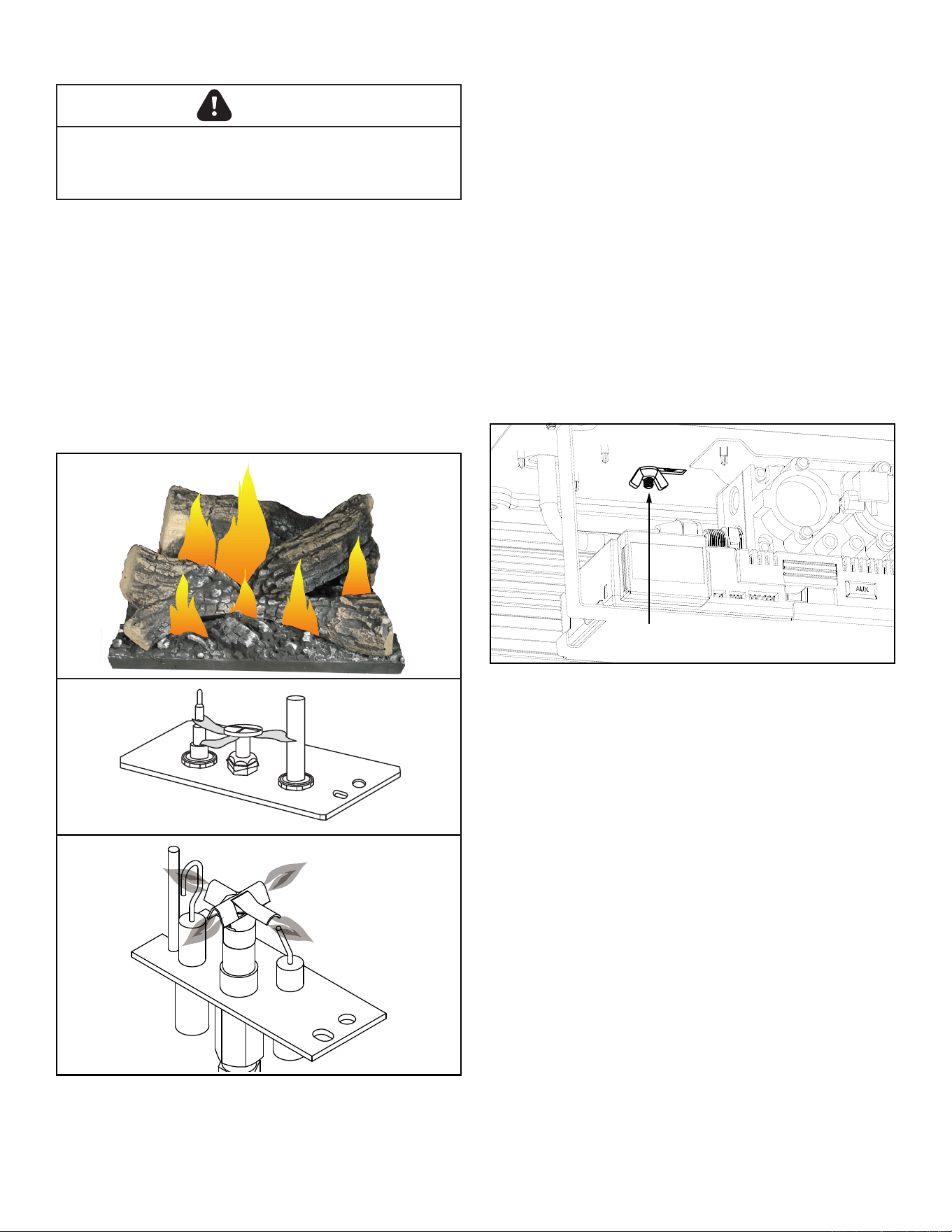
3939 3-90-30007467Vermont Castings • Stardance SDDVT Installation Manual_R40 • 09/25
N. Burner, Pilot & Control Compartment
Keep the control compartment, stones and burner areas
surrounding the stones clean by vacuuming or brushing at
least twice a year. Make sure the burner porting, pilot air
opening and burner air opening are free of obstructions at
all times.
Pilot Flame
The ames from the pilot should be visually checked as
soon as the heater is installed and periodically during normal
operation. The pilot ame must always be present when the
stove is in operation, Figure 4.6. The pilot ame has three
distinct ames, one engulng the sensor, one engulng the
thermopile, and the other reaching to the main burner.
WARNING
Turn o gas before servicing stove. It is recommended that
a qualied service technician perform these check-ups at
the beginning of each heating season
Figure 4.6 - Correct pilot and burner ame appearance.
RADVT MODELS
RADVT-IFT
LG500
Intrepid log flames
7/07
CO105d
Pilot flame
6/07 djt
Burner
Inspect area around the injector. Remove any lint or foreign
material with a brush or vacuum.
Burner Flame
The ames from the burner should be visually checked as
soon as the heater is installed and periodically during normal
operation. In normal operation, at full rate, and after operating
for about 15 to 30 minutes, the ame should be yellow.
NOTE:Thetypeofinstallation,ventsystemconguration,
andwindeectsmaycausetheamepatternstovary.
Air shutter
Air shutter settings should be adjusted by a qualied service
technician at the time of installation. The air shutter is set
at the factory for minimum vertical run. Adjusting air shutter
may be desired for longer vent runs. See Figure 4.7.
NOTICE: If sooting occurs, provide more air by opening the
air shutter.
Figure 4.7 - Air shutter.
Air Shutter
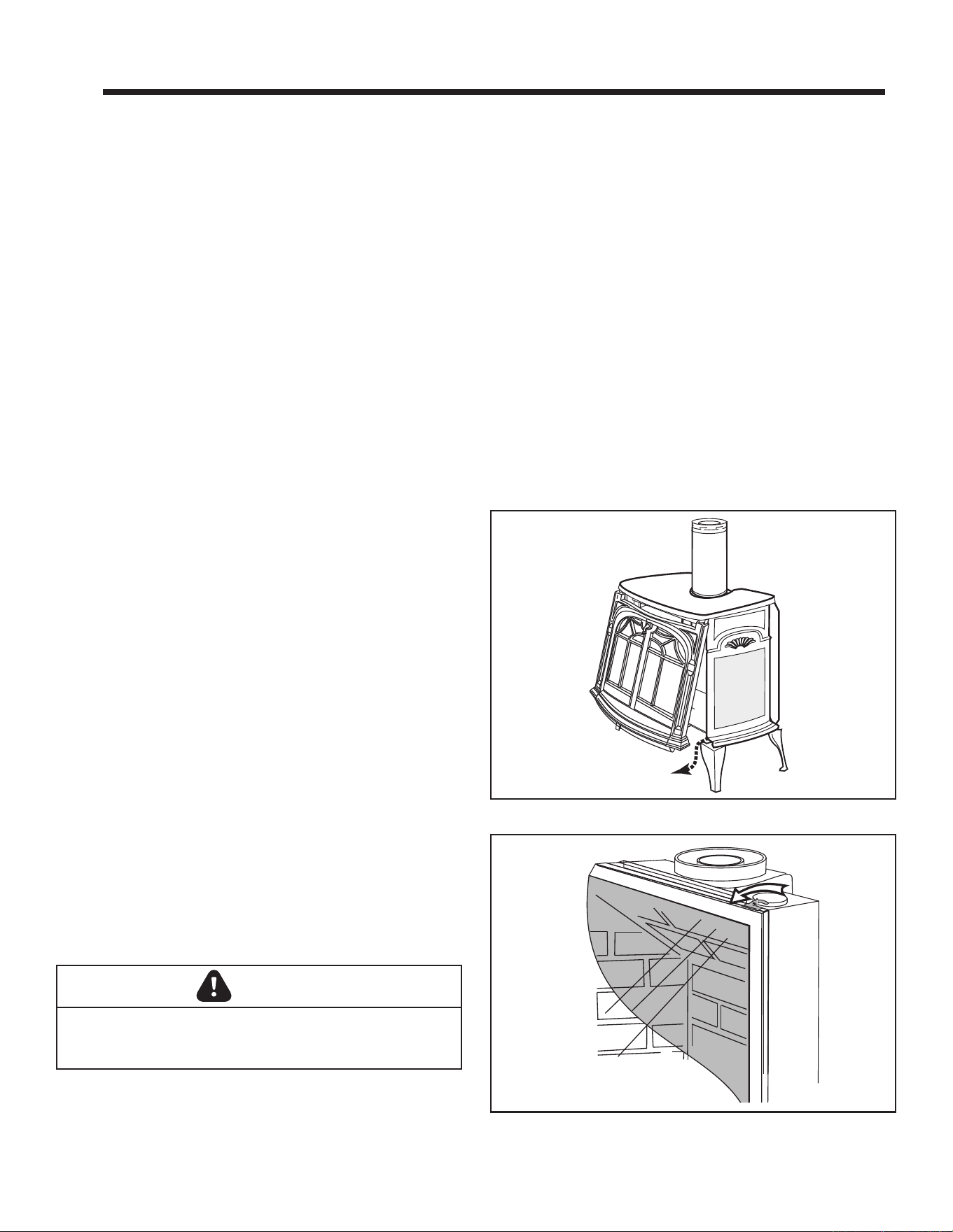
4040 3-90-30007467Vermont Castings • Stardance SDDVT Installation Manual_R40 • 09/25
Your Stardance Gas Heater will provide years of service with
minimal upkeep. The following procedures will help ensure
that your stove continues to function properly.
A. Annual System Inspection
Have the entire heater and venting system inspected annually
by a qualied gas technician. Replace any worn or broken
parts.
B.Logset&Burner/CleaningandInspection
Cleanliness is critical to the proper function of the heater.
The logset and burner must all be kept free of dust and
unobstructed by debris. Inspect these areas before each use
and clean as necessary.
1. Turn the burner OFF and let the heater cool completely
before cleaning.
2. Remove the safety barrier and lift the stove front up and
then swing the bottom out to disengage it from the heater
shell.
3. Carefully remove the glass and frame assembly and
place it out of the way on a at, padded surface such as
a counter protected by a towel.
4. Carefully inspect the Logs for damage. Contact your
local dealer if any damage is evident.
5. Use a soft bristled brush to sweep dust or debris from the
Logs, Pilot and Burner. Use care as the logs are fragile
and susceptible to damage.
6. Replace the glass panel and frame assembly.
7. Replace the stove front and safety barrier.
C. Care of Cast Iron
An occasional dusting with a dry rag will help keep the painted
surfaces looking new. Use high-temperature stove paints,
available through your local dealer, to touch-up areas as
needed. Clean areas to be painted with a wire brush and be
sure to cover the logs, burner and valve assembly, glass and
frame assembly. Apply the paint sparingly; two light coats of
paint will give better results than a single heavy coat.
Clean porcelain enamel surfaces with a soft, damp cloth.
Do not use abrasive cleaning agents. If necessary, use only
a cleaning agent formulated especially for use on porcelain
enamel surfaces.
D. Glass Cleaning and Replacement
It will be necessary to clean the glass periodically. During
start-up, condensation, which is normal, forms on the inside of
the glass and causes lint, dust and other airborne particles to
cling to the glass surface. Also initial paint curing may deposit
a slight lm on the glass. It is therefore recommended that
the glass be cleaned two or three times with a non-ammonia
household cleaner and warm water (we recommend gas
stove glass cleaner). Allow the glass to cool completely before
attempting to clean. To access the glass, remove the front and
glass frame, Figures 5.1 and 5.2. After that the glass should
be cleaned two or three times during each heating season
depending on the circumstances present.
NOTE:Cleanglassafterrsttwoweeksofoperation.
Glass Replacement
Replace glass only with HHT approved parts. Refer to Section
7 “Service Parts List” for correct glass. Remove the front,
glass frame and glass panel, Figures 5.1 & 5.2. Use a razor
blade to separate the glass and gasket from the frame.
CAUTION
Turn the pilot o before painting. Allow the heater to cool
completely before painting.
5 5
Cleaning and Maintenance
Figure 5.1 - Remove the stove front.
ST474
Stardance
Remove Front
10/3/00
Figure 5.2 - Release the latches to remove the glass frame.
ST208
glass swivel latch
12/99
4141 3-90-30007467Vermont Castings • Stardance SDDVT Installation Manual_R40 • 09/25
E. Gasket Replacement
The Radiance Gas Heater uses a ‘tadpole’ type gasket to seal
between the glass panel and the frame. In time, this gasket
can become brittle and compressed and should be replaced.
New gasket is available from your dealer.
Shut o the gas supply and allow the stove to cool. Wear
safety goggles and a dust mask.
1. Remove the front, glass frame and glass panel, Figures
5.1 & 5.2. To remove the old gasket, use a razor blade
to separate the glass and gasket from the frame, and
to clean the glass of any remaining cement or bits of
gasket. Use a cold chisel if necessary.
2. Determine the correct length of gasket by laying it out
around the edge of the glass. Allow an extra 1 - 2” (25-
50mm). Mark the spot to be cut. Use a utility knife.
3. Starting on a long edge, remove about 6” of the
protective paper strip and apply the at adhesive face
of the gasket around the outside-facing edge of the
panel. Continue around the panel, applying about 6” at
a time and being careful to not stretch the material. Do
not overlap the gasket ends, Figure 5.3.
4. Apply a thin bead of high temperature silicone rubber
sealant along the inside corner of the glass frame, all
around the perimeter. Place the at gasketed side of
the glass panel back into the steel frame. Pinch the
rounded inside-facing gasket material to bulk it up.
5. Replace the glass frame and front panel as previously
described.
F. Inspect the Vent System Annually
Have the vent system inspected annually by a qualied
technician. Shut o the main gas supply before inspecting
the system. Both the inner exhaust pipe and the outer
combustion supply pipe must be checked to conrm that
they are unblocked and in good condition.
G. Check the Gas Flame Regularly
To ensure that the stove is operating properly, check the
ames periodically to conrm they match Figure 5.4. The
ames will be blue during the rst 15-20 minutes of operation,
and will gradually turn to yellow after that.
Do not use your stove if the ame pattern diers from that
shown here. Contact your Vermont Castings dealer or a
qualied technician for help.
ST179
glass gasket detail
11/99
Figure 5.3 - Wrap the gasket material around the outside edge of the glass.
LG500
Intrepid log flames
7/07
Figure 5.4 - Proper ame appearance
DANGER
HOT GLASS WILL
CAUSE BURNS.
DO NOT TOUCH GLASS
UNTIL COOLED.
NEVER ALLOW CHILDREN
TO TOUCH GLASS.
A barrier designed to reduce the risk of burns from
the hot viewing glass is provided with this
appliance and must be installed.
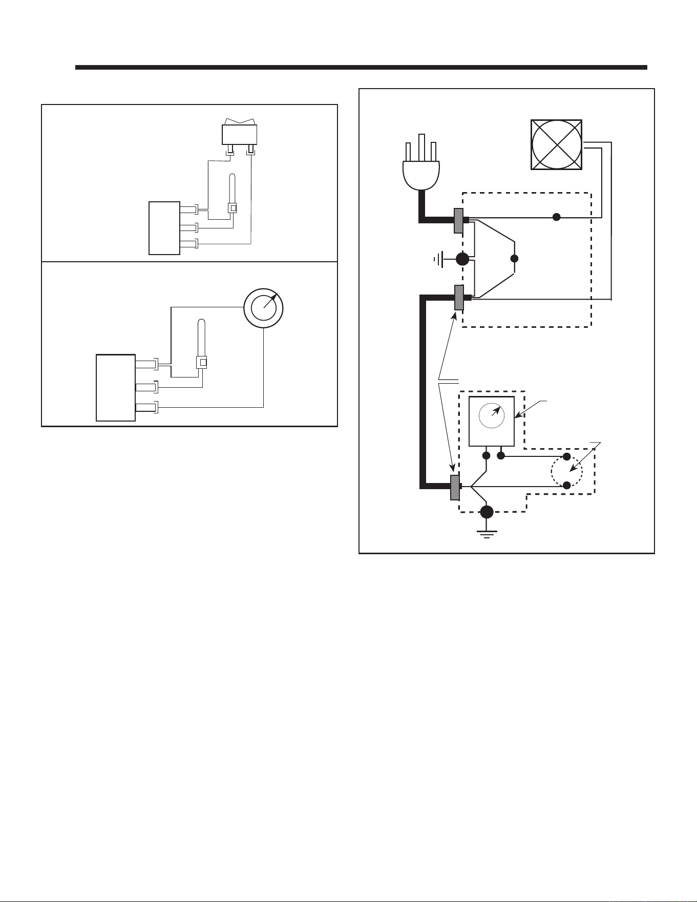
4242 3-90-30007467Vermont Castings • Stardance SDDVT Installation Manual_R40 • 09/25
NOTE: If any of the original wire, as supplied with the
appliance,mustbereplaced,it mustbereplacedwith
type SF-2, 200°C wire or its equivalent.
SDDVTModels(MillivoltOnly)
Figure 6.1 - On/o switch and optional thermostat circuit.
Optional Thermostat Wiring
On/OSwitchWiring
OFF
ON
Thermostat
(Optional)
Thermopile
Black
Black
Millivolt
Gas Valve
St124b
on/off/switch
wiring
1/11/00 djt
TP/TH
TP
TH
Thermostat
(Optional)
Thermopile
Black
Black
Millivolt
Gas Valve
St124c
Thermostat
wiring
1/11/00 djt
TP/TH
TP
TH
Optional Blower Kit Wiring Diagram
FAN JUNCTION BOX
FAN
POWER
CORD
Strain Relief
Chassis Ground
BLK
GRN
GRN
WHT
ON / OFF
Rheostat
Chassis
Ground
RHEOSTAT / SNAPSTAT
BOX
Snapstat
BLK
BLK
BLK
BLK
BLK
WHT
ST153
rdv connections diag.
10/99
Figure 6.2 - Fan circuit.
6 6
Wiring Diagrams
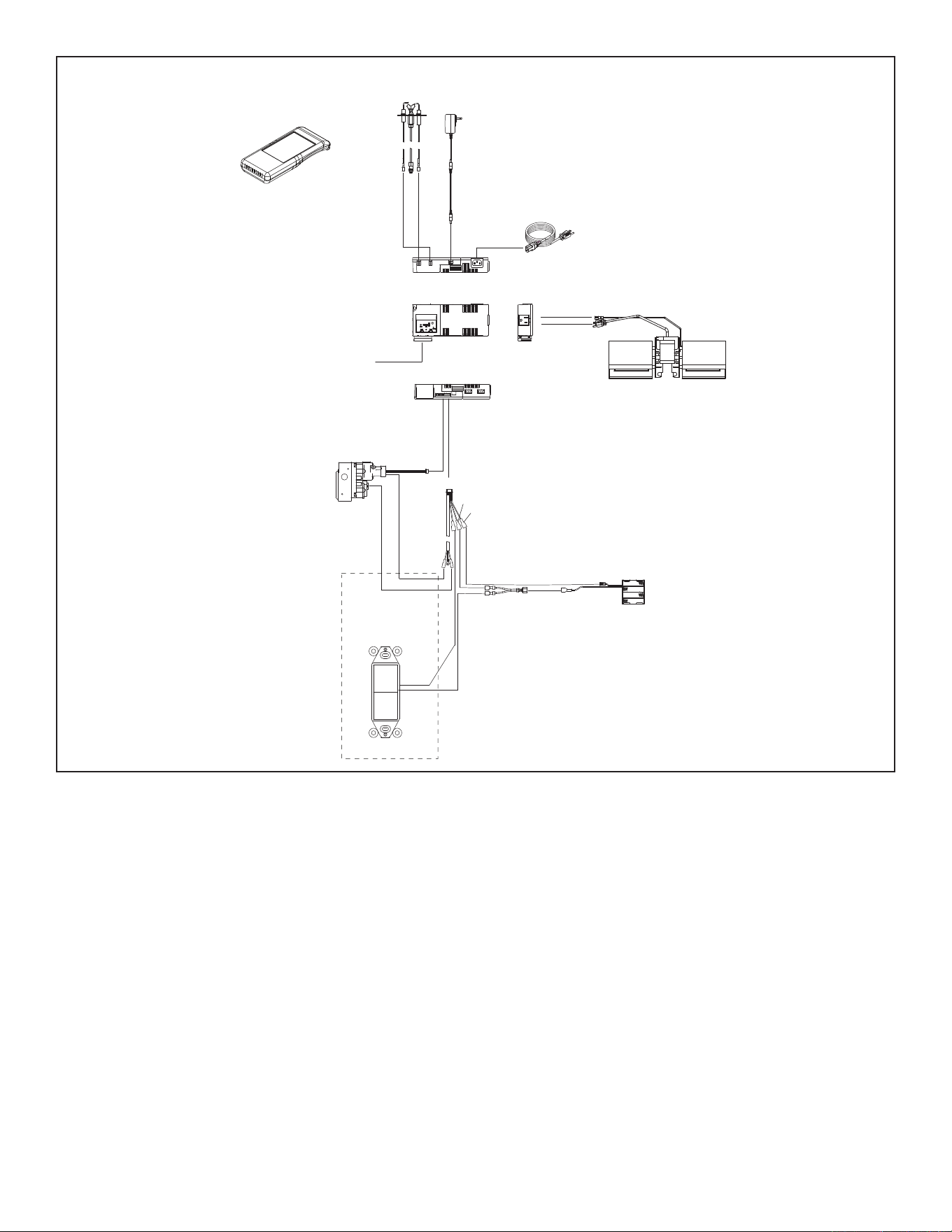
4343 3-90-30007467Vermont Castings • Stardance SDDVT Installation Manual_R40 • 09/25
Figure 6.3 - SDDVT-IFT Wiring Diagram
FLAME
SENSE
IGNITER
RF MODULE
6 PIN
BRN
ORANGE
(PILOT)
GREEN
(MAIN)
IFT-RC400
REMOTE
CONTROL
BLK
RED
ROCKER
SWITCH
SPLITTER
BLK
RED
BLK
TO JUNCTION
BOX 110-120 VAC
I
S
6V DC
BATTERY PACK
BLK
3 PRONG 110VAC
GROUND
FAN
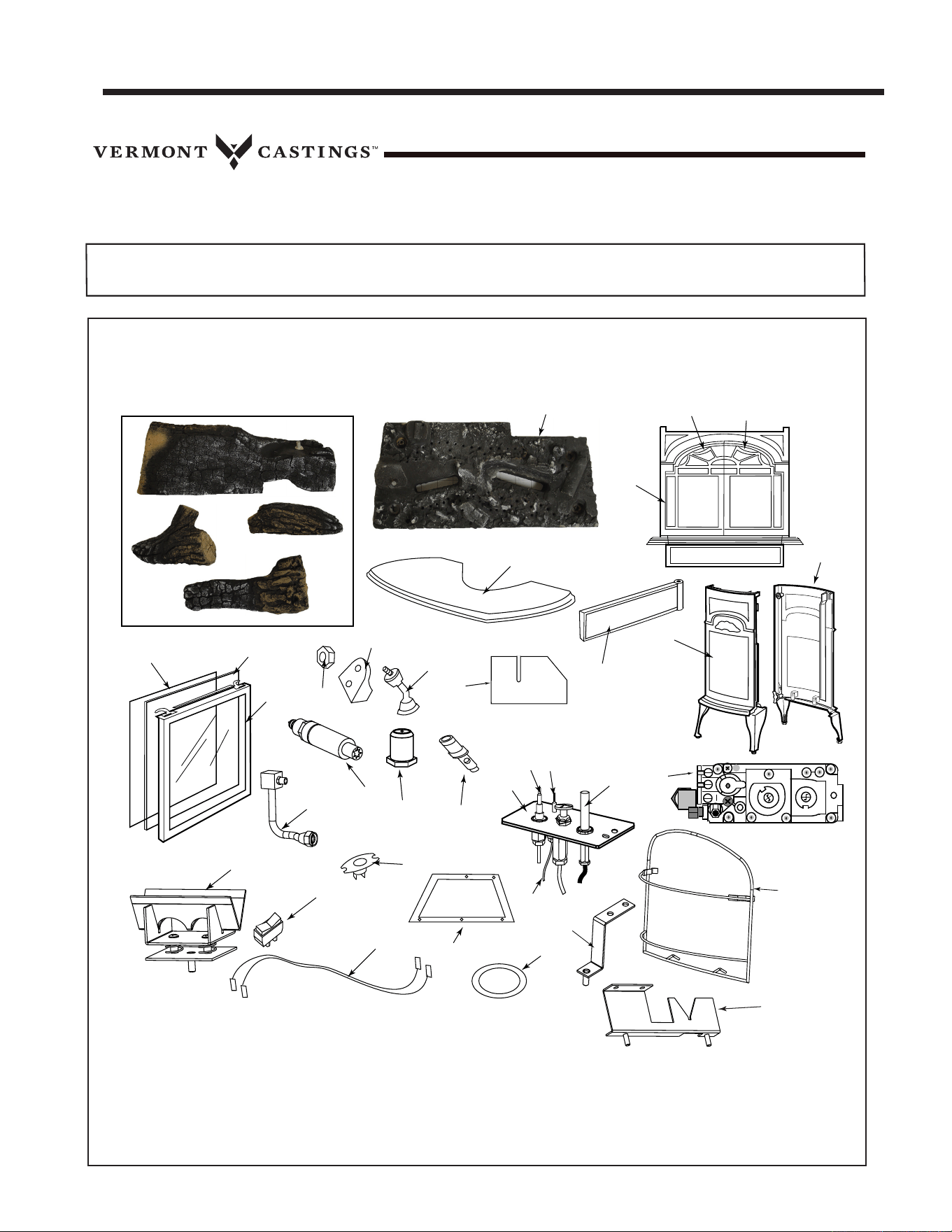
4444 3-90-30007467Vermont Castings • Stardance SDDVT Installation Manual_R40 • 09/25
Service Parts
STARDANCE DV
Beginning Manufacturing Date: NA
Ending Manufacturing Date: Active
Direct Vent Gas Heater
Part number list on following page.
01/24
SDDVTCBSB (Classic Black)
SDDVTBSSB (Biscuit) - Ending Manufacturing Date: Nov 2021
SDDVTBMSB (Majolica Brown)
SDDVTBDSB (Bordeaux)
1.1
1.2
1.3
12
11
10
28
30
24
31
9
3
4
6
5
18
19
20
21
22
29
26
32
7
8
17
25
1.4
1
2
16
27
13
14
15
23
34
33
35
With Standing Pilot Ignition
7 7
Service Parts List
4545 3-90-30007467Vermont Castings • Stardance SDDVT Installation Manual_R40 • 09/25
Service Parts
STARDANCE DV
Beginning Manufacturing Date: NA
Ending Manufacturing Date: Active
IMPORTANT: THIS IS DATED INFORMATION. Parts must be ordered from a dealer or distributor.
Hearth and Home Technologies does not sell directly to consumers. Provide model number
and serial number when requesting service parts from your dealer or distributor.
Stocked
at Depot
ITEM DESCRIPTION COMMENTS PART NUMBER
1
Log Set, Complete
SRV20012551 Y
1.1 Log, Rear
No longer
available, Must
order complete
assembly
20012546
1.2
Log, Right
20012548
1.3 Log, Left
20012547
1.4
Log, Top
20012915
2 Burner Assembly
20012492 Y
3 Top
Classic Black
30001276A
Biscuit
30003305A
Bordeaux
30006752A
Brown Majolica
30004897A
4 Front, Operable Door
Classic Black
30001496A
Biscuit
30003302A
Bordeaux
30006753A
Brown Majolica
30004899A
5
Door, Right (Use Magnet)
(Pre 7/2007 units must order Left and Rigth together)
Classic Black
30004081A
Biscuit
30004089A
Bordeaux
30006754A
Brown Majolica
30004900A
6
Door, Left (Use Magnet)
(Pre 7/2007 units must order Left and Rigth together)
Classic Black
30004082A
Biscuit
30004090A
Bordeaux
30006755A
Brown Majolica
30004901A
7 End, Left
Classic Black
30001280A
Biscuit
30003300A
Bordeaux
30006750A
Brown Majolica
30004895A
8 End, Right
Classic Black
30001279A
Biscuit
30003301A
Bordeaux
30006751A
Brown Majolica
30004896A
9 Door, Control
1301087A
10 Glass Frame Assembly
30000127 Y
11 Glass
1601691 Y
12 Gasket, Glass (Medium Knit)
1203702K
13
Nut, Hex Jam 3/8-16 TOPLK-Z Pkg of 10 1203290-10
14 Pawl Assembly, Ash Door
30002362
15 Front Steel Handle/Shaft - NI/VER
30002717 Y
16 Restrictor Plate
20013026
Additional service parts on following page
4646 3-90-30007467Vermont Castings • Stardance SDDVT Installation Manual_R40 • 09/25
Service Parts
STARDANCE DV
Beginning Manufacturing Date: NA
Ending Manufacturing Date: Active
IMPORTANT: THIS IS DATED INFORMATION. Parts must be ordered from a dealer or distributor.
Hearth and Home Technologies does not sell directly to consumers. Provide model number
and serial number when requesting service parts from your dealer or distributor.
Stocked
at Depot
ITEM DESCRIPTION COMMENTS PART NUMBER
17 Valve, Nova SIT 820.852 RN 20012218
Y
18 Pilot Assembly 3 Way
N/DV RN 0.199.706 SRV10002264
Y
N/DV RP 0.199.703 SRV10002265
Y
19 Thermocouple, 24” SRV24D0808
Y
20 Electrode Ignitor w/Cable SIT24 10001297
21 Thermopile, 18” RS SRV26D0566
Y
22 Tubing Pilot w/Fittings 1/8 x 24” 26D0665
Y
23 Pilot Orice, Top Convertible
NG, #62 37D0022
LP, #35 SRV200-2630
Y
24 Orice Hood
NG, 2.4 mm 4604-316
LP, 1.45 mm 20308650
25 Ignitor Piezo w/Nut SIT 057958A
Y
26 Manifold Assembly 20012553
Y
27 Air Shutter Assembly 20012517
28 Trim On/O Switch 30000874
Y
29 Sensor1450 CMG-8184-0032 Only for FSDHAG SRV10002013
Y
30 Wiring Harness 10002582
Y
31 Gasket, Base Pan 20002282
Y
32 Gasket HE Door 1203687A
Y
33 Tie Bracket Assembly 20012514
34 Safety Screen Barrier 30007254
Y
35 Right Burner Support Assembly 20012512
Fan Kit BK-VC
Flexline Black
20H1011
Handle Package w/Screw Wood 30004175K
Y
Switch Bracket 53821K
Starter Pipe 20307738K
Rear Shroud 20003802
Fiberglass Gasket, 1/4” 834-1460
Y
Magnet, Door (Use super glue/silicone to attach) 30004112
Touch-Up Paint
Classic Black 3-42-19905
Bordeaux
0001341
Biscuit
0001277
Majolica
1-00-0014
Control Plate Assembly (Burner, Valve, Pilot) 20012493
Finish Bag SRV30007263
Conversion Kits
Conversion Kit, NG to LP LPK-SDDVT-SP
Y
Conversion Kit, LP to NG 4604-012
Y
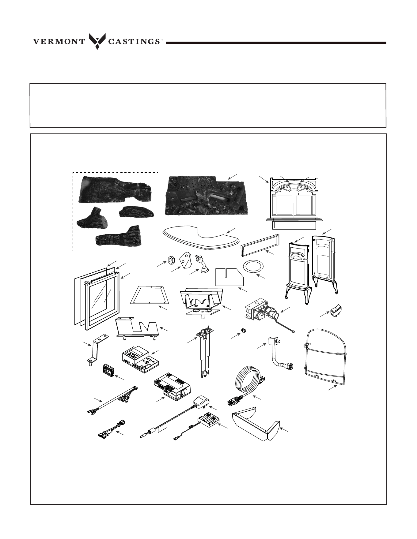
4747 3-90-30007467Vermont Castings • Stardance SDDVT Installation Manual_R40 • 09/25
Service Parts
STARDANCE IFT
Beginning Manufacturing Date: Feb 2019
Ending Manufacturing Date: Active
Direct Vent Gas Heater w/IFT Controls
Part number list on following page.
SDDVT-IFT-CB (Classic Black) SDDVT-IFT-BM (Majolica Brown)
SDDVT-IFT-BD (Bordeaux) SDDVT-IFT-BS (Biscuit) - Ending Manufacturing Date: Dec 2021
1.1
1.2
1.3
1.4
1
36
22
29
28
32
31
27
33
26
25
30
2
10
11
12
8
9
6
7
5
4
3
18
19
17
15
14
13
16
24
23
20
21
34
35
4848 3-90-30007467Vermont Castings • Stardance SDDVT Installation Manual_R40 • 09/25
Service Parts
STARDANCE IFT
Beginning Manufacturing Date: Feb 2019
Ending Manufacturing Date: Active
IMPORTANT: THIS IS DATED INFORMATION. Parts must be ordered from a dealer or distributor. Hearth and Home
Technologies does not sell directly to consumers. Provide model number and serial number when requesting service
parts from your dealer or distributor.
Stocked
at Depot
ITEM DESCRIPTION COMMENTS PART NUMBER
1
Log Set, Complete
SRV20012551 Y
1.1 Log, Rear
No longer
available, Must
order complete
assembly
20012546
1.2
Log, Right
20012548
1.3 Log, Left
20012547
1.4
Log, Top
20012915
2 Burner Assembly
20012492 Y
3 Front, Operable Door
Classic Black
30001496A
Biscuit
30003302A
Bordeaux
30006753A
Brown Majolica
30004899A
4 Door, Left (Use Magnet)
Classic Black
30004082A
Biscuit
30004090A
Bordeaux
30006755A
Brown Majolica
30004901A
5 Door, Right (Use Magnet)
Classic Black
30004081A
Biscuit
30004089A
Bordeaux
30006754A
Brown Majolica
30004900A
6 End, Right
Classic Black
30001279A
Biscuit
30003301A
Bordeaux
30006751A
Brown Majolica
30004896A
7 End, Left
Classic Black
30001280A
Biscuit
30003300A
Bordeaux
30006750A
Brown Majolica
30004895A
8 Door, Control
1301087A
9 To p
Classic Black
30001276A
Biscuit
30003305A
Bordeaux
30006752A
Brown Majolica
30004897A
10 Front Steel Handle/Shaft - NI/VER
30002717 Y
11 Pawl Assembly, Ash Door
30002362
12
Nut, Hex Jam 3/8-16 TOPLK-Z Pkg of 10 1203290-10
13 Glass Frame Assembly
30000127 Y
14 Gasket, Glass (Medium Knit)
1203702K
15 Glass
1601691 Y
Additional service parts on following page
4949 3-90-30007467Vermont Castings • Stardance SDDVT Installation Manual_R40 • 09/25
Service Parts
STARDANCE IFT
Beginning Manufacturing Date: Feb 2019
Ending Manufacturing Date: Active
IMPORTANT: THIS IS DATED INFORMATION. Parts must be ordered from a dealer or distributor. Hearth and Home
Technologies does not sell directly to consumers. Provide model number and serial number when requesting service
parts from your dealer or distributor.
Stocked
at Depot
ITEM DESCRIPTION COMMENTS PART NUMBER
16 Tie Bracket Assembly 20012514
17 Right Burner Support Assembly 20012512
18 Gasket, Base Pan 20002282
Y
19 Air Shutter Assembly 20012517
20 Restrictor Plate
20013026
21 Gasket HE Door 1203687A
Y
22 Valve Assembly
NG SRV2166-302
Y
Propane 2166-303
Y
23 Trim On/O Switch 30000874
Y
24 Manifold Assembly 20012553
Y
25 Orice Hood
NG 4604-316
Y
Propane 20308650
Y
26 Pilot Assembly NG SRV4602-300
Y
Pilot Orice
NG SRV582-880
Y
Propane SRV4602-301
Y
27 Control Module SRV2326-130
Y
28 Module, RF SRV2326-120
Y
29 Wiring Harness, 6 Pin SRV2326-132
Y
30 Jumper Wire SRV2187-198
Y
31 Module, AC SRV2326-150
Y
32 Transformer, 6 Volt Wall SRV2326-131
Y
33 Battery Pack** SRV2326-134
Y
34 Cable, Module AC SRV2326-152
Y
35 Front Cover SRV30007460
36 Safety Screen Barrier 30007254
Y
Magnet, Door
Use super glue/
Silicone to attach
30004112
Power Cord
SRV30005079 Y
Rear Shroud Assembly SRV30007464
RC400 Remote SRV2326-110
Y
Switch Bracket 53821K
Starter Pipe 20307738K
Finish Bag SRV30007263
**Fuse for battery pack can be sourced locally, not a warranty item. Specs are 250v, 3A fuse, 3/4” long
Additional service parts on following page
5050 3-90-30007467Vermont Castings • Stardance SDDVT Installation Manual_R40 • 09/25
Service Parts
STARDANCE IFT
Beginning Manufacturing Date: Feb 2019
Ending Manufacturing Date: Active
IMPORTANT: THIS IS DATED INFORMATION. Parts must be ordered from a dealer or distributor. Hearth and Home
Technologies does not sell directly to consumers. Provide model number and serial number when requesting service
parts from your dealer or distributor.
Stocked
at Depot
ITEM DESCRIPTION COMMENTS PART NUMBER
Blower Assembly GFK-160A
Touch-Up Paint
Classic Black 3-42-19905
Bordeaux
0001341
Biscuit
0001277
Majolica
1-00-0014
Warming Shelf Kit
Classic Black 0002702
Bordeaux 0002686
Biscuit 0002684
Majolica 0002681
Shelf
Classic Black 1301133A
Bordeaux SRV30006758
Biscuit SRV30003227
Majolica SRV30004853
Shelf Bracket
Classic Black 1301132A
Bordeaux SRV30006757
Biscuit SRV30003226
Majolica SRV30004852
Shelf Clip Qty 2 req 1409035
Hardware Pack 30007019K
Flexline Black
SRV20H1011 Y
Conversion Kits
Conversion Kit
NG to Propane
LPK-SDDVT-IFT
Y
Propane to NG
SRV30007469
Y
Regulator
NG
NGK-DXV-50
Y
Propane
SRVLPK-DXV-50
Y

5151 3-90-30007467Vermont Castings • Stardance SDDVT Installation Manual_R40 • 09/25
Fan Kit - SDDVT Series
The fan helps distribute heated air from within the rebox out
into the room. The fan is controlled by a snapstat that turns
power on and o as the rebox temperature rises above
and falls below a preset temperature. A rheostat provides
for variable fan speeds. Used with standard millivolt models.
Remote Controls - SDDVT
The remote control allows you to turn the heater on or o
from anywhere in the room. Refer to Page 40 for wiring
diagrams. These remote controls are for use with standard
millivolt models.
ON/OFFRemotes ON/OFFThermostatRemote
RCB,RCMT TSST, RCST
Warming Shelf
Warming shelves add versatility to your stove; they can be
used to keep foods warm at mealtime.
Model Color
1560 Classic Black
1553 Brown Majolica
1555 Biscuit
1571 Bordeaux
Shelf Installation
1. Attach the shelf loosely to the stove, leaving the screws
loose enough to allow nal adjustments.
2. Position the shelf and adjust the brackets so the shelf
ts correctly.
3. Tighten the screws.
Refer to the instructions included with each warming shelf
for complete installation procedures.
8 8
Optional Accessories
5252 3-90-30007467Vermont Castings • Stardance SDDVT Installation Manual_R40 • 09/25
Hearth & Home Technologies LLC
LIMITED WARRANTY
Hearth & Home Technologies LLC (“HHT”) extends the following warranty for HHT gas, wood, pellet and electric hearth appliances
(each a “Product” and collecvely, the “Product(s)”) and certain component parts set forth in the table below (“Component Part(s)”)
that are purchased from a HHT authorized dealer or distributor.
WARRANTY COVERAGE:
HHT warrants that the Products and their Component Parts will be free from defects in materials and workmanship for the applicable
period of Warranty coverage set forth in the table below (“Warranty Period”). If a Product or Component Parts are found to be
defecve in materials or workmanship during the applicable Warranty Period, HHT will, at our discreon, repair the applicable
Component Part(s), replace the applicable Component Part(s), or refund the purchase price of the applicable Product(s). The maximum
amount recoverable under this Warranty is limited to the purchase price of the Product. This Warranty is transferable from the original
purchaser to subsequent owners, but the Warranty Period will not be extended in duraon or expanded in coverage for any such
transfer. This Warranty is subject to condions, exclusions, and limitaons as described below.
WARRANTY PERIOD:
Warranty coverage begins at the date of installaon. In the case of new home construcons, Warranty coverage begins six months aer
invoice of the nal sale of the Product(s) by an independent, authorized HHT dealer or distributor. However, the Warranty coverage
shall commence no later than 24 months following the date of Product shipment from HHT, regardless of the installaon or purchase
date.
Page 1 of 2
4021-645N 12/23
Component
Parts
Labor Gas Pellet Wood Electric Component Parts Covered by this Warranty
X
All parts except as covered by Warranty Conditions, Warranty Exclusions, and Warranty
Limitations listed
XX
Glass, Electrical components limited to heating element/igniters, Top feed auger assembly,
Blowers, Junction Box, Remotes/Wall switches, linear actuator, power cord, vacuum switch,
snap disc, wire harnesses and thermocouple
X
Electrical components limited to modules, remotes/wall switches, valves, pilots, blowers,
junction boxes, wire harnesses, transformers and lights (excluding light bulbs)
XX
Cement Refractory Panels, Glass Liner Panels
X
Firepots, burnpots, Harman mechanical feeders
XX
Catalysts, Vented and Vent Free burners and logs
10 years 1 year
X
Burners, logs and metal/fiber refractory components of HHT manufactured fireplaces or stoves,
venting due to poor workmanship
10 years
3 years
XX
Castings, Medallions & Baffles, FlexBurn® System (engine, inner cover, access cover and
fireback), Firebox and heat exchanger, HHT Chimney & Terminations, Manifolds
20 years 3 years X Firebox and heat exchanger
1 Year
None
XXXX
All purchased replacement parts and optional accessories
3 years
5 years
All purchased replacement parts and optional accessories
2 Years
Warranty Period HHT Manufactured Appliances and Venting
All parts including handles, external enameled components and other material except as
covered by Warranty Conditions, Warranty Exclusions, and Warranty Limitations listed
1 Year XXX
9 9
Warranty Policy

5353 3-90-30007467Vermont Castings • Stardance SDDVT Installation Manual_R40 • 09/25
WARRANTY CONDITIONS:
• Because HHT cannot control the quality of any Products sold by unauthorized sellers, this Warranty only covers Products that are
purchased through an HHT authorized dealer or distributor unless otherwise prohibited by law; a list of HHT authorized dealers
is available on the HHT branded websites.
• This Warranty is only valid while the applicable Product remains at the site of original installaon.
• This Warranty is only valid in the country in which the HHT authorized dealer or distributor that sold the applicable Product is
authorized to sell applicable Product.
• Contact your installing distributor or dealer for Warranty service. If the installing dealer or distributor is unable to provide
necessary parts, contact the nearest HHT authorized dealer or supplier. Addional service fees may apply if you are seeking
Warranty service from a dealer other than the dealer from whom you originally purchased the applicable Product.
• No HHT consumer should bear cost of warranty service or costs incurred while servicing warranty claims (i.e., travel, gas, or
mileage) when the service is performed within the terms of this Warranty. Check with your dealer or distributor in advance for
any costs to you when arranging a warranty call. Travel and shipping charges for parts are not covered by this Warranty.
WARRANTY EXCLUSIONS:
This Warranty does not cover the following:
• Changes in surface nishes as a result of normal use. As a heang appliance, some changes in color of interior and exterior surface
nishes may occur. This is not a aw and is not covered under the Warranty.
• Damage to printed, plated, or enameled surfaces caused by ngerprints, accidents, misuse, scratches, melted items or other
external sources and residues le on the plated surfaces from the use of abrasive cleaners or polishes.
• Repair or replacement of parts that are subject to normal wear and tear during the Warranty Period are not covered. These parts
include: paint, wood and pellet gaskets, rebricks, wood grates, ame guides, baeries and the discoloraon of glass.
• Minor expansion, contracon, or movement of certain parts causing noise. These condions are normal and complaints related to
this noise are not covered by this Warranty.
• Damages resulng from: (1) failure to install, operate, or maintain the applicable Product in accordance with the installaon
instrucons, operang instrucons, and lisng agent idencaon label furnished with the applicable Product; (2) failure to
install the applicable Product in accordance with local building codes; (3) shipping or improper handling; (4) improper operaon,
abuse, misuse, connued operaon with damaged, corroded or failed components, accident, or improperly/incorrectly performed
repairs; (5) environmental condions, inadequate venlaon, negave pressure, or draing caused by ghtly sealed construcons,
insucient make-up air supply, or handling devices such as exhaust fans or forced air furnaces or other such causes; (6) use of fuels
other than those specied in the operaon instrucons; (7) installaon or use of components not supplied with the applicable
Product or any other components not expressly authorized and approved by HHT; (8) modicaon of the appliance not expressly
authorized and approved by HHT in wring; and/or (9) interrupons or uctuaons of electrical power supply to the applicable
Product.
• Non-HHT venng components, hearth connecons or other accessories used in conjuncon with the applicable Product.
• Any part of a pre-exisng replace system in which an insert or a decorave gas applicable Product is installed.
• HHT’s obligaon under this Warranty does not extend to the Product’s capability to heat the desired space. Informaon is provided
to assist the consumer and the dealer in selecng the proper Product for the applicaon. Consideraon must be given to the
Product locaon and conguraon, environmental condions, insulaon and air ghtness of the structure.
This warranty is void if:
• The applicable Product has been over-red, operated in atmospheres contaminated by chlorine, uorine, or other damaging
chemicals. Over-ring can be idened by, but not limited to, warped plates or tubes, deformaon/warping of interior cast iron
structure or components, rust colored cast iron, bubbling, cracking and discoloraon of steel or enamel nishes.
• The applicable Product is subjected to prolonged periods of dampness or condensaon.
• There is any damage to the applicable Product due to water or weather damage which is the result of, but not limited to, improper
chimney or venng installaon.
LIMITATIONS OF REMEDIES AND LIABILITY:
• EXCEPT TO THE EXTENT PROVIDED BY LAW, HHT MAKES NO EXPRESS WARRANTIES OTHER THAN THE WARRANTY SPECIFIED
HEREIN. The owner’s exclusive remedy and HHT’s sole obligaon under this Warranty or in contract, tort or otherwise, shall
be limited to, at HHT’s sole opon, replacement of the Component Part(s), repair of the Component Part(s), or refund of the
original purchase price of the applicable Product(s). In no event will HHT be liable for any incidental or consequenal damages
caused by defects in the applicable Product. Some States do not allow the exclusion or limitaon of incidental or consequenal
damages, so the above limitaon or exclusion may not apply to you. This Warranty gives you specic legal rights and you may
also have other rights which vary from State to State. THE DURATION OF ANY IMPLIED WARRANTY IS LIMITED TO DURATION OF
THE EXPRESSED WARRANTY SPECIFIED ABOVE FOR THE APPLICABLE PRODUCT. Some States do not allow limitaons on how long
an implied warranty lasts, so the above limitaon may not apply to you.
Page 2 of 2
4021-645N 12/23
5454 3-90-30007467Vermont Castings • Stardance SDDVT Installation Manual_R40 • 09/25
Based on CSA P.4.1-2015
EFFICIENCY RATINGS
MODEL
ENERGUIDE RATINGS
STOVE EFFICIENCY
PERCENTAGE
D.O.E.
(AFUEPERCENTAGE)
SDDVT Series 58.4 66.5
SDDVT-IFT Series 63.3 66.5
352 Mountain House Road • Halifax, PA 17032
www.forgename.com