
54-38-1603
58-01-1371991D6086-20
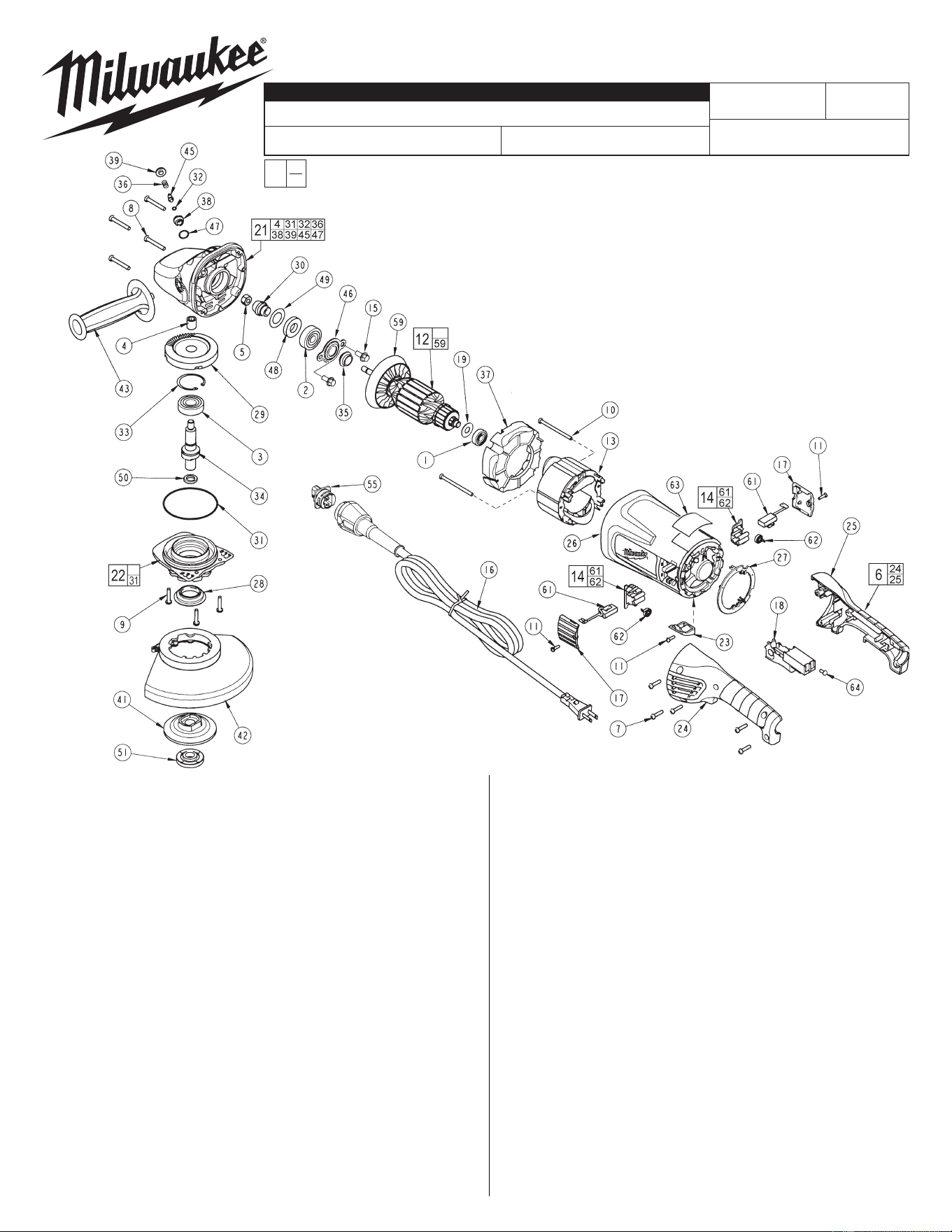
FIG. PART NO. DESCRIPTION OF PART NO REQ.
1 02-04-1675 Ball Bearing (1)
2 02-04-1680 Ball Bearing (1)
3 02-04-1745 Ball Bearing (1)
4 02-50-2429 Needle Bearing (1)
5 06-55-2455 Hex Nut (1)
6 14-34-0570 Handle Kit (1)
7 06-82-0055 8-16 Torx Plastite Screw T-20 (5)
8 06-82-0060 10-14 Torx Plastite Screw T-25 (4)
9 06-82-0065 10-32 x 1 Pan Hd. Taptite T-25 Screw (3)
10 06-82-0070 8-16 Torx Plastite Screw T-15 (2)
11 06-82-7240 6-19 x 1/2 Slt. Pan Hd. Plast. T-15 (3)
12 16-70-0132 Armature Assembly (1)
13 18-70-1130 Field (1)
14 22-20-0120 Brush Holder Assembly (2)
15 06-75-0510 1/4-20 x .62 Hex Flange Screw (2)
16 48-76-5110 Quik-Lok Cord Set (1)
17 23-44-0255 Brush Cover (2)
18 23-66-2720 Switch (1)
19 45-06-0830 Bearing Seal (1)
21 28-14-1131 Gearcase Assembly (1)
22 28-53-0151 Spindle Hub Assembly (1)
23 31-15-0166 Cover (1)
24 --------------- Left Hand Handle Halve (1)
25 --------------- Right Hand Handle Halve (1)
26 31-50-1785 Motor Housing (1)
27 31-53-0160 Plug (1)
28 31-55-0150 Bearing Shield (1)
29 32-05-1505 Gear (1)
30 32-60-1505 Pinion Gear (1)
31 34-40-0505 O-Ring (1)
32 34-40-4300 O-Ring (1)
9" GRINDER
REVISED BULLETIN
SERVICE PARTS LIST
BULLETIN NO.
WIRING INSTRUCTION
DATE
SPECIFY CATALOG NO. AND SERIAL NO. WHEN ORDERING PARTS
SERIAL
NUMBER
CATALOG NO.
MILWAUKEE ELECTRIC TOOL CORPORATION
13135 W. LISBON RD., BROOKFIELD, WI 53005
Drwg. 4
FIG. PART NO. DESCRIPTION OF PART NO REQ.
33 34-80-2960 Retaining Ring (1)
34 38-50-2500 Spindle Shaft (1)
35 31-55-0290 Dust Shield (1)
36 40-50-1550 Compression Spring (1)
37 42-14-0425 Baffle (1)
38 42-30-0150 Lock Body (1)
39 42-42-0290 Button (1)
41 43-34-0825 5/8 Back Flange (1)
42 49-12-0020 Guard Assembly (Type 27) (1)
43 43-62-1265 Side Handle (1)
45 44-60-1650 Lock Pin (1)
46 44-86-0040 Bearing Retainer (1)
47 34-40-4555 O-Ring (1)
48 45-06-0710 Seal (1)
49 45-88-7880 Shim Washer (1)
50 45-88-8466 5/8-11 Spindle Washer (1)
51 49-05-0051 Flange Nut (1)
FIG. LUBRICATION:
21 1.25 oz. (35 grams) of Type "Y" grease, No. 49-08-5270 in
main gear cavity of gearcase.
29,30 "Y" grease must be applied to all gear teeth.
31,32 Lightly coat o-rings with "Y" grease prior to installation.
FIG. NOTES:
4,21 Press needle bearing flush ±.02 to gearcase boss face.
33 Bevel side of retaining ring away from bearing face.
EXAMPLE:
Component Parts (Small #)
Are Included When Ordering
The Assembly (Large #).
0
00
FIG. PART NO. DESCRIPTION OF PART NO REQ.
55 22-56-1050 Blade Housing Assembly (1)
59 22-84-0540 Fan Assembly (1)
61 22-18-0126 Carbon Brush Assembly (2)
62 --------------- Brush Spring (2)
63 12-99-5006 Nameplate Blank (1)
64 05-78-0305 Switch Screw (4)
23-94-9300 Leadwire Assembly (1)
23-94-9305 Leadwire Assembly (1)
23-94-9310 Leadwire Assembly (1)
23-94-9315 Leadwire Assembly (1)
49-96-7205 Spanner Wrench (1)
FIG. NOTES:
5 Torque to 140 in.-lbs.
7,10 Torque to 20 in.-lbs.
8 Torque to 30 in.-lbs.
9 Torque to 35 in.-lbs.
15 Torque to 65-75 in.-lbs.
64 Torque to 4 in.-lbs.
54-38-1602
=Part number change
from previous service
parts list.
Aug. 2007