

INSTRUCTION MANUAL
Gas Powered Brush Cutter & String Trimmer
Model #AM4532


3
CONTENTS
CONTENTS ..................................................................................................................................................3
TECHNICAL DATA ....................................................................................................................................3
INTRODUCTION ........................................................................................................................................ 4
SAFETY INFORMATION ...........................................................................................................................4
GENERAL SAFETY RULES ...................................................................................................................... 5
KNOWING YOUR BRUSH CUTTER&STRING TRIMMER ................................................................... 9
ASSEMBLY INSTRUCTION ....................................................................................................................10
OPERATING INSTRUCTION .................................................................................................................. 13
MAINTENANCE ....................................................................................................................................... 16
TROUBLESHOOTING ..............................................................................................................................18
EXPLODED VIEW AND PARTS LIST ....................................................................................................20
WARRANTY ..............................................................................................................................................26
TECHNICAL DATA
2-Cycle Gas 2 in 1 Brush Cutter &String Trimmer
Model#
AM4532
Engine type: Air-cooled,2 cycle,vertical piston valve,gasoline engine
Displacement: 25.4 cc
Fuel used: Unleaded gasoline mixed with lubricating oil (ratio of 50:1)
Fuel tank capacity: 18.6 fl.oz
Blade size: 10 inch
Trimmer line diameter: 0.095"
Cutting path diameter: 16"
Length of main pipe section: 59 inch
Length of drive shaft section: 60 inch
Package dimensions (L x W x H): 43.3 x 10.2 x10.4 in.
Net weight: 18.7 lb.

4
INTRODUCTION
Thank You for purchasing your Amerisun Product. This manual provides information regarding the
safe operation and maintenance of this product. Every effort has been made to ensure accuracy of the
information found in this manual. Amerisun reserves the right to change this product and specifications
at any time without prior notice.
Please keep this manual available to all users during the entire life of the product.
This manual contains special messages to bring attention to potential safety concerns, product
damage as well as helpful operating and servicing information. Please read all the information
carefully to avoid injury and machine damage.
QUESTIONS? PROBLEMS?
Please contact our Customer Service Department with any questions and/or comments, either by Email:
help solve any issues that you might encounter.
NOTICE REGARDING EMISSIONS
Engines that are certified to comply with U.S. EPA emission regulations for SORE (Small Off Road
Equipment), are certified to operate on regular unleaded gasoline, and may include the following
emission control systems: (EM) Engine Modifications and (TWC) Three-Way Catalyst (if so equipped).
SAFETY INFORMATION
Before operating this product, read and observe all warnings, cautions, and instructions on the product
and in this Owner’s Manual.
NOTE: The following safety information is not meant to cover all possible conditions and situations
that may occur. Read the entire Owner’s Manual for safety and operating instructions. Failure to follow
instructions and safety information could result in serious injury or death.
This safety alert symbol is used to identify safety information about hazards that can result in personal
injury.
A signal word (DANGER, WARNING, or CAUTION) is used with the alert symbol to
indicate the likelihood and the potential severity of injury. In addition, a hazard symbol may
be used to represent the type of hazard.
DANGER: Indicates a hazard, which, if not avoided, will result in death or serious injury.
WARNING: Indicates a hazard, which, if not avoided, could result in death or serious injury.
CAUTION: Indicates a hazard, which, if not avoided, might result in minor or moderate injury.
CAUTION: When used without the alert symbol, indicates a situation that could result in damage to
the engine.

5
GENERAL SAFETY RULES
WARNING: This unit can cause serious injury including loss of limb(s) or blindness to the
operator and others. The warnings and safety instructions in this manual must be followed to
provide reasonable safety and efficiency in using the unit.
Operator Safety
Always wear safety glasses or similar eye protection when operating, or performing maintenance on
your unit. We recommend eye protection that is ANSI Z87 certified for impact resistance.
Never allow children to operate this unit.
Use appropriate hearing protection.
Always wear long pants from a sturdy fabric, long sleeves, boots and gloves. Wearing safety leg
guards is recommended. Dress appropriate to the terrain that you will be clearing.
Being fully covered will also help to protect you from debris and/or pieces of toxic plants thrown by
the spinning line/blade. A face or dust mask if recommended of the operation in dry conditions.
It is recommended to wear foot protection with a reinforced toe. Never attempt to use this product
while barefoot or in sandals.
Secure longer hair to above the shoulders. Secure or remove loosely hanging clothing, jewelry, ties,
straps, tassels, etc. They can become entangled and caught within the moving parts.
Do not operate unit when you are tired, sick, upset or under the influence of alcohol, drugs, or
medication. Watch what you are doing; use common sense. Stay alert.
Never start or run the engine inside a room or building. Even with windows open, breathing CO
exhaust fumes can quickly disorient and/or subsequently become lethal.
Keep handles free of oil and fuel.
Always use the handlebar and a properly adjusted shoulder strap with a blade (see ASSEMBLY).
Children Safety
Sever injury can occur if the operator is not alert to the presence of children in the immediate area. Children
are often attracted to the mowing activity. Never assume that children will remain where you last saw them.
Keep children out of the mowing area and under the watchful care of a responsible adult other than
the operator.
Be alert and turn mower off if a child enters the area.
Never allow children under the age of 16 to operate the product.
Use extra care when approaching blind corners, shrubs, trees, or other objects that may block your
view of a child.
DANGER: CARBON MONOXIDE
Using any internal combustion engine indoors CAN KILL YOU IN MINUTES. Engine exhaust
contains carbon monoxide (CO). This is a poison gas you cannot see or smell. If you can smell
the engine exhaust, you are breathing carbon monoxide (CO). Even if you don’t smell exhaust, you could
still be breathing CO.
NEVER use an engine inside homes, garages, crawlspaces, or other partly enclosed areas. Deadly levels of
carbon monoxide can build up quickly in these areas. Using a fan, or opening windows and/or doors will
NOT properly vent CO or supply adequate fresh air. ONLY run an engine outside and far away from all

6
windows, doors, and vents. These openings can pull in engine exhaust.
Even if you use an engine correctly, CO may leak into the home. ALWAYS use a battery-powered or
battery-backup CO alarm in the home. If you start to feel sick, dizzy, or weak after the engine has been
running, move to fresh air RIGHT AWAY. See a doctor. You may have carbon monoxide poisoning.
WARNING: The exhaust from this product contains chemicals known to the State of California
to cause cancer, birth defects, or other reproductive harm.
WARNING: This engine may emit highly flammable and explosive gasoline vapors, which can
cause severe burns or even death if ignited. A nearby open flame can lead to explosion even if it
isn’t directly in contact with gasoline.
Do not operate near an open flame.
Do not smoke near the engine.
Always operate on a firm, level surface.
Always turn engine off before refueling. Allow engine to cool for at least 2 minutes before removing
fuel cap. Loosen cap slowly to relieve pressure in tank.
Do not overfill fuel tank. Gasoline may expand during operation. Do not fill to the top of the tank.
Allow for expansion.
Always check for spilled fuel before operating.
Empty fuel tank before storing or transporting the engine.
WARNING: This engine produces heat when running. Temperatures near exhaust can exceed
1500F (650 C).
Do not touch hot surfaces. Pay attention to warning labels on the engine identifying hot parts of the
machine. Allow engine to cool down after use before touching engine or areas of the engine that become
hot during use.
CAUTION: Misuse of this engine can damage it or shorten its life. Only use engine for its
intended purposes.
Unit Maintenance Safety
WARNING: Stop unit and disconnect the spark plug before performing maintenance (except
idle speed adjustments).
Look for and replace damaged or loose parts before each use. Look for and repair fuel leaks before
use. Keep unit in good working condition.
Throw away blades that are bent, warped, cracked, broken, or damaged in any other way. Replace
trimmer head parts that are cracked, chipped, broken, or damaged in any other way before using the
unit.
Maintain unit according to recommended procedures. Keep blade sharp. Keep cutting line at the
proper length.
Use only specified replacement line. Never use wire, rope, string, etc.
Install required shield properly before using the unit.
Use only specified blade or trimmer head; make sure it is properly installed and securely fastened.
Never start engine with clutch shroud removed. The clutch can fly off and cause serious injury.
Be sure blade or trimmer head stops turning when engine idles.
Make idle speed adjustments with the lower end supported to prevent blade or trimmer line from

7
contacting any object. Hold unit by hand; do not use the shoulder strap for support.
Keep others away when making idle speed adjustments.
Use only recommended accessories and replacement parts.
Have all maintenance and service not explained in this manual performed by your authorized
service dealer.
Cutting Safety
WARNING: Inspect area before starting unit. Remove all debris and hard objects such as
rocks, glass, wire, etc., that can ricochet, be thrown, or otherwise cause injury or damage
during operation.
Keep others including children, animals, bystanders, and helpers at least 50 feet (15meters) away.
Bystanders should be encouraged to wear safety glasses. Stop engine immediately if you are
approached.
Always keep engine on the right--hand side of your body.
Hold the unit firmly with both hands.
Keep firm footing and balance. Do not overreach.
Keep blade or trimmer head below waist level. Do not raise engine above your waist.
Keep all parts of your body away from blade, trimmer head, and muffler when engine is running.
A hot muffler can cause serious burns.
Cut from your left to your right. Cutting on right side of the shield will throw debris away from
the operator.
Use only in daylight or good artificial light.
Use only for jobs explained in this manual.
Transporting And Storage Safety
Stop the unit before transporting.
Keep the muffler away from your body.
Allow the engine to cool and secure the unit before storing or transporting it in a vehicle.
Empty the fuel tank before storing or transporting the unit. Run out of fuel left in the carburetor by
starting the engine and letting it run until it stops.
Store unit and fuel in area where fuel vapors cannot reach sparks or open flames from water
heaters, electric motors or switches, furnaces, etc.
Store unit so the blade or line limiter blade cannot accidentally cause injury. The unit can be hung
by the shaft.
Store unit out of reach of children.
SAFETY NOTICE: Exposure to vibrations through prolonged use of gasoline powered hand tools
could cause blood vessel or nerve damage in the fingers, hands, and joints of people prone to circulation
disorders or abnormal swellings. Prolonged use in cold weather has been linked to blood vessel damage
in otherwise healthy people. If symptoms occur such as numbness, pain, loss of strength, change in skin
color or texture, or loss of feeling in the fingers, hands, or joints, discontinue the use of this tool and
seek medical attention. A reduced-vibration system does not guarantee the avoidance of these problems.
Users who operate power tools on a continual and regular basis must monitor closely their physical
condition and the condition of this tool.

8
Fuel Safety
Safe Handling of Gasoline
To avoid personal injury or property damage, use extreme care in handling gasoline. Gasoline is
extremely flammable and the vapors are explosive.
Extinguish all cigarettes, cigars, pipes, and other sources of ignition.
Only use a US EPA approved compliant portable fuel container.
Never remove gas cap or add fuel with the engine running. Allow engine to cool before refueling.
Never attempt to refuel the product while indoors.
Never store the machine or fuel container where there is an open flame, spark, or pilot light such
as on a water heater or on other appliances.
Never fill containers inside a vehicle or on a truck or trailer bed with a plastic liner. Always place
containers on the ground away from your vehicle before filling.
Remove gas-powered equipment from the truck or trailer and refuel it on the ground. If this is not
possible, then refuel such equipment with a portable container, rather than from a gasoline dispenser
nozzle.
Keep the nozzle in contact with the rim of the fuel tank or container opening at all times until
fueling is complete. Do not use a nozzle lock-open device.
If fuel is spilled on clothing, change clothing immediately.
Never overfill fuel tank. Replace gas cap and tighten securely.
Brush cutter &String Trimmer Safety
The blade can violently thrust away from material that it does not cut. Blade thrust can cause amputation
of arms or legs.
Do not use the trimmer head as a fastening device for the blade.
The blade will continue to spin after the trigger is released or engine is turned off. The coasting
blade can throw objects or seriously cut you if accidentally touched. Stop the blade by contacting the
right-hand side of the coasting blade with material already cut.
WARNING: Inspect area before starting unit. Remove all debris and hard objects such as
rocks, glass, wire, etc., that can ricochet, be thrown, or otherwise cause injury or damage
during operation.
Throw away and replace blades that are bent, warped, cracked, broken or damaged in any other
way.
Install required shield properly before using the unit.
Use only specified blade and make sure it is properly installed and securely fastened.
Cut from your left to your right. Cutting on the right side of the shield will throw debris away
from the operator.
Always use the handlebar and a properly adjusted shoulder strap with blade (see ASSEMBLY).
9
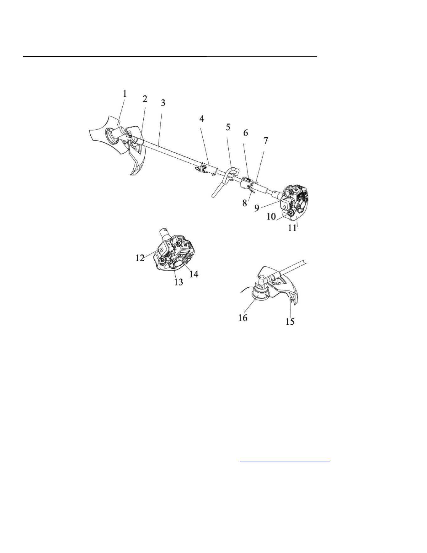
KNOWING YOUR BRUSH CUTTER&STRING TRIMMER
Please use the illustration below to familiarize yourself with the location and function of the components
that control of your brush cutter.
Unpacking
Unpack the blower and all its parts, and compare against the list below. Do not discard the carton or any
damaged or missing.
Including:
Brush Cutter / Trimmer Head / Blade / Blade Shield / Handle / Shoulder Harness / S3
、
S4 Hex Key /
Spark Plug Wrench / Oiler / User Manual
1
Blade
9
Purge Bulb
2
Blade Shield
10
Fuel Tank Lid
3
Shaft
11
Fuel Tank
4
Connector Cover
12
Air Cleaner Cover
5
D-Handle
13
Choke
6
On/Off Switch
14
Starter Handle
7
Safety Lever
15
Cut-off Knife
8
Throttle Trigger
16
Trimmer head
10
ASSEMBLY INSTRUCTION
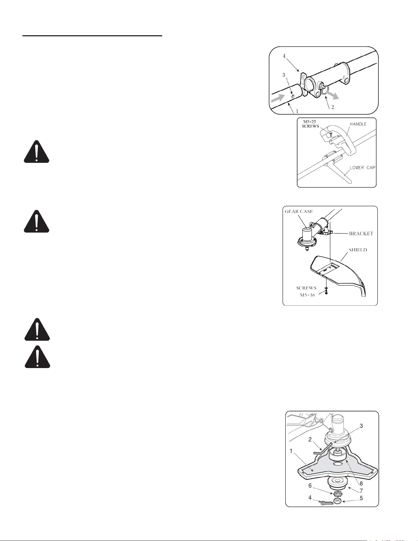
Handle Installation
1. Pull out the stop pin (2) and push the lower part of the rod (1) right
down until the stop pin (2) slots into the hole (3) in the rod. This is easier
to do if you rotate the bottom of the rod (4) slightly in both directions.
The pin (2) is in place when it is completely lodged in the hole. Lastly,
tighten the knob (4) securely.
2. Position handle in a comfortable operating position and tighten four M5×25
screws.
WARNING: Do not attempt to disassemble the two special screws.
The two clamps position has been adjusted at a suitable place,do not
attempt to remove or move them. Otherwise, it can result in serious personal
injury.
Installing Plastic Blade Shield
CAUTION: The blade shield must be properly installed. This
shield helps provide partial protection to the operator and others
from the risk of thrown objects and other debris.
1. Install the safety cover on the shaft with the safety cover bracket and the
screws provided.
2. Tighten the screws after setting the safety cover bracket at the appropriate
position.
Brush Cutter Installation
WARNING: When installing brush cutter, place the unit on a flat surface for stability. Wear
protective gloves when handling on the blade to avoid injury as the blade is sharp.
WARNING: Do not attempt to use any blades, washers, nuts, or fastening hardware other than
shown in the following illustrations. These parts must be provided by the manufacturer and
installed as shown below. Failure to use proper parts can cause the blade to fly off and seriously hurt.
1. Insert the hex key (2) into the specific hole in the angle transmission (3) and rotate the blade (1) by
hand until the hex key enters the inner hole, blocking rotation as shown in the picture.
2. Remove the split pin (4) and unscrew the nut (5) in a clockwise direction.
3. Pull out the washer (6) and the outer ring-nut (7) and remove blade.
Ensure that the grooves in the inner ring-nut (8) mach up perfectly with the
angle transmission (3).
4. Fit the blade (1) and outer ring-nut (7).
5. Refit the washer (6) and the nut (5), fully tightening it in an anticlockwise
direction.
6. Reposition the split pin (4) and refold the two ends. Then remove the hex
key (2).
11
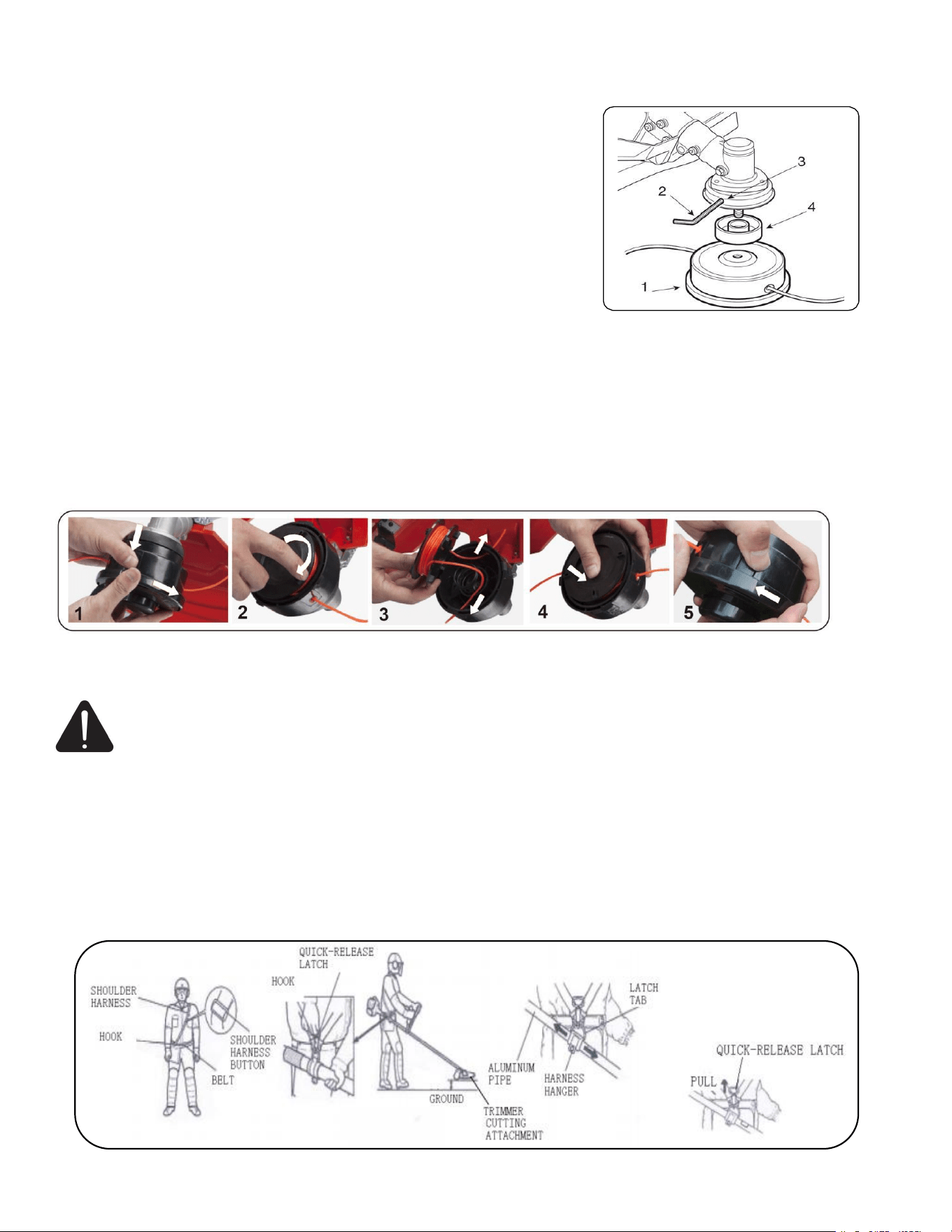
String Trimmer Installation
Headline Installation
1. Insert the hex key (2) into the specific hole in the angle transmission
(3) and rotate the cutting line head (1) by hand until the hex key enters
the inner hole, blocking rotation as shown in the picture.
2. Ensure that the grooves in the inner ring-nut (4) mach up perfectly
with the angle transmission(3).
3. Fit the cutting line head (1) screwing it up in an anticlockwise
direction.
4. Remove the hex key (2), the headline installation is finished.
Headline Replacement
1. Press the arrow site beside the trimmer line head, rotate clockwise to remove the head as shown in the
below picture.
2. Take the wire reel off by rotating it clockwise.
3. Take a new wire reel. thread the wire into the holes on both sides of the reel in the direction of the arrow
on the wire line.
4. Press the new wire reel into the head and cock the wire on both sides of the wire reel.
5. Put the cap back and tighten the cover of the trimmer head by rotating it counterclockwise. The trimmer
line is replaced successfully.
Using The Shoulder Harness
WARNING: Proper shoulder strap and handlebar adjustments must be made with the engine
completely stopped before using unit.
1. Assemble and adjust the shoulder harness and belt as shown in the below picture.
2. Adjust the shoulder-harness button,and move the hook to your waist, then adjust the belt (If there
is a belt).
3. Hang the latch tab on the harness hook. If the brush cutter doesn't balance, then adjust the harness
hanger, and the handlebar, until it balances.
4. To quickly detach the brush cutter from the harness, pull the quick-release latch tab upward.
5. Insert the latch tongue in the slot of the quick-release latch to reattach the brush cutter to the harness.

12
MIXTURE RATIO IS 50:1
WARNING: Before using, please check the shoulder harness and confirm it is OK. Encounter
danger, please stop the brush cutter immediately,and pull the quick-release latch tab, the brush
cutter will be depart from your body.
Fuel&Oil Mixture
The fuel and oil mixture ratio is 50:1.
Never fill the fuel tank to the very top (under 3/4 of the tank).
Never add fuel to the tank in a closed non-ventilated area.
Do not add fuel to this unit close to an open fire or sparks.
Be sure to wipe off spilled fuel before attempting to start engine.
Do not attempt to refuel a hot engine.
Fuel used for this model is a mixture of unleaded gasoline and approved
engine lubricant. When mixing gasoline with two-cycle engine oil, use
only gasoline which contains NO ETHANOL or METHANOL (Types of
Alcohol). Use fresh (within 30 days from purchase) 87 octane or higher unleaded gasoline known to be of
good quality. This will help to avoid possible damage to engine fuel lines and other engine parts.
WARNING: Fuel mixture at the rate other than 50:1 may cause damage to the engine,Ensure
mixture ratio is correct. Do not mix gasoline and oil directly in the engine fuel tank.
WARNING: The engine exhaust from this product contains chemicals known to cause cancer,
birth defects, or other reproductive harm.
FUEL
The engine uses two-stroke fuel, a mixture of gasoline and 2-stroke lubricant 50:1.
GASOLINE
Use fresh (within 30 days from purchase) 87 octane or higher unleaded gasoline known to be of good
quality.
STORING FUEL
Store fuel only in a clean,safe, approved container. Check and follow local ordinances on type and location
of storage container.
FUEL AND OIL MIXTURE
Inspect fuel tank making sure that it is clean and fill with fresh fuel. Use a mixture of 50:1.
IMPORTANT !
2-stroke fuel may separate. Shake fuel container thoroughly before each use. Stored fuel ages. Do not mix
more fuel than you expect to use within a month.
Fig.6
13
OPERATING INSTRUCTION
WARNING: Be sure to read the fuel information in the safety rules before you begin. If you do
not understand the safety rules, do not attempt to fuel your unit. Call customer support.
Check Points Before Operation
Check for loose bolts, nuts and fittings.
Check the air cleaner for dirt. Clean the air filter of all dirt, etc. before operation.
Check to be sure that protector is securely in place.
Check to be sure that fuel is not leaking.
Check to be sure that blade is not cracked.
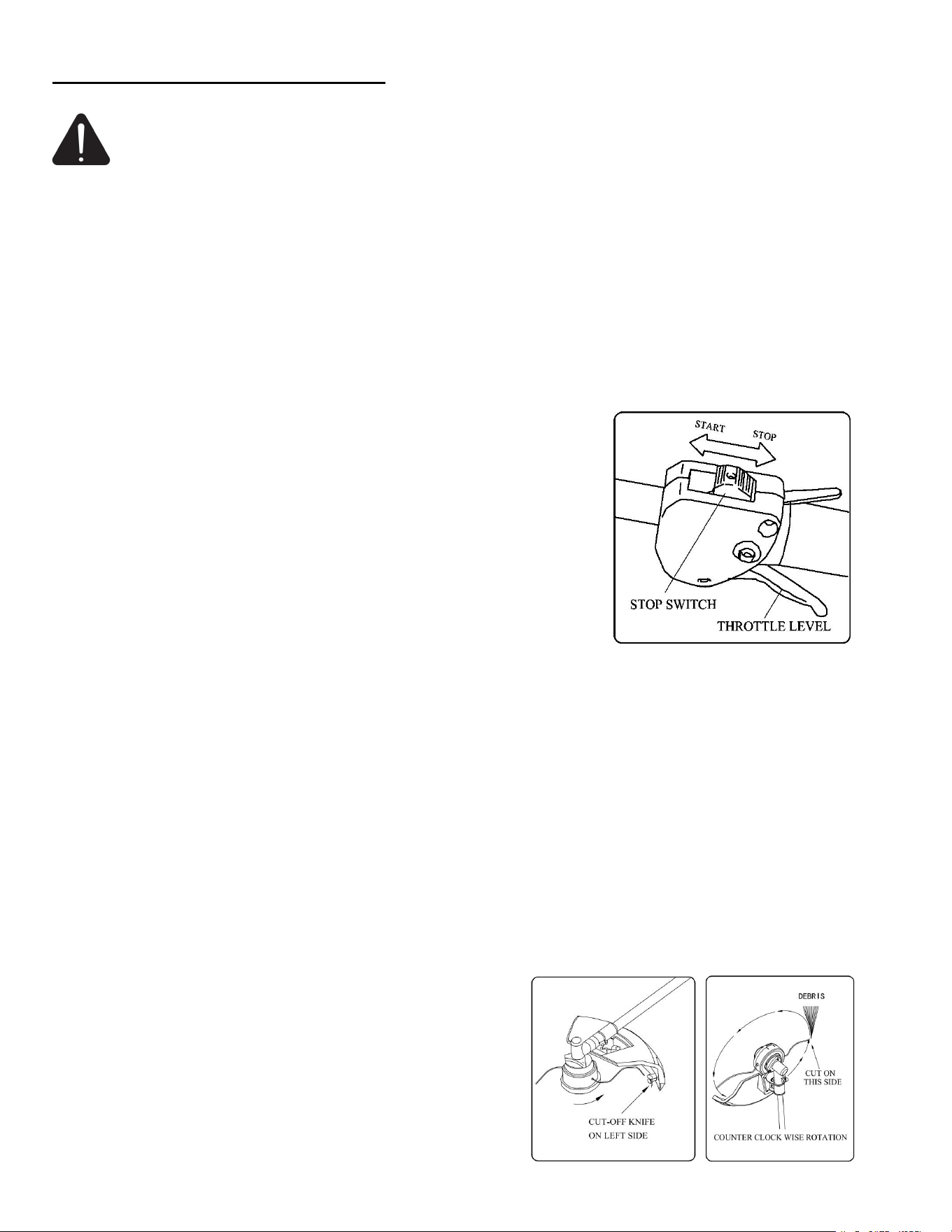
Starting Cold Engine
1. Move the stop switch to "START" position.
2. Give a gentle push on the primer pump repeatedly (7-10times) until
fuel comes into the primer pump.
3. Pull lever up to close choke.
4. Pull starter handle until engine flash fires.
5. Push choke lever inwards( excessive cranking with choke lever will
cause flooding engine making it difficult to start.)
6. Pull starter handle until engine starts.
7. Allow engine to warm up for a few minutes before using.
Starting Warm Engine
1. Push the choke lever to the "RUN".
2. If fuel tank was not run dry, pull starter one to three times and engine should start.
3. If the fuel tank was empty, after refilling repeat steps 1-2-7 of starting cold engine instructions.
NOTE: If the starter rope is pulled repeatedly with the choke on, it may flood the engine and make starting
difficult. If you have flooded the engine, remove the spark plug and gently pull the handle on the starter
rope to eliminate any excess fuel, then dry the spark plug electrodes and replace it on the engine.
Stopping The Engine
1. Release the throttle trigger and allow the engine to run idle for a few seconds.
2. Move switch to “STOP” position.
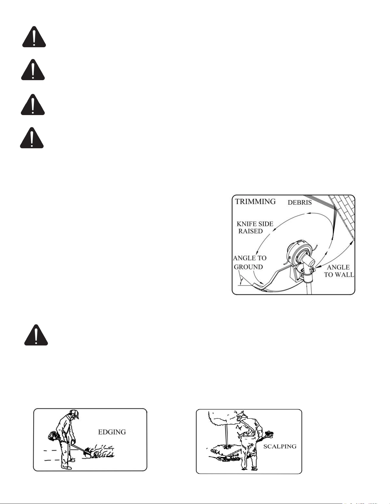
Cutting With a Nylon Head
Line head rotates in a counter CLOCKWISE direction.The
CUT-OFF KNIFE will be on the right side of the debris
shield. For nearly all cutting, it is good to tilt the line head so
that contact is made on the part of the line circle where the
line is moving away from you and the debris shield. This
results in the debris being thrown away from you.
14
WARNING: The proper debris shield must be in place on the unit when nylon cutting line is used.
The cutting line can flap around if too much line is exposed. Always use the plastic debris shield
with cut-off knife when using nylon cutting heads.
WARNING: Tilting the head to the wrong side will shoot the debris TOWARDS you.If the line
head is held flat to the ground so that cutting occurs on the whole line circle, debris will be
THROWN at you, drag will slow the engine down, and you will use up a lot of line.
WARNING: Use only quality nylon monofilament line of the diameter 2.5mm. Never use wire or
wire-reinforced line in place of nylon trimmer line. Load your nylon line cutting head only with
nylon trimmer line of the proper diameter.
WARNING:Use extreme caution when operating over bare spots and gravel, because the line can
throw small rock particles at high speeds. Debris shields on the unit cannot stop objects which
bounce or ricochet off hard surfaces.
Trimming
This is feeding the trimmer carefully into the material you wish to
cut .Tilt the head slowly to direct debris away from you. If cutting
up to a barrier such as fence, wall or tree,approach from an angle
where any debris ricocheting off the barrier will fly away from
you. Move the line head slowly until the grass is cut right up the
barrier, but do not jam(overfeed )the line into the barrier. If
trimming up to a wire mesh or chain linked fence be careful to
feed only up to wire. If you go to far the line will snap off around
the wire. Trimming can be done to cut through weed stems one at
a time. Place the trimmer line head near the bottom of the weed-
never high up which could cause the weed to chatter and catch
the line. Rather than cut the weed right through, just use the very
end of the line to wear through the stem slowly.
Scalping And Edging
WARNING: Do not use a steel blade for edging or scalping.
Both of these are done with the line head tilted at a steep angle. Scalping is removing top growth. Edging is
trimming the grass back where it has spread over a sidewalk or drive way. During both edging and scalping,
hold the unit a steep angle and in a position where the debris, and any dislodging dirt and stones, will not
come back towards you even if it ricochets off the hard surface.
Although the picture shows how to edge and scalp every operator must find for himself the angles which
suits his body size and cutting situation.

15
WARNING:Do not trim in any area where there are strands
of fencing wire. Wear protective safety protecting, Do not
cut where you cannot see what the cutting device is cutting.
Cutting With a Blade
WARNING: Do not use a brush cutter for cutting trees.
There are many different types of blades, however the two most commonly used are the following. Brush
blade is used for cutting brush and weeds up to 3/4” in diameter. Only 255mm 3-blade can be used in this
type of brush cutter.
WARNING: Do not cut with dull, cracked or damaged metal blade.
Before cutting growth, inspect for obstructions such as boulders,
metal stakes or strands of wire from broken fences. If an obstruction cannot
be removed, mark its location so broken fences. If an obstruction cannot be
removed, mark its location so that you can avoid it with the blade. Rocks and
metal will dull or damage a blade. Wires can catch on the blade head and flap
around or be thrown into the air.
Blade thrust is the reaction which may occur when the spinning blade
contacts anything it cannot cut.This contact may cause the blade to stop for
an instant ?and suddenly "thrust" the unit away from the object that was hit.
This reaction can be violent enough to cause the operator to lose control of
the unit. Blade thrust may occur without warning if the blade snags ,stalls
or binds.This is more likely to occur in areas where it is difficult to see the
material being cut from cutting ease and safely, approach the weeds being
cut from the right to the left,in the event that an unexpected object or
woody stock is encountered,this could minimize the blade thrust reaction .
Scything Weeds
This is cutting by swinging the blade in a level area. It can quickly clear areas of field grass and weeds.
Scything should not be used to cut large, tough weeds or woody growths.
NOTE: Do not use a brush blade to cut trees which exceed a diameter of 1/2 to 3/4 inch.
Scything can be done in both directions, or just in one way which results
in the debris being thrown away from you. That is using the side of the
blade that it is rotating away from you. Tilt down the blade slightly on
this same side .You will be hit by some debris if you scythe in both
directions.
Do not force the blade to cut.
Do not change the angle of cut after into the wood.
Avoid using any pressure or leverage which could cause the blade to
bind or crack.
16
MAINTENANCE
WARNING: Use only original manufacturer's replacement parts, accessories and attachments.
Failure to do so can cause possible injury, poor performance and may void your warranty.
The cutting attachment must not rotate in idle mode.If this requirement is not satisfied,the cluth has to be
adjusted or the machine needs an urgent maintenance by a qualified technician.
You may make adjustments and repairs described here.For other repairs,have the trimmer serviced by an
authorized service agent.
Consequences of improper maintenance may include excess carbon deposits resulting in loss of
performance and discharge of black oily residue dripping from the muffler.
Make sure all guards,straps,deflectors and handles are properly and securely attached to avoid the risk of
personal injury.
Exhaust Port And Silencer
Depending on the type of fuel used,the type and amount of oil used,and/or your operating conditions,the
exhaust port and silencer may become blocked with carbon deposits.If you notice a power loss with your
petrol powered tool. A qualified service technician will need to remove these deposits to restore
performance.
Adjusting Carburetor
Do not adjust carburetor unless necessary. If you have trouble with the carburetor, see your dealer. Improper
adjustment may cause engine damage and void warranty.
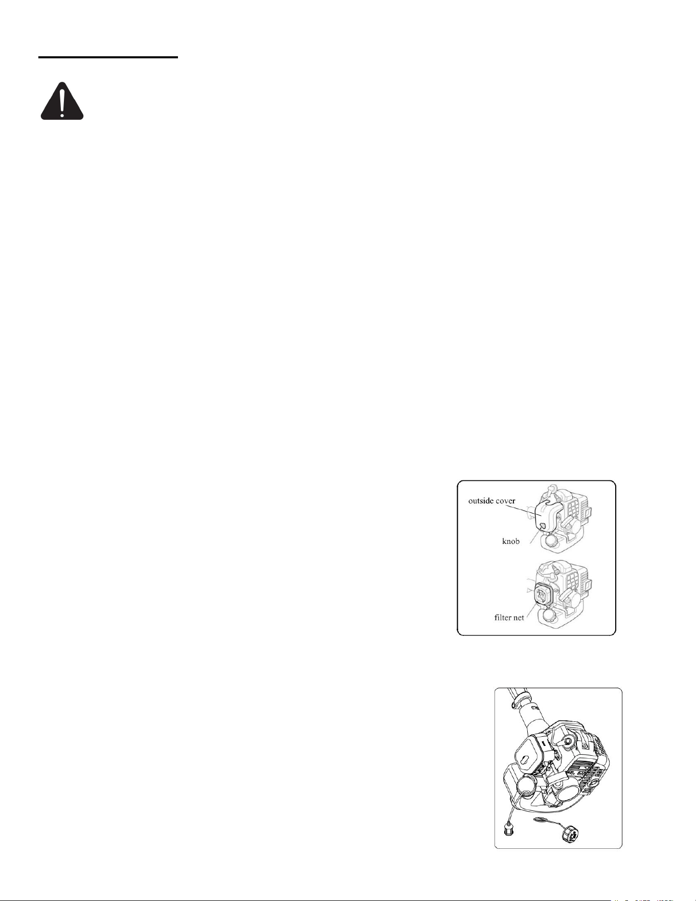
Air Filter
Accumulated dust in the air filter will reduce engine efficiency.
Increase fuel consumption and allow abrasive particles to pass into the
engine.
1. Remove the air filter as often as necessary to maintain in a clean
condition.
2. Light surface dust can readily be removed by tapping the filter. Heavy
deposits should be washed out in suitable solvent.
3. Remove filter cover by loosening air filter cover knob.
Fuel Filter
Fuel tank is fitted with a filter.Filter is situated at the free end of fuel pipe and can be picked out through
fuel port with a piece of hooked wire or the like.
Check the fuel filter periodically. Do not allow dust to enter into fuel tank.
Clogged filter will cause difficulty in starting engine or abnormalities in
engine performance.
When filter is dirty, replace the filter.
When the inside of the fuel tank is dirty, it can be cleaned by rinsing the
tank out with gasoline.
17
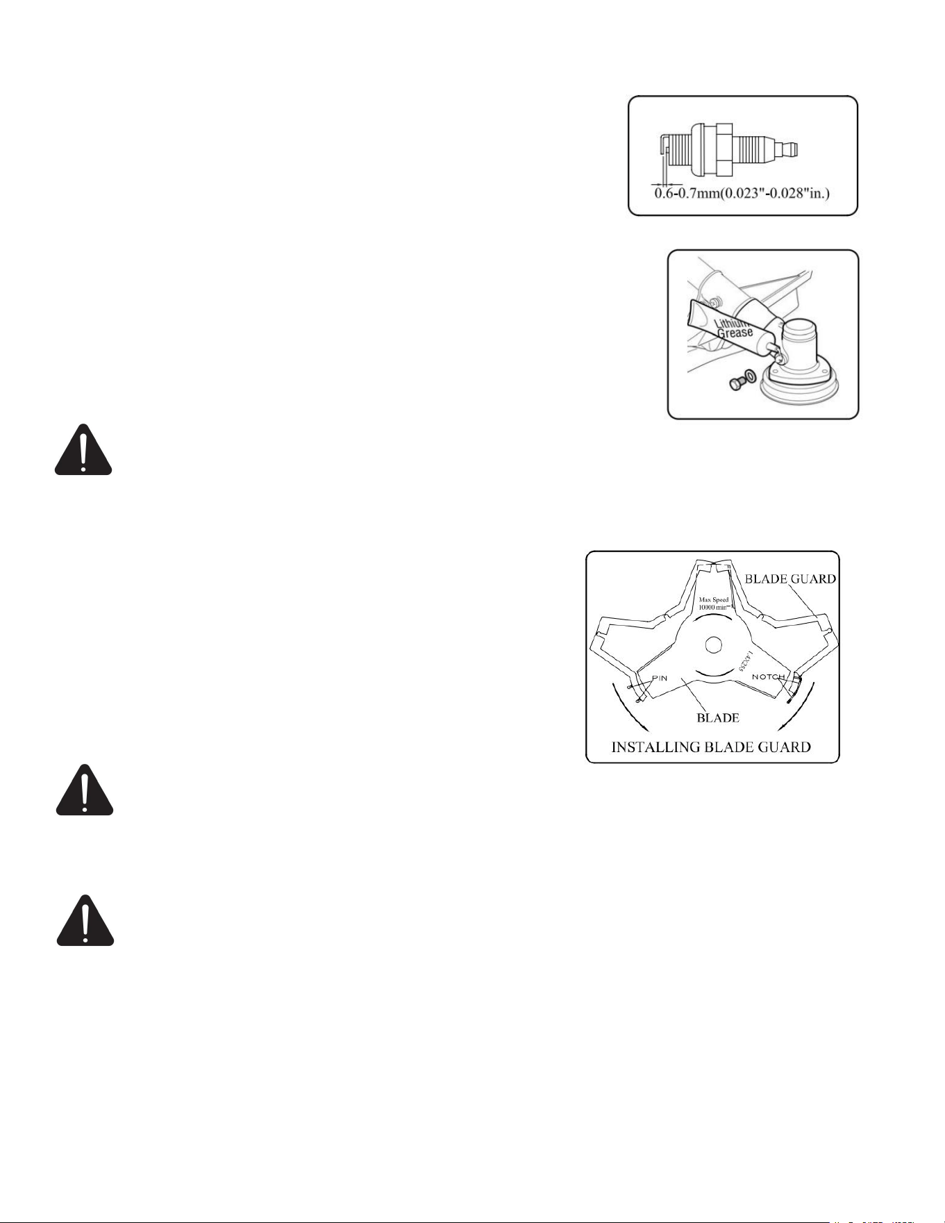
Spark Plug
Do not attempt to remove the plug from a hot engine in order to avoid
possible damage to the threads.
Clean or replace the plug if fouled with heavy oily deposits.
Replace the plug if the center electrode is worn rounded at the end.
Spark gap is 0.6-0.7mm (.023”.028").
Fastening torque =14-15Nm(125-135in.lb).
Bevel Gear
After working (40-50) hours, fill with the right quantity of grease.
Remove the screw and put in the lithium-based grease. turning the shaft
manually until grease emerges, then refit the wash the screw.
Transport
WARNING: Please empty the fuel tank before transporting, to avoiding the engine leaked. For
avoiding the cutting attachment damaged the brush cutter and people, please removed the
cutting attachment ,and resile the brush cutter as factory state , then casting all parts into the package.
Before transporting, all parts should be packed and validated safe.
1. The engine should be turned off when the unit is moved between
work areas.
2. After the engine has stopped ,the muffler is still hot. Never touch
hot parts such as the muffler.
3. Confirm that the fuel has not leaked from the tank.
4. Allow the engine to cool, empty the fuel tank and secure the unit
from moving before transporting in a vehicle, if the blade is fitted,
always use the blade guard.
5. Open the blade guard and install on the blade, then put the pin
into the guard notch.
WARNING: Always place the blade guard on the blade when the unit is not in use. Remove the
blade guard before using the unit. If not removed, the blade guard could become a thrown object
as the blade begins to turn.
Storage
WARNING: Do not store in a closed area where fuel vapors can reach an open flame from hot
water heaters, heaters, furnaces, etc. Store in a locked, well ventilated area only.
Inspect, clean and repair unit if necessary.
Remove all fuel from tank.
Start engine-This will consume all fuel in fuel line and carburetor.
Remove spark plug and pour one tea spoon of clean motor oil into spark plug hole of cylinder-replace
spark plug.
Store in clean, dry, dust free area.

18
TROUBLESHOOTING
Failure To Start
Low Output
Symptom
Probable cause
Remedy
Cylinder
compres
s
pressure
normal.
Spark
plug
spark
normal.
Fuel system
Abnormality.
1. These is no fuel in tank.
2. Fuel filter obstructed.
1. Add fuel in tank.
2. Clean fuel filter.
Fuel
system
normal.
Fuel
1. Fuel is too dirty.
2. There is water in fuel.
3. There is too much fuel in
cylinder.
4. Mixture ratio is improper.
1. Replace fuel.
2. Replace fuel.
3. Take down spark plug
and dry it.
4. Mixture proration.
Fuel
system
normal.
High
voltage
wire spark
normal.
Spark
plug
1. Spark plug fouled with oily
deposits.
2. Spark plug insulation
damage.
3. Spark gap is too large or
small.
1. Clean the oily deposits.
2. Replace spark plug.
3. Adjust spark gap 0.6-
0.7mm.
High voltage wire
spark abnormality.
1. High voltage wire breach or
break off.
2. Coil looseness.
1. Replace or tighten.
2. Tighten.
Fuel
system
normal.
Ignition
system
normal.
Compression pressure
is inadequate.
1. Piston ring attrite.
2. Piston ring is broken.
3. Piston ring cementation .
4. Spark plug looseness .
5. Conjoint surface of the
cylinder and crank case leak.
1. Replace a new.
2. Replace.
3. Eliminate.
4. Tighten.
5. Eliminate.
Compression normal.
1. High voltage wire and spark
plug contact poor
2. Stop switch failure or short
circuit
1. Tighten the spark plug
cap
2. Repair or replace
Symptom
Probable cause
Remedy
1. Flame out when speedup.
2. The smoke is thin, carburetor
spout backward.
1. Fuel filter obstruct, fell short of
fuel.
2. Muffler fouled with oily
deposits.
1. Clean fuel filter、clean fuel
road、 adjust carburetor.
2. Clean the oily deposits.
Compress press is inadequate.
Piston、piston ring、cylinder
attrite
Replace piston
、
piston ring.
Engine leak.
Conjoint surface of the cylinder
and crank case leak.
Repair.
The end of two crank shaft leak.
The seal is bad.
Replace seal.
1. Engine overheats.
2. Burning room fouled with oily
deposits.
1. Avoid use it for long time、
high speed and heavy load.
2. Clean the oily deposits.

19
Engine Running Unstable
Symptom
Probable cause
Remedy
There are knock sound in
engine.
1. Piston、piston ring、cylinder
attrite.
2. Piston pin、piston attrite.
3. Bearing of crank shaft attrite.
1. Replace piston、piston ring.
2. Replace piston pin、piston.
3. Replace bearing.
There are metal knock
sound.
1. Engine overheats.
2. Burning room fouled with oily
deposits.
3. Gasoline branded is unfit.
1. Avoid use it for long time
、
high
speed and heavy load.
2. Clean the oily deposits.
3. Replace with required branded.
octane
Engine ignition break off.
1. There is water in fuel.
2. Spark gap is wrong.
3. Coil gap is wrong.
1. Instead fuel
2. Adjust spark gap 0.6-0.7mm
3. Adjust coil gap 0.3-0.4mm
The Engine Suddenly Stopped
Probable cause
Remedy
1. Fuel has been used up.
2. Spark plug fouled with oily deposits and short circuit high
voltage wire fall off.
1. Add fuel.
2. Clean the oily deposits connect.
20
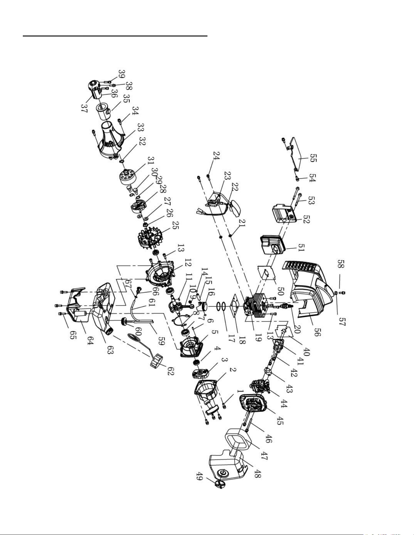
EXPLODED VIEW AND PARTS LIST
Engine exploded view

21
Engine parts list
Item
Stock #
Description
Qty
Item
Stock #
Description
Qty
1
GB70.1+GB93+GB97
Screw M5×16
4
35
CG305F-HS.1-3
Rubber
1
2
P23.10A
Starter
1
36
CG305F-HS.1-1
Holder A
1
3
P23.9A
Guide Cover assy
1
37
CG305F-HS.1-2
Holder B
1
4
1E36F.2
Oil seal
2
38
GB70.1+GB93+GB97
Screw M5
×
16
1
5
P23.11-2
Crank case R
1
39
GB70.1+GB93+GB97
Screw M5
×
25
2
6
GB/T119.1
Pin 4
×
h8
×
8
2
40
P23-7
Gasket insulator
1
7
GB/T276
Bearing 6001/P53
2
41
P23.3
Insulator
1
8
P23.11-3
Gasket crank case
1
42
GB70.1+GB93+GB97
Screw M5×25
2
9
KBK081211.5
Bearing
1
43
1E36F-2A-1
Gasket carburetor
1
10
P23.6A.1
Crank shaft assy
1
44
1E34F-2E.1A
Carburetor
1
11
1E40FP-3Z.3-1
Key
1
45
1E34F.1.1
Cleaner base assy
1
12
P23.11-1
Crank case F
1
46
GB70.1+GB97.1
Screw M5
×
60
2
13
GB/T70.1
Screw M5
×
16
7
47
1E34F.1-1
Air filter element
1
14
1E34F.6-2
Ring snap
2
48
HP23.1-1
Cover cleaner
1
15
1E34F.6-3
Piston pin
1
49
1E34FG.1.1
Knob cover
1
16
P26.1A-1
Piston
1
50
1E34F-3
Gasket muffler
1
17
1E34F.6-5
Ring piston
2
51
1E34F-2E.2
Muffler
1
18
P23-2
Gasket cylinder
1
52
HP23-5A
Cover
1
19
P26-1
Cylinder
1
53
HP23-8
Screw M5×55-10.9
2
20
CMR6A
Spark plug
1
54
GB70.1+GB93+GB97
Screw M5×14
2
21
PO40-5
Spacer Ig coil
2
55
HP23-2
Clapboard
1
22
P23.5.2
Wire lead assy
1
56
HP23.3
Top cover
1
23
HP23.2.1
IG coil
1
57
1E33F-4
Spacer Ig coil
1
24
GB70.1+GB93+GB97
Screw M4
×
20
2
58
GB70.1+GB93+GB97
Screw M5
×
18
1
25
P23.5.1.1
Rotor magnet
1
59
EB-415.4.2-4
Fuel pipe 2.5
×
1.25
×
100
1
26
GB/T6177
Nut M8
1
60
EB415.4.2-2
Plug
1
27
1E34F-11
Wave washer
2
61
CG420.1.3.2-2
Fuel pipe 3
×
1
×
165
1
28
1E34F.10D
Clutch assy
1
62
IE32FL.6.2B
Tank cap assy
1
29
1E34F-13
Washer
2
63
HP23.6.1
Fuel tank
1
30
1E34F-12
Clutch bolt
2
64
HP23.4
Stand
1
31
CG260A.1A.1
Clutch drum assy
1
65
GB70.1+GB93+GB97
Screw M5×20
3
32
GB/T894.1
Circlips for shaft-
type A15
1
66
P40.12.2-3A
Filter
1
33
HP23.5.1
Fan cover
1
67
P23.12-1
Snap rings
1
34
GB70.1+GB93+GB97
Screw M5
×
18
3

22
Brush cutter &String trimmer exploded view and parts list
Item
Stock #
Description
Qty
A
PS4532-A
Gear Case Assy
1
1
AM4532-A-01
Stop Ring 26
1
2
AM4532-A-02
Stop Ring 10
1
3
AM4532-A-03
Bearing 6000-2RS/P6
1
4
AM4532-A-04
Bearing 6000/P6
2
5
AM4532-A-05
Pinion
1
6
AM4532-A-06
Screw M5
×
20
1
7
AM4532-A-07
Screw M5
×
12
4
8
AM4532-A-08
Bolt M5×12
1
9
AM4532-A-09
Gear Case
1
10
AM4532-A-10
Safety Guard
1
11
AM4532-A-11
Gear
1
12
AM4532-A-12
Gear Shaft
1
13
AM4532-A-13
Bearing 6002-2RS/P6
1
14
AM4532-A-14
Stop Ring 32
1
15
AM4532-A-15
Holder A
1
16
AM4532-A-16
Holder B
1
17
AM4532-A-17
Washer 10
1
18
AM4532-A-18
Left Nut
1
19
AM4532-A-19
Pin 2×16
1
Item
Stock #
Description
Qty
B
AM4532-B
Handle
1
1
AM4532-B-01
Screw M5
×
35
4
2
AM4532-B-02
Handle
1
3
AM4532-B-03
Rubber Cover
1
4
AM4532-B-04
Handle Cover
1
Item
Stock #
Description
Qty
C
AM4532-C
Clamp
2
1
AM4532-C-01
Clamp
1
2
AM4532-C-02
Screw M5×35
1
3
AM4532-C-03
Nut M5
1

23
Item
Stock #
Description
Qty
D
AM4532-D
Fore-Pipe Comp.
1
1
AM4532-D-01
Hose Sleeve
1
2
AM4532-D-02
Rubber Cover
3
3
AM4532-D-03
Oil-bearing
3
4
AM4532-D-04
Drive Shaft
1
5
AM4532-D-05
Pipe
1
Item
Stock #
Description
Qty
E
AM4532-E
Rear-Pipe Comp.
1
1
AM4532-E-01
Ribber Pipe (5mm)
1
2
AM4532-E-02
Rubber Cover
3
3
AM4532-E-03
Oil-bearing
3
4
AM4532-E-04
Pipe
1
5
AM4532-E-05
Drive Shaft
1
6
AM4532-E-06
Adapter Comp.
1
Item
Stock #
Description
Qty
Item
Stock #
Description
Qty
F
AM4532-F
Joining Ass’y
1
8
AM4532-F-08
Washer 6
1
1
AM4532-F-01
Bolt M6×55
1
9
AM4532-F-09
Bin
1
2
AM4532-F-02
Nut M5
1
10
AM4532-F-10
Spring
1
3
AM4532-F-03
Joining
1
11
AM4532-F-11
Cover
1
4
AM4532-F-04
Bolt M5×12
1
12
AM4532-F-12
Loop
1
5
AM4532-F-05
Nut M6
1
13
AM4532-F-13
Bin comp.
1
6
AM4532-F-06
Screw M6
1
14
AM4532-F-14
Screw M5×25
1
7
AM4532-F-07
Handle
1
15
AM4532-F-15
Washer
1

24
Item
Stock #
Description
Qty
G
AM4532-G
Level Assy
1
1
AM4532-G-01
Clamp
1
2
AM4532-G-02
Screw M5
×
16
1
3
AM4532-G-03
Tine
1
4
AM4532-G-04
Spring
1
5
AM4532-G-05
Spring
1
6
AM4532-G-06
Spring
1
7
AM4532-G-07
Safety Lever
1
8
AM4532-G-08
Throttle Lever
1
9
AM4532-G-09
Cable Comp.
1
10
AM4532-G-10
Screw M5
×
25
2
11
AM4532-G-11
Nut M5
3
12
AM4532-G-12
Box, left
1
13
AM4532-G-13
Stop Switch
1
14
AM4532-G-14
Tube (12.5
×
170)
1
15
AM4532-G-15
Screw M5×30
1
16
AM4532-G-16
Clamp
1
17
AM4532-G-17
Rubber Cover
1
18
AM4532-G-18
Box, Right
1
Item
Stock #
Description
Qty
H
AM4532-H
Holder Assy
1
1
AM4532-H-01
Harness Clamp
1
2
AM4532-H-02
Clamp
1
3
AM4532-H-03
Screw M5×20
1
4
AM4532-H-04
Nut M5
1

25
Item
Stock #
Description
Qty
I
AM4532-I
Guard Assy
1
1
AM4532-I-01
Bracket
1
2
AM4532-I-02
Screw M5×30
2
3
AM4532-I-03
Screw M5×12
1
4
AM4532-I-04
Screw ST4.2×16
1
5
AM4532-I-05
Safety Guard
1
6
AM4532-I-06
Screw M5×16
4
7
AM4532-I-07
Guard Assy
1
8
AM4532-I-08
Guard
1
9
AM4532-I-09
Screw ST4.2×16
2
10
AM4532-I-10
Blade
1
Item
Stock #
Description
Qty
J
AM4532-J
Nylon Cutter Head
1
1
AM4532-J-01
Case
1
2
AM4532-J-02
Spring
1
3
AM4532-J-03
Cord φ2.5×2100
2
4
AM4532-J-04
Cord Holder
1
5
AM4532-J-05
Cover
1
6
AM4532-J-06
Cover
1
Item
Stock #
Description
Qty
K
AM4532-K
Harness Assy
1
L
AM4532-L
Blade
1
M
AM4532-M
Blade Guard
1

26
ONE (1) YEAR LIMITED WARRANTY
Amerisun is committed to building equipment that will provide years of dependable service. Our warranties are
consistent with our commitment and dedication to quality.
ONE (1) YEAR LIMITED WARRANTY OF AMERISUN PRODUCTS FOR HOME USE.
Amerisun (
“
Seller") warrants to the original purchaser only, that all Amerisun consumer power tools will be free
from defects in material or workmanship for a period of one (1) years from date of purchase. Sixty (60 days for all
Amerisun Products, if the tool is used for professional or commercial use.
SELLER’S SOLE OBLIGATION AND YOUR EXCLUSIVE REMEDY under this One (1) Year Limited
Warranty and, to the extent permitted by law, any warranty or condition implied by law, shall be the repair or
replacement of parts, without charge, which are defective in material or workmanship and which have not been
misused, carelessly handled, or misrepaired by persons other than Seller or Authorized Service Center. To make a
claim under this Limited Warranty, you must return the entire power tool product; transportation prepaid, to
Amerisun include a legible copy of the original receipt, which lists the date of purchase (month and year) and the
name of the company purchased from.
THIS LIMITED WARRANTY DOES NOT APPLY TO ANY ACCESSORY ITEMS INCLUDED WITH THE
TOOL SUCH AS STRING TRIMMER HEAD OTHER RELATED ITEMS OR TO ANY REPLACEMENT
PARTS LISTED UNDER MAINTENANCE.
ANY IMPLIED WARRANTIES SHALL BE LIMITED IN DURATION TO ONE (1) YEAR FROM DATE OF
PURCHASE. SOME STATES IN THE U.S. AND SOME CANADIAN PROVINCES DO NOT ALLOW
LIMITATIONS ON HOW LONG AN IMPLIED WARRANTY LASTS, SO THE ABOVE LIMITATION MAY
NOT APPLY TO YOU.
IN NO EVENT SHALL SELLER BE LIABLE FOR ANY INCIDENTAL OR CONSEQUENTIAL DAMAGES
(INCLUDING BUT NOT LIMITED TO LIABILITY FOR LOSS OF PROFITS) ARISING FROM THE SALE
OR USE OF THIS PRODUCT. SOME STATES IN THE U.S. AND SOME CANADIAN PROVINCES DO
NOT ALLOW THE EXCLUSION OR LIMITATION OF INCIDENTAL OR CONSEQUENTIAL DAMAGES,
SO THE ABOVE LIMITATION OR EXCLUSION MAY NOT APPLY TO YOU.
THIS LIMITED WARRANTY GIVES YOU SPECIFIC LEGAL RIGHTS, AND YOU MAY ALSO HAVE
OTHER RIGHTS WHICH VARY FROM STATE TO STATE IN THE U.S., PROVINCE TO PROVINCE IN
CANADA AND FROM COUNTRY TO COUNTRY.
For questions / comments, technical assistance or repair parts –
Please call toll free at: 1-872-314-0005 (M-F 9am
–
5pm EST)
Email: support@amerisuninc.com
SAVE YOUR RECEIPTS. THIS WARRANTY IS VOID WITHOUT THEM.
