
USER MANUALPG 1
User Manual
Description: 54cm Freestanding Cooker
Front Control Models:
MODEL NO. EFS54FC-DCW / EFS54FC-DDS
Rear Control Models:
MODEL NO. EFS54RC-DRW / EFS54RC-DCW / EFS54RC-DCB
euromaid.com.au


USER MANUALPG 3
Conditions of use................................................................................................. 4
Safety precautions.............................................................................................. 4
Other important safety information.................................................................. 4
Warnings for use (of grill, oven, and appliance hob)...................................... 5
Disposal of packaging ....................................................................................... 5
Installation, cleaning and servicing................................................................... 5
Product description............................................................................................. 6
First time use of the appliance........................................................................... 8
Using the oven..................................................................................................... 9
Using the grill........................................................................................................ 13
Using the hotplates of your cooker................................................................... 14
Using the hotplate gas burners......................................................................... 16
Fitting oven accessories and cleaning............................................................ 17
Solving problems................................................................................................ 21
Installing cooker – power connections........................................................... 22
Installing the gas cooker................................................................................... 23
Testing the operation of the gas cooker......................................................... 25
Installing your new cooker................................................................................ 26
Technical specifications................................................................................... 29
Warranty............................................................................................................ 31
CONTENTS
We recommend that you read the instructions in this manual carefully before use for the best performance
and to extend the life of your appliance, as it will provide you with all the instructions you require to ensure
its safe installation, use and maintenance. Always keep this manual close to hand since you may need to
refer to it in the future. Thank you.
Condition of use:
This appliance is intended to be used for domestic use, not commercial use.

USER MANUALPG 4
• This appliance is not intended for use by persons (including children) with reduced physical, sensory or
mental capabilities, or lack of experience and knowledge, unless they have been given supervision or
instruction concerning use of the appliance by a person responsible for their safety.
• Warning – ensure that no downward pressure is applied to the oven door when open. in particular, do
not allow a child to climb on to open oven door
• Warning - accessible parts can become hot during use, especially the oven door. To avoid burns, young
children must be kept away.
• Young children should be supervised to ensure they do not play with this appliance.
• During use this appliance becomes hot.
• Care should be taken to avoid touching hot external and internal surfaces when in use. Use oven
gloves.
• Install cooker, shelving and fittings in accordance with this manual.
• Ensure all specified vents, openings and airspaces are not blocked.
• The appliance is not intended to be operated by means of external timer or separated remote-control
system.
• CAUTION: The cooking process has to be supervised. A short term cooking process has to be supervised
continuously.
• To ensure your safety all electric appliances should only be installed or service by qualified staff.
• If the supply cord when fitted, is damaged, it must be replaced a service agent or similarly qualified
person in order to avoid a hazard.
• Do not spray aerosols in the vicinity of this appliance while it is in operation.
• Do not store flammable materials in the appliance or near this appliance.
• Do not modify this appliance.
• Appliance must be installed according to current laws and regulations by qualified tradesmen/Installers
The Manufacturers, Importers/Distributors and Retailers shall not be liable to any legal liability, personal injury
and property damage due to incorrect operation or incorrect Installation.
OTHER IMPORTANT SAFETY INFORMATION
This appliance must not be used as a space heater.
Do not obstruct the ventilation slots on front or back of appliance.
Do not remove any labels or use abrasive/ corrosive cleaners on.
According to the electrical safety regulations the appliance equipment must be properly earthed.
Do not use corrosive cleaners e.g. oven cleaners that contain caustic soda.
SAFETY PRECAUTIONS

USER MANUALPG 5
WARNINGS FOR USE
GRILL WARNINGS
• DO NOT leave grill on unattended.
• DO NOT cover the grill tray wire rack with foil.
• Trying to grill food more than 25mm thick under grill can be a fire hazard. Trim excess fat from fatty
meats, such as pork and lamb.
• Fat left on a grill tray is a fire hazard! Keep grill clean and turn off grill immediately after use and leave
drawer open for a few minutes to cool grill area
OVEN WARNINGS
• Do not push down or apply any weight on open oven door.
• Do not line oven with foil or place anything on the bottom of the oven while baking to avoid permanent
damage, as trapped heat will crack or craze the enamel floor of the oven cavity liner.
• Use of olive oil and other poly-unsaturated oils (vegetable oils) when roasting uncovered food causes
deposits inside the oven which are very difficult to remove.
GENERAL HOTPLATE AND BURNER WARNINGS
• Do not allow pots to boil dry, as damage to hotplate may result.
• Do not operate hotplates or burners without a pot, fry pan etc.
• Do not allow cookware to overhang hob onto adjacent bench tops, this will cause scorching to the
bench top surface.
• Stainless steel sealing ring around the hotplate will discolour due to heat.
• Danger of fire: Do not store items on the cooking surface.
WARNING: Unattended cooking on a hob with fat or oil can be dangerous and may result in a fire.
CERAMIC HOTPLATE WARNINGS
• DO NOT place heat resistant mats, wire mats or aluminum foil under pots or pans.
• DO NOT cook food directly on the ceramic glass surface.
• DO NOT use round bottom woks or similar utensils which could lead to overheating of hotplates and
possible damage to the cooking surface. Cookware used should have completely flat bases.
• Ensure cookware states it is suitable for use on ceramic glass. Some aluminium and copper based
• cookware can cause minor pitting of the ceramic glass surface.
• DO NOT use the ceramic cook top as extra bench space or as a cutting board.
• AVOID dropping heavy objects onto the ceramic glass surface as damage can occur
• Immediately clean glass when sugary liquids have spilt eg. stewed fruit, jam, melted sugar.
• If the hob surface is cracked, switch off the appliance to avoid the possibility of electric shock
DISPOSAL OF PACKAGING
• Please recycle the cardboard and also any polystyrene packaging where possible.
INSTALLATION, CLEANING AND SERVICING
• An authorised person must install this appliance.
• Before using the appliance, ensure that all packing materials are removed from the appliance.
• In order to avoid any potential hazard, the Installation Instructions must be followed.
• In order to avoid accidental tipping of the appliance (for example, by a child climbing onto the open
oven door), the anti tilt plate must be installed.
• The cooker must not be placed on a base or plinth.
• The appliance must not be installed behind a decorative door in order to avoid overheating.
• Where the appliance is installed next to cabinets, the cabinet material must be capable of withstanding 85°C.
• Only authorised personnel should carry out servicing.
• Always ensure the appliance is switched off before cleaning.
• Do not use caustic soda- based cleaners.
• Do not use steam cleaners, as this may cause moisture build up.
• Always clean the appliance immediately after any food spillage.
• Appliances requiring connection to 220-240V and must be earthed.
• Means for disconnection must be incorporated in the fixed wiring in accordance with the wiring rules.
• Gas models are NOT APPROVED for installation in marine craft, caravans or mobile homes
USER MANUALPG 6
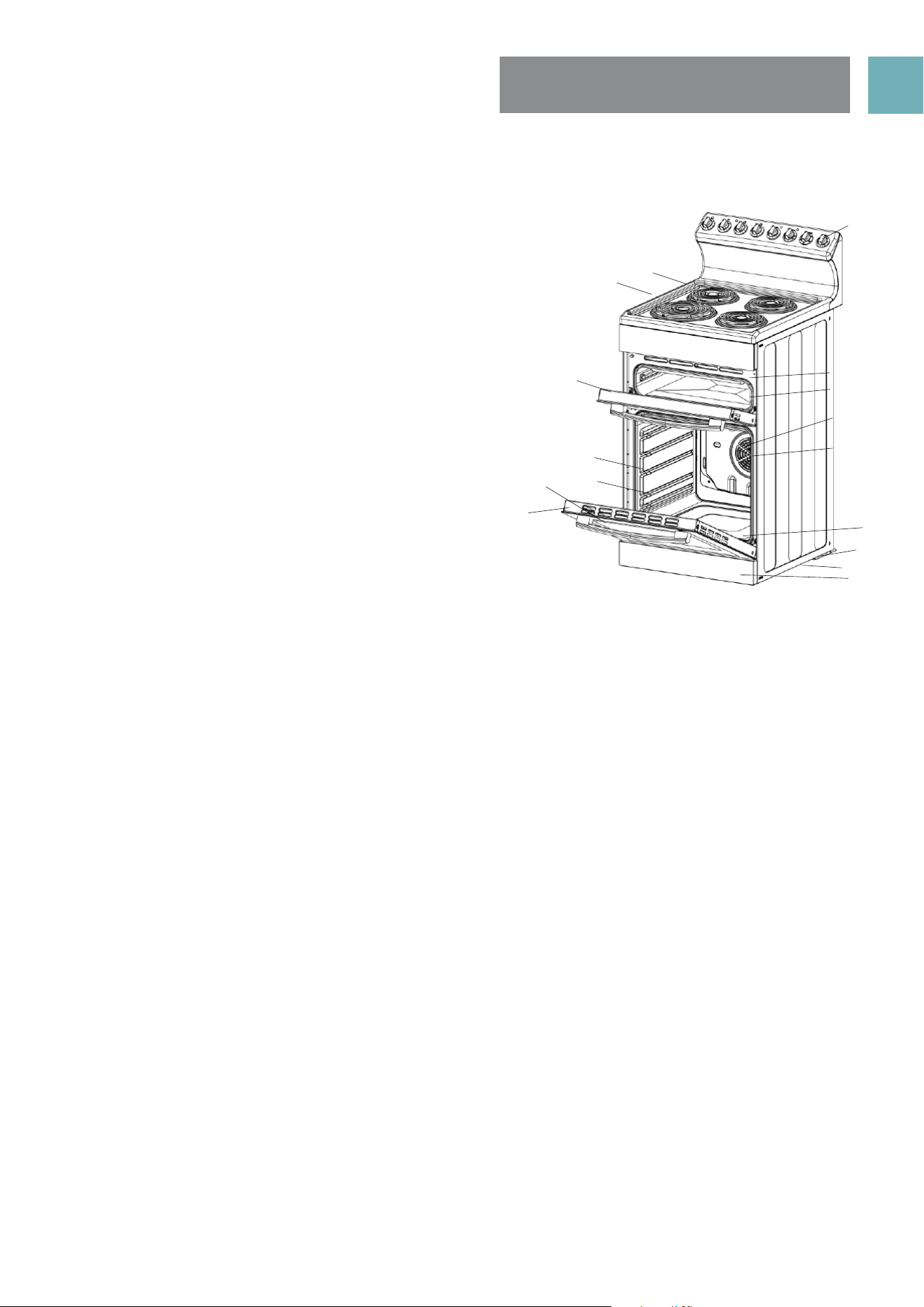
PRODUCT DESCRIPTIONS
REAR CONTROL MODELS
1. Hob (solid, coil and ceramic)
2. Heat shield (coil element models only)
3. Grill door
4. Oven shelf (2 supplied)
5. Enamelled oven baking tray (1 supplied)
6. Oven inner door glass
7. Oven door
8. Control panel
9. Grill element (inside compartment)
10. Grill tray wire rack insert (reversible to adjust
height)
11. Fan & element cover
12. Oven rear fan forced element
13. Hidden oven base element
14. Rear adjustable anti slip feet (2)
15. Anti tilt floor bracket
16. Kick panel (stability bolt located behind kick panel)
DESCRIPTION OF COOKER WITH
SEPERATE GRILL AND REAR CONTROLS
8
9
10
11
4
12
14
16
15
13
56
7
3
2
1
USER MANUALPG 7
PRODUCT DESCRIPTIONS
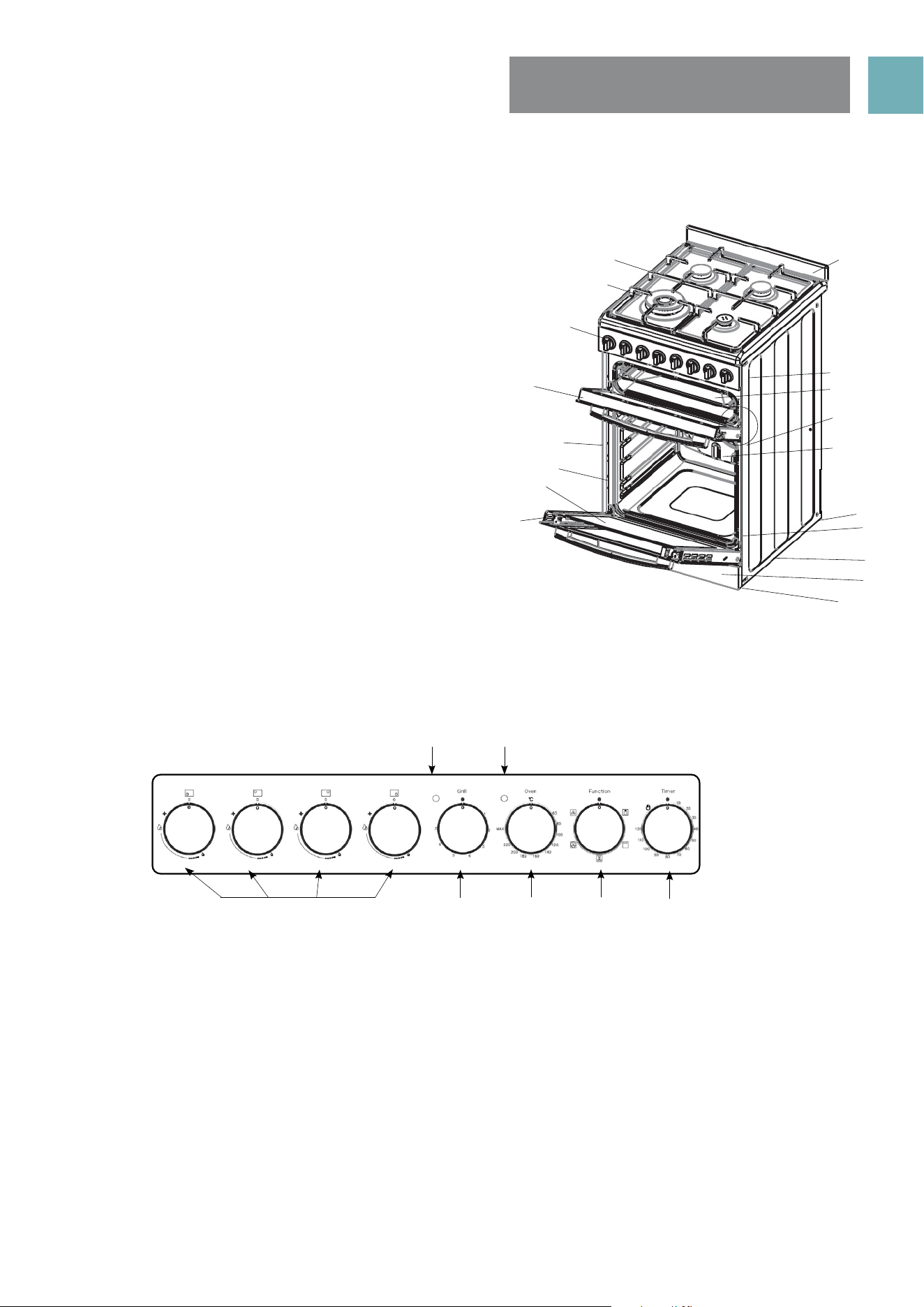
FRONT CONTROL MODELS
1. Hob (Solid, coil, ceramic and gas). Gas model supplied with
cast iron trivets and WOK adapter.
2. Gas Model - Wok burner (1) (highlighted) with removable
cap, distributor, other burners (2x semi rapid, 1x auxiliiary).
3. Control panel
4. Grill door
5. Oven shelf (2 supplied)
6. Enamelled oven baking tray (1 supplied)
7. Oven inner door glass
8. Oven door
9. Rear splash back (1 supplied)
10. Grill element (inside compartment)
11. Grill tray wire rack insert (reversible to adjust height)
12. Fan & element cover
13. Oven rear fan forced element
14. Hidden oven base element
15. Rear adjustable anti slip feet (2)
16. Anti tilt floor bracket
17. Kick panel (stability bolt located behind kick panel)
18. Front adjustable anti slip feet (2)
1. Gas burners control knobs
• Sets burner cooking temperature.
2. Grill indicator light
• Light is on when grill element is heating up, then cycles on and off to maintain temperature.
3. Oven indicator light
• Lights is on when oven element is heating up, then cycles on and off to maintain temperature.
4. Grill temperature control knob
• Adjusts grilling temperature.
5. Oven temperature control knob
• Adjusts oven temperature.
6. Oven Function control knob
• Sets oven function.
7. 120 Minute Timer
• Sets “reminder” alarm count-down time, or if oven is being used, the cooking time until oven
switches OFF.
NOTE: The gas burner control knobs have to be held down for approximately 5 seconds to ignite.
DESCRIPTION OF COOKER WITH
SEPERATE GRILL AND FRONT CONTROLS
CONTROLS
Front Control Panels: EFS54FC-DDS
2
1
5 6
7
3
4
8
9
10
11
4
12
14
16
15
17
18
13
5
6
7
3
2
1
USER MANUALPG 8
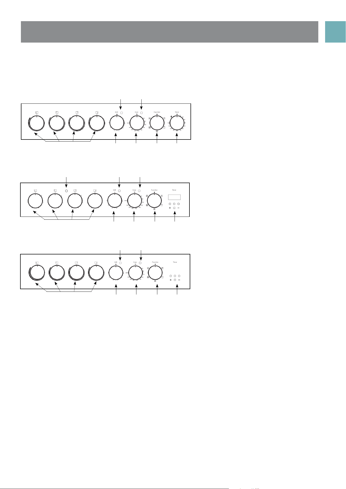
1. Radiant (coil) Hotplate Control Knob
• Adjusts temperature of hotplate.
2. Hotplate Indicator Light (where fitted)
• Comes on when a hotplate is turned on.
3. Grill Indicator Light
• Light is on when grill element is heating up, then cycles on and off to maintain temperature.
4. Oven Indicator Light
• Light is on when oven element is heating up, then cycles on and off to maintain temperature.
5. Grill Temperature Control Knob
• Adjusts grilling temperature.
6. Oven Temperature Control Knob
• Adjusts oven temperature.
7. Oven Function Control Knob
• Sets oven function.
8. Programmable Clock (where fitted)
• Sets cooking reminder times and sets automatic cooking duration and stop time
9. 120 Minute Timer
• Sets “reminder” alarm count-down time, or if oven is being used, the cooking time until oven
switches OFF.
10. Ceramic Cooktop Control Knob
• Adjusts temperature of ceramic cooktop.
Front Control Panels:
EFS54FC - DCW
Rear Control Panels
EFS54RC - DRW
Rear Control Panels
EFS54RC - DCW and EFS54RC - DCB
3
32
1
3
10 5 6 7
9
4
4
4
10 5
5
6
6
7
7
8
8
USER MANUALPG 9
USING THE OVEN
PREPARING YOUR APPLIANCE FOR THE FIRST TIME
• Please wipe out the oven interior prior to operation with warm soapy water and polish dry with a soft
clean cloth.
• New appliances can have an odour during first operation from components manufactured with the aid
of oils. It is recommended to ‘run in’ your oven before you cook for the first time. Run the an empty oven
at 180°C for approximately 1 to 2 hours. Ensure that the room is well ventilated.
• Please install oven furniture as outlined in the “Fitting Oven Accessories and Cleaning” section.
• If your appliance is fitted with solid hotplates, turn heat setting to high for 3 minutes to fully harden the
coating. When cooled, apply a thin coating of cooking oil to seal the surface.
• The grill element may have oils left on the grill during manufacture. Before you cook on the grill for the
first time, turn on for 15 minutes with 10mm of water in the bottom of the grill dish.
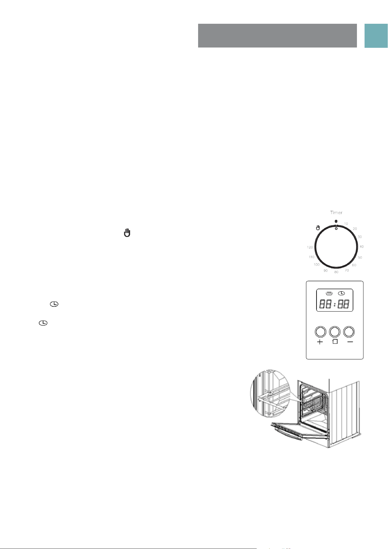
120 MINUTE TIME MODELS
If your upright cooker is fitted with a 120 minute timer you must select a cooking time or
turn the knob clockwise to the ‘ ’ symbol to operate. If either of these are not selected
the oven will not heat.
DIGITAL TIMER WITH 3 BUTTONS
If you have purchased a model fitted with a 3 button programmable timer, you must set
the time before you can operate your appliance.
• After the appliance has been electrically connected “00.00” will be displayed and
the“ ” will flash.
• To set the time, press the “–” or“+” buttons. 15 seconds after the last change, the
“ ” will disappear, confirming the time has been set.
NOTE: The clock has a 24-hour display
FITTING OVEN SHELVES
• Ensure shelf orientation is correct (refer picture).
• The shelf has a safety bar fitted to reduce the risk of dishes sliding off
the shelf, this is the rear of the shelf
• Slide into oven at an angle until raised back of shelf is past the stop
on side runners.
• Lower front of shelf and push in until stop is reached.
NOTE: The top ledge is not a shelf position
OVEN SHELF POSITIONS
• The main oven has 5 shelf positions to choose from. Position 1 is the position at the bottom of the oven
and position 5 is located at the highest point of the oven
• The 5 position side rack system can house both the standard oven shelves and baking tray.
USER MANUALPG 10
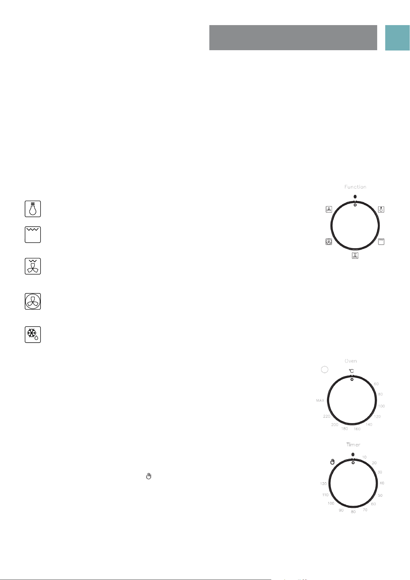
SET OVEN FUNCTION
Description of oven functions
Light
The oven light is on. No heating elements are on.
Grill
The top central heating element comes on. Suitable for grilling food or browning
food. Do not use lowest shelf position.
Fan Assisted Grill
The upper heating element and the fan come on. Suitable for grilling food without turning over and
using two shelves. Do not use lowest shelf position
Fan Forced
The rear circular heating element and the fan come on to make heat distribution more even throughout
the oven. This mode is ideal for general purpose cooking on 3 shelves at the same time.
Defrost
Only the fan operates. It is located on the back of the oven, making the air circulate at room
temperature around the food. This is recommended for the defrosting of all types of food. By using
the fan, the defrosting time is approximately halved .
OVEN TEMPERATURE KNOB
Select cooking temperature by turning the knob clockwise to the required temperature,
between 60ºC to MAX.
• If the appliance is electric the “oven indicator light”will come on when the oven is
heating up. When it goes out it means that it reached the required temperature.
The oven indicator light going ‘on & off’ during use is then normal. This means that
oven temperature is being constantly maintained at the selected level.
SET COOKING TIME
120 Minute Timer
Operating oven without Timer
• Turn knob counter clockwise to “ ” symbol. The oven will operate without use of the
timer function.
Operating oven using the Timer
• To set the timer, simply turn the knob clockwise to the required number of minutes.
The timer will automatically shut down the oven after the set minutes and the timer
will ring at the same time.
NOTE: For any time below fifteen minutes turn the knob past the fifteen then turn it back to the required
number of minutes. When the timer returns to zero, the timer gives a short ring.
USING THE OVEN
OVEN SAFETY WARNINGS
• Always follow the instructions for putting the shelves and side racks into the oven, to avoid accidents.
• DO NOT line the oven with foil, it will damage the enamel coating.
• DO NOT place cookware or anything else on the bottom of oven as trapped heat will damage the
oven enamel coating.
• DO NOT touch the hot surfaces or heating elements inside the oven.
• DO NOT use the oven door as a shelf.
• DO NOT push down or sit on the open oven door.
• DO NOT place shelves on top of upper most shelf runner as there are no stops for shelf withdrawal
USER MANUALPG 11
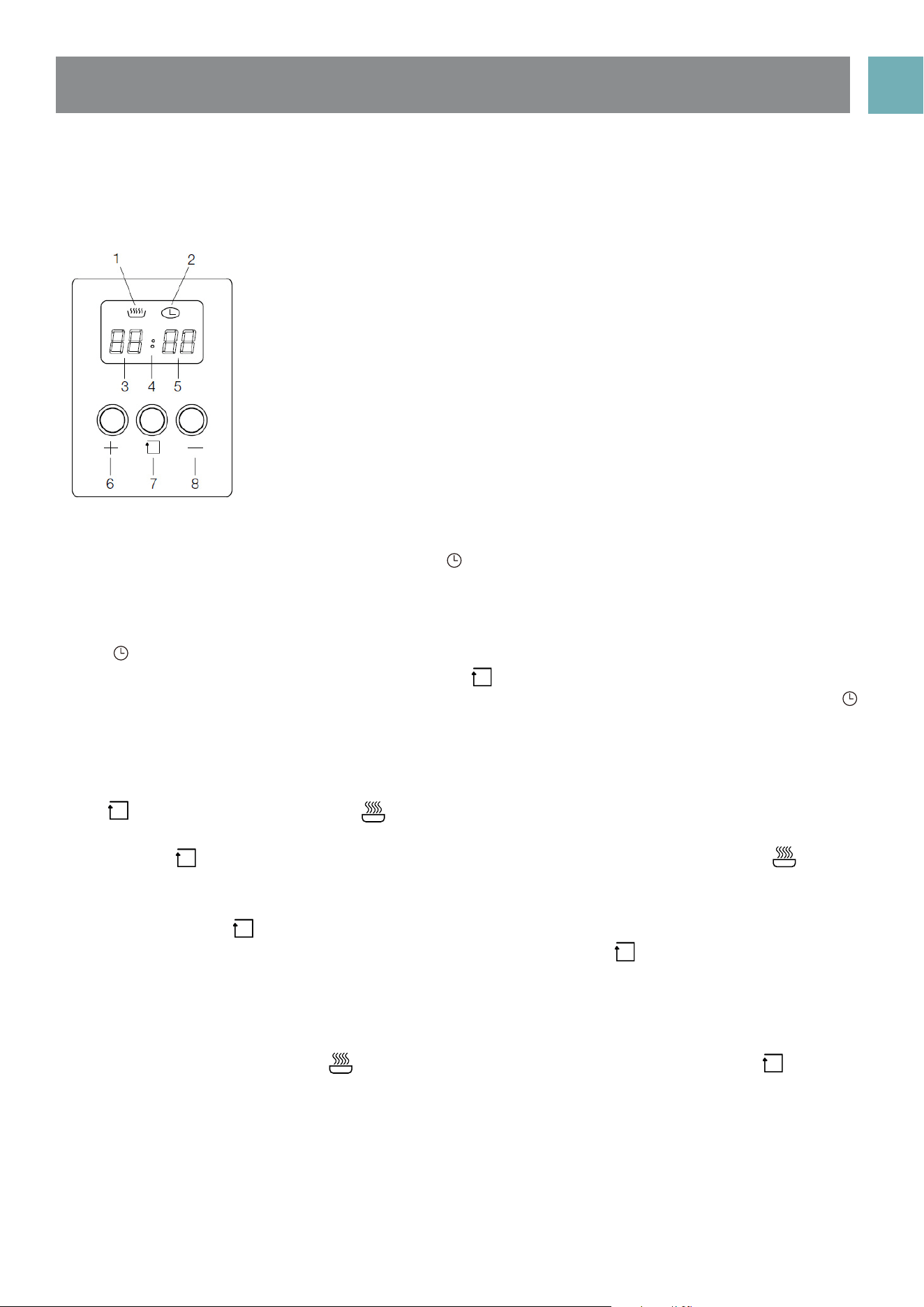
PROGRAMMABLE CLOCK
1. Heating indication
2. Clock indication
3. Hour indication
4. Second indication
5. Minute indication
6. Up
7. Set
8. Down
Starting-up procedure
After power on, the screen will display “00:00” and “ ” clock indicator will be on.
Setting the time
NOTE: Digital clock is displayed in 24 hour format
When “ ” clock indicator and hour indication are flashing, press “ + ” up key or “ – ” down key to select a
number value from (0-23) for the hour time, then press “ ”set key to change to the minute setting. Whilst
flashing press ‘ + ‘ up key or ‘ - “ down key to select a number value from (0-59) for the minute time. The “ ”
clock indicator will remain flashing for 15 seconds once the time is set and neither of the “ + ” up key or “ – ”
down keys and pressed again whilst flashing.
Setting cooking duration timer
Press “ ” selection button 3 times until “ ” heating indicator is flashing, then press “ + ” up key or the “ – ”
down key to select the cooking duration time in hours.
Then press the “ ” selection button to enter the cooking duration time in minutes setting. The “ ” heating
indicator will remain flashing for 15 seconds once the cooking duration time is set and neither of the “ + ” up
key or “ – ” down keys are pressed again whilst flashing.
Alternatively press the “ ” selection button and the oven will start cooking immediately
If duration timer setting does need to exceed 59 minutes then initially the “ ” selection button should be
pressed 4 times instead of 3 to bypass the hour duration selection.
Audible ‘End of Cooking’ buzzer
The buzzer will sound for up 60 seconds at the end of the cooking time duration that has been set has been
reached. The “ 00: 00 ” display and “ ” heating indication will flash for this period unless the “ ” selection
button is pressed. The clock will return to the time of day display when either of the above tow actions
occur.
Note
• If you press “ + ” up key or “ – ” down key for more than 3 seconds, the value will change quickly.
• When setting the Time or Cooking Duration Timer the “ : ” does not blink although will blink when in either
normal Time mode or Cooking Duration Timer is displayed.
USER MANUALPG 12
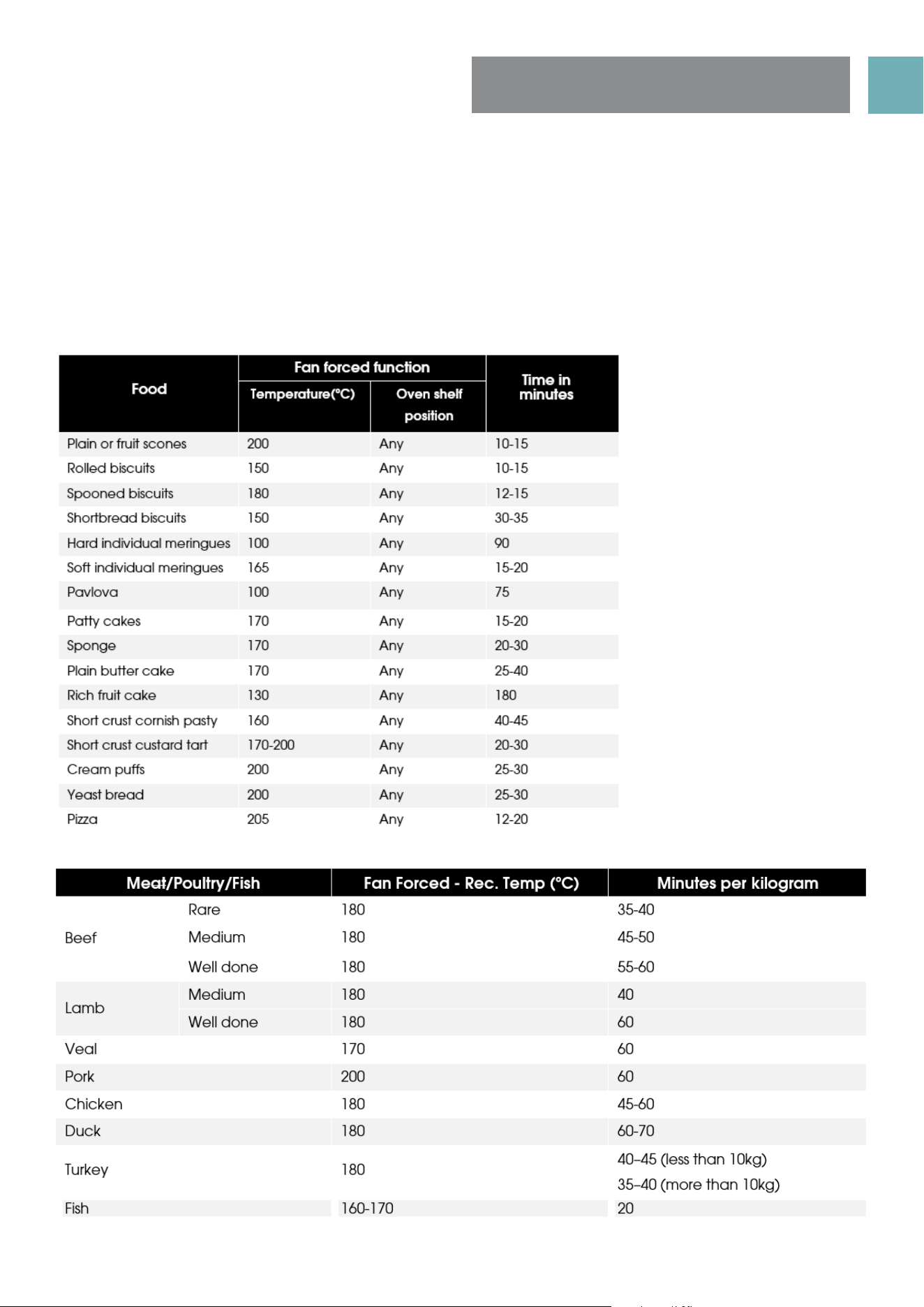
OVEN COOKING
GUIDE
The following is intended as a guide only. It is often required to set oven 10-20 degrees above or below this
guide to get the result you want. Also adjustments are needed for the cooking time to suit personal desired
results. Also you should follow the recipe guide when setting temperature and times. For best results when
baking, preheat your oven for 15-20 minutes.
USER MANUALPG 13
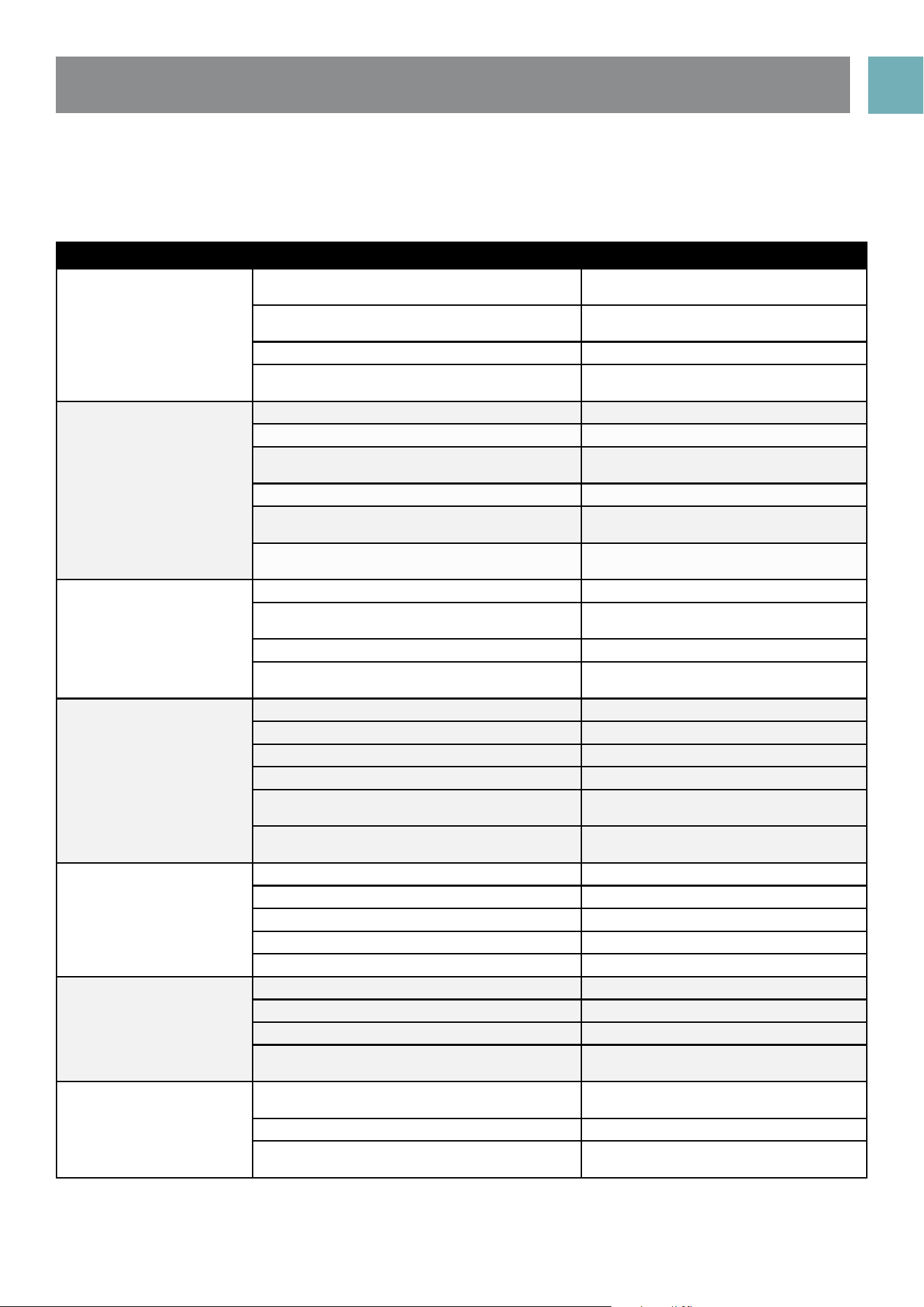
UNDERSTANDING COOKING PROBLEMS
NOTE: Condensation on oven door is normal, especially when kitchen is cold. Also spacing and size of food
on trays and the number of baking dishes in the oven can affect air circulation.
Problem Causes What to do
Uneven cooking Incorrect shelf position Select shelf that puts food in centre of
oven
Oven tray too large Remove oven tray. Use smaller trays or
dishes
Trays not in centre Put trays in centre
Oven fan causing uneven browning or small
cakes to lean over
Rotate food during cooking, or use
Conventional Mode (i.e. no fan)
Baking products too brown
on top
Oven not preheated Preheat the oven
Baking tins too large (diameter) for recipe Use correct size tins
Fan-forced mode with oven temperature too
high
Check recipe. Reduce oven
temperature by 10-29 or more
Cooking time too long Next time, shorten cooking
Baking tins not evenly spaced Stagger baking tins at least 3cm
between tins and the oven walls
Items to be cooked are not evenly sized or
spaced in trays
Make into same size and shape and
spread evenly over trays
Baking products too brown
on bottom
Baking tins too large Use correct size tins
Baking tins are dark metal or glass Change to shiny, light tins or lower the
temperature by 10-20 degrees
Food to low in oven Cook one shelf higher
Oven door opened too frequently during
baking
Don’t open the oven door until at least
half the ooking time has passed
Cakes have a cracked
thick crust
Baking temperature too high Lower the temperature
Oven tray blocking heat (below themostat) Use higher shelf position for oven tray
Baking temperature too high Lower the temperature
Food too low in oven Cook one shelf higher
Cake batter over mixed Mix just long enough to combine the
ingredients
Baking tin too deep or wrong size Check size of tin and use
recommended size
Bked products are pale,
flat and under cooked
Baking tins dark Change to shiny light tins
Baking temperature too low Raise the temperature
Food too low in oven Cook one shelf higher
Baking time too short Increase cooking time
Incorrect baking tin size Use correct sie tin
Cakes fallen in centre Baking temperature too low Raise the temperature
Baking time too short Increase cooking time
Proportions of ingredients incorrect for recipe Check recipe
Opening door too early during baking Do not open door until the last quarter
of cooking time
Roast meat and potatoes
not browning in fan oven
Poor hot air circulation Elevate food onto a rack to allow air
circulations
Oven temperature is too low Increase temperature to 200-22-
Not long enough in oven Continue cooking for another 15+
minutes
USER MANUALPG 14
Grill safety warnings
• Always turn off the grill immediately after you have finished cooking and pull drawer out or remove grill
tray otherwise fat left in the tray in the hot grill compartment will continue to smoke or could catch fire.
• Wash grill tray & grill insert after every use.
• Grill insert rack can be inverted…..to provide 2 different settings for the distance from top of food to the
grill element.
• DO NOT line the grill rack with foil.
• DO NOT leave the grill unattended and check progress of cooking every 1 – 2 minutes (especially
bread).
• DO NOT try to grill place food more than 25mm thick. Food may catch fire. Trim excess fat from fatty
type meats to reduce any risk of fire.
• Do not store flammable materials near the grill.
Using the grill
• Ensure grill wire rack is turned over to ‘high’ position in the enamel grill tray for toast, food less than 20mm
thick, or turned over to ‘low’ position for food 20-30mm thick.
• Turn the grill control knob to adjust the temperature to get the desired result. Eg, toast 4 or 5, meat 6 or 7.
• Preheat the grill. After 3 minutes, open the grill EPPS and place food onto grill rack insert.
• Close the grill drawer.
• In the process of grilling, PQFO UIF HSJMM EPPS every minuteT to check progress of toast, every 3 minutes
for meats.
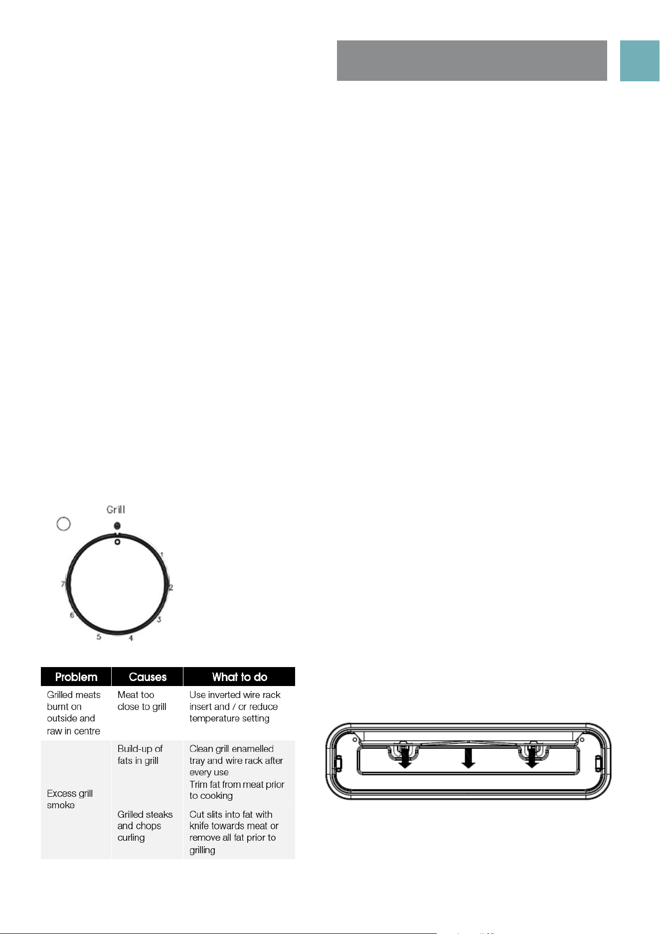
USING THE GRILL
Grill Information
• The grill function is suitable for tender cuts of meat, steak, chops,
sausages, fish, bread, cheese toasties and other quick-cooking foods.
• Preheat for 3 minutes.
• Place food in the grill after pre-heating is finished
• The grill door must be closed during grilling.
USER MANUALPG 15
USING THE HOTPLATES
OF YOUR COOKER
Ceramic hotplates
• DO NOT use if the ceramic glass top is cracked or broken.
• DO NOT leave aluminium foil on the hot ceramic hotplates (permanent damage will occur)
NOTE: Stored heat in the hotplate can be used for the last few minutes of cooking. Simply turn off the
control.
Choosing Cooking Pots
• Look at this diagram below which shows you which cooking pot and pans to use on the hotplates and
which ones that should not be used.
• After switching off, this light will continue to glow until the temperature of the hotplate drops below 60°C
Hotplates safety warnings
• Do not use pots and pans which are unsteady, as these could overbalance.
• Do not use mats, heat diffusers or wok stands. These will cause a temperature build-up which can damage
the cook top.
• DO NOT turn on hotplates if there is no pot or pan on hotplate or if they do not contain food or liquids in
them.
• Do not let cooking pots overhang sides or front of hob get too close to the hotplate control knobs.
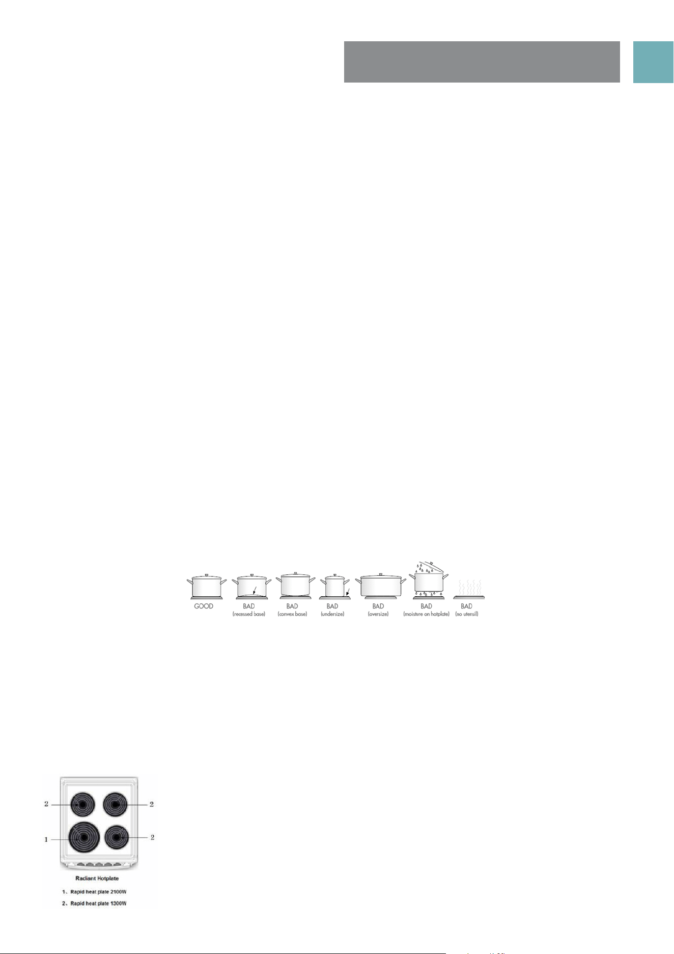
Choosing cooking pots and pans
Look at this diagram below which shows you which utensils to use on the hotplates and which utensils should
not be used.
• Always use pots and pans with flat bottoms. Uneven or thin bottoms will waste energy and cook slowly.
• Always use pots and pans which are slightly larger than the hotplate. Small pans waste energy.
• Always put dry pots and pans on the hotplates.
• Do not use pots and pans which are too large. Pans which overhang the hotplate more than 50mm can
damage the hob.
• Always use pots and pans with flat bottoms.
• Uneven or thin bottoms will waste energy and cook slowly.
• Always use pots and pans which are slightly larger than the hotplate. Small pans waste energy.
• Always put dry pots and pans on the hotplates.
• Do not use pots and pans which are too large. Pans which overhang the hotplate more than 50 mm
can damage the hob or surrounding surfaces.
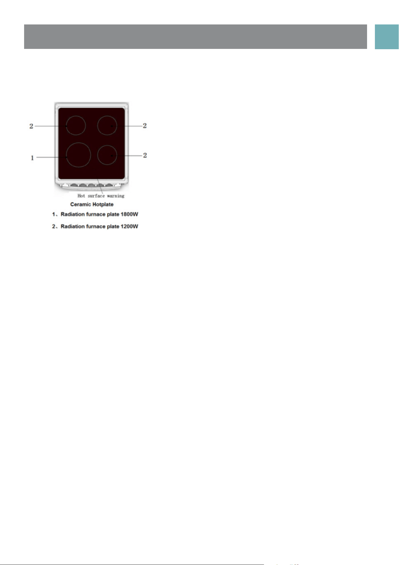
Using the hotplates of your electric cooker
• Check the hotplates on your cooker against the diagrams below before you use your cooker for the first time.
Radiant hotplates
• The high-speed radiant hotplates heat rapidly from a cold start.
• The radiant elements can be unplugged and the trim rings can
be removed for cleaning the spillage bowls
USER MANUALPG 16
• DO NOT use the cooktop if the glass is cracked.
• Contact the service department immediately to have this repaired.
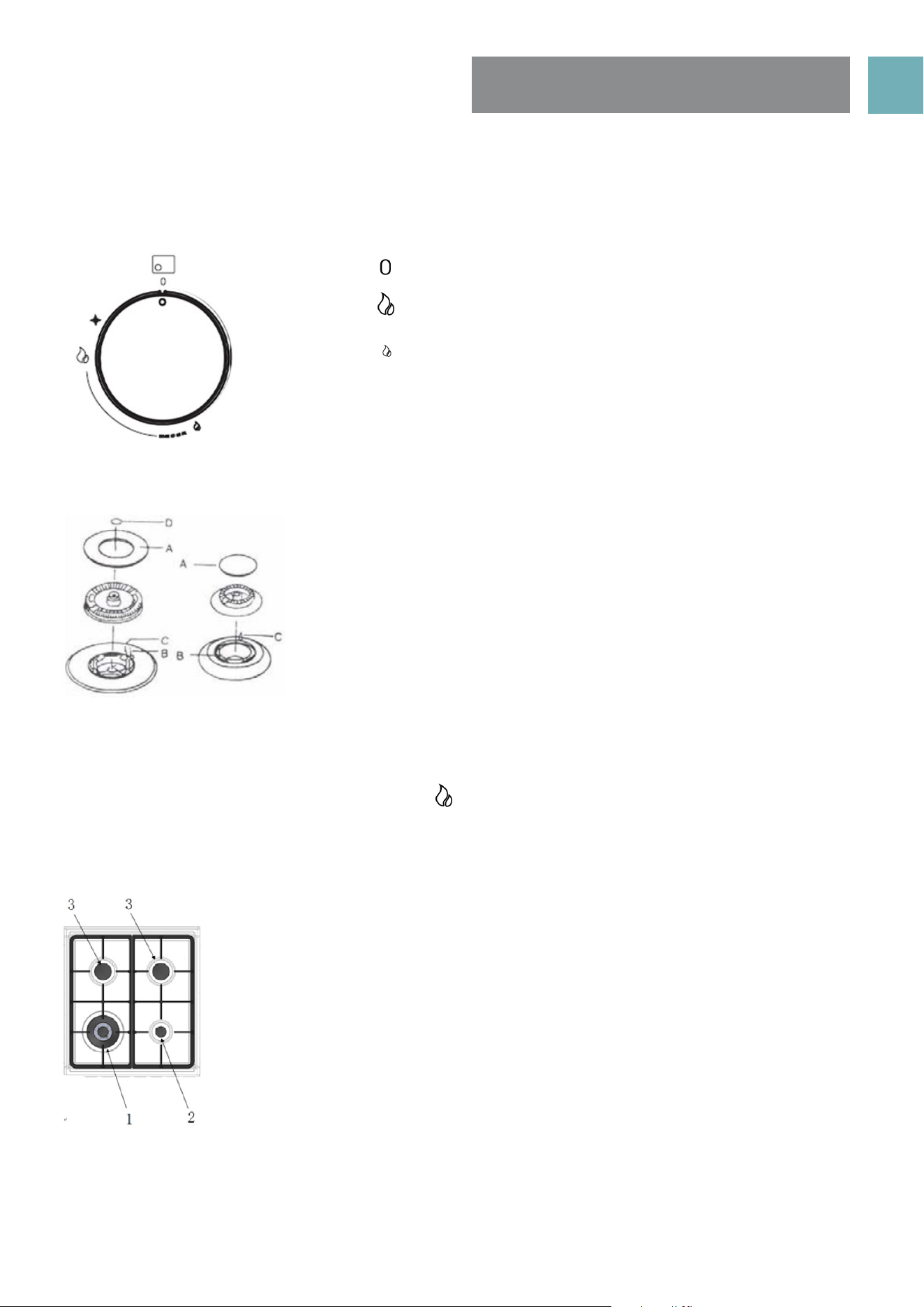
• The ceramic cooktop is made from ceramic glass, a tough, durable material that withstands heating
and cooling without breaking.
• However, it must be remembered that as it is glass, it may break.
• The smooth glass surface has a pattern to show where the elements under the glass are located.
• When a hotplate is on, the hot surface warning light will come on. After switching off, this light will
continue to glow until the temperature of the hotplate drops below 60°C.
Care of ceramic glass surface
• Ensure that spills from sugary substances are cleaned as soon as possible after spillage as sugar can
damage the ceramic glass surface over time.
• A glass scraper should be used to remove burnt on and very stubborn spills created during cooking,
• Warm soapy water, followed by wiping with a dry soft cloth is fine for daily cleaning.
• Periodic care, approximately once a month, should be carried on the ceramic glass surface. We
recommend the use of Hillmark ‘Cerapol’ ceramic cooktop cleaner to remove stubborn stains.
• To maintain and protect the ceramic glass surface over time Hillmark ‘Ceraseal’ ceramic cooktop
protector is recommended. This silicon based product creates a thin film of the ceramic glass surface.
• Scratches can appear on the glass surface although do not effect the use of the cooktop.
Ceramic hotplates
USER MANUALPG 17
USING THE GAS
BURNERS
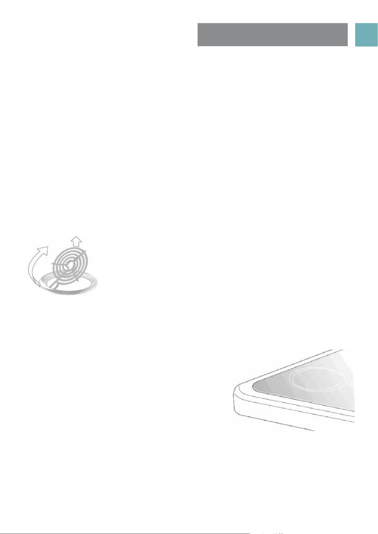
The hob control knobs
The symbols on the control knobs mean the following:
No gas flow
Maximum gas flow
Minimum gas flow
All operating positions must be set between the maximum and
minimum flow settings, and never between the maximum setting
and the closed position.
Introduction to the burner
A Burner cap
B Ignition plug
C Thermocouple
D Wok burner cap
Hotplate Ignition
To light these hotplates:
1. Choose the hotplate you want to use.
2. Push in burner control knob and rotate to “ ”.
3. Hold control knob for 2-3 seconds, them release and rotate knob to adjust the flame height. If flame
goes out, the knob was not held in for suffcient time; repeat step 2.
Burner
1. Wok burner
• Used for fast heating.
• Used with WOK, large size pots and pans.
• For rounded bottom woks use WOK adapter.
2. Small Burner
• Used for simmering.
• Used with small pots and pans.
3. Semi-rapid Burner
• Used for normal cooking.
• Used with middle size pots and pans.
To conserve gas, place the pan centrally over the burner and adjust the flame so that
it does not go past the edges of the cookware.
USER MANUALPG 18
CLEANING THE COOKER
SAFETY WARNINGS ABOUT CLEANING
• Always make sure that the cooker is turned off before cleaning.
• Always clean cooker immediately after use.
• Do not use steam cleaners. These may cause moisture build-up.
• Do not use caustic- based cleaners. These will damage aluminums parts, and remove enamel gloss.
CLEANING THE ENAMEL
• Keep enamel clean by wiping it with a soft cloth dipped in warm soapy water.
• Rub difficult stains with a nylon scourer or creamed powder cleanser.
• Do not use abrasive cleaners, dry powder cleaners, steel wool or wax polishes.
• If you use an oven cleaner, then follow the instructions on the product carefully.
CLEANING THE CONTROL PANEL
• Make sure control knobs are in off position.
• Clean the control panel by wiping it with a soft cloth dipped in warm soapy water and squeezed dry.
CLEANING THE ELECTRIC COOK TOP
Radiant hotplates
These coiled hotplates are self cleaning. To clean the trim rings, lift front of element and remove trim ring.
Then wash in warm, soapy water. To clean the spillage bowl, lift element and pull out of socket. Remove
spillage bowl and wash in warm soapy water. DO NOT PUT ELEMENTS IN WATER!
Ceramic hotplates
• Remove all spilt food with the razor blade scraper supplied
while the hotplate is still warm turned off) –NOT HOT.
• If aluminium foil, plastic items or foods with a high sugar
content melt onto glass, use the razor blade scraper to
remove immediately before the hotplate has cooled,
otherwise pitting of the surface may occur. High sugar content
foods include jam, fruit, carrots, tomatoes and peas.
• When the ceramic hotplate has cooled, wipe clean with
dishwashing detergent on a damp cloth.
NOTE: Do not use abrasive sponges or scourers, oven sprays
or stain removers on ceramic hotplates. These may damage,
scratch or stain the ceramic cook top. Any pitting, staining or scratching will not be covered by warranty.
USER MANUALPG 19
FITTING OVEN ACCESSORIES
& CLEANING
Cleaning the Gas Hob
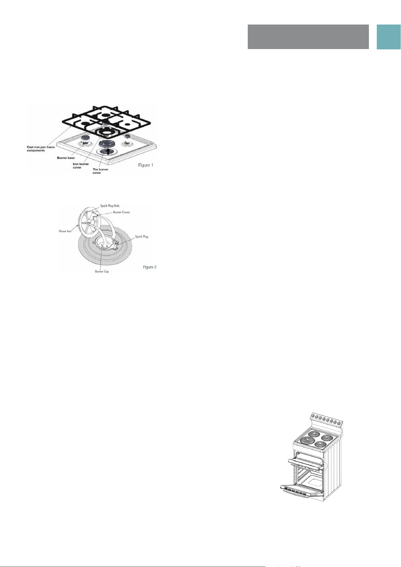
Removing the trivets (Refer Figure 1)
Refitting the burner crowns and caps
• The burner crown must be fitted correctly into the burner cup or damage will occur during operation.
• To do this, ensure that the 2 ribs on either side of the spark plug hole are positioned into the 2 slots on the
burner cup. (See figure 2).
• The burner cap is simply positioned over the top of the burner crown.
NOTE: When the burner is correctly fitted it will sit level on the hob. If ignition is difficult or fails after
cleaning, or the flames are not even around the burner, then either burner parts are not dry / parts have
not been positioned correctly or incorrect cap is fitted.
• The burner caps and crowns are removable for cleaning.
• Flame port blockage should be removed by means of a
match stick or brush.
• If the caps, crowns and cups are heavily soiled, use a non-
abrasive cleaning compound.
• Do not clean them with abrasive or caustic type cleaners, or
put in a dishwasher as they will be damaged.
Cleaning the grill compartment
• Pull the grill tray out.
• Clean the sides an bottom of compartment with hot soapy water.
• If stronger action is needed use a non abrasive cleaner applied with
a nylon scourer.
Cleaning the Oven
• Open the door fully.
• Remove oven shelves and side racks.
• Clean in hot soapy water.
• Thoroughly dry with a soft cloth to remove excess water that may be
present.
• The trivets locate in the recessed area of the hob.
• They can be removed for cleaning by carefully lifting them
from the hob.
• Clean by washing in warm soapy water. Dry thoroughly.
• Take care when replacing the trivets as dropping them
onto the hob may damage the enamelled surface.
USER MANUALPG 20
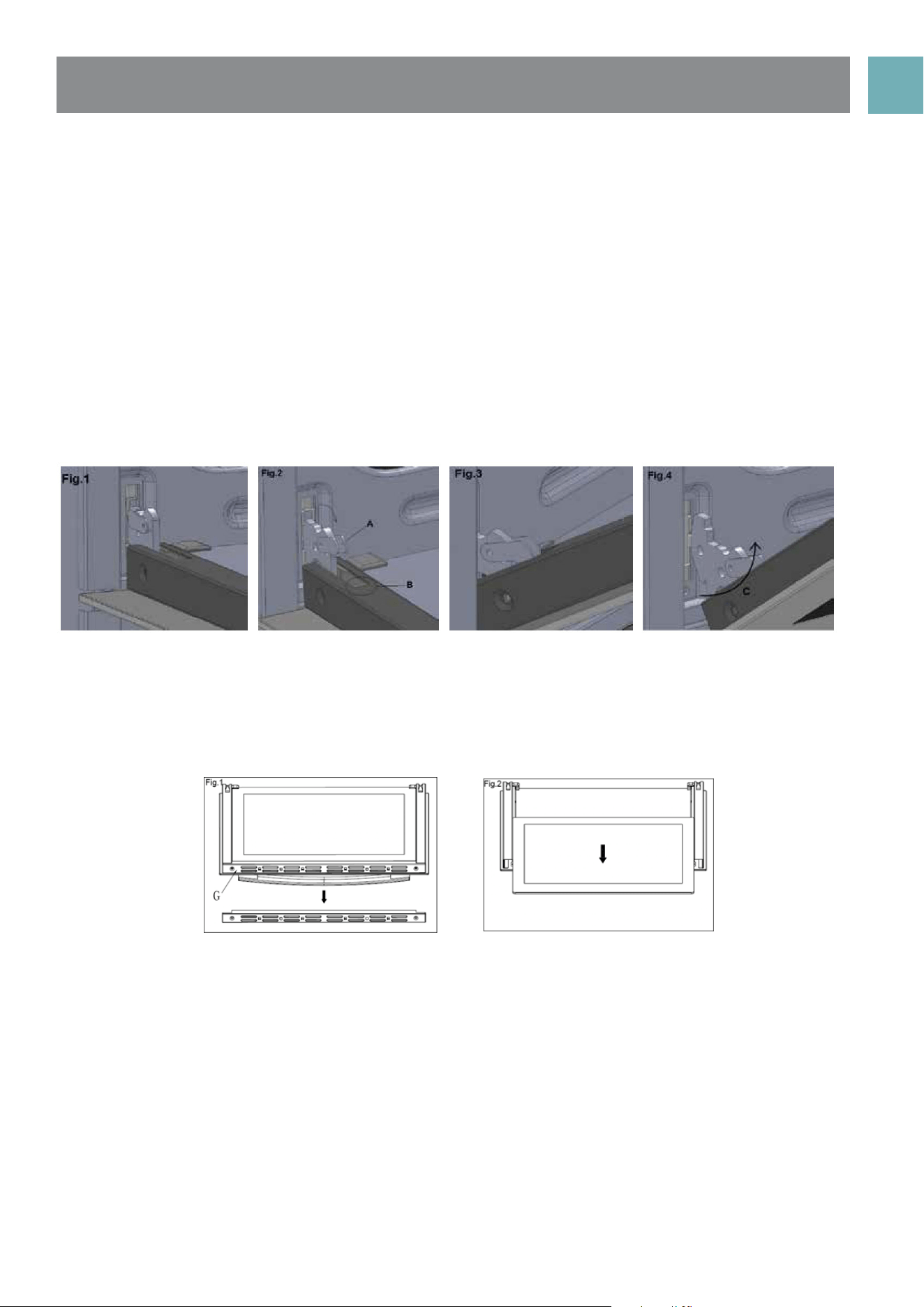
CLEANING THE OVEN DOOR / HOW TO REMOVE THE OVEN DOOR
For a more thorough clean, you can remove and disassemble the oven door. Proceed as follows:
• Open the door to the full extent (fig. 1)
• Open the lever A completely on the left and right hinges (fig. 2)
• Hold the door as shown in (fig. 3) approximatley 30 degree angle upwards
• Gently close the door (fig. 3) until left and right hinge levers A (fig. 2) are hooked to part B (fig. 2) of the
door
• Withdraw the hinge hooks from their location following arrow C (fig. 4)
• Rest the door on a soft surface, to reduce risk of damage to the door
• To replace the door, repeat the above steps in reverse order
Removing the Inner Pane of Glass
• Triple Glazed oven door: Remove the top frame (G) by unscrewing the 2 screws, located on the left and
right sides
• Gently pull out the inner pane of glass (fig. 2). Also remove the centre pane of door glass, not shown here
• Clean the glass panes with an appropriate cleaner. Dry thoroughly, and place on a soft surface.
• Now you can also clean the inside of the outer glass.
Cleaning the door glass
• Clean the glass door using non-abrasive products or sponges and dry it with a soft cloth.
• Do not use the oven without the inner door panes fitted correctly. When re-fitting inner glass door panes
ensure they go back in facing the same way they came out. The doors are coated with a very slight
reflective coating to reflect the heat back into the oven cavity and keep the outer door cooler to
touch.
• Do not use harsh abrasive cleaners or sharp metal scrapers to clean the oven door glass since they can
scratch the surface, which may result in shattering of the glass.
USER MANUALPG 21
INFORMATION ABOUT
THE COOLING FAN
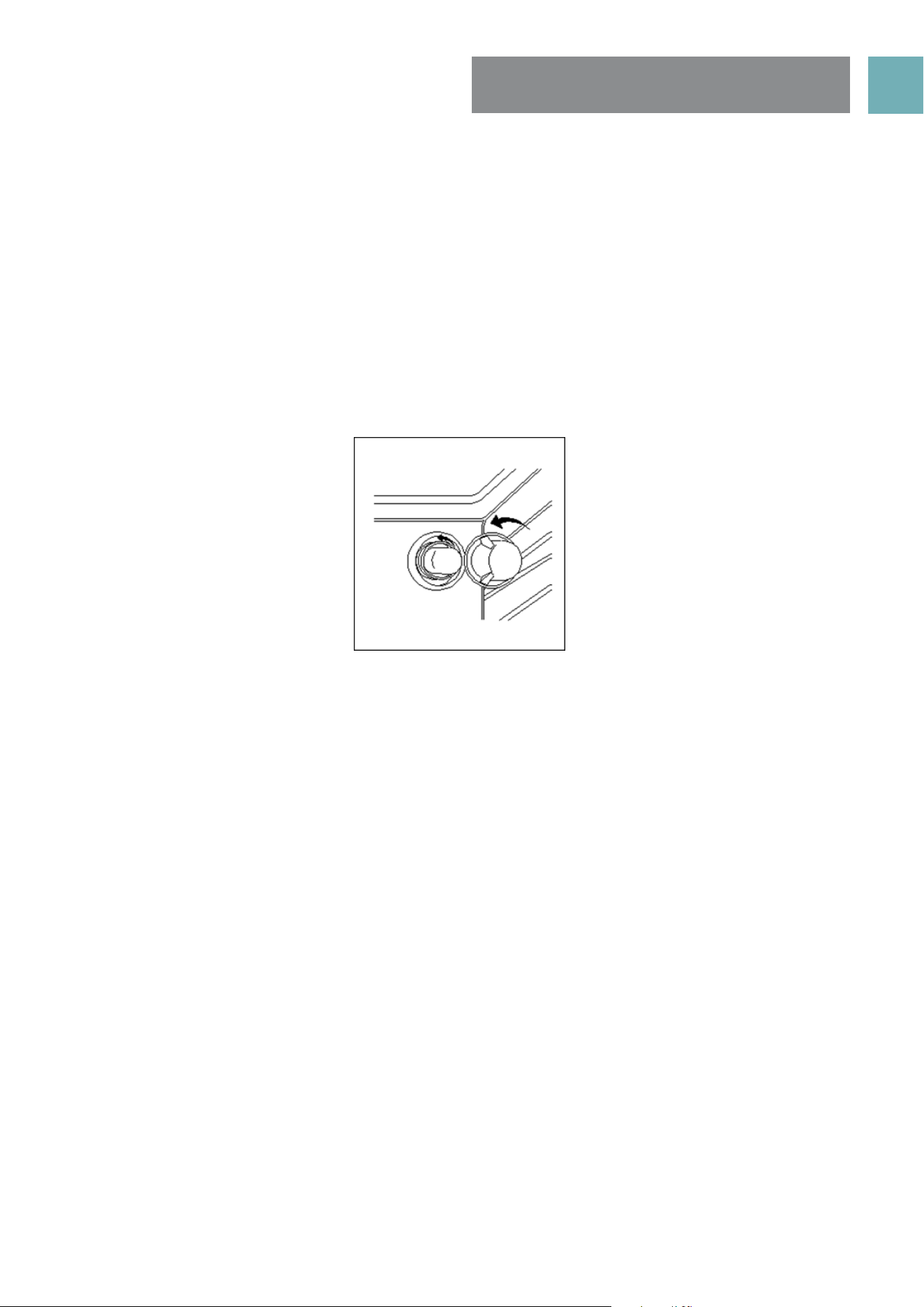
REPLACING THE OVEN LIGHT
NOTE: Your cooker is fitted with a cooling fan that will run after the oven has been turned off.
The reduce the time of the cooling fan running time it is suggested to open door ajar to assist in cooling
down of oven.
Ensure that the appliance is switched off before replacing the lamp to avoid the possibility of electric shock.
• Disconnect the oven from the power supply at the fuse-box by means of the switch used to connect the
appliance to the electrical mains.
• Remove the glass cover of the lamp-holder by rotating anti-clockwise
• Remove the lamp and replace with a lamp resistant to high temperatures (300°) with the following
characteristics:
» Voltage: 220-240V
» Wattage: 25W
» Type: E 14
• Replace the glass cover. Reconnect the appliance to the mains power supply.
USER MANUALPG 22
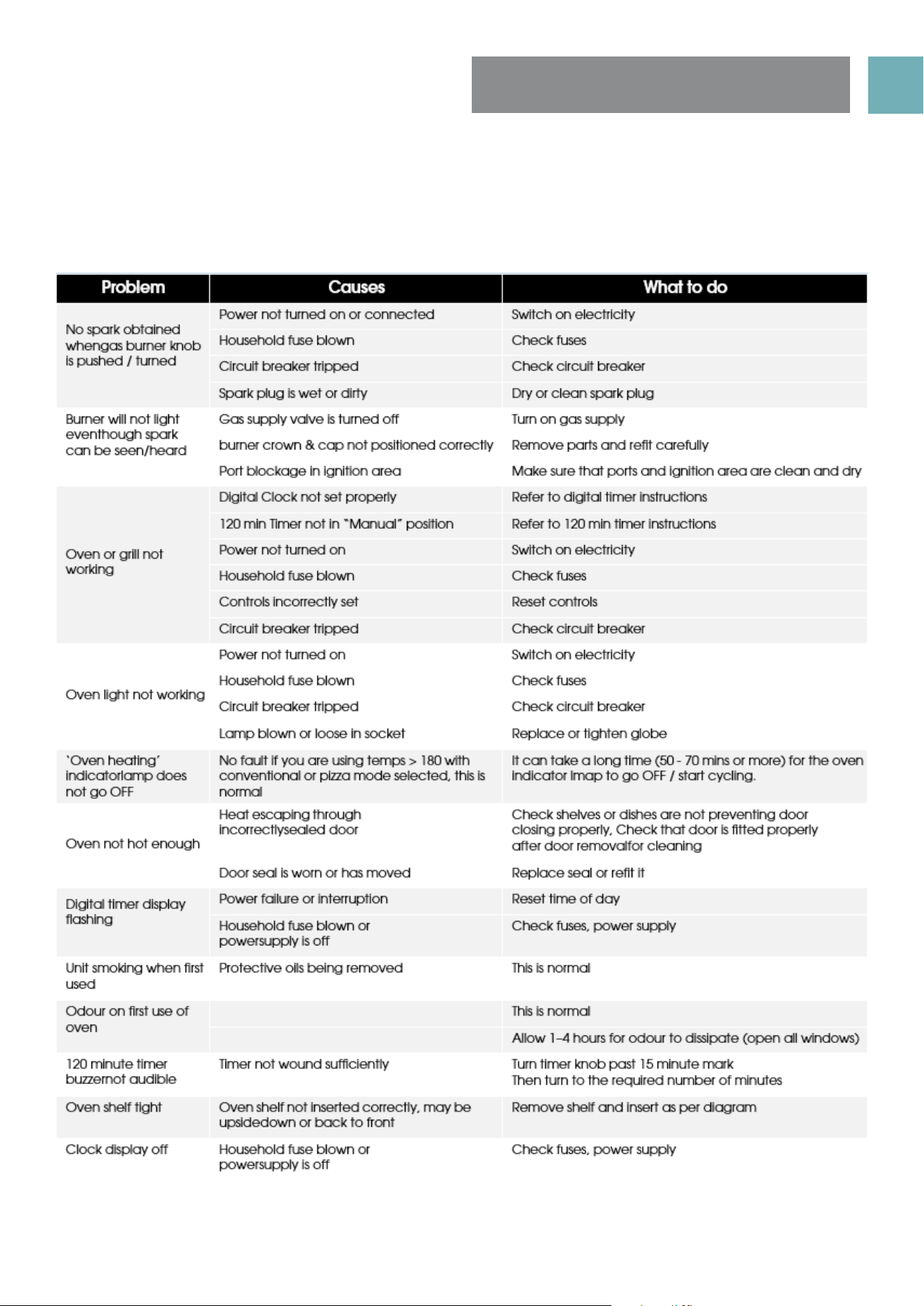
SOLVING PROBLEMS
Note: Only Euromaid Authorised service agents should carry out servicing otherwise warranty may be void.
If you have a problem with your appliance, check the table below before calling service. You may be able
to avoid a service call by and avoid unnecessary inconvenience and expense. For cooking problems, refer
to Handling Baking Problems.
USER MANUALPG 23
INSTALLING COOKER -
POWER CONNECTIONS
FITTING A POWER SUPPLY CABLE
WARNING: Installation MUST ONLY be carried out by a qualified approved installer, ie. an Electrician.
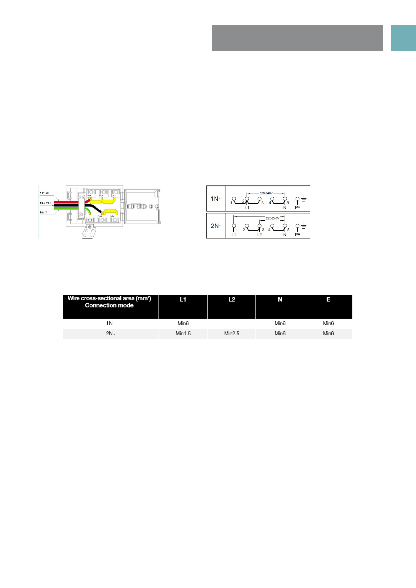
Connecting appropriate power supply ` terminal board/ connector block:
NOTE: REFER to TECHNICAL tables at the rear of this manual for correct rating for your corresponding
model purchased.
• Using a screwdriver, prize open tabs of the Terminal board cover.
• Remove the wire clamp screw.
• Fasten the wires beneath the corresponding screw heads, using brass ‘bridge’ for single phase supply.
• Fasten cable clamp and close the cover of the terminal board.
• The AC power supply should be 220-240V, 50-60Hz.
WARNING: Connect the power cord must be in accordance with the instructions listed in the table below
Connecting the supply cable to the mains
Install an approved circuit breaker with a minimum contact opening of 3 mm, between the appliance
and the mains fuse box. The circuit breaker should be sized according to the load and should comply with
current regulations (the earth wire should not be interrupted by the circuit breaker).
The supply cable should be positioned so that it does not reach a temperature of more than 50ºC with
respect to the room temperature, anywhere along its length Before switching fuse ON in meter-box check:
• Earth continuity. The electrical safety of this appliance can only be guaranteed if the cooker is correctly
installed and earthed, in compliance with regulations on electrical installations.
• The electrical capacity of the system and sockets will support the maximum power of the appliance, as
indicated on the data plate
• Go to section 19 “Installing your new cooker”
NOTE: All Upright cookers must comply to local regulations to Australian Standard AS/NZS 3000:2007
guidelines. Qualified Electrician will have a copy of these guides that MUST be adhered to.
USER MANUALPG 24
INSTALLING THE GAS
COOKER
Unpacking
Do not fit the burner crowns, burner caps and trivets until after the
cooker has been installed.
Checking gas pressures
Before installation check that the cooker is suitable for the gas supply.
To do this check the gas type on the carton sticker or on the data
plate behind the bottom of the oven door. If the cooker is required to
be used with LPG, the supplied conversion kit must be used.
The following shows the supply and operating pressures for various
gas supplies.
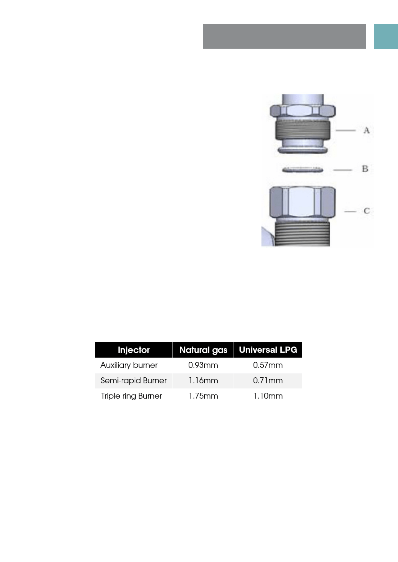
Operate pressure at appliance test point:
1.00 KPa (Natural gas); N2.75 KPa (Universal LPG gas)
The following table shows the injector sizes for each burner.
Connection to the gas supply
• The gas Connection must be made in accordance with the local standards.
• When installing, fit a safety tap at the end of the pipeline. The appliance leaves the factory tested and
set for the type of gas indicated on the plate inside the bottom guard, close to the gas connection
pipe. Make sure that the type of gas to be supplied to the appliance is the same as that shown on the
plate.
• For maximum efficiency and minimum consumption, make sure that the gas supply pressure complies
with the values shown in the gas used is different from that specified (or variable).a suitable pressure
regulator must be installed on the supply pipeline.
Procedure
Make the connection to the gas system using a rigid metal pipe and regulation unions, or with a stainless
steel hose complying with the local standard. If metal hoses are used, take care that they do not come into
contact with mobile parts and are not crushed.
When making the connection, take care not to apply stresses of any kind to the appliance.
Read these points before connecting to the gas supply;
• The gas connection point is a 1/2” BSP external thread located at the rear of the appliance as shown in
the Rear View.
• A regulator is supplied for natural gas appliances which must be fitted in the supply line to the
appliance. For LPG the supplied brass Test Point Adapter / Fitting must be fitted to the supply line.
• It is recommended to fit the regulator or test point fitting to the appliance connection point, then fit
either hard piping or a flexible connection from the regulator or test point fitting to consumer hard
piping. Ensure installation allows withdrawal of appliance. For flexible hose installation AS/NZS 5601.1
clauses 5.9 and 6.10.1.9 must be followed.
USER MANUALPG 25
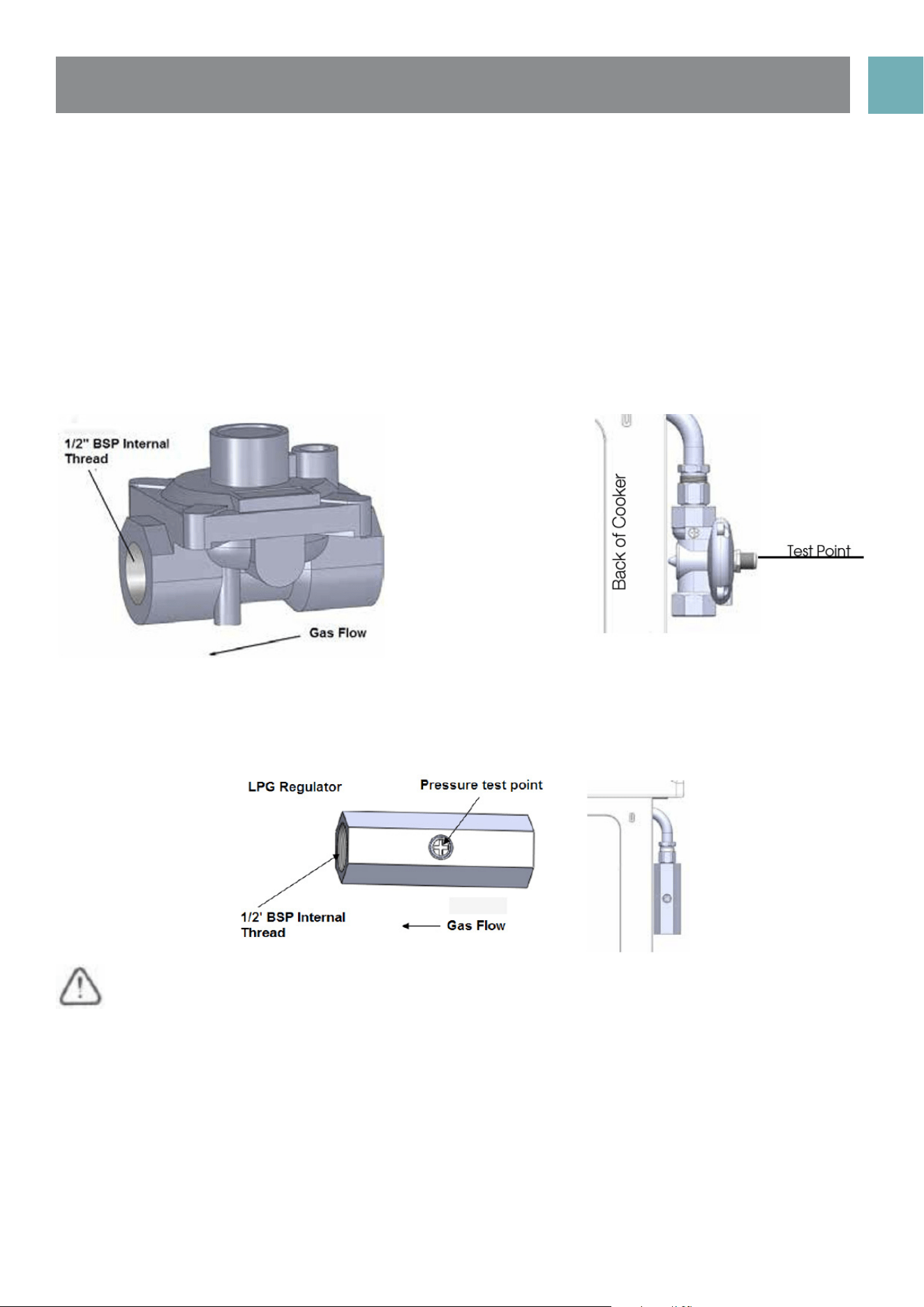
Operation on natural gas
Read these points about operation on NG/SNG and look carefully at the diagram:
• The appliance regulator provided must be orientated to give access the manometer test point.
• The arrow showing the direction of the flow must be facing the correct way from gas source into the
cooker.
• The regulator has a 1/2”BSP internal thread at inlet and outlet
NG regulator
Operation on Universal LPG
An inlet fitting with pressure test point is provided. The inlet fitting has 1/2" BSP internal thread for both inlet
and outlet.
The inlet fitting must be orientated so that the pressure test point is accessible.
When the installation is complete, always check that all the unions are absolutely tight using a soapy
solution. Never use a flame to make this check.

USER MANUALPG 26
NOTE: You must test the cooker after installation, before you hand it over to the customer. You must have a
manometer and a connecting tube.
Checking gas supply
• Check the manometer zero point is correct.
• Connect the manometer to the cooker pressure test point. This is located on the NG regulator or LPG inlet fitting.
• Turn on the gas supply and the electricity (if applicable) and try to ignite the gas.
NOTE: It will take additional time to light the gas for the first time as air needs to be purged from the pipes.
• Check the operating pressure for the particular gas type (see table).
For LPG cookers
• Adjust or replace the regulator on the gas bottle if necessary (this may be remote from the cooker).
For Natural Gas cookers
• Regulators are supplied pre-adjusted and configured by the component maker for use with Natural Gas.
The appliance installer is not required to make an adjustment to obtain the correct outlet pressure setting.
• An arrow on the base of the regulator indicates the direction of gas flow when the inlet and outlet of
the regulator are orientated correctly. When the regulator has been fitted check for leaks from the
connections with soapy water.
Checking the Function of the Regulator
With the appliance operating check the outlet pressure:
• When all burners of the appliance are operating at maximum,
• When the smallest burner of the appliance is operating at minimum.
Under these conditions the outlet pressure should not vary from the nominal outlet pressure of 1.0kPa by more
than ±20% of the nominal outlet pressure (±0.20kPa for Natural Gas).
If the regulator appears to not be performing satisfactorily then check the following points.
• If the outlet pressure is consistently too low then the inlet pressure may be too low and adjustment of an
upstream regulator may be needed, or an upstream regulator or valve with insufficient flow capacity may
be present in the gas supply line. If this is suspected then it may be necessary to repeat the checks whilst
measuring both the inlet and outlet pressure to determine if the inlet pressure is in the range 1.13 – 5kPa.
• Check that the regulator has been fitted to the gas supply line in the correct orientation, the arrow on
the base of the body indicates the direction of gas flow. Once these checks have been completed, if
the regulator still fails to perform in a satisfactory manner it should be replaced.
Testing the cooker features
Observe the flame appearance on each burner. If it is much smaller or larger than expected, then the
injector size needs checking.
When maximum flame appearance is correct, then check the turn-down setting on each burner. If the
settings appear to be incorrect, proceed as follows:
• Adjust the bypass screw mounted on the body of each hotplate control cock. This is accessible when
the control knob and the control panel are removed.
• Check the ignition on all burners both separately and in combination.
• Check the operation of the electrical components, if applicable.
• If you are satisfied that the cooker is operating correctly, then turn it off and show the customer how to
use it. Make sure you ask the customer to operate the clock and controls.
NOTE: If the cooker cannot be adjusted to perform correctly, then inform the customer of the problem and
put a warning notice on the cooker. If the problem is dangerous, then disconnect the cooker. If there is a fault,
then the customer should be advised to contact the manufacturer’s local service organisation or the retailer.
TESTING THE OPERATION
OF THE GAS COOKER

USER MANUALPG 27
INSTALLING YOUR NEW
COOKER
SAFETY WARNINGS ABOUT INSTALLATION
• The cooker must be installed and serviced only by an authorised person.
• A certificate of compliance must be supplied by Installer and is to be kept by the customer.
• The packing materials must be removed before you install the cooker.
• You must follow the installation instructions in this booklet.
• The surrounding kitchen cabinets must be able to withstand 85°C. We will not accept responsibility for
damage caused by installation in to kitchen cabinets which cannot withstand 85°C.
• The appliance must not be installed in a corner. It must be installed at least 100mm from the side wall.
• The vents; openings and air spaces must not be blocked.
• The anti-tilt plate must be installed to avoid accidental tipping.
• The stabilizing bolt must be installed to avoid accidental moving.
• You must not pull the cooker by the door handles.
• Electricity isolation switch for electric models 32A plug, is to be installed in an accessible position near
the cooker (but not behind cooker).
• If the supply cord or cable is damaged, it must be replaced by an approved service agent or a similarly
qualified person in order to avoid a hazard.
USER MANUALPG 28
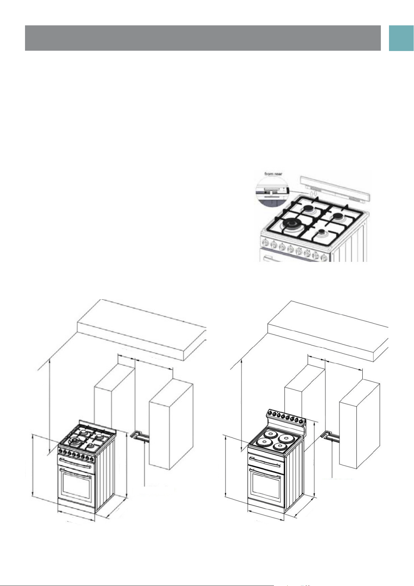
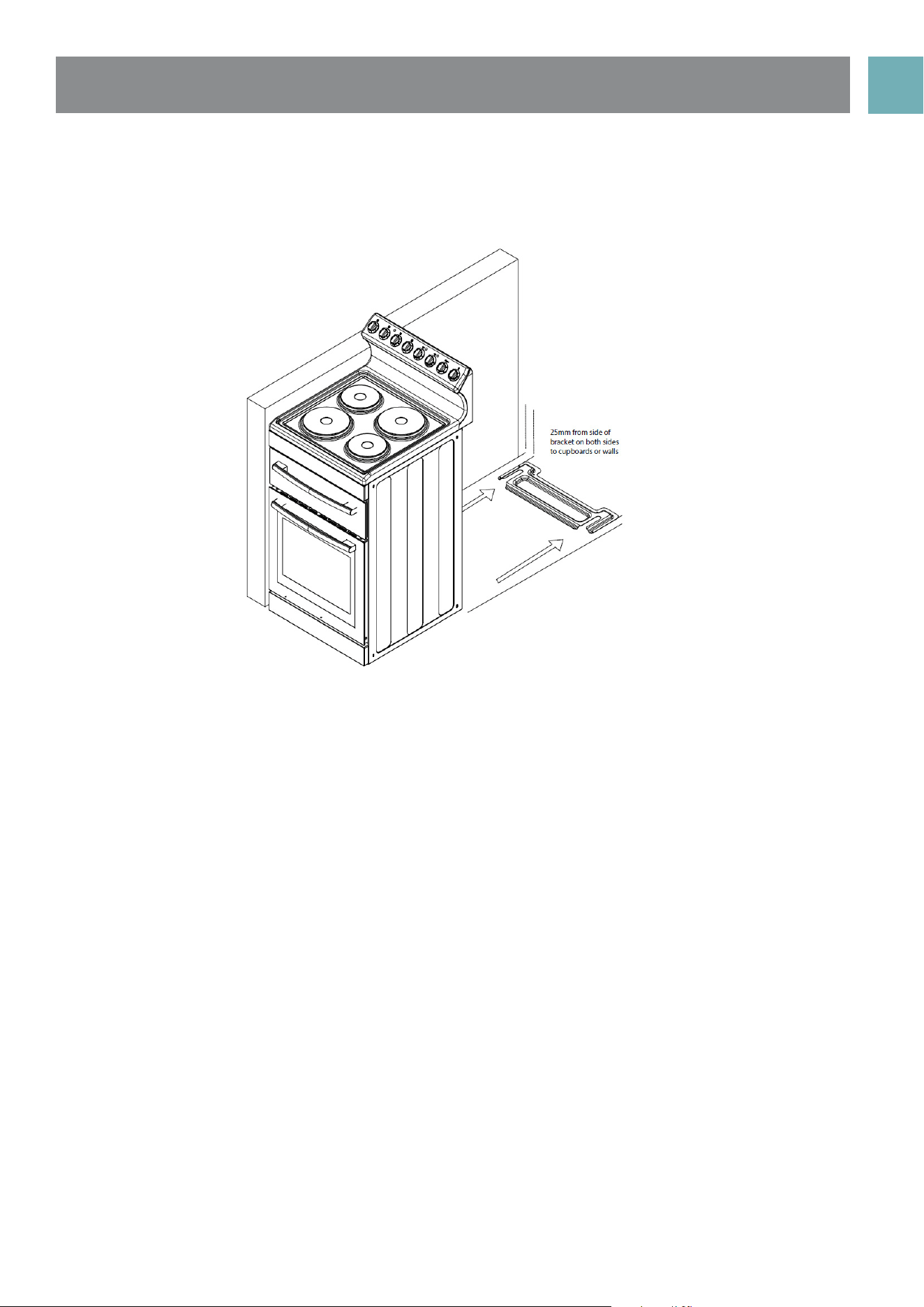
Locating the cooker
Study the diagrams below to be sure of the dimensions
required to locate the cooker safely. Make sure that
the top of the cooker is at least 10mm higher than the
level of the bench tops. Unscrew leveling legs by about
10mm to give clearance to the anti-tilt floor bracket.
The appliance has been designed to fit in a 550mm
wide gap in kitchen cabinets. The cooker may also be
installed at the end of a line of benches or with a free
space on either side.
NOTE: To ensure cooker stability, both the anti-tilt floor
bracket and anti-movement / stability bolt (this is fitted
to the cooker during and located behind the kick
panel) must be installed on all cookers (electric and
gas).
Front control models - gas
The installation of splash back
• To fit splash back, align the 2 tabs of the
splash back with the corresponding holes in
the hob and push downwards.
• Fit screws.
min 100m
min 550m
min 600m
910mm
950mm
630mm
Anti-tilt bracket
540mm
min 100m
min 550m
min 600m
910mm
1140mm
630mm
Anti-tilt bracket
540mm
Front control models Rear control models
USER MANUALPG 29
(Refer to diagram relating to minimum clearances required for correct installation)
• Determine position of cooker and ant-tilt plate.
• Securely fix the anti-tilt plate to the floor with appropriate fasteners.
• Slide the cooker into the anti-tilt plate to double check. And then slide out the cooker.
• Connect electricity supply but do not turn on until installation is completed.
• Slide the cooker back into the anti-tilt plate so that rear cover rests against the rear wall. Then check
the height and level of the cooker. If required, pull the cooker back out and adjust the leveling feet as
required.
USER MANUALPG 30
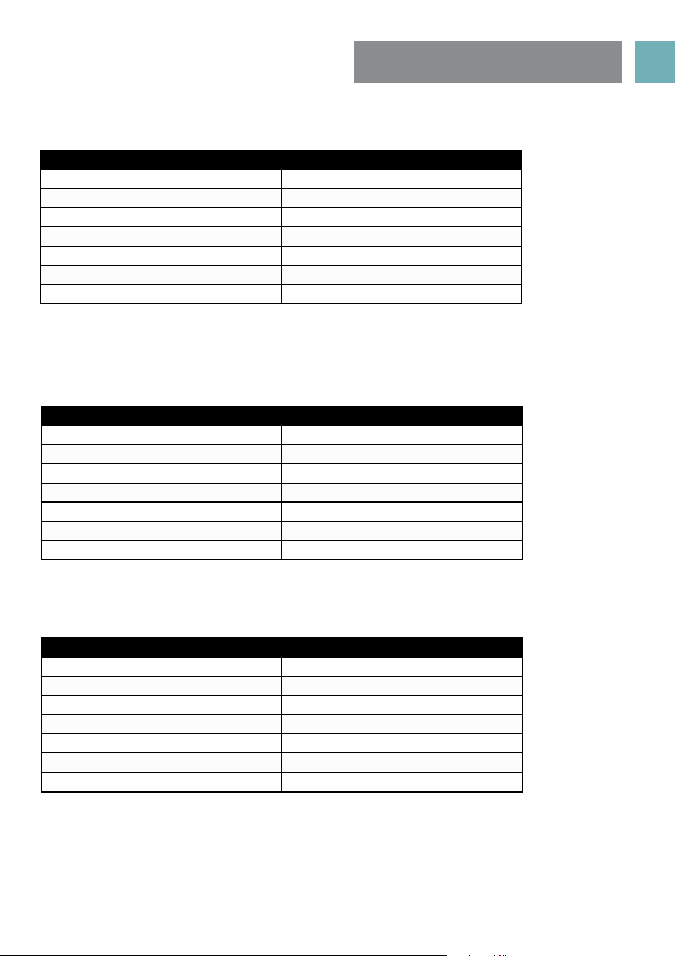
TECHNICAL
SPECIFICATIONS
Model EFS54RC-DCW / EFS54RC-DCB
oven capacity (L) 83
grill capacity (L) 20
coltage (v) 220-240
frequency (Hz) 50-60
power (W) 8450-10050
product dimension (mm) 540*630*1140
package size (mm) 636*740*1200
Model EFS54FC-DCW
oven capacity (L) 83
grill capacity (L) 20
coltage (v) 220-240
frequency (Hz) 50-60
power (W) 8450-10050
product dimension (mm) 540*630*910
package size (mm) 590*712*960
Model EFS54RC-DRW
oven capacity (L) 83
grill capacity (L) 20
coltage (v) 220-240
frequency (Hz) 50-60
power (W) 8490-10170
product dimension (mm) 540*630*1140
package size (mm) 636*740*1200
USER MANUALPG 31
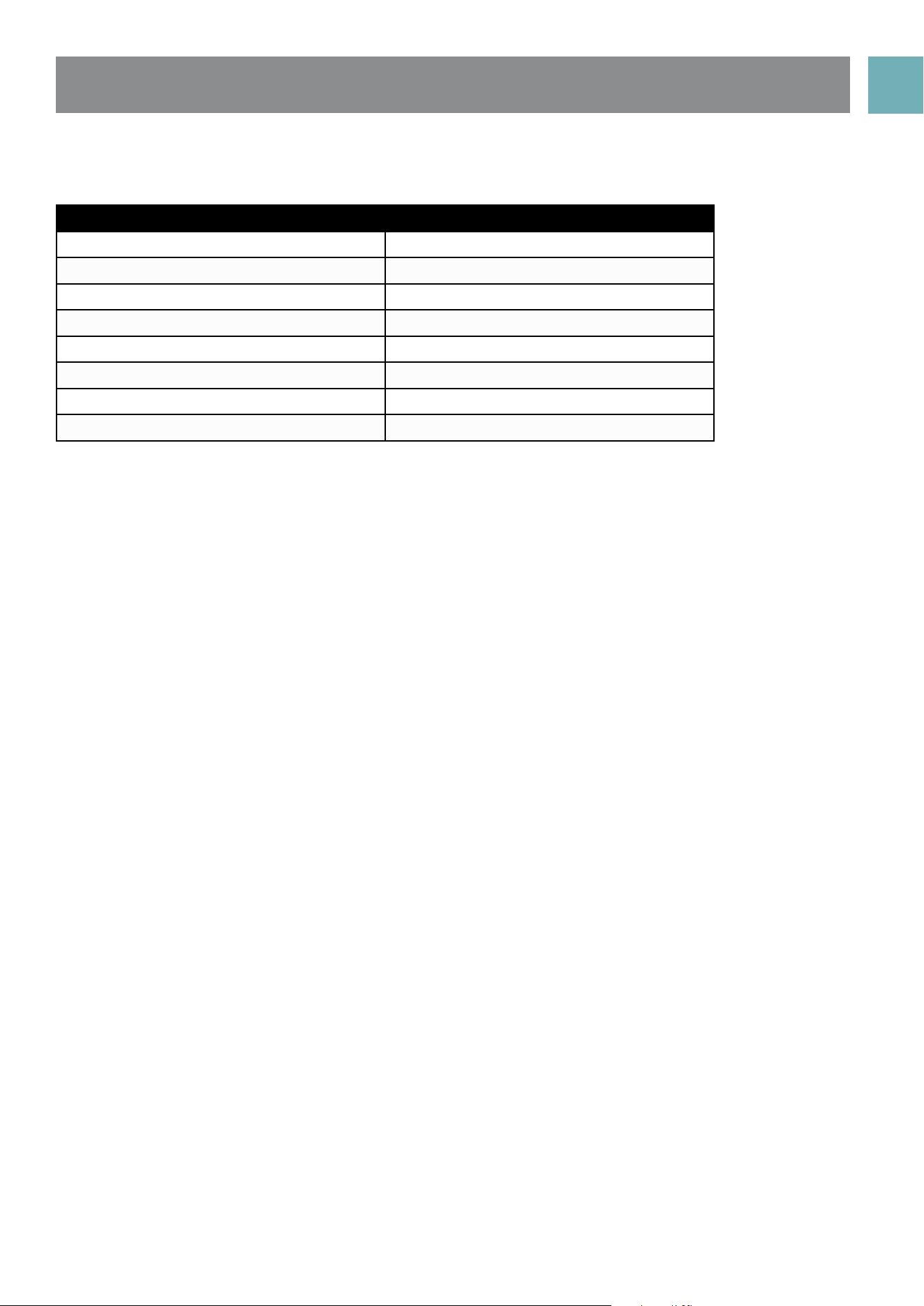
Model EFS54FC-DDS
oven capacity (L) 83
grill capacity (L) 20
coltage (v) 220-240
frequency (Hz) 50-60
power (W) 3490-4170
burner power (W) (NG/LPG 29.88 mj/h)
product dimension (mm) 540*630*910
package size (mm) 590*712*960

USER MANUALPG 32
This warranty is provided in Australia by Glen Dimplex Australia Pty Limited ABN 69 118 275 460 (Phone
number 1300 556 816) and in New Zealand by Glen Dimplex New Zealand Limited NZBN 9429000069823
(Phone number 09 274 8265) in respect of the Euromaid product.
1. Euromaid Express Warranty
Subject to the exclusions below, we warrant that the product will not have any electrical or mechanical
breakdowns within:
a) In the case of Euromaid products used for personal, domestic or household purposes, a period of 2 years
from the date the product is purchased as a brandnew product from a retailer located in Australia / New
Zealand.
b) In the case of Euromaid products used for purposes other than personal, domestic or household purposes
(including business or commercial use), a period of 90 days from the date the product is purchased as a
brand-new product from a retailer located in Australia / New Zealand. Euromaid products are designed
and intended for domestic use only; and
c) All warranty repairs must be carried out by Glen Dimplex or their nominated service agent
Note: warranty periods detailed above may vary in line with agreements with select retail and builder
partners and may differ between Australia and New Zealand. The benefits conferred by this express
warranty are in addition to the Consumer Guarantees referred to in section 3 and any other statutory rights
you may have under the Australian / New Zealand Consumer Law and/or other applicable laws.
2. Warranty exclusions
This express warranty does not apply where:
a) The product has been installed, used or operated otherwise than in accordance with the product
manual or other similar documentation provided to you with the product;
b) The product requires repairs due to damage resulting from accident, misuse, incorrect installation, insect
or vermin infestation, improper liquid spillage, cleaning or maintenance, unauthorised modification, use on
an incorrect voltage, powersurges and dips, voltage supply problems, tampering or unauthorised repairs by
any persons, use of defective or incompatible accessories or exposure to abnormally corrosive conditions,
events independent of human control which occurred after the goods left the control of Glen Dimplex;
c) The repair relates to the replacement of consumable parts such as fuses and bulbs or any other parts of
the product which require routine replacement;
d) You are unable to provide us with reasonable proof of purchase for the product;
e) the breakdown occurs after the expiry of the express warranty period set out in
section 1 or
f) the product was not purchased in Australia / New Zealand as a brand-new
product.
3. Consumer guarantees
Our goods come with guarantees that cannot be excluded under the Australian / New Zealand Consumer
Law. You are entitled to a replacement or refund for a major failure and for compensation for any other
reasonably foreseeable loss or damage. You are also entitled to have the goods repaired or replaced if the
goods fail to be of acceptable quality and the failure does not amount to a major failure.
MANUFACTURER
GUARANTEE

USER MANUALPG 33
MANUFACTURER
GUARANTEE
4. How to make a claim.
You may make a claim under this warranty through our website, contacting our customer care line or
via email. Contact details for Glen Dimplex Australia and New Zealand can be found at the end of this
document
To make a valid claim under this warranty, you must:
a) Lodge the claim with us as soon as possible and no later than 14 days after you first become aware of
the breakdown;
b) Provide us with the product serial number;
c) Provide us with reasonable proof of purchase for the product. This can take the form of a store receipt,
new home handover form or other payment receipt documentation; and
d) If required by us, provide us (or any person nominated by us) with access to the premises at which the
product is located at times nominated by us (so that we can inspect the product).
Washing
5. Warranty claims
If you make a valid claim under this warranty and none of the exclusions set out in
• section 2 apply, we will, at our election, either repair the product or replace the
product with a product of identical specification (or where the product is superseded
or no longer in stock, with a product of as close a specification as possible).
Goods presented for repair may be replaced by refurbished goods of the same type
rather than being repaired. Refurbished parts may be used to repair the goods.
Products are designed and supplied for normal domestic use. We will not be liable to
you under this warranty for business loss or damage of any kind whatsoever.
Glen Dimplex Australia Pty Ltd
www.glendimplex.com.au
Australia
Ph: 1300 556 816
customer[email protected]
Glen Dimplex New Zealand Ltd
www.glendimplex.co.nz
New Zealand
Ph: 09 274 8265

PG 34 VERSION 20210420
Glen Dimplex Australia Pty Ltd
www.glendimplex.com.au
For service advice, please contact the Customer Care Centre by phone or email below.
Australia
Ph: 1300 556 816
customer[email protected]
READ THE INSTRUCTION BOOKLET BEFORE INSTALLING AND USING THE
APPLIANCE.
The manufacturer will not be responsible for any damage to property or to persons caused by incorrect
installation or improper use of the appliance.
The manufacturer is not responsible for any inaccuracies, due to printing or transcription errors, contained in
this manual. In addition, the appearance of the figures reported is also purely indicative.
The manufacturer reserves the right to make changes to its products when considered necessary and
useful, without affecting the essential safety and operating characteristics. Glen Dimplex constantly seeks
ways to improve the specifications and designs of their products.
Whilst every effort is made to produce up to date literature, this document should not be regarded as an
infallible guide. Actual product only should be used to derive cut out sizes. All appliances must be installed
by a qualified person/s with adherence to the relevant electrical, plumbing and building codes, with
compliance being issued as required by state or national legislation.
Additionally, all upright cookers must have the anti-tilt device installed correctly in adherence to the
relevant standards by a licenced installer. For maximum effectiveness and efficiency all rangehoods should
be installed with the use of ductwork, by a licenced installer with adherence to the relevant state and
national building codes and regulations.
All Glen Dimplex appliances are for Domestic use only, and must be installed by a licence installer into
Domestic Applications only, without exception and to the required Authorities guidelines. Any installation
outside of this will VOID warranty. Alfresco areas are not a Domestic application.
Glen Dimplex New Zealand Ltd
www.glendimplex.co.nz
New Zealand
Ph: 09 274 8265