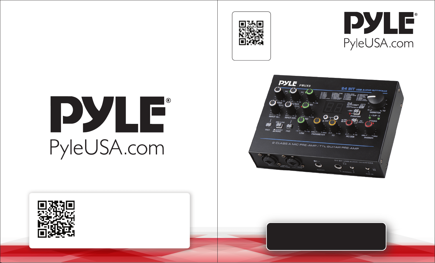
USER GUIDE
Professional USB Audio Interface
PMUX9
Questions or Comments?
We are here to help!
Phone: 1.718.535.1800
PyleUSA.com/ContactUs
Visit Our Website
SCAN ME
PyleUSA.com

READ ALL INSTRUCTIONS CAREFULLY BEFORE USING THIS PRODUCT.
RETAIN THIS OWNER’S MANUAL FOR FUTURE REFERENCE.
Features:
• Ultralow Noise Design with High Headroom
• USB Audio Interface for Computer Playing & Recording
• Preset 24 Digital Eects
• Provides 24-Bit/48kHz Resolution for Detailed and Pristine Recording Quality
• Independent 3.5mm Stereo Input
• Flexible Connectivity for Various External Devices
• Two Headphone Output Options (6.35mm & 3.5mm Stereo)
• Recording, Monitoring, and Leveling in Compact Spaces
• Rugged Metal Housing with a Compact Size
• DC 5V Power Supply or PC Power Supply
What's in the Box:
• USB Audio Interface
• USB Cable
Technical Specications:
• Power Consumption: 7W
• Power Output Current: 1A
• Power Output Voltage: DC 5V
• Phantom Power Voltage: +48V DC
• T.H.D.: <0.5% @ +4dBu (20Hz-20kHz)
• USB Interface: 2.0 Type-B
• Frequency Response: ±1dB, +4dBu @ 1kHz
• MIC/LINE: 2 Combo Jacks (XLR + 6.35mm jack)
• Product Dimensions (L x W x H): 1.5'' x 6.8'' x 4.7''
FCC INFORMATION
WARNING: Changes or modications not expressly approved by the party responsible for
compliance could void the user’s authority to operate the equipment.
NOTE: This equipment has been tested and found to comply with the limits for a Class B
digital device, pursuant to Part 15 of the FCC Rules. These limits are designed to provide
reasonable protection against harmful interference in a residential installation.
This unit generates, uses, and can radiate radio frequency energy, and if not installed and
used in accordance with the instructions, may cause harmful interference to radio
communications. However, there is no guarantee that interference will not occur in a
particular installation. If this equipment does cause harmful interference to radio or
television reception, which can be determined by turning the equipment o and on, the
user is encouraged to try and correct the interference by one or more of the following
measures:
• Reorient or relocate the receiving antenna.
• Increase the separation between the equipment and receiver.
• Connect the equipment to an outlet on a circuit different from that to which the receiver
is connected.
• Consult the dealer or an experienced radio/TV technician for help.
This device complies with Part 15 of the FCC Rules.
Operation is subject to the following two conditions:
1. This device may not cause harmful interference.
2. This device must accept any interference received, including interference that may cause
undesired operation.
ww w.PyleUSA.com
2
ww w.PyleUSA.com
3
California Prop 65 Warning
WARNING:
This product may expose you to chemicals, which is known to
the state of California to cause cancer, birth defects and other
reproductive harm. Do not ingest.
For more info go to: www.P65warnings.ca.gov
Attention:
To avoid possible malfunction, damage to the product, data loss, or harm to
other property, please follow these guidelines:
OPERATION
• Do not use the device near TVs, radios, stereo equipment, mobile phones, or
other electronic devices to prevent noise interference.
• Avoid exposing the device to excessive dust, vibrations, extreme cold, heat, or
direct sunlight.
• Do not place vinyl, plastic, or rubber objects on the device, as they may discolor
the panel.
• Clean the device with a dry, soft cloth. Avoid using paint thinners, solvents, or
chemical-impregnated cloths.
• Allow the device to acclimate if condensation occurs due to temperature changes.
Wait several hours before turning it on.
• Avoid setting all controls to their maximum levels, as this may cause feedback
and damage connected speakers.
• When powering on your audio system, always turn on the power amplier last to
avoid speaker damage. Power o the amplier rst when turning o the system.
Precautions for USB 2.0 and 5V DC Terminals:
• Use an AB-type USB cable (USB 3.0 cables are not supported).
• Disable any power-saving modes (e.g., suspend, sleep, or standby) on your
computer before connecting to the USB 2.0 terminal.
• If the computer or device crashes, restart the software or operating system, or
disconnect and reconnect the unit.
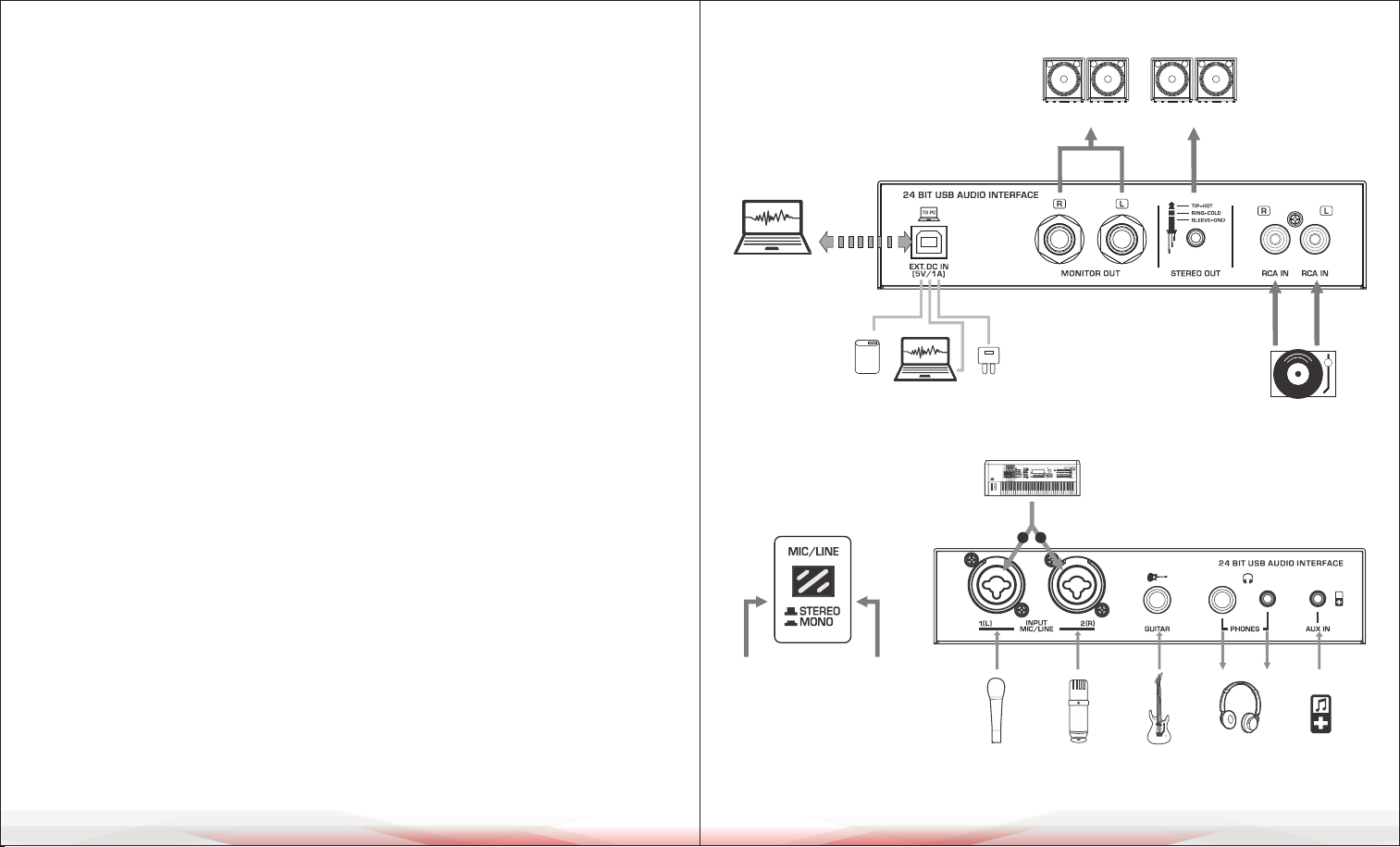
CONNECTION DIAGRAM
For MIC & LINE inputs
ww w.PyleUSA.com
4
ww w.PyleUSA.com
5
*Keep the buttons bounce
up, for STEREO inputs.
*Press down the buttons,
for MONO inputs.
Syntesizer
Dynamic
Microphone
Condenser
Microphone
Guitar
Headphones
External Audio
L
R
Stereo
Transfer
and
Record
Power Supply:DC 5V,1A
Power Socket
Power Bank
PC USB Power Supply
Speakers
CD Player
Speakers
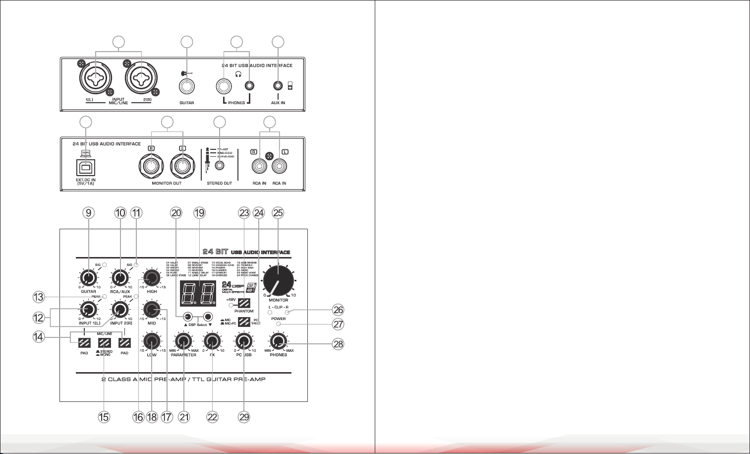
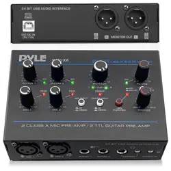
CONTROLS AND FUNCTIONS CONTROLS AND FUNCTIONS
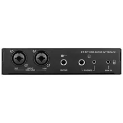
1. [MIC/LINE] Input jack: Connect a microphone or musical instrument.
Supports both XLR and unbalanced 1/4" plugs.
2. [GUITAR] Input jack: Connect an instrument such as an electric guitar or bass.
3. [AUX IN] 3.5mm auxiliary input jack: Provides exible connectivity for various
external devices. AUX IN volume is controlled by external devices or the
MONITOR knob. The input signal from AUX IN can be recorded to a PC only when
the [PC REC] switch is in the up position during MIC+PC recording.
Recording volume is controlled externally without MONITOR knob control.
4. [RCA IN] Stereo input jack: Connect a TAPE or CD player.
5. [PHONES] Output jack: Two headphone jack options (6.35mm and 3.5mm) for
stereo phones.
6. [STEREO OUT] 3.5mm auxiliary output jack.
7. [MONITOR OUT] Output jack: Connect to an active speaker or amplier.
8. [USB 2.0] Terminal: For data transfer, recording, and power supply.
When connected to a computer, it powers the mixer, and audio data is exchanged
between the mixer and computer. Supports stereo playback and recording with
a 24-Bit/48kHz sampling rate. If using a power socket or power bank, ensure the
output voltage is 4.8V to 5.2V and the output current is at least 1A.
9. [GUITAR] Controller: Controls the input level of the guitar channel, adjusting to
balance the volume.
10. [RCA/AUX] Controller: Controls the input level of RCA and AUX inputs,
adjusting to balance the volume.
11. [SIG] Signal Indicator: Brightness changes with signal input intensity.
12. [INPUT 1-2 L-R] Controller: Controls the input level of MIC/LINE channels,
adjusting to balance the volume.
13. [PEAK] LED: Lights up when the input signal is too high. If it ashes consistently,
rotate the [INPUT] Controller counterclockwise to lower the volume.
14. [PAD] Button: Attenuates the sound input. Turn this on if you hear distortion
or if the [PEAK] LED indicator lights up.
ww w.PyleUSA.com
6
ww w.PyleUSA.com
7
1 2 5 3
8 7 6 4
15. [MIC/LINE] Converting Switch:
a. In the up position, it supports stereo input: MIC/LINE inputs 1(L) and 2(R)
form a stereo signal.
b. In the down position, it supports mono input: Two individual mono input
signals.
16. [HIGH] Treble Tone Controller: Adjusts to enhance or attenuate by 15dB
at 12kHz.
17. [MID] Mid Tone Controller: Adjusts to enhance or attenuate by 15dB at 2.5kHz.
18. [LOW] Bass Tone Controller: Adjusts to enhance or attenuate by 15dB at 80Hz.
19. Eector Display: Shows the selected eect number.
20. DSP Selecting Buttons: Press UP or DOWN to select one of 24 DSP eects
(refer to the eect list on page 7). The display ashes the selected eect number.
21. [PARAMETER] Controller: Adjusts eect depth, speed, etc.
22. [FX] Controller: Controls the eect level.
23. [+48V PHANTOM POWER] Button/LED: Turns on phantom power (+48V DC)
for XLR plug MIC mono inputs. Use this for condenser microphones requiring
phantom power.
24. [PC REC] Switch for PC Recording:
A. Use together with Point 15 [MIC/LINE] input switch.
B. When the [PC REC] switch is up during MIC+PC recording:
• Audio from the PC is recorded back to the PC, along with MIC, GUITAR, and
STEREO inputs.
• Recording volume for MIC and GUITAR is controlled by their channel knobs;
STEREO IN volume is controlled externally without MONITOR knob control.
• In mono mode, MIC/LINE inputs assign L and R recording tracks simultaneously.
In stereo mode, L and R inputs are assigned separately.
C. When the [PC REC] switch is down:
• Audio on the PC still plays, but it does not ow back to PC recording.
Only MIC and GUITAR inputs are recorded.
• Recording volume is controlled by channel knobs. MIC/LINE inputs assign L
and R recording tracks separately regardless of switch position.
25. [MONITOR] Controller: Adjusts the volume of the MONITOR output.
26. [CLIP L & R] LED: Lights up when the MONITOR output signal is too high.
27. [POWER ON] LED: Lights up when the mixer's power is on.
28. [PHONES] Controller: Controls the headphone volume.
29. [PC USB] Controller: Controls the input level from the PC USB port, adjusting
to balance the volume.
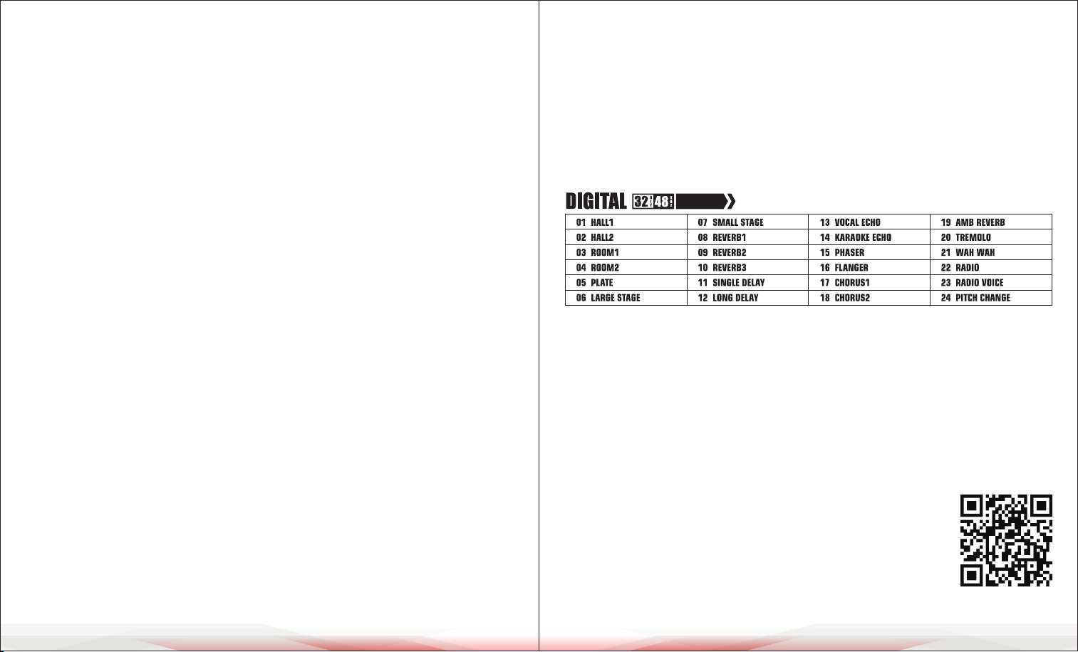
LIST OF EFFECTS
CLEANING, MAINTENANCE, AND STORAGE
• Cleaning: Wipe the device with a soft, dry cloth.
Avoid using liquids or abrasive cleaners.
• Maintenance: Check connections and cables regularly.
Replace any damaged parts immediately.
• Storage: Store in a cool, dry place away from sunlight and extreme temperatures.
Use the original packaging to protect the device.
ww w.PyleUSA.com
8
ww w.PyleUSA.com
9
REGISTER PRODUCT
Thank you for choosing PyleUSA. By registering your product,
you ensure that you receive the full benets of our exclusive
warranty and personalized customer support.
Complete the form to access expert support and to keep your
PyleUSA purchase in perfect condition.
Start Here
PyleUSA.com/pages/register
24 DSP