
P
PNEUMATIC TOOLS
403606-25
08/2
3
P
Operating and Maintenance Manual
P
P
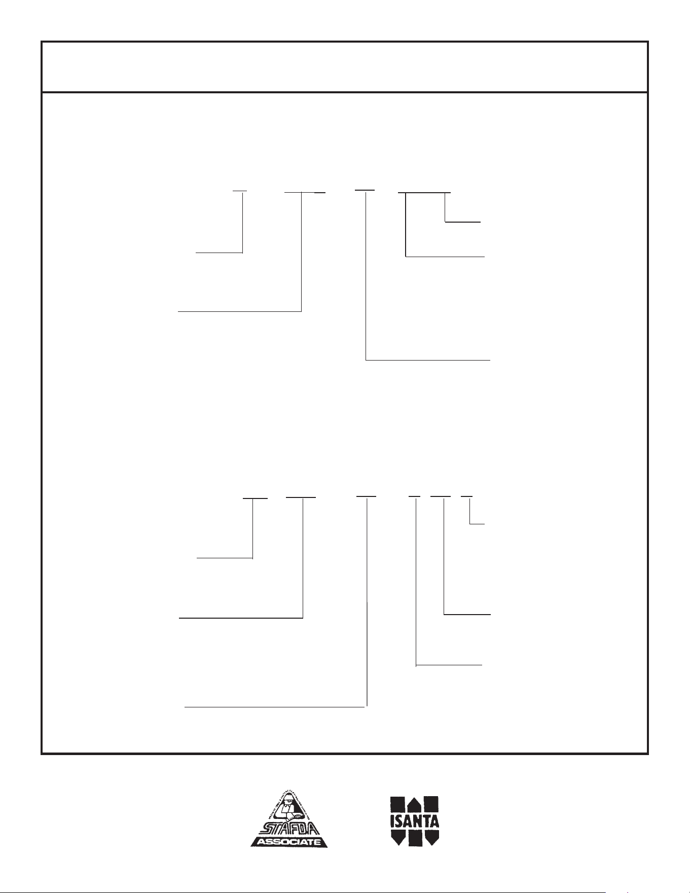
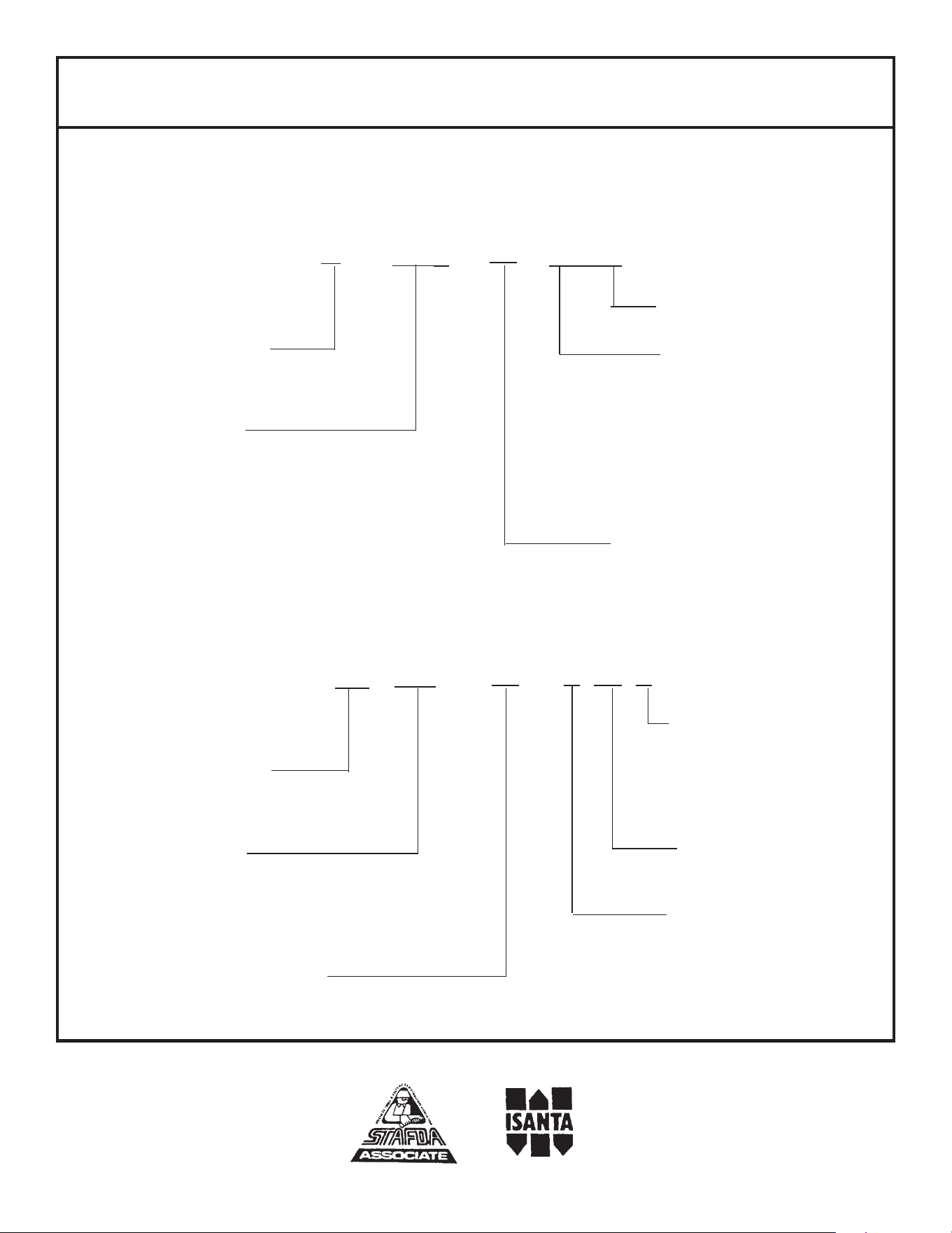
PASLODE MODEL NUMBER DESIGNATION
The model number of each Paslode tool contains information about the tool and the fasteners
that are used with it. The following example illustrates the information contained in this tool
model number.
STAPLER
Tool application letter
Maximum fastener
length, in inches that
can be used with the
tool
00 -
S 00 P
Type of tool
( P= powerpack)
( DL= double length)
Gauge of fastener
Indicates crown size
( W = wide)
( S = standard)
( I = intermediate)
( N = narrow)
Maximum fastener
length in millimeters
O
000
/
Paslode is a member of:
NAILER
Tool application letter
Maximum fastener
length, in inches that
can be used with the
tool
/
O
000
Type of tool
( C = coil nailer)
( S = strip nailer)
( F = finish nailer)
( R = Roof nailer)
Power Pack
C P
00
Maximum fastener
length in millimeters

INTRODUCTION
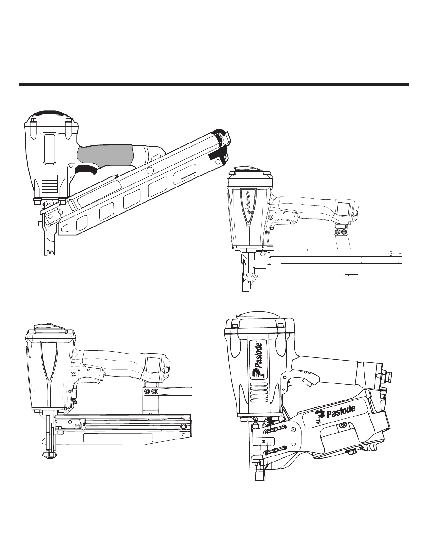
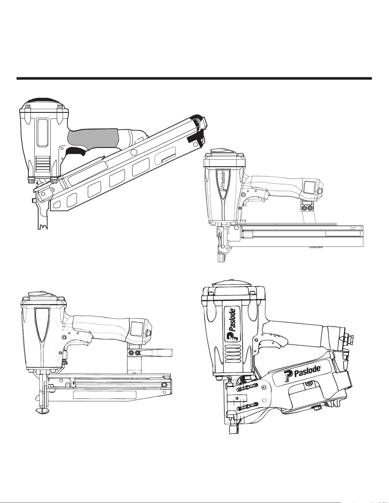
Congratulations on purchasing a Paslode pnuematic tool. You have made a wise choice.
A Paslode tool is a professional quality tool that combines power and speed in a light weight design for
versatile operation in a variety of industrial and construction applications.
.loot eht htiw emac taht noitatnemucod rehto lla dna launam eritne siht weiver ot emit eht ekat esaelP
They will help you to become familiar with operating a power fastening tool. Be sure to read the safety
instructions carefully before using your new tool. Also read Paslode's warranty statement in the back
of this manual.
Even though Paslode is a leader in the power fastening business, we continually strive to find new and
:tessa tnatropmi tsom ruo ot edam ev'ew tnemtimmoc a si tahT .stcudorp ruo gnivorpmi fo syaw retteb
our customer.
Paslode also manufactures a line of cordless tools featuring Impulse Technology, which are not covered
in this manual. For maintenance and safety information on the line of cordless tools, consult the
operating manuals for those tools.
TABLE OF CONTENTS
INTRODUCTION............................................................................................................... 1
SAFETY INSTRUCTIONS................................................................................................ 2
AIR SYSTEMS..................................................................................................................
3
TOOL INSTALLATION...................................................................................................... 5
TOOL OPERATION.......................................................................................................... 5
TOOL LOADING............................................................................................................... 6
MAINTENANCE................................................................................................................ 9
OPERATOR TROUBLESHOOTING................................................................................12
TOOL WARRANTY.................................................................................Inside Back Cover
1
WARNING
Failure to follow any of the above instructions could result in severe personal
injury to tool user and bystanders or cause damage to tool and property.
Contact your local Paslode Representative for presentation of Paslodeʼs Safety Awareness Program
SAFETY INSTRUCTIONS
SAFETY FIRST
These safety instructions provide information necessary
for safe operation of Paslode
®
tools. DO NOT ATTEMPT
TO OPERATE THE TOOL UNTIL YOU READ AND
UNDERSTAND ALL SAFETY PRECA
UTIONS AND
MANUAL INSTRUCTIONS.
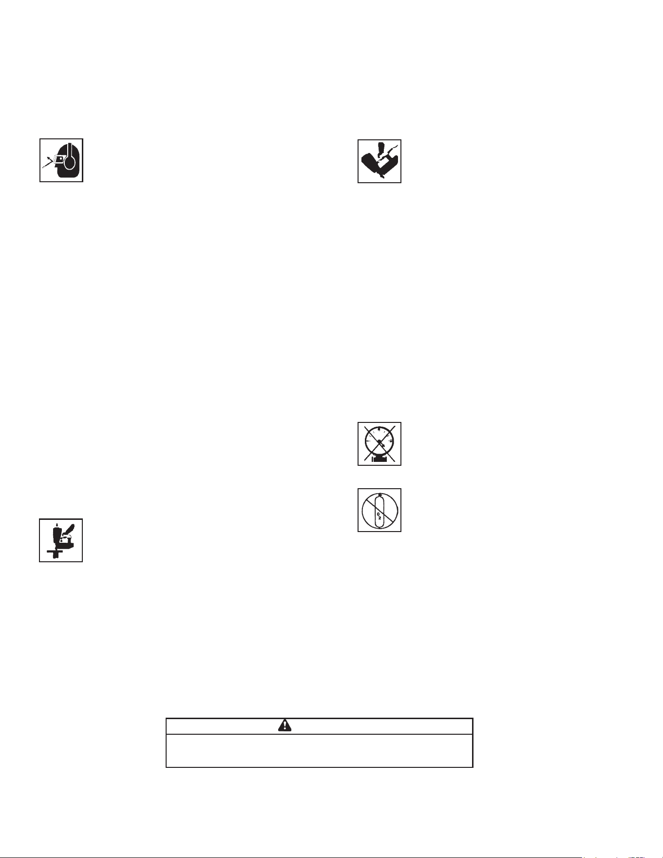
WEAR EYE AND HEARING PROTECTION
Always wear hearing and eye protection devices, that
conform to ANSI Z87+ requirements, when operating
or working in the vicinity of a tool. As an employer you
are responsible for enforcing the use of eye protection.
Wear hard hats in environments that require their use.
THE TOOL MUST BE USED ONLY FOR THE PUR
-
POSE FOR WHICH IT WAS DESIGNED
Do not throw the tool on the floor, strike the housing
in any way or use the tool as a hammer to knock
material into place.
NEVER ENGAGE IN HORSEPLAY WITH THE TOOL
The tool is not a toy so do not use it like one. Never
engage in horseplay with the tool or point it at yourself
or any other person, even if you think it is not loaded.
NEVER ASSUME THE TOOL IS EMPTY
Check the magazine for fasteners that may be left in the
tool. Even if you think the tool is empty or disconnected,
never point it at anyone or yourself. Unseen fasteners
could fire from the tool.
NEVER CLAMP THE TRIGGER IN A LOCKED OR
OPERATING POSITION
The trigger of the tool must never be tampered with,
disabled or clamped in a locked or operating position
since this will cause the tool to drive a fastener any
time the work contacting element depressed.
DO NOT LOAD FASTENERS WITH THE AIR LINE
CONNECTED, OR WITH THE TOOL TRIGGER OR
WORK CONTACTING ELEMENT DEPRESSED
When loading fasteners into the tool be sure you dis-
connect the air line and that you do not depress the
trigger or work contacting element.
OPERATE THE TOOL ONLY ON A WORKPIECE
The tool should be operated only when it is in contact
with the workpiece. Even then you should be careful
when fastening thin material or working near the edges
and corners of the workpiece since the fasteners may
drive through or away from the workpiece.
DO NOT DISABLE OR REMOVE THE WORK CON-
TACTING ELEMENT
This tool is equipped with a safety mechanism, called
a work contacting element, to help prevent accidental
firing. Never tamper with, disable or remove the work
contacting element. Do not use the tool unless the
work contacting element is working properly. The tool
could fire unexpectedly.
DISCONNECT THE TOOL WHEN NOT IN USE
Always disconnect the tool from the air line when it
is not in use, when you leave the work area or when
moving the tool to a new location. The tool must
never be left unattended because people who are
not familiar with the tool might handle it and injure
themselves or others.
CARRY THE TOOL ONLY BY THE HANDLE
Always carry the tool by the handle only. Never carry
the tool by the air hose or with the trigger depressed
since you could drive a fastener unintentionally and
injure yourself or someone else.
DO NOT WEAKEN THE TOOL HOUSING
The tool housing is a pressure vessel and should never
be weakened by having your companyʼs name, area of
work or anything else stamped or engraved into its
surface.
DISCONNECT THE TOOL WHEN PERFORMING
REPAIRS AND CLEARING JAMS
Never attempt to clear a jam or repair a tool unless you
have disconnected the tool from the air line and
removed all remaining fasteners from the tool.
ALWAYS USE THE PROPER FITTING FOR THE
TOOL
Only MALE pneumatic type air connectors should be
fitted to the tool, so that high pressure air in the tool is
vented to atmosphere as soon as the air line is dis-
connected.
NEVER install FEMALE quick disconnect couplings on
the tool. Female couplings will trap high pressure air in
the tool when the air line is disconnected, leaving the
tool charged and able to drive at least one fastener.
DO NOT EXCEED THE MAXIMUM RECOMMENDED
AIR PRESSURE
.
erusserp ria dednemmocer eht ta ylno loot eht etarepO
Do not exceed the maximum air pressure marked on
the tool. Be sure the air pressure gauge is operating
properly and check it at least twice a day.
Never use any bottled air or gases such as oxygen to
operate the tool since they could cause the tool
to
explode. Do not operate in explosive atmospheres.
INSPECT TOOL FOR PROPER OPERATION
.deriuqer sa etacirbul dna yliad tsael ta loot eht naelC
Never operate a dirty or malfunctioning tool.
USE ONLY PASLODE RECOMMENDED PARTS AND
FASTENERS
Use only parts and fasteners specifically designed and
recommended by Paslode for use in the tool and for
work to be done. Using unauthorized parts and
fasteners or modifying the tool in any way creates
dangerous situations. Replace all missing warning
labels---refer to tool schematic for correct placement
and part number.
2
3
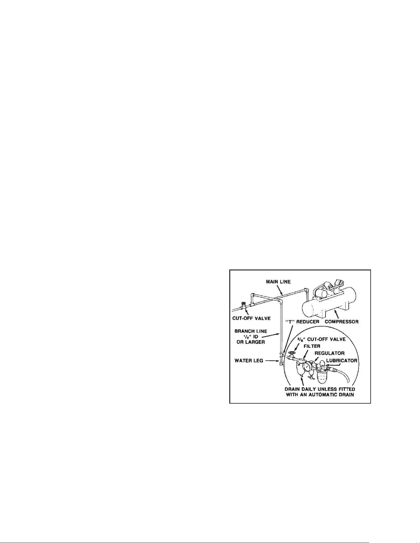
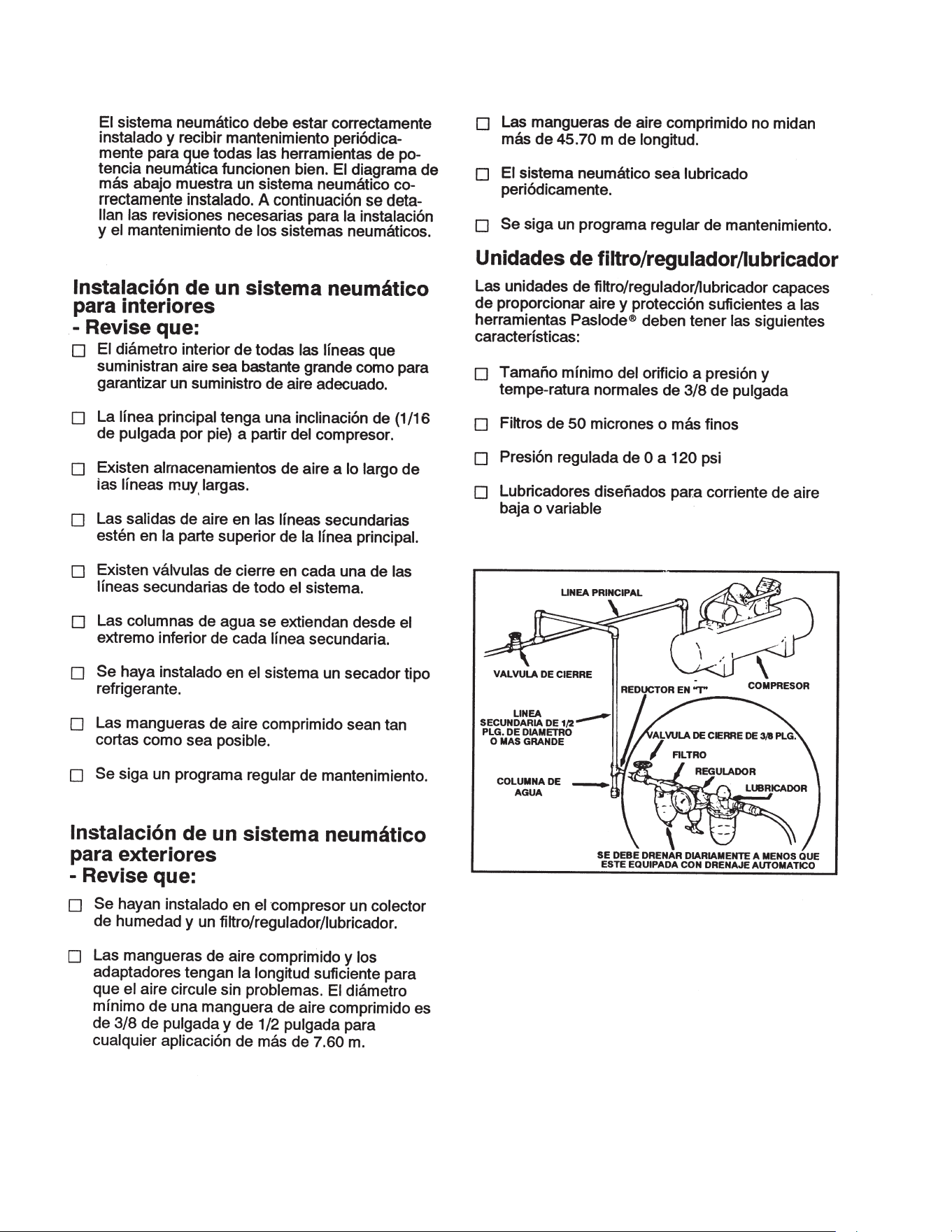
AIR SYSTEMS
For air-powered tools to work their best, the air
supply system must be properly installed and
maintained regularly. A drawing in this section
shows a properly installed air supply system.
Handy checklists for installing and maintaining
air supply systems follow.
Indoor Air System Installation
-Be certain that:
•
All pipes supplying air have a large enough
inside diameter to ensure adequate air supply.
•
The main supply pipe slopes down, away from
the compressor (1/16 inch per foot).
•
Air storage is provided along lengthy air lines.
•
Pipe line branch outlets are at the top of the
main pipe line.
•
Cutoff valves are provided at each branch pipe
line throughout the system.
•
Water legs extend from the bottom of each
branch line.
•
A refrigerant-type dryer is installed on the
system.
• Air hoses are kept as short as practical.
•
A regular maintenance program is followed.
Outdoor Air System Installation
-Be certain that:
•
A moisture trap and a filter/regulator/lubricator
are installed at the compressor.
•
Air hoses and fittings are large enough so that
air flow is not restricted. Minimum hose size
is 3/8 inch ID with 1/2 inch ID hose used for
any application over 25 feet.
• Air hoses are not longer than 150 feet.
• The air system is lubricated regularly.
•
A regular maintenance program is followed.
Filter/Regulator/Lubricator Units
Filter/regulator/lubricator units that can supply
enough air and protection for Paslode tools
must meet the following specifications:
• Minimum 3/8 inch NPT port size .
• 50 micron or fine filters.
•
Regulated pressure from zero to 120 psi.
•
Lubricators designed for low or changing
airflow.
3
AIR SYSTEMS
For air-powered tools to work their best, the air
supply system must be properly installed and
maintained regularly. A drawing in this section
shows a properly installed air supply system.
Handy checklists for installing and maintaining
air supply systems follow.
Indoor Air System Installation
-Be certain that:
•
All pipes supplying air have a large enough
inside diameter to ensure adequate air supply.
•
The main supply pipe slopes down, away from
the compressor (1/16 inch per foot).
•
Air storage is provided along lengthy air lines.
•
Pipe line branch outlets are at the top of the
main pipe line.
•
Cutoff valves are provided at each branch pipe
line throughout the system.
•
Water legs extend from the bottom of each
branch line.
•
A refrigerant-type dryer is installed on the
system.
• Air hoses are kept as short as practical.
•
A regular maintenance program is followed.
Outdoor Air System Installation
-Be certain that:
•
A moisture trap and a filter/regulator/lubricator
are installed at the compressor.
•
Air hoses and fittings are large enough so that
air flow is not restricted. Minimum hose size
is 3/8 inch ID with 1/2 inch ID hose used for
any application over 25 feet.
• Air hoses are not longer than 150 feet.
• The air system is lubricated regularly.
•
A regular maintenance program is followed.
Filter/Regulator/Lubricator Units
Filter/regulator/lubricator units that can supply
enough air and protection for Paslode tools
must meet the following specifications:
• Minimum 3/8 inch NPT port size .
• 50 micron or fine filters.
•
Regulated pressure from zero to 120 psi.
•
Lubricators designed for low or changing
airflow.
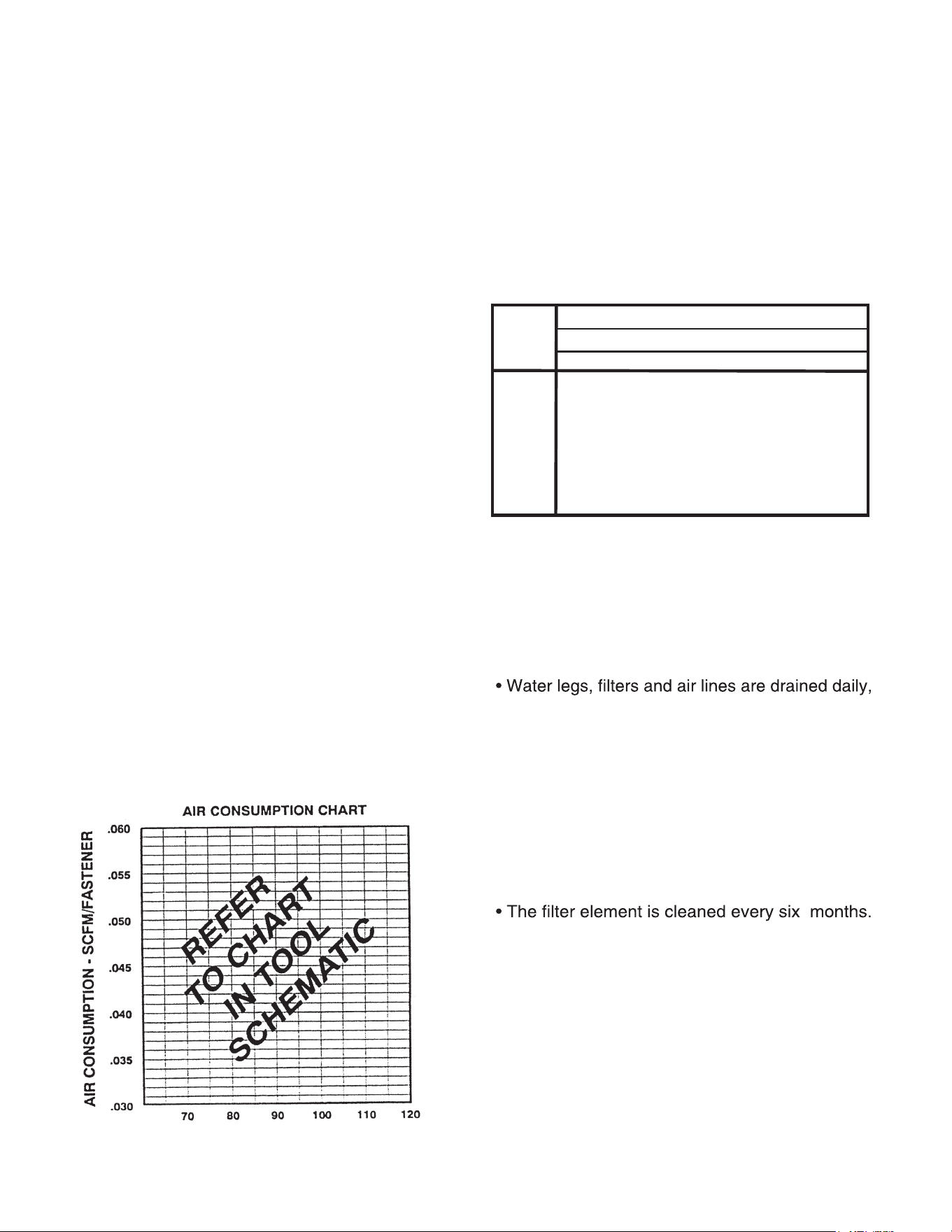
AIR SYSTEMS - Continued
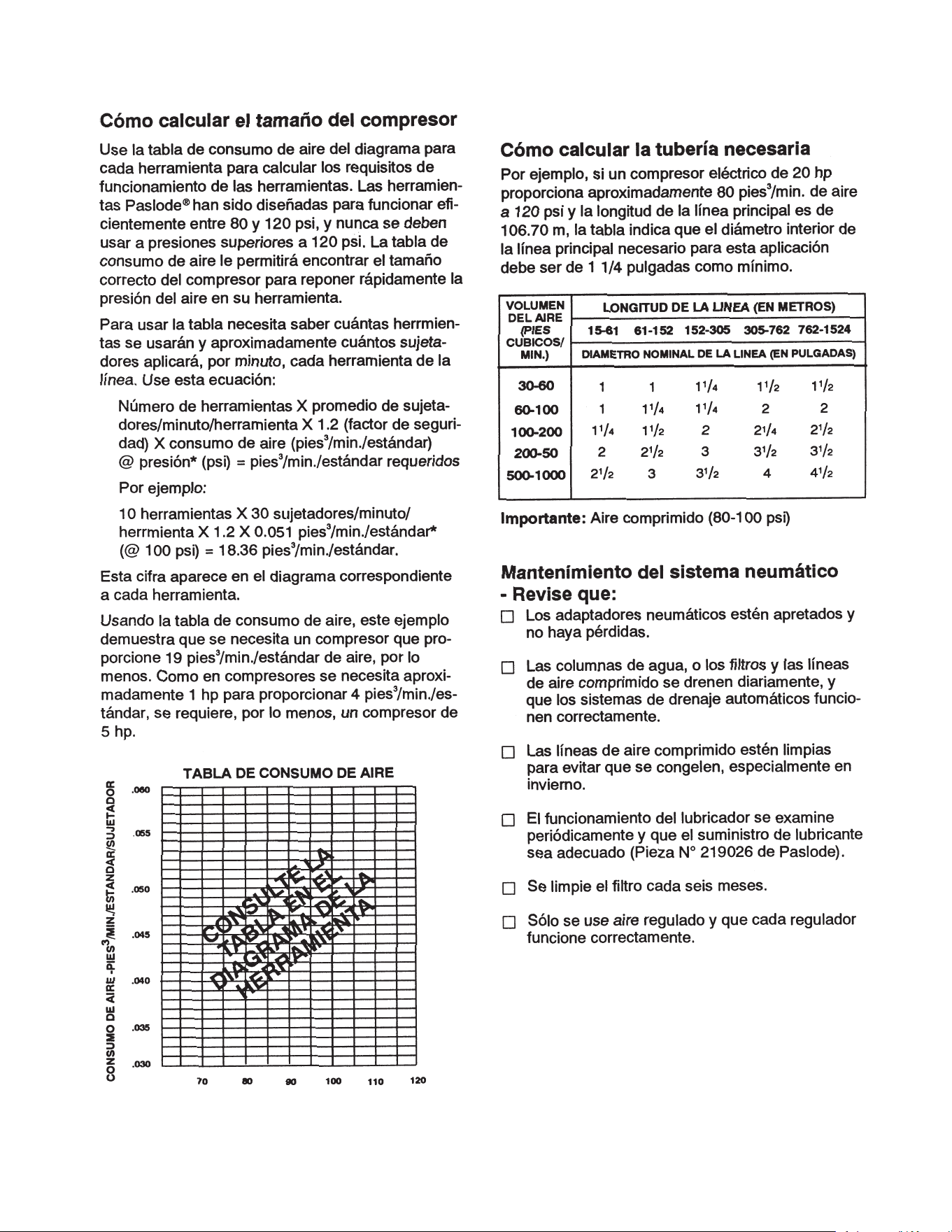
Calculating Compressor Size
Use the air consumption chart in the Tool
Schematic for each tool when calculating the
operating requirements for the tools.
Paslode
tools are designed to operate efficiently
between 80 and 120 psi and should never be
operated at pressure greater than 120 psi.
The air consumption chart will help you find
the correct compressor size for your application
that will quickly replenish tool air pressure.
To use the chart you will need to know how
many tools will be used and approximately
how many fasteners will be driven each minute
by each tool on the line. Using the equation:
Number of tools X average fasteners/minute/
tool X 1.2 (safety factor) X air consumption
(scfm) @ pressure* (psi) = scfm required.
We can use the following example:
10 tools X 30 fasteners/minute/tool X 1.2 X
0.051scfm* (@100psi) = 18.36 scfm.
*This number is found in the Air Consumption
Chart
In this example, using the air consumption
chart we find that a compressor providing at
least 19 scfm of air is required. Because in
compressors approximately 1 hp is required
to produce 4 scfm, a compressor of at least
5 hp is required.
Calculated Required Piping
For example, given a 20 hp electric compressor
supplying approximately 80 cfm of air at 120 psi
and a main supply pipe length of 350 feet, we
see by the table the minimum main pipe inside
diameter required for this applica
t
ion is 1-1/4
Pneumatic System Maintenance
- Be certain that:
•
Pneumatic fittings are tight and do not leak.
and ensure that automatic draining systems
are operating correctly.
• Air lines are cleared to prevent freezing,
especially in winter.
• Lubricator operation is checked regularly
and ensure it has an adequate supply of
lubricant (Paslode Part No. 403720).
• Only regulated air is being used and that
each regulator is operating properly.
4
VOLUME
OF AIR
(CFM)
LENGTH OF RUN (FT.)
NOMINAL PIPE DIAMETER (IN.)
50-200 290-500 500-1000 1000-2500 2500-5000
30-60
60-100
100-200
200-500
500-1000
1 1 1¼ 1½ 1½
1 1¼ 1¼ 2 2
1¼ 1½ 2 2¼ 2½
2 2½ 3 3½ 3½
2½ 3 3½ 4 4½
inch.
TOOL INSTALLATION
Your Paslode tool comes ready for immediate
use and can be installed by following these steps:
1. SAFETY - All tool operators and their immediate
supervisors must become familiar with the operator
safety instructions before operating the tool. The
instructions are on page 2 of this manual.
2. Included with each tool are one copy of this
Safety and Maintenance manual and one copy of
the Tool Schematic. Keep these publications for
future reference. An ownership registration card
is also included. This card must be completed
and returned to Paslode immediately to register
your ownership.
4. Install a filter/regulator/lubricator unit, with a
gauge as close as practical to the tool, preferably
within ten feet. Refer to the Air Systems section of
this manual for air hose requirements and lengths.
In general, no other special installation is required.
5. If the operator is working at a bench or table,
it is usually best to run the air line underneath the
bench. A small tray under the benchtop can hold
the fastener supply and the tool when not in use.
6. If this tool does not work when it is first con-
nected, do not try to make repairs. Call your
Paslode representative immediately.
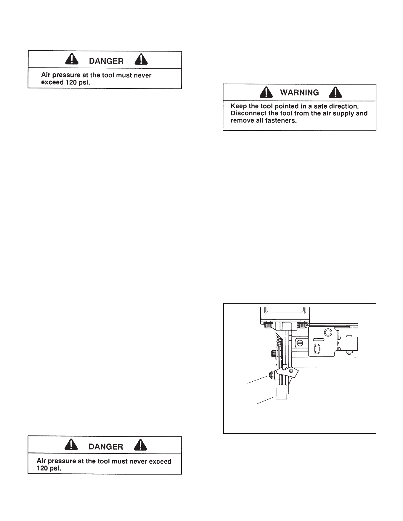
TOOL OPERATION
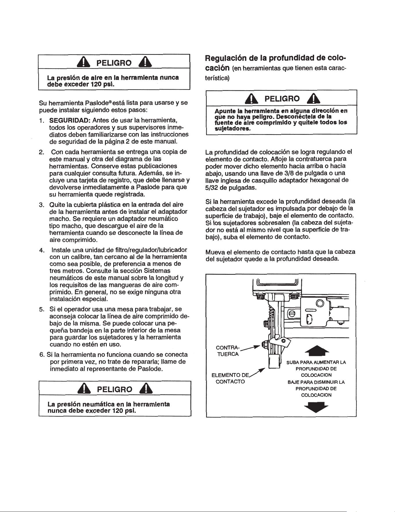
Depth of Drive Adjustment
(On tools equipped with this feature)
The depth of drive adjustment is made by
adjusting the work contacting element. The
lock nut is loosened to allow the element to be
moved up or down. You will need a 3/8 inch
open end or 5/32 inch hex socket wrench to
make this adjustment.
If the tool is overdriving (the fastener head or
crown is driven below the work surface), the
work contacting element should be moved
downward. If the fasteners stand up (the head
or crown is not flush with the surface), the work
contacting element should be moved up.
Adjust the work contacting element until the
fastener head or crown depth meets job re-
quirements.
LOCK
NUT
WORK
CONTACTING
ELEMENT
MOVE UP
TO INCREASE
DRIVE DEPTH
MOVE DOWN
TO DECREASE
DRIVE DEPTH
➔
➔
5
®
3. The plastic cap in the air inlet of the tool
line is disconnected.
installed. Tools are threaded for either a
must be removed before the male fitting is
3/8” NPT or 1/4” NTP air fitting. The fitting
must be a male pneumatic type that dis-
charges the air from the tool when the air
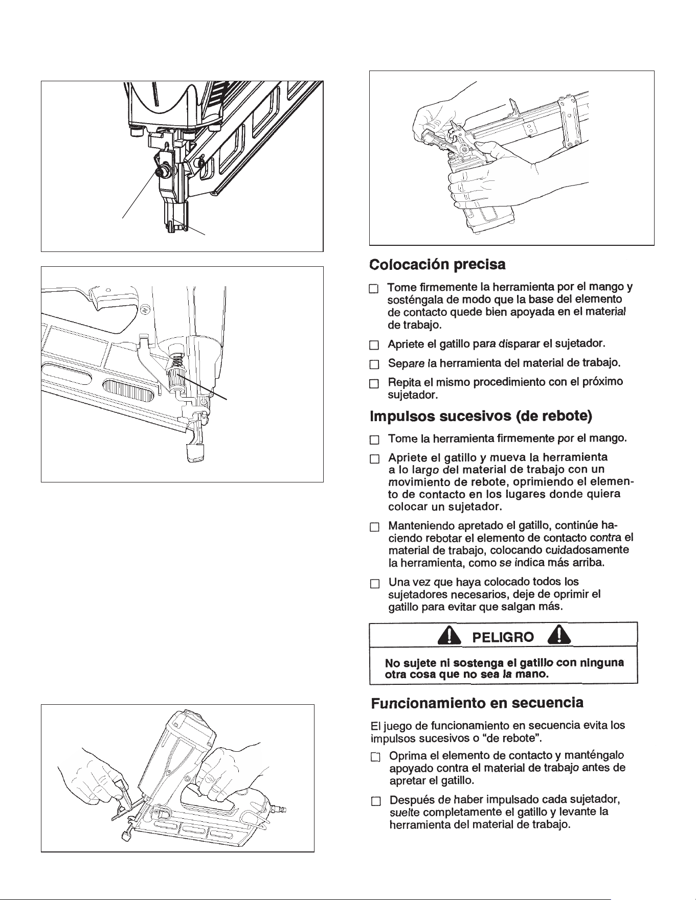
Precision Placement Driving - (Orange Trigger)
■ Grasp the tool handle firmly and hold the bottom of
the work contacting element firmly against the work-
piece until it is completely depressed.
■ Squeeze the trigger to drive the fastener.
■ Lift the tool from the workpiece.
■ Repeat the procedure for the next fastener.
Successive (Bounce) Driving - (Orange Trigger)
■ Grasp the handle firmly.
■
Squeeze the trigger and move the tool along the
workpiece with a bouncing motion, depressing the work
contacting element at the points where you want to
insert a fastener.
■
Keep the trigger depressed and continue to bounce
the work contacing element against the workpiece,
positioning the tool above as carefully as possible.
■ When the desired number of fasteners have been
release the tool trigger to avoid unintentional fastener
discharge.
Sequential Operation - (Silver Trigger)
The sequential operating kit prevents successive or
“bounce” driving.
■
Depress the work contacting element and hold it
against the work surface before pulling the trigger.
■
After each fastener is driven, completely release
the trigger and lift the tool from the work surface.
TOOL OPERATION -
continued
➔
➔
SOCKET HEAD
CAPSCREW
WORK
CONTACTING
ELEMENT
MOVE UP
TO INCREASE
DRIVE DEPTH
MOVE DOWN
TO DECREASE
DRIVE DEPTH
6
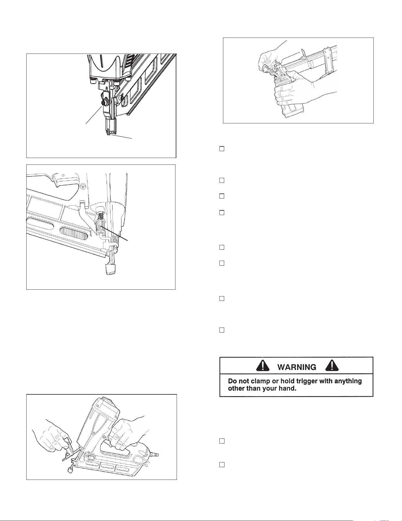
Clearing a Jam
An occasional problem you may encounter is a
jammed fastener. Because of the unique design
of the tool, clearing a jammed fastener is easy:
1. Disconnect the air supply.
2.
Pull the latch, releasing front guide. Pivot front
guide forward.
3.
Clear jam, and push driver blade back up to its
normal position.
4.
Close front guide and latch it. Check that the
work contacting element moves freely.
Turn
adjustment
wheel in either
direction
clearing a jam continued
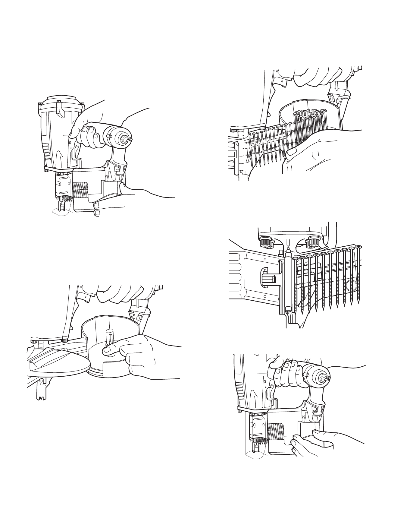
Coil Nailers
Step No. 1
– Grasp the nailer handle firmly with one
hand and with the other hand unlatch the
magazine
cover clip. Swing the magazine door open.
Step No. 2
– Adjust the loading tray for nail length (if
required) by depressing the button on the post and
raising or lowering the tray to the desired position.
Step No. 3 – Remove the retainer from a nail coil and
place the nail coil in the magazine with the tips of the nails
against the loading tray and with about 4 inches of coil
unwound.
Step No. 4
- Slide the free strip of nails along the top of
the feeder body assembly and place the first nail between
the feed claw and the locator.
Step No. 5
- Carefully close and latch the magazine door.
Step No. 6
- Advance the first nail into driving position by
cycling the tool once against a work surface. The nailer
is now ready for use.
7
T250-F16 Series Finish Nailer
Step No. 1 – Grasp the nailer firmly with one hand.
Step No. 2
– Insert the strip with the point of the
fastener facing down towards the bottom of the
magazine.
Step No. 3 – Hold the follower firmly and press the
follower latch. Slide the follower forward until it
contacts the nails. The tool is now ready for use.
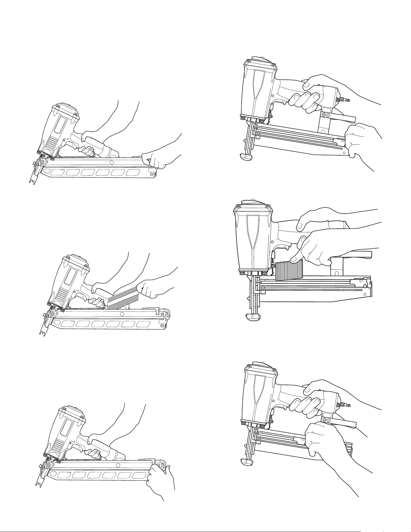
RHP-350
PowerMaster Plus
Strip Nailers
Step No. 1
– Grasp the nailer handle firmly. Pull the
magazine follower all the way to the rear of the
magazine until it is latched into its loading position
by the magazine latch.
Step No. 2 – Insert the a strip of fasteners into the
top of the magazine with the point of the nails facing
the nose area.
Step No. 3 – Hold the follower firmly and press the
follower latch. Slide the follower forward until it
contacts the nails.
8
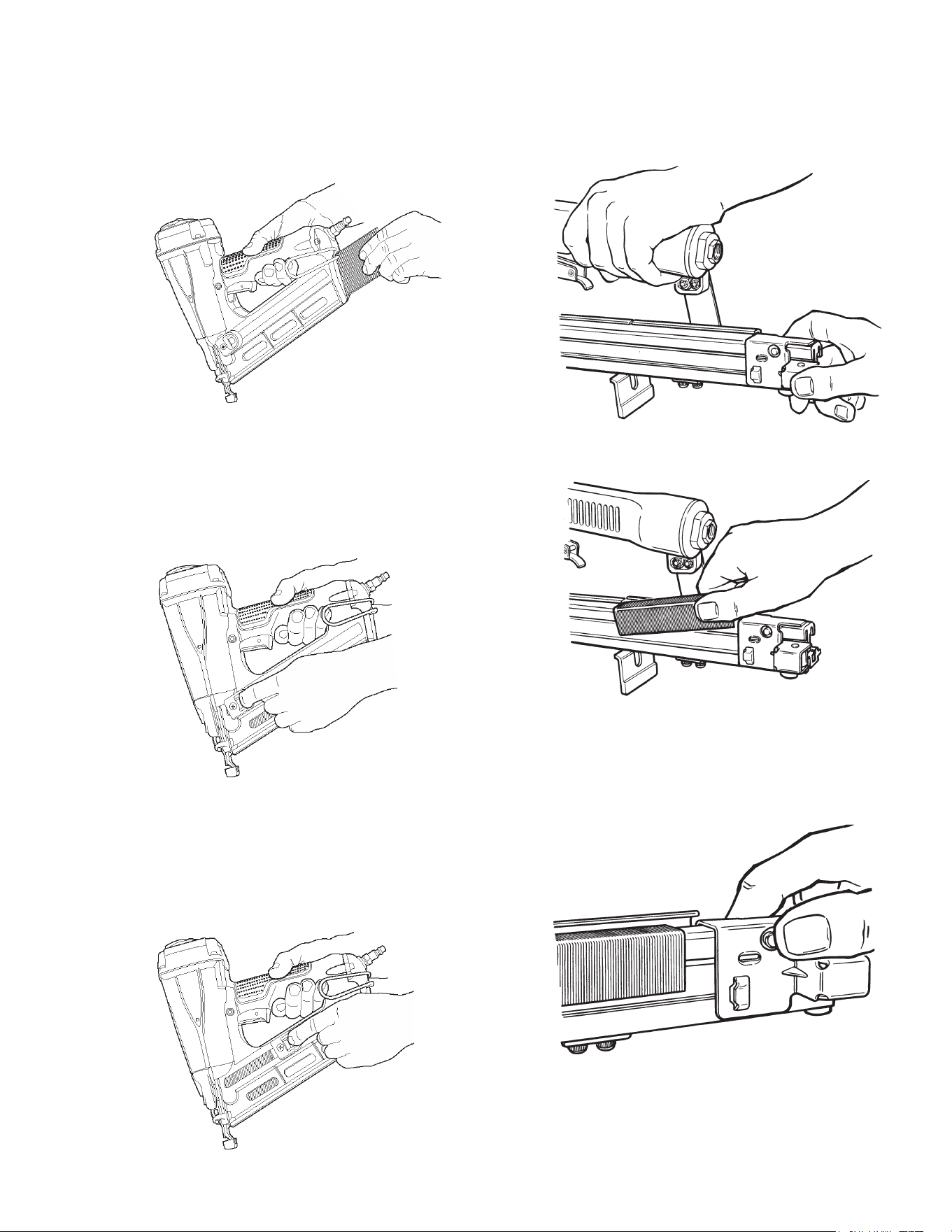
T250A-F16 Series Finish Nailer
Step 1
- Align the heads of the Paslode 16 ga.Finish
nails to the brad channel in the rear of the magazine
and insert one or two strips. Push the nails strips
forward.
Step 2
- Next, while applying pressure to the release
lever, pull the follower toward the rear of the magazine
until the follower passes the last strip of fasteners.
Release the lever on the follower and let the follower
push the nails forward into the nose of the tool.
Step No.3
When the follower reaches the reload area, marked
on the side of the magazine, you may insert a new
strip of nails. When the follower arrow reaches the
lockout area the tool automatically locks the tool to
prevent the tool from operating. To unlock the tool,
simply reload another strip of nails.
9
Staplers
Step No. 1 – Pull back the rail follower until it latches
at the end of the magazine. The rail cover will
automatically open.
Step No. 2
– Insert the fastener strip into the
magazine rail.
Step No. 3
– Press the follower latch release button
or unlatch the follower and slide the follower forward
until it contacts the staple strip. The tool is now
ready for use.
MAINTENANCE
Paslode
®
tools are built for ease of maintenance. A few
simple details will assure trouble-free operation and long
tool life. Anyone who uses or maintains the tool must read
the safety and maintenance instructions. Study the sche-
matic drawing before starting any repairs on the tool.
Air-operated tools must be inspected periodically, and
worn or broken parts must be replaced to keep the tool
operating safely and efficiently. Also the items on the
maintenance chart must be checked often.
Cold Weather Care
When temperatures are below freezing, tools should be
kept warm by any convenient, safe method. If this is not
possible, the following procedure should be used to warm
up the tools.
❑ Reduce the regulated air pressure to 30 psi.
❑ Remove all fasteners from the tool.
❑
Connect an air line and blank fire the tool. The reduced
air pressure will be enough to free-fire the tool. Slow
speed operation tends to warm up the moving parts.
slowing up the piston helps the bumper and the O-rings
to become springy.
❑ Once the tool is warmed up, readjust the regulator to
the proper working pressure and reload the tool.
❑
Tool operators working outdoors or in unheated areas
in extremely cold temperatures should also:
Use Paslode pneumatic oil with antifreeze in the
lubricator, Part No. 219090 (8oz.)
Once a week, depending on the amount of tool
use, take the tool apart and wash away any
sludge with tool cleaner (Paslode Part No. 219348)
to keep the tool operating efficiently.
Cleaning the air-operated tools with solvents removes the
thin coating of grease applied to the cylinder wall and
O-rings at the factory. To replace this coating of grease,
use Chemplex grease (Paslode Part No. 403734).
❑
Open the drain on the air compressor tank to drain any
moisture at least daily in extremely cold or humid weather.
A few ounces of anti-freeze in the tank will keep the air free
of frost.
Testing the Tool After Servicing
After replacing any part or parts, it is important to check
the tool for proper operation. This ensures that the tool
was put together correctly, is safe to use, and will perform
the job properly.
❑ Ensure that all hardware is tight.
❑
Ensure that the work contacting element is installed
correctly in relation to the trigger, and that both parts move
freely.
❑ Ensure that the magazine is properly attached.
❑
Ensure that the required safety information on the tool
is legible.
❑ Use only Paslode approved fasteners in the tool, and
ensure that they are correct for the application.
❑ Ensure that a male air fitting is securely connected to
the tool.
❑
Test the tool by driving fasteners into a workpiece
identical to the tool's application.
❑
Check the tool for air leaks during testing and for the
proper sequence of operation.
❑
Ensure that all fasteners are driven to the same depth
and that the crown of the fastener is flush with the work-
piece.
Tool Lubrication
It is most important that the tool be properly lubricated by
keeping the air line lubricator filled and correctly adjusted.
Without proper lubrication the tool will not work properly
and parts will wear prematurely.
Use the proper lubricant in the air line lubricator. The
lubricator should be of low air flow or changing air flow
type, and should be kept filled to the correct level. Use
only Paslode recommended lubricants. Substitutes may
harm the rubber compounds in the tools O-rings and other
rubber parts. Paslode Part No. 403720 is a pneumatic
lubricating oil specially made for pneumatic applications.
If a filter/regulator/lubricator is not installed on the air
system, air operated tools should be lubricated at least
once a day with 6 to 20 drops of oil, depending on the
work environment, directly through the male fitting in the
tool housing.
Most minor problems can be resolved quickly and easily
using the maintenance table that follows. If problems per-
sist, contact your Paslode dealer for assistance.
10

MAINTENANCE - Continued
Drain air line filter(daily).
Keep lubricator filled.
Clean filter element-then blow
air through filter in direction
opposite to normal flow.
Check that all screws on tool
are tight.
Keep work contacting elelment
working properly.
Keep magazine and feeder
mechanism clean.
Lubricate "O" rings that are
replaced.
Use only Paslode replacement
parts.
ACTION WHY HOW
MAINTENANCE TABLE
Prevent accumulation of
mositure and dirt.
Keep tool lubricated.
Prevent clogging of filter with
dirt.
Prevent air leakage and pro-
mote efficient operation.
Promote operator safety and
efficient tool operation.
Prevent jamming of fasteners.
Assure long life and proper
operation of tool.
Keep tool operating efficiently
and maintain Paslode tool
warranty.
Open manual petcock (most
air supply systems have such
a valve).
Fill with Paslode pneumatic
tool lubricant. Part No.
403720.
Wash with soap and water or
follow manufacturers instruc-
tions.
Check screws daily.
Blow clean daily.
Blow clean daily.
Use Chemplex grease, Part
No. 403734.
Order any replacement parts
needed from Paslode Dealer.
11
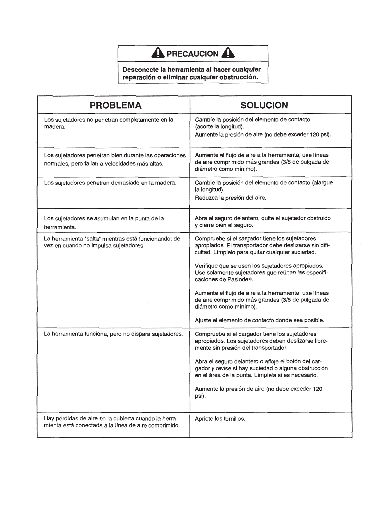
CAUTION
Disconnect the tool when performing
repairs or clearing jams.

OPERATOR TROUBLESHOOTING
PROBLEM CORRECTIVE ACTION
Fasteners will not drive completely into wood.
Fasteners penetrate properly during normal
operation, but won't drive fully at faster speeds.
Fasteners drive too deeply into wood.
Fastener jams in nose of tool.
Tools skips during operation - no fasteners are
driven from time to time.
Tool operates, but no fasteners are driven.
Air leaks at cap when tool is connected to air.
Adjust work contacting element (retract length).
Increase air pressure (do not exceed 120 psi).
Increase air flow to tool -- use larger air lines
(3/8 inch ID minimum).
Adjust work contacting element (extend length).
Reduce air pressure.
Open front guide latch, release jammed fastener,
and close latch securely.
Check magazine for proper fasteners. Magazine fol-
lower should slide freely. Clean as needed to remove
debris.
Make sure correct fasteners are being used.
Use fasteners that meet Paslode
®
specifications only.
Increase air flow to tool -- use larger air lines
(3/8 ID minimum).
Adjust work contacting element where available.
Check magazine for proper fasteners. Fasteners
should slide freely with no follower pressure.
Open front guide latch or loosen magazine knob and
check for jams or debris in the nose area. Clear as
necessary.
Increase air pressure (do not exceed 120psi).
Tighten capscrews.
CAUTION
Disconnect the tool when performing
repairs or clearing jams.
DETECCION Y CORRECCION DE FALLAS
12
An Illinois Tool Works Company
155 Harlem Avenue
Glenview,IL 60025
ONE-YEAR FULL WARRANTY
A one-year warranty will apply to all parts.
FIVE-YEAR EXTENDED LIMITED
WARRANTY
A five-year warranty will apply to all
housing and cap assembly castings.
TOOL WARRANTY
TOOL WARRANTY AND LIMITATIONS

PAn Illinois Tool Works Company
155 Harlem Avenue
Glenview, IL 60025
www.paslode.com
Printed in U.S.A.
© 2023, Illinois Tool Works, Inc.
For additional information on Paslode® products, visit our website at www.paslode.com.
For technical support call 1-800-222-6990.
To purchase parts and accessories, visit www.itwconstructionparts.com.
P
HERRAMIENTAS
NEUMATICAS
Manual de Operacion y Mantenimiento
P
P
P
DESIGNACION NUMERICA DE LOS MODELOS DE PASLODE
El número de modelo de cada una de las herramientas de Paslode contiene información sobre
la herramienta y los sujetadores adecuados para su uso. El siguiente ejemplo corresponde a
una herramienta típica.
ENGRAPADORA
Letra de serie
Longitud máxima del
sujetador (en pulgadas)
que se puede usar con
la herramienta
00 -
S 00 P
Tipo de herramienta
( P= unidad motriz)
( DL= doble longitud)
Calibre del sujetador
Indica el tamaño de la
cabeza
( W = ancha)
( S = estándar)
( I = intermedia)
( N = angosta)
Longitud máxima del sujetador
(en milímetros)
O
000
/
Paslode es miembro de:
CLAVADORA
Letra de serie
Longitud máxima del
sujetador (en pulgadas)
que se puede usar con
la herramienta
/
O
000
Tipo de herramienta
( C = clavadora para
sujetadores en rollos)
( S = para sujetadores
en tiras)
( F = de terminado)
( R = para techos)
Unidad motriz
C P
00
Longitud máxima del sujetador
(en milímetros)

INTRODUCCION
¡Felicitaciones por su acertada decisión de adquirir una herramienta neumática Paslode
®
!
Una herramienta Paslode es una herramienta de calidad que ofrece una combinación de potencia y
rapidez, en un diseño liviano, que permite diversas funciones en múltiples aplicaciones y en el camp
de la construcción.
Revise detenidamente este manual y toda la información relacionada con la herramienta, para poder
familiarizarse con su funcionamiento. Lea cudadosamente las instrucciones de seguridad antes de
usar su herramienta, así como la garantía que aparece al final del manual.
Aun cuando Paslode es líder en la fabricación de herramientas neumáticas, nos esforzamos constante-
mente en la búsqueda de nuevas formas de mejorar nuestros productos, ya que éste es el compromiso
que hemos contraído con nuestros clientes.
Paslode también fabrica una linea de herramienta "Impulse", sin cordon, que no aparecen en este
maunal. Consulte el manual sobre dichas herramientas con respecto a las instrucciones relacionadas
con matenimiento y seguridad
CONTENIDO
INTRODUCCION................................................................................................................. 1
INSTRUCCIONES DE SEGURIDAD................................................................................... 2
SISTEMAS NEUMATICAS.................................................................................................. 3
INSTALACIÓN DE LA HERRAMIENTA.............................................................................. 5
FUNCIONAMIENTO DEL LA HERRAMIENTA................................................................... 5
COMO CARGAR LA HERRAMIENTA................................................................................ 6
MANTENIMIENTO............................................................................................................... 9
DETECCION Y CORRECION DE FALLAS........................................................................12
GARANTIA.................................................................................................Contratapa interior
1
.
PELIGRO
La falta de observación de cualquiera de estas instrucciones puede ser causa de graves
lesiones personales, tanto al operador de la herramienta comoa quienes estén cerca de
ella o de daños materiales o a la herramienta
.
Comuníquese con el representante de Paslode sobre la presentación de Programa de Alerta sobre
Seguridad.
LA SEGURIDAD ESTA PRIMERO
Estas instrucciones proporcionan la información necesatia para
el funcionamiento sin peligrode las herramientas Paslode. NO
trate de usar su herramienta hasta que no haya léido y en-
tendido todas las precauciones de seguridad y las instruc-
ciones de este manual.
PROTEJASE LOS OJOS Y LOS OIDOS
Use siempre el equipo adecuado para protegerse
los ojos y los oídos que sea conforme con ANSI Z87+,
meintras usa una herramienta o trabaja cerca de una
herramienta en uso. Como empleador usted es respons-
able de imponer el usp del la porteccion de ojo. Lleve
sombreros duros en los ambientes que requieren su
uso.
USE SU HERRAMIENTA SOLAMENTE PARA EL
PROPOSITO CON QUE FUE DISEÑADA
No arroje la herramienta al suelo; no golpee el armazón ni la use
como un martillo.
NUNCA USE LA HERRAMIENTA PARA JUGUETEAR
Esta herramienta no es un juguete; por lo tanto no la trate como
tal. Nunca juguetee con ella, ni se apunte a usted mismo ni a
otra persona, aun cuando crea que no está cargada.
NUNCA ASUMAQUE LA HERRAMIENTA ESTA VACIA
Verfique que ho haya sujetadores en elcargador. Aun cuando
crea que está vacía o desconectada, nunca se apunte ni apunte
a otra persona con la herramienta, porque podría dispararse un
sujetador que no esté a la vista.
NUNCA SUJETE EL GATILLO EN LA POSICION DE
CIERRE O DE FUNCIONAMIENTO
Nunca se debe manipular indebidamente o dejar inoperante el
gatillo, o sujetarlo en la posición de cierre o defuncionamiento,
porque se podría disparar un sujetador al oprimirse el elemento
de contacto.
NO CARGUE SUJETADORES CUANDO LA LINEA DE
AIRE COMPRIMIDO ESTE CONECTADA, O CUANDO
EL GATILLO O EL ELEMENTO DE CONTACTO ESTE
OPRIMIDO.
Antes de cargar sujetadores en la herramienta, verifique que la
línea de aire comprimido esté desconectada y que ni el gatillo ni
el elemento de contacto estén oprimidos.
USE LA HERRAMIENTA SOLAMENTE SOBRE UN
MATERIAL DE TRABAJO
La herramienta debe funcionar sólo cuando esté en contacto
con el material de trabajo. Debe tener mucho cuidado cuando el
material sea delagado o trabaje cerca de las aristas del mismo,
porque los sujetadores podrían atravesar o salirse del material.
NO DEJE INOPERANTE NI QUITE EL ELEMENTO DE
CONTACTO
Esta herramienta está equipada con un mecanismo de seguri-
dad, llamado elemento de contacto, para prevenir cualquier disp-
aro accidental. Nunca manipule indebidamente, deje inoperante,
ni quite el elemento de contacto. No use la herramienta a menos
que dicho elemento funcione correctamente, porque podría
producirse un disparo imprevisto.
DESCONECTE LA HERRAMIENTA CUANDO NO
LA ESTE USANDO
Siempre desconecte la herramienta de la línea de aire
comprimido cuando no la esté usando o al dejar su lugar de
trabajo. Nunca la descuide, porque cualquier persona que no
esté familiarizada con ella podría lastimarse o lastimar otros.
TOME LA HERRAMIENTA SOLAMENTE POR EL
MANGO
Siempre tome la herramienta sólo por el mango. Nunca la
tome por la manguera o con el gatillo oprimido, porque se
podría disparar un sujetador y herirlo o herir a otra persona.
NO ALTERE EL ARMAZON DE LA HERRAMIENTA
El armazón de la herramienta es un recipiente a presión y nunca
se debe grabar en su superficie el nombre de su compañia, el
del área de trabajo, ni ningún otro detalle.
DESCONECTE LA HERRAMIENTA PARA HACER
REPARACIONES O ELIMINAR OBSTRUCCIONES
Nunca trate de eliminar obstrucciones o reparar una herra-
mienta sin haberla desconectado de la línea de aire compromido
y quitado todos los sujetadores.
USE SIEMPRE LOS ADAPTADORES APROPIADOS
PARA SU HERRAMIENTA
Se debe conectar a la herramienta solamente conectores
neumáticos MACHOS, para permitir que el aire de alta pre-
síon salga tan pronto como se desconecte la línea de aire
comprimido.
NUNCA coloque enlaces HEMBRAS de desconexíon rápida
en la herramienta, porque atrapan el aire a alta presíon al
desconectar la línea de aire comprimido, dejándola cargada y
lista para disparar por lo menos un sujetador.
NO EXCEDA LA PRESION NEUMATICA MAXIMA
RECOMENDADA
La herramienta debe funcionar sólo con la presíon neumática re-
comendada. No exceda la presíon neumática máxima marcada
en la herramienta. Verifique por lo menos dos veces al día que
el calibre de la presíon neumática funcione correctamente.
Nuna use aire o gases envasado, como el oxígeno, para hacer
funcionar la herramienta porque podrían hacer que explotara.
No haga funcionar en atmósferas explosivas.
INSPECCIONE LA HERRAMIENTA PARA LA OPERA-
CION APROPIADA
Limpie diariamente la herramienta y lubríquela como se re-
comienda. Nunca trate de hacer funcionar una herramien
ta
sucia o defectuosa.
USE SOLAMENTE PIEZAS Y SUJETADORES RECO-
MENDADOS POR PASLODE
Use sólo piezas y sujetadores específicamente diseñados y
recomendados por Paslode para usar con esa herramienta
y para la tarea requerida. Si se usan piezas o sujetadores no
autorizados o se modifica de alguna forma la herramienta, se
pueden crear situaciones peligrosas. Vuelva a colocar todas
las etiquetas de precaucíon que flaten. Consulte el diagrama
de la herramienta sobre el número de cada parte y su ubli-
gación correcta.
INSTRUCCIONES DE SEGURIDAD
2
SISTEMAS NEUMATICOS
3
SISTEMAS NEUMATICOS
(continuación)
4
INSTALACION DE LA
HERRAMIENTA
FUNCIONAMIENTO DE LA
HERRAMIENTA
5
FUNCIONAMIENTO DE LA
HERRAMIENTA
(continuación)
Suba para
aumentar la
profundidad de
colocacion
Baje para
disminuir la
profundidad de
colocacion
Tornillo con
cabeza de casquillo
adaptador
Elemento de contacto
➔
➔
6
Para desatorar la clavadora
Un problema típico que puede encontrar es una
clavadora con clavos atorados. Debido al diseño
único de la clavadora Paslode, es muy sencillo sacar
los clavos atorados:
1. Disconecte el aire.
2. Deslice el seguro para soltar la quía delantera
y hágala pivotear hacia adelante.
3. Quite las clavos atorados y empuje la hoja del
impulsador hacia atrás hasta la posición normal
de retorno.
4. Cierre la guía delantera y asegúrela. Verifique
que el elmento de contacto no esté obstruido.
Turn
adjustment
wheel in either
direction
para desatora la clavadora (continuación)
(Naranjado)
(Naranjado)
(Gris)
COMO CARGAR LA
HERRAMIENTA
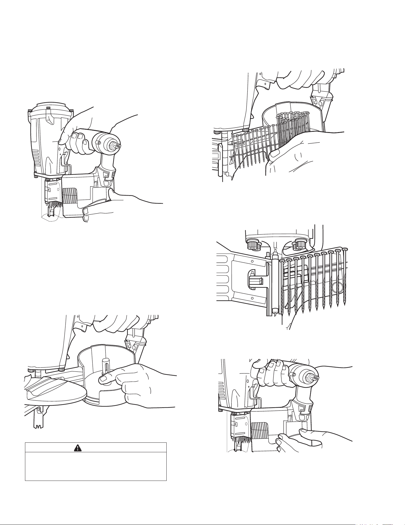
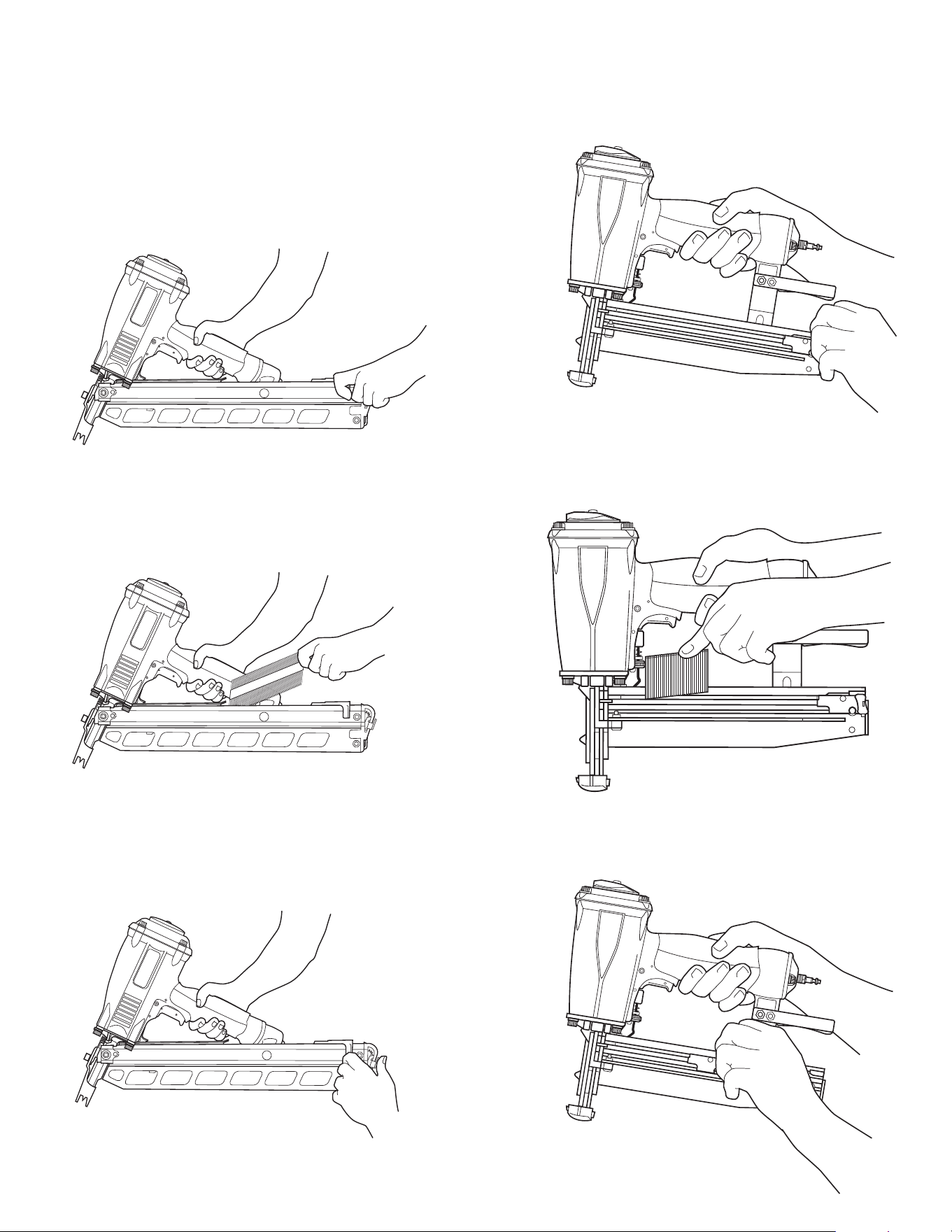
Clavadora de Rollo de clavos
Paso 1: Tome firmemente la clavadora por el
mango con una mano y con la otra abra la pinza
de la cubierta del cargador. Despoés abra bien la
puerta del cargador.
Paso 2: Si fuera necesario, adapte la bandeja del
cargador a la longitud de los clavos, sacándola
un poquito para poder levantarla o bajarla a la
posicíon deseada.
Paso 3: Quite el retén de un rollo de clavos y coloque el
rollo en el cargador, de modo que la punta de los clavos se
apoye en la bandeja, teniendo unos 10 cm de clavos desen-
rollados.
Paso 4: Haga deslizar la tira de clavos desenrollada a lo
largo de la parte superior del alimentador: ponga el primer
clavo entre el gancho del alimentador y localizador.
Paso 5: Cierre cuidadosamente la puerta del cargador y
póngale el seguro.
Paso 6: Empuje hacia adelante el primer clavo hasta la
posición de impulso, haciendo adelantar la herramienta un
ciclo contra la superficie de trabajo. La clavadora está ahora
lista para usarse.
PELIGRO
Tenga cuidado de no sacar demasiado la
bandeja, porque se podría desenganchar y
estirar el resorte.
Coil Nailers
Step No. 1
– Grasp the nailer handle firmly with one
hand and with the other hand unlatch the
magazine
cover clip. Swing the magazine door open.
Step No. 2
– Adjust the loading tray for nail length (if
required) by depressing the button on the post and
raising or lowering the tray to the desired position.
Step No. 3 – Remove the retainer from a nail coil and
place the nail coil in the magazine with the tips of the nails
against the loading tray and with about 4 inches of coil
unwound.
Step No. 4
- Slide the free strip of nails along the top of
the feeder body assembly and place the first nail between
the feed claw and the locator.
Step No. 5
- Carefully close and latch the magazine door.
Step No. 6
- Advance the first nail into driving position by
cycling the tool once against a work surface. The nailer
is now ready for use.
7
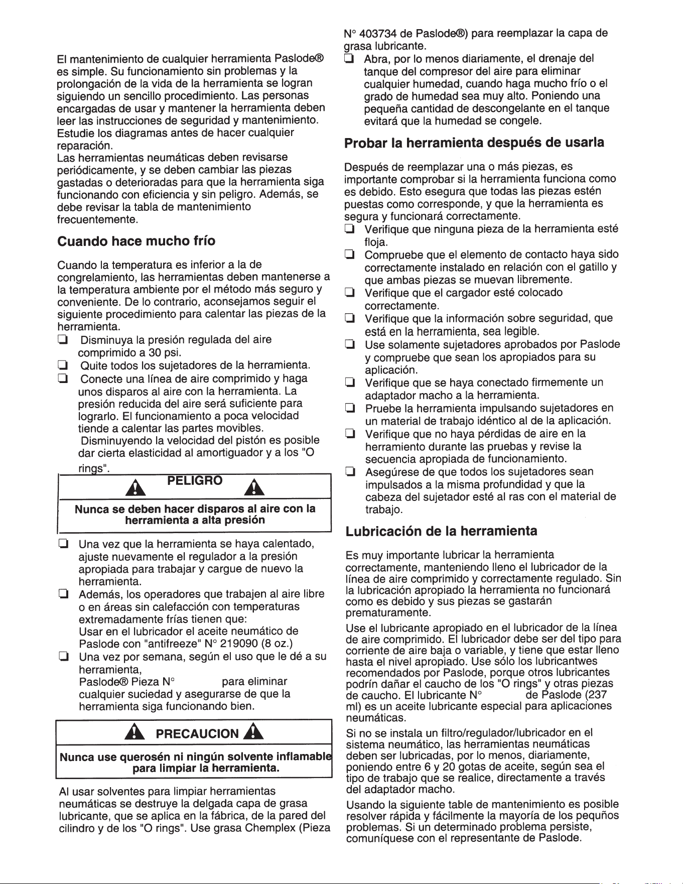
Grapadora de serie T250-F16
Paso 1: Tome la clavadora firmemente con una
mano.
Paso 2: Coloque la tira de modo que la punta de
sujetadores quede hacia abajo del cargador.
Paso 3: Empuje firmemente el cargador hacia
adelante hasta que esté asegurado. La herramienta
ya está lista para usarse.
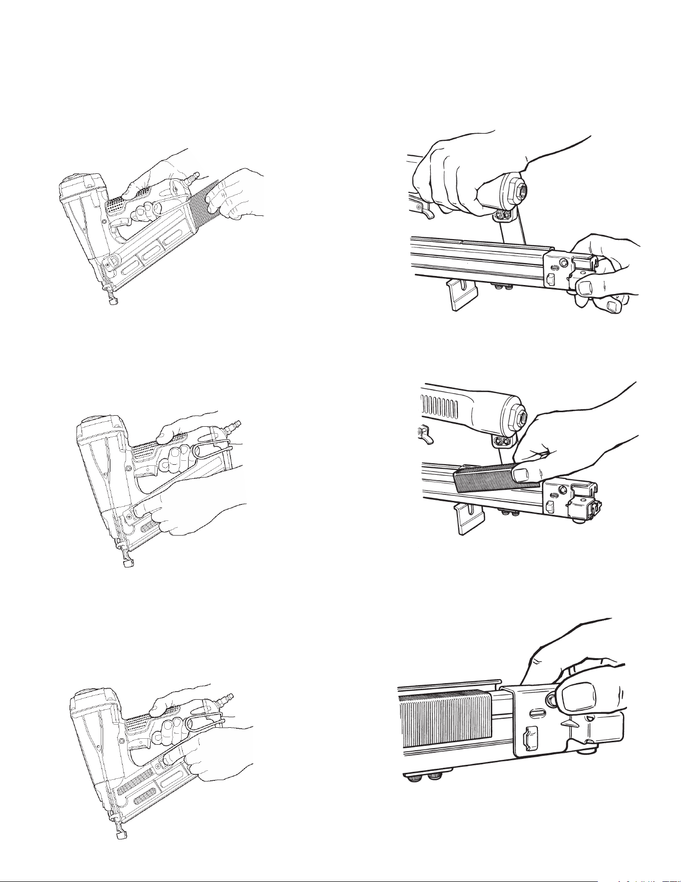
Clavadoras RHP-350 y
PowerMaster Plus™
Paso 1: Agarre con firmeza el mango de la clavadora.
Tire del transportador del cargador completamente
hacia la parte trasera del cargador hasta que se
enganche en su posición de carga por medio del
seguro del cargador.
Paso 2: Coloque una tira de sujetadores en la parte
superior del cargador, do modo que la punta de los
clavos quede hacia el area de la punta de la
herramienta.
Paso 3: Sujete el transportador con firmeza y oprima
el seguro del transportador. Deslice el transportador
hacia adelante hasta que haga contacto con los
clavos. La herramienta está ahora lista para usarse.
8
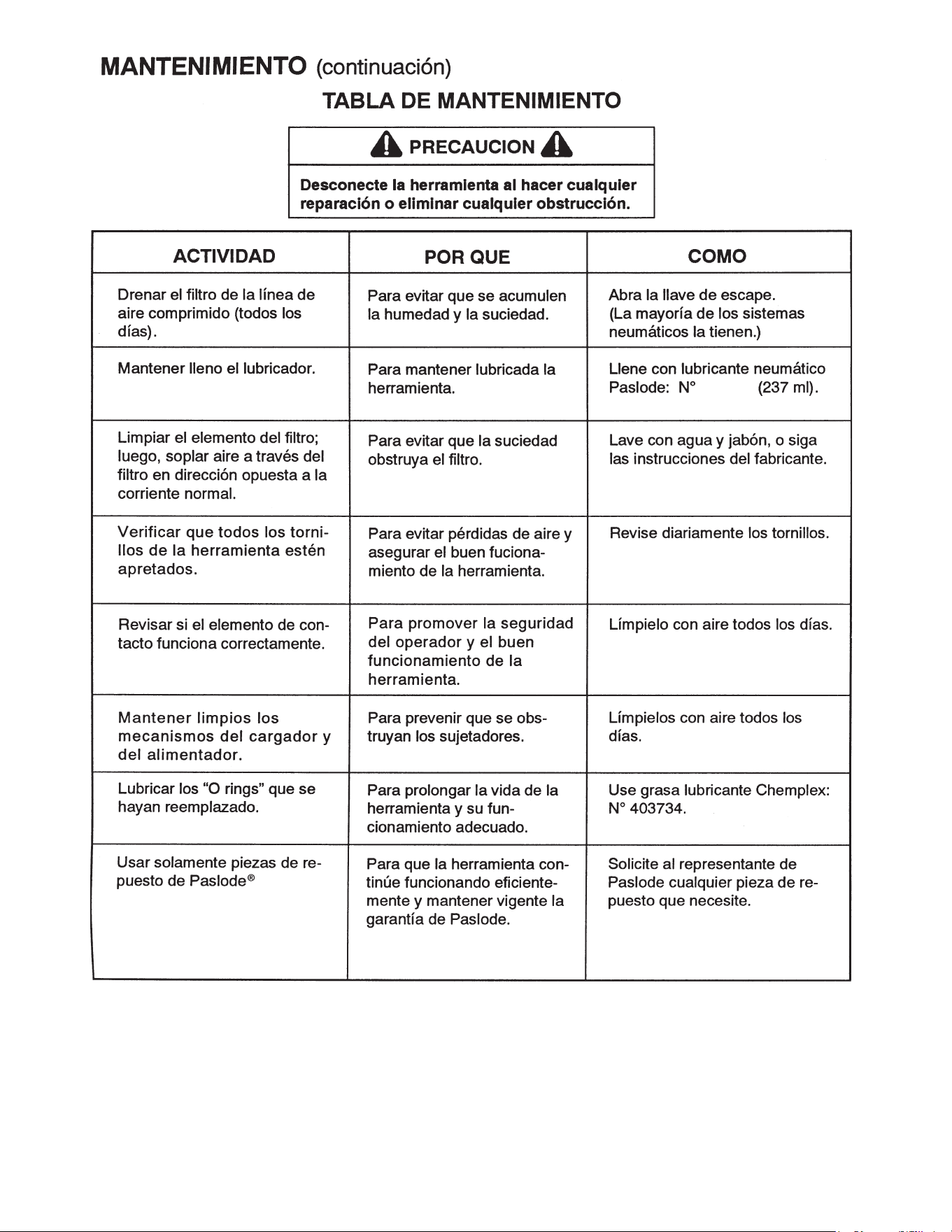
Grapadora de serie T250A-F16
Paso 1: Alinee las cabezas del los clavos de aca-
bado angulados Paslode con el canal de clavitos
plateado en la parte posterior del cargador e intro-
duzca una o dos tiras. Empuje las tiras de clavos
hacia adelante.
Paso 2: Luego, mientras oprime la palanca de
liberación, tire del seguidor hacia la parte posterior
del cargador hasta que el seguidor haya pasado la
última tira de clavos. Suelte la palanca del seguidor
y deje que el mismo mueve los clavos hacia adelan-
te dentro de la boca de la herramienta.
Paso 3: Cuando la flecha aparezca en el área de
recarga, marcada en el lado del cargador, usted
puede introducir una nueva tira de clavos. Cuando
la flecha de seguidor alcance al área de bloqueo,
la herramienta se bloquea automáticamente para
evitar su funcionamiento. Para desenganchar la her-
ramienta, recargue simplemente otra tira de clavos.
9
GRAPAS
Paso 1: Tire del transportador del riel hasta que
quede asegurado en el extremo del cargador. La
cubierta del riel se abrirá automáticamente.
Paso 2: Coloque la tira de grapas en el riel del
cargador.
Paso 3: Apriete el botón de apertura del se-
guro del transportador, o abra el transportador y
hágalo deslizar hacia adelente hasta ponerlo en
contacto con la tira de grapas. La herramienta
está ahora lista para usarse.
Grapadora de serie T250-F16
Paso 1: Tome la clavadora firmemente con una
mano.
Paso 2: Coloque la tira de modo que la punta de
sujetadores quede hacia abajo del cargador.
Paso 3: Empuje firmemente el cargador hacia
adelante hasta que esté asegurado. La herramienta
ya está lista para usarse.
Clavadoras RHP-350 y
PowerMaster Plus™
Paso 1: Agarre con firmeza el mango de la clavadora.
Tire del transportador del cargador completamente
hacia la parte trasera del cargador hasta que se
enganche en su posición de carga por medio del
seguro del cargador.
Paso 2: Coloque una tira de sujetadores en la parte
superior del cargador, do modo que la punta de los
clavos quede hacia el area de la punta de la
herramienta.
Paso 3: Sujete el transportador con firmeza y oprima
el seguro del transportador. Deslice el transportador
hacia adelante hasta que haga contacto con los
clavos. La herramienta está ahora lista para usarse.
8
11
403720
11
403720
MANTENIMIENTO
403720
10
desármar y lávela con limipiador de
219348
11
403720
11
403720
DETECCION Y CORRECCION DE FALLAS
12

13
GARANTÍA
TERMINOS DE LA GARANTÍA
Paslode asume únicamente la responsabilidad de re-
poner cualquier pieza o accesorio que se compruebe
como defectuoso dentro del período especificado.
Cualquier pieza o accesorio de repuesto, entregado de
conformidad con esta garantía, gozará de la garantía por
el período restante de la garantía que cubría a la pieza o
al accesorio originales. Esta garantía no cubre las piezas
que necesitan ser repuestas como consecuencia de su
desgaste normal.
Se cancelará esta garantía a cualquier herramienta que
haya sido usada incorrectamente, dañada accidental o
intencionalmente, usada con sujetadores, combustible,
baterías o cargadores de batería que no reúnan las
especificaciones, el tamaño o la calidad de Paslode, o
a la que no se le haya dado el mantenimiento o el uso
adecuado, o que haya sido reparada con piezas que no
sean marca Paslode, o que en opinión de Paslode hayan
sido modificadas o reparadas de manera que afecte o sea
contraria al funcionamiento de la herramienta.
PASLODE NO OTORGA NINGUNA GARANTÍA EX-
PLÍCITA O IMPLÍCITA CON RESPECTO A LA COMER-
CIALIZACIÓN O ADAPTACIÓN AL USO PREVISTO, O
DE CUALQUIER OTRA NATURALEZA, CON EXCEP-
CIÓN DE LO DECLARADO ANTERIORMENTE, y la
responsabilidad de Paslode TAL COMO SE INDICA Y
SE ASUME MÁS ARRIBA reemplaza a todas las otras
garantías que resulten o estén relacionadas con el uso
y funcionamiento de la herramienta, excepto según lo
estipulen las leyes pertinentes. PASLODE NO SERÁ
RESPONSABLE EN NINGÚN CASO POR NINGÚN
DAÑO DIRECTO, INDIRECTO O CONSECUENTE
INCLUYENDO, PERO SIN LIMITARSE, CUALQUIER
DAÑO RESULTADO DE LA PÉRDIDA DE PRODUC-
CIÓN O GANANCIAS ANTICIPADAS, EL DETERIORO
DE MATERIALES, AUMENTOS EN EL COSTO DE OP-
ERACIÓN O CUALQUIER OTRO.
Paslode se reserva el derecho de cambiar las especificacionnes, el equipo o los
diseños en cualaquier momento, sin aviso previo y sin incurrir en obligación alguna.
• Amortiguador
• Hojas del impulsor
• “O rings”
• Anillos del pistón
DECLARACIÓN DE LA GARANTÍA
Esta garantía esta limitada a las herramientas vendi
das y revisadas en los Estados Unidos. Para obtener
más información sobre el ser
vicio de garantía en los
Estados Unidos, véa la lista de Centros de Servicio
que fue proporcionada con su herramienta.
Paslode
®
garantiza que sus herramientas mecánicas,
sus piezas y accesorios, que hayan sido comprados
nuevos, están libres de defectos de material y fabri-
cación por el período indicado más abajo, a partir
de la fecha de compra del comprador original.
GARANTIA COMPLETA DE UN ANO
Se aplicara una garantia de un ano a todas las piezas.
GARANTIA LIMITADA EXTENDIDA DE CINCO ANOS
Se aplicara una garantia de cinco anos a todas las
piezas fundidas del ensamblaje de la carcasa y la tapa.
PIEZAS DE DESGASTE NORMAL
Las siguientes piezas se consideran como piezas
que sufren desgaste normal y no están cubiertas
por
ninguna garantía.
®
®
An Illinois Tool Works Company
155 Harlem Avenue
Glenview,IL 60025

PAn Illinois Tool Works Company
155 Harlem Avenue
Glenview, IL 60025
www.paslode.com
Printed in U.S.A.
© 2023, Illinois Tool Works Inc.
Para la información adicion al en Paslode los productos, visitan nuestro sitio web
en www.paslode.com.
Para llama da técnica de apoyo 1-800-222-6990.
Para comprar las partes y los accesorios, la visita www.itwconstructionparts.com
®