

CORDLESS XPRO 30°
FRAMING NAILER
OPERATING MANUAL
Part No. 906800; 906800DHL
www.paslode.com
Model CF325XPRO24
IMPORTANT!
DO NOT DESTROY
It is the customer’s responsibility to have
all operators and service personnel read
and understand this manual.
Printed in U.S.A.
©2024 Illinois Tool Works Inc.
906867-1
08/24
1
Contents
The battery charger system meets all safety requirements for power tools.
Paslode® is a member of:
RBRC
RBRC
Li-ion
Power Nailers are designed and assembled in the U.S.A.
is a registered trademark of Illinois
Tool Works Inc. © 2024
An Illinois Tool Works Company
155 Harlem Avenue
Glenview, IL 60025
www.paslode.com
Subject Page
Introduction and Warranty . . . . . . . . . . . . . . . . . . . . . . . . . . . . . . . . . . . . . . . . . . . . . . . . . . . . . . . . . . . . . . . . . . . . . . . . . . . . . . . . . . . . . . . . . . . . . . . . . . . . . . . . . . . . . . . . . . . 2
An Overview of the Paslode Cordless Framing Nailer . . . . . . . . . . . . . . . . . . . . . . . . . . . . . . . . . . . . . . . . . . . . . . . . . . . . . . . . . . . . . . . . . . . . . . . . . . . . . . . . . . 3
Safety Instructions . . . . . . . . . . . . . . . . . . . . . . . . . . . . . . . . . . . . . . . . . . . . . . . . . . . . . . . . . . . . . . . . . . . . . . . . . . . . . . . . . . . . . . . . . . . . . . . . . . . . . . . . . . . . . . . . . . . . . . . . . . . . 5
Battery and Charging System . . . . . . . . . . . . . . . . . . . . . . . . . . . . . . . . . . . . . . . . . . . . . . . . . . . . . . . . . . . . . . . . . . . . . . . . . . . . . . . . . . . . . . . . . . . . . . . . . . . . . . . . . . . . . . . 8
Fuel Cell and Metering Valve . . . . . . . . . . . . . . . . . . . . . . . . . . . . . . . . . . . . . . . . . . . . . . . . . . . . . . . . . . . . . . . . . . . . . . . . . . . . . . . . . . . . . . . . . . . . . . . . . . . . . . . . . . . . . . . 10
Preparing the Paslode Cordless Framing Nailer for Use . . . . . . . . . . . . . . . . . . . . . . . . . . . . . . . . . . . . . . . . . . . . . . . . . . . . . . . . . . . . . . . . . . . . . . . . . . . . . . 13
Paslode Cordless Framing Nailer Operation . . . . . . . . . . . . . . . . . . . . . . . . . . . . . . . . . . . . . . . . . . . . . . . . . . . . . . . . . . . . . . . . . . . . . . . . . . . . . . . . . . . . . . . . . . . . 14
Fasterners and Applications. . . . . . . . . . . . . . . . . . . . . . . . . . . . . . . . . . . . . . . . . . . . . . . . . . . . . . . . . . . . . . . . . . . . . . . . . . . . . . . . . . . . . . . . . . . . . . . . . . . . . . . . . . . . . . . . 15
Servicing . . . . . . . . . . . . . . . . . . . . . . . . . . . . . . . . . . . . . . . . . . . . . . . . . . . . . . . . . . . . . . . . . . . . . . . . . . . . . . . . . . . . . . . . . . . . . . . . . . . . . . . . . . . . . . . . . . . . . . . . . . . . . . . . . . . . . . . 16
Tool Schematic. . . . . . . . . . . . . . . . . . . . . . . . . . . . . . . . . . . . . . . . . . . . . . . . . . . . . . . . . . . . . . . . . . . . . . . . . . . . . . . . . . . . . . . . . . . . . . . . . . . . . . . . . . . . . . . . . . . . . . . . . . . . . . . . 18
Troubleshooting . . . . . . . . . . . . . . . . . . . . . . . . . . . . . . . . . . . . . . . . . . . . . . . . . . . . . . . . . . . . . . . . . . . . . . . . . . . . . . . . . . . . . . . . . . . . . . . . . . . . . . . . . . . . . . . . . . . . . . . . . . . . . 20
Cleaning Procedure URL . . . . . . . . . . . . . . . . . . . . . . . . . . . . . . . . . . . . . . . . . . . . . . . . . . . . . . . . . . . . . . . . . . . . . . . . . . . . . . . . . . . . . . . . . . . . . . . . . . . . . . . . . . . . . . . . . . . . 21
2
Introduction and Warranty
Paslode Cordless Framing Nailer Operating
Manual
This manual is intended to acquaint you with the
Paslode® Cordless Framing Nailer. Unlike other
power fastening tools, the Cordless Framing Nailer
is powered by an internal combustion linear motor.
In simpler terms, your Cordless Framing Nailer is
powered by a motor similar to the one that powers
an automobile. The Cordless Framing Nailer ignites
a fuel and air mixture to produce the energy to drive
the motor, which in turn drives the fastener. As you
will see, the Cordless Framing Nailer is totally
self-contained. It carries its own fuel supply and
battery, along with a supply of fasteners.
For ease of use, this manual is divided into sections
(see Contents). Each section of the manual is
written with you, the tool operator, in mind. We have
left out all of the technical terms so that you can
readily under- stand how to get the maximum
performance from your Cordless Framing Nailer,
and how to avoid damaging the tool or injuring
yourself. But, to accomplish this, we need you to do
two things:
Paslode warranties that new Cordless power
fastening tools, parts and accessories will be free
from defects in material and workmanship for the
period shown below, after the date of delivery to
the original user.
ONE-YEAR LIMITED WARRANTY
A one-year warranty will apply to all parts, except
those specifically covered by an extended
warranty.
FIVE-YEAR EXTENDED LIMITED WARRANTY
A five-year warranty will apply to all molded nylon
parts:
• Motor Housing, Cap, and Grille
• Handle Halves and Actuator
• Trigger
• Magazine Parts
WARRANTY STATEMENT
This warranty is limited to tools sold and service requested in the
United States. To obtain information on warranty service in the
United States, refer to the Service Center listing that was provided
with your tool.
Paslode’s sole liability hereunder will be to replace any part or accessory
which proves to be defective within the specific time period. Any
replacement part or accessory provided in accordance with this
warranty will carry a warranty for the balance of the period of warranty
applicable to the part it replaces. This warranty does not apply to part
replacement required due to normal wear.
This warranty is void on any tool which has been subjected to misuse,
abuse, accidental or intentional damage, use with fasteners, fuel,
batteries, or battery chargers not meeting Paslode specification, size, or
quality, improperly maintained, repaired with other than genuine Paslode
replacement parts, damaged in transit or handling, or which, in Paslode’s
opinion, has been altered or repaired in a way that aects or detracts
from the performance of the tool.
PASLODE MAKES NO WARRANTY, EXPRESSED OR IMPLIED,
RELATING TO MERCHANTABILITY, FITNESS OR OTHERWISE,
EXCEPT AS STATED ABOVE, and Paslode’s liability AS STATED
ABOVE AND AS ASSUMED ABOVE is in lieu of all other warranties
arising out of, or in connection with, the use and performance of the
tool, except to the extent otherwise provided by applicable law.
PASLODE SHALL IN NO EVENT BE LIABLE FOR ANY DIRECT,
INDIRECT, OR CONSEQUENTIAL DAMAGES, INCLUDING, BUT NOT
LIMITED TO, DAMAGES WHICH MAY ARISE FROM LOSS OF
ANTICIPATED PROFITS OR PRODUCTION, SPOILAGE OF MATERI-
ALS, INCREASED COST OF OPERATION, OR OTHERWISE.
Paslode reserves the right to change specifications, equipment or
designs at any time without notice and without incurring obligation.
1. READ THE MANUAL FROM COVER TO COVER
BEFORE USING THE TOOL.
2. FOLLOW ALL INSTRUCTIONS IN THE
MANUAL.
The Cordless Framing Nailer should be handled like
other power fastening tools that you use. Like most
tools, when used improperly it could result in injury.
If you are going to allow others to use the Cordless
Framing Nailer, it is your responsibility to make sure
that they also read and comply with the instructions
in this manual before attempting to operate the tool.
Should you have questions about the Cordless
Framing Nailer, contact Technical Support at:
Email: tech@paslode.com
Phone: 800-222-6990.
For the most updated version
of this manual, always refer to
the digital code below:
Paslode Cordless Warranty and Limitations
CORDLESS 2 YEAR SERVICE PROMISE
Paslode will service the tool and replace all parts (including
battery and charger system) which have failed during normal
use for FREE for a period of 2 years from date of purchase.
For 2 Year Service Promise details and limitations see
paslode.com/service-and-support
3
Overview of the Paslode Cordless
Framing Nailer
Description
The Paslode Cordless Framing Nailer is a self-con-
tained, fully portable nailer that uses liquid hydro-
carbon fuel to power a unique linear drive internal
combustion motor.
As with any internal combustion motor, the Paslode
Cordless Nailer will require periodic maintenance to
keep it operating at it's peak performance. The
cleaning manual will instruct you on the proper
cleaning of your tool. If additional services are
required, contact your local Paslode
service provider.
This Paslode Cordless Nailer can be operated in
sequential and rapid fire mode.
NOTE: Altitude Restriction
Paslode Cordless tools are powered by an internal
combustion engine and are aected by altitude. The
tool may lose power or not cycle consistently at
elevations of 6000 feet (1,828 meters) or greater.
Specifications
Dimensions:
Weight (with battery) 7.9 pounds (3.6 Kg)
Length 12 inches (305mm)
Width: 5 inches (127mm)
Height 14-1/2 inches (368mm)
Cycle Rate: Intermittent Operation – 2 to 3
nails/second
Maximum Cycle Rate: 1,000 shots per hour
NOTE: Exceeding these rates could cause tool to
overheat, resulting in loss of performance or
damage to tool components.
By using the Paslode Cordless Framing Nailer at
its recommended cycle rate, you will be able to
drive several thousand nails in a typical workday.
Fasteners: 30° paper tape collation
Minimum 2 inch x .113 dia. shank (50 x 2.87mm)
Maximum 3-1/4 inch x .131 dia.shank (90 x
3.15mm)
Magazine Capacity: 1 nail strip + 5 nails.
Battery : 7V DC - Provides enough energy to
drive approximately 6000 fasteners on a full
charge.
Fuel Cell: Paslode Framing Fuel Cell. Liquid
hydrocarbon- Provides enough fuel to drive
approximately 1200 fasteners.
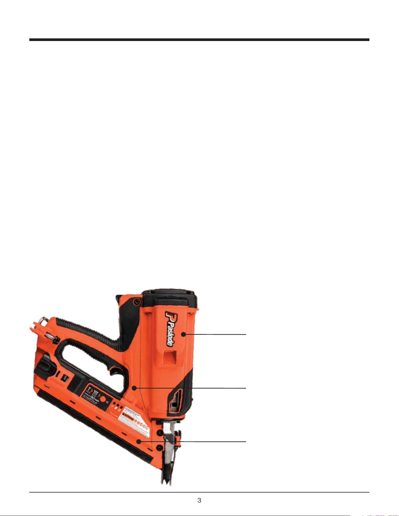
Motor
Assembly
Handle
Assembly
Magazine
Assembly
4
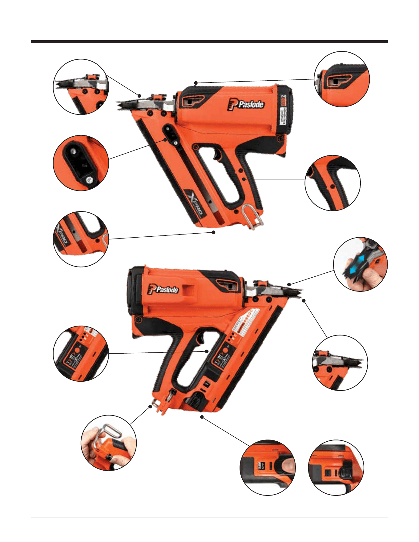
QUICK RELEASE-
NOSE PLATE ASSEMBLY
BYPASS FOLLOWER
EASY-LOAD MAGAZINE
TOOL REST FIXTURE
ADJUSTABLE UTILITY HOOK
BATTERY OFF / ON
DEPTH OF DRIVE
ADJUSTMENT
WORK CONTACTING ELEMENT
WITH AGGRESIVE TIP FOR
TOE-NAILING
SOFT GRIP HANDLE
LED PANEL SHOWING
BATTERY STATUS AND
FIRING MODE
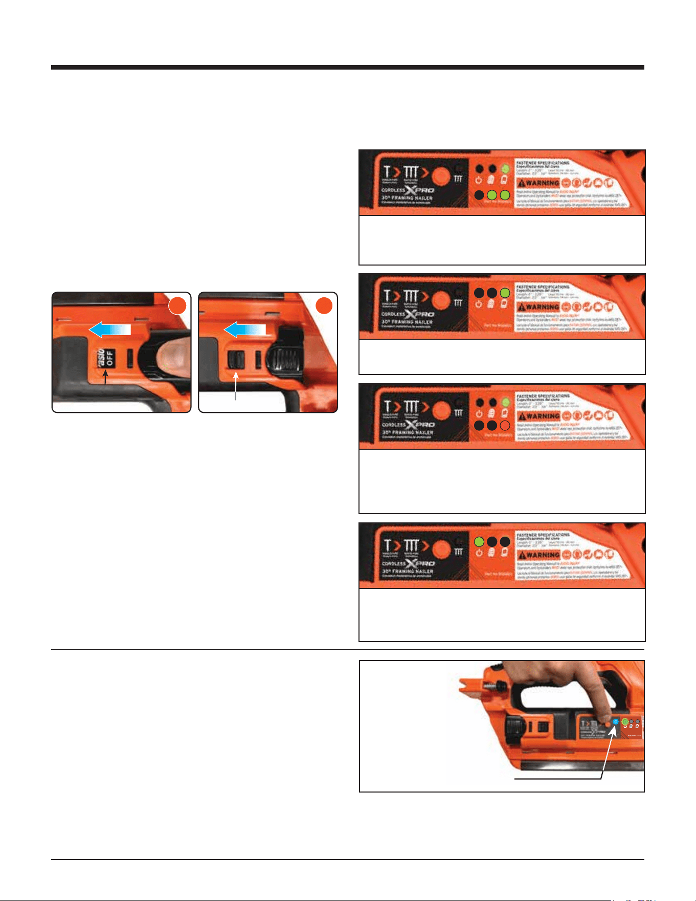
OFF ON
Overview of the Paslode Cordless
Framing Nailer
5
WARNING
Safety Instructions
The following safety instructions have been includ-
ed in this booklet to provide you with basic informa-
tion necessary for safe operation of the Paslode
Cordless XPro 30º Framing Nailer.
In addition to these instructions, there is additional
training content on Paslode.com
DO NOT ATTEMPT TO OPERATE THIS TOOL
UNTIL YOU HAVE READ AND UNDERSTAND
ALL SAFETY PRECAUTIONS AND MANUAL
INSTRUCTIONS.
1. Eye protection must meet the requirements of
ANSI Z87+ and should have side shields for
increased protection.
2. NEVER ASSUME THE TOOL IS EMPTY.
3. NEVER ENGAGE IN “HORSEPLAY” WITH THE
TOOL.
The Cordless Nailer is not a toy – it is a tool.
Careless and improper use may result in a
serious accident.
4. NEVER CARRY THE TOOL WITH YOUR
FINGER ON, OR SQUEEZING THE TRIGGER.
This practice may result in the accidental
discharge of a fastener.
5. NEVER OPERATE A MALFUNCTIONING TOOL.
Refer to the servicing or troubleshooting section
of this manual to correct the problem. If the
problem cannot be corrected, stop using the tool
and report it to your supervisor or Paslode
representative.
6. DO NOT LOAD FASTENERS WITH THE TRIG-
GER AND/OR WORK CONTACTING ELEMENT
PRESSED IN.
A fastener may be accidentally discharged.
7. NEVER OPERATE THE TOOL WITH THE WORK
CONTACTING ELEMENT REMOVED OR
DISABLED.
This device helps reduce the possibility of acci-
dental fastener discharge by preventing the tool
from operating until it is completely against the
work surface.
NEVER operate the tool if the Work Contact
Element is not working properly.
8. ALWAYS POINT THE TOOL AWAY FROM
YOURSELF AND OTHERS WHEN CLEARING A
JAM OR REMOVING FASTENERS.
Pull the follower slightly back and push the
release lever. Tip the tool nose up slightly and
fasteners should slide out of the rear of the
magazine. If fasteners are jammed, refer to the
appropriate servicing section of this manual.
9. NEVER OPERATE THE NAILER IF PARTS ARE
LOOSE, DAMAGED OR MISSING.
10. DO NOT DRIVE FASTENERS INTO KNOTS OR
ON TOP OF OTHER FASTENERS.
A fastener may ricochet and cause serious injury.
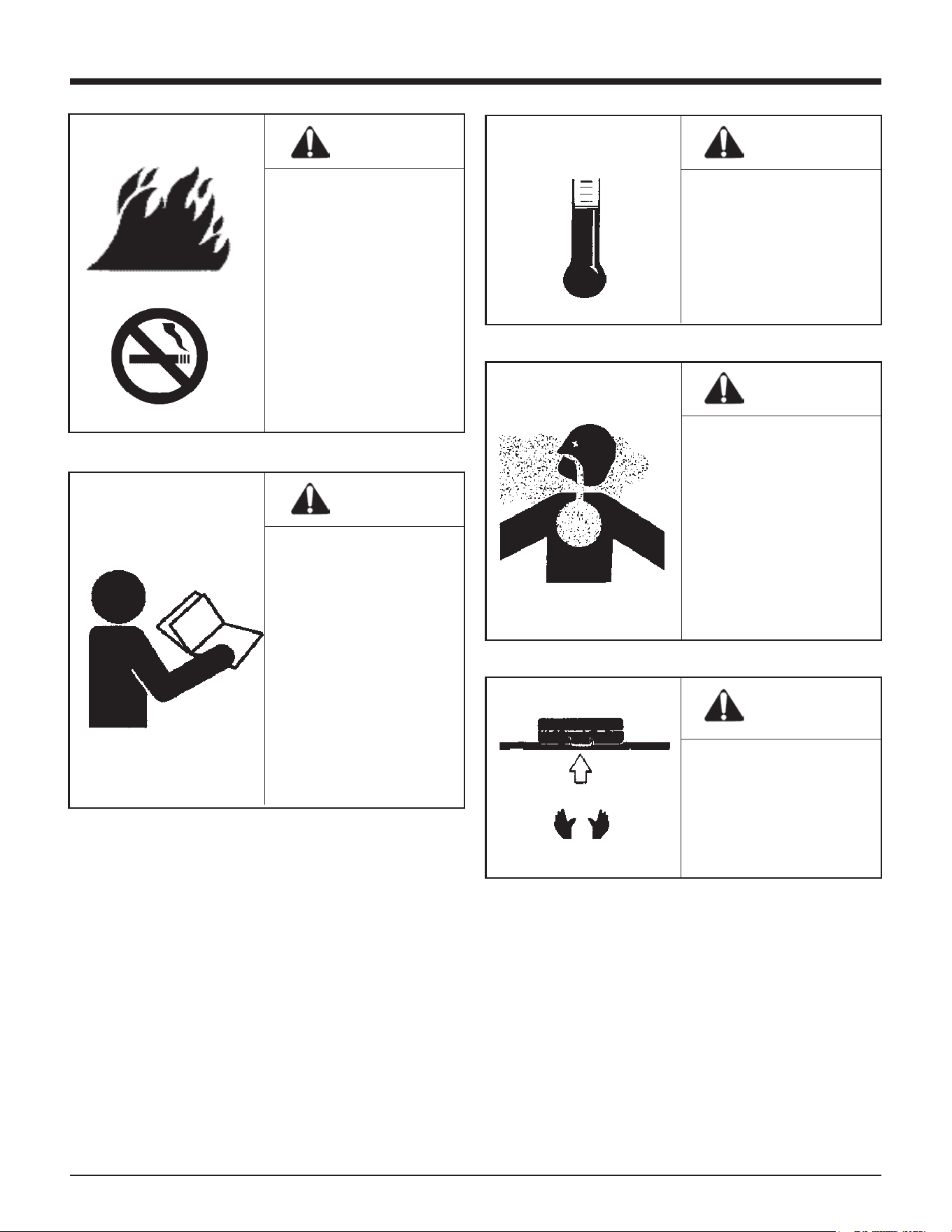
11. OPERATE THE TOOL ONLY ON THE WORK-
PIECE.
The Cordless Framing
Nailer should be operat-
ed only when it is contact
with the work surface.
When fastening thin
materials such as
plywood, be sure to
position the tool so that
the fastener is driven into
the underlying piece.
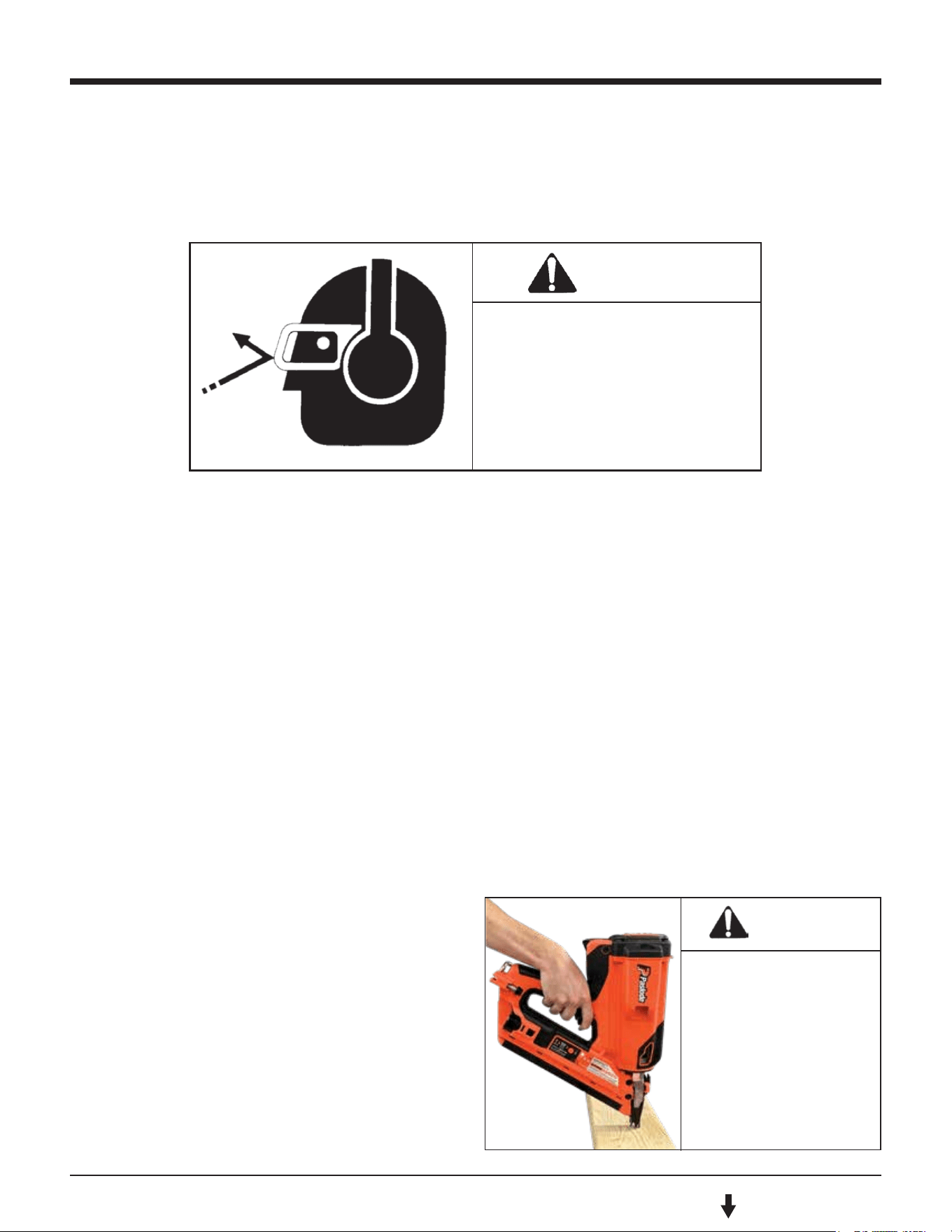
WARNING
Always wear EYE and EAR
safety gear when working
with or in the vacinity of
the Paslode Cordless
Framing Nailer.
6
Safety Instructions
WARNING
This tool must be
operated only in a
well-ventilated
environment, because
the tool exhausts carbon
monoxide similar to a
gas chainsaw or lawn-
mower. Exposure to
carbon monoxide may
cause dizziness, nausea,
or unconsciousness.
WARNING
ALWAYS keep the
Cordless Framing Nailer,
fuel cell, battery, and
battery charger out of
the reach of children.
WARNING
Do not attempt to
operate this tool until
you have read and
understood all safety
precautions and manual
instructions.
Failure to follow all
safety precautions and
instructions may result
in a permanent loss of
vision, serious personal
or even fatal injury,
property damage and/or
tool damage.
DANGER
The Cordless Framing
Nailer is an internal
combustion device. It
produces hot exhaust
gases that may ignite
flammable materials.
This tool must not be
used in a combustible
environment or in the
presence of combustible
materials, such as
flammable chemicals,
adhesives, gasoline, or
solvents.
WARNING
Do not expose the tool
to temperatures in
excess of 120ºF (49º C).
Fuel and/or the battery
may burst, releasing
flammable gas.
F C
120º 49º
7
DANGER
CHARGING SYSTEM SAFETY
INSTRUCTIONS!
IMPORTANT SAFETY INSTRUCTIONS!
SAVE THESE INSTRUCTIONS!
TO REDUCE THE RISK OF FIRE OR
ELECTRIC SHOCK, CAREFULLY
FOLLOW THESE INSTRUCTIONS
Safety Instructions
WARNING
WARNING
WARNING
WARNING
12. NEVER DRIVE FASTENERS INTO AREAS WITH
CONCEALED HAZARDS.
Always check the area behind the work surface
for electrical wiring, gas pipes, water pipes,
sewer drains, or other potential hazards.
13. ALWAYS MAINTAIN SECURE AND UNOB-
STRUCTED FOOTING WHEN ON LADDERS,
PLATFORMS, OR OTHER HIGH LOCATIONS.
15. PROPERLY STORE FUEL CELL.
16. ALWAYS STORE THE TOOL WITH THE FUEL
CELL AND BATTERY REMOVED.
Store the fuel cell in the case with the Cordless
Nailer.
17. KEEP THE TOOL CLEAN.
A clean tool is less likely to jam or malfunction.
18. KEEP YOUR HANDS CLEAR OF THE WORK
AREA SURFACE.
Battery Disposal:
The Paslode batteries contain lithium and should be
recycled or disposed of properly. It is illegal in some
areas to place a lithium battery into the trash or solid
waste stream. You may contact your local recycling
center for information on where to return the spent
battery or call 1-800-822-8837 for information on
battery recycling in your area.
For connection to a supply outside North
America, use an attachment plug adapter
of the proper configuration for the power
outlet, if needed.
14. ALLOW ONLY QUALIFIED PERSONNEL TO
OPERATE THE CORDLESS FRAMING NAILER.
Never over-reach, since
tool recoil may cause a
loss of balance. Always
be aware of edges and
drop-os when nailing
on rooftops and other
high locations. Keep
them in full view.
Always store fuel cells
where they will not be
exposed to an open
flame, sparks, or
temperatures above
120º F (49º C).
A fastener may exit at
an angle unexpectedly
and cause injury.
Only persons who have
read and fully under-
stand all tool operation,
safety, and maintenance
instructions should be
allowed to operate the
tool.
Charging Instructions
1. Remove the charger unit from the tool case and
plug it into a 120V AC outlet. Set the charger base
on a stable surface. A green light will come on to
indicate the power is on and the charger circuit is
ready.
2. Remove the battery from tool or case and insert
terminals down into the charger. The red light will
come on indicating that the battery is charging
and the green light will go out.
3. After charging is complete, the red light will go out
and the green light will come on, indicating that
the battery is fully charged. The charger will keep
the battery at full charge until it is removed.
4. Unplug the charger from the 120V AC outlet.
CHARGING TIMES:
First charge (new battery) 1.5 hours
Discharged Battery: 5 minutes to 1.5 hours
2 minute quick-
charge for 200 shots
CHARGING DON’TS:
1. Do not charge battery outdoors or in tempera-
tures above 113ºF (45ºC) or below 32ºF (0ºC).
2. Do not allow metal objects to come in contact
with the battery terminals.
3. Do not puncture or attempt to open battery case
or cells.
4. Do not store battery where it will be subjected to
temperatures above 120ºF (49ºC).
5. Do not incinerate battery.
6. Do not use a defective battery charger, one that
overheats and/or smokes when plugged in.
7. Do not immerse the battery or charger in water.
8
Battery and Charging System
NOTE
WARNING
CHEMICAL / EXPLOSION
HAZARD
Read ALL instructions
before charging or using
battery. Failure to follow
ALL instructions may result
in fire, severe burns, or
release of toxic materials,
If battery is completely discharged, the red light
and green light may alternate back and forth for
up to 20 minutes. This safety feature slowly
recharges the battery until it is ready to accept the
full charging current. If the red and green lights
continue to alternate after 20 minutes, replace
the battery.
Battery and Charging System
The Paslode Cordless tool comes with a recharge-
able Lithium Ion (Li-ion) battery and its own charging
system. This charging system is the only one that
will work with Paslode Li-ion batteries. The first
step in preparing a new tool for operation is to fully
charge the battery. New batteries are shipped
partially discharged and must be charged prior
to first use. Batteries will take 5 minutes to 1.5 hours
(time will be dependent on the amount of discharge
within the battery) to recharge.
Important Charging Notes
Battery Disposal
The Paslode batteries contain lithium and should be
re- cycled or disposed of properly.
You may contact your local recycling center for
information on where to return the spent battery or
call 1-800-822-8837 for information on Li-ion
battery recycling in your area.
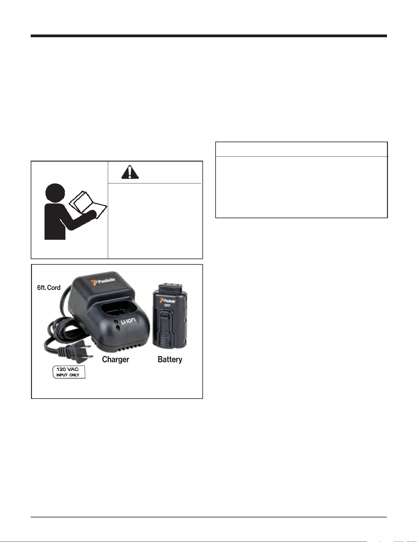
Charging System Accessories:
Battery Charger - Part No. 902667
Battery
THE PASLODE BATTERY CHARGING SYSTEM
6ft. Cord
Charger
9
Battery and Charging System
Inserting Battery
1. Load the battery, contacts first, into the Cordless
Framing Nailer.
2. Push battery fully forward into its locked position.
3. To remove battery, push down on locking tab and
slide battery out.
NOTE: If battery is left in tool for an extended period
of time in the normal operating position, the battery
will discharge completely and will require recharg-
ing.
Battery Standby
The battery can be placed in the standby position if
the tool is not going to be used for a period of time.
To place the battery into the standby position, push
down on the locking tab and slide the battery back
so that the locking tab engages into the standby
position in the handle.
Tool Actuation Modes
The tool will operate in Sequential Mode out of the
case. Every time the battery is inserted into the ON
position, the tool starts in Sequential Mode.
SEQUENTIAL MODE OPERATION
In Sequential Mode, fire the tool by first depressing
the nose against the workpiece and then pulling the
trigger for every shot.
TO ENTER RAPID FIRE MODE
Press and hold the Rapid Fire button for 3 seconds.
The blue LED will turn on. This light will switch o if
the tool is idle for 1 hour OR if the battery is removed
from the ON position.
Battery Indicator LEDs
When using the Cordless XPro Framing Nailer, the
LED lights on the handle of your tool will provide you
with important operational information.
When the battery is first installed, these 2 LEDs will
indicate your state of charge. If battery charge is
>60%, both LEDs will be green.
If battery charge is 20-60%, only this LED will be
green.
If the battery charge is <20%, this LED will be red.
When battery approaches 0%, the LED will flash
red for 90 seconds and then the tool will shut
down.
After a few seconds, the battery level indicators
will turn o and the power LED will begin to flash
green, indicating the tool is on.
Hold Rapid Fire
Button in for
3 seconds.
LED Lights Blue to
indicate Rapid Fire is ON.
TO EXIT RAPID FIRE MODE
Press and hold the Rapid Fire button for ½ second.
The blue LED will turn o. The tool will now return
to Sequential Mode.
2
STANDBY / MAINTIEN /
DE CHARGE
3
READY / PRÊT / LISTO
10
Fuel Cell
Fuel Cell
Tool Actuation Modes
The tool will operate in Sequential Mode out of the
case. Every time the battery is inserted into the ON
position, the tool starts in Sequential Mode.
SEQUENTIAL MODE OPERATION
In Sequential Mode, fire the tool by first depressing
the nose against the workpiece and then pulling the
trigger for every shot.
TO ENTER RAPID FIRE MODE
Press and hold the Rapid Fire button for 3 seconds.
The blue LED will turn on. This light will switch o if
the tool is idle for 1 hour OR if the battery is removed
from the ON position.
There is a second container inside the fuel cell. The
inner container holds the fuel. The space between
the inner container and the outer cylinder is filled
with a gas, called the propellant, which is under
pressure.
To eject the fuel, propellant pressure squeezes the
inner fuel container. This squeezing action ensures
that all the fuel is used, and that the Cordless Nailer
can operate in any position.
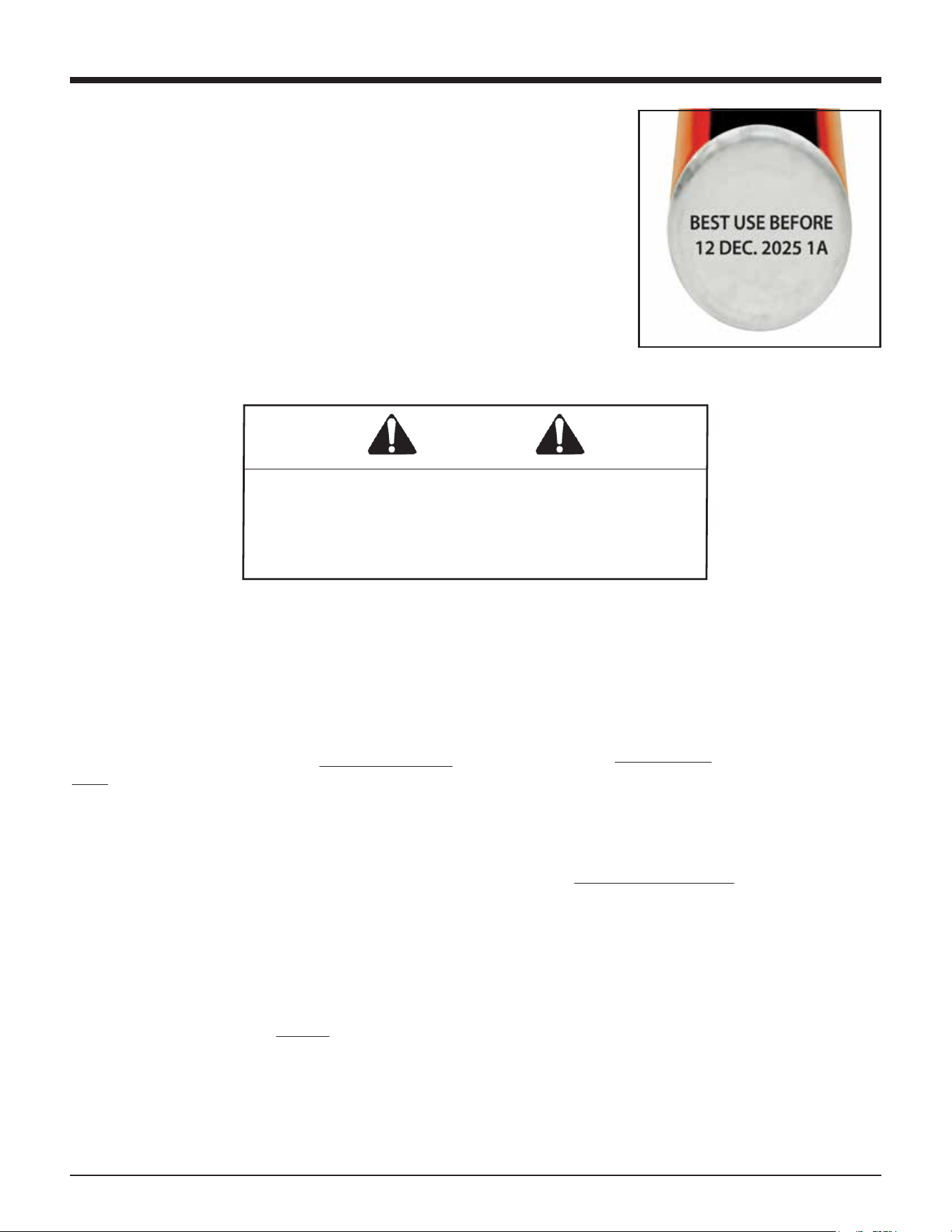
However, over time the propellant pressure dimin-
ishes until it is no longer able to squeeze the inner
fuel container. This is why a nailer using a fuel cell
beyond the “Best Use Before” date may not work
consistently or at all.
If you expose the empty fuel cell to extreme
temperatures, the propellant gas will expand and
could cause the container to burst, releasing flam-
mable gases.
The fuel contains a small amount of oil to keep the
tool lubricated during use. It is not necessary to oil
the tool during normal operation. When cleaning
the tool, use only Paslode Cordless tool oil. Using
oils not formulated for the Paslode Cordless Tool,
may cause loss of power and may damage the
internal parts of the tool's motor.
WARNING
DANGER
F C
120º 49º
EXPLOSION / FIRE
HAZARD
Read ALL safety instruc-
tions before using or
handling the fuel cartridge.
Failure to follow ALL
instructions may result in
explosion or fire. This may
cause severe personal
injuries or property
damage.
Keep the fuel cell away
from heat, sparks, and
open flame. Do not smoke
when handling or operating
tool or fuel cartridge.
Exposure to temperatures
above 120ºF (49ºC) may
cause the fuel cell to burst,
releasing flammable gas.
Sunlight can raise the inside temperature of an
unventilated car or van to above 140ºF (60ºC).
Never puncture or attempt to open the fuel cell,
it is non-refillable.
Never incinerate, reclaim, or recycle the fuel cell.
Never smoke while installing the fuel cell.
Never inhale the spray.
Keep out of the reach of children.
Store fuel cell(s) in well-ventilated areas only.
NOTE
NOTE: Altitude Restriction
1. Never attempt to refill the cell! Replace with
fresh fuel cell, and dispose of spent cell properly.
2. When replacing fuel cell also clean or replace
air filter for optimum tool operation.
Paslode Cordless technology is powered by an
internal combustion engine, which is aected by
altitude. The tool may lose power or become
erratic at elevations of 6000 feet or greater.
1. Do not attempt to remove or reuse the Paslode
Framing Fuel Cell.
2. Do not attempt to install the fuel cell cap on
other fuel cells. This may result in damage to
the tool and injury to the user and bystanders!
DANGER
11
Fuel Cell
Paslode Cordless Fuel Cells are flammable.
Do not remove fuel cartridge cap or install on
other fuel cells!
DANGER
Paslode, the industry leader in cordless technology,
provides this information to assist users with the
proper disposal of discarded fuel cells. Acceptable
disposal options vary depending on the type of fuel
cell user. All users must consider federal, state, and
local solid waste regulations to ensure that discard-
ed fuel cells are disposed of properly. Users must
contact their local solid waste authority for further
guidance.
Discarded fuel cells (used or unused) may be
considered hazardous waste under the Resource
Conservation and Recovery Act (RCRA). In general,
“household wastes” generated by homeowners and
their contractors are exempt from hazardous waste
regulation because those wastes are expressly
excluded from the definition of hazardous waste. For
example U.S. EPA has excluded as “household
waste” aerosol cans that contain residual product
and propellant. Thus under federal hazardous waste
Note:
Paslode Fuel Cells are marked with a “Best Used Before”
date on the bottom of the can.
For maximum performance use fuel before the “Best Used
Before” date.
regulations homeowners and contractors may
dispose of discarded fuel cells as general refuse in a
properly permitted municipal landfill. These users
must still contact their local solid waste authority to
determine if any state or local regulation prohibits or
restricts such disposal.
Paslode takes no responsibility for improper fuel cell
disposal. Proper disposal remains the responsibility
of sellers and users. All sellers and users must
contact their local solid waste authority to deter-
mine if any federal, state, or local regulation prohib-
its or restricts disposal. Users may obtain more
information about U.S. EPA hazardous waste regula-
tions at the following internet address: www.epa.gov
Alternatively users may contact U.S. EPA’s Toxic
Release Information Center at 1-800-424-9346 to
receive more information.
Paslode Cordless Fuel Cell Disposal Guidelines
12
CORRECT FUEL CELL LOADING PROCEDURE
To open - Push forward, lift
then back
To close - Push forward, then
down to lock fuel door
Raise fuel tube block assembly,
it will lock in up position
Load fuel cell
Carefully align fuel adaptor and
cell stem
1 2 3
4
5
Fuel Cell
13
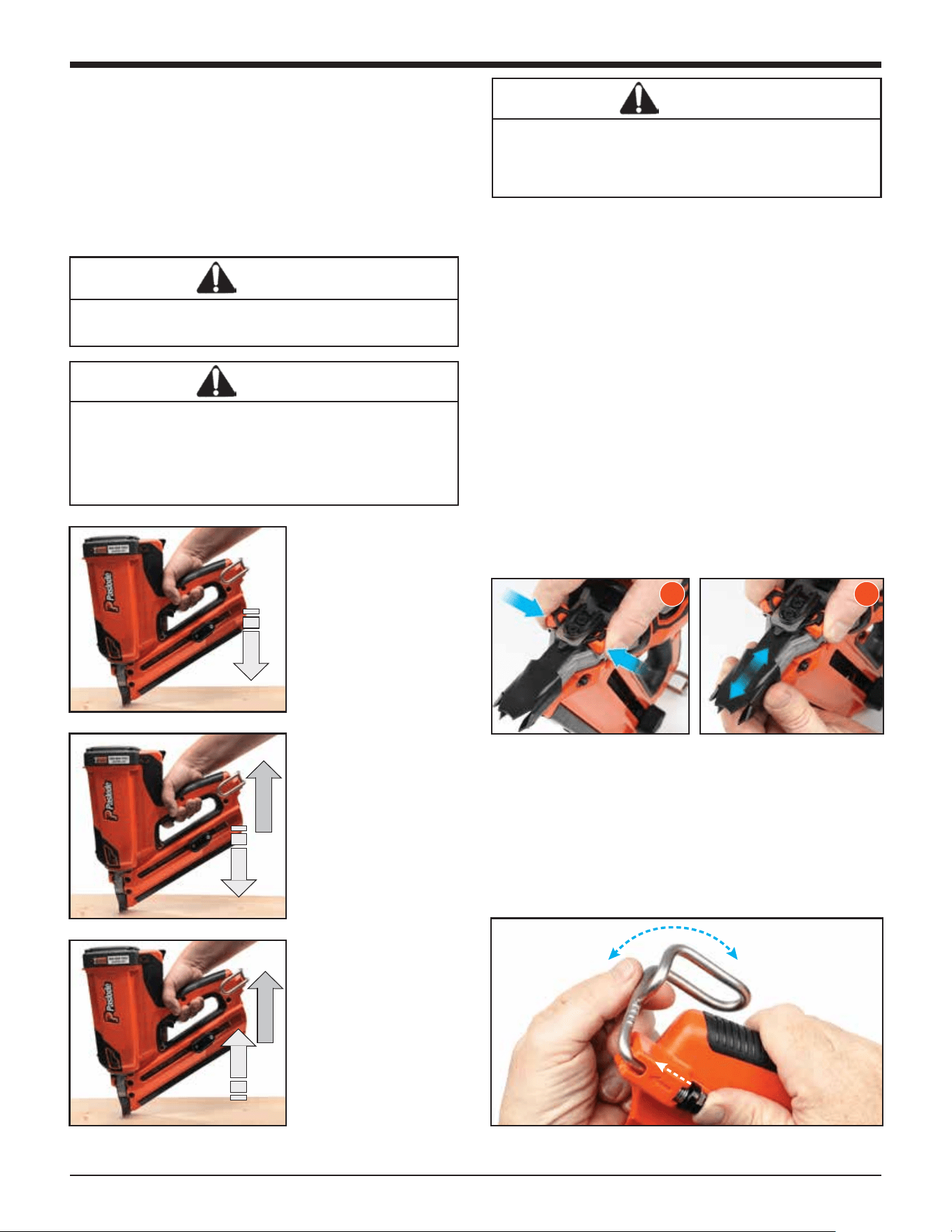
Drop the nail strip into the
empty magazine.
Pull the follower up past the
last nail. Avoid letting the follower
slam forward into the nails.
Pull the follower back slightly
and push the lever.
Position the tool upright allowing
the nail strip to drop out.
Tool is ready to fire.
Preparing the Paslode Cordless
Framing Nailer for Use
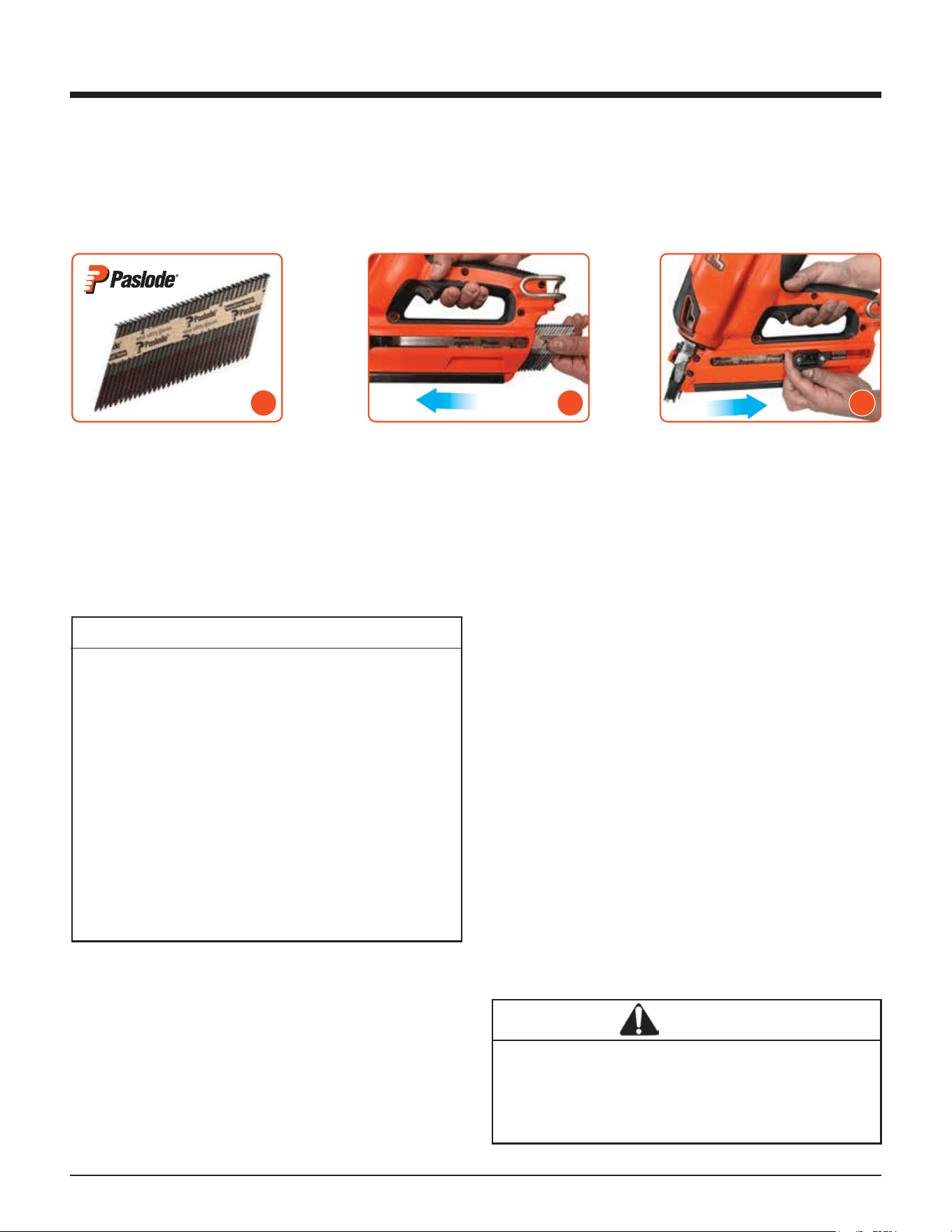
Fasteners
The Paslode Cordless Nailer drives Paslode RounDrive® and D/Head nails, which have been collated into
strips. The use of nails that do not meet Paslode standards could cause tool damage and void your warranty.
Paslode nail sizes and types are illustrated in the Fasteners and Applications section.
Hot Weather Operation
The Cordless Nailer requires cooling of the motor
assembly to work properly. The fan normally
provides the necessary air flow to permit continuous
operation. Whenever the Nailer is idle for extended
periods, keep the fuel and tool out of direct sunlight
and in surroundings where temperatures will not
exceed 120ºF (49ºC). After extended periods of
continuous use, it may be necessary to cool the
motor by setting tool aside for 10-15 minutes or until
the tool operates normally. An overheated tool may
not drive nails completely or may operate erratically.
Cold Weather Operation
Fuel at cold temperatures lose the required propel-
lant force. Bring the tool, battery, and fuel cartridge
above minimum operating temperature without
direct exposure to flame, and check the battery.
Paslode Cordless Framing Nailer and Out-
door Weather
Use the Cordless Framing Nailer outdoors, in clear
weather, when the nailer, fuel cartridge, and battery
are between 14°F (-10°C) and 120°F (49°C).
Lockout Feature
When the follower reaches the lockout area (5
nails remaining) the tool will automatically lock
to prevent it from firing. To unlock the tool,
simply reload another strip of nails.
The purpose of this feature is to prevent need-
less blank cycling, which could mar woods,
waste fuel, and damage tool components. Five
(5) nails will be left in the magazine when the
follower reaches the lockout area. When
changing fastener length or loading the tool
you should inspect the magazine and nose for
any fasteners left in the tool. These nails will not
be visible unless you open the quick-clear of
the tool.
CAUTION
The Cordless Framing Nailer should not be used in
the rain or where excessive moisture is present.
The use of the Paslode Cordless Technology
under these conditions may result in damage to
tool components and cause tool to malfunction.
Loading Fasteners
Unloading Fasteners
1 2 3
14
PRESS WORK
CONTACTING
ELEMENT AGAINST
THE WORK
SURFACE.
Fan motor starts, fuel
is injected into
combustion chamber
and mixed with air by
the fan.
SQUEEZE TRIGGER
Spark plug ignites the
fuel/air mixture,
driving the piston
assembly down on the
fastener.
RELEASE TRIGGER -
LIFT TOOL
Combustion
chamber opens.
Fan exhausts, cooling
internal components.
Note: The fan will run
for approximately 10
seconds after the last
nail is driven. After
rapid firing (at least 32
times in 80 seconds),
the fan will run for 60
seconds to cool the
tool.
Paslode Cordless Framing Nailer Operation
Hot Weather Operation
The Cordless Nailer requires cooling of the motor
assembly to work properly. The fan normally
provides the necessary air flow to permit continuous
operation. Whenever the Nailer is idle for extended
periods, keep the fuel and tool out of direct sunlight
and in surroundings where temperatures will not
exceed 120ºF (49ºC). After extended periods of
continuous use, it may be necessary to cool the
motor by setting tool aside for 10-15 minutes or until
the tool operates normally. An overheated tool may
not drive nails completely or may operate erratically.
Cold Weather Operation
Fuel at cold temperatures lose the required propel-
lant force. Bring the tool, battery, and fuel cartridge
above minimum operating temperature without
direct exposure to flame, and check the battery.
Cold Weather Operation (Continued)
It will be necessary to repeat this procedure several
times until the temperature of the tool warms up
enough to operate in its normal mode.
Once the tool reaches operational temperature the tool
will generate its own heat and will function normally.
If the tool sits for an extended period of time and cools
down it may be necessary to repeat these steps.
Depth of Drive Adjustment
Remove the battery before adjusting the
depth of drive.
The depth of drive adjustment is made by adjusting the
work contacting element. Squeezing the probe stop
release buttons toward each other will allow the work
contacting element to be moved up or down.
If the tool is over-driving (the nail head is driven below
the surface of the wood), the work contacting element
should be moved down slightly. If the nails stand up (the
head is not flush with the work surface), the work
contacting element should be moved up slightly. The
indicator marks are set at 1/10" (2.5mm) increments
with a total range of 1/2" (13mm).
Adjust the work contacting element to get the nail head
depth to meet job requirements.
Adjustable Utility Hook
The adjustable utility hook can be used as a belt or
rafter hook. To adjust the utility hook, push the black
button in the direction of the arrow and rotate it to the
desired position.
WARNING
During the warm-up process, never expose the
tool, fuel cell, or battery to flame.
DANGER
The work contacting element and nose will
become hot after prolonged or rapid use. If it
becomes necessary to adjust the work contacting
element, avoid touching with bare hands.
CAUTION
This tool must be operated in a well ventilated
environment, because the tool exhausts carbon
monoxide similar to a chainsaw or lawn mower.
Exposure to carbon monoxide may cause dizzi-
ness, nausea, or unconsciousness.
1 2
16
Fasteners and Applications
SIZE
2" x .113 (6D) (50 x 2.87 mm)
2" x .113 (6D) (50 x 2.87 mm)
TYPE
Common Ring Shank
Common ring shank,
HD Galv, GalvGuard™
APPLICATION
Underlayment, wall sheathing,
roof and floor decking, siding
Fencing, siding
2-3/8" x .113 (8D) (60 x 2.87 mm)
Cooler ring shank
HD Galv, GalvGuard™
Roof & floor decking, underlayment,
sheathing
3" x .120 (10D) (76 x 3.05 mm)
3" x .120 (10D) (76 x 3.05 mm)
Coated nail
Ring shank,
HD Galv, GalvGuard™
Remodeling
Fencing, recreational decking, siding,
tile roofs
3" x .131 (10D) (75 x 3.33 mm)
3-1/4" x .131 (12D) (82 x 3.33 mm)
Coated nail
Coated nail
Framing
Framing
Smooth Shank - For general construction, carpentry and
framing: the most popular and versatile.
Ring Shank - The ring shank provides improved withdrawal
resistance for applications where the resistance from smooth
shank fasteners is not adequate: floor decking, crating,
pallets.
Hardened Steel - For attaching wooden plates to green
concrete foundations; 2X furring strips to cinder block.
GalvGuard™- These nails are hot dipped galvanized with
a baked on polymer coating. They offer the highest cor-
rosion resistance of any galvanized nail. These nails
should be used where higher corrosion resistance is required
to retard rust and rust staining. Recommended for use in
natural wood siding, such as cedar, redwood, cypress and
preservative treated lumber. (Not for use in all-weather
wood foundations.)
The Paslode Cordless Framing Nailer is not recommended for use with 3" (75mm)
and longer Ring Shank nails in pressure trea. ted lumber
Note: For Australia and New Zealand, nail sizes, coating types and applications
15
Fasteners and Applications
Fasteners
Smooth Shank - For general construction, carpentry and framing: the most popular and versatile.
Ring Shank - The ring shank provides improved withdrawal resistance for applications where the resistance from
smooth shank fasteners is not adequate: floor decking, crating, pallets.
Hardened Steel - For attaching wooden plates to green concrete foundations; 2X furring strips to cinder block.
HDG- These nails are hot dipped galvanized with a baked on polymer coating. They oer the highest corrosion
resistance of any galvanized nail. These nails should be used where higher corrosion resistance is required to
retard rust and rust staining. Recommended for use in natural wood siding, such as cedar, redwood, cypress and
preservative treated lumber. (Not for use in all-weather wood foundations.)
The Paslode Cordless Framing Nailer is not recommended for use with 3" (75mm) and longer Ring Shank nails in
pressure treated lumber.
Note: For Australia and New Zealand, nail sizes, coating types and applications may vary.
Please check your local building code regulations.
16
Fasteners and Applications
SIZE
2" x .113 (6D) (50 x 2.87 mm)
2" x .113 (6D) (50 x 2.87 mm)
TYPE
Common Ring Shank
Common ring shank,
HD Galv, GalvGuard™
APPLICATION
Underlayment, wall sheathing,
roof and floor decking, siding
Fencing, siding
2-3/8" x .113 (8D) (60 x 2.87 mm)
Cooler ring shank
HD Galv, GalvGuard™
Roof & floor decking, underlayment,
sheathing
3" x .120 (10D) (76 x 3.05 mm)
3" x .120 (10D) (76 x 3.05 mm)
Coated nail
Ring shank,
HD Galv, GalvGuard™
Remodeling
Fencing, recreational decking, siding,
tile roofs
3" x .131 (10D) (75 x 3.33 mm)
3-1/4" x .131 (12D) (82 x 3.33 mm)
Coated nail
Coated nail
Framing
Framing
Smooth Shank - For general construction, carpentry and
framing: the most popular and versatile.
Ring Shank - The ring shank provides improved withdrawal
resistance for applications where the resistance from smooth
shank fasteners is not adequate: floor decking, crating,
pallets.
Hardened Steel - For attaching wooden plates to green
concrete foundations; 2X furring strips to cinder block.
GalvGuard™- These nails are hot dipped galvanized with
a baked on polymer coating. They offer the highest cor-
rosion resistance of any galvanized nail. These nails
should be used where higher corrosion resistance is required
to retard rust and rust staining. Recommended for use in
natural wood siding, such as cedar, redwood, cypress and
preservative treated lumber. (Not for use in all-weather
wood foundations.)
The Paslode Cordless Framing Nailer is not recommended for use with 3" (75mm)
and longer Ring Shank nails in pressure trea. ted lumber
Note: For Australia and New Zealand, nail sizes, coating types and applications
16
Servicing
Restrict Field Service to the Following
CHECKING THE CHARGE LEVEL OF THE
BATTERY
RECHARGING THE BATTERY
CHECKING THE FUEL CELL
REPLACING THE FUEL CELL
CLEANING/REPLACING THE AIR FILTER
CLEARING A JAM
CLEANING THE TOOL (See cleaning Manual)
REPLACING TIP
Attempts to go beyond these procedures could result
in serious personal injury or damage to the Cordless
Nailer and voiding the warranty.
There are certain problems you may encounter when
you are using the Cordless Nailer that you will be able to
correct on the work site. The following field service
procedures are the only service procedures you should
attempt. Anything else that may appear wrong with the
Cordless Nailer should only be diagnosed and repaired
by a fully trained service technician. If you have any
reason to believe that your problem is beyond the
service procedures in this manual, contact Paslode.
Fuel Cell Check
If the nailer’s fan operates and the light is green but the tool
will not cycle consistently or at all, check the fuel cell. First
remove the fuel cell from the tool and check the “Best Use
Before” date stamped on the bottom. If it is beyond this date,
the fuel cell may not consistently dispense the proper amount
of fuel – even if the fuel cell has never been used. To test if the
fuel cell still dispenses fuel:
1. Hold the fuel cell in the upright position with the flat bottom
toward the ground – this orientation is important for a proper
test.
2. Gently push the tip of the fuel cell cap against a solid object
five times.
3. A small amount of fuel should be released all five times.
4. If fuel is not released every time it indicates the fuel cell is
empty or expired* and must be replaced.
* Expired fuel cell may dispense fuel when upside down or
sideways but will not work more than a couple of times in the
upright position because of the reduced internal pressure
(see page 10 for more information).
Battery Check
Periodically check the battery indicator lights in the handle of
the Cordless Nailer. When encountering a problem, the first
step should always be to make sure the battery has enough
charge to operate the tool.
When you first insert the battery into the ON position, the
battery indicators in the handle will show the battery status.
While nailing, press the rapid fire button at any time for a quick
read of battery status. See Battery Indicator Lights section on
Page 9 for additional information.
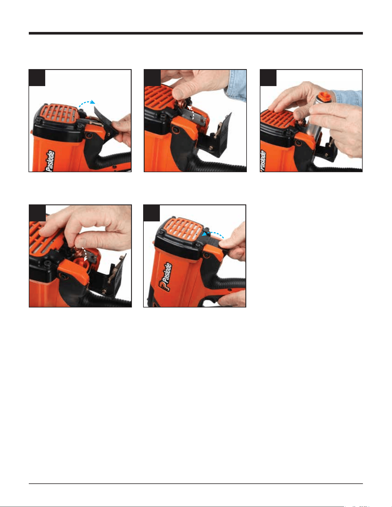
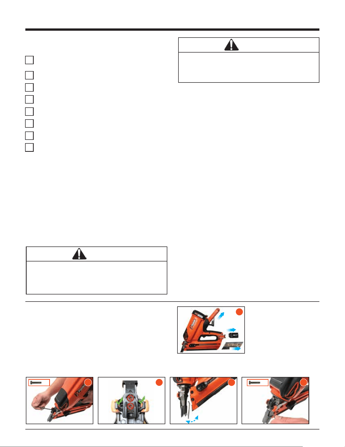
Clearing a Jam
An occasional problem you may encounter is a jammed
fastener. Because of the unique design of the Cordless
Framing Nailer, clearing a jammed fastener is easy:
DANGER
Never attempt any maintenance of a Paslode
Cordless tool without first removing the fuel cell
and battery. Maintenance should be started only
after the tool is completely inoperative.
DANGER
Wear safety glasses when performing this test.
Never perform this test near an open flame or
sparks, while smoking, or where the fuel might get
in your eyes.
Push the lever in the
follower to release the
fasteners.
Loosen the (2) magazine
mounting screws with
the 5/32 hex key.
Pull handle/magazine
away from the nose of
the tool and clear jam.
Realign handle
magazine to nose, and
tighten mounting screws.
Remove the Paslode Framing
Fuel Cell and battery.
3
3
1
2
x2
4 5
x2
16
Fasteners and Applications
SIZE
2" x .113 (6D) (50 x 2.87 mm)
2" x .113 (6D) (50 x 2.87 mm)
TYPE
Common Ring Shank
Common ring shank,
HD Galv, GalvGuard™
APPLICATION
Underlayment, wall sheathing,
roof and floor decking, siding
Fencing, siding
2-3/8" x .113 (8D) (60 x 2.87 mm)
Cooler ring shank
HD Galv, GalvGuard™
Roof & floor decking, underlayment,
sheathing
3" x .120 (10D) (76 x 3.05 mm)
3" x .120 (10D) (76 x 3.05 mm)
Coated nail
Ring shank,
HD Galv, GalvGuard™
Remodeling
Fencing, recreational decking, siding,
tile roofs
3" x .131 (10D) (75 x 3.33 mm)
3-1/4" x .131 (12D) (82 x 3.33 mm)
Coated nail
Coated nail
Framing
Framing
Smooth Shank - For general construction, carpentry and
framing: the most popular and versatile.
Ring Shank - The ring shank provides improved withdrawal
resistance for applications where the resistance from smooth
shank fasteners is not adequate: floor decking, crating,
pallets.
Hardened Steel - For attaching wooden plates to green
concrete foundations; 2X furring strips to cinder block.
GalvGuard™- These nails are hot dipped galvanized with
a baked on polymer coating. They offer the highest cor-
rosion resistance of any galvanized nail. These nails
should be used where higher corrosion resistance is required
to retard rust and rust staining. Recommended for use in
natural wood siding, such as cedar, redwood, cypress and
preservative treated lumber. (Not for use in all-weather
wood foundations.)
The Paslode Cordless Framing Nailer is not recommended for use with 3" (75mm)
and longer Ring Shank nails in pressure trea. ted lumber
Note: For Australia and New Zealand, nail sizes, coating types and applications
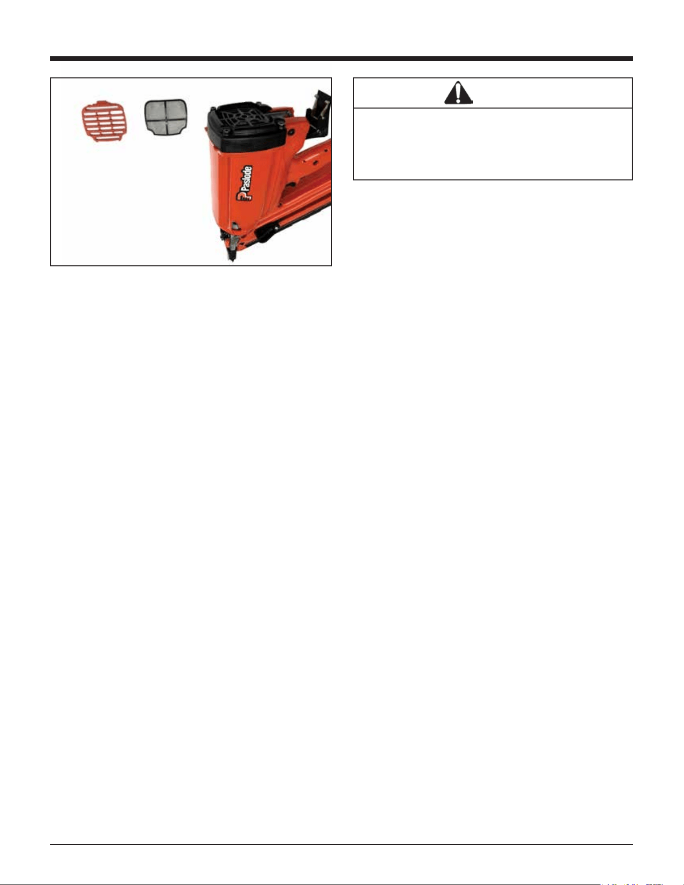
Cleaning the Air Filter
Open the grille by pressing slightly above the adapter,
and pivoting the cover open. The air filter simply lifts
out.
Tap the filter GENTLY to remove any dust. Check and
clean the air filter every two days. Soap and water
restores the filter to a "like new" condition.
Tool Cleaning and Oiling
Periodic cleaning and oiling are necessary to keep the
Paslode Cordless Nailer operating properly. The tool
should be cleaned and lubricated at least every
50,000 cycles. This number may vary depending upon
the rate at which the tool is used and the operating
conditions it is used in. The chart in the cleaning
instructions will help you determine how often the tool
should be cleaned.
17
Servicing
End-of-Workday Routine
At the end of each workday, conduct an end-of-work-
day routine.
These simple steps are based on maintaining the
safety and operational eciency of the Cordless Nailer.
Before you leave the work site:
1. Remove battery and store in tool case. Always use
the Cordless Nailer Case for transporting and storing
the tool.
2. Dispose of all empty fuel cells (see page 11).
Remember to dispose of fuel cells where they will not
be crushed, punctured, burned, or found by children.
When you get home:
1. Place the battery in its charger if it needs charging as
indicated by the red charge light on the handle.
2. Wipe your Cordless Nailer with a clean, soft cloth.
3. Remove and clean the filter if needed.
4. Check the Probe to ensure it is operating freely.
Cordless Framing Nailer Paslode Cordless
Tool Accessories
A variety of accessories are available for the
Paslode Cordless Framing Nailer:
No-Mar Work Contacting Element
USA Part No. 901252
Battery
USA Part No. 902654
Clear Safety Glasses
USA Part No. 401382
Paslode Lubricating Oil
USA Part No. 401482
Battery Charger
USA Part No. 902667
Paslode Cordless Framing Nailer Case
USA Part No. 905607
Contact your Paslode® representative for additional
information.
Tools
A 5/32 Hex Socket Wrench (Part No. 401331) is
provided with each Paslode Cordless framer.
WARNING
Make certain magazine mounting screws are
tight and magazine is tight to nose. Attempting
to fire tool with a loose magazine will result in
loss of nail control, damage to tool, or nail
discharge toward operator.
Grille Filter
18
Troubleshooting
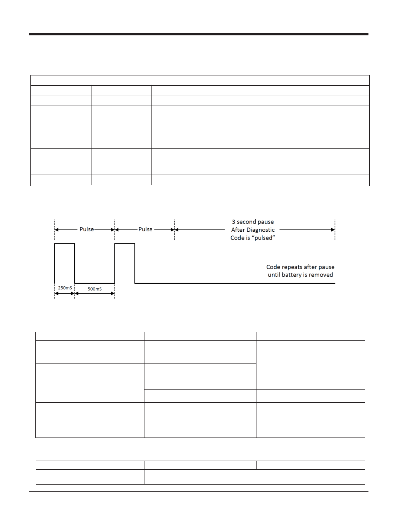
LED Diagnostic Codes
The LED above the low battery icon will flash if the tool is having any of the below errors.
Error Code Diagnostics Table
Number of Flashes
Error
1
Fan Short
2
Magnet Short
3
Fan Open / Stall
4
Magnet Open
5
Bumpfire LED(1)
6
Bumpfire Switch(1)
7
Ignition
Each flash will be ON 250mS followed by OFF 500mS. After the diagnostic code flash(es) there is a 3 second
OFF pause. Then the diagnostic flash(es) repeat.
Preparing Tool for Operation - Battery/Charger Problems
SYMPTOM
POSSIBLE PROBLEMS
SERVICE
Battery does not appear to accept charge
when the battery and charger are plugged
into the wall mount adapter.
Inoperative indicator lights on charger, or
defective charger.
Try battery in tool after a full charge cycle. If
tool LED is green, charger is not working
properly. Replace charger, or monitor
charging time to ensure battery has
adequate time for recharging. It is normal
for battery to feel warm after properly
charging.
Battery charger flashes red/green for more
than 20 minutes.
Defective battery.
Battery damaged or cycle life exhausted.
Replace battery.
Charger gets hot, makes excessively loud
noise, or smokes during charging cycle.
Charger cord or wall plug gets hot.
Damaged charger.
Discontinue use immediately and unplug
from power source. Replace charger and
tag or dispose of charger to prevent
accidental reuse or connection to power
source.
Normal Stage of Operation
SYMPTOM
POSSIBLE PROBLEMS
SERVICE
Fan does not run
Refer to Error Codes Diagnostics Table
18
Troubleshooting
LED Diagnostic Codes
The LED above the low battery icon will flash if the tool is having any of the below errors.
Error Code Diagnostics Table
Number of Flashes
Error
1
Fan Short
2
Magnet Short
3
Fan Open / Stall
4
Magnet Open
5
Bumpfire LED(1)
6
Bumpfire Switch(1)
7
Ignition
Each flash will be ON 250mS followed by OFF 500mS. After the diagnostic code flash(es) there is a 3 second
OFF pause. Then the diagnostic flash(es) repeat.
Preparing Tool for Operation - Battery/Charger Problems
SYMPTOM
POSSIBLE PROBLEMS
SERVICE
Battery does not appear to accept charge
when the battery and charger are plugged
into the wall mount adapter.
Inoperative indicator lights on charger, or
defective charger.
Try battery in tool after a full charge cycle. If
tool LED is green, charger is not working
properly. Replace charger, or monitor
charging time to ensure battery has
adequate time for recharging. It is normal
for battery to feel warm after properly
charging.
Battery charger flashes red/green for more
than 20 minutes.
Defective battery.
Battery damaged or cycle life exhausted.
Replace battery.
Charger gets hot, makes excessively loud
noise, or smokes during charging cycle.
Charger cord or wall plug gets hot.
Damaged charger.
Discontinue use immediately and unplug
from power source. Replace charger and
tag or dispose of charger to prevent
accidental reuse or connection to power
source.
Normal Stage of Operation
SYMPTOM
POSSIBLE PROBLEMS
SERVICE
Fan does not run
Refer to Error Codes Diagnostics Table
18
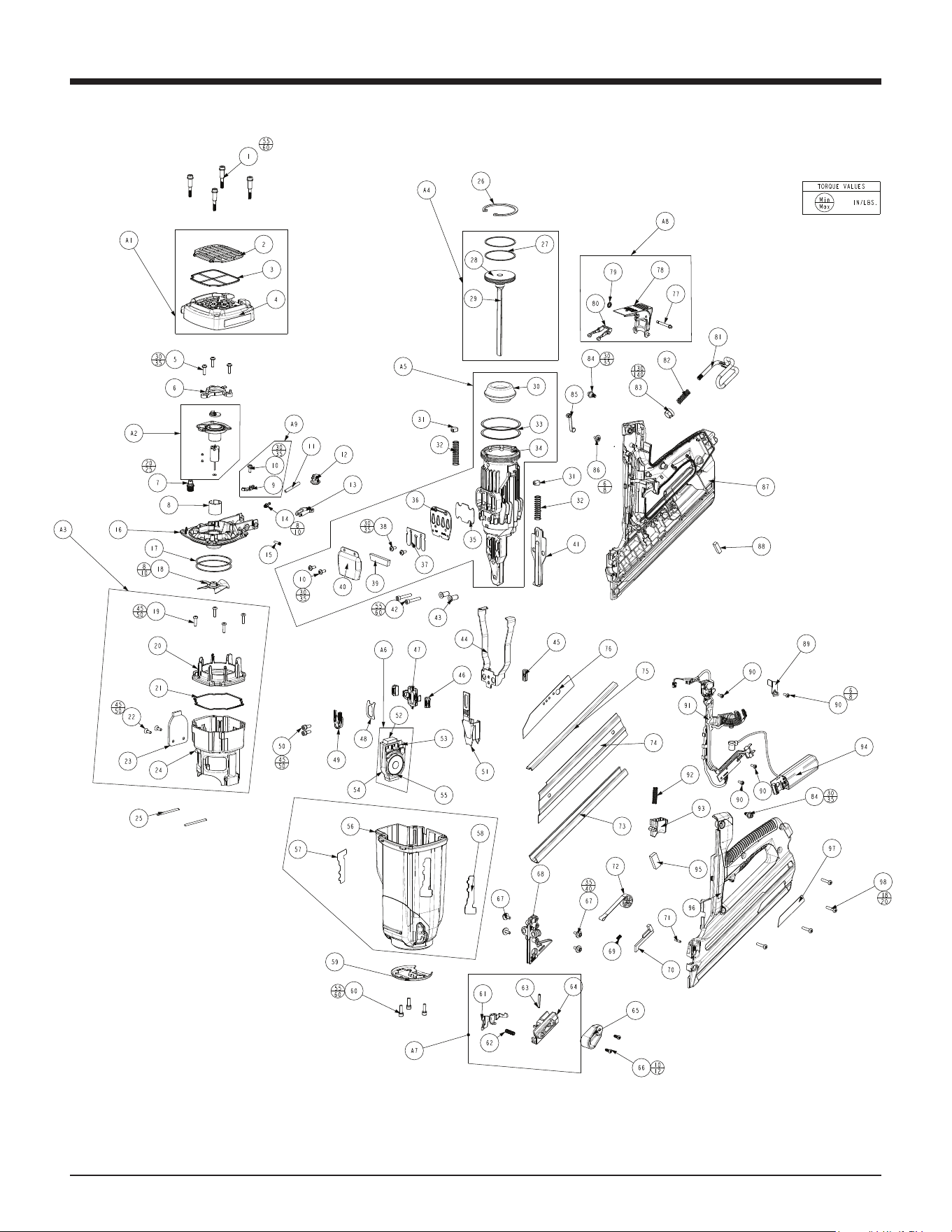
Tool Schematic
Parts Legend CF325XPRO24 CORDLESS XPRO 30º FRAMING NAILER 906800; 906800DHL
1 901063 Shoulder Screw 4
2 906305 Grille 1
3 900315 Filter 1
4 906805 XPRO Cap 1
5 900902 Screw, SEMS, 8-32 x 5/8 Thread Forming 3
6 902637 Travel Limiter 1
7 900286 Spark Plug Assembly, Includes O-Ring 1
8 401356 Motor Sleeve 1
9 906817 Clip, Cylinder Head 1
10 900596 Screw, SEMS, 8-32 x 7/16 Thread Forming 3
11 904546 Fuel Tube 1
12 905606 Fuel Block 1
13 902211 Fuel Pivot Arm 1
14 904517 Fuel Barb 1
15 902213 Pivot Arm Pin 1
16 906816 Framing Cylinder Head 1
17 900935 Ring Seal (Cylinder Head) 2
18 403167 Fan Assembly 1
19 900969 Screw, Thread Forming, 8-32 x 5/8 1
20 906339 Combustion Chamber Ring 1
21 900481 Seal, Combustion Chamber 1
22 906814 Flat Head Screw 8-32 x 0.5 T20 2
23 906812 Plate, Combustion Chamber 1
24 906811 XPRO Combustion Chamber 1
25 404827 Pin (CT) 2
26 401328 Retaining Ring, Bowed 1
27 401461 Ring/Piston (IM325/CT) 2
28 404421 Piston (CT) 1
29 404420 Driver Blade (CT) 1
30 905601 Bumper 1
31 404464 Stop/Rubber (CT) 2
32 404411 Spring/Chamb Return 2
33 900934 Seal Ring (CT) 2
34 906602 Sleeve 1
35 404426 Exhaust Bae 2
36 404425 Reed Plate 1
37 404424 Valve/Reed (CT) 1
38 900595 Screw, SEMS, 8-32 x 3/8 Thread Forming 2
39 404422 Muer (CT) 1
40 404423 Cover/Muer (CT) 1
41 902249 Wear Plate, Nose 1
42 403816 Screw/SHC (CT) 2
43 404445 Bushing/Shear Block (CT) 2
44 901249 Upper Probe 1
45 401380 Bar/Tie (IM325CT) 1
46 902620 Button-Probe Release 2
47 902619 Probe Release 1
48 901238 Flat Spring (CT) 1
49 901241 Probe Stop (CT) 1
50 900592 Screw, SEMS SHCS 10-32 x 1/2 2
51 906863 Lower Probe 1
52 906859 Foam Pad 2
53 906823 Grommet 1
54 906821 Magnet Cartridge 1
55 906822 Magnet Assembly 1
56 906801 XPRO Housing 1
57 918919 Paslode Logo 1
58 906311 Paslode Label 1
59 906858 Retaining Ring Mod 1
60 900593 Screw, SEMS SHCS 10-24 x 5/8 3
61 906606 XPRO Nail Claw 1
62 502020 Compression Spring .240 x .813 1
63 906337 Bypass Follower Roll Pin 1
64 906607 Follower Body, Unit B 1
65 906605 Follower Body, Unit A 1
66 337600 Follower Screw 2
67 900594 Screw, SEMS, 8-32 x 1/2 4
68 906615 Shearblock, US 1
69 404457 Spring/Switch CT 1
70 404451 Bar/Follower Lockout (CT) 1
71 906612 Spring Retention Pin 1
72 906608 Assembly, Pin Drum and Spring 1
73 902220 Channel Magazine 1
74 404441 Plate/Cover-Mag (CT) 1
75 906619 Wear Channel 1
76 906848 Warning/BF Label 1
77 902230 Pin, Fuel Door 1
78 902209 Fuel Door Actuator 1
79 902235 TX-15 Ring 1
80 902210 Dosing Lever 1
81 902237 Utility Hook 1
82 902238 Spring-Utility Hook 1
83 902227 Utility Hook Button 2
84 901222 Shoulder Screw (CT) 2
85 404448 Roller Lever Assembly 1
86 900597
Screw, SEMS, #6-19 x 3/8 48 Thd. Forming
1
87 906803 XPRO Right Handle 1
88 902621 Foam Pad / Battery 1
89 906829 XPRO Clip, MSU Wire 1
90 404702 Screw / Thread Form 4
91 906835 MCB BFSW Assembly 1
92 404927 Spring / Trigger (CT) 1
93 404435 Trigger (CT) 1
94 906825 XPRO MSU Assembly 1
95 401450 Foam Pad / Connector MSU 1
96 906802 XPRO Left Handle 1
97 906853 Label, Nameplate (US) 1
98 900453 Screw, #8-16 x 7/8 48-2 Plastite 4
SUB-ASSEMBLIES
A1 906804 Assembly, XPRO Cap 1
A2 902635 Assembly, Fan Motor 1
A3 906810 Assembly, Combustion Chamber 1
A4 404485 Assembly, Driver Blade 1
A5 906603 Assembly, Sleeve 1
A6 906820 Assembly, Magnet Cartridge 1
A7 906604 Assembly, Follower 1
A8 902295 Assembly, Fuel Door 1
A9 906818 Assembly, Cyl Head Wire Clip 1
A10 906865 Assembly, Housing with Labels 1
WARNING
Always wear EYE and EAR
safety gear when working
with or in the vacinity of
the Paslode Cordless
18GA Straight Brad Finish
Nailer.
19
Tool Schematic
155 HARLEM AVE, GLENVIEW, IL
®
$Q,7:&RPSDQ\
3DVORGH
20
Troubleshooting
20
Troubleshooting
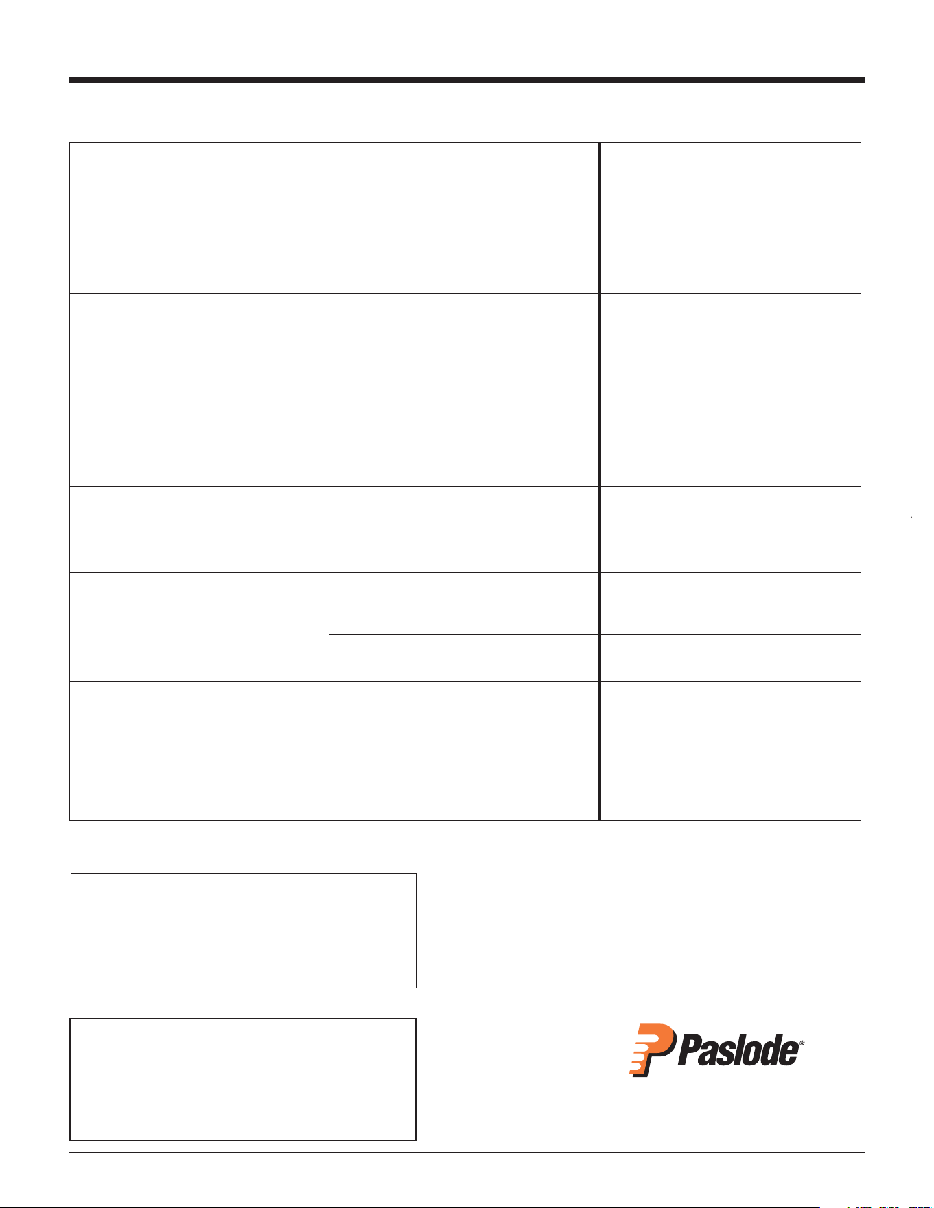
Normal Stage of Operation
SYMPTOM
POSSIBLE PROBLEMS
SERVICE
Tool operates properly, but fasteners do not
drive fully.
Work-contacting element requires adjustment.
Adjust work contacting element.
Dirty air filter.
Clean filter.
There may be loss of seal in combustion
chamber.
Press work contacting element against
workpiece for 20 seconds. Pull trigger. If
fastener does not drive, there is a leak that
requires service.
Tool operates, but no fastener is driven.
Wrong fasteners being used.
Use only fasteners meeting Paslode
®
specifications. Check Fasteners and
Applications section for fastener types and
sizes recommended for use in Cordless tool.
Tool requires cleaning.
Follow Paslode Cordless Framing Nailer
Cleaning Instructions.
Follower not properly engaged behind fastener
strip.
Position follower behind fastener strip and
engage strip.
Jammed fastener.
Clear jam.
Tool operates erratically or appears to be
losing power - tool indicator light is green.
Spark plug wire is loose.
Check spark plug wire.
Filter element is dirty, causing tool to overheat.
Remove filter element and clean. Use soap
and water to remove stubborn debris.
Tool operated and drove fasteners, but
driver blade did not return to up position.
Built-up dirt and debris on driver blade or in
nose bore.
Clean driver blade and nose bore with
degreaser cleaner.
Mid check is dirty or disabled.
Return tool to authorized Paslode
®
Cordless
dealer for service.
Combustion chamber does not drop after
tool cycles.
Work-contacting element is bent or is dirty.
Clean or replace work-contacting element.
For US Region Only
If you need further assistance, please visit:
paslode.com/service-retail-locator
to find your closest service center.
Error Code Diagnostics Table
Number of Flashes Error Service
1 Fan Short Fan wire pinched or MCB wire pinched in handle.
2 Magnet Short Magnet wire pinched with cap or wire clip.
3 Fan Open / Stall Broken or pinched fan wire or dead motor. Purple wire harness of MCB
disconnected or broken.
4 Magnet Open Magnet assembly disconnected. Green or yellow wire disconnected
from MCB. Internal magnet cartridge failure.
5 Bumpfire LED (1) Rare. Check if fan turns on when installing battery. If so, check roller lever
for debris. Otherwise, replace MCB. If problem persists, replace MSU.
6 Bumpfire Switch (1) Rare. Replace bump fire circuit board of MCB.
7 Ignition Rare. Take battery out and reinstall. If persists - contact Paslode service center.
Each flash will be ON 250mS followed by OFF 500mS. After the diagnostic code flash(es) there is a 3 second OFF pause.
Then the diagnostic flash(es) repeat.
18
Troubleshooting
LED Diagnostic Codes
The LED above the low battery icon will flash if the tool is having any of the below errors.
Error Code Diagnostics Table
Number of Flashes
Error
1
Fan Short
2
Magnet Short
3
Fan Open / Stall
4
Magnet Open
5
Bumpfire LED(1)
6
Bumpfire Switch(1)
7
Ignition
Each flash will be ON 250mS followed by OFF 500mS. After the diagnostic code flash(es) there is a 3 second
OFF pause. Then the diagnostic flash(es) repeat.
Preparing Tool for Operation - Battery/Charger Problems
SYMPTOM
POSSIBLE PROBLEMS
SERVICE
Battery does not appear to accept charge
when the battery and charger are plugged
into the wall mount adapter.
Inoperative indicator lights on charger, or
defective charger.
Try battery in tool after a full charge cycle. If
tool LED is green, charger is not working
properly. Replace charger, or monitor
charging time to ensure battery has
adequate time for recharging. It is normal
for battery to feel warm after properly
charging.
Battery charger flashes red/green for more
than 20 minutes.
Defective battery.
Battery damaged or cycle life exhausted.
Replace battery.
Charger gets hot, makes excessively loud
noise, or smokes during charging cycle.
Charger cord or wall plug gets hot.
Damaged charger.
Discontinue use immediately and unplug
from power source. Replace charger and
tag or dispose of charger to prevent
accidental reuse or connection to power
source.
Normal Stage of Operation
SYMPTOM
POSSIBLE PROBLEMS
SERVICE
Fan does not run
Refer to Error Codes Diagnostics Table
18
21
For technical support call:
1-800-222-6990
or email:
An Illinois Tool Works Company
155 Harlem Avenue
Glenview, IL 60025
www.paslode.com
Troubleshooting
20
Troubleshooting
Normal Stage of Operation
SYMPTOM
POSSIBLE PROBLEMS
SERVICE
Tool operates properly, but fasteners do not
drive fully.
Work-contacting element requires adjustment. Adjust work contacting element.
Dirty air filter. Clean filter.
There may be loss of seal in combustion
chamber.
Press work contacting element against
workpiece for 20 seconds. Pull trigger. If
fastener does not drive, there is a leak that
requires service.
Tool operates, but no fastener is driven.
Wrong fasteners being used. Use only fasteners meeting Paslode
®
specifications. Check Fasteners and
Applications section for fastener types and
sizes recommended for use in Cordless tool.
Tool requires cleaning. Follow Paslode Cordless Framing Nailer
Cleaning Instructions.
Follower not properly engaged behind fastener
strip.
Position follower behind fastener strip and
engage strip.
Jammed fastener. Clear jam.
Tool operates erratically or appears to be
losing power - tool indicator light is green.
Spark plug wire is loose.
Check spark plug wire.
Filter element is dirty, causing tool to overheat.
Remove filter element and clean. Use soap
and water to remove stubborn debris.
Tool operated and drove fasteners, but
driver blade did not return to up position.
Built-up dirt and debris on driver blade or in
nose bore.
Clean driver blade and nose bore with
degreaser cleaner.
Mid check is dirty or disabled.
Return tool to authorized Paslode
®
Cordless
dealer for service.
Combustion chamber does not drop after
tool cycles.
Work-contacting element is bent or is dirty.
Clean or replace work-contacting element.
For US Region Only
If you need further assistance, please visit:
paslode.com/service-retail-locator
to find your closest service center.
18
Troubleshooting
LED Diagnostic Codes
The LED above the low battery icon will flash if the tool is having any of the below errors.
Error Code Diagnostics Table
Number of Flashes
Error
1
Fan Short
2
Magnet Short
3
Fan Open / Stall
4
Magnet Open
5
Bumpfire LED(1)
6
Bumpfire Switch(1)
7
Ignition
Each flash will be ON 250mS followed by OFF 500mS. After the diagnostic code flash(es) there is a 3 second
OFF pause. Then the diagnostic flash(es) repeat.
Preparing Tool for Operation - Battery/Charger Problems
SYMPTOM
POSSIBLE PROBLEMS
SERVICE
Battery does not appear to accept charge
when the battery and charger are plugged
into the wall mount adapter.
Inoperative indicator lights on charger, or
defective charger.
Try battery in tool after a full charge cycle. If
tool LED is green, charger is not working
properly. Replace charger, or monitor
charging time to ensure battery has
adequate time for recharging. It is normal
for battery to feel warm after properly
charging.
Battery charger flashes red/green for more
than 20 minutes.
Defective battery.
Battery damaged or cycle life exhausted.
Replace battery.
Charger gets hot, makes excessively loud
noise, or smokes during charging cycle.
Charger cord or wall plug gets hot.
Damaged charger.
Discontinue use immediately and unplug
from power source. Replace charger and
tag or dispose of charger to prevent
accidental reuse or connection to power
source.
Normal Stage of Operation
SYMPTOM
POSSIBLE PROBLEMS
SERVICE
Fan does not run
Refer to Error Codes Diagnostics Table
18
Troubleshooting
LED Diagnostic Codes
The LED above the low battery icon will flash if the tool is having any of the below errors.
Error Code Diagnostics Table
Number of Flashes
Error
1
Fan Short
2
Magnet Short
3
Fan Open / Stall
4
Magnet Open
5
Bumpfire LED(1)
6
Bumpfire Switch(1)
7
Ignition
Each flash will be ON 250mS followed by OFF 500mS. After the diagnostic code flash(es) there is a 3 second
OFF pause. Then the diagnostic flash(es) repeat.
Preparing Tool for Operation - Battery/Charger Problems
SYMPTOM
POSSIBLE PROBLEMS
SERVICE
Battery does not appear to accept charge
when the battery and charger are plugged
into the wall mount adapter.
Inoperative indicator lights on charger, or
defective charger.
Try battery in tool after a full charge cycle. If
tool LED is green, charger is not working
properly. Replace charger, or monitor
charging time to ensure battery has
adequate time for recharging. It is normal
for battery to feel warm after properly
charging.
Battery charger flashes red/green for more
than 20 minutes.
Defective battery.
Battery damaged or cycle life exhausted.
Replace battery.
Charger gets hot, makes excessively loud
noise, or smokes during charging cycle.
Charger cord or wall plug gets hot.
Damaged charger.
Discontinue use immediately and unplug
from power source. Replace charger and
tag or dispose of charger to prevent
accidental reuse or connection to power
source.
Normal Stage of Operation
SYMPTOM
POSSIBLE PROBLEMS
SERVICE
Fan does not run
Refer to Error Codes Diagnostics Table
An Illinois Tool Works Company
155 Harlem Avenue
Glenview, IL 60025
www.paslode.com
19
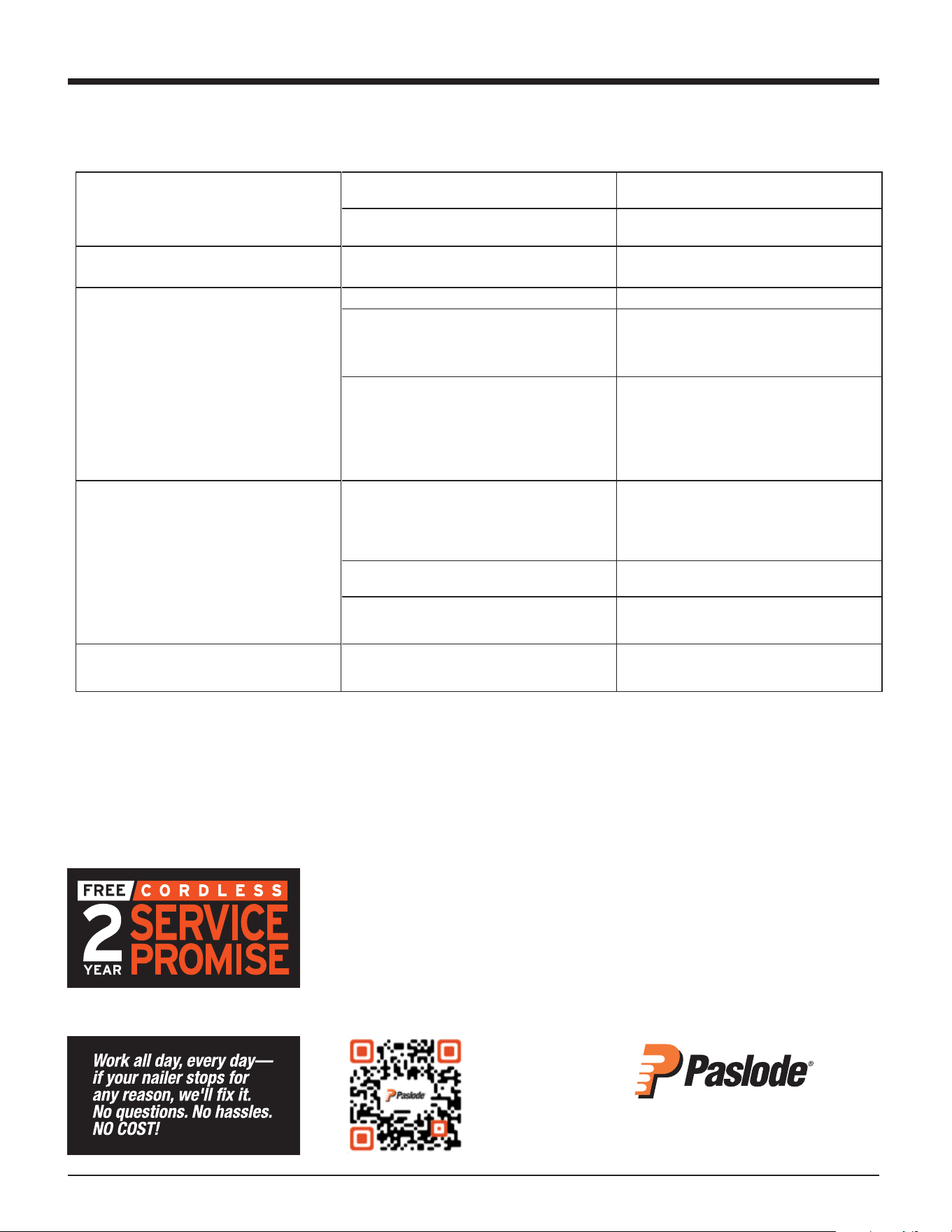
Battery is not charged. Charge battery.
Battery terminals are oily, dirty, or corroded.
Clean battery terminals with cloth or pencil
eraser.
Fan does not run, or runs slower than
normal
Battery is discharged.
Charge battery.
Work-contacting element does not depress
fully - tool does not operate.
Four (4) or less nails in tool. Load strip of nails.
Lockout bracket is stuck in lockout position.
Check lockout.
If the lockout is stuck or not working properly,
stop using the tool and return to an authorized
Paslode dealer for service.
Work-contacting element is bent, worn or at
the deepest setting.
Follower
is
not
behind
fasteners.
Remove and inspect lower probe. Clean,
adjust or replace lower probe as required.
Position
follower
behind
fasteners.
Tool will not cycle - fan runs, LED 1
is solid
green.
Paslode Framing Fuel Cell empty or past the
“Best Use Before” date stamped on the bottom
of the fuel cell.
Replace Paslode Framing Fuel Cell. See page
16 for details on how to check fuel cells.
Spark
plug
is
dirty.
Clean
tool
cylinder
head
and
spark
plug.
No spark is generated.
Return tool to authorized Paslode
®
dealer for
service.
Tool blank fires – combustion occurs but
no nail comes out of the tool
Dirty or sticky sleeve bore.
Follow Paslode Cordless Framing Nailer
Cleaning Instructions.
If tool will not operate after following the above service directions, return the tool to an authorized Paslode
®
representative for service.
18
22
Troubleshooting
Still not working? Here are more options:
• Your nailer may qualify for our Cordless 2 Year Service Promise. Visit
paslode.com for more information, or call us at 1-800-222-6990.
• Keep you Cordless Nailer in top form. Visit paslode.com and watch
our Cleaning and Maintenance videos
20
Troubleshooting
Normal Stage of Operation
SYMPTOM
POSSIBLE PROBLEMS
SERVICE
Tool operates properly, but fasteners do not
drive fully.
Work-contacting element requires adjustment.
Adjust work contacting element.
Dirty air filter.
Clean filter.
There may be loss of seal in combustion
chamber.
Press work contacting element against
workpiece for 20 seconds. Pull trigger. If
fastener does not drive, there is a leak that
requires service.
Tool operates, but no fastener is driven.
Wrong fasteners being used.
Use only fasteners meeting Paslode
®
specifications. Check Fasteners and
Applications section for fastener types and
sizes recommended for use in Cordless tool.
Tool requires cleaning.
Follow Paslode Cordless Framing Nailer
Cleaning Instructions.
Follower not properly engaged behind fastener
strip.
Position follower behind fastener strip and
engage strip.
Jammed fastener.
Clear jam.
Tool operates erratically or appears to be
losing power - tool indicator light is green.
Spark plug wire is loose.
Check spark plug wire.
Filter element is dirty, causing tool to overheat.
Remove filter element and clean. Use soap
and water to remove stubborn debris.
Tool operated and drove fasteners, but
driver blade did not return to up position.
Built-up dirt and debris on driver blade or in
nose bore.
Clean driver blade and nose bore with
degreaser cleaner.
Mid check is dirty or disabled.
Return tool to authorized Paslode
®
Cordless
dealer for service.
Combustion chamber does not drop after
tool cycles.
Work-contacting element is bent or is dirty.
Clean or replace work-contacting element.
For US Region Only
If you need further assistance, please visit:
paslode.com/service-retail-locator
to find your closest service center.
18
Troubleshooting
LED Diagnostic Codes
The LED above the low battery icon will flash if the tool is having any of the below errors.
Error Code Diagnostics Table
Number of Flashes
Error
1
Fan Short
2
Magnet Short
3
Fan Open / Stall
4
Magnet Open
5
Bumpfire LED(1)
6
Bumpfire Switch(1)
7
Ignition
Each flash will be ON 250mS followed by OFF 500mS. After the diagnostic code flash(es) there is a 3 second
OFF pause. Then the diagnostic flash(es) repeat.
Preparing Tool for Operation - Battery/Charger Problems
SYMPTOM
POSSIBLE PROBLEMS
SERVICE
Battery does not appear to accept charge
when the battery and charger are plugged
into the wall mount adapter.
Inoperative indicator lights on charger, or
defective charger.
Try battery in tool after a full charge cycle. If
tool LED is green, charger is not working
properly. Replace charger, or monitor
charging time to ensure battery has
adequate time for recharging. It is normal
for battery to feel warm after properly
charging.
Battery charger flashes red/green for more
than 20 minutes.
Defective battery.
Battery damaged or cycle life exhausted.
Replace battery.
Charger gets hot, makes excessively loud
noise, or smokes during charging cycle.
Charger cord or wall plug gets hot.
Damaged charger.
Discontinue use immediately and unplug
from power source. Replace charger and
tag or dispose of charger to prevent
accidental reuse or connection to power
source.
Normal Stage of Operation
SYMPTOM
POSSIBLE PROBLEMS
SERVICE
Fan does not run
Refer to Error Codes Diagnostics Table