To Reduce The Risk Of Injury, User Must Read And
Understand Operator’s Manual. Save These Instructions For Future Reference.
260-9480
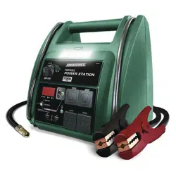
6 IN 1 Power Station

TABLE OF CONTENTS
Safety Symbols..............................................................................Page 3
Safety Information.........................................................................Page 4
Safety Precautions for Working in the Vicinity of a Battery........Page 5
Safety Precautions for Using the Charger................................... Page 6
Front and Back Panel Introduction...............................................Page 6
Operation Introduction.................................................................. Page 8
AC Charging................................................................................. Page 11
DC Charging in Your Vehicle or Boat......................................... Page 11
Major Features..............................................................................Page 12
Specifications...............................................................................Page 12
Error Code....................................................................................Page 12
Maintenance and Care................................................................Page 13
Warranty.......................................................................................Page 15
Page 3
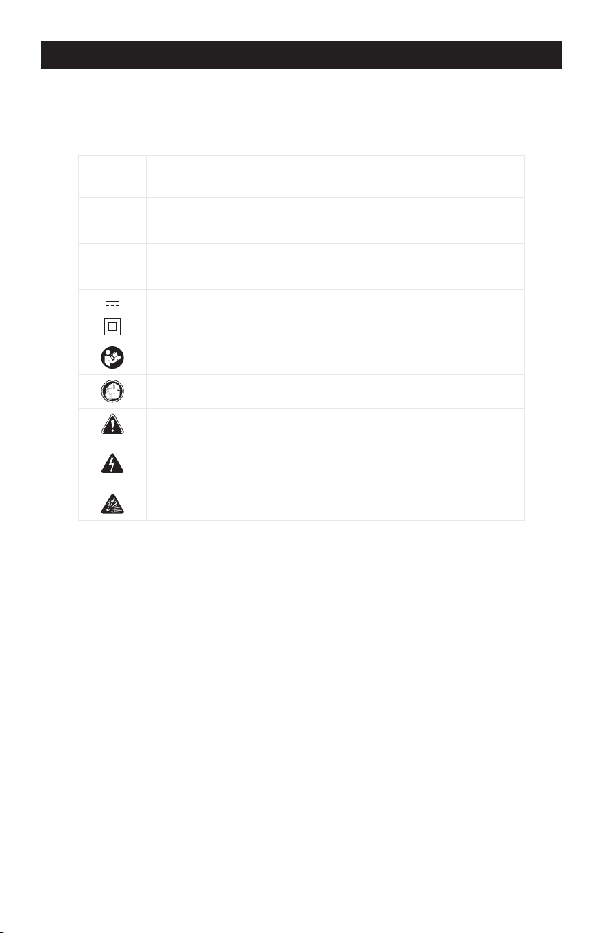
SAFETY SYMBOLS
Some of the following symbols may be used on your charger. Please study
them and learn their meaning. Proper interpretation of these symbols will allow
better and safer operation of the charger.
Symbol Name Reason/Solution
V Volts Voltage
A Amperes Current
Hz Hertz Frequency
W Watts Power
~ Alternating current Type of current
Direct current Type or characteristic of current
Class II construction Double-insulated construction
Read the operator’s
manual
To reduce the risk of injury, read and
understand the operator’s manual
Wear safety equipment
Operation of the charger can result in
damage to unprotected person
Warning symbol Alerts user to warning message
Electric shock symbol
Connect only to properly grounded
outlets. Replace defective cords or
wire immediately.
Explosive gas symbol
Risk of explosive gases during normal
operation of a lead-acid battery
Page 4
SAFETY INFORMATION
The purpose of safety symbols is to attract our attention to possible dangers. The
safety symbols, and the explanations with them, deserve your careful attention and
understanding. The symbol warnings do not by themselves eliminate any danger.
The instructions and warnings they give are no substitutes for proper accident pre-
vention measures.
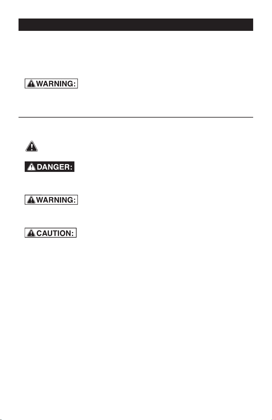
Be sure to read and understand all safety instructions in this
manual, including all safety alert symbols, such as “DANGER”, “WARNING” and
“CAUTION” before using this battery charger. Failure to follow all instructions
listed below may result in electric shock, fire and/or serious personal injury.
SYMBOL MEANING
SAFETY ALERT SYMBOL: Indicates DANGER, WARNING or CAUTION.
May be used in conjunction with other symbols or pictographs.
Failure to obey this safety warning WILL result in death or serious
injury to yourself or to others. Always follow the safety precautions to reduce the risk
of fire, electric shock and personal injury.
Failure to obey this safety warning CAN result in death or
serious injury to yourself or to others. Always follow the safety precautions to
reduce the risk of fire, electric shock and personal injury.
Failure to obey this safety warning MAY result in personal
injury to yourself or others, or property damage. Always follow the safety precautions
to reduce the risk of fire, electric shock and personal injury.

Page 5
1.
SAFETY PRECAUTIONS FOR WORKING IN THE VICINITY OF A BATTERY
1.1
1.2
1.3
1.4
1.5
1.6
1.7
1.8
Consider having someone close
enough or within the range of your
voice to come to your aid when you
work near a battery.
Do NOT smoke, strike a match, or
cause a spark in vicinity of battery or
engine. Avoid explosive gas, flames
and sparks.
Remove all personal jewelry, such as
rings, bracelets, necklaces, and
watches while working with a vehicle
battery. These items may produce a
short circuit that could cause severe
burns.
Be extra cautious to reduce risk of
dropping a metal tool onto the
battery. It might spark or short-circuit
a battery or other electrical hardware
which may cause an explosion or fire.
Wear complete eye protection, hand
and clothing protection. Avoid touch-
ing eyes while working near a battery.
Study all battery manufacturer’s
specific precautions such as remov-
ing or not removing cell caps while
charging and recommended rates of
charge.
Clean battery terminals before
connected with the charger. Be
careful to keep corrosion from
coming in contact with eyes.
When it is necessary to remove a
battery from vehicle to charge, always
remove grounded terminal from
battery first. Make sure all accesso-
ries in the vehicle are off in order to
prevent an arc.
1.9
1.10
1.11
1.12
It is NOT intended to supply power to
an extra-low-voltage electrical
system or to charge dry-cell batteries.
Charging dry-cell batteries may burst
and cause injury to persons and
property.
NEVER charge a frozen, damaged,
leaking or non-rechargeable battery.
If battery electrolyte contacts skin or
clothing, wash immediately with soap
and water. If electrolyte enters eye,
immediately flood eye with running
clean cold water for at least 15
minutes and get medical attention
immediately.
RISK OF EXPLOSIVE GASES.
a.
WORKING IN VICINITY OF A LEAD-
ACID BATTERY IS DANGEROUS.
BATTERIES GENERATE EXPLO
-
SIVE GASES DURING NORMAL
BATTERY OPERATION. FOR
THIS REASON, IT IS OF UTMOST
IMPORTANCE THAT YOU FOL
-
LOW THE INSTRUCTIONS EACH
TIME YOU USE THE CHARGER.
b.
To reduce risk of battery explo
-
sion, follow these instructions and
those published by battery manu
-
facturer and manufacturer of any
equipment you intend to use in
vicinity of battery. Review caution
-
ary markings on these products
and on engine.
JAB
C
D
E
F
G
I
H
2. SAFETY PRECAUTIONS FOR USING THE CHARGER
-
Page 6
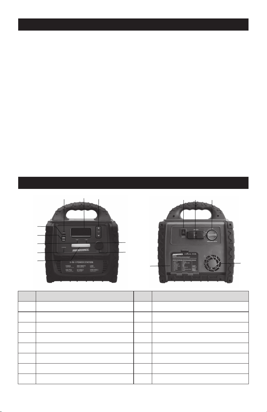
3. FRONT AND BACK PANEL INTRODUCTION
2.1
2.2
2.3
2.4
2.5
Do NOT place the charger in the
engine compartment or near moving
parts or near the battery; place as far
away from them as DC cable permits.
NEVER place a charger directly above
a battery being charged; gases or
fluids from battery will corrode and
damage charger.
Do NOT cover the charger while
charging.
Do NOT expose to rain or wet conditions.
Connect and disconnect DC output
only after setting AC cord from
electric outlet.
Use of an attachment not recom-
mended or sold by the manufacturer
may result in a risk of fire, electric
shock or injury to persons.
2.7
2.8
2.9
2.10
2.6
Do not overcharge batteries by
selecting the wrong charge mode.
To reduce the risk of damage to
electric plug and cord, pull by the
plug rather than the cord when
disconnecting charger.
To reduce risk of electric shock,
unplug charger from outlet before
attempting any maintenance or
cleaning.
Operate with caution if the charger
has received direct hit of force or
been dropped. Have it checked and
repaired if damaged.
Any repair must be carried out by the
manufacturer or an authorized repair
agent in order to avoid danger.
No.
A
B
C
D
E
F
G
H
Features
LCD Display
TYPE-C Output
USB Fast Charging QC3.0 Output
5V 2.1A USB Output
USB Switch
TYPE-C Charging Port
LED Working Light
12V DC Outlet
No.
I
J
K
L
M
N
O
Features
LED Switch
Air Compressor Switch
AC Power Inverter Switch
AC Power Outlet
Jump Starter Switch
Cooling Fan
Air Hose Storage Compartment
O
K L M
N
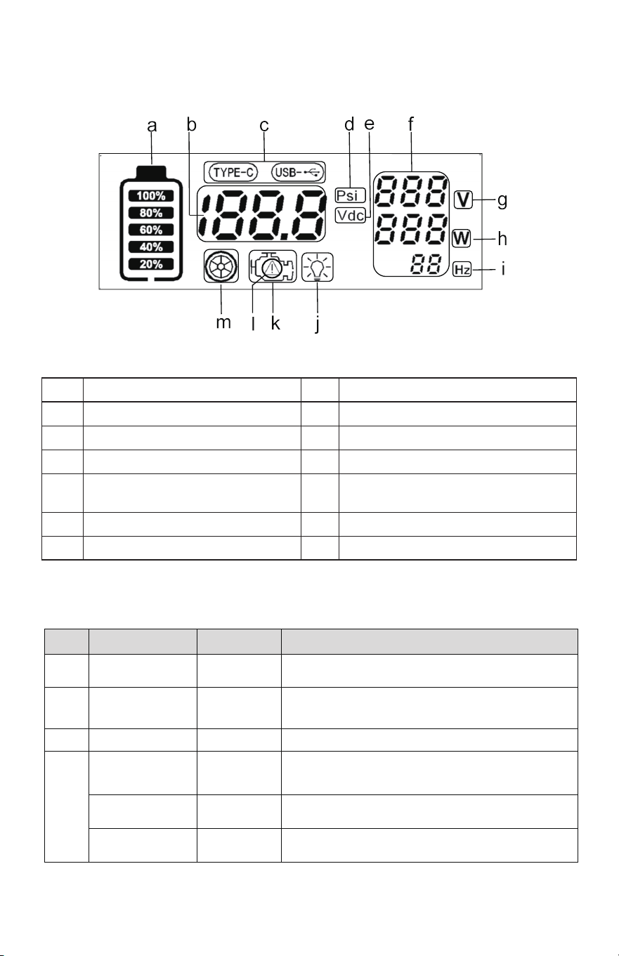
LCD DISPLAY INTRODUCTION (A)
BUTTON INTRODUCTION (K I E J)
a
b
c
d
e
f
g
Battery Level Indicator
DC Data Display
USB Function Icon
Air Compressor Pressure Display
DC Voltage Display
AC Data Display
AC Output Voltage Display
h
i
j
k
l
m
AC Output Power Display
AC Output Frequency Display
LED Working Light Icon
Jump Starter Function Icon
Jump Starter Reverse Polarity
Indicator for Safety Warning Icon
Air Compressor Function Icon
No.
Operation Buttons
Status
Function Performance
K
AC Power
Inverter Switch
ON/OFF
Set the inverter to "I" position for operation; Set the
inverter to "0" position to turn it off
I
LED Switch
ON/OFF-
Strong/Weak/
Flashing Light
E
USB Switch
ON/OFF
J
AIR compressor
Switch
ON/OFF
▲ Button Pressure+
▼ Button Pressure-
Short Press 1 →Strong light, 2→Weak light,
3→Flashing light, 4→Close light
Short press: Increase the pressure by one Psi;
long press: Rapid increase in pressure
Short Press: Decrease the pressure by one Psi;
long press: Rapid decrease in pressure
Short Press: Enter the air pump interface: Press it again
for 3 seconds: Enter the pressure setting interface Short
press it again: The motor is starting to inflate
Short Press:Turn On or Off USB Power Output
J
Page 7
Page 8
4. OPERATION INTRODUCTION
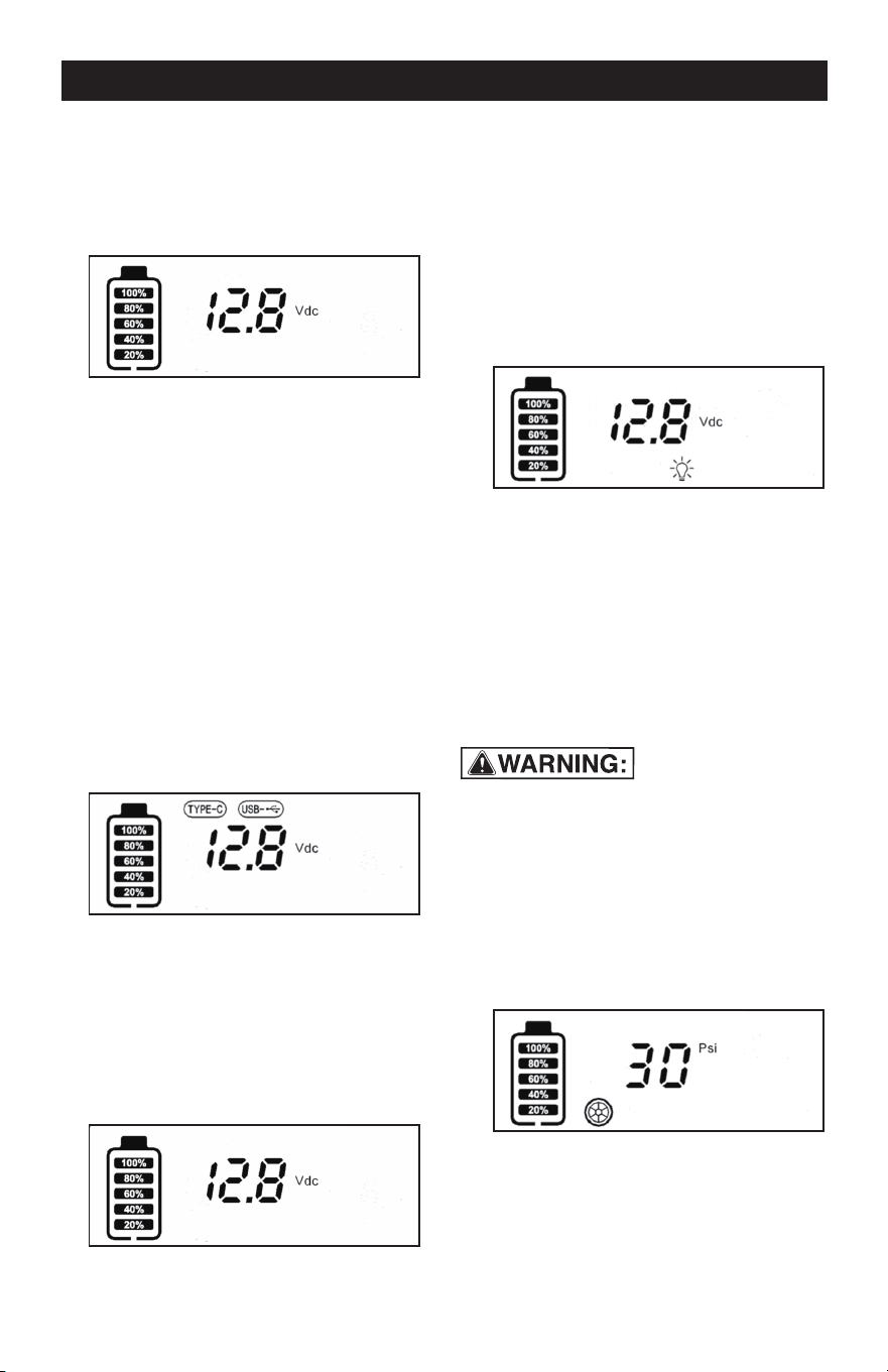
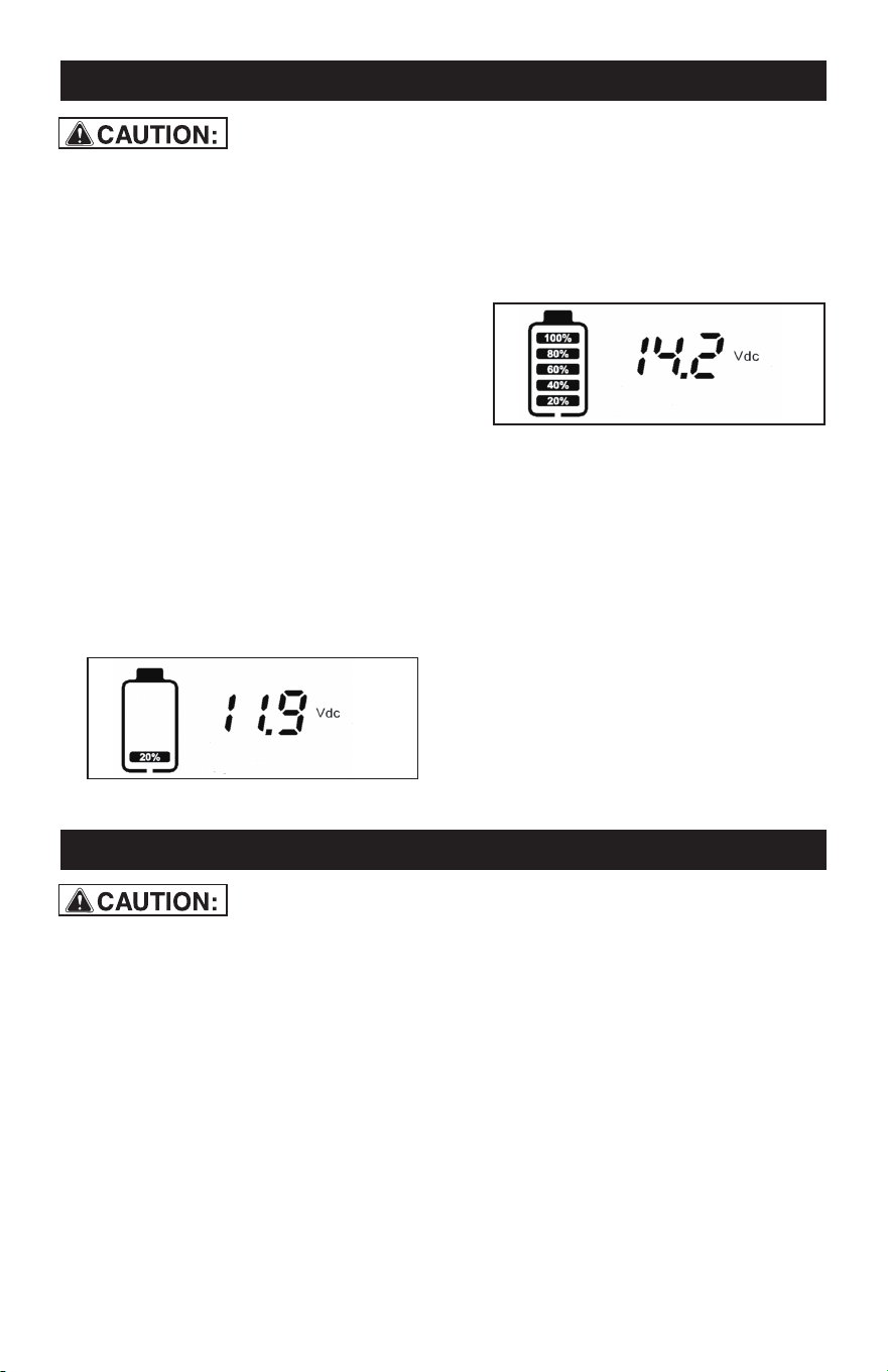
BATTERY LEVEL INDICATOR
1.
Short press any function key (excluding
the pressure setting "▲" and "▼" keys)
to display the current battery voltage
and battery level.
2.
Short press the previous operation key
again to exit the current function mode.
After 5 seconds, the display screen will
turn off and the product will enter sleep
mode.
USB BUTTON FUNCTION
1.
2.
The display screen displays the
real-time battery level and battery
voltage.
Display TYPE-C and USB icons, at the
same time the USB and TYPE-C
outputs provide the power to the
mobile device for charging.
Short press the USB button to light up the
display screen:
1.
Turn off the USB function, and the USB
and TYPE-C icons will turn off. Only the
battery level and voltage will be
displayed, and the USB will have no
power output.
Short press the USB button again to exit
the USB function, otherwise the product
cannot be shut down:
2.
If there is no operation, the display
screen will turn off after 5 seconds, and
the product will enter sleep mode.
WORK LIGHT FUNCTION
TIRE PRESSURE DETECTION
1.
Short press the "LED" button, the LED
light will light up and be in strong light
mode. The LCD displays the current
battery level and voltage, while the
lighting icon is illuminated.
1.
Connect the air pump nozzle to the car
tire, short press the "AIR" button to
display the current tire pressure "psi"
and tire icon.
2.
If the air pump nozzle is always
connected to the tire during the above
operation, the display screen will
continue to light up and the product will
remain in working condition.
2.
3.
4.
Short press the "LED" button again,
and the lighting will be in low light
mode.
Short press the "LED" button again,
and the work light will be in flashing
light mode.
Short press the "LED" button again to
turn off the lighting.
• Do not connect or disconnect the air
nozzle while the compressor is running.
• Before inflating any tire, please check the
recommended inflation pressure informa-
tion on the tire sidewall.
Page 9
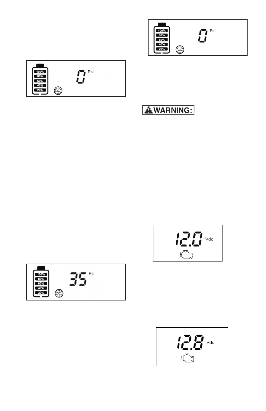
TIRE PRESSURE INFLATION
1.
2.
3.
Determine the tire pressure value that
needs to be inflated, press and hold the
"AIR" button, and the pressure value
will flash to enter the setting state.
Press the "▲" and "▼" pressure
adjustment buttons to set the pressure
value (if the inflation action is not activat-
ed within 20 seconds, it will automatical-
ly exit and turn off the display). If the
pressure value is not set this time, the air
pump will remember the last inflation
setting value for protection.
Short press the "AIR" button again to
start the inflation pump and start
inflating the tires. During the inflation
process, the display screen displays
the tire pressure in real time and the tire
icon is flashing.
When the air pressure set value is
reached, the air pump is automatically
disconnected and inflation stops.
4.
5.
If the air pump nozzle is always
connected to the tire during the above
operation, the display screen will
continue to work and the product will
remain in working condition.
After removing the air nozzle and
disconnecting it from the tire, the screen
will display "0PSI" pressure. If there is
no button operation for 5 seconds, the
inflation function will quit and then
display screen will automatically turn
off, product enters into sleep mode.
3.
Remove the air nozzle and the air
pressure will display "0 PSI". If there is
no button operation within 5 seconds,
the air pressure detection will exit. The
display screen will turn off automatical-
ly and the product enters sleep mode.
ASSIST CAR JUMP START FUNCTION
When the product's red "ON/OFF" switch is
in the "ON" position, the reverse polarity
protection is disabled and no short circuit or
reverse polarity connection should be made
at this time, as this could result in a serious
safety issue. Please pay special attention!
1.
First, turn the red On/Off switch to the
"OFF" position.
2.
The red clip is connected to the
positive pole of the car battery, while
the black clip is connected to the
negative pole or metal frame of the car.
At the same time, the display screen
shows the car battery voltage and
engine icon.
6. Do not inflate the tire for more than
15 minutes, if you need to inflate the
second tire, you need to wait for the
motor to cool for 20 minutes.
position, jump start the car (all electrical
appliances and light switches must be
turned off before jump starting the car),
and jump start for 3-5 seconds. If the
jump start is not successful, wait for 1-3
minutes before attempting a second
3. Turn the red On/Off switch to the "ON"
jump start.
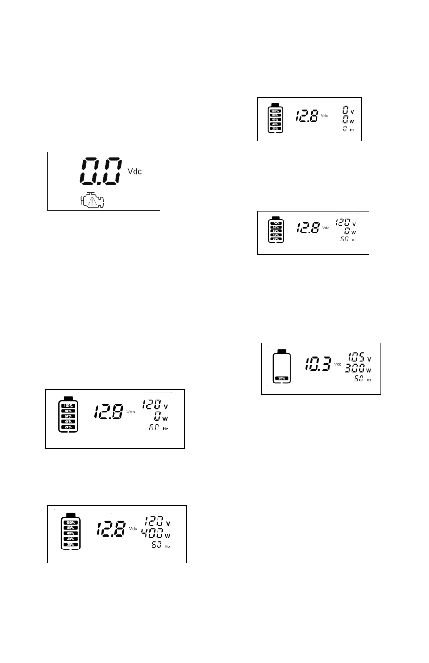
4.
If the positive and negative poles are
connected incorrectly (the On/Off
switch is in "OFF" position), the display
screen will display a voltage of "0V",
and the warning "triangle" icon in the
engine icon will flash and accompanied
by a buzzing sound. At this time, do not
turn on the jump start switch, otherwise
it will damage the product or cause a
short circuit, damage to the vehicle, or
in extreme cases, a fire or explosion.
5.
After jump starting, turn off the jump
start switch and sequentially remove
the black and red battery clips from the
car battery pole. After 5 seconds, the
display screen turns off automatically
and the product enters sleep mode.
Inverter operation
1. Set the INVERTER switch on the back
of the product to the "I" bit, and the
inverter works. Output AC voltage,
display "V" "W" "HZ"
2. Plug the AC device into the back socket
of the product, turn on the AC device,
and the display will display the current
device load power.
3. The rated power of the product is 400W.
If the power of the AC device exceeds
400W or the device has a short circuit,
the product will automatically protect
and cut off the output. At this time, the
display displays "0V" "0W" "0HZ".
4. After the product appears protection
state, please disconnect the electrical
equipment, turn off the INVERTER
switch and then open, the inverter will
will resume work.
5. After the inverter works for a
period of time, if there is an alarm
buzzer, it means that the battery
voltage of the product is too low,
then the inverter is closed, and the
product needs to be charged.
Page 10
Page 11
5. AC CHARGING
6. DC CHARGING IN YOUR VEHICLE OR BOAT
a.
Make sure the supplied AC Charging
Adapter is powered by the correct
voltage. (i.e. 110V AC).
b.
Only use the AC charging adapter
supplied with this unit.
5.1
Make sure all switches are set to OFF.
5.2
Connect the AC Charging Adapter to
the AC outlet.
5.3
Plug the Type-c cable into the
product's charging port.
5.4
During the charging process, the
display screen will light up and display
the battery icon and flash, as well as
the real-time voltage of the product.
The battery level in each cell represents
20%. During the charging process, for
each fully charged cell, the battery level
will increase by another cell, totaling 5
cells.
6.1
Make sure all Product switches are set
to OFF.
6.2
Plug the Type-c cable into
the
product's charging port.
6.3
Plug
the other end of the Type-c
cable
5.5
Initial AC charging can take up to 20
hours.
6.4
The display screen will light up during
5.6
When all 5 battery cells are lit without
blinking, it indicates the product is fully
charged. In order to be 100% charged,
it is recommended to extend the
charging time by about 2 hours.
5.7
the charging process, displaying the
battery icon and flashing, as well as the
real-time voltage of the product. The
battery level in each cell represents
20%, with a total of 5 cells.
6.5
Do not charge more than 20 hours
using the DC method.
blinking, it indicates the product is fully
charged.
6.6
When all 5 battery cells are lit without
After charging the battery, disconnect
the adapter from the AC outlet first,
then from the charging jack. If there is
no operation of the product within 5
seconds, the display screen will turn off
automatically, and the product will
enter sleep mode.
into the USB output port of your
vehicle or boat.

7. MAJOR FEATURES
8. SPECIFICATIONS
• 1400 Amp jump starter with heavy-duty cable and clamps
• 100 PSI high flow air compressor for inflating tires and accessories
• Easy read LCD screen display
• 400 watts power inverter (800 watts peak)
• Two AC 110 volt outlet
• One 12 volt accessory outlet for power DC appliances (loads up to 11 amps)
• 4xUSB power outlet( QC3.0 and TYPE -C)
• Bright COB LED working light
• AC recharging adapter
Page 12
Sealed Lead Acid - Rechargeable Battery
Work light - Strong/Weak/Flashing Light
Compressor
Inverter Output - AC outlet
Inverter Peak Power
12 Volt Accessory Outlet
USB Power Port Output-2
USB Power Port Output-3
USB Power Port Output-4
Charging Time from Discharge
AC Charger
12 Volt, 18 Amp Hour
COB 3W LED
100PSI
110 Volts AC 60 HZ
400 Watts-800 Watts Peak ( Max of 0.3 Sec.)
11Amps Max
TYPE-C 18W
QC3.0 18W
5 Volt up to 2.1A
20 Hours
5V 2A

9. ERROR CODE
No.
PROBLEM
CAUSE SOLUTION
1
Lack of power output
(1) Recharge the power center
immediately.
(2) Reduce load to maximum 400 watts
by following five steps.
• Turn off the device and inverter.
• Disconnect the device.
• Turn the inverter on for a minimum of
2 minutes.
• Turn off inverter, quickly plug in the
device to the inverter, making sure
the device is off prior to connection.
• Turn on the inverter and the device.
Succession 5 times in order to generate
the necessary power to start the device.
If the device does not start up in 5 cycles
of ON/OFF trials, this inverter will not
work with the device.
(1) Power center voltage
below 10 volt
(2) Excessive current
drawn by appliance
being operated
Television/power tool
will not start
High surge wattage
requirement to start-up
Television interference
Move the power station as far as possible
from TV, the antenna and the coaxial cable.
Television picture
breaking up (snow)
1
2
3
Page 13
10. MAINTENANCE AND CARE
• All batteries lose energy from self-dis-
charge over time and more rapidly at
highertemperatures. When the unit is not
in use, we recommend that the battery
ischarged at least every 30 days.
• From time to time wipe the outside of the
appliance with a soft cloth. Do notimmerse
the appliance in water.
• There are no user-replaceable parts.
Periodically inspect the condition of adapt-
ers,connectors and wires.
SAFE BATTERY DISPOSAL
• Contains a maintenance-free, sealed,
non-spillable, lead acid battery,which must
be disposed of properly.
• Recycling is required. Failureto comply
with local, state and federal regulations can
result infines, or imprisonment. Please
recycle.
• Do not dispose of the battery in fire as this
may result in an explosion. Before dispos-
ing of the battery, protect exposed
terminals with heavy-dutyelectrical tape to
prevent shorting (shorting can result in
injury or fire). Do not expose battery to fire
or intense heat as it may explode.
BATTERY
• Please be advised that the battery is
designed to last the service life of the
unitand is not replaceable, removable or
serviceable.
• Service life is dependent on anumber of
factors including but not limited to the
number of recharge cycles, andproper care
and maintenance of the battery by the end
user.

Page 14
NOTES

6 IN 1 Power Station
WARRANTY
90-DAY MONEY BACK GUARANTEE
This MASTERFORCE™ brand battery charger carries our 90-Day Money Back
Guarantee. If you are not completely satisfied with your MASTERFORCE™
brand product for any reason within ninety (90) days from the date of purchase,
return the item with your original receipt to any MENARDS
®
retail store, and we
will provide you a refund – no questions asked.
3-YEAR LIMITED WARRANTY
This MASTERFORCE™ brand battery charger carries our famous No Hassle
3-Year Limited Warranty to the original purchaser. If, during normal use, this MAS-
TERFORCE™ product breaks or fails due to a defect in material or workmanship
within three (3) years from the date of original purchase, simply bring the item
with the original sales receipt back to your nearest MENARDS
®
retail store. At its
discretion, MASTERFORCE™ agrees to ha
ve the item or any defective part(s)
repaired or replaced with the same or similar MASTERFORCE™ product or part
free of charge, within the stated warranty period, when returned by the original
purchaser with original sales receipt. Not withstanding the foregoing, this limited
warranty does not cover any damage that has resulted from abuse or misuse of
the Merchandise. This warranty: (1) excludes expendable parts including but not
limited to blades, brushes, belts, bits, light bulbs, and/or batteries; (2) shall be
void if this product is used for commercial and/or rental purposes; and (3)
does
not cover any losses, injuries to persons/property or costs. This warranty does
give you specific legal rights and you may have other rights, which vary from
state to state. Be careful, battery chargers are dangerous if improperly used or
maintained. Seller’s employees are not qualified to advise you on the use of this
merchandise. Any oral representation(s) made will not be binding on seller or its
employees. The rights under this limited warranty are to the original purchaser
of the merchandise and may not be transferred to any subsequent owner. This
limited warranty is in
lieu of all warranties, expressed or implied including war-
ranties or merchantability and fitness for a particular purpose. Seller shall not be
liable for any special, incidental, or consequential damages. The sole exclusive
remedy against the seller will be for the replacement of any defects as provided
herein, as long as the seller is willing or able to replace this product or is willing
to refund the purchase price as provided above. For insurance purposes, seller
is not allowed to demonstrate any of these products for you.
For questions/comments, technical assistance or repair parts—
Please call toll free at: 1-877-898-3958.
Page 15

© 2024 Menard, Inc., Eau Claire, WI 54703
01/2024