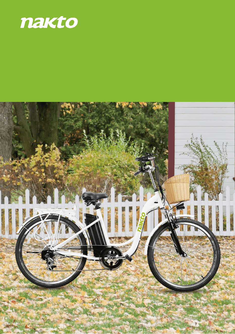
Camel
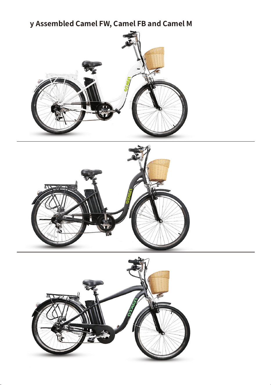
Fully Assembled Camel FW, Camel FB and Camel MB.
CAMEAL FW
CAMEAL FB
CAMEAL MB
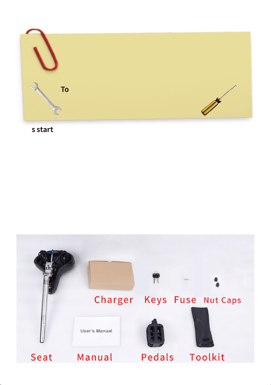
Let’s start assembling your NAKTO Camel ebike!
(Please read this entire assembly manual before assembly as it will save
you a lot of time!)
Step One: Unpack the ebike.
1.Pull the frame and all parts (charger, seat, tool kit, keys & spare fuse,
nut caps, manual and pedals) out of cardboard box. Separate bike from
foam padding. Cut off all zip ties with scissors while being extra careful
as not to damage the paint or cut any wires or cables.Notice: The spare
is not used for assembly. Keep it in a safe place that it will be used for the
replacement if the original fuse were damaged.
Ensure all the following pieces are included with the Nakto Camel.
Tools included: Screwdriver, Phillips/Slotted 2 in 1
Double open-end wrench, 13mm/15mm
Allen wrench, 5mm
Allen wrench, 6mm
Tools needed: Scissor
Bike pump
Assembly Instructions: Camel
2.Now stand the bike upright. Place some foam padding under the front
fork if placed on the ground or put it on bike assembly/repair stand if you
have one. We want to keep your bike looking new!
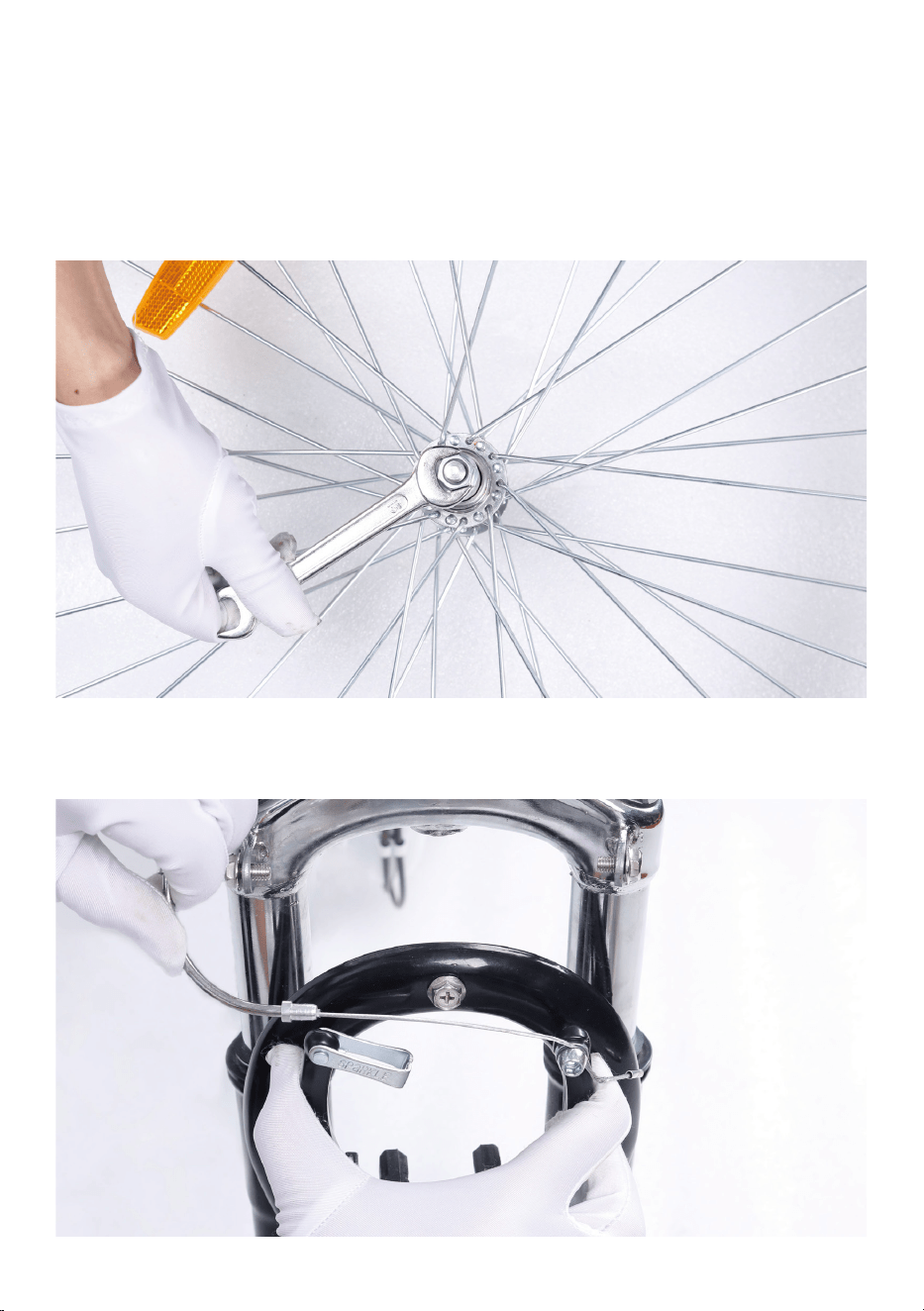
Step Two: Assemble the front wheel.
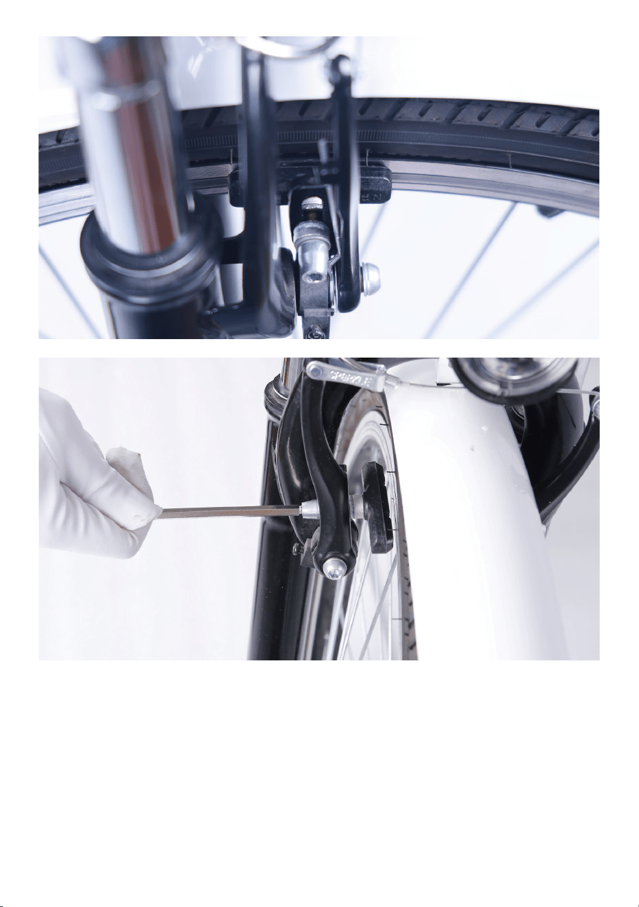
1.Loosen axle nuts on front wheel to make room for the front fork.
2.Remove the brake cable from the linkage of the left arm while squeez-
ing the brake arms to make room for the front wheel.
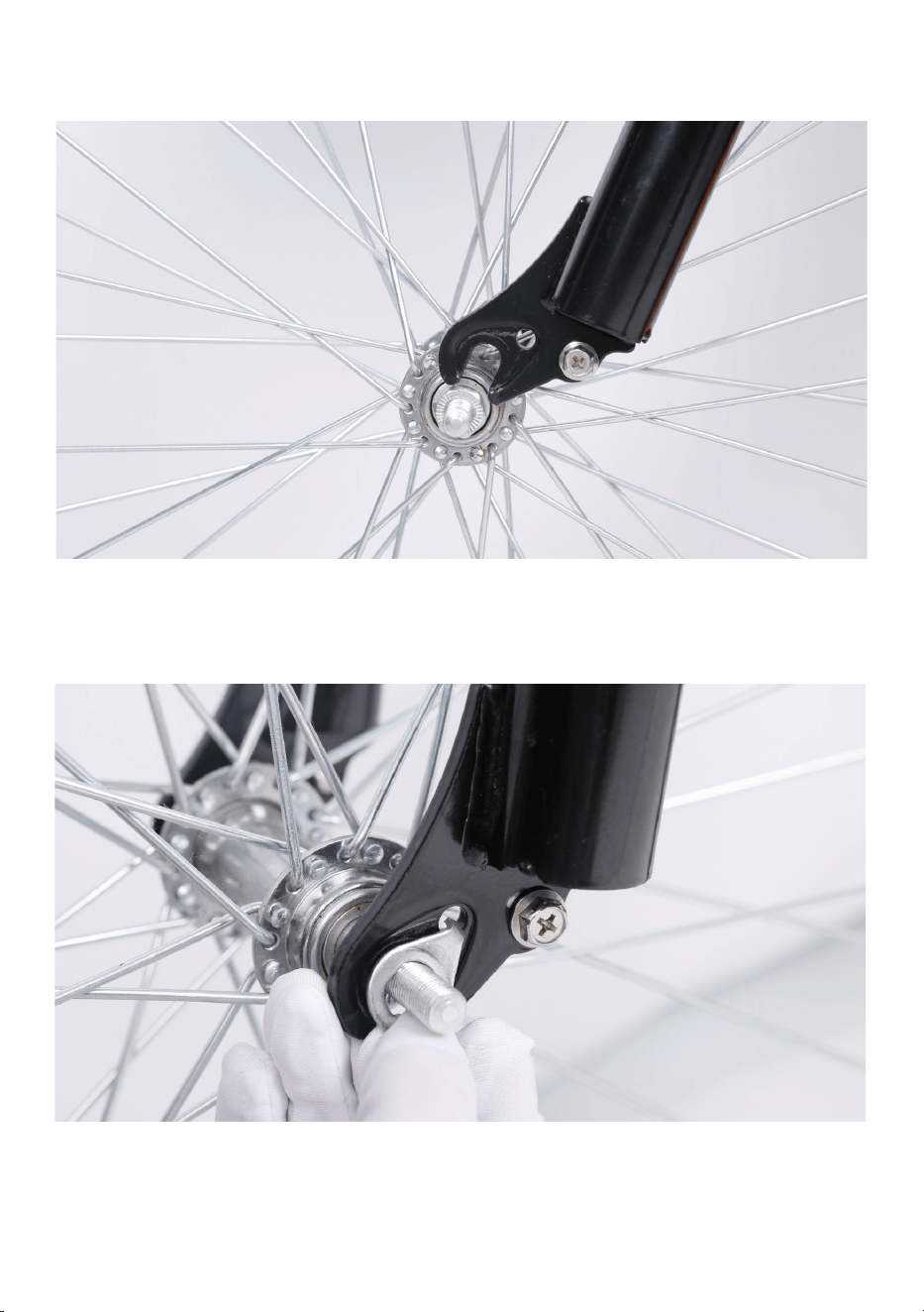
3.Lift the front of the bike and lower the fork onto the wheel. Notice: The
axle should enter the fork dropouts fully.
4.Line up the axle lock washers (These are the metal washer with a bent
tab on one side) with the hole at each fork. Notice: These two special
fork lock washers keep the wheel from falling off if the axle nuts ever
loosen up! Tighten axle bolts by hand.
5.Once the lock washers are in place, tighten both axle nuts with the
supplied double open-end wrench. Notice: Before doing the final tight-
ening of the axle nuts make sure the wheel is square and true with the
forks.
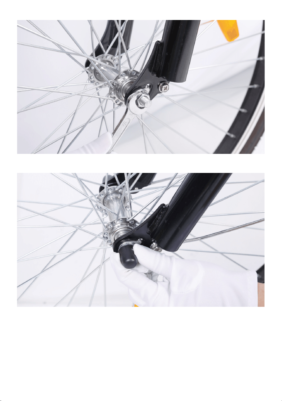
6.Push the black plastic caps onto the nuts.
7.Put the brake cable back to the linkage of the left arm while squeezing
the brake arms .
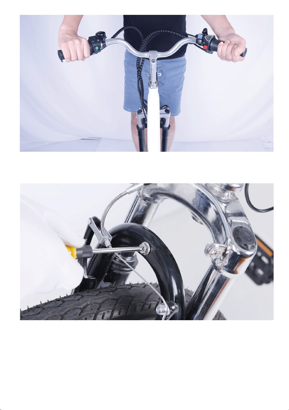
2.Set the stem to the desired height but not exceed max height or mini-
mum insertion.
3.Align the stem so the handlebar is perpendicular to the front wheel.
Step Three: Install the handlebar stem into the steer tube.
1.Insert handlebar stem into the neck of the frame.
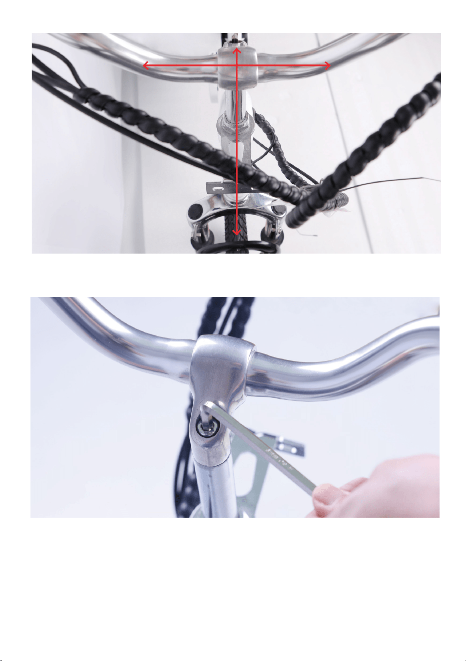
5.Perform a twist test.
(1).Brace the front wheel between your legs.
(2).Switch hands so the opposite hands are pushing and pulling with
about 20 pounds of force make sure the handlebar and front wheel are
still properly aligned.
(3).Repeat the twist test pulling/pushing with the opposite hands.
4.Tighten the bolt on top of the handlebar stem with the supplied allen
wrench.
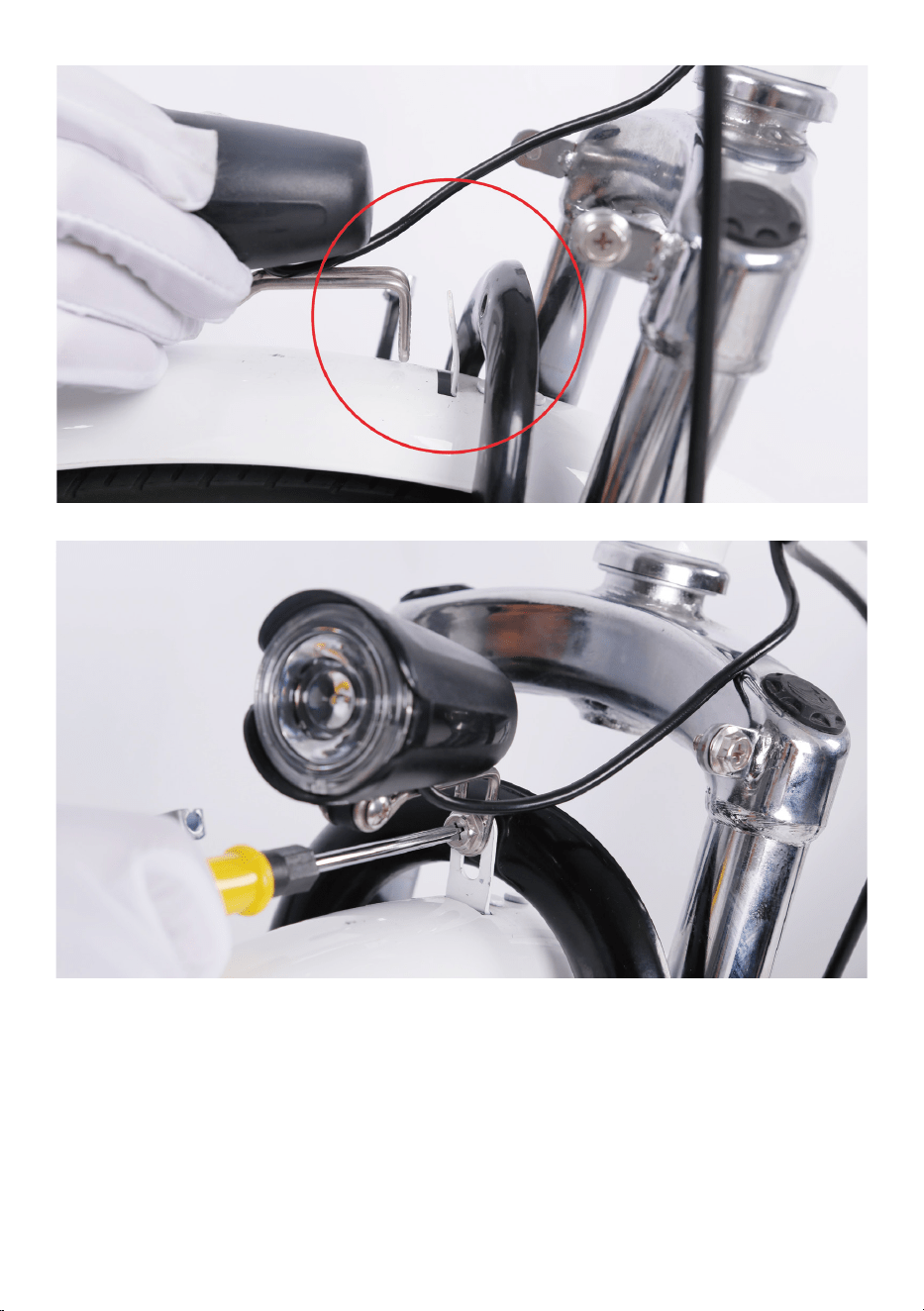
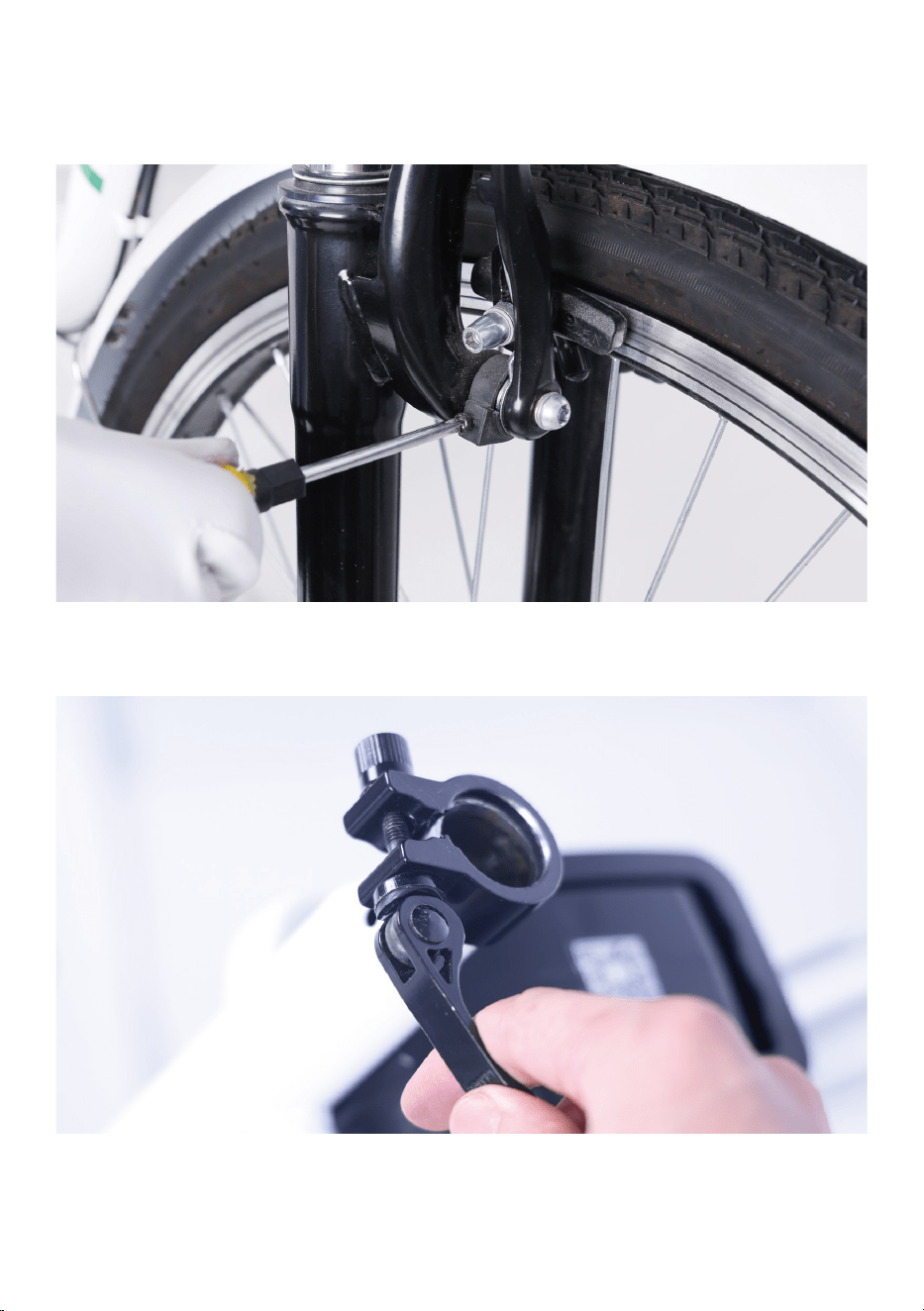
2.Place the fender in position. From the back of the front tire, pass the
front fender mounting point under the front fork arch.
3.Attach the headlight and fender to the fork arch. Pass the bolt through
the headlight mount, fender mounting point and fork arch mounting
point. Notice: the fender bracket should go in between the arch bracket
and headlight bracket. Thread the locknut at the bolt end and tighten
with the supplied screwdriver.
Step Four: Install the front fender and headlight.
1.Remove the fender and headlight mounting bolt from the fork arch with
the supplied screwdriver and set aside.
4.Attach the fender mounting arms to the front fork. Remove the mount-
ing bolts from the fork. Pass the bolt through the arm mount and fork
mounting point. Ensure the fender is centered and tighten both the
mounting bolts.
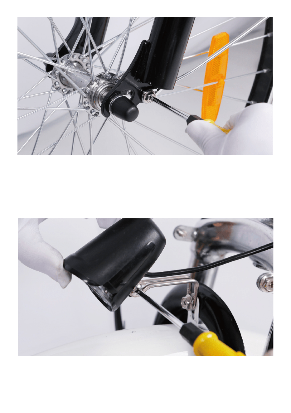
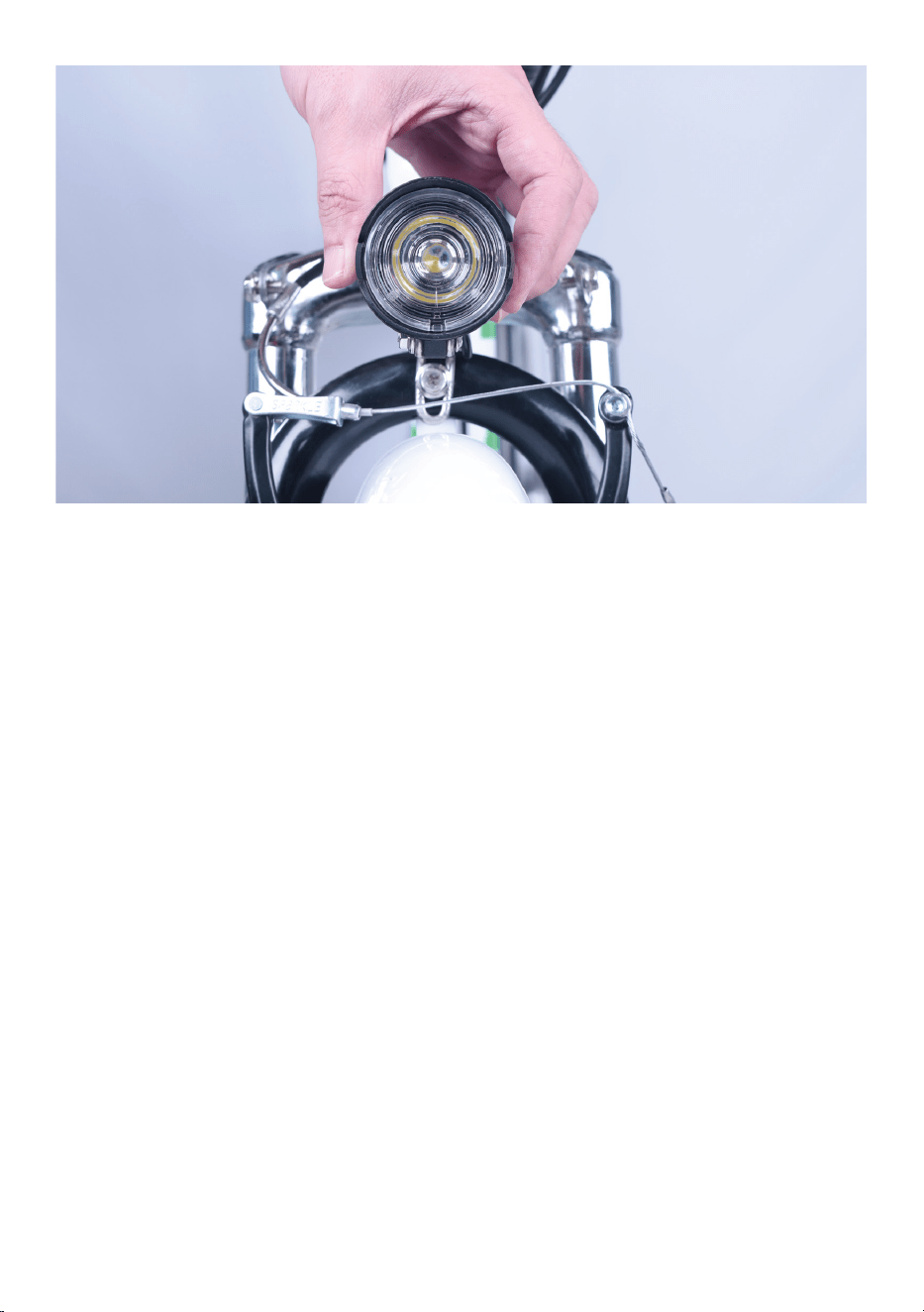
5.Center the headlight and adjust the angle slightly downwards to illumi-
nate the road ahead and not blind oncoming traffic. Use the supplied
Phillips-head screwdriver to loosen the headlight angle adjustment bolt,
tilt the headlight to the optimal position, and then tighten in place
securely.
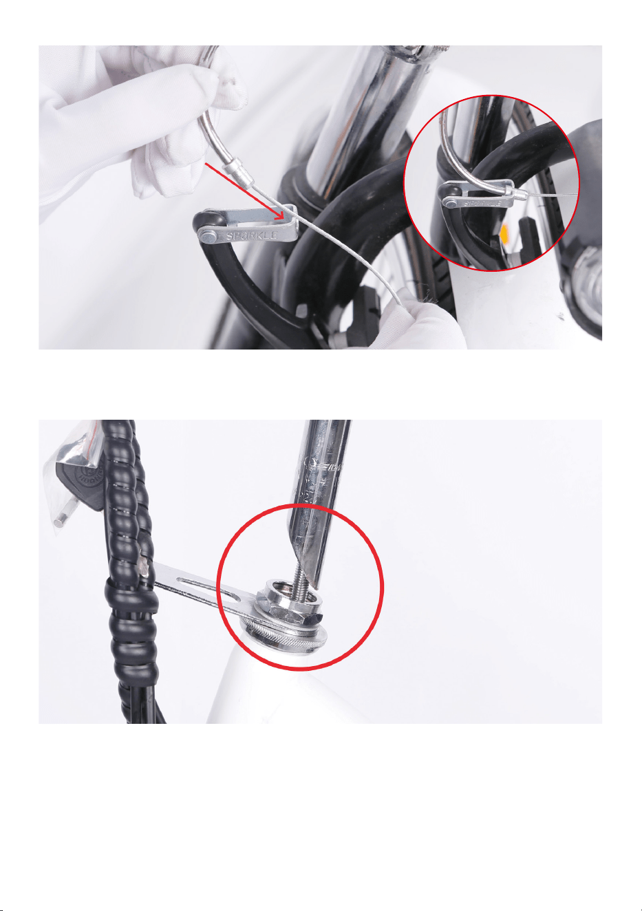
Step Five: Adjust the front brake system.
NOTICE: The The adjustment of the front brake system is not easy. The
following steps are only a general guide to assist in the adjustment of the
front brake system. Consult a certified, reputable bike mechanic to assist
with it.
1.Pad Adjustment.
Remove the brake cable from the linkage of the left arm while squeezing
the brake arms.
Loose the pad mount, bring the arm and pad to the rim, and adjust.
Locate the pad to the top edge of the braking surface. Notice: Do not
locate the pad to the top edge of the rim. It would hit the tire.
Bring the pad gently to the rim and push with some mild force and secure
the nut. The pad will tend to be self-aligning and put the convex-concave
washers where it needs to be correctly aligned with two flat surfaces, the
rim and the pad-aligned. Hold the pad as you tighten the final tightness.
Repeat the process on the other side.
Put the brake cable back to the linkage of the left arm while squeezing
the brake arms.
2.Cable Attachment.
Before we draw the pads together, back out the barrel adjusters three or
four turns. So that we can have some fine tuning at the lever.
Loosen the pinch bolt.Pull the arms together with your hand and pull the
cable out with some mild force. It is only necessary to get the rim close.
Then secure the pinch bolt. It should flatten and crush the cable.
3.Set Pad Clearance.
Bring the barrel adjuster in toward the lever, giving more slack. Typically,
the pads should feel like they are contacting the rotor at a minimum of
1/2 the lever travel.
4.Centering.
Centering is done by subtle changes in spring tension. There are screws
to the return spring on both sides. By tightening the screw, you are
increasing tension on whatever side you tighten. The end goal here is to
Step Six: Install the seat.
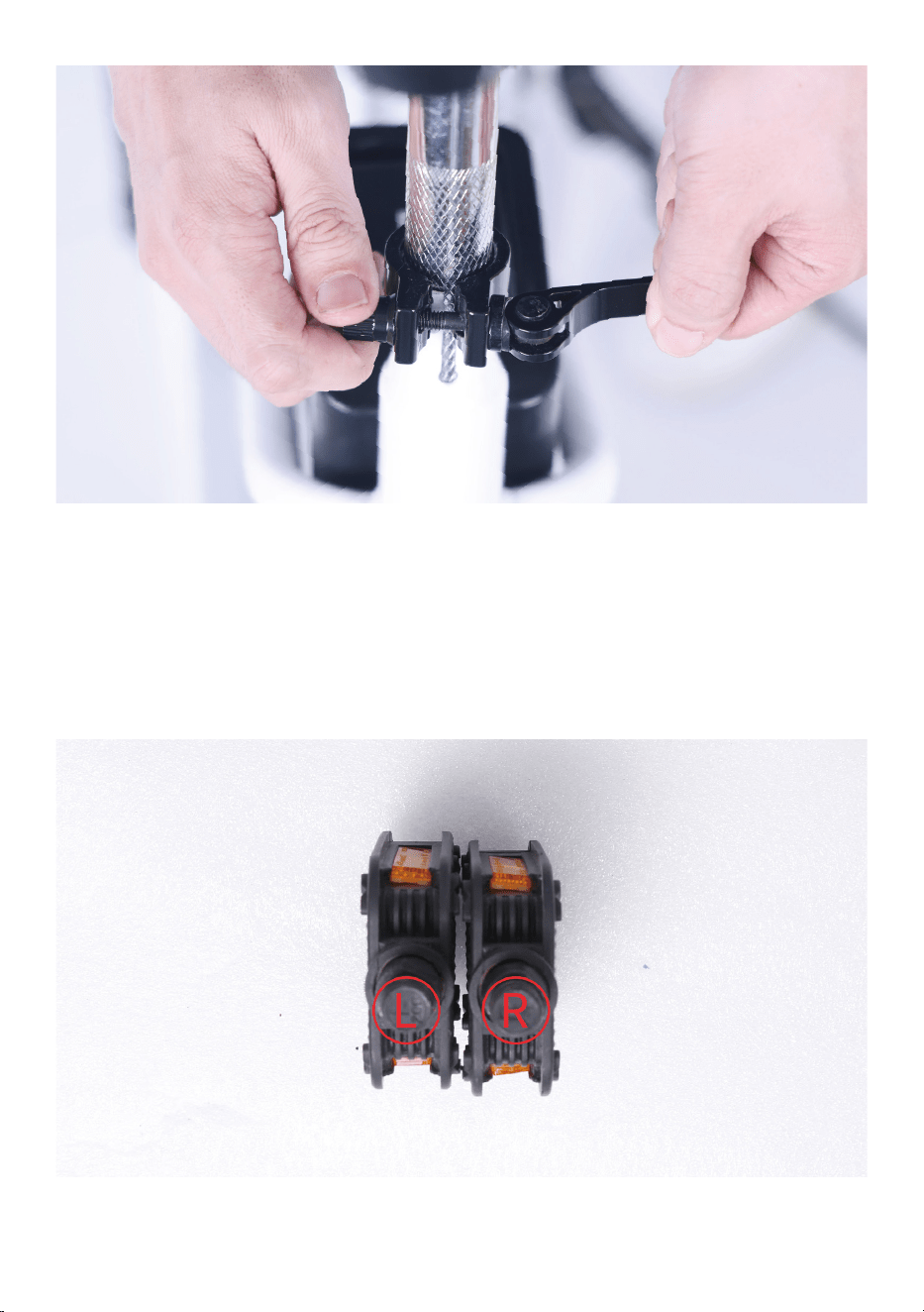
1.Open the quick release lever by hinging it open fully.
2.Insert seat post into seat tube. Adjust the seat post up or down to a
comfortable height, while ensuring the seat post is inserted into the
frame past the minimum insertion point.
keep even pad clearance on either side of the rim. Take the right pad for
example, we can tighten to make it far from the rim, or loosen the screw
to make it close.
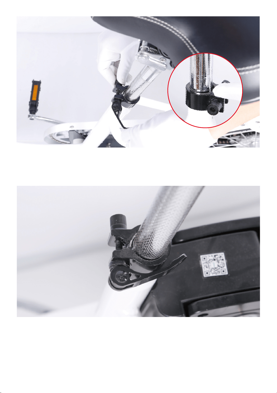
3.Close the quick release lever to secure the seat post and check that it
cannot move. If needed, use the thumb nut to add tension to the clamp
so there is some resistance when the lever is in line with the clamp bolt.
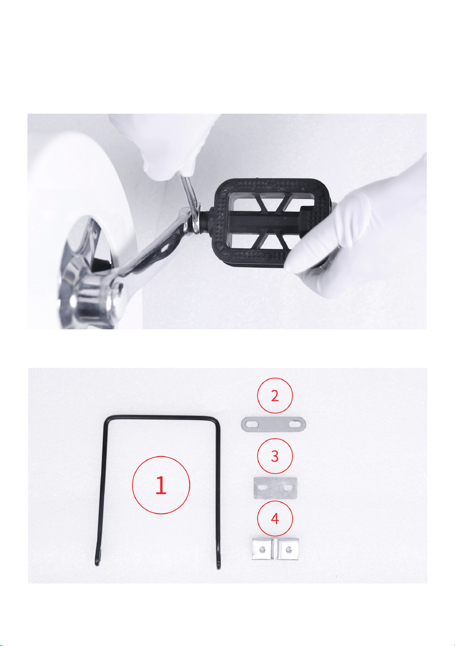
Step Seven: Install the pedals.
1.Locate the pedal with an “R” stamped into the end of the pedal axle,
which indicate it is the right pedal. The right pedal goes on the crank on
the right side of the bike. The remaining pedal with an “L” stamped into
the end of the axle, is the left pedal. The left pedal goes on the crank on
the left side of the bike.
Step Eight: Install basket.
2.The right pedal is threaded to tighten by turning clockwise. The left
pedal is reverse-threaded and tightens counterclockwise. Carefully
thread the pedal onto the crank by hand slowly.
3.Further tighten with the supplied double open-end wrench. Do not
cross thread or damage the threads.
1.Remove the fender mounting bolts of the basket on top of the front
fork with the supplied screwdriver. Pass the bolt through the fender
mounting point and the bottom bracket (bracket 1) mounting point.
Thread the lock nut onto the bolt end and tighten with the supplied
screwdriver.
2.Fix the basket to the mount extending from the stem of the handlebar.
Pass the bolt through “bracket 2” mounting point, the basket mounting
point and the mount extending from the stem of the handlebar. Thread
the lock nut onto the bolt end and tighten with the supplied screwdriver.
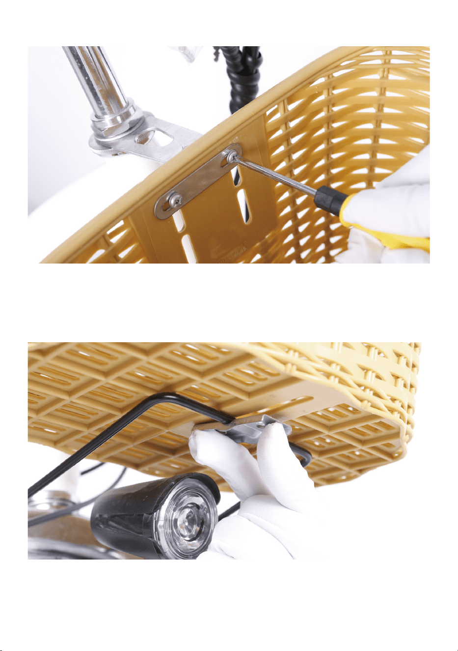
3.Fix the basket to the bottom bracket. Fit the bottom bracket into the
curve of “bracket 4”. Pass the bolt through “bracket 3” mounting point,
the basket bottom mounting point and “bracket 4” mounting point.
Tighten with the supplied screwdriver.
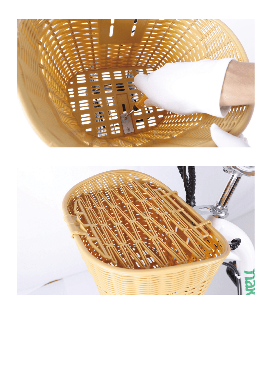
4.Snap the cover into place.
Step Nine: Inflate the tires.
Check that the tire beads and tires are evenly seated around the rims.
Use a pump with a Schrader valve and pressure gauge to inflate each tire
to the recommended pressure indicated on the tire sidewall. Do not
overinflate or underinflate tires.
Step Ten: Ensure the battery is locked to the frame before
riding.
Operate the electrical system when the battery has been adequately
charged and the battery is secured to the frame mount.
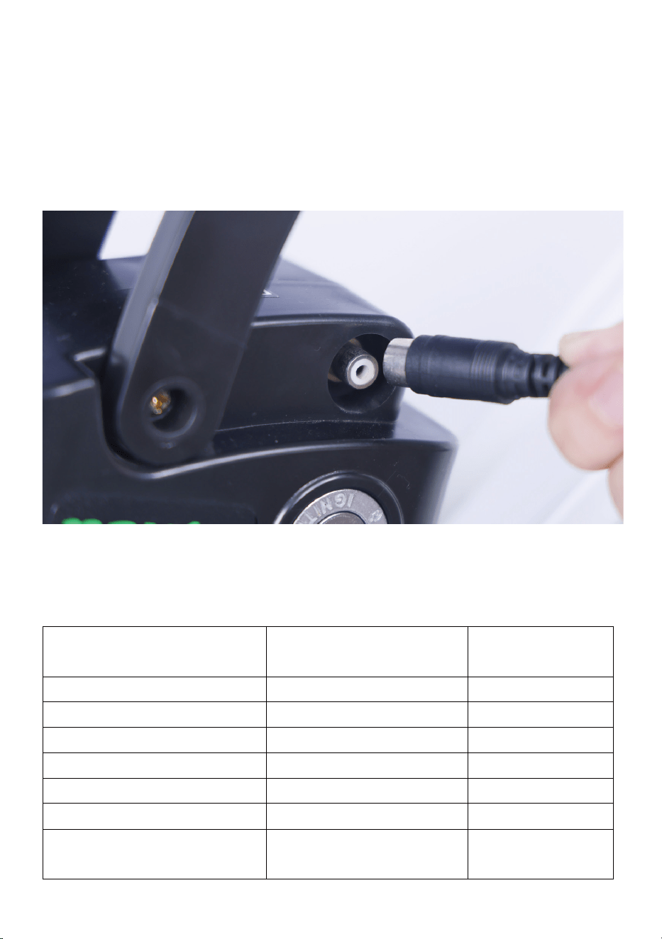
Your Nakto bike comes partially charged. We recommend you Connect
the charger input plug (110/220-volt plug) to the power outlet for 3 to 4
hours. The charger light will go from red to green when it is fully charged.
Step Eleven: Ensure all hardware is tightened properly
following recommended torque values.
Recommended Torque Values:
Hardware Loca�on Hardware
Torque Required
(Nm)
Front Dropout Area
Front Axle Nuts
40
Handlebar Area
Handlebar Stem Bolts
10
Handlebar Area
Brake Lever Clamp Bolt
6
Handlebar Area
Shi�er Clamp Screw
6
Brakes
Caliper Adapter to Frame
8-10
Brakes Pad to Caliper Arm 6
Brakes
Brake Cable to Caliper
Clamp
6

Step Twelve: Register warranty card with us ASAP.
Notice: Keep proof of purchase in a safe place. Keep packing and box for
at least two weeks from the date of purchase. (As we do not provide a box
for returns if needed.)
Have fun and be safe!
Hardware Loca�on Hardware
Torque Required
(Nm)
Fenders
All Fender Moun�ng Bolts
and Hardware
6
Headlight
Headlight Angle
Adjustment Bolt
6
Basket Area
All Basket Moun�ng Bolts
and Hardware
6
Seatpost Area
Seat Angle Adjustment
Bolt
20
Rear Dropout Area Rear Axle Nuts 40
Rear Dropout Area
Rear Torque Arm Bolt
5
Rear Dropout Area
Derailleur Hanger
Moun�ng Bolt
6
Rear Dropout Area Derailleur Moun�ng Bolt 10
Rear Dropout Area
Derailleur Cable Pinch
Bolt
6-8
Rear Dropout Area
Kickstand Moun�ng Bolts
8
Bo�om Bracket and Crank
Area
Bo�om Bracket and
Lockring
60
Bo�om Bracket and Crank
Area
Crank Arm Bolt into
Bo�om Bracket Spindle
35
Bo�om Bracket and Crank
Area
Pedal into Crank Arm 35
Bo�om Bracket and Crank
Area
Chainring Bolts 10
Bo�om Bracket and Crank
Area
Controller Moun�ng Bolts
6
Quick Start Guide
This ebike is equipped with two ways for a rider to use power assistance
from the motor to propel the bike forward:
The pedal assist system (PAS) ⸺The rider can engage the pedal assist
system (PAS) while pedaling, and it will call up assistance from the motor
to help propel the bike forward.
The twist throttle⸺The throttle is located on the right side of the
handlebar. The rider can use it with a twist of the throttle grip to propel
the bike forward without pedaling.
Warning: The throttle is active whenever the bike is turned on. Do not
use the throttle unless you are on the bike.
Start-Up Procedure
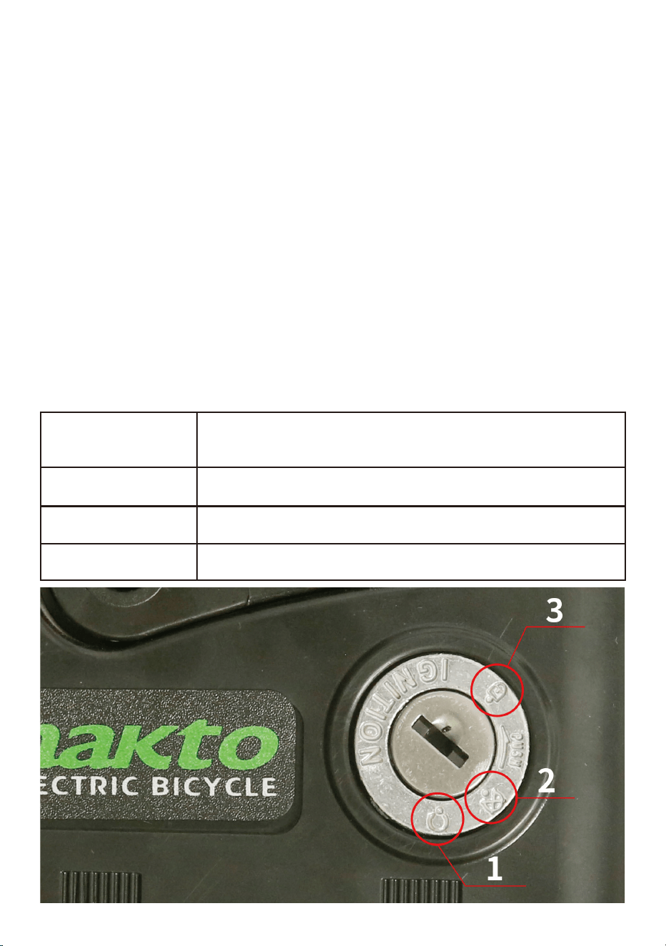
1.Turn on the battery with the key. Insert the key and turn clockwise to
position (1).
Battery Key Positions
Key Position /
Icon
Description
1
2
3
ON , Locked to the frame
OFF, Locked to the frame
OFF, Unlocked (ready for removal from the frame)
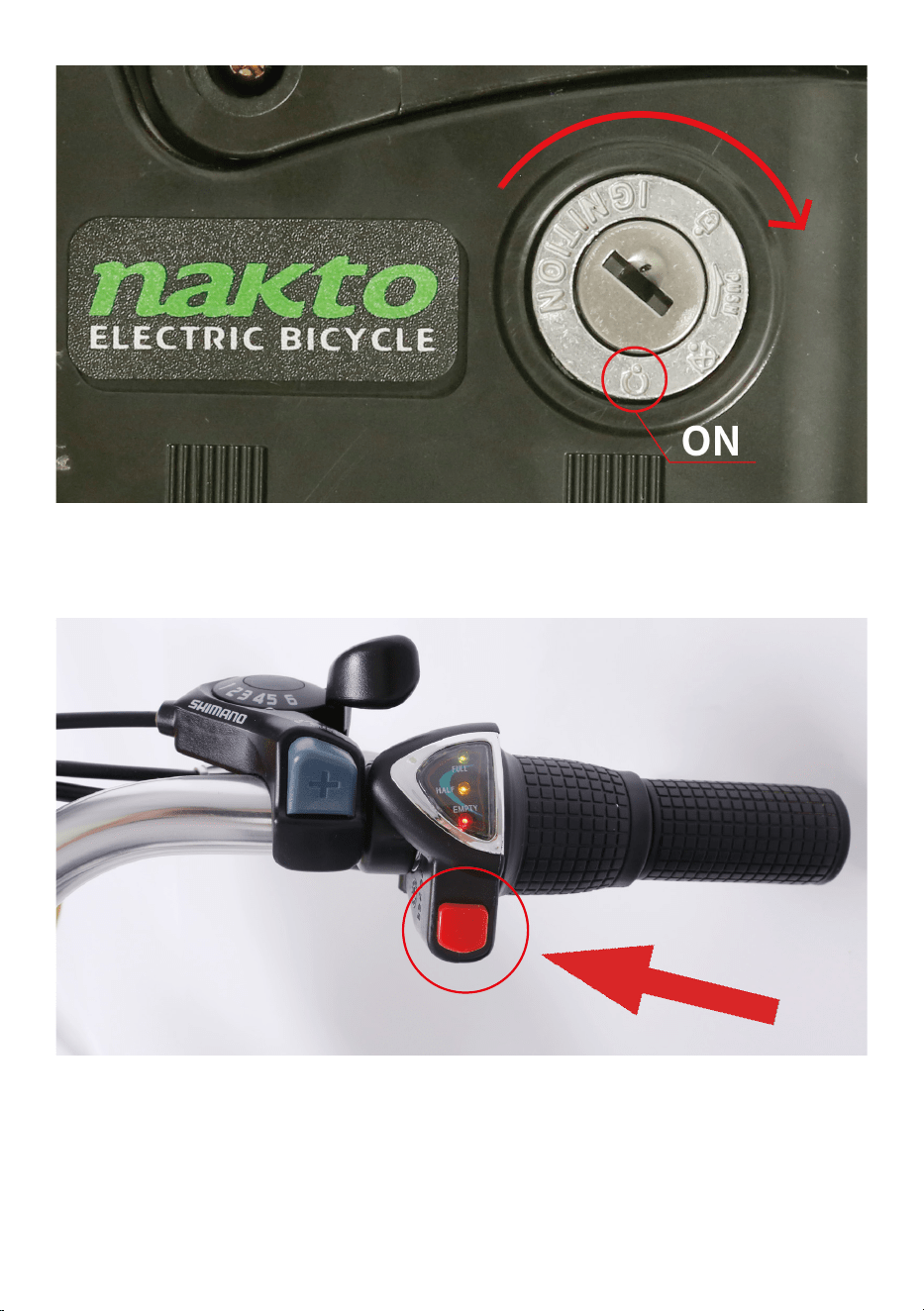
2.Sit on the bike.
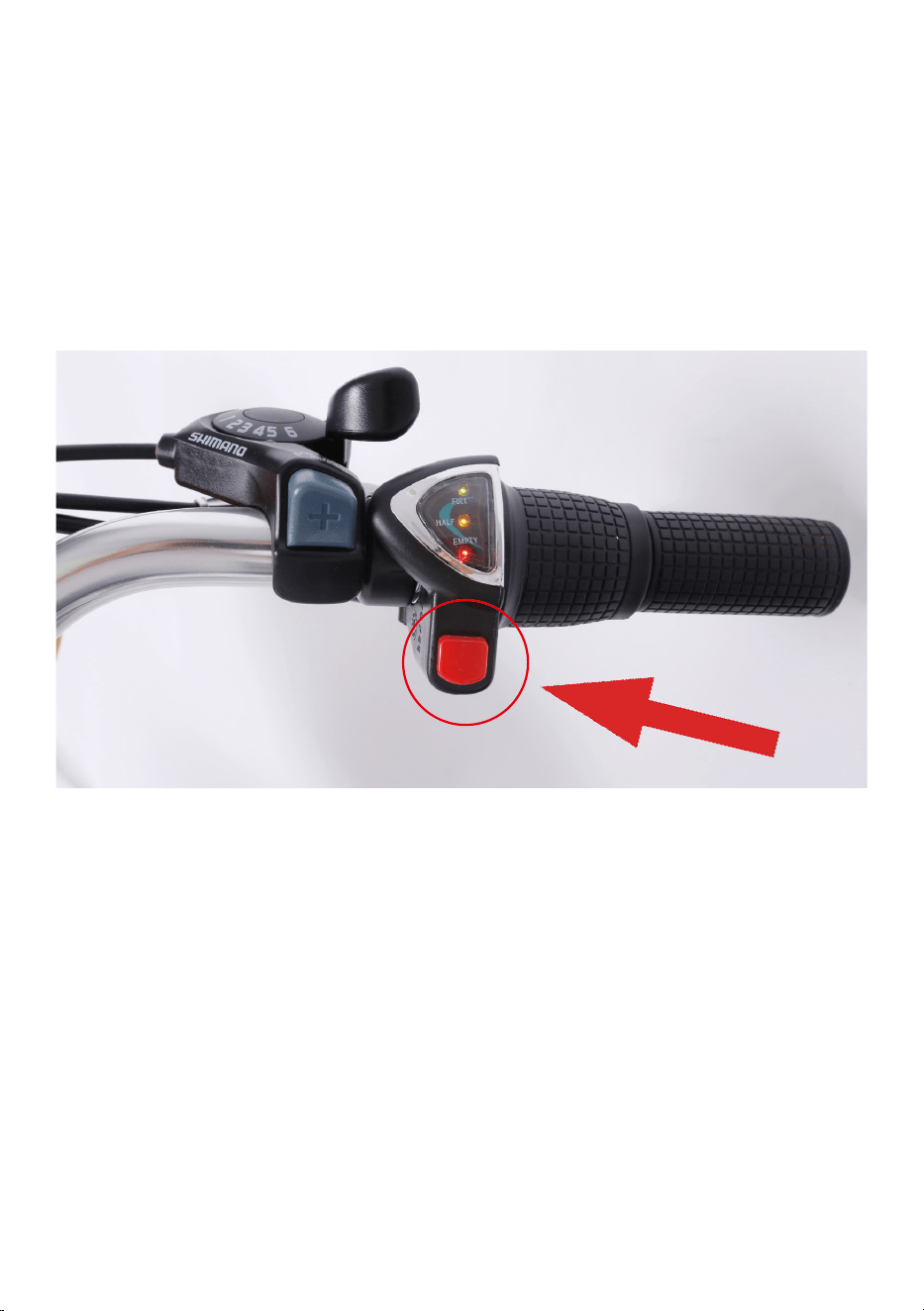
3.Activate the pedal assistance system⸺Press the red button on the
right side of the handlebar.
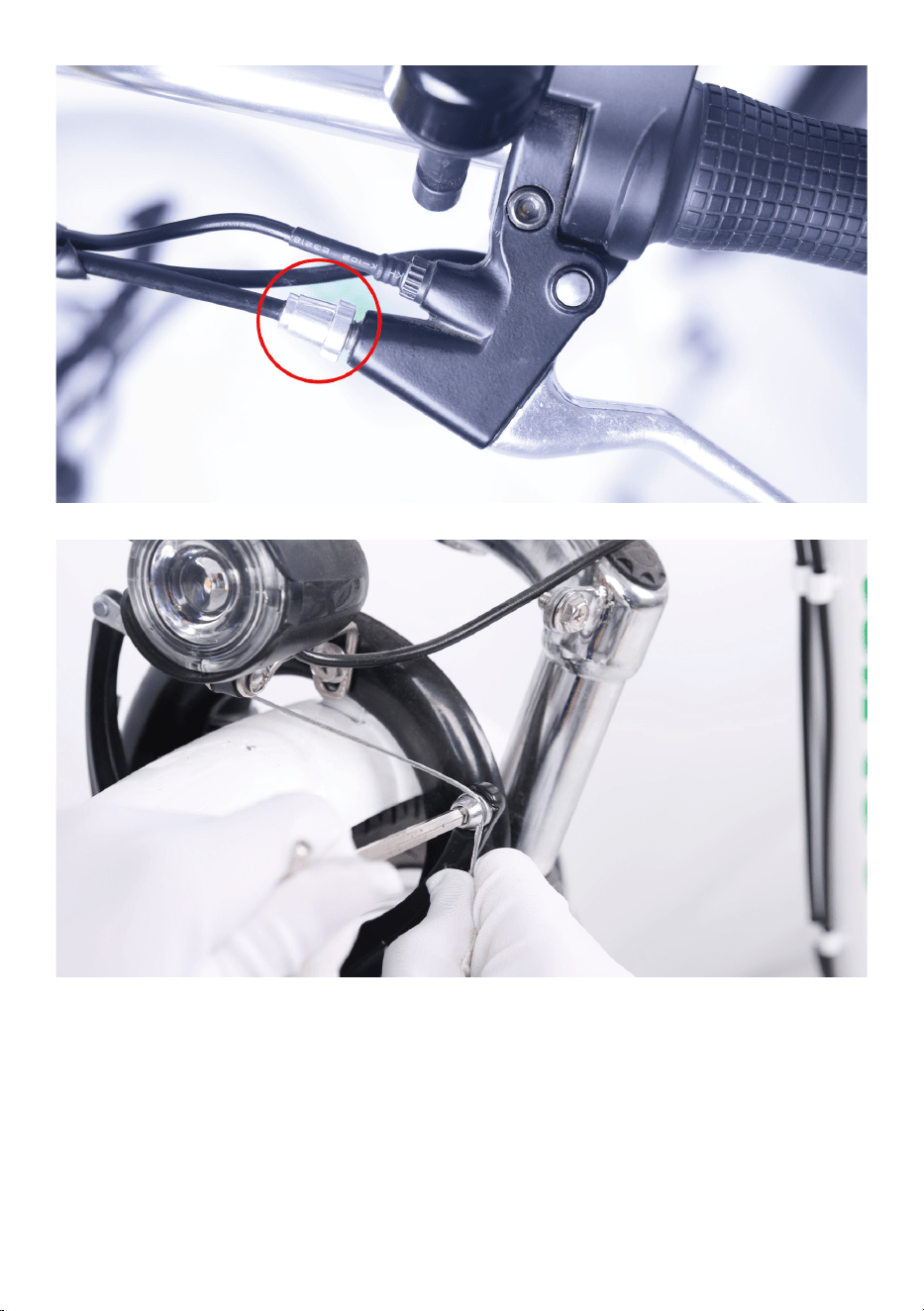
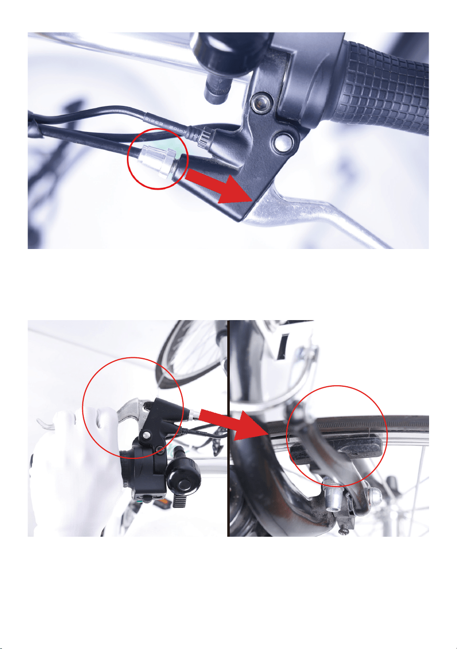
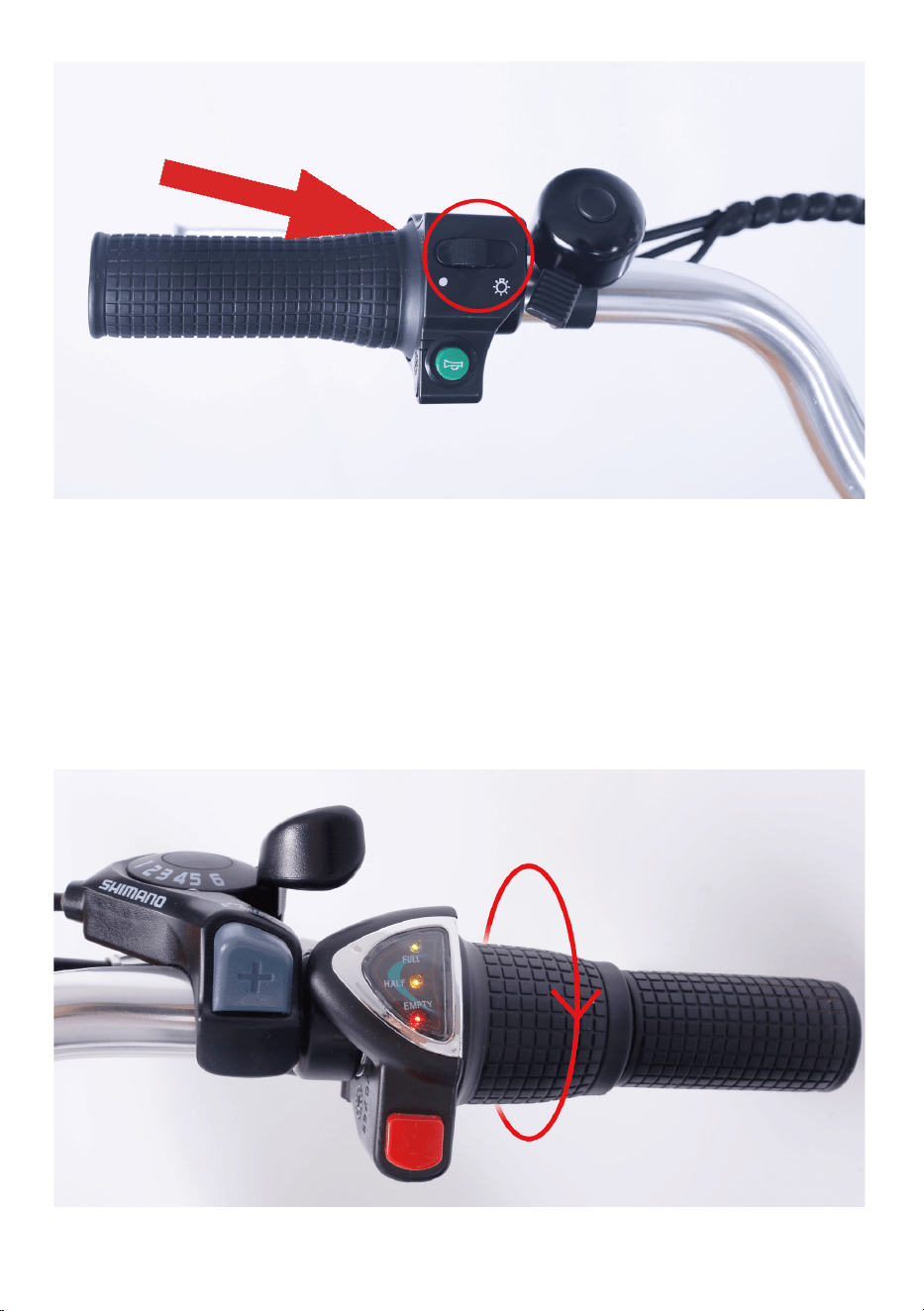
4.Turn on the headlight if needed or desired. Turn on the headlight by
sliding the light button to right. Turn on the headlight by sliding the light
button to left.
5.Begin riding carefully.⸺Hold handlebars and start pedaling on a flat
surface, in a low gear (1 or 2), most riders should be able to begin pedal-
ing the bike with pedal assist. You may also use the throttle to accelerate
and maintain your desired speed.
6.The throttle is used by slowly and carefully rotating the throttle back-
ward toward the rider. The more you twist, the more powerfully the
throttle will propel the bike forward. The throttle is active whenever the
bike is turned on. Do not use the throttle unless you are on the bike.
Do not use the throttle while dismounted. Avoid accidental application of
the throttle while dismounted; anytime you are moving the bike while
dismounted, ensure the bike is powered off to prevent accidental applica-
tion of the throttle.
7.Brake⸺Brake the bike by squeezing the brake lever (Notice: as a
safety feature applying either front or rear brake will disengage the
motor.)
8.Deactivate the pedal assistance system⸺Press the red button on
the right handlebar again.
9.Turn off the battery and remove the key when you park.

We recommend that you always wear protective gear when cycling such
as a helmet, gloves, elbow pads and goggles.
When riding, obey the same road laws as all other road vehicles as
applicable by law in your area.
Best to charge the battery during the day when someone is around.
Overnight charging is not recommended.
Before riding always carry out a through safety check each time. We
highly recommend that you read the instruction manual before your very
first ride.
It is the user’s responsibility to ensure a potential passenger on the
Nakto eblike is adequately experienced and healthy enough to ride
safely as a passenger. Serious injury or death can occur if passengers are
inexperienced or in poor health such that it impacts their ability to ride
as passengers safely.
Carrying baggage may reduce the control of your ebike.
Take extra care while riding in wet and sandy surface including decreas-
ing speed and increasing braking distances.
!
WARING

Trek Power Inc
Toll Free: 1-855-997-7297
E-mail: support@nakto.com
Website: www.nakto.com
Adress:1683 Sierra Madre,Placentia,CA 92870
ELECRTIC
BICYCLE

