
Installation Guide
Due to regular upgrades of systems and products, ZKTeco could not guarantee exact consistency between the
actual product and the written information in this manual.
Applicable Models: FHT3300, FHT3400
Version: 1.1
FHT3000 Series

Revision History
Revision Date Author
Description
V1.0
V1.1
05/10/2023
03/20/2024
Yang Kaijin
Yang Kaijin
Original Document.
Reviewer
The appearance of the device
have been changed.
1 Installation Requirements
1.
After installation, check the grounding wire, connectors, junctions of the connecting line, and moving
parts to ensure they are securely connected. Promptly tighten any loose nuts, screws, or fasteners to
prevent long-term gate failure.
4.
3.
Make sure the device's grounding wire is securely connected. Differentiate between high and low
voltage power setups to prevent potential harm to personal safety and unexpected incidents.
2.
Do not use the device outdoors or in wet, corrosive conditions to prevent damage from rain, moisture,
or corrosive materials. Only use it if the device is specifically rated as waterproof.
It is recommended that the device be installed on a level and solid floor. If the floor is uneven or not
strong enough to hold the device in place, resurface the floor or use a pedestal mount to alleviate the
change problem.
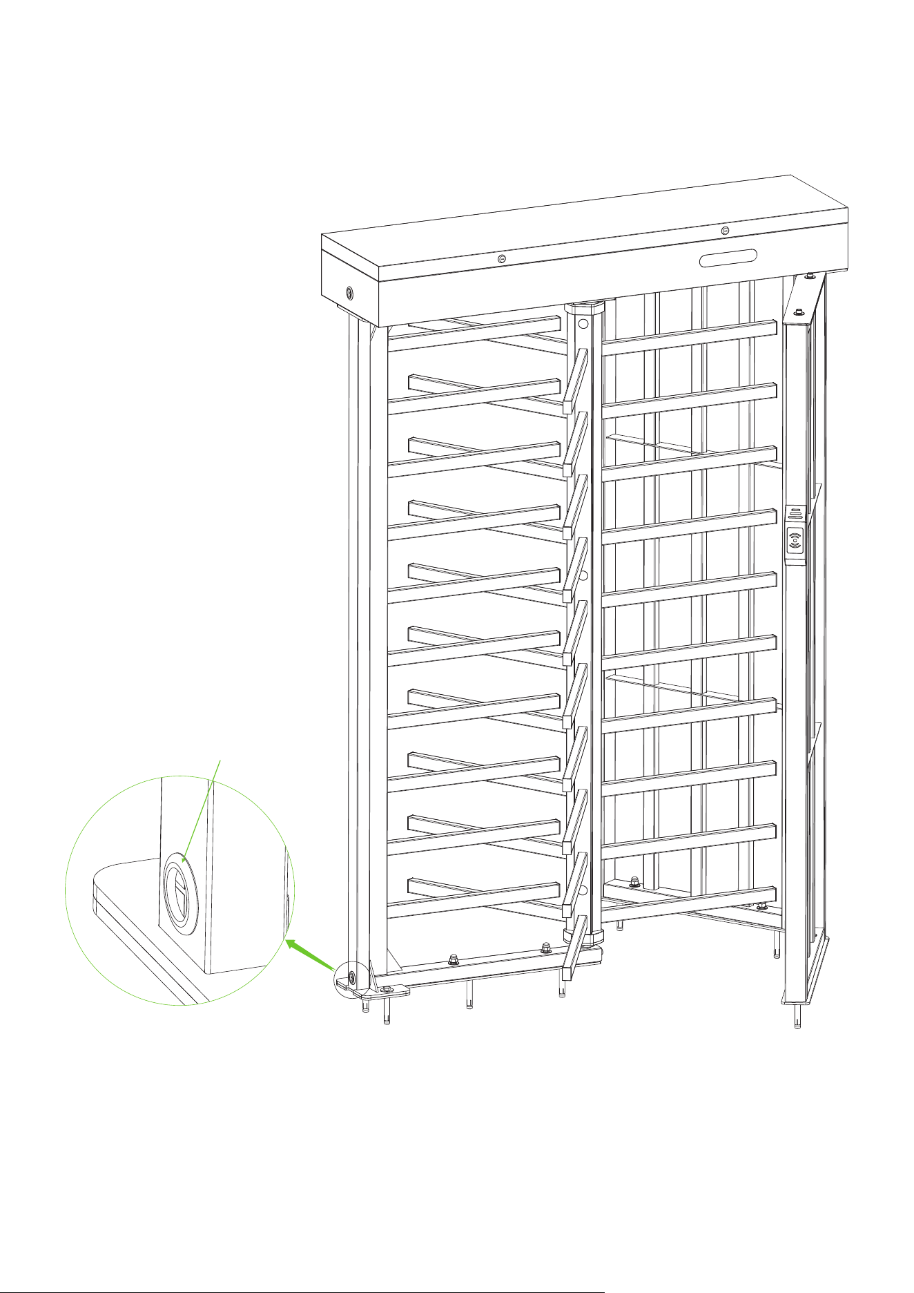
2 Installation FHT3300 Series
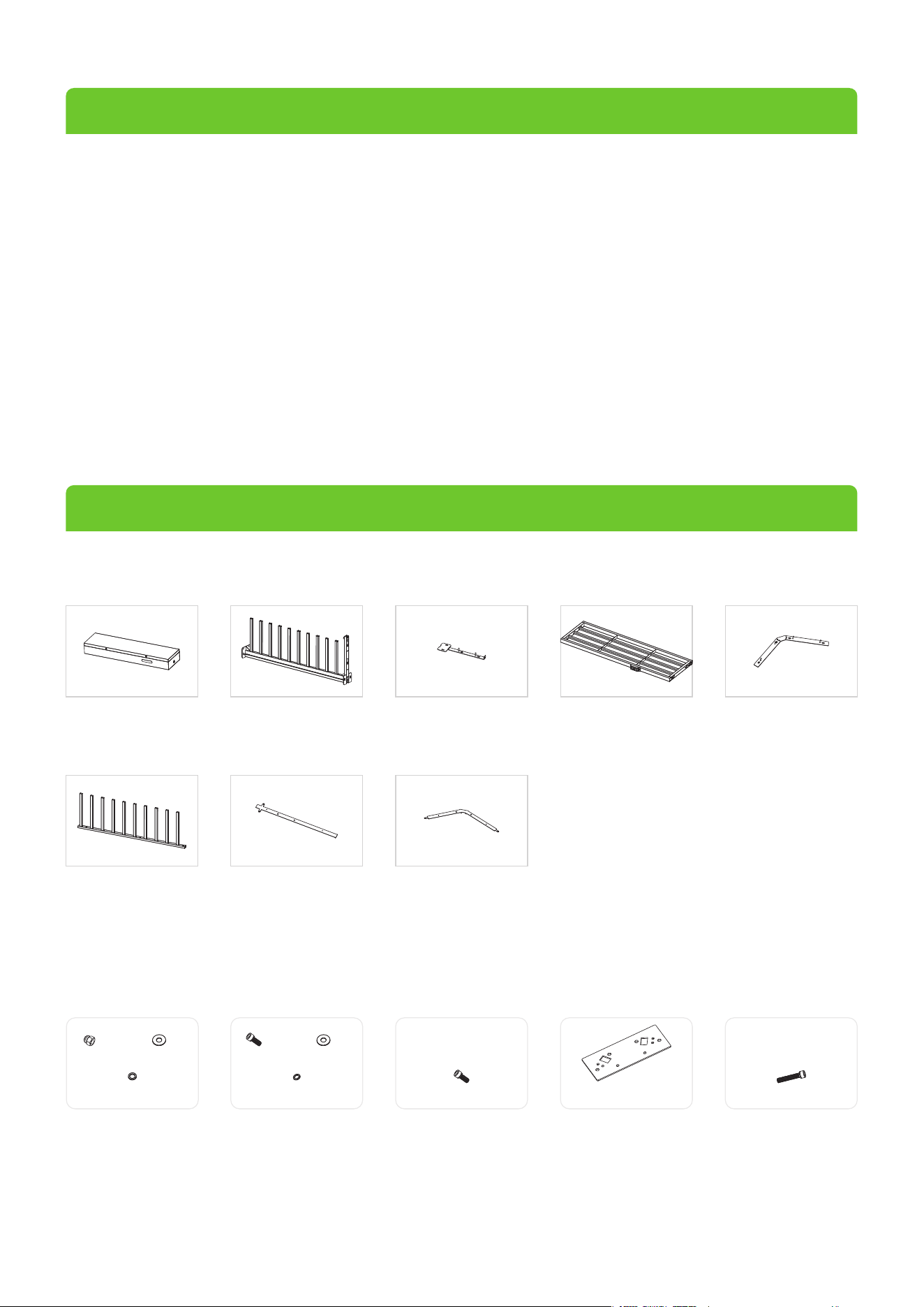
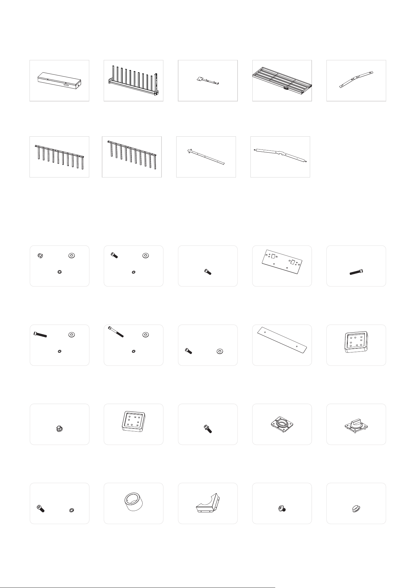
FHT3300 Series Component List
Mainboard
Controller Box
(Qty 1)
Stator Bar Frame
(Qty 1)
Passage Way Side Frame
(Qty 2)
Fixing Plate for
Stator Bar Frame
(Qty 1)
Fixing Plate for
Passage Way Side Frame
(Qty 1)
Rotor Barrier
(Qty 3)
Floor Mounting Plate A
(Qty 1)
Floor Mounting Plate B
(Qty 1)
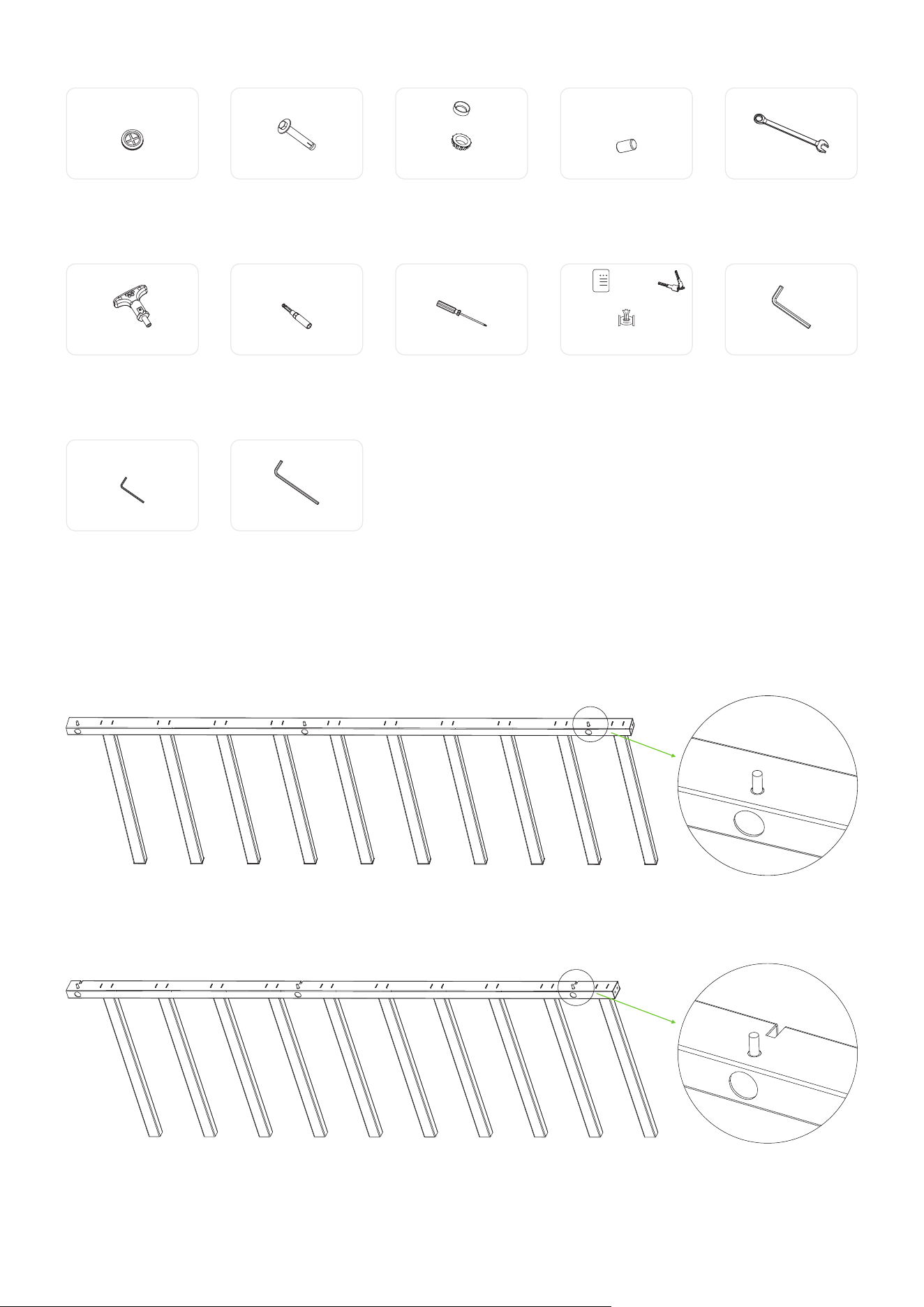
FHT3300 Series Accessory List
Accessory 1
Nut x6 Flat Washer x6
Spring Washer x6
Accessory 2
Screw x1 Flat Washer x1
Spring Washer x1
Accessory 3
Screw x4
Accessory 4
Top Plate x1
Accessory 5
Screw x6
1

Accessory 16
Screw x6 Spring Washer x6
Accessory 6
Accessory 11
Screw x2 Flat Washer x2
Spring Washer x2
Locknut x9
Accessory 7
Screw x2 Flat Washer x2
Spring Washer x2
Accessory 8
Screw x4 Flat Washer x4
Accessory 9
Top Plate A x2
Accessory 10
Fixation Block x3
Accessory 12
Connection Block x2
Accessory 13
Screw x12
Accessory 14
Bearing Seat x1
Accessory 15
Shaft Head x1
Accessory 17
Bearing x1
Accessory 18
Bearing Cover x2
Accessory 19
Screw x8
Accessory 20
Hole Plug x12
Accessory 27
Socket Spanner x1
Accessory 28
Screwdriver x1
Accessory 29
Maintenance x1 Key x1
Stainless Steel
Maintenance Wipes x1
Accessory 30
Hex Wrench x1
Accessory 31
Hex Wrench x1
Accessory 32
Hex Wrench x1
Accessory 21
Rubber Sheathing Coil x1
Accessory 22
Built-in Expansion Screw x8
Accessory 25
Wrench x1
Accessory 26
Ratchet Wrench x1
Accessory 23
Bottom Bearing A x1
Bottom Bearing B x1
Accessory 24
Spindle x2
2
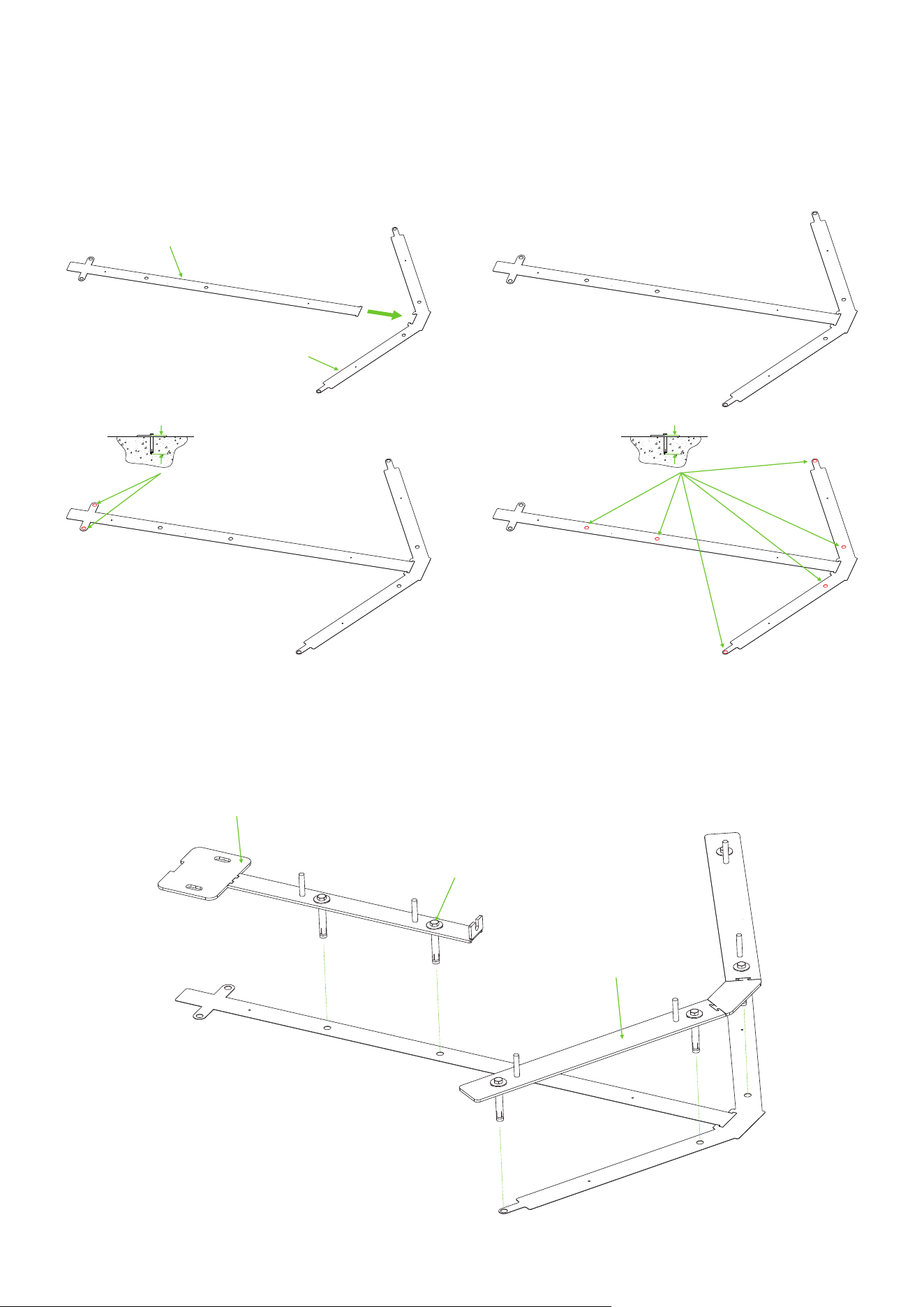
FHT3300 Series Installation Procedure
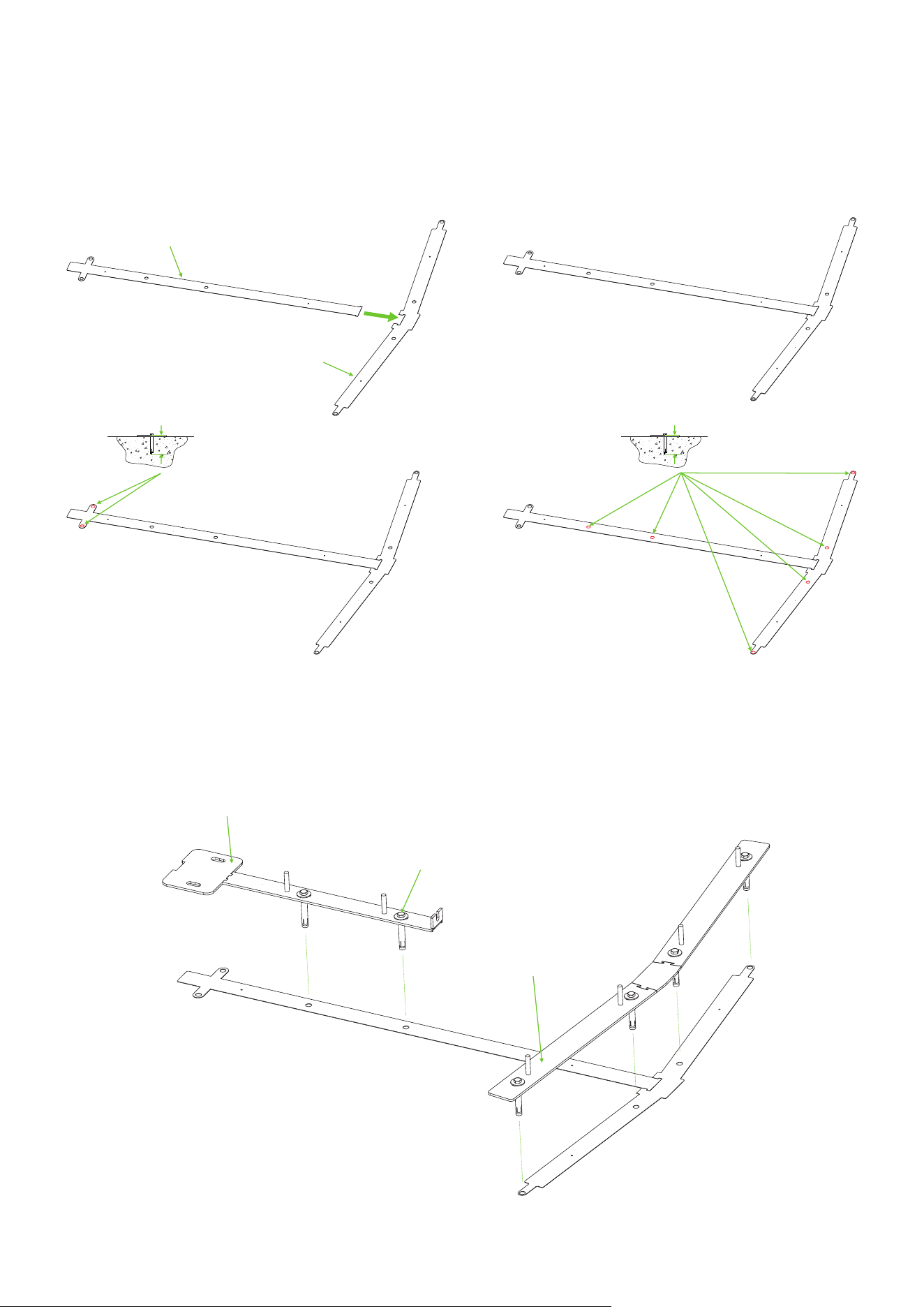
Connect Floor Mounting Plate A and Floor Mounting Plate B together and use an electric drill to drill
6 holes to a depth of 92cm and 2 holes to a depth of 84.8cm. As shown in the diagram below:
1.
Floor Mounting Plate A
Floor Mounting Plate B
84.8cm 92cm
① ②
④③
Fixing Plate for Stator Bar Frame
Fixing Plate for Passage Way Side Frame
Accessory 22 (Built-in Expansion Screw)
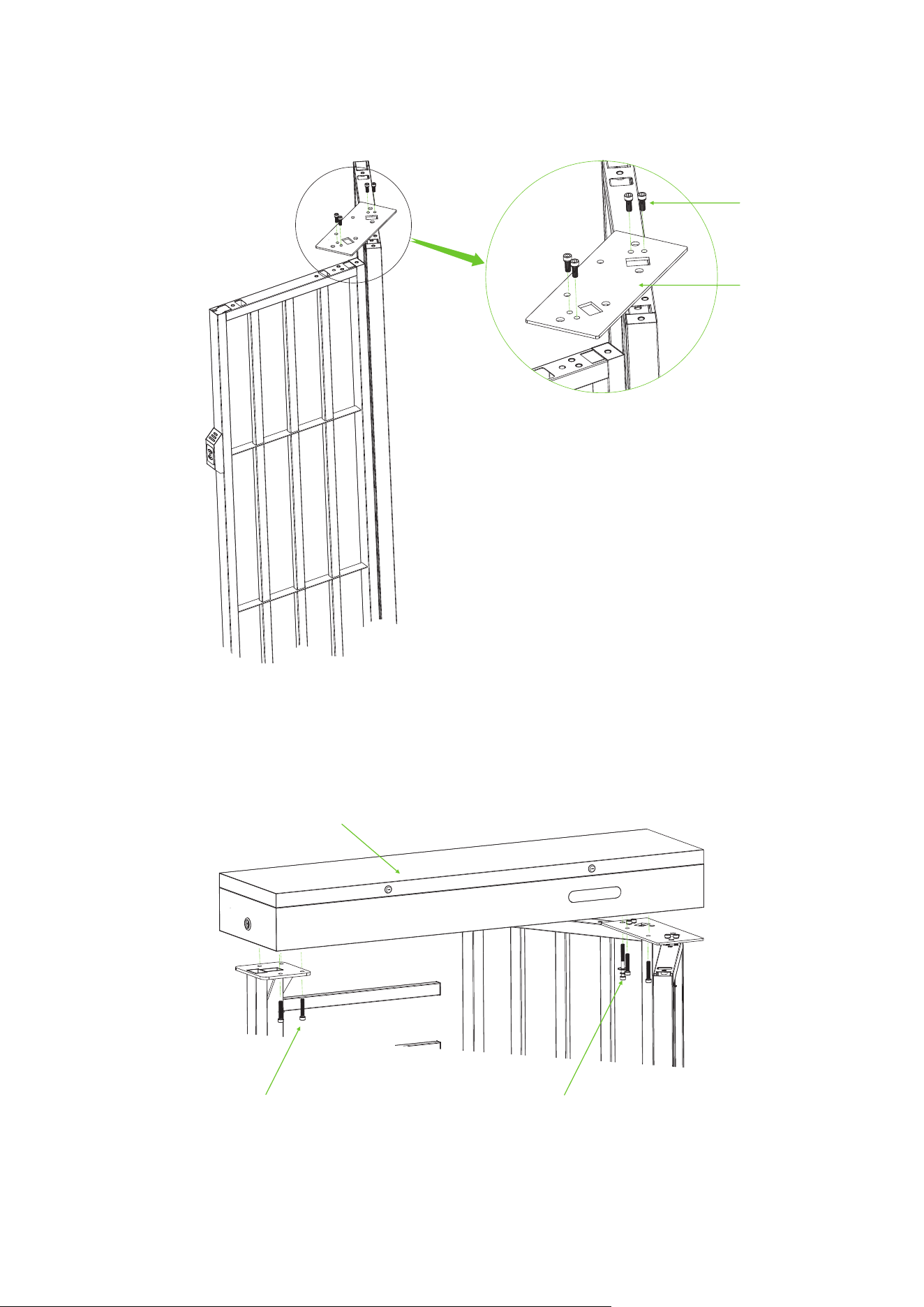
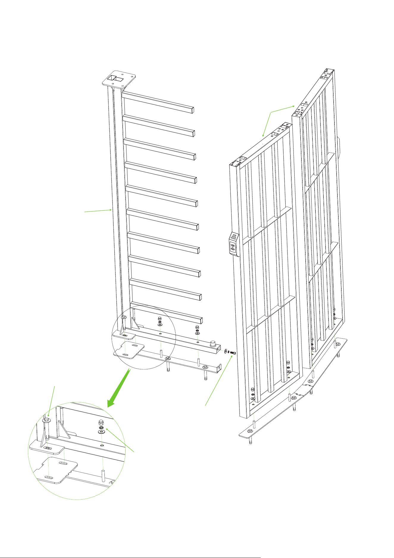
Install the Fixing Plate for Stator Bar Frame and Fixing Plate for Passage Way Side Frame on the
Floor Mounting Plate. Secure them in place using 6 Built-in Expansion Screws.
2.
3
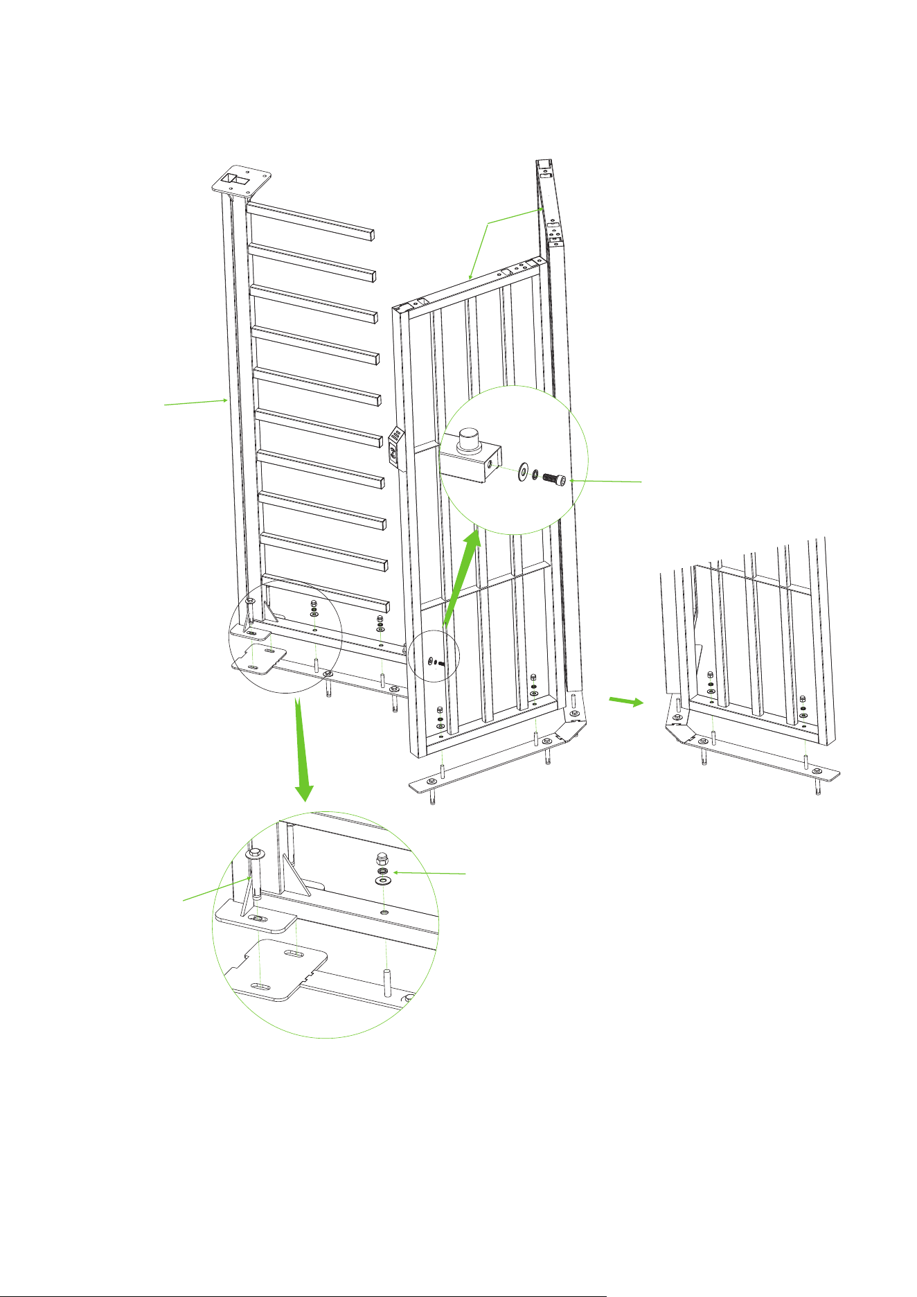
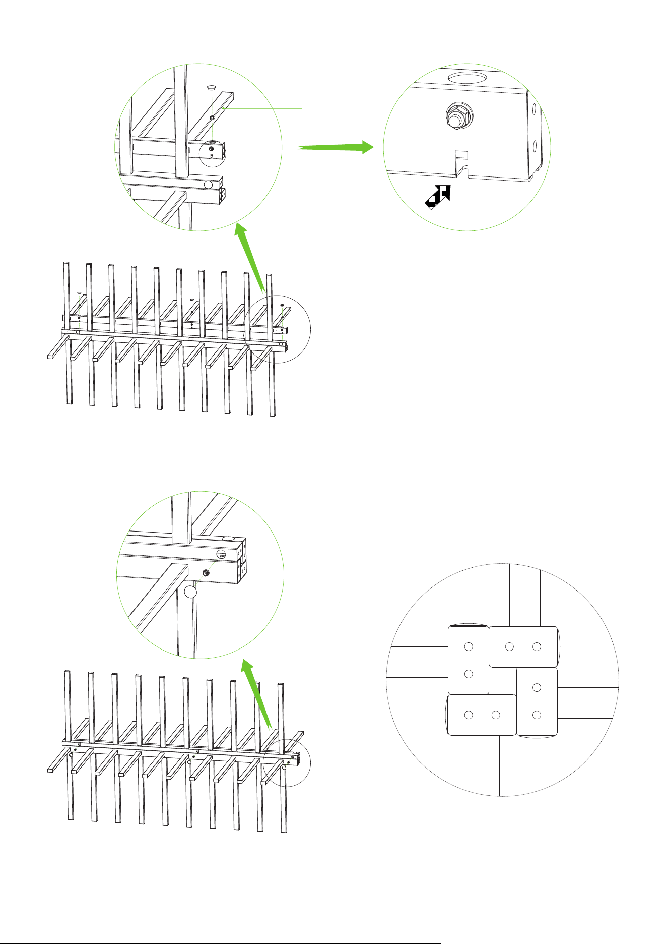
Attach the Stator Bar Frame and Passage Way Side Frame to the corresponding Fixing Plate respectively.
Secure them using 2 Built-in Expansion Screws, and Accessory 1 and Accessory 22.
3.
Stator Bar Frame
Passage Way
Side Frame
Accessory 1 (Nut x6 + Flat Washer x6 + Spring Washerx6)
Accessory 22
(Built-in Expansion Screw)
Accessory 2 (Screw x1 + Flat Washer x1
+ Spring Washerx1)
Flip
4
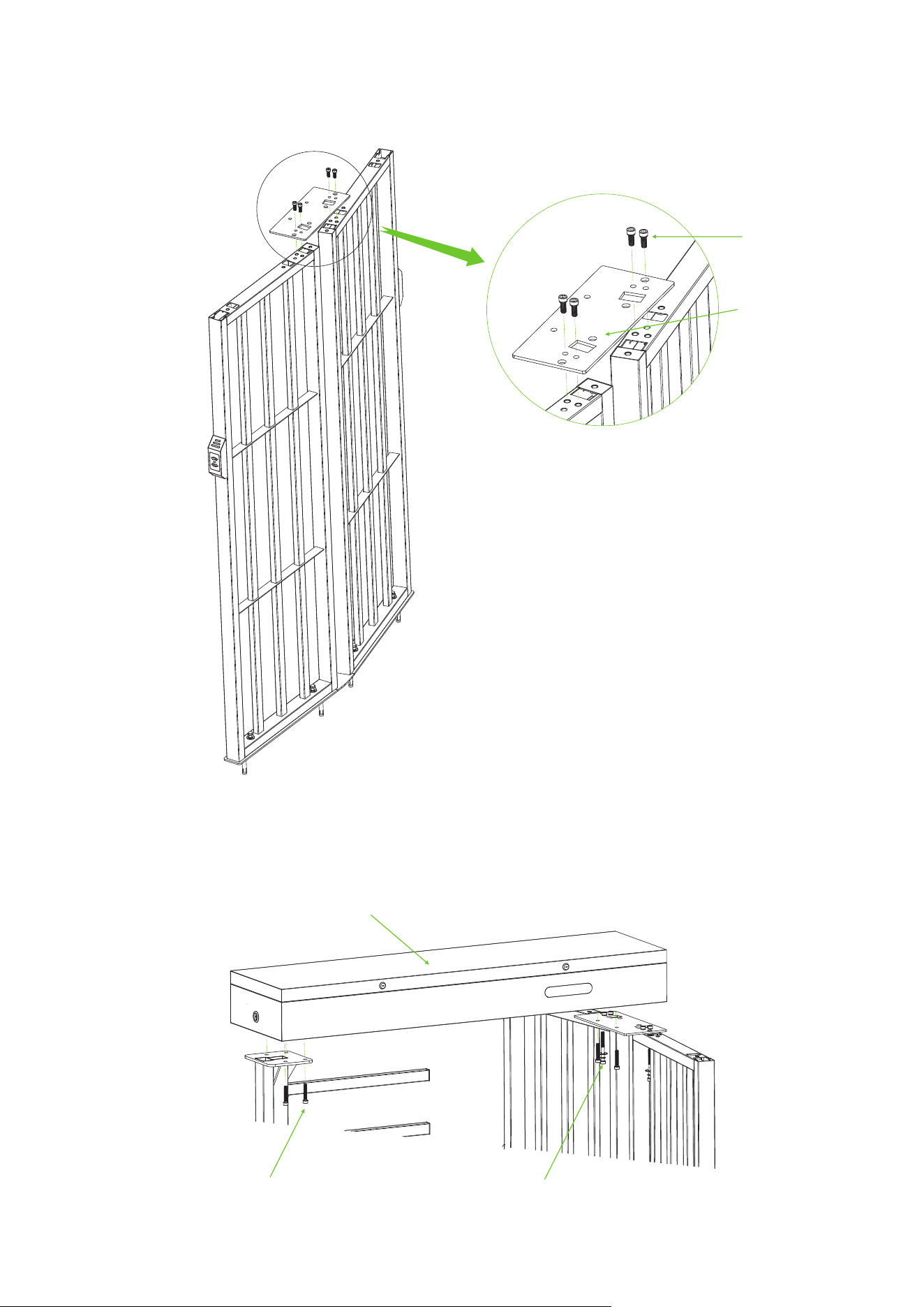
Attach Accessory 4 (Top Plate) to the top of the Passage Way Side Frame using the screws from
Accessory 3.
4.
Accessory 4 (Top Plate)
Accessory 3 (Screw x4)
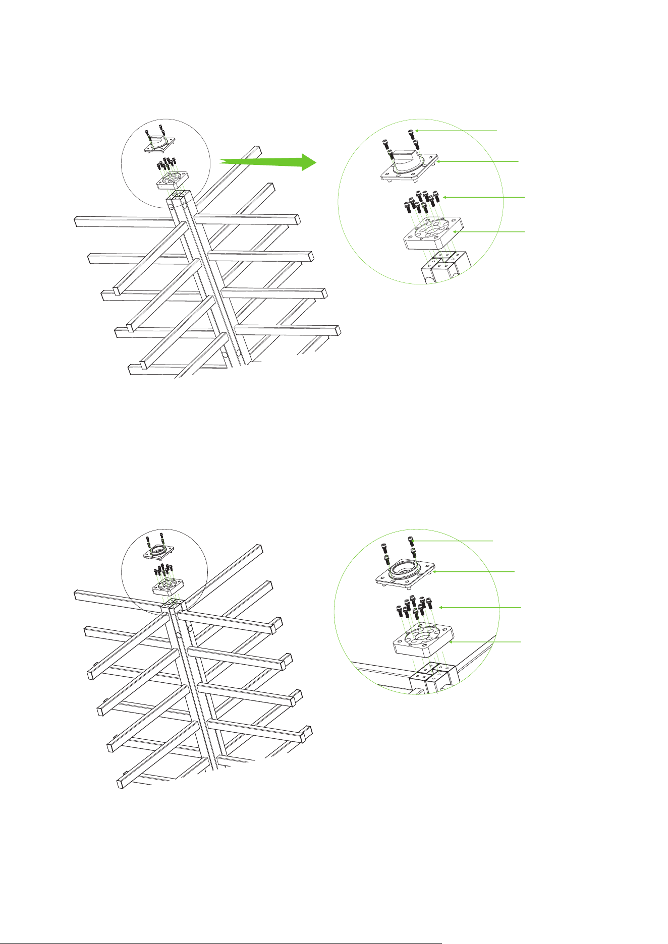
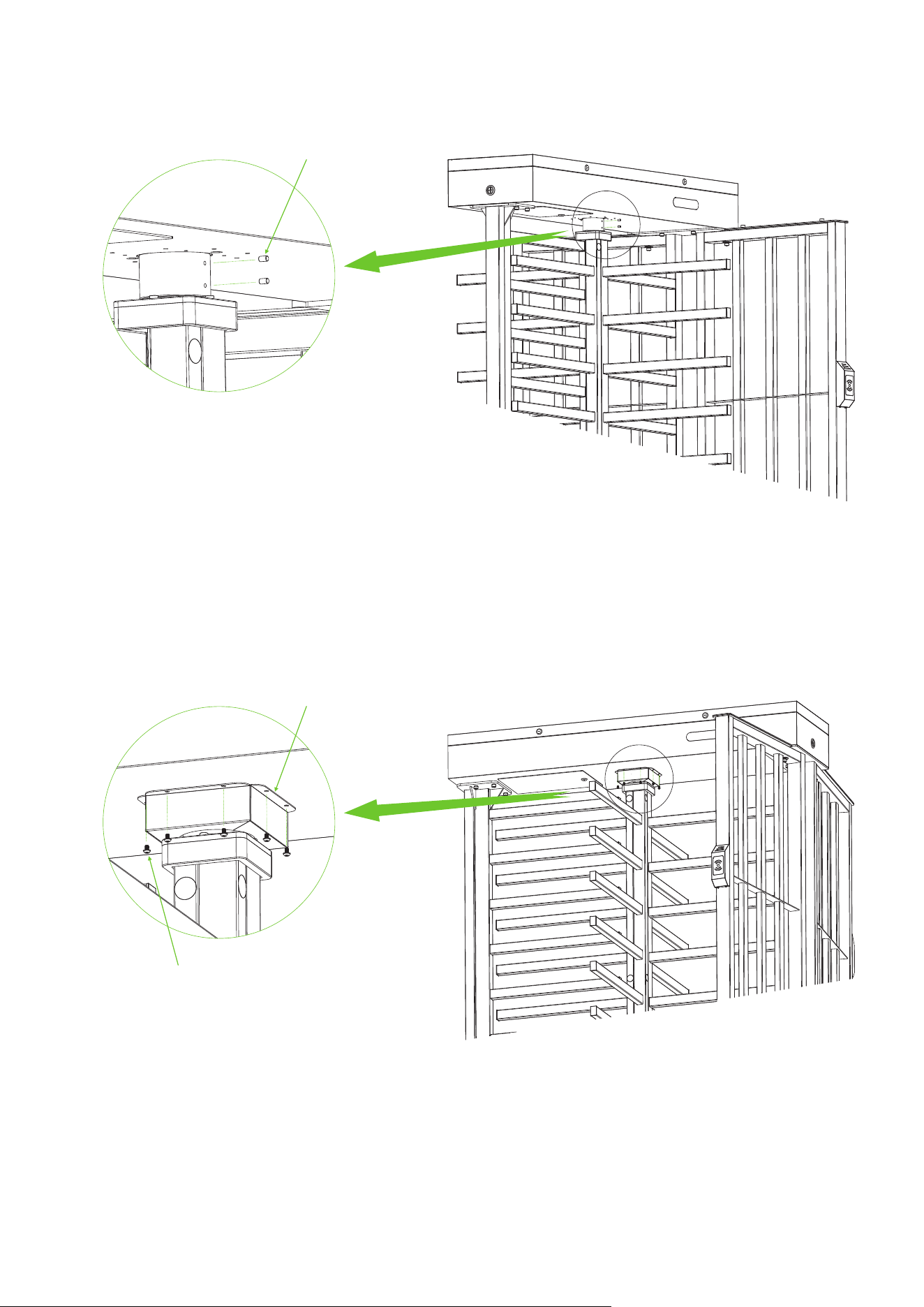
Mount the Mainboard Controller Box on top of the Stator Bar Frame and Passage Way Side Frame,
and secure with screws from Accessory 5 and Accessory 7.
5.
Accessory 5 (Screw x6)
Accessory 7 (Screw x2 + Flat Washer x2
+ Spring Washerx2)
Mainboard Controller Box
5
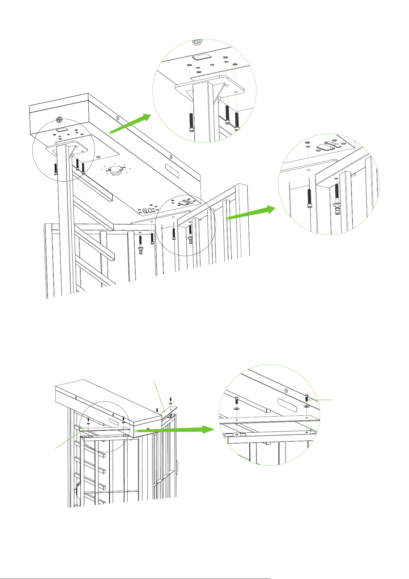
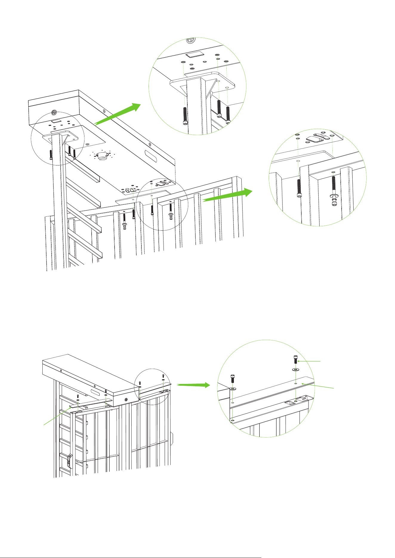
Attach the 2-sided Top Plate A to the top of the Passage Way Side Frame using the screws in
Accessory 8.
6.
Top Plate A
Top Plate A
Accessory 8
(Screw x4 + Flat Washer x4)
6
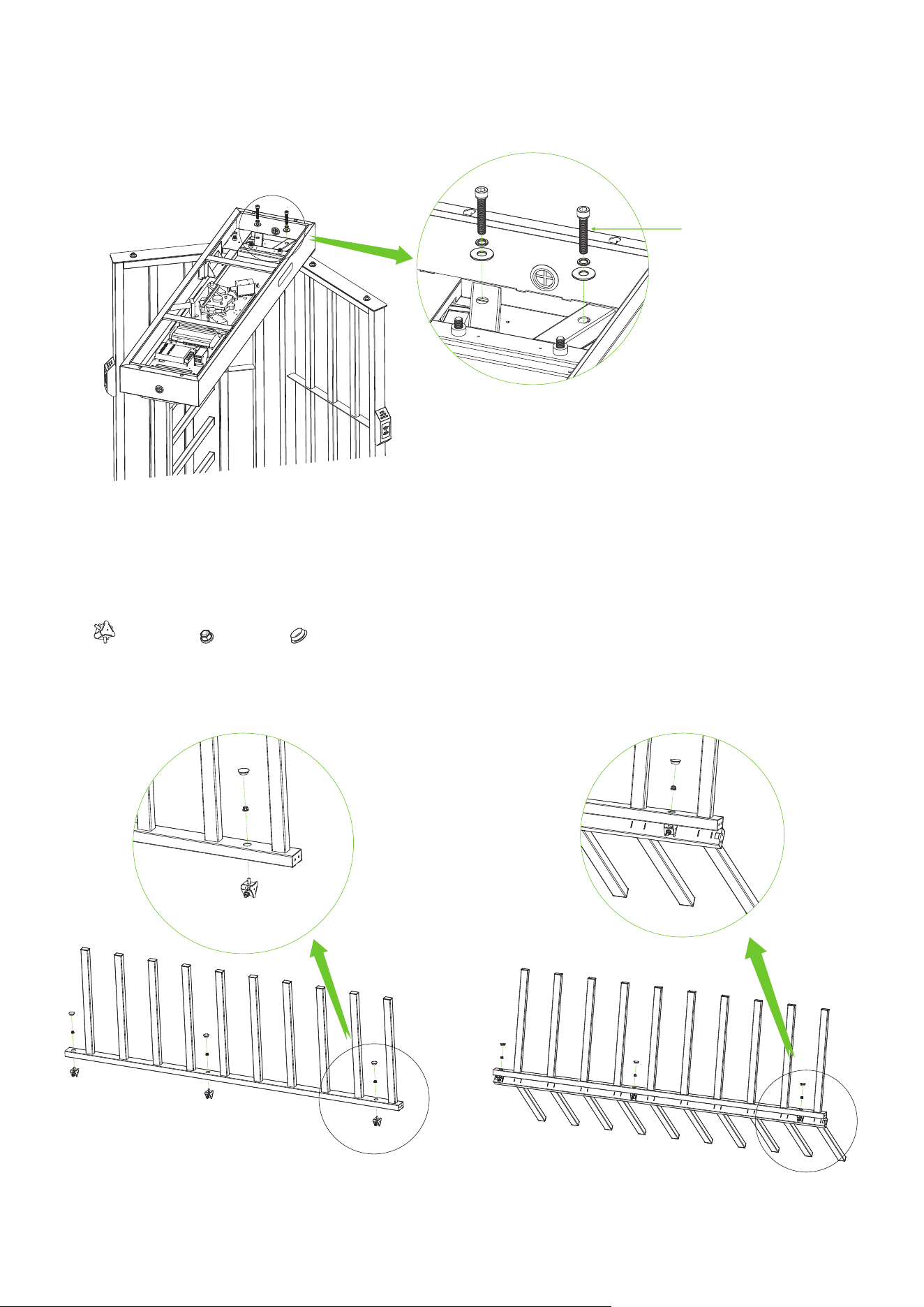
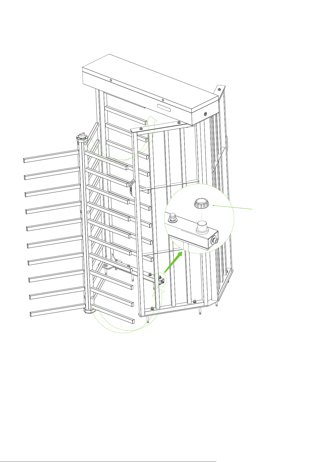
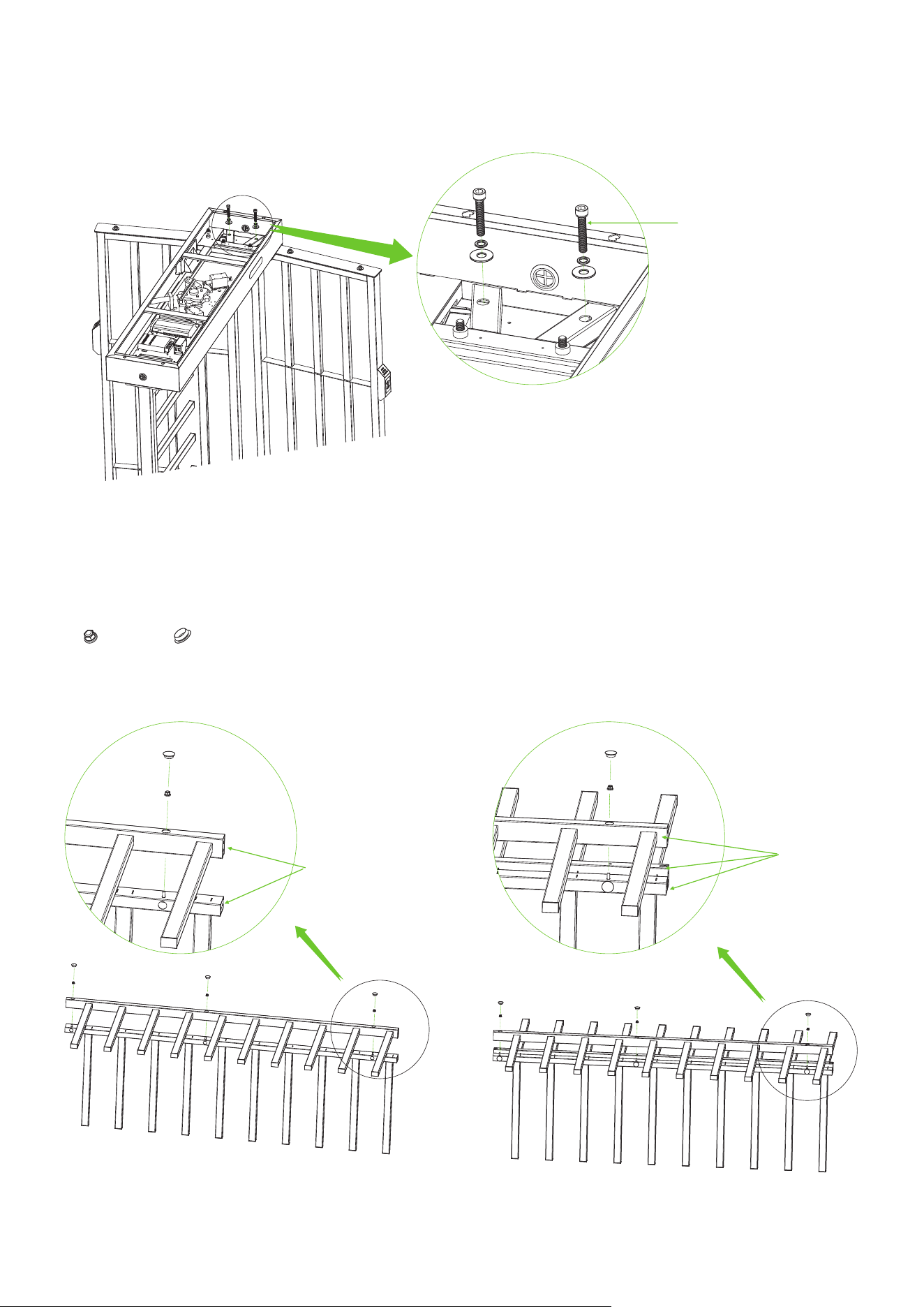
Open the door of the Mainboard Controller Box and secure the Mainboard Controller Box to the
Passage Way Side Frame using the screws provided in Accessory 6.
7.
Accessory 6 (Screw x2
+ Flat Washer x2 + Spring Washerx2)
Assemble the three Rotor Barriers together using the Fixation Block from Accessory 10, Locknut
from Accessory 11 and Hole Plug from Accessory 20.
8.
Fixation Block x3 Locknut x9 Hole Plug x9
① ②
7
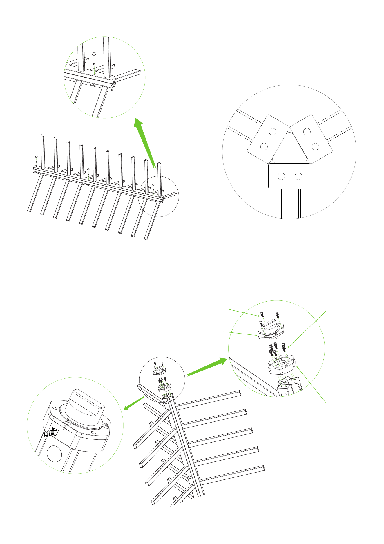
Top View
③
Install the Shaft Head and the Connection Block on top of Rotor Barriers, as installation is shown
below. Note: Pay attention to the direction.
9.
Accessory 16 (Screw x3 + Spring Washer x3)
Note the alignment
Accessory 13 (Screw x6)
Accessory 15 (Shaft Head)
Accessory 12 (Connection Block x1)
8
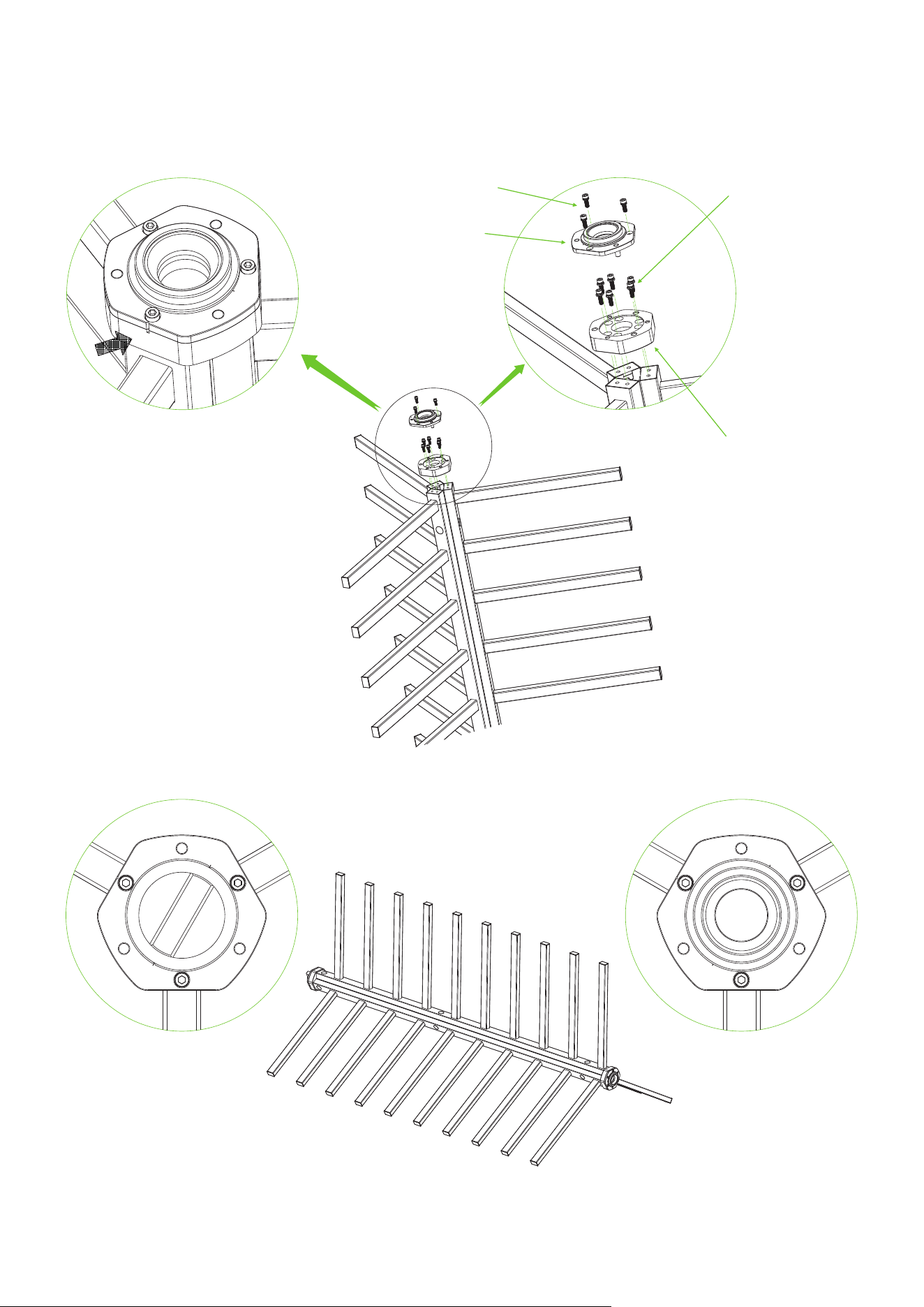
Install the Bearing Seat and the Connection Block on bottom of Rotor Barriers, as installation is
shown below. Note: Pay attention to the direction.
10.
Note the alignment
Accessory 13 (Screw x6)
Accessory 16 (Screw x3 + Spring Washer x3)
Accessory 14 (Bearing Seat)
Accessory 12 (Connection Block x1)
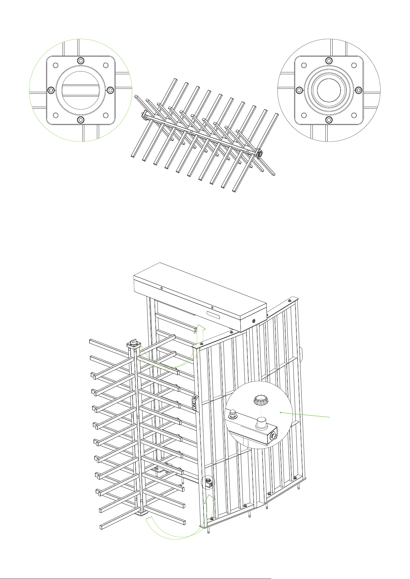
Top view of the top Top view of the bottom
Complete Overall Rotor Barriers
9
Place the Accessory 23 on the Stator Bar Frame, then install Complete Overall Rotor Barriers on the
Stator Bar Frame.
11.
Tilt Placement
②
①
Accessory 23
(Bottom Bearing A x1
+ Bottom Bearing B x1)
10
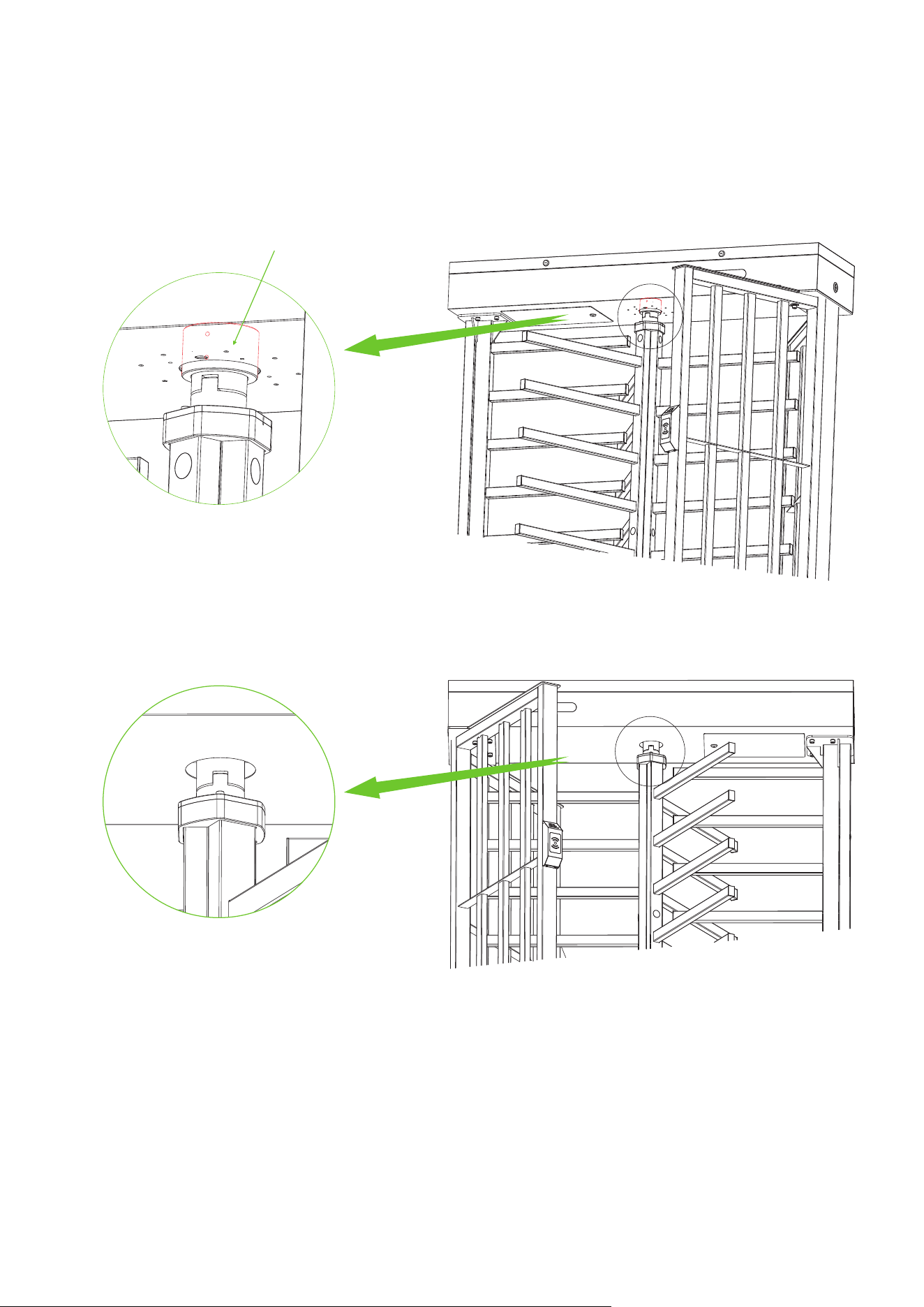
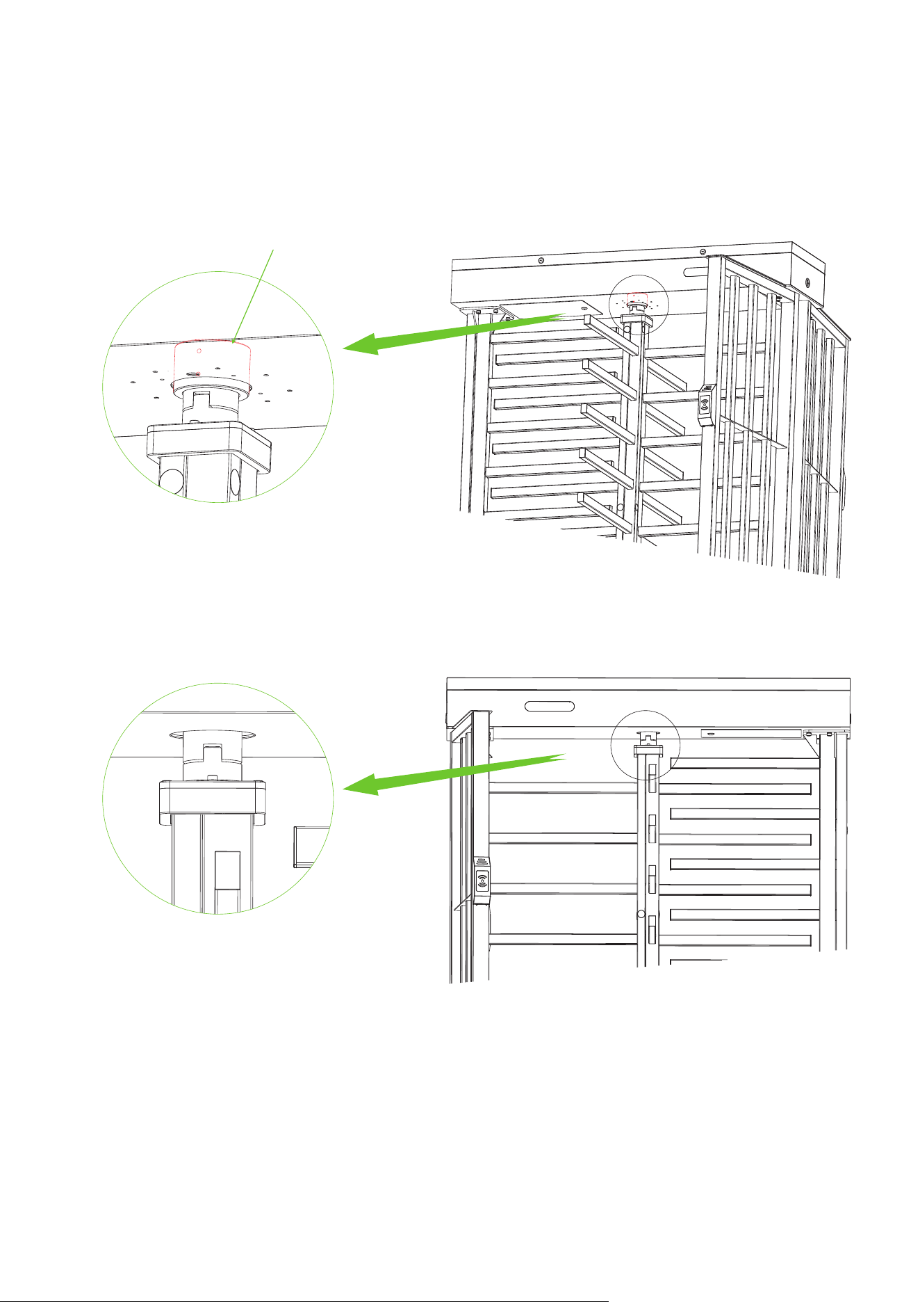
Before inserting the tops of the Complete Overall Rotor Barriers into the rotating parts on the
bottom of the Mainboard Controller Box, it is necessary to install the Accessory 17 on the rotating
parts on the bottom of the Mainboard Controller Box ( The bearing need to be pushed up), and then
insert the Complete Overall Rotor Barriers correctly under the Mainboard Controller Box. Note:
After putting in need to vertical.
12.
Accessory 17 ( Bearing x1 )
Note the vertical
11
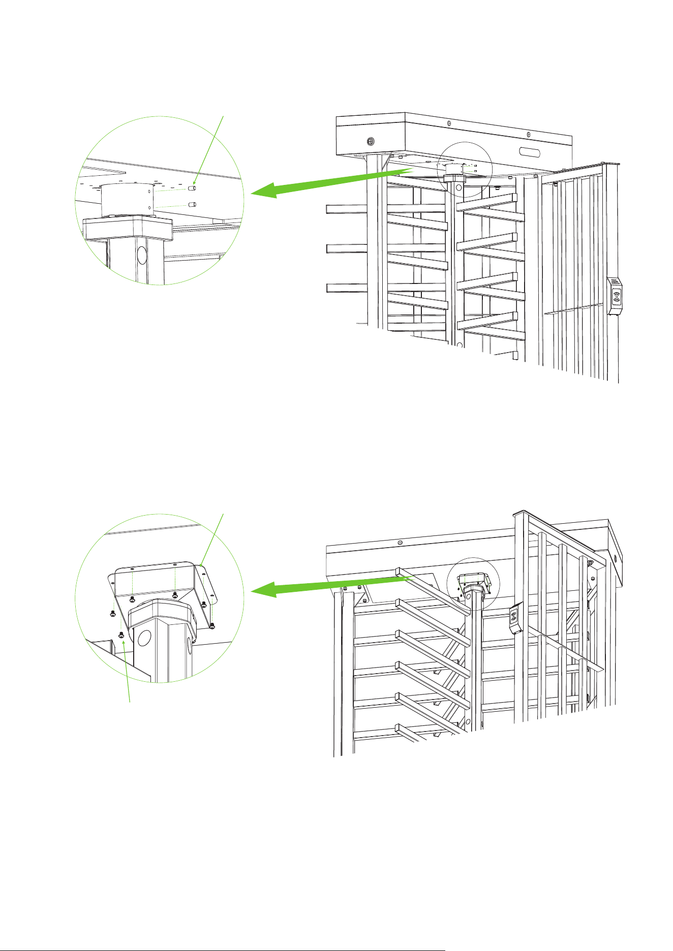
Use the Accessory 24 to secure the Complete Overall Rotor Barriers.
Use the Accessory 18 and the Accessory 19 to secure Complete Overall Rotor Barriers and
Accessory 17 to the bottom of the Mainboard Controller Box.
13.
14.
Accessory 24 ( Spindle x2 )
Accessory 18 ( Bearing Cover x2 )
Accessory 19 ( Screw x8 )
12
After the installation of FHT3300 series device is completed, inserted the Rubber Sheathing Coil into
the corresponding positions.
15.
Accessory 21 ( Rubber Sheathing Coil x1)
13
Rotor Barrier B
(Qty 1)
Floor Mounting Plate A
(Qty 1)
Floor Mounting Plate B
(Qty 1)
Rotor Barrier A
(Qty 3)
FHT3400 Series Component List
Mainframe Box
(Qty 1)
Stator Bar Frame
(Qty 1)
Passage Way Side Frame
(Qty 2)
Fixing Plate for
Stator Bar Frame
(Qty 1)
Fixing Plate for
Passage Way Side Frame
(Qty 1)
Accessory 16
Screw x8 Spring Washer x8
Accessory 6
Screw x2 Flat Washer x2
Spring Washer x2
Accessory 11
Locknut x12
Accessory 7
Screw x2 Flat Washer x2
Spring Washer x2
Accessory 12
Connection Block A x1
Accessory 9
Top Plate A x2
Accessory 14
Bearing Seat x1
Accessory 8
Screw x4 Flat Washer x4
Accessory 13
Screw x16
Accessory 17
Bearing x1
Accessory 18
Bearing Cover x2
Accessory 19
Screw x8
Accessory 20
Hole Plug x14
FHT3400 Series Accessory List
Accessory 1
Nut x6 Flat Washer x6
Spring Washer x6
Accessory 2
Screw x1 Flat Washer x1
Spring Washer x1
Accessory 3
Screw x4
Accessory 4
Top Plate x1
Accessory 5
Screw x6
Accessory 10
Connection Block Bx1
Accessory 15
Shaft Head x1
14
Accessory 27
Socket Spanner x1
Accessory 28
Screwdriver x1
Accessory 29
Maintenance x1 Key x2
Stainless Steel
Maintenance Wipes x2
Accessory 30
Hex Wrench x1
Accessory 31
Hex Wrench x1
Accessory 32
Hex Wrench x1
Accessory 26
Ratchet Wrench x1
Accessory 21
Rubber Sheathing Coil x1
Accessory 22
Built-in Expansion Screw x8
Accessory 25
Wrench x1
Accessory 23
Bottom Bearing A x1
Bottom Bearing B x1
Accessory 24
Spindle x2
15
Note:
Notched
Chipped
Rotor Barrier A
Rotor Barrier B
FHT3400 Series Installation Procedure
Connect Floor Mounting Plate A and Floor Mounting Plate B together and use an electric drill to drill
6 holes to a depth of 92cm and 2 holes to a depth of 84.8cm. As shown in the diagram below:
1.
Floor Mounting Plate A
Floor Mounting Plate B
84.8cm 92cm
① ②
④③
Install the Fixing Plate for Stator Bar Frame and Fixing Plate for Passage Way Side Frame on the
Floor Mounting Plate. Secure them using 6 Built-in Expansion Screws.
2.
Fixing Plate for Stator Bar Frame
Accessory 22 (Built-in Expansion Screw)
Fixing Plate for Passage Way Side Frame
16
Attach the Stator Bar Frame and Passage Way Side Frame to the corresponding Fixing Plate respectively.
Secure them using 2 Built-in Expansion Screws, and Accessory 1 and Accessory 22.
3.
Accessory 1 (Nut x6 + Flat Washer x6 + Spring Washerx6)
Accessory 22
(Built-in Expansion Screw)
Accessory 2 (Screw x1 + Flat Washer x1
+ Spring Washerx1)
Stator Bar Frame
Passage Way
Side Frame
17
Attach Accessory 4 (Top Plate) to the top of the Passage Way Side Frame using the screws from
Accessory 3.
4.
Mount the Mainboard Controller Box on top of the Stator Bar Frame and Passage Way Side Frame,
and secure with screws from Accessory 5 and Accessory 7.
5.
Accessory 3 (Screw x4)
Accessory 4 (Top Plate)
Accessory 5 (Screw x6)
Mainboard Controller Box
Accessory 7 (Screw x2 + Flat Washer x2
+ Spring Washerx2)
18
Top Plate A
Attach the 2-sided Top Plate A to the top of the Passage Way Side Frame using the screws in
Accessory 8.
6.
Top Plate A
Accessory 8
(Screw x4 + Flat Washer x4)
19
Open the door of the Mainboard Controller Box and secure the Mainboard Controller Box to the
Passage Way Side Frame using the screws in Accessory 6.
7.
Accessory 6 (Screw x2
+ Flat Washer x2 + Spring Washerx2)
Assemble the four Rotor Barriers together using the Locknut from Accessory 11 and the Hole Plug
from Accessory 20.
8.
Locknut x12 Hole Plug x12
① ②
20
Rotor Barrier A
Rotor Barrier A
Top View
③
④
21
Rotor Barrier B
Install the Shaft Head and the Connection Block A on top of Rotor Barriers, as installation is shown
below. Note: Pay attention to the direction.
9.
Accessory 16
(Screw x4 + Spring Washer x4)
Accessory 13 (Screw x8)
Accessory 15 (Shaft Head)
Accessory 12
(Connection Block A x1)
Install the Bearing Seat and the Connection Block B on bottom of Rotor Barriers, as installation is
shown below. Note: Pay attention to the direction.
10.
Accessory 14 (Bearing Seat)
Accessory 16
(Screw x4 + Spring Washer x4)
Accessory 13 (Screw x8)
Accessory 10
(Connection Block B x1)
22
Top view of the top Top view of the bottom
Complete Overall Rotor Barriers
Place the Accessory 23 to the Stator Bar Frame, then install Complete Overall Rotor Barriers on the
Stator Bar Frame.
11.
Tilt Placement
②
①
Accessory 23
(Bottom Bearing A x1
+ Bottom Bearing B x1)
23
Before inserting the tops of the Complete Overall Rotor Barriers into the rotating parts on the
bottom of the Mainboard Controller Box, it is necessary to install the Accessory 17 on the rotating
parts on the bottom of the Mainboard Controller Box ( The bearing need to be pushed up), and then
insert the Complete Overall Rotor Barriers correctly under the Mainboard Controller Box. Note:
After putting in need to vertical.
12.
Accessory 17 ( Bearing x1 )
Note the vertical
24
Use the Accessory 24 to secure the Complete Overall Rotor Barriers.
Use the Accessory 18 and the Accessory 19 to secure Complete Overall Rotor Barriers and
Accessory 17 to the bottom of the Mainboard Controller Box.
13.
14.
Accessory 24 ( Spindle x2 )
Accessory 18 ( Bearing Cover x2 )
Accessory 19 ( Screw x8 )
25
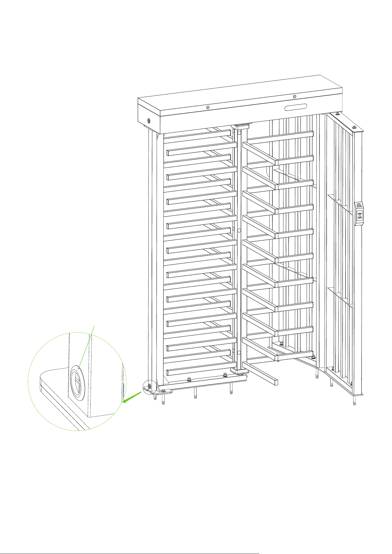
Accessory 21 ( Rubber Sheathing Coil x1)
After the installation of FHT3300 series device is completed, inserted the Rubber Sheathing Coil into
the corresponding positions.
15.
26
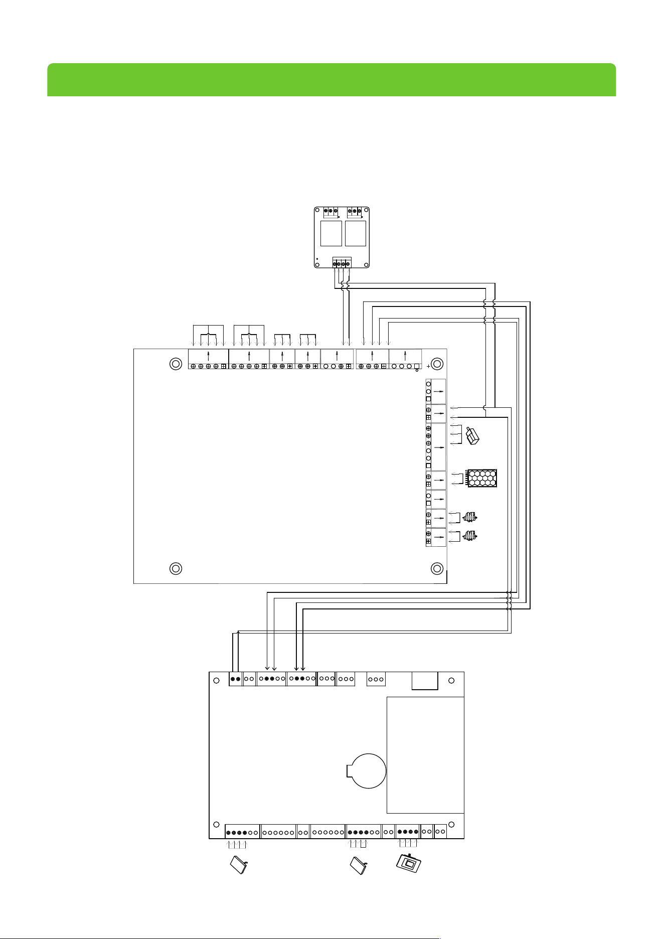
5 Wiring Diagra
After installation of the device, open the mainbox controller to connect power wire and reader. Remove the reader
and power cord from both sides of the column and connect to the corresponding interface.
m
L
-sole
n
oid
R-solenoid
P
r
o
ximit
y
S
wi
tc
h
2
4V
DC
P
owe
r
Supply
NO
C
OM
NO
C
OM
L
ock1
12V
GND
RS485
W
iegand
Access Control
L
ock2
K1
K2
485B
GND
485A
COM
GND
+24V
GND
GND
12V
NO
COM
NC
GND
COM
COM
DOW
L1G
+12V
L1R
NO
12V
COM
NC
12V
GL
RX
GR
L2G
+12V
L2R
K1
K2
ALARM
12VOUT
VCC
GND
GND
SEN
AUX
24VIN
GND
V2RV1L
UP
L
ef
t Mode light
R
igh
t M
ode light
Wiegand
NO2 NC2
COM2
COM1N01
IN2IN1
DC-
DC+
NC1
C
ontr
ol boar
d
L
ef
t Indicator ligh
t
R
igh
t I
ndicat
or light
R
igh
t Coun
L
ef
t C
ount
er
ter
27

ZKTeco Industrial Park, No. 32, Industrial Road,
Tangxia Town, Dongguan, China.
Phone : +86 769 - 82109991
Fax : +86 755 - 89602394
www.zkteco.com
Copyright © 2025 ZKTECO CO., LTD. All Rights Reserved.