
SERVICE MANUAL
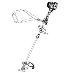
26cc 2-Cycle Brush Cutter
NPTBSP2609A
Read all safety rules and instructions carefully before servicing this tool.
601 Regent Park Court Greenville, SC 29607, 1-866-384-8432

2
Section Page
CONTENTS
CONTENTS 2
SPECIFICATIONS 3-4
GENERAL SAFETY RULES 5
PARTS AND FEATURES 6-11
WIRING DIAGRAM AND MANAGEMENT 12
GENERAL TROUBLESHOOTING 13-21
AIR & FUEL SYSTEM 22-29
THROTTLE AND STARTER SYSTEM 30-34
NOPULL™ STARTER SYSTEM 35-38
26CC 2-CYCLE ENGINE 39
GEAR HEAD AND BRUSH CUTTER BLADE 40
MANUFACTURER'S WARRANTY AND CONTACT 41

3
SPECIFICATIONS
TORQUE SPECIFICATIONS
Engine Size 2-Stroke / Full Crank
Engine Displacement Claimed / Rated 26cc / 25.4cm
3
Ignition Capacitor Discharge Ignition (CDI)
Carburetor All Position Diaphragm Type With Primer Bulb
Air Filter Foam (Dry)
Engine Shut Off Auto-Reset
Throttle Control Variable Speed Trigger
Fuel / Oil Ratio 40 : 1
Fuel Tank Capacity 400 ml
Spark Plug Champion RCJ6Y
Rotor Air Gap 0.012”-0.015” (0.30-0.40 mm)
Spark Plug Gap 0.026” (0.65 mm)
Run Time on Full Tank 30 Minutes
UNIT SPECIFICATIONS
Engine
Fuel System
General
Application Description
Torque Torque
(IN.LBS) (N.m)
Crankcase
Apply a thermostable screw-thread glue onto the 4
screws (M5X30) and then x the crankcase cover.
53-62 6-7
Cylinder to crankcase
Apply a thermostable screw-thread glue onto the 4
screws (M5X20) and then tighten the screws securing
the cylinder to crankcase.
53-62 6-7
Spark plug to cylinder
Pre-screw the spark plug to the cylinder, and then
tighten with a torque spanner.
115-137 13-15.5
Carburetor mount to
cylinder
Apply a thermostable screw-thread glue onto the 2
screws (M5X20) and tighten the screws securing the
carburetor mount to the cylinder.
35-44 4-5

4
SPECIFICATIONS
Flywheel to crankshaft
Apply a thermostable screw-thread glue onto the
crankshaft thread. Pre-screw the ange hexagon nut
(M8) and then tighten.
89-133 10-15
Clutch to ywheel
Slide the corrugated washers onto the clutch bolts
(M6X21.5). Apply a thermostable screw-thread glue
onto the bolt thread head section. Install the bolts into
the clutch and tighten the bolts securing the clutch to
ywheel.
71-89 8-10
Ignition coil to cylinder
Put the 2 screws (M5X20) through the ignition coil
and two spacers respectively. Apply a thermostable
screw-thread glue into the cylinder holes and then pre-
screw the 2 screws (M5X20). Insert a feeler gauge
of 0.014 in. (0.35mm) between the ywheel and the
ignition coil. Press down the ignition coil ush against
the feeler gauge. Tighten the screws with a torque
spanner securing the ignition coil. Remove the feeler
gauge.
27-35 3-4
Mufer to crankcase
Put the 2 bolts (M5X50) through the mufer assembly.
Apply a thermostable screw-thread glue onto the 2
bolts and secure the mufer to the crankcase using
the torque wrench.
62-71 7-8
Apply a thermostable screw-thread glue onto the
head section of 1 screw (M5X10). Pass the screw
through the positioning hole on the mufer assembly
holder and tighten the screw securing the mufer to
crankcase.
62-71 7-8
Pawl assembly to
crankshaft
Apply a thermostable screw-thread glue onto the
crankshaft thread. Pre-screw the pawl assembly to
crankshaft, and then tighten using the torque wrench.
62-80 7-9
Air lter base to
carburetor
Pre-screw the nuts (M5) with washers, and then
tighten using the pneumatic tool.
27-35 3-4
Fuel tank bracket to
crankcase
Apply a thermostable screw-thread glue onto the
screw (M5X10) and pass it through the hole on fuel
tank bracket. Tighten the screw securing the fuel tank
bracket to crankcase.
27-35 3-4
Fuel tank to crankcase
Apply a thermostable screw-thread glue onto the
screw (M5X12). Pass it through the fuel tank hole.
Tighten the screw securing the fuel tank to crankcase.
27-35 3-4
Cylinder pressure plate
Apply a thermostable screw-thread glue onto the
screw (M5X10). Pass the screw through the cylinder
pressure plate hole and then tighten it onto the
cylinder.
27-35 3-4
Electric starter
assembly to crankcase
Align the 2 screw holes on the electric starter
assembly with the screw holes on crankcase. Tighten
the 2 screws (M5X60) securing the electric starter
assembly to crankcase.
27-35 3-4
Rear engine cover
assembly
Tighten the 2 screws (ST3.9X30F) to secure the rear
engine cover.
12-13 1.3-1.5

5
SPECIFICATIONS
Flywheel cover to
crankcase
Apply a thermostable screw-thread glue into the two
holes on crankcase. Tighten the 2 screws (M5X15)
securing the ywheel cover to crankcase.
53-64 6-7.2
Lower engine cover
assembly
Place the lower engine cover onto crankcase. Tighten
the 3 screws (1*ST3.9X8, 2*M5X10) securing the
lower engine cover.
10-12
1.1-1.3 (for
1*ST3.9X8)
27-35
3-4 (for
2*M5X10)
Upper engine cover
assembly
Tighten the 3 screws (M5X35) securing the upper
engine cover.
27-35 3-4
Spark plug cover to
upper engine cover
Tighten the screw (M5X10) securing the spark plug
cover to upper engine cover.
27-35 3-4
Lower engine cover to
upper engine cover
Tighten the screw (ST3.9X12) to secure the upper and
lower engine covers (on mufer side).
10-12 1.1-1.3
Right handle cover to
left handle cover
Tighten the screws (ST3.9X16) to secure the right and
left parts of the main handle.
10-12 1.1-1.3
Transmission yoke to
ywheel cover
Apply a thermostable screw-thread glue into the four
screw holes on ywheel cover. Tighten the screws
(M5X20) securing the transmission yoke.
53-62 6-7
Shaft connection sleeve
to upper shaft
Align the shaft connection sleeve with the screw holes
on upper shaft. Tighten the screws (M5X25 & M5X12)
securing the shaft connection sleeve to upper shaft.
53-62 6-7
Gear box to lower shaft
Align the screw holes on the gear box with the lower
shaft. Tighten the screws (M5X12, M6X25, M6X10)
securing the gear box to lower shaft.
53-62 6-7
Transmission yoke
assembly
Align the screw holes on the transmission yoke with
the screw holes on upper shaft. Tighten the screws
(M5X12 & M6X25) securing the transmission yoke to
upper shaft.
53-62 6-7
Shoulder strap clasp
assembly
Adjust the position of the shoulder strap clasp and
tighten the screw (M5X16).
27-35 3-4
Trimming line cutting
blade assembly
Tighten the screws (ST3.9X16) with washers to secure
the trimming line cutting blade to the debris guard.
10-12 1.1-1.3
Ratchet to electric
starter assembly
Attach the ratchet to the electric starter lower cover.
Apply a thermostable screw-thread glue onto the head
section of the screw (M5X10) and tighten the screw
(M5X10) securing the ratchet.
27-35 3-4
Electric starter motor
assembly
Align the electric starter motor with the screw holes on
the electric starter upper cover. Apply a thermostable
screw-thread glue onto the head section of the screws
(M3X8) and tighten the screw securing the electric
motor.
4-6 0.5-0.7
Electric starter lower
and upper covers
assembly
Tighten the two screws (ST2.9X12F) securing the
lower and upper covers of the electric starter.
4-5 0.4-0.6

6
GENERAL SAFETY RULES
SAFETY
To protect the eyes from loose objects that could be thrown from the brush cutter, always wear eye
protection with side shields marked to comply with ANSI Z87.1 when operating the brush cutter.
Use only genuine manufacturer’s replacement parts for this product. Failure to do so may cause poor
t, poor function and possible injury.
Scarfs, neckties, jewelry, jackets or other loose clothing and accessories should be avoided as they
can be caught on or become entangled in the brush cutter. Secure hair so it is above shoulder level. To
protect your legs and feet, long pants and closed toed shoes should be worn.
To improve your grip and protect your hands, wear heavy-duty nonslip gloves.
The sound level exceeds 85 dB(A). To prevent hearing damage, always wear sound barriers (ear plugs
or ear mufers).
GENERAL BRUSH CUTTER SAFETY
Never operate the brush cutter with a damaged guard or without the guard in place.
Avoid getting into direct contact with the brush cutter blade.
Always remember to keep both hands on the control handles when the engine is running.
Do not operate the brush cutter if there is a fuel leak as it is a re hazard. The fuel leak must be xed
prior to operating the brush cutter.
Empty the fuel tank before storing if the brush cutter will not be used for a few days.
Make sure the control handles have not accumulated oil and fuel and are clean and dry.
Beware of blade kickback:
- Blade kickback may occur when the spinning blade contacts an object that it does not immediately
cut.
- Blade kickback can be violent enough to cause the unit and/or operator to be propelled in any
direction, and possibly lose control of the unit.
- Blade kickback can occur without warning if the blade snags, stalls or binds.
- Blade kickback is more likely to occur in areas where it is difcult to see the brush or vegetation being
cut.
A coasting blade can cause injury while it continues to spin after the engine is stopped or throttle
trigger is released. Maintain proper control until the blade has completely stopped rotating.
See Operator’s Manual for additional safety precautions.
WORK AREA
Operate only in well ventilated areas.
Observe all safety regulations for the safe handling of fuel. Mix and handle fuel in a container approved
for storing gasoline. Wipe the brush cutter dry if fuel is spilled on it. Always move away from the fueling
area before starting the engine.
Fuel the brush cutter at least 10 ft. (3 m) from the place where you start the engine and operate the
brush cutter.
NOTE: The brush cutter blade will rotate during carburetor adjustment. Wear protective equipment and
observe all safety instructions.
7
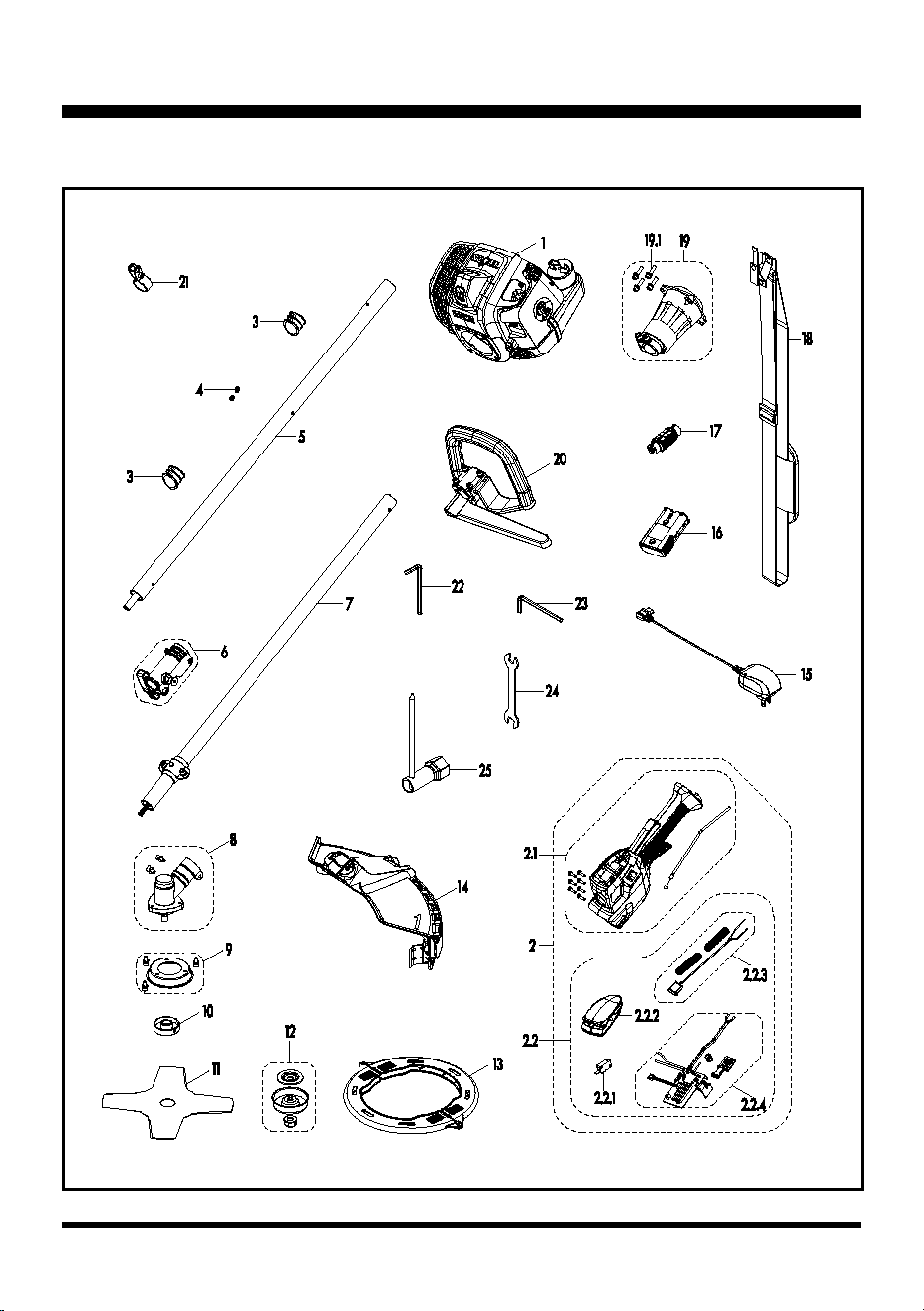
PARTS AND FEATURES
NPTBSP2609A EXPLODED VIEW

8
PARTS AND FEATURES
NPTBSP2609A PARTS LIST
Key
Number
Application Description Quantity
1 641002101 Cleva 26cc 2-Cycle Engine 1
2 321001102 Throttle-body & Start Set 1
2.1 321001103 Throttle-body Set 1
2.2 321001104 Starter Set 1
2.2.1 321001105 Micro Switch 1
2.2.2 321001106 Starter Switch Assembly 1
2.2.3 321001107 Stop Switch Set 1
2.2.4 321001108 PCB Assembly 1
3 321001109 Handle Spacer 2
5 641001104 Aluminum Upper Shaft 1
4 141004102 Cable Clamp 2
6 641001105 Shaft Connection Sleeve 1
7 641001106 Aluminum Lower Shaft 1
8 641001107 Gear Box 1
9 641001108 Blade Guard Assembly 1
10 221003105 Cover Plate 1
11 RBB2609A 9" Blade 1
12 641001111 Blade Clamp Assembly 1
13 641001112 Saw Blade Sheath 2
14 641001113 Debris Guard 1
15 321001127 Charger 1
16 321001114 7.2V Lithium-Ion Battery 1
17 321001113 Wire Lock 1
18 221003102 Shoulder Strap 1
19 641001115 Clutch Assembly 1
19.1 321005103 Screw 4
20 641001116 P-Handle 1
21 321001128 Shoulder Strap Clasp 1
22 321004122 M5 Hexagon Socket Wrench 1
23 321004121 M6 Hexagon Socket Wrench 1
24 321004123 Open End Wrench 1
25 321004124 Socket Wrench 1
9
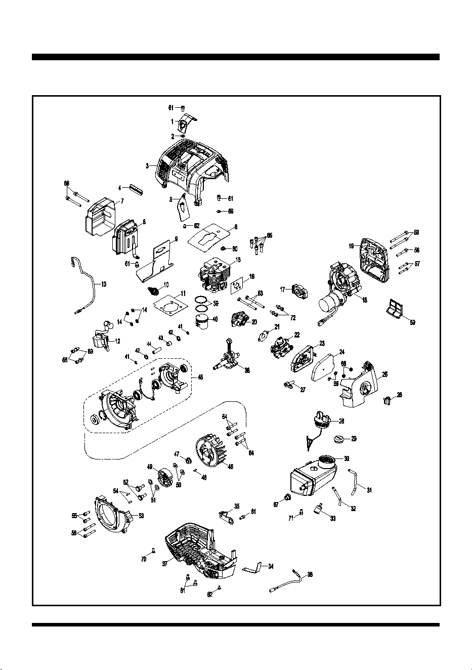
PARTS AND FEATURES
EXPLODED VIEW 26CC 2-CYCLE ENGINE

10
PARTS AND FEATURES
NPTBSP2609A PARTS LIST
Key
Number
Application Description Quantity
1 321001130 Spark Plug Cover 1
2 321001131 Nut 1
3 321001132 Upper Engine Cover 1
4 321001133 Logo 1
5 321001134 Air Deector 1
6 321002109 Cylinder Air Damper 1
7 321001136 Mufer Cover 1
8 321001137 Mufer 1
9 321001138 Insulation Sheet 1
10 321001139 Spark Plug 1
11 321002110 Gasket 1
12 641002103 Ignition Coil Assembly 1
13 321002112 Positive Stop Switch Cable 1
14 321002113 Spacer Set 4
15 321002114 Cylinder 1
16 321002115 Gasket 1
17 321001143 Pawl Assembly 1
18 321002116 Electric Starter Assembly 1
19 321002117 Rear Engine Cover 1
20 321002118 Carburetor Mount Assembly 1
21 321002119 Washer 1
22 321002120 Carburetor 1
23 321001147 Air Filter Base 1
24 321001148 Air Filter 1
25 321001149 Air Filter Cover 1
26 321001150 Rotary Knob 1
27 321001151 Choke Lever 1
28 321001152 Fuel Cap Assembly 1
29 321002121 Fuel Tank Grommet 1
30 321002122 Fuel Tank 1
31 321002123 Fuel Tube 1
32 321002124 Fuel Tube 1
33 321002125 Fuel Line Filter 1
34 321001154 Rubber Pad 1
35 321001155 Fuel Tank Bracket 1
36 321002126 Negative Stop Switch Cable 1
37 321001156 Lower Engine Cover 1

11
38 321002127 Crankshaft Set 1
39 321002128 Piston Ring 2
40 321002129 Piston 1
41 321002130 Retainer Ring 2
42 321002131 Retainer Ring 2
43 321002132 Needle bearing 1
44 321002133 Piston Pin 1
45 321002134 Crankcase Assembly 1
46 641001126 Flywheel 1
47 321002143 Flange Nut M8 1
48 311014125 Flat Key 1
49 321002145 Clutch Assembly 1
50 321002146 Washer 2
51 321002147 Corrugated Washer 2
52 321002148 Bolt 2
53 321002149 Flywheel Cover 1
54 321002150 Round Ring 2
55 321002151 Screw 2
56 321002152 Screw 3
57 321002153 Self-Tapping Screw 2
58 321002154 Screw 2
59 321002155 Lower Rear Engine Cover Plate 1
60 321002156 Heat Resistant Grommet 1
61 321001160 Screw 6
62 321001161 Self-Tapping Screw 2
63 321002157 Screw 2
64 321002158 Screw 4
65 321002159 Screw 6
66 321001163 Screw 2
67 321001164 Rubber Plug 1
68 321001165 Nut 2
69 321001166 Washer 5
70 321001162 Self-Tapping Screw 1
71 321001210 Screw 1
72 321005103 Screw 2
PARTS AND FEATURES
12
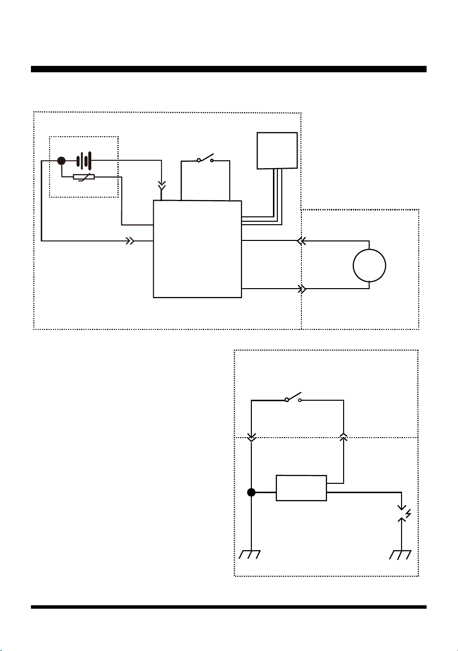
WIRING DIAGRAM AND MANAGEMENT
- IGNITION AND STARTING
2S Battery Pack
Starter Switch (Self-reset)
Stop Switch (Self-reset)
3.5 Bullet Terminal
Ignition Coil
Spark Plug
Engine
Engine Body Engine Body
3.5 Bullet Terminal
NTC
NTC
RD
RD
BK
BK BK
BK BK
BK
RD
Bullet Terminal(BL)
Bullet Terminal(BL)
Electric
Motor
EngineHandle
lgnition
Handle
M
RD
J10
J9
J8
GND M+
M-
Battery
Connector
LED
Panel
Battery Connector
PCB ASSEMBLY
VCC’
Push-Start
Ignition

13
GENERAL TROUBLESHOOTING
PROBLEM POSSIBLE CAUSE SOLUTION
The electric motor does
not start, and the battery
indicator LED ashes red.
The battery is not fully
charged or not inserted
correctly.
Charge the battery fully and insert it
correctly.
The motor does not start,
and the battery indicator
LED ashes yellow.
The battery is overheated.
Allow the battery to cool to room
temperature. Re-start the tool after about
30 minutes.
The motor does not start,
and the battery indicator
LED ashes green.
Possible short circuit in the
electric motor or the motor
drive lines.
Check if there is a short circuit in the
electric motor or the motor drive lines
referring to page 36.
The motor does not start,
and the battery indicator
LED ashes alternatively
red and green.
The starting current is
excessive - the engine or
electric motor may be seized
or cannot rotate smoothly.
Check if the engine or the electric motor is
stuck and cannot rotate smoothly referring
to page 36.
The motor does not start,
and the battery indicator
LED is continuously on.
There is an open circuit from
the PCB output to the motor
connecting line.
Check if there is an open circuit occurs
from the PCB output to the motor
connecting line referring to page 36.
The motor starts, but the
engine does not start.
The starter drive system is
broken.
Remove the electric starter. Replace the
drive system.
If drive system of the starter is in good
condition, the engine may be broken.
The engine does not start.
No spark or weak spark.
Clean or replace the spark plug. Reset the
spark plug gap 0.026”±0.002” (0.65±0.05
mm).
Check the gap between ignition coil and
ywheel. Make sure the gap is 0.012’’-
0.015’’ (0.30-0.40mm).
The air lter is blocked. Clean the air lter.
The fuel tank valve is
blocked.
Remove the blockage or replace.
Incorrect lubricant/fuel. Use correct lubricant/fuel.
The fuel tube is blocked or
broken.
Clean or replace.
Incorrect carburetor
adjustment.
Re-adjust the carburetor.
The carburetor is blocked. Remove the blockage.
Excessive oil in carburetor.
Tighten the carburetor nut or replace the
carburetor washer.

14
GENERAL TROUBLESHOOTING
The engine stops during
operation.
No fuel. Add fuel to the fuel tank.
The fuel tube is blocked. Remove the blockage.
The carburetor nut loosens
and has air leakage.
Tighten the carburetor nut or replace the
carburetor washer.
No spark or weak spark.
Clean or replace the spark plug. Reset the
spark plug gap.
Check the gap between ignition coil and
ywheel. Make sure the gap is 0.012’’-
0.015’’ (0.30-0.40mm).
Abnormal engine
compression.
Check if the piston ring sinters and the
piston and piston ring wear status. Check
the carbon deposit status in combustor.
Check the wear status inside cylinder.
Check if the spark plug loosens. Check
the gap between ignition coil and ywheel.
Make sure the gap is 0.012’’-0.015’’ (0.30-
0.40mm).
The engine is ooded.
Remove the spark plug. Clip the fuel tube
for fuel entering. Press the start button to
remove the fuel inside the cylinder.
The engine has less power.
The choke lever is closed. Open the choke lever.
The air lter is blocked. Clean the air lter.
The fuel lter is blocked. Remove the blockage or replace.
Incorrect lubricant/fuel. Use correct lubricant/fuel.
Incorrect carburetor
adjustment.
Re-adjust the carburetor.
Carburetor washer hardens. Replace.
The main nozzle of the
carburetor is blocked.
Clean or replace the carburetor if
necessary.
The spark plug is worn out. Replace with new spark plug.
The carburetor has air
leakage.
Tighten the carburetor.
The fuel has been
contaminated with water.
Empty tank and replace with clean fuel.
Mufer has carbon deposit. Remove the carbon deposit.
Exhaust port has carbon
deposit.
Remove the carbon deposit.
Piston ring sinters.
Clean the ring groove or replace the piston
ring.
Cylinder worn. Replace the cylinder.
Piston and piston ring are
worn out.
Replace.

15
GENERAL TROUBLESHOOTING
No spark.
Electrode of the spark plug
is wet.
Dry the spark plug.
Spark plug has carbon
deposit.
Remove the carbon deposit.
Spark plug insulation is
broken.
Replace the spark plug.
Spark plug gap is too big/
small.
Adjust to 0.026”±0.002” (0.65±0.05 mm).
Electrode of the spark plug
is burnt out.
Replace the spark plug.
High voltage line of the
ignition coil is broken.
Replace the high voltage line.
Stator of the ignition coil is
broken or burnt out.
Replace the stator.
Poor contact of the high
voltage line and the jump
ring.
Amend.
Spark plug cap is broken. Replace.
Engine will not start but
spark plug res.
Excess fuel inside spark
plug.
Remove the spark plug. Clip the fuel tube
for fuel entering. Press the start button to
remove the fuel inside the cylinder.
Fuel is not clean, with water. Replace the fuel.
Cylinder and piston ring
wear.
Replace.
The spark plug loosens. Tighten.
Crankcase has air leakage. Replace the gasket.
Cylinder has air leakage. Replace the gasket.
No fuel. Add fuel.
No fuel in primer bulb. Prime the bulb.
Engine is not choked. Engage the choke.
Fuel tank valve is blocked. Remove the blockage.
The engine cannot be
stopped.
The switch wire does not
connect.
Connect the wire.
The switch is broken. Replace.
The clutch engages during
idle speed.
Clutch is damaged. Replace.
The free length of the clutch
spring is too long.
Replace.
Clutch is off center. Replace.

16
GENERAL TROUBLESHOOTING
No load speed is not
stable/consistent.
Incorrect carburetor
adjustment.
Re-adjust the carburetor.
The carburetor has an air
leakage.
Replace or re-tighten.
Fuel tube is broken. Replace.
Crankcase washer has air
leakage.
Replace.
Fuel seal has air leakage. Replace.
After release the throttle
lever, the brush cutter
blade remains rotating.
Idle speed is too high. Adjust the engine.
Clutch spring is broken. Replace.
Clutch friction plate is
broken.
Replace.
The engine accelerates,
but the brush cutter blade
does not rotate.
Spline of the axle of
rotation or the spline of the
transmission yoke is worn
out.
Replace.
Irregular vibration.
Brush cutter blade is not
installed tightly.
Secure the brush cutter blade into place.
Brush cutter blade is bent. Repair or replace.
Brush cutter blade is worn
out.
Replace.
The drive shaft is bent. Replace.
Worn bearings. Replace.
Clutch is off center. Replace.
17
GENERAL TROUBLESHOOTING
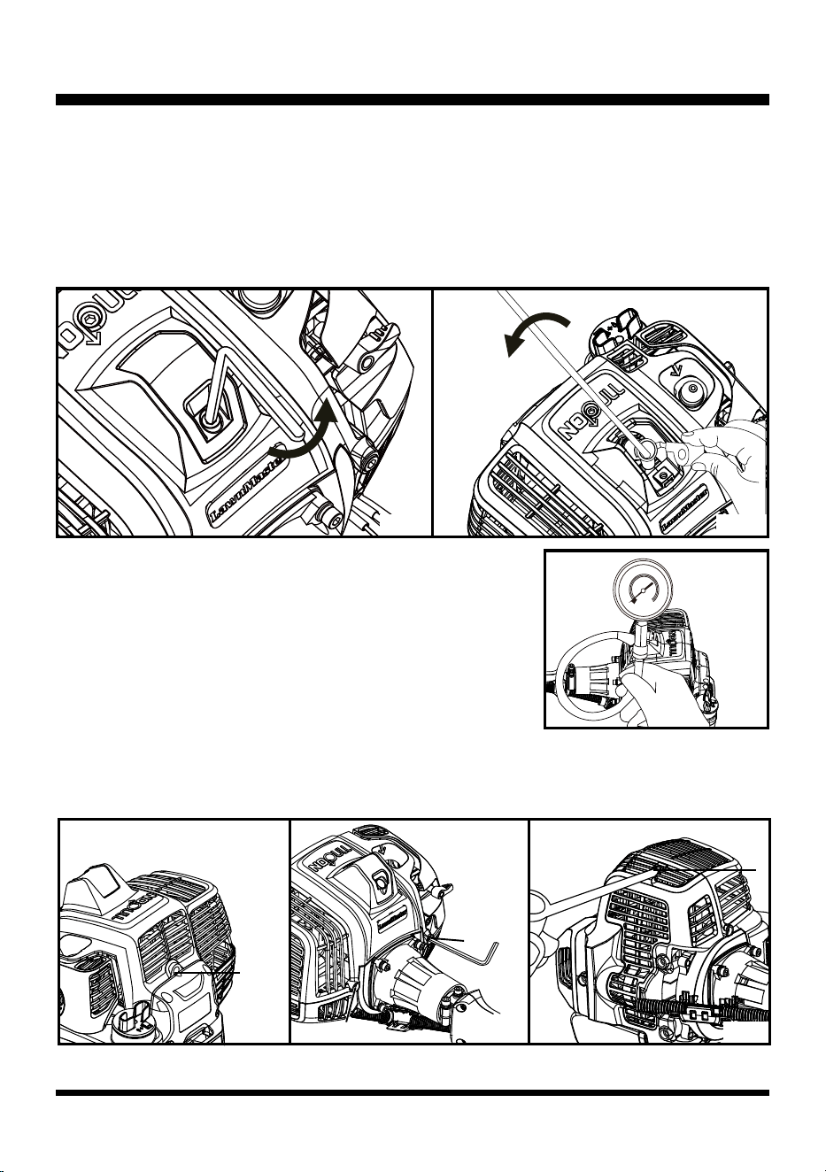
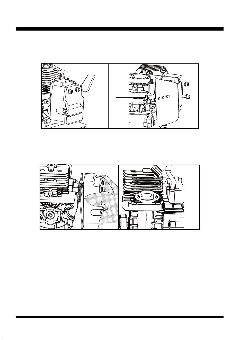
■ Rotate a compression gauge into the spark plug hole (Fig. 3).
Place the choke lever in the RUN position. Engage the throttle
safety and throttle trigger together to open the throttle and the
choke lever in the on position. Lift the start button cover and
press the start button 3-5 times until the gauge needle reaches its
peak (stops moving). Engine compression should be >0.6MPa.
Ignition System (See Figs. 4-9)
■ Remove the upper engine cover by removing the 4 screws with the provided hex wrench and
screwdriver (Fig. 4 - 6)
1
4
2
3
Fig. 5Fig. 4
Fig. 2Fig. 1
Engine Compression (See Figs. 1-3)
Low compression will cause erratic idling, low power, and hard starting when hot. To test the engine
compression:
■ Remove the spark plug cover using the provided hex wrench (Fig. 1).
■ Remove the spark plug cap. Fully cover the spark plug using the provided socket wrench. Rotate
the wrench counter-clockwise to remove the spark plug (Fig. 2).
Fig. 6
0
30
60
90
120
150
180
210
240
270
300
Fig. 3
18
GENERAL TROUBLESHOOTING
Feeler Gauge
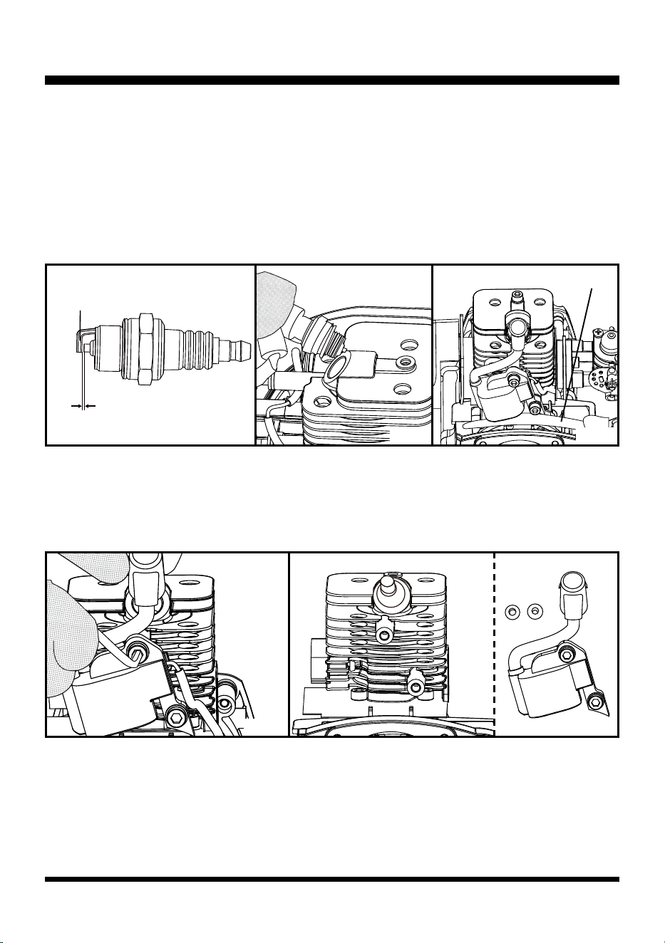
■ Remove the spark plug cover. Remove the spark plug cap and the spark plug. Check and remove
the carbon deposit in the spark plug. The spark plug gap should be 0.65±0.05mm. Inspect the
electrodes for wear and deposits (Fig. 7).
■ Install the spark plug into the spark plug cap. Contact the negative electrode to the aluminum part
(Fig. 8).
■ Press the start button to check if the spark plug sparks.
■ Check the gap between the rotor and the ignition coil. Make sure the gap is between 0.012 and 0.015
in. (0.30-0.40 mm) as instructed in step 3 of the Ignition Coil Replacement section (Fig. 9).
Fig. 8Fig. 7
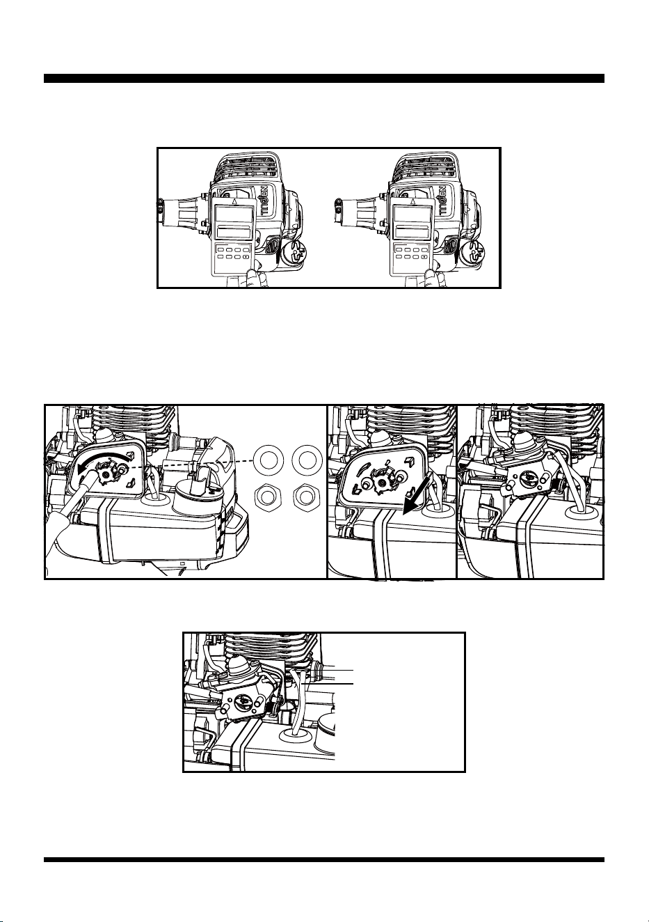
Ignition Coil Replacement (See Figs. 10-11)
■ Remove the upper engine cover.
■ Remove the spark plug cover and the spark plug cap. Remove the 2 screws. Remove the ignition
coil and the washers (Fig. 10 - 11).
Fig. 11Fig. 10
■ Replace with a new ignition coil.
■ To adjust the gap between the rotor and the ignition coil, rst insert a feeler gauge of 0.014 in.
(0.35mm) between the rotor and the ignition coil, then rotate the rotor and align the magnetic pole
of the rotor with the ignition coil. Press down the ignition coil ush against the feeler gauge. Tighten
the screws to x the ignition coil. Rotate the rotor counter-clockwise to remove the feeler gauge. Re-
check to ensure the gap is 0.012-0.015 in. (0.30-0.40 mm) (Fig. 9).
Outer Electrode
0.026 in. (0.65 mm)
Fig. 9
19
GENERAL TROUBLESHOOTING
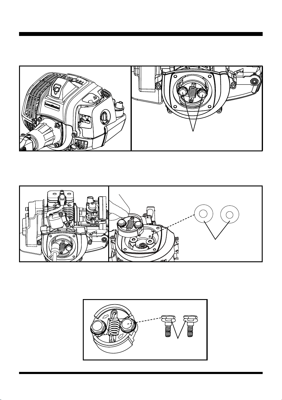
Clutch Replacement (See Figs. 12-18)
■ Remove the 4 screws to remove the transmission yoke (Fig. 12 & 13).
■ Remove the upper engine cover.
■ Unscrew the bolts on the clutch assembly using an impact driver or wrench (Fig. 14).
■ Remove the 2 bolts and corrugated washers. Then remove the clutch and at washers (Fig. 15).
■ Replace with a new clutch.
■ Slide the corrugated washers onto the bolts. Then install the bolts together with the corrugated
washers into the clutch, with the side of the clutch marked with the direction of rotation facing
upwards (Fig. 16).
Fig. 13
Fig. 15
Fig. 12
Fig. 14
Fig. 16
Bolts
Flat Washers
Corrugated Washers
20
GENERAL TROUBLESHOOTING
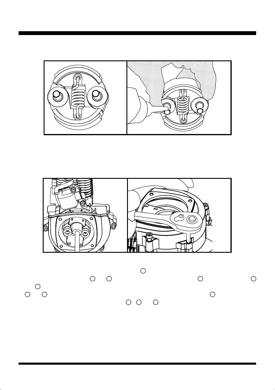
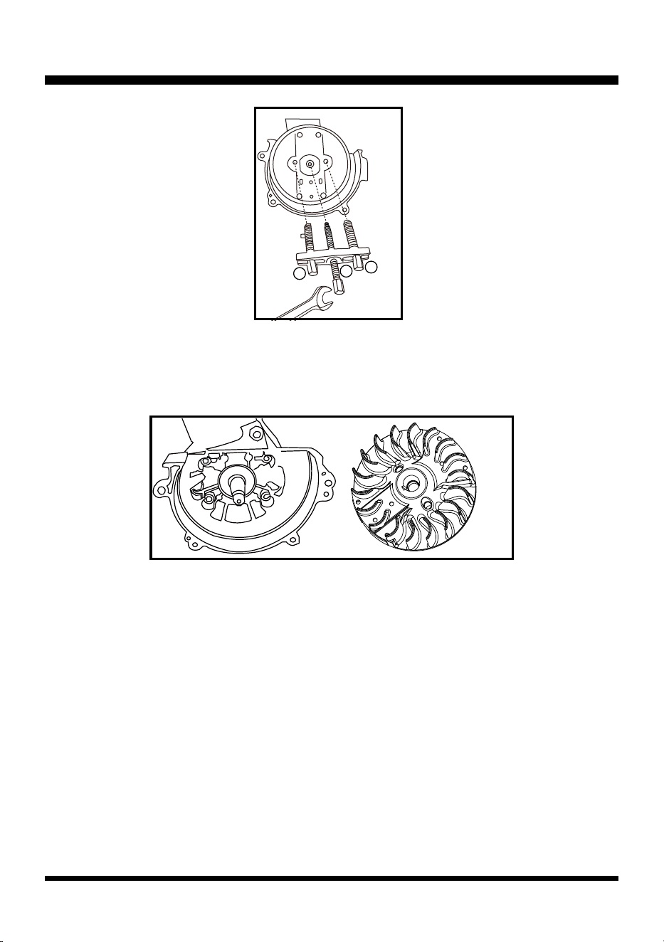
Flywheel (Rotor) Replacement (See Figs. 19-22)
■ Remove the clutch.
■ Remove the nut using an impact driver (Fig. 19).
■ Remove the 2 screws to remove the ywheel cover (Fig. 20).
■ The ywheel can be removed by a puller (Fig. 21). Choose an appropriate puller to remove the
ywheel. Before using the puller, rotate screw rod
1
counter-clockwise till it is 1/4 to 1/2 its length
through. Ensure screw rods
2
and
3
are protruded longer than screw rod
1
. Rotate screw rods
2
and
3
clockwise into the corresponding threaded holes as shown in Fig. 21. Make sure screw rods
2
and
3
are level and in same length. Then use a spanner to rotate screw rod
1
clockwise until
the ywheel is removed. Rotate screw rods
1
,
2
and
3
counter-clockwise to remove the puller
from the ywheel.
■ Turn the clutch upside down and slide the at washers onto the bolts. Apply the thread-locking glue
for 3-5 screw threads and then re-install the clutch (Fig. 17 & 18).
Fig. 18Fig. 17
Fig. 19 Fig. 20
21
GENERAL TROUBLESHOOTING
Fig. 21
Fig. 22
■ Check the woodruff key is in good condition and installed into place. Examine it for signs of damage.
Check if the rotor magnets meet the requirements. Check that the ns are in good condition.
Replace with a new ywheel if necessary (Fig. 22).
1
2
3
22
AIR & FUEL SYSTEM
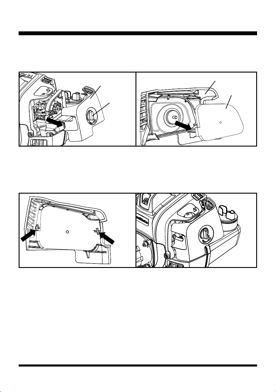
Air Filter Replacement (See Figs. 23-26)
■ Rotate the air lter knob counter-clockwise and gently pull off the air lter cover (Fig. 23).
■ Remove the air lter from the air lter cover (Fig. 24).
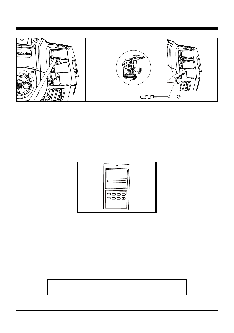
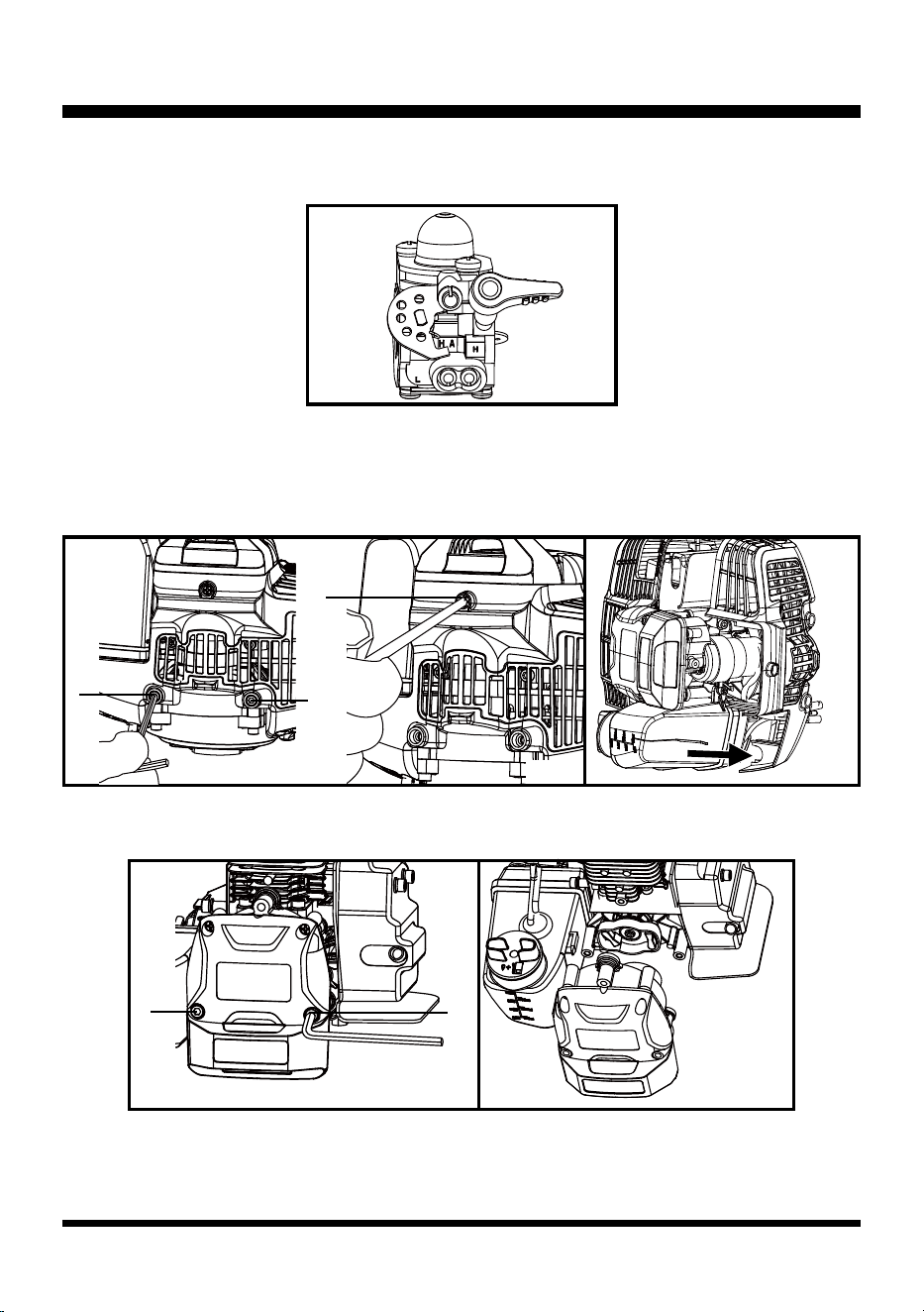
Carburetor Adjustment (See Figs. 27-33)
NOTE: The brush cutter blade will rotate during carburetor adjustment. Wear protective equipment and
observe all safety instructions.
Adjust the T screw with the Philips screwdriver (Fig. 27).
Use the carburetor adjustment tool to adjust the L screw (left) and H screw (right) (Fig. 28).
T screw: adjust the idle speed. To adjust the idle speed, adjust the T screw together with the L screw.
L screw: adjust the low speed ow rate, and assist the T screw to adjust the idle speed.
H screw: adjust the high-speed ow rate and maximum no load speed.
■ Clean the foam lter with warm soapy water and rinse. Air dry the lter.
■ Place the air lter back, ensuring that it is properly seated onto the air lter cover. Installing the lter
correctly will decrease the chances of engine wear caused by dirt entering the engine (Fig. 25).
■ Replace the air lter cover ensuring the air lter is completely covered (Fig. 26).
■ Turn the air lter knob clockwise to secure the air lter cover.
Fig. 24
Fig. 26
Fig. 23
Air Filter Cover
Air Filter Cover
Air Filter Knob
Air Filter
Fig. 25
23
AIR & FUEL SYSTEM
The requirements of carburetor ow rate:
■ With the owmeter: The idle speed ow rate is 0.26-0.28 lbs./h (0.12-0.13 kg/h). The high-speed
ow rate is 0.88-0.97 lbs./h (0.40-0.44 kg/h).
■ Without the owmeter: The idle speed is 3000+1000 rich. Adjust to maximum speed, then adjust the
H screw counter-clockwise 1/4 turn.
To adjust the carburetor, a tachometer is needed (Fig. 29). When testing the speed, the tachometer
should be placed near the spark plug of the brush cutter.
NOTE: When adjusting the carburetor, place the brush cutter on a at stable surface in an open area.
Keep the cutter off the ground and away from any objects when making adjustments. Keep all parts of
your body away from the brush cutter blade.
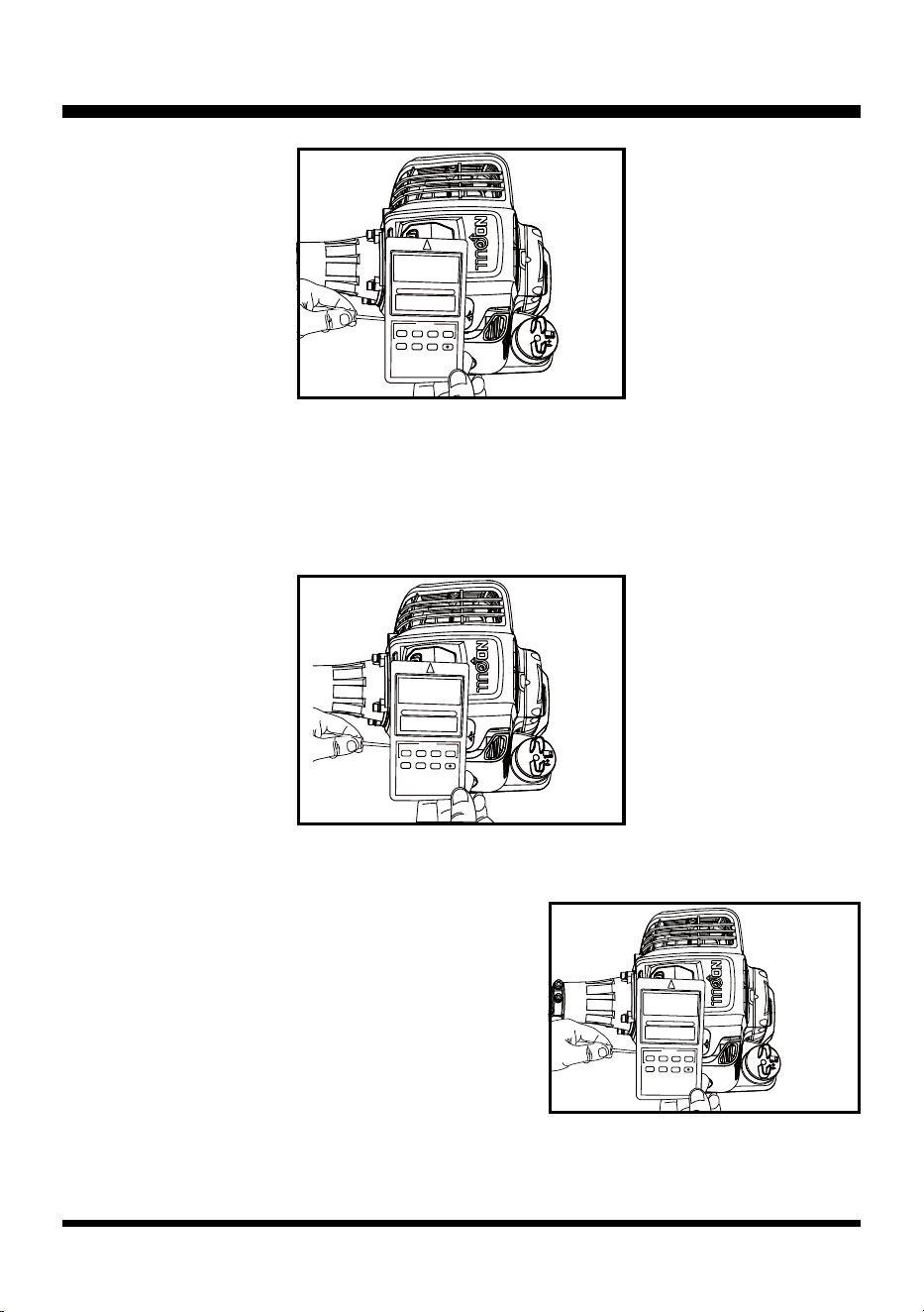
■ Start the cutter and run at half or low throttle for about 2 minutes, to warm the engine.
■ Adjust the H screw: while running the cutter at full throttle, rst turn the H screw clockwise slightly
with the carburetor adjustment tool, and observe the RPM displayed on the tachometer to verify
the correct adjustment direction (clockwise or counter-clockwise) for reaching the max no load
speed. Then turn the H screw slowly in the correct direction, and observe the RPM displayed on the
tachometer until it reaches the max speed (Fig. 30).
Fig. 28Fig. 27
T Screw
L Screw
H Screw
Fig. 29
rpm
CLOCK SET
A
B
C
D
E F G RESET
21:42
Max speed
NPTBSP2609A About 10000-10800RPM
24
AIR & FUEL SYSTEM
■ Remove the carburetor adjustment tool and re-check the max no load speed. Engage and release
the throttle trigger quickly to operate the cutter at full throttle, and observe the RPM displayed on the
tachometer. Make sure the max speed is correct.
■ Adjust the L screw: while the cutter is idling, turn the L screw clockwise using the carburetor
adjustment tool. Observe the RPM displayed on the tachometer until it reaches the max speed (Fig.
31). This max speed could be greater than or less than 4000 RPM.
Fig. 31
CLOCK SET
A
B
C
D
E F G RESET
4650
rpm
CLOCK SET
A
B
C
D
E F G RESET
10800
rpm
Fig. 30
CLOCK SET
A
B
C
D
E F G RESET
3130
rpm
Fig. 32
■ Adjust the T screw:
- If the max speed adjusted in previous step is greater than 4000 RPM, turn the T screw counter-
clockwise using the screwdriver. Observe the RPM
displayed on the tachometer until it reaches about
4000 RPM.
- If the max speed adjusted in previous step is less than
4000 RPM, turn the T screw clockwise using the
screwdriver. Observe the RPM displayed on the
tachometer until it reaches about 4000 RPM.
■ Adjust the L screw: turn the L screw counter-clockwise
using the carburetor adjustment tool. Observe the RPM
displayed on the tachometer until the idle speed reaches about 3000 RPM (Fig. 32).
25
AIR & FUEL SYSTEM
Fig. 34
■ Remove the carburetor adjustment tool and re-check the idle speed and the max no load speed
again. Make sure they are correct (Fig. 33).
General Fuel Systems Operations (See Figs. 34-50)
Carburetor Replacement
■ Remove the air lter cover and air lter.
■ Remove the 2 nuts and washers on the air lter base by rotating the socket wrench counter-
clockwise. Remove the air lter base (Fig. 34 - 36).
■ Unplug the fuel tubes with hands or pliers. PAY ATTENTION NOT to damage the tube for fuel
entering. The black tube is for fuel entering. The transparent is for fuel return (Fig. 37).
CLOCK SET
A
B
C
D
E F G RESET
10800
rpm
CLOCK SET
A
B
C
D
E F G RESET
3130
rpm
Fig. 33
Fig. 35 Fig. 36
Fig. 37
Fuel Tube (Black)
Fuel Return Tube
(Transparent)
26
AIR & FUEL SYSTEM
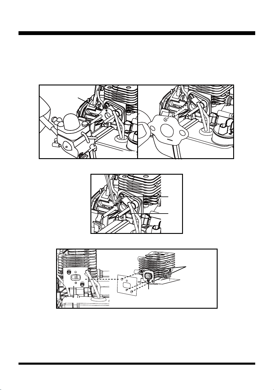
■ Remove the carburetor and the carburetor washer from the stud. Replace with a new one if
necessary. Place the washer correctly with the hole upwards. Align the hole on washer with the hole
on carburetor mount (Fig. 38 & 39).
NOTE: Make sure the new carburetor and washer should be placed in the exact order in which they
were removed.
■ If the carburetor mount needs to be replaced, remove the 2 screws to remove it (Fig. 40).
■ Remove the gasket of the carburetor mount (Fig. 41).
■ Replace with a new carburetor mount and gasket. Make sure to align the holes on the gasket with
the 2 threaded holes and the negative pressure hole on the cylinder.
NOTE: Make sure a new carburetor mount and gasket are replaced in the exact order in which they
were removed.
Fig. 38
Carburetor washer
with hole upwards
1
2
Fig. 39
Fig. 40
Threaded
Holes
Negative
Pressure Hole
Fig. 41
Gasket
27
AIR & FUEL SYSTEM
Fig. 44Fig. 43
Fig. 42
■ The choke lever is installed on the carburetor. Inspect the lever for signs of wear or damage and
replace if needed. (Fig. 42).
Fuel Tank Replacement
■ Remove the upper engine cover.
■ Remove the 3 screws to remove the lower engine cover with the provided hex wrench and
screwdriver (Fig. 43 & 44).
■ Remove the 2 screws on the electric starter assembly to remove the starter assembly (Fig. 45 &
46).
NOTE: If only replacing the fuel tank, do not remove the carburetor. Just remove the fuel tubes from
the carburetor.
1
2
3
Fig. 46
1
2
Fig. 45
28
AIR & FUEL SYSTEM
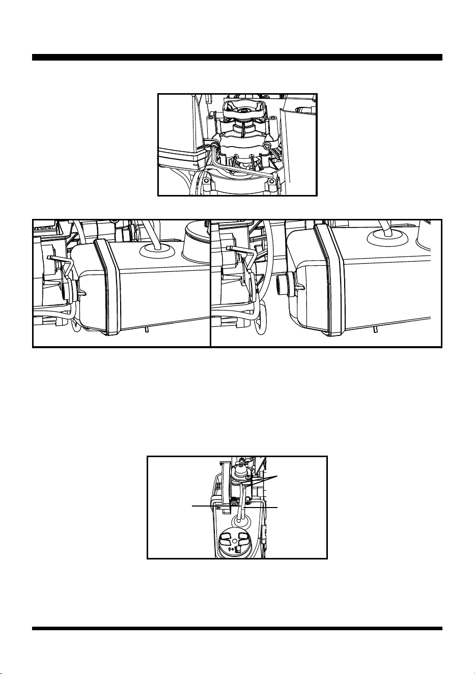
■ Remove the screw on the bottom of fuel tank (Fig. 47).
■ Unplug the rubber plug in the front of fuel tank and remove the fuel tank (Fig. 48 & 49).
■ Replace with a new fuel tank.
NOTE: Make sure all parts are replaced in the exact order in which they were removed.
Insert the Fuel Tube
Connect the fuel tubes with the carburetor. The black tube is for fuel entering. The transparent is for
fuel return. The fuel tubes should be connected to the turning position as shown (Fig. 50).
NOTE: Do not damage or fold the fuel tubes.
Fig. 47
Fig. 48 Fig. 49
Fig. 50
Fuel Return
Tube
(Transparent)
Fuel Tube
(Black)
Turning
Position
29
AIR & FUEL SYSTEM
Exhaust System Service (See Figs. 51-54)
■ Remove the upper and lower covers.
■ Remove the 3 screws to remove the mufer (Fig. 51 & 52).
■ Appropriate protective equipment is required when removing the mufer (Fig. 53).
■ The cylinder ns and housings should be checked periodically and cleaned to help prevent the
engine from overheating. Check the cylinder exhaust, piston, and piston ring for carbon build up.
NOTE: Do not allow the carbon deposit to fall into the cylinder when removing the buildup (Fig. 54).
Fig. 52Fig. 51
1
2
3
Fig. 53 Fig. 54
30
THROTTLE AND STARTER SYSTEM
Disassembly, Inspection & Repair of Throttle and Starter System (See Figs.
55-74)
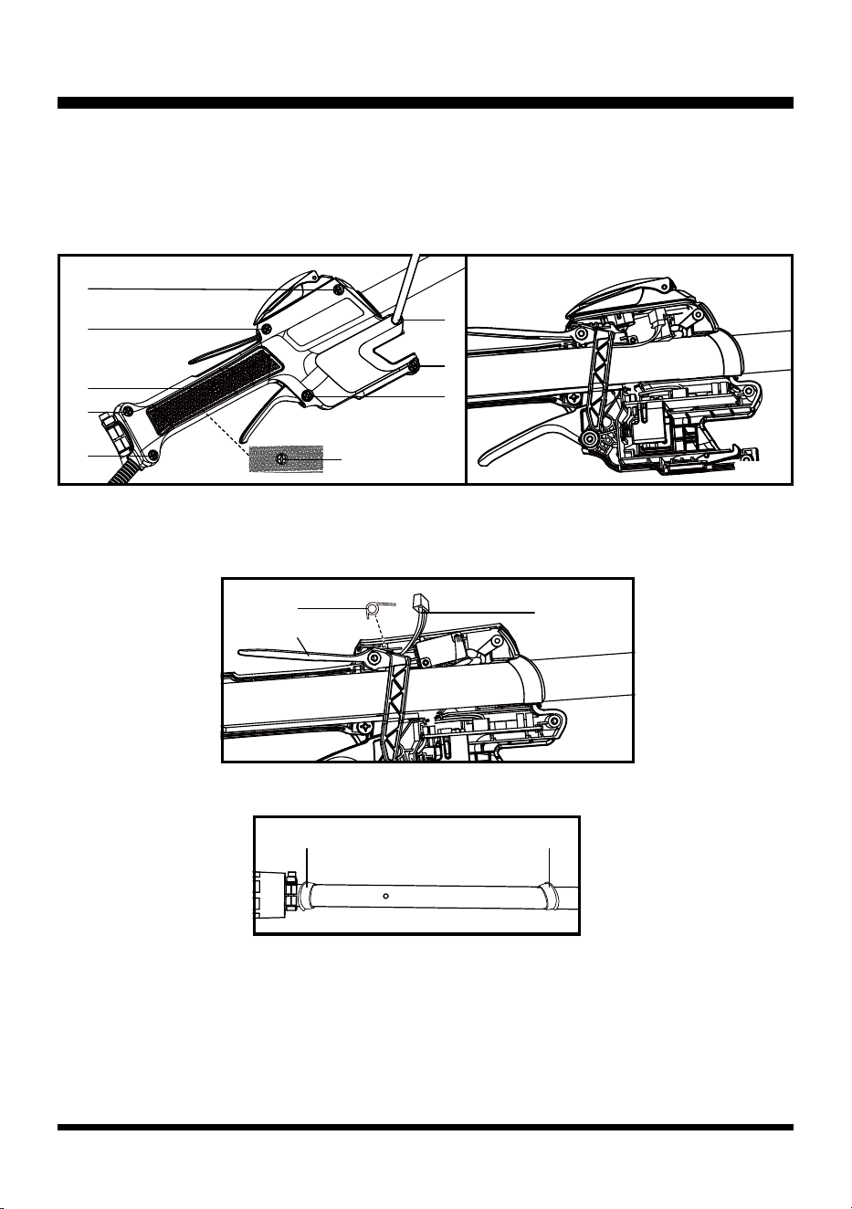
■ Remove the 9 screws on the main handle (8 screws on the right cover and 1 screw on the left
cover). Then remove the right cover of the main handle (Fig. 55 & 56).
■ Disconnect the LED light cable from the electric starter cover plate and then remove the electric
starter cover plate. Then remove the throttle safety and the torsional spring. Keep them properly for
reassembly (Fig. 57).
■ Remove the shaft. Pay attention not to change the position of the two rubbers (Fig. 58).
Fig. 56Fig. 55
1
2
3
4
5
6
9
LED Light
Cable
Torsional Spring
Throttle Safety
7
8
Fig. 57
Fig. 58
Rubber Rubber
31
THROTTLE AND STARTER SYSTEM
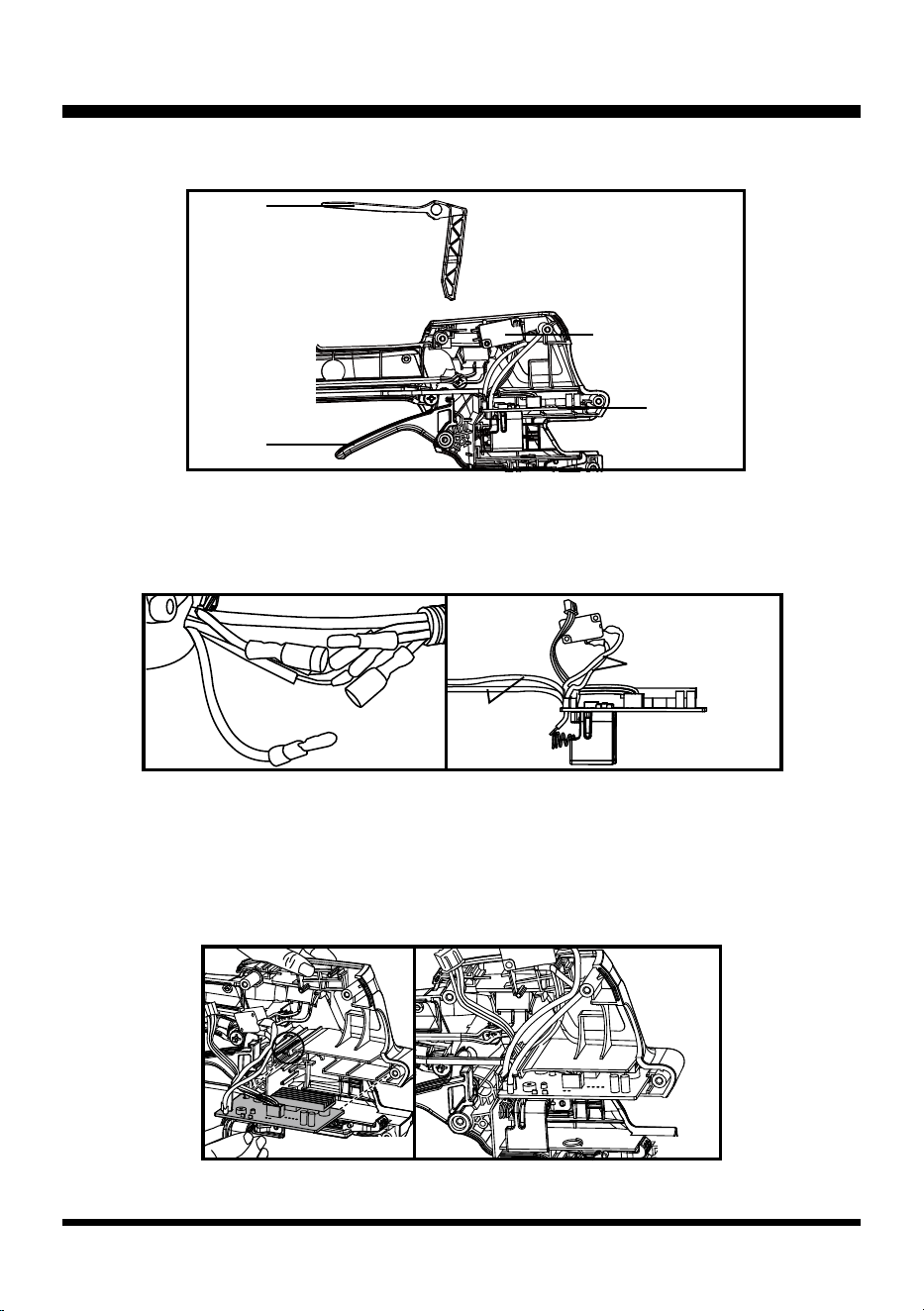
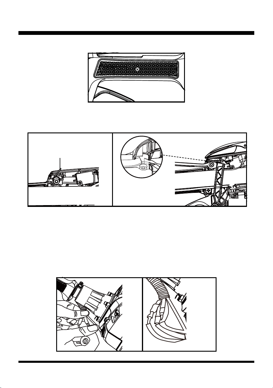
■ Check the PCB assembly, microswitch, throttle safety and throttle lever. Replace if required (Fig.
59).
■ Use a proper tool (e.g. a screwdriver) to pry off the microswitch.
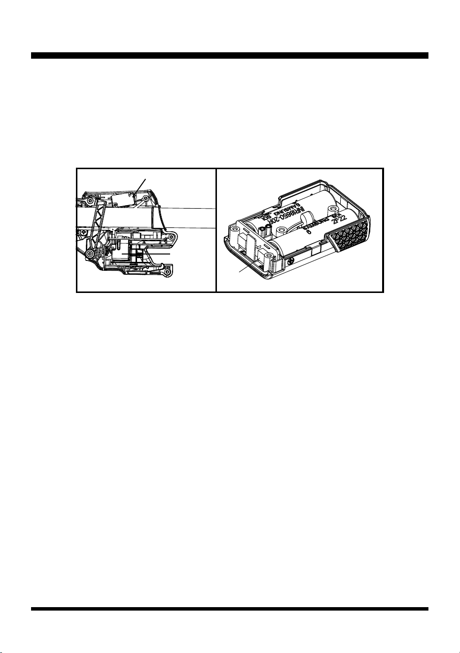
■ Open the corrugated pipe buckle and disconnect the male and female terminals of the motor drive
lines (blue). Remove the motor drive lines of the handle part from the corrugated pipe. Remove the
PCB assembly by pulling it out of its slot (Fig. 60 & 61).
■ Replace with a new PCB assembly and microswitch.
■ Pass the motor drive lines of the handle part through the corrugated pipe, and connect with the
motor drive lines of the engine part.
■ Restore the motor drive lines of the handle part, the wiring harness of the microswitch, and the LED
cable into the slot as circled in Fig. 62. Align and re-insert the PCB assembly into the slot. Make
sure it is installed into place (Fig. 62 & 63).
Throttle
Safety
Microswitch
Throttle
Lever
Fig. 59
PCB
Assembly
Microswitch Wiring
Harness
Motor Drive
Lines of
Handle
Fig. 60 Fig. 61
Fig. 62 Fig. 63
32
THROTTLE AND STARTER SYSTEM
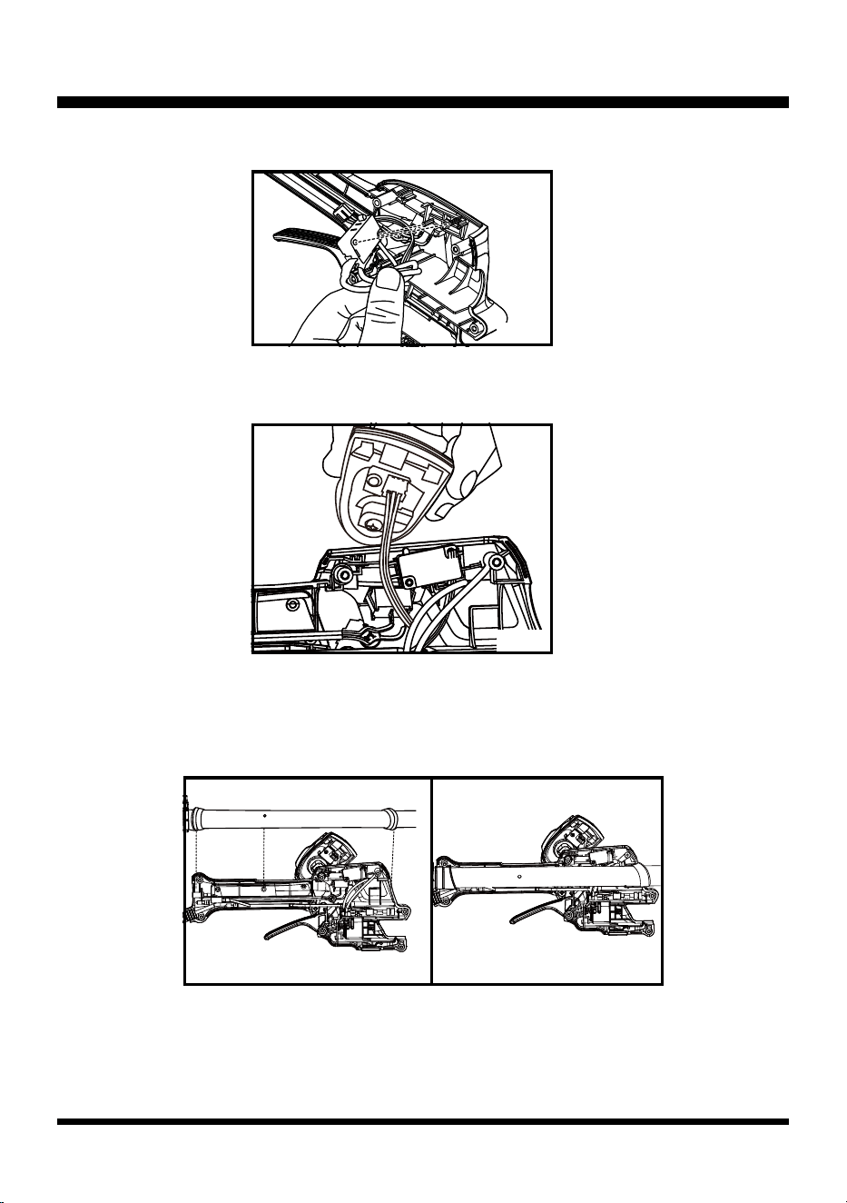
■ Restore the microswitch into place (Fig. 64).
■ Connect the LED light cable to the electric starter cover plate. Always pull gently after assembly to
ensure that terminals of the LED cable are connected in place (Fig. 65).
■ Arrange the wirings inside the handle cover to make them straight. Then align the two ends of the
handle cover with the slots of the two rubbers on the shaft, and align the hole on the handle cover
with the hole on the shaft as shown in Fig. 66. Connect the handle cover and the shaft together, and
make sure they are installed in place. (Fig. 66 & 67).
Fig. 64
Fig. 65
Fig. 66 Fig. 67
33
THROTTLE AND STARTER SYSTEM
■ Turn over the handle cover and re-install 1 screw (Fig. 68).
■ To install the torsional spring and throttle safety, rst pay attention to the correct direction of the
torsional spring with the long end upwards as shown (Fig. 69). Make sure the throttle safety and the
torsional spring are installed into place (Fig. 70). Install the electric starter cover plate.
■ Restore the right cover of the main handle by tightening the 8 screws.
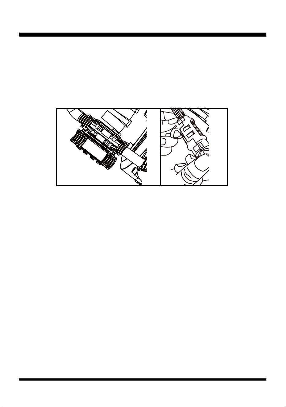
Power Line Connection
■ Align and connect the male and female terminals of the wiring harness of the main handle to the
male and female terminals of the wiring harness of the engine. Always gently pull the wiring harness
once they are connected and make sure they are connected well without any loosening. Check that
all the insulation covering outside the wiring harness wrap the terminals completely. Ensure the
metal terminals are not exposed (Fig. 71 & 72).
Fig. 68
Fig. 69 Fig. 70
Torsional Spring
Fig. 72Fig. 71
34
THROTTLE AND STARTER SYSTEM
■ Wrap the wiring harness of the engine with the opened corrugated pipe. One end of the wiring
harness is exposed and another end of the power lines should be straightened out and thrust into
the engine cover.
■ Wrap the connected terminals of the wiring harness with the corrugated pipe buckle (Fig. 73 & 74).
■ Recheck to ensure that all the insulation covering outside the wiring harness should wrap the
terminals completely and all the metal terminals are not exposed. The upper and lower covers of
the corrugated pipe buckle must be connected tightly, without any warp or twist.
Fig. 74Fig. 73
35
NOPULL
TM
STARTER SYSTEM
Special troubleshooting instructions for No-Pull™ Start Button (See Figs.
75-82)
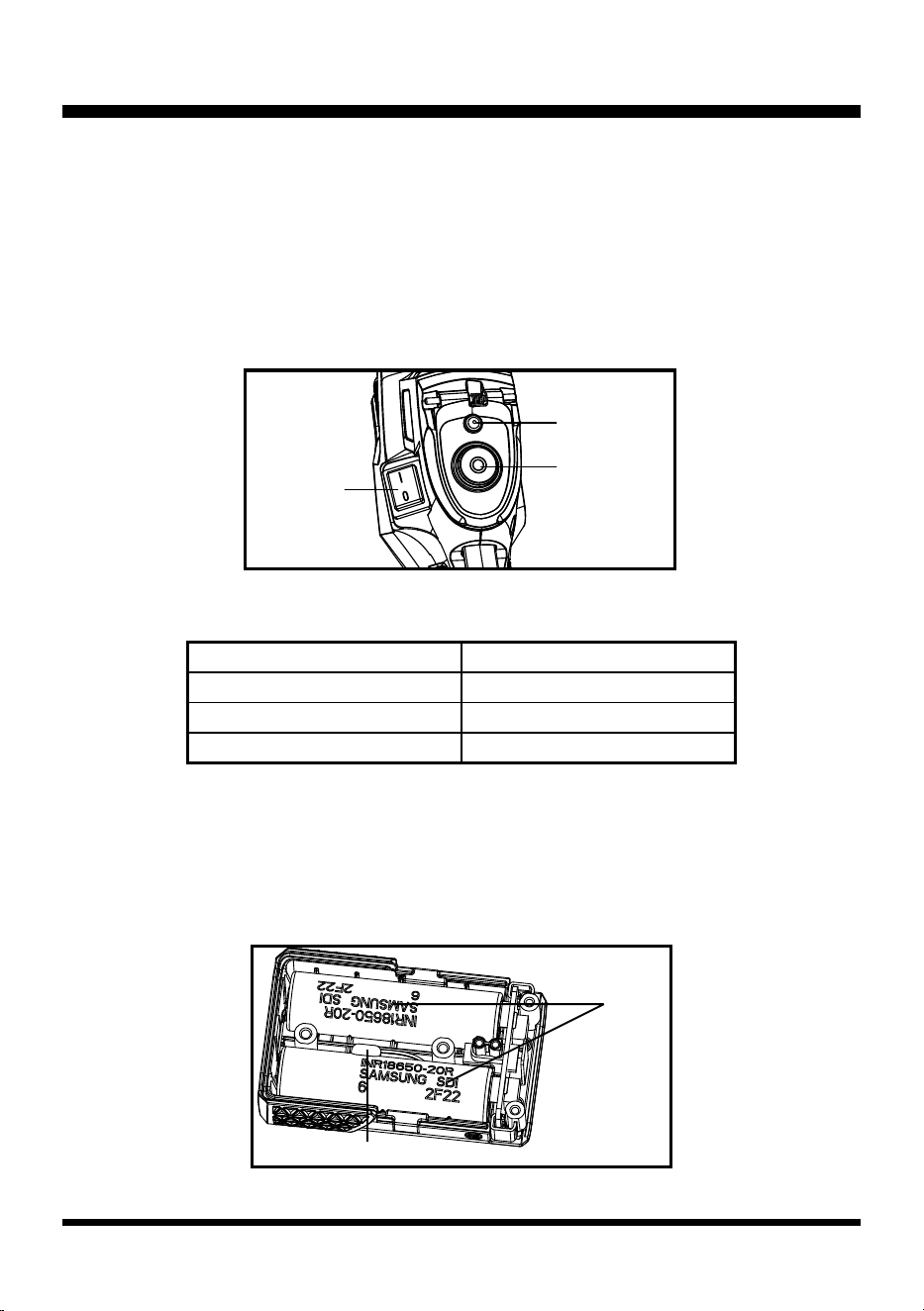
Starting Operation
Lift the start button cover and press the start button to start the electric motor. Release the start button
to stop the electric motor (Fig. 75).
NOTE: When the start button remains pressed, the electric motor will run for about 5 seconds then
it will stop automatically. When this occurs, release the start button and press it again to re-start the
electric motor.
Troubleshooting
■ The electric motor does not start when pressing the start button. According to LED indictors, the
possible causes are as below:
A. Yellow ashing of the battery indicator LED indicates battery cells are too hot and needs to cool to
room temperature (Fig. 76).
During the starting process the LED will indicate the battery voltage as below if there is no alarm
indicator:
Tolerance is ±0.2V
Battery Voltage LED Status
≥7.7V Green
7.1V-7.7V Orange
6.6V-7.1V Red
Fig. 75
LED
Start Button
Stop Switch
Fig. 76
Battery
Cells
NTC
36
NOPULL
TM
STARTER SYSTEM
B. Red ashing of the battery indicator LED indicates that battery voltage is too low and needs to be
charged.
C. Green ashing of the battery indicator LED indicates that a short circuit occurs in the electric starter.
Check the electric motor and the motor drive lines as below:
Open the corrugated pipe buckle and disconnect the male and female terminals of the motor drive
lines (blue) (Fig. 77). Press the start button and check if the LED ashes green. LED does not ash -
the short circuit occurs in the electric motor or the motor drive lines of the engine. LED ashes green -
the short circuit occurs in the motor drive lines of the handle.
D. Alternate red and green ashing of the battery indicator LED indicates that an overcurrent occurs in
the electric starter part. Check if the engine is stuck and cannot be rotated smoothly. Check if there
is any foreign matter, such as metal, magnetized on the ywheel.
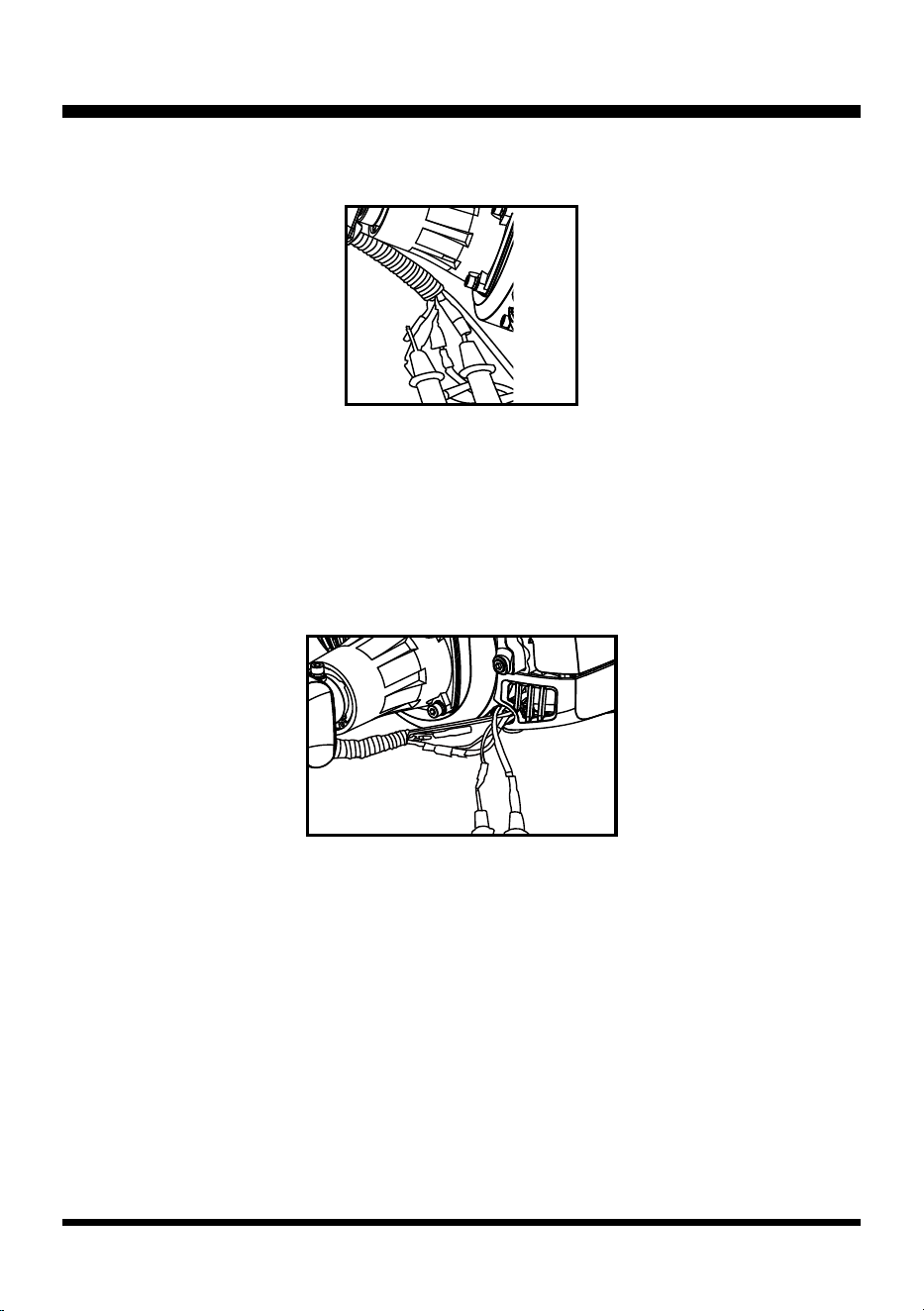
E. If the battery indicator LED is continuously on, check that if an open circuit occurs from the PCB
output to the motor connecting line.
When pressing the start button and the LED is continuously on, test the voltage output in the motor
drive lines using the DC voltage stall of multi-meter (Fig. 78).
If there is voltage output, the possible causes are as below:
1). The electric motor has broken down;
2). The motor drive lines of the engine have detached from their welding position to the electric
motor;
3). There is loose or failed contact in the connection from the motor drive lines of the engine to the
male and female terminals in the corrugated pipe buckle.
If there is no voltage output, the possible causes are as below:
1). The motor drive lines of the handle have detached from their welding position to the PCB;
2). There is loose or failed contact in the connection from the motor drive lines of the handle to the
male and female terminals in the corrugated pipe buckle.
Fig. 77
Red (+)
Black (-)
Terminals of
motor drive
lines (Blue)
Fig. 78
Test by
multi-meter
37
NOPULL
TM
STARTER SYSTEM
F. If the battery indicator LED does not turn on, the possible causes are as below:
1). The microswitch is broken. Replace it.
2). The wiring harness of the microswitch has detached. Re-weld it.
3). There is failed contact in the battery connector to the PCB. Adjust the battery connector (Fig.
79).
4). The battery does not have voltage output. Use a multi-meter to test if an open circuit occurs in
the fuse of the battery. If yes, replace it (Fig. 80).
■ The electric motor starts then stops when pressing the start button. According to LED indictors, the
possible causes are as below:
A. If there is no LED ashing, the start button may have broken (or if the start button remains pressed
for 5 seconds, the motor will stop automatically).
B. Green ashing of the battery indicator LED indicates a short circuit in the electric starter. Check the
electric motor and the motor drive lines as illustrated above.
C. Alternate red and green ashing of the battery indicator LED indicates an overcurrent in the electric
starter. Check if the engine is stuck and cannot be rotated smoothly.
■ The electric motor starts normally but the LED does not turn on when pressing the start button.
Possible causes are:
A. There is loose, or failed contact, or fall-off in the connection of PCB or LED panel to the at cable.
B. LED panel is broken.
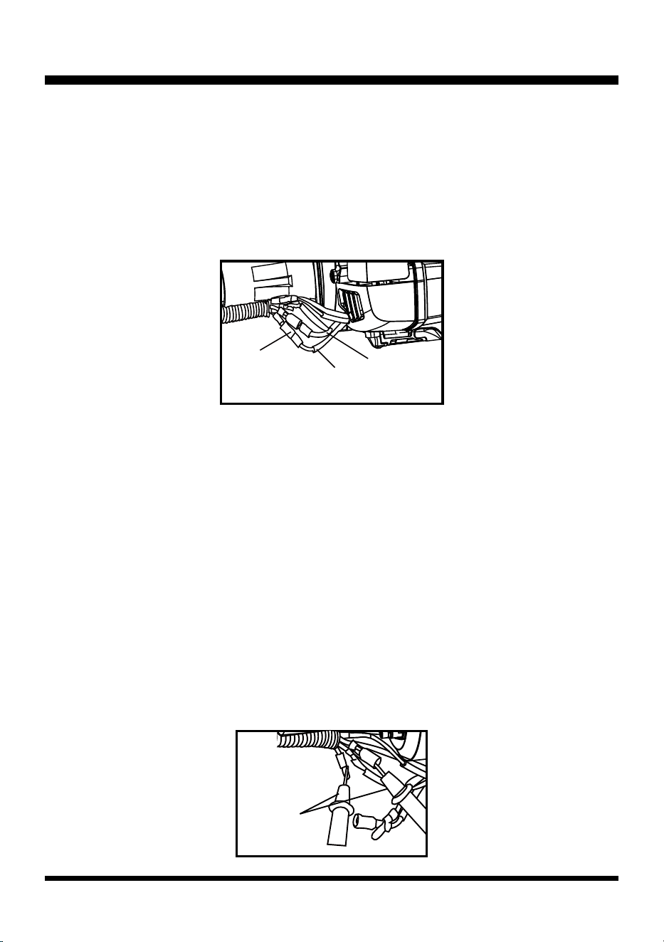
■ The engine cannot be stopped when pressing the stop switch. The possible causes may be that the
stop switch has failed or the wiring harness of the stop switch has broken. Check as below:
Open the corrugated pipe buckle, disconnect the male and female terminals of the stop switch wiring
harness (covered by two transparent insulation covering):
A. Press the stop switch, test the stop switch wiring harness of the handle part using the resistance
stall of multi-meter (Fig. 81). If conduction fails, the possible causes are:
1). The wiring harness of the handle has detached from their welding position to the stop switch;
2). There is loose or failed contact in the connection of the wiring harness of the handle part to the
Fig. 80Fig. 79
Microswitch
Battery
Connector
Fuse
38
NOPULL
TM
STARTER SYSTEM
male and female terminals in the corrugated pipe buckle;
3). The stop switch has broken.
B. Test the stop switch wiring harness of the engine (Fig. 82). If conduction fails, the possible causes
are:
1). An open circuit in the connection position between the wiring harness of the engine and the
ignition coil;
2). An open circuit in the connection position between the wiring harness of the engine part and
the engine cover;
3). There is loose or failed contact in the connection between the wiring harness of the engine and
the bullet terminals.
Fig. 82
Fig. 81

39
26CC 2-CYCLE ENGINE
Internal Engine Disassembly Inspection & Repair
Engine Start Requirements and Inspection
■ Ignition System: Require a strong spark in the best ignition time. Inspection sequence (from exit to
entrance): spark plug → spark plug cap → starter switch → high voltage line, ground line and on-off
switch line → igniter→ rotor.
■ Fuel System and Carburetor: Air and fuel mixture supplied at the optimum ratio. Inspection
sequence (from entrance to exit): fuel tank cap → fuel → fuel lter → fuel tube → carburetor →
carburetor intake.
■ Compression: Keep optimum cylinder pressure. No loss in this pressure. Inspection sequence (from
external to internal): external condition → fastening condition → cylinder → piston → crankcase.
■ Battery: Sufcient battery capacity.
■ Electric motor: Good motor performance.
Engine Disassembly and Inspection
■ Spark plug: Inspect the spark status. Remove carbon deposit. Inspect electrodes for wear and
deposits. Adjust the spark plug gap (0.65±0.05mm).
■ Air lter: Clean the air lter after every 5 hours of use. Inspect the lter for damage and replace with
a new lter if necessary.
■ Carburetor: Adjust the L/H/T screws when adjusting the carburetor.
■ Remove the upper and lower engine covers.
■ Electric starter assembly: If the electric starter malfunctions, disassemble it to check if the electric
motor is broken; test if the wires are in good condition and the gears are in working order.
■ Fuel tank: Check if there is leakage in the tank or in the fuel tube connection. Replace the fuel tank
if leakage occurs.
■ Mufer: Check and clean carbon deposit. The brush cutter should never be operated without the
mufer in place.
■ Clutch: If the engine speed is lower than 4200 RPM and the brush cutter rotates rapidly, the clutch
needs to be replaced.
■ Flywheel (rotor): If the engine overheats, check if rotor ns are in good condition. Always replace
the rotor if rotor ns are missing or if there is visible damage to the rotor. If the spark is too small,
check the magnets. Test the rotor magnets by placing a large socket on the rotor magnets. Shake
the rotor, the magnets should hold on to the socket unless the eld is weak.
■ Ignition coil: Check if the high voltage power line is in good condition. Ensure the rotor air gap is
0.012-0.015 in. (0.30-0.40 mm).
■ Crankcase: Pressure and vacuum test the crankcase.
■ Cylinder: If the above issues are checked and xed and the engine still malfunctions, examine the
cylinder exhaust, piston, and piston ring for carbon buildup. If the exhaust port is clogged, rotate the
piston until it fully covers the exhaust port, and then carefully remove the carbon with a plastic or
wooden scraper. Do not scratch the piston or damage the edges of the exhaust port.
40
GEAR HEAD AND BRUSH CUTTER BLADE
Gear Head (See Fig. 83)
After every 25 hours of use, check the level of grease inside the gear box and outside the axle. Add
approximately 0.01 lbs. (5 g) of grease if necessary.
The gear head of the straight shaft brush cutter has a left-hand rotation (Fig. 83). The screw thread
specication is M10×1.25-LH.
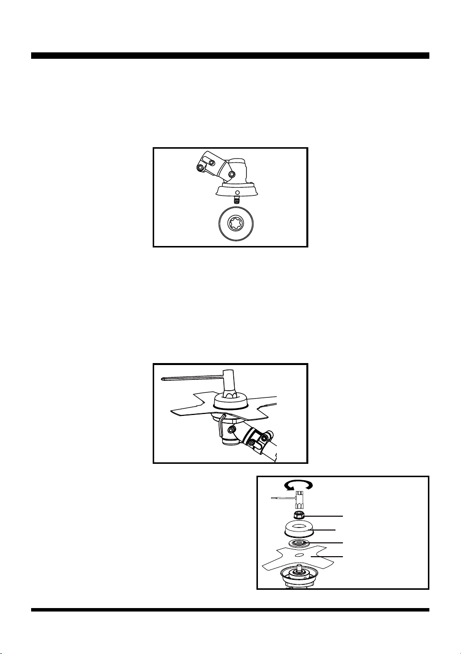
Brush Cutter Blade Replacement (See Figs. 84-85)
NOTE: The brush cutter blade is sharp. When removing the blade cover avoid contact with the blade.
Failure to do so can result in serious personal injury.
■ Stop the engine and remove the battery pack. Place the cutter on a at stable surface with the blade
facing upwards.
■ Insert the provided hex wrench into the hole on the ange to lock the spindle. Then rotate the safety
nut clockwise to remove using socket wrench (Fig. 84).
■ To install a new blade, rst remove the brush cutter
blade from the blade cover carefully.
■ Fit the blade onto the spindle with print side down.
■ Put the pressure plate onto the blade. Then put the
pressure plate cover onto the pressure plate.
■ Secure the blade with the safety nut counter-
clockwise using socket wrench (Fig. 85).
■ Remove the hex wrench.
Fig. 83
Fig. 84
Fig. 85
Safety Nut
Pressure Plate
Pressure Plate Cover
Brush Cutter Blade

41
MANUFACTURER'S WARRANTY AND CONTACT
LawnMaster
®
No-Pull
™
LIMITED WARRANTY
We take pride in producing a high quality, durable product. This LawnMaster® product carries a limited
three (3) year warranty against defects in workmanship and materials from date of purchase under
normal household use. This product carries a ninety (90) day warranty from the date of purchase when
used for commercial or rental purposes. Batteries and chargers carry a two-year warranty against
defects in workmanship and materials from date of purchase. Batteries must be charged in
accordance with the Operator's Manual directions and regulations in order to be valid. Warranty does
not apply to defects due to alterations, direct or indirect abuse, negligence, misuse, accidents, repairs,
and lack of maintenance. Please keep your receipt/packing list as proof of purchase. This warranty
gives you specic legal rights, and you may have other rights, which vary from state to state. For
product service contact your authorized dealer or call Customer Service at 866-384-8432.
Items not covered by warranty:
1. Any part that has become inoperative due to alteration, misuse, commercial use, abuse, neglect,
accident, or improper storage or maintenance.
2. The unit, if it has not been operated and/or maintained in accordance with the Operator's Manual.
3. The unit, if damage or engine failure is due to absence of 2-stroke oil, improper 2-stroke oil mix
ratio, or use of 2-stroke oils not meeting standards specied in this manual.
4. The unit, if damage is caused by the use of gasoline containing more than 10% ethanol content (E10).
5. Normal wear, except as noted below.
6. Routine maintenance items such as lubricants, blade sharpening, etc.
7. Normal deterioration of the exterior nish due to use or exposure.
8. Parts that can wear out from normal use within the warranty period, such as the blades, collection
bags, spools, spool covers, etc.
Transportation Charges: Transportation charges for the movement of any power equipment unit
or attachment are the responsibility of the purchaser. It is the purchaser’s responsibility to pay
transportation charges for any part submitted for replacement under this warranty unless such return is
requested in writing by LawnMaster
®
.
THIS WARRANTY ONLY APPLIES TO ORIGINAL PURCHASER WITH PROOF OF PURCHASE.
THIS WARRANTY IS VOID WITHOUT PROOF OF PURCHASE.