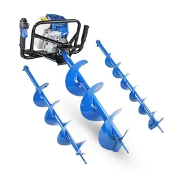
Earth Auger
Operator's Manual
MODEL EA-410
WARNING
Read rules for safe operation and instructions carefully. ECHO provides this
Operator's Manual, which must be read and understood for proper and safe opera-
tion. Failure to do so could result in serious injury.
X7504220701
X750012331
09/10
2
Copyright© 2010 By Echo, Incorporated
All Rights Reserved.
In t r o d u c t I o n
Welcome to the ECHO family. This ECHO product was designed and
manufactured to provide long life and on-the-job dependability. Read
and understand this manual . You will nd this manual easy to use, and
full of helpful operating tips and SAFETY messages.
t h e o p e r a t o r 's m a n u a l
Read and understand this manual before operation. Keep it in a safe
place for future reference. It contains specications and information
for operation, starting, stopping, maintenance, storage, and assembly
specic to this product.
ta b l e o f co n t e n t s
Introduction ................................................................2
- The Operator's Manual.......................................2
Safety ......................................................................... 3
- Manual Safety Symbols and Important
Information ........................................................3
- International Symbols ........................................3
- Personal Condition and Safety Equipment ........3
- Equipment ..........................................................6
Emission Control ....................................................... 6
Description .................................................................7
Contents ..................................................................... 9
Assembly....................................................................9
- Throttle Handle Assembly ................................. 9
- Auger Installation ............................................10
- Auger Extension Installation ...........................10
Operation .................................................................. 11
- Fuel .................................................................. 11
- Starting Cold Engine ........................................13
- Starting Warm Engine ......................................14
- Stopping Engine ...............................................14
- Drilling .............................................................15
Maintenance .............................................................16
- Skill Levels ......................................................16
- Maintenance Intervals ......................................16
- Air Filter ..........................................................17
- Fuel Filter .........................................................18
- Spark Plug ........................................................18
- Cooling System ................................................19
- Exhaust System ................................................19
- Carburetor Adjustment ..................................... 21
- High Altitude Operations ............................... 21
Troubleshooting .......................................................22
Storage ..................................................................... 23
Specications ...........................................................24
Auger Accessories .................................................... 25
Servicing Information ..............................................28
- Parts .................................................................28
- Service .............................................................28
- ECHO Consumer Product Support ..................28
- Warranty Card ..................................................28
- Additional or Replacement Manuals ...............28
Specications, descriptions, and illustrative materials
in this literature are as accurate as known at the time of
publication, but are subject to change without notice.
Illustrations may include optional equipment and acces-
sories, and may not include all standard equipment.
Ea r t h au g E r
Op E r a t O r 's Ma n u a l
3
sa f e t y
m a n u a l
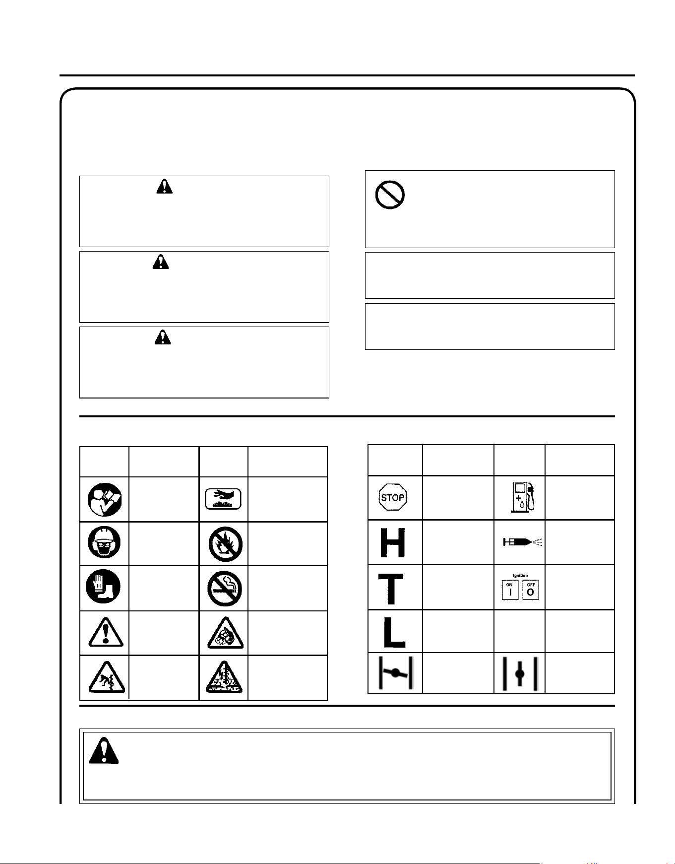
s a f e t y s y m b o l s a n d I m p o r t a n t I n f o r m a t I o n
I n t e r n a t I o n a l s y m b o l s
Hot
Surface
Carburetor Adjust-
ment
- Idle speed
Carburetor Adjust-
ment
- High Speed
Mixture
Description/
Application
Symbol
"WARNING, See
Operator's Manual
Wear Eye, Ear,
And Head Protec-
tion
Emergency Stop
Fuel And Oil
Mixture
Carburetor Adjust-
ment
- Low Speed
Mixture
Primer
Bulb
Ignition
ON/OFF
Wear Hand And
Foot Protection
Safety/Alert
DO NOT smoke
near fuel.
DO NOT allow
ames or sparks
near fuel.
Keep Feet And
Legs Away From
Auger
Maintain Firm
Grip With Both
Hands On Auger
During Operation
Never Operate
Auger In an Area
With Underground
Electric, Gas, Wa-
ter, Or Telephone
Lines
Symbol
Description/
Application
Description/
Application
Description/
Application
Symbol Symbol
Choke Control
"Cold Start"
Position
(Choke Closed)
Choke Control
"Run"
Position
(Choke Open)
p e r s o n a l c o n d I t I o n a n d s a f e t y e q u I p m e n t
Throughout this manual and on the product itself, you will nd safety alerts and helpful, informational messages pre-
ceded by symbols or key words. The following is an explanation of those symbols and key words and what they mean
to you.
WARNING
The safety alert symbol accompanied by the word
“WARNING” calls attention to an act or condi-
tion which CAN lead to serious personal injury or
death if not avoided.
CIRCLE AND sLAsh syMbOL
This symbol means the specic action
shown is prohibited. Ignoring these prohi-
bitions can result in serious or fatal injury.
CAUTION
The safety alert symbol accompanied by the word
“CAUTION” calls attention to an act or condition
which may lead to minor or moderate personal
injury if not avoided.
NOTE
This enclosed message provides tips for use, care and
maintenance of the unit.
IMPORTANT
The enclosed message provides information neces-
sary for the protection of the unit.
DANGER
The safety alert symbol accompanied by the word
“DANGER” calls attention to an act or condition
which WILL lead to serious personal injury or
death if not avoided.
WARNING
Earth Auger users risk injury to themselves and others if the auger is used improperly, or safety precautions are not
followed. Proper clothing and safety gear must be worn when operating an auger.
4
Vibration and Cold
It is believed that a condition called Raynaud’s Phenomenon, which affects the ngers of certain individuals, may be
brought about by exposure to vibration and cold. Exposure to vibration and cold may cause tingling and burning sen-
sations, followed by loss of color and numbness in the ngers. The following precautions are strongly recommended,
because the minimum exposure which might trigger the ailment is unknown.
• Keep your body warm, especially the head, neck, feet, ankles, hands,
and wrists.
• Maintain good blood circulation by performing vigorous arm exer-
cises during frequent work breaks, and also by not smoking.
• Limit the hours of operation. Try to ll each day with jobs where
operating the trimmer or other hand-held power equipment is not
required.
• If you experience discomfort, redness and swelling of the ngers fol-
lowed by whitening and loss of feeling, consult your physician before
further exposing yourself to cold and vibration.
Physical Condition
Your judgment and physical dexterity may not be good:
• if you are tired or sick,
• if you are taking medication,
• if you have taken alcohol or drugs.
Operate unit only if you are physically and mentally well.
Eye Protection
Eye protection that meets ANSI Z87.1 or CE requirements
must be worn whenever you operate the unit.
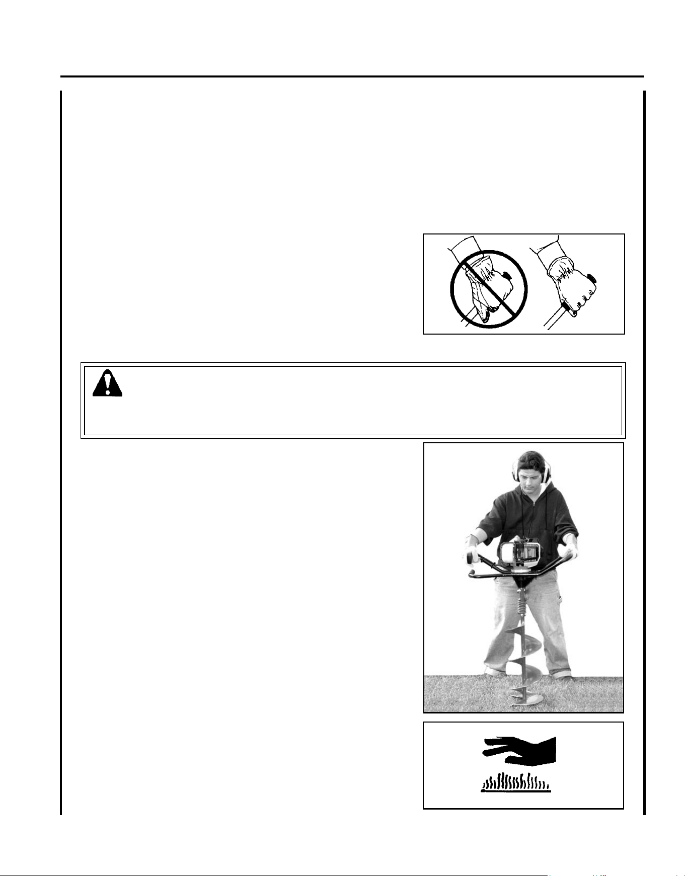
Hand Protection
Wear no-slip, heavy duty work gloves to improve your
grip on the handles. Gloves also reduce the transmission
of machine vibration to your hands.
Hearing Protection
Wear hearing protection. ECHO recommends wearing
hearing protection whenever unit is used.
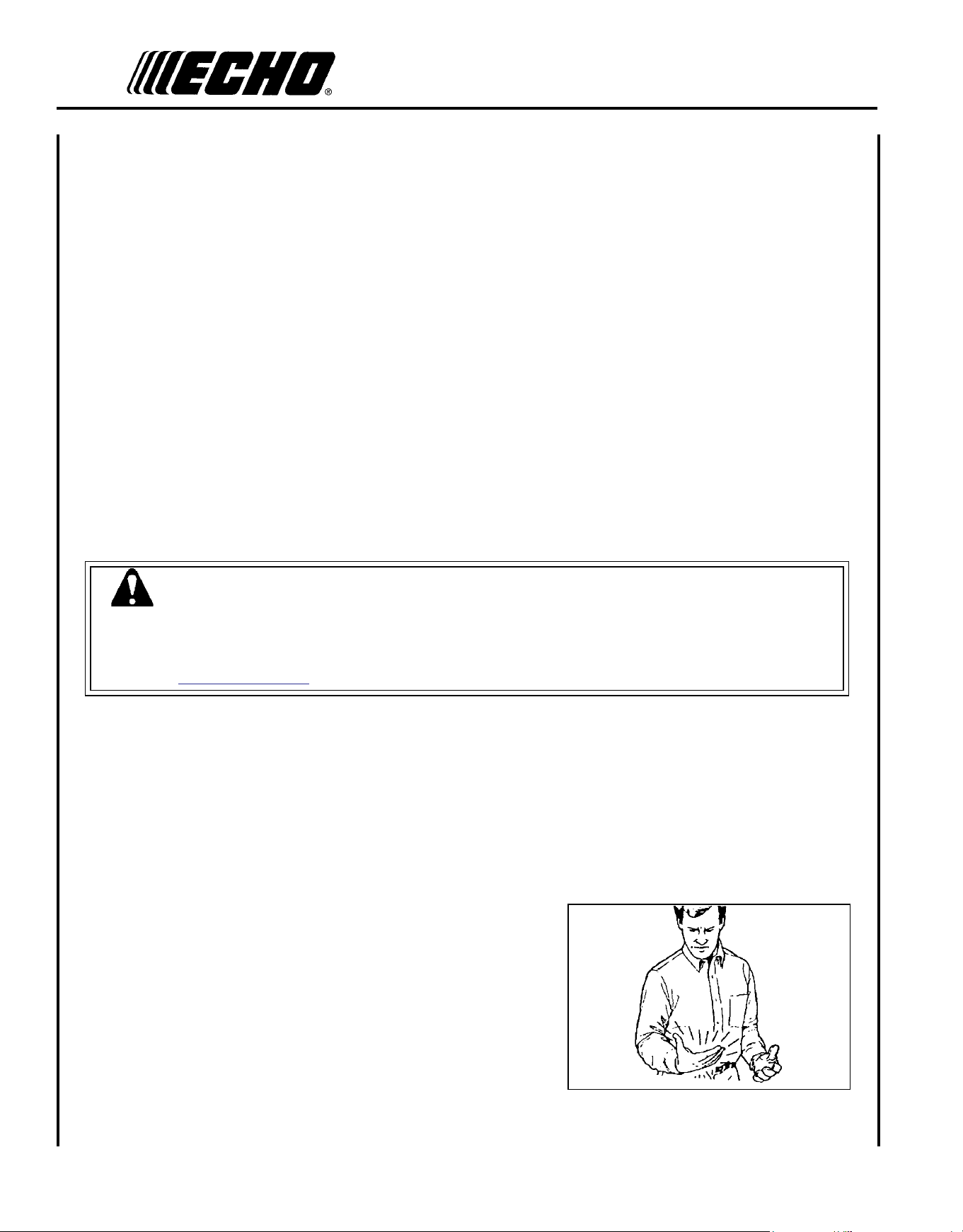
Proper Clothing
Wear snug tting, durable clothing;
• Pants should have long legs, shirts with long sleeves.
• DO NOT WEAR SHORTS,
• DO NOT WEAR TIES, SCARVES, JEWELRY, or
clothing with loose or hanging items that could be-
come entangled in moving parts.
Wear sturdy work shoes with nonskid soles;
• DO NOT WEAR OPEN TOED SHOES,
• DO NOT OPERATE UNIT BAREFOOTED.
Keep long hair away from engine and air intake. Retain
hair with cap or net.
Hot Humid Weather
Heavy protective clothing can increase operator fatigue
which may lead to heat stroke. Schedule heavy work for
early morning or late afternoon hours when temperatures
are cooler.
WARNING
The ignition components of this machine generate an electromagnetic eld during operation which may interfere
with some pacemakers. To reduce the risk of serious or fatal injury, persons with pacemakers should consult with
their physician and the pacemaker manufacturer before operating this machine. In the absence of such informa-
tion, ECHO does not recommend the use of ECHO products by anyone who has a pacemaker.
Ea r t h au g E r
Op E r a t O r 's Ma n u a l
5
Repetitive Stress Injuries
It is believed that overusing the muscles and tendons of the ngers, hands, arms, and shoulders may cause soreness,
swelling, numbness, weakness, and extreme pain in those areas. Certain repetitive hand activities may put you at a high
risk for developing a Repetitive Stress Injury (RSI). An extreme RSI condition is Carpal Tunnel Syndrome (CTS), which
could occur when your wrist swells and squeezes a vital nerve that runs through the area. Some believe that prolonged
exposure to vibration may contribute to CTS. CTS can cause severe pain for months or even years.
To reduce the risk of RSI/CTS, do the following:
• Avoid using your wrist in a bent, extended, or twisted position.
Instead try to maintain a straight wrist position. Also, when grasping,
use your whole hand, not just the thumb and index nger.
• Take periodic breaks to minimize repetition and rest your hands.
• Reduce the speed and force with which you do the repetitive move-
ment.
• Do exercises to strengthen the hand and arm muscles.
• Immediately stop using all power equipment and consult a doctor if
you feel tingling, numbness, or pain in the ngers, hands, wrists, or
arms. The sooner RSI/CTS is diagnosed, the more likely permanent
nerve and muscle damage can be prevented.
DANGER
Do not operate this product indoors or in inadequately ventilated areas. Engine exhaust contains poisonous emissions
and can cause serious injury or death.
• Provide all operators of this equipment with the operator's manual,
and instructions for safe operation.
• Review area to be augered. Beware of underground hazards such as
electrical lines, gas lines, water mains, or cable and telephone lines.
• Never use ice auger without checking with local authorities for safe
ice thickness in lakes, ponds, and rivers.
• Spectators and coworkers must be warned, and children and animals
prevented from coming nearer than 3 m (10 ft.) while auger is in use.
• Before starting the unit, equip yourself, and any person helping you,
with the required Protective Equipment and Clothing. Do not wear
loose or baggy clothing while operating the auger.
• Do not allow children to operate auger at any time.
• Always keep hands, arms, legs, and feet clear of the rotating auger.
• Do not carry the auger between holes with the engine running.
• Always shut engine off before making any repairs.
• Always hold auger handles rmly with both hands during operation.
• Maintain stable footing and balance at all times. Do not stand on
slippery, uneven, or unstable surfaces.
• Do not operate auger in any position other than upright.
• During operation, the mufer cover area will become very hot.
Avoid contact during and immediately after operation. Allow engine
and mufer to completely cool before performing any maintenance.
6
e q u I p m e n t
WARNING
Use only ECHO approved attachments. Serious injury may result from the use of a non approved attachment combi-
nation. Read and comply with all safety instructions listed in this operator manual. ECHO, INC. will not be respon-
sible for the failure of attachments or accessories which have not been tested and approved by ECHO.
• Check unit for loose/missing nuts, bolts, and screws. Tighten and/or replace as needed.
• Check that the auger is rmly attached and in safe operating condition.
• Ice blades are very sharp. Wear gloves when handling or replacing.
• Do not use any attachment, accessory, or replacement part unless it is recommended in the Operator's Manual.
• Have repairs done only by an authorized ECHO Service Dealer.
WARNING
Moving parts can amputate ngers or cause severe injuries. Keep hands, clothing and loose objects away from all
openings.
• ALWAys stop engine, disconnect spark plug, and make sure all moving parts have come to a complete stop
before removing obstructions, clearing debris, or servicing unit.
• DO NOT start or operate unit unless all guards and protective covers are properly assembled to unit.
• NEVER reach into any opening while the engine is running. Moving parts may not be visible through openings.
WARNING
Check fuel system for leaks due to fuel tank damage, especially if the unit is dropped. If damage or leaks are found,
do not use unit, otherwise serious personal injury or property damage may occur. Have unit repaired by an autho-
rized servicing dealer before using.
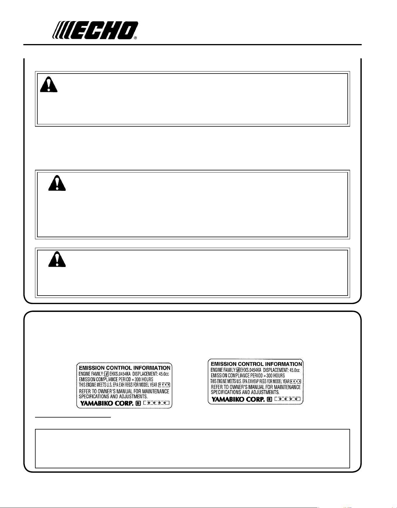
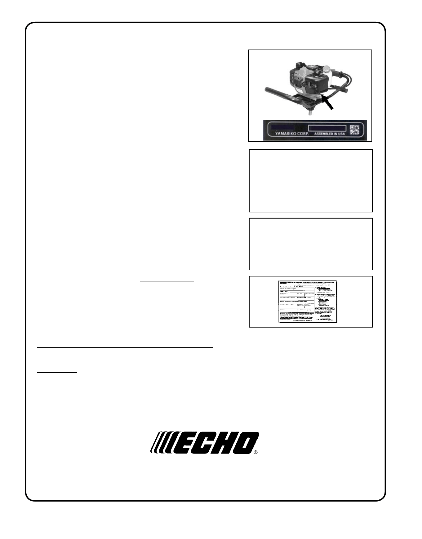
An Emission Control Label is located on the engine. (This is an EXAMPLE ONLY, information on label varies by
engine FAMILY).
PRODUCT EMIssION DURAbILITy (EMISSION COMPLIANCE PERIOD)
The 300 hour emission compliance period is the time span selected by the manufacturer certifying the engine emis-
sions output meets applicable emissions regulations, provided that approved maintenance procedures are followed as
listed in the Maintenance Section of this manual.
em I s s I o n co n t r o l (e X h a u s t & e v a p o r a t I v e )
EPA 2010 and Later
The emission control system for the engine is EM/TWC (Engine Modication and 3-way Catalyst) and for the fuel tank
the Control System is EVAP (Evaporative Emissions) or N (for nylon tank). Evaporative emission may be applicable to
California models only.
Ea r t h au g E r
Op E r a t O r 's Ma n u a l
7
5
16
2
18
12
8
9
7
11
3
2
16
15
6
13
18
3
8
12
9
7
4
3
14
17
4
11
10
19
20
1
13
11
18
14
P/N X505000920
Handle Decal
de s c r I p t I o n
Locate these safety decals on your unit. Make sure the decals are legible and that you understand the symbols, and
follow the instructions these symbols represent. If a decal cannot be read, a new one can be ordered from your ECHO
dealer. See "Servicing Information - Parts" for more information.
P/N X505002310
Hot Decal (near mufer)

8
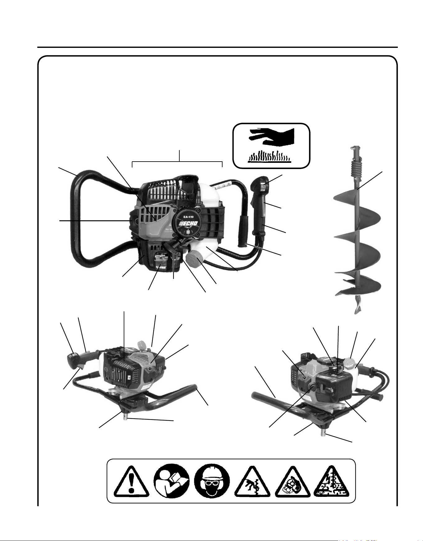
1. POWER hEAD - Includes the Engine, Clutch, Fuel System, Ignition System, Recoil Starter, and Auger Gear Case.
2. sTOP sWITCh - "SLIDE SWITCH" mounted on top of the Throttle Trigger Housing. Move switch FORWARD to
RUN, BACK to STOP.
3. LOOP hANDLE - Operator position includes Throttle Handle Assembly and loop handle. Helper position uses
loop handle.
4. PTO shaft - Power Take-Off Shaft provides power to Auger accessory.
5. AUGER AssEMbLy - Connects to PTO Shaft. Auger Assembly is purchased separately as an accessory. See page
10 for list of auger accessories.
6. sPARK ARREsTOR - CATALyTIC MUFFLER / MUFFLER -The mufer or catalytic mufer controls exhaust
noise and emission. The spark arrestor screen prevents hot, glowing particles of carbon from leaving the mufer.
Keep exhaust area clear of ammable debris.
7. FUEL TANK - Contains fuel and fuel lter.
8. RECOIL sTARTER hANDLE - Pull handle slowly until starter engages, then quickly and rmly. When engine
starts, return handle slowly. DO NOT let handle snap back or damage to unit will occur.
9. FUEL TANK CAP - Covers and seals fuel tank opening.
10. PRIMER bULb - Pumping primer bulb before starting engine draws fresh fuel from the fuel tank priming the
carburetor for starting. Pump primer bulb until fuel is visible and ows freely in the clear fuel tank return line. Pump
bulb an additional 4 or 5 times.
11. AIR CLEANER - Contains replaceable lter element.
12. ChOKE - Located above air cleaner housing. Move lever to starting position (
) (close choke) and back to run
position ( ) (open choke).
13. AIR DEFLECTOR - Deects hot engine cooling air away from operator.
14. GEAR CAsE - Sealed Gear Case provides 30.2 to 1 reduction for best combination of power and auger speed.
Requires no user maintenance.
15. ThROTTLE hANDLE AssEMbLy - Contains main operator controls- Throttle Trigger, Stop Switch, and
Throttle Trigger Lockout.
16. ThROTTLE TRIGGER LOCKOUT - Operation of the throttle trigger is prevented unless throttle trigger lockout
lever is engaged.
17. ThROTTLE TRIGGER - Spring loaded to return to idle when released. During acceleration press throttle trigger
gradually for best operating technique.
18. DECOMPREssION bUTTON - Push button to assist starting. Automatically resets after engine starts and runs.
19. LOWER hAND GRIP - Used for right-hand grip by Operator during two-man operation.
20. sPARK PLUG - Provides spark to ignite fuel mixture.
Ea r t h au g E r
Op E r a t O r 's Ma n u a l
9
co n t e n t s
The EA-410 Earth Auger Powerhead, Gear Case, and Loop Handles have been factory pre-assembled for your conve-
nience. The EA-410 Throttle Handle requires assembly. These units are designed for one-person use as an ice auger, and
one or two-person use as an earth auger.
After opening the carton, check for damage. Immediately notify your retailer or ECHO Dealer of damaged or missing
parts. Use the contents list to check for missing parts.
1 - Power Head/Handle/Gear Case Assembly
1 - Operator's Manual
1 - Warranty Registration Card
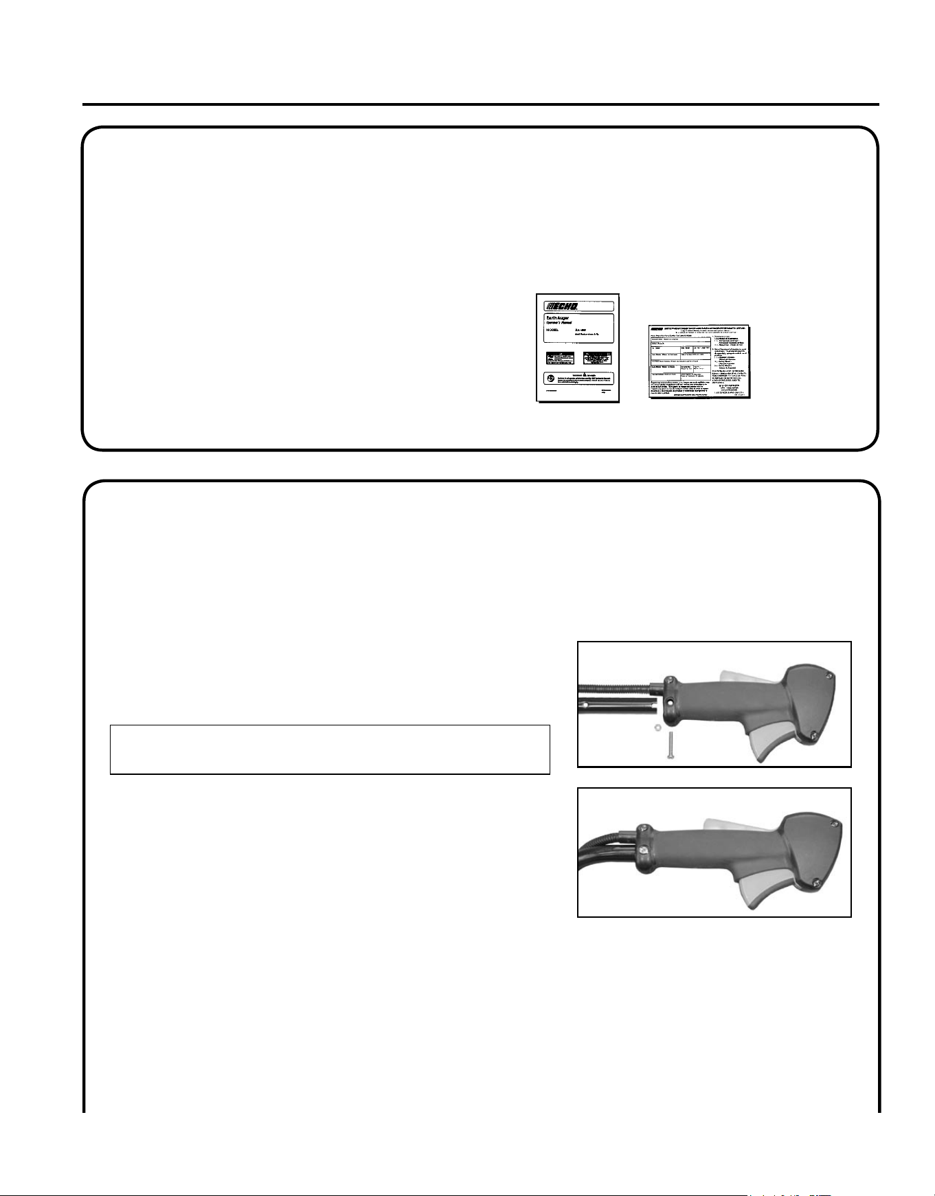
as s e m b l y
t h r o t t l e h a n d l e a s s e m b l y
Tools Required: Screwdriver, cutting tool
Parts Required: Throttle Handle Assembly, screw, hex nut
1. Cut and remove one (1) white plastic shipping tie that secures
handle assembly to packing materials.
NOTE
DO NOT cut or remove black plastic ties.
2. Remove mounting screw and hex nut from throttle handle assem-
bly, and slide throttle handle onto mounting bar.
3. Align hole in throttle handle assembly with hole in bar.
4. Secure throttle handle to bar with screw and hex nut.
5. Tighten securely.
10
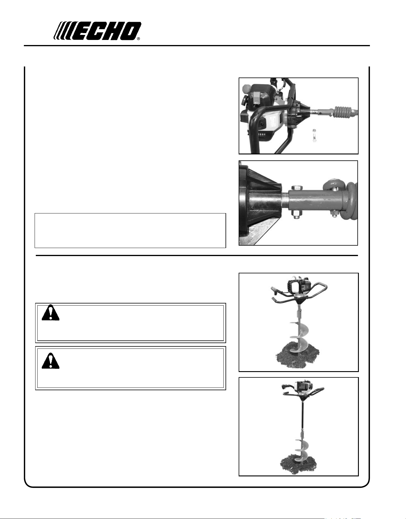
a u g e r I n s t a l l a t I o n
Tools Required: 6, 8, & 10 in. Earth Augers - (2) 9/16 in. Wrenches
2, 3, & 4 in. Earth Augers - Hex wrench.
8 & 10 in. Ice Augers - Hex wrench
Parts Required: Auger Blade Assembly - Includes: 6 - 10 in. Ear
Auger:3/8-16 x 1- 1/2" Bolt, 3/8-16 Hex Nut
2 - 4 in. Earth Augers: 3/8-16 x 1- 1/4" Socket Head
Screw
8 - 10 in. Ice Augers:3/8-16 x 1- 1/4" Socket Head
Screw
1. Carefully place engine on a at surface with mufer side down.
2. Remove assembly hardware from auger.
3. Slide auger assembly onto gear case PTO shaft.
4. Align PTO shaft mounting hole with auger mounting hole.
5. Secure auger to PTO shaft with hardware provided, and tighten
securely.
NOTE
6, 8, & 10 in. Earth Augers hardware style shown in illustration.
2, 3, & 4 in. Earth augers and 8 & 10 in. Ice Augers use socket head
screws only.
a u g e r e X t e n s I o n
Tools Required: (2) 9/16 in. Wrenches/ Hex Wrench
Parts Required: Auger Extension, 12 or 18 in. Includes assembly
hardware.
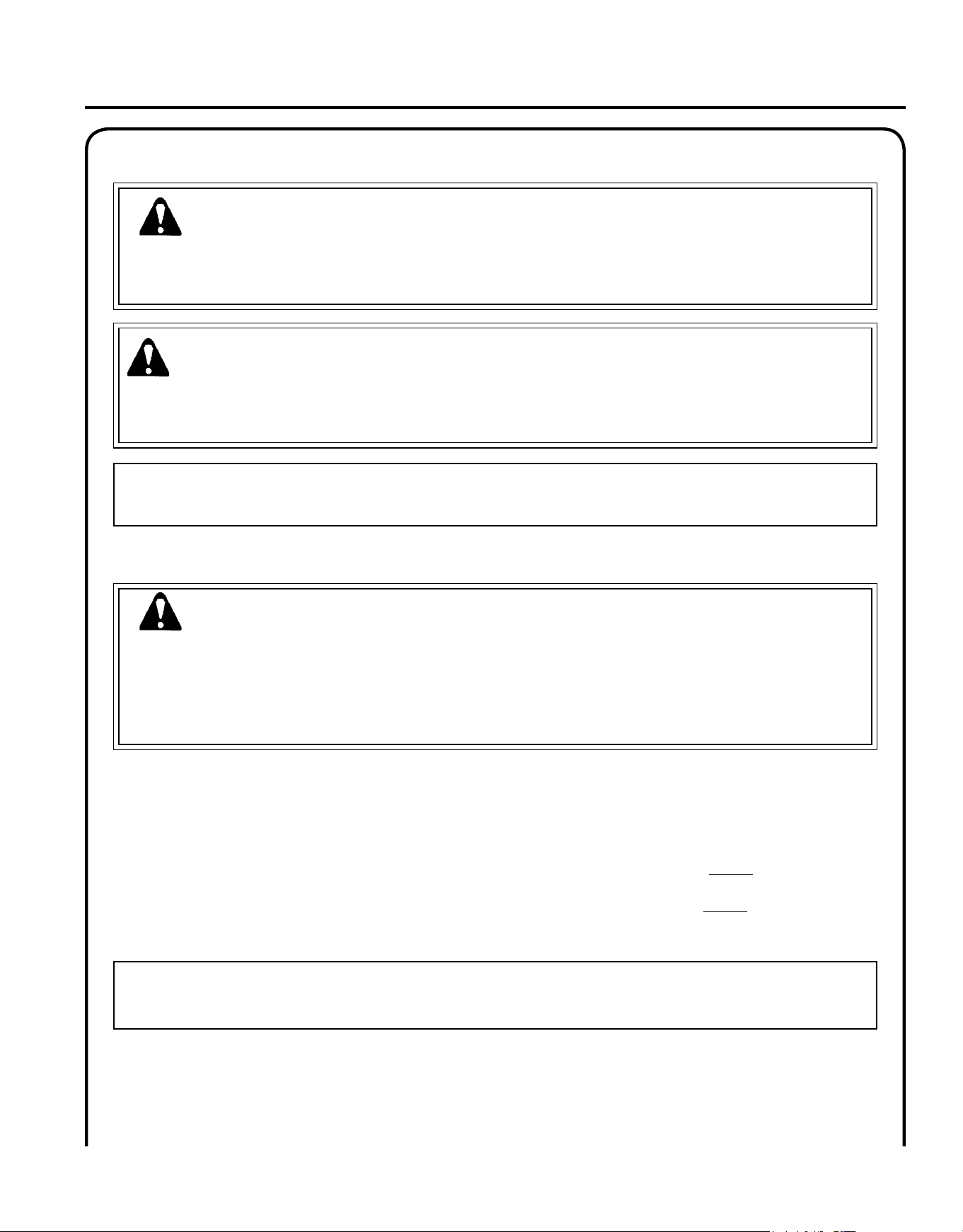
WARNING
The mufer and area around the mufer may be extremely hot.
Avoid contact with this area, otherwise serious injury may result.
WARNING
Never operate auger with handles above chest height, otherwise
you could lose control, resulting in serious personal injury.
1. Drill hole into ground 15 to 20 in. deep. Stop engine, and clean off
auger mounting bolt hardware.
2. Remove auger mounting hardware. Lift engine off auger, and
set aside. The engine should be supported on the ground by the
handles and PTO shaft.
3. Remove extension hardware.
4. Slide extension onto auger shaft, align holes, and install mounting
hardware. Tighten securely.
5. Install engine on extension shaft, and secure with hardware re-
moved in step 2. Tighten securely.
Ea r t h au g E r
Op E r a t O r 's Ma n u a l
11
NOTICE: Use of unmixed, improperly mixed, or fuel older than 90 days, (stale fuel), may cause hard starting, poor
performance, or severe engine damage and void the product warranty. Read and follow instructions in the Storage
section of this manual.
f u e l
WARNING
Alternative fuels, such as E-15 (15% ethanol), E-85 (85% ethanol) or any fuels not meeting ECHO requirements are
NOT approved for use in ECHO 2-stroke gasoline engines. Use of alternative fuels may cause performance prob-
lems, loss of power, overheating, fuel vapor lock, and unintended machine operation, including, but not limited to,
improper clutch engagement. Alternative fuels may also cause premature deterioration of fuel lines, gaskets, carbu-
retors and other engine components.
WARNING
Moving parts can amputate ngers or cause severe injuries. Keep hands, clothing and loose objects away from all
openings. Always stop engine, disconnect spark plug, and make sure all moving parts have come to a complete
stop before removing obstructions, clearing debris, or servicing unit.
op e r a t I o n
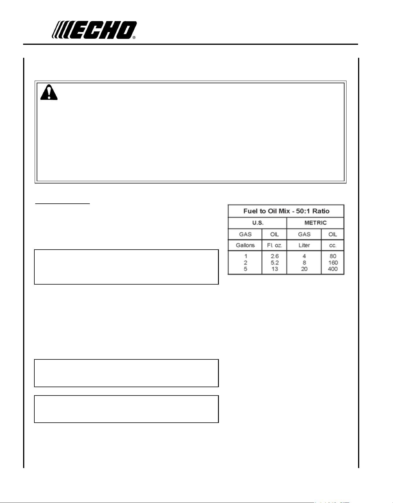
IMPORTANT
Echo premium Power Blend X
TM
Universal 2-Stroke Oil may be mixed at 50:1 ratio for application in all Echo en-
gines sold in the past regardless of ratio specied in those manuals.
Fuel Requirements
Gasoline - Use 89 Octane [R+M/2] (mid grade or higher) gasoline known to be good quality. Gasoline may contain up to
10% Ethanol (grain alcohol) or 15% MTBE (methyl tertiary-butyl ether). Gasoline containing methanol (wood alcohol)
is NOT approved.
Two stroke Oil - A two-stroke engine oil meeting ISO-L-EGD (ISO/CD 13738) and J.A.S.O. FC/FD Standards must
be used. Echo brand premium Power Blend X
TM
Universal 2-Stroke Oil meets these standards. Engine problems due to
inadequate lubrication caused by failure to use an ISO-L-EGD (ISO/CD 13738) and J.A.S.O. FC/FD certied oil, such as
Echo premium Power Blend X
TM
, will void the two-stroke engine warranty.
WARNING
Operation of this equipment may create sparks that can start res around dry vegetation. This unit is equipped with
a spark arrestor and a spark arrestor may be required. The operator should contact local re agencies for laws or
regulations relating to re prevention requirements.
12
Mixing Instructions
1. Fill an approved fuel container with half of the required amount of
gasoline.
2. Add the proper amount of 2-stroke oil to gasoline.
3. Close container and shake to mix oil with gasoline.
4. Add remaining gasoline, close fuel container, and remix.
IMPORTANT
Spilled fuel is a leading cause of hydrocarbon emissions. Some
states may require the use of automatic fuel shut-off containers to
reduce fuel spillage.
After use
• DO NOT store a unit with fuel in its tank. Leaks can occur. Return
unused fuel to an approved fuel storage container.
storage - Fuel storage laws vary by locality. Contact your local gov-
ernment for the laws affecting your area. As a precaution, store fuel in
an approved, airtight container. Store in a well-ventilated, unoccupied
building, away from sparks and ames.
IMPORTANT
Stored fuel ages. Do not mix more fuel than you expect to use in
thirty (30) days, ninety (90) days when a fuel stabilizer is added.
IMPORTANT
Stored two-stroke fuel may separate. ALWAYS shake fuel con-
tainer thoroughly before each use.
Handling Fuel
DANGER
Fuel is VERY ammable. Use extreme care when mixing, storing or handling or serious personal injury may result.
• Use an approved fuel container.
• DO NOT smoke near fuel.
• DO NOT allow ames or sparks near fuel.
• Fuel tanks/cans may be under pressure. Always loosen fuel caps slowly allowing pressure to equalize.
• NEVER refuel a unit when the engine is HOT or RUNNING!
• DO NOT ll fuel tanks indoors. ALWAYS ll fuel tanks outdoors over bare ground.
• DO NOT overll fuel tank. Wipe up spills immediately.
• Securely tighten fuel tank cap and close fuel container after refueling.
• Inspect for fuel leakage. If fuel leakage is found, do not start or operate unit until leakage is repaired.
• Move at least 3m (10 ft.) from refueling location before starting the engine.
Ea r t h au g E r
Op E r a t O r 's Ma n u a l
13
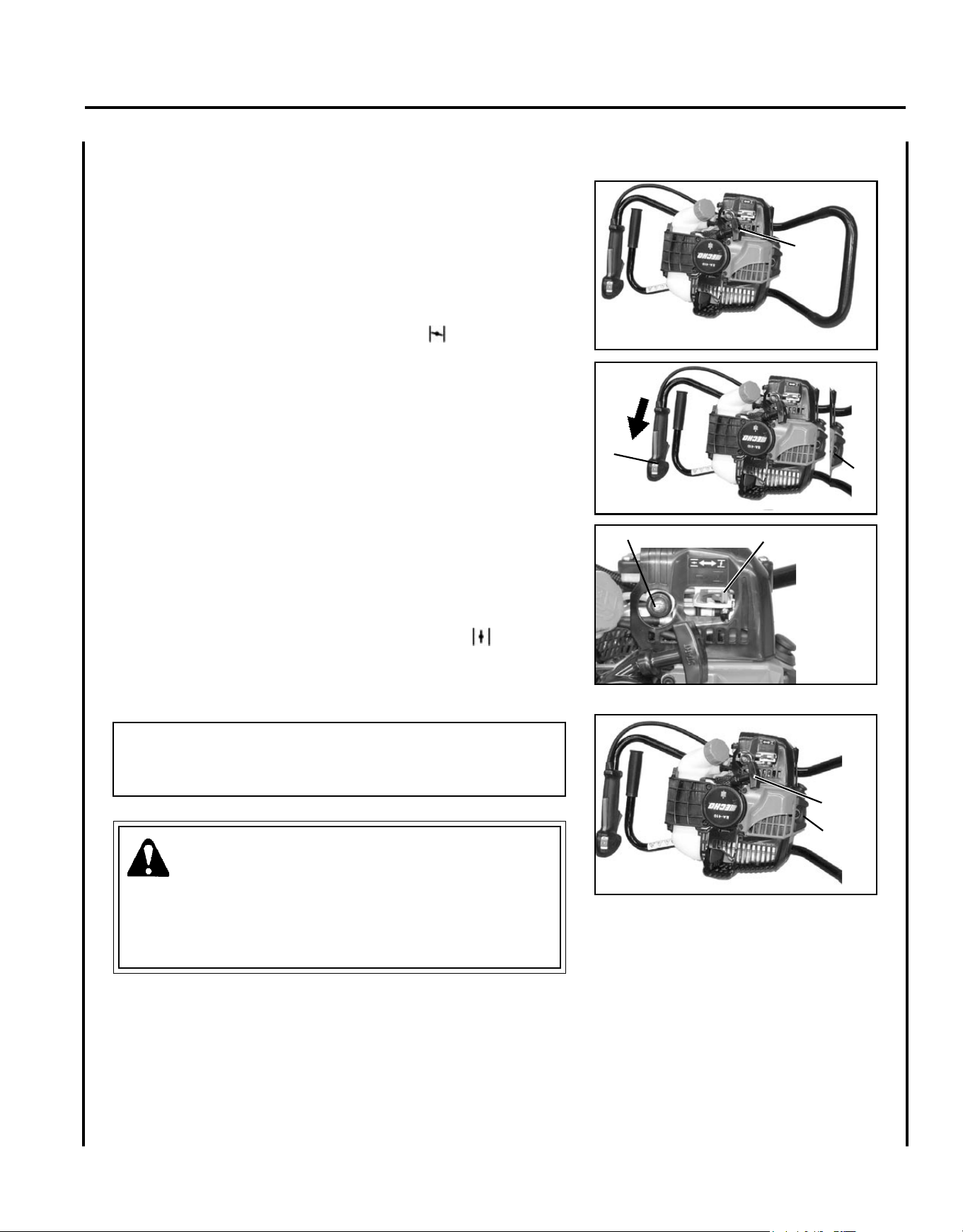
s t a r t I n g c o l d e n g I n e
1. Place auger on at surface, recoil starter handle (A) up.
2. Stop Switch.
Move stop switch button (B) forward, away from the STOP
position.
3. Choke Lever
Move choke lever (C) to Cold Start Position ( ).
4. Decompression Button
Press decompression button (D) once.
5. Primer
Pump primer bulb (E) until fuel is visible and ows freely in the
clear fuel tank return line. Pump bulb an additional 4 or 5 times.
6. Recoil Starter
Hold loop handle securely with one hand, and pull the recoil
starter handle (A) until engine res (5 or 6 pulls). Do not hold en-
gine by the throttle grip handle. DO NOT depress throttle trigger
when starting.
7. Choke Lever
Move the choke lever to the OPEN - RUN position ( ). Restart
engine if necessary and allow to warm up at idle for several min-
utes.
NOTE
After engine starts, engine decompression button will automatically
reset for normal operation.
WARNING
The auger attachment should not rotate at idle. If attachment
rotates, readjust carburetor according to "Carburetor Adjustment"
instructions in this manual or see your ECHO Dealer, otherwise
serious personal injury may result.
B
A
C
A
D
D
E
14
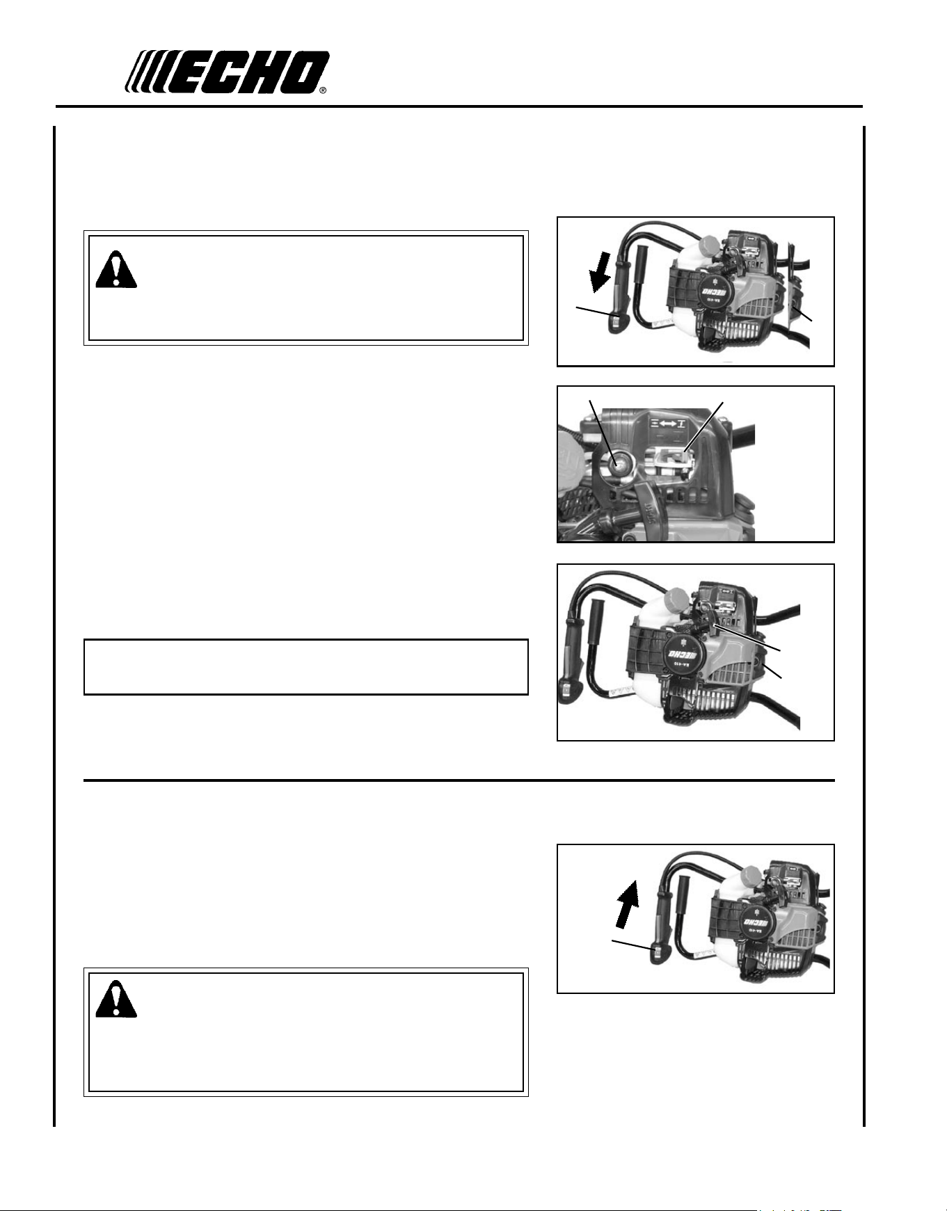
s t o p p I n g e n g I n e
1. Release Throttle.
Allow engine to return to idle before shutting off engine.
2. Stop Switch
Move stop switch button (B) backward to "STOP" position.
WARNING
If engine does not stop when stop switch is moved to STOP posi-
tion, close choke - COLD START position - to stall engine. Have
your ECHO dealer repair stop switch before using unit again.
s t a r t I n g w a r m e n g I n e
The starting procedure is the same as Cold Start, except DO NOT close
the choke.
WARNING
When engine starts, the auger attachment may rotate, even with the
throttle trigger in idle (released) position.
1. Stop Switch
Move stop switch button (B) forward, away from the "STOP"
position.
2. Primer
Pump primer bulb (E) until fuel is visible in the "Clear" fuel return
line. Pump bulb an additional 4 or 5 times.
3. Decompression Button
Press decompression button (D) once.
4. Recoil Starter.
Lay the unit on a at, clear area, and pull the recoil starter handle
(A) until the engine res.
NOTE
If engine does not start after 5 pulls, use Cold Start Procedure.
B
C
E
B
D
A
D
Ea r t h au g E r
Op E r a t O r 's Ma n u a l
15
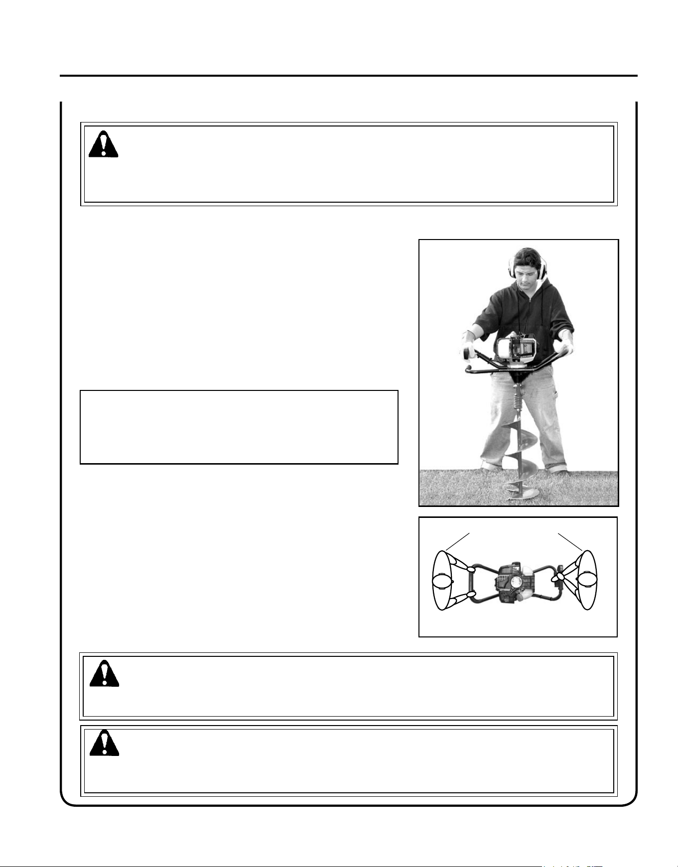
1. After starting engine, position auger upright at desired drilling
point.
2. Position feet for a stable stance, away from auger blades.
3. Firmly grip Throttle Handle Assembly and loop bar handle with
right and left hands.
4. Slowly squeeze throttle trigger to engage clutch and rotate auger.
Apply light downward pressure on handles to drill hole. Periodi-
cally, raise the auger to help clear drilling debris from the hole.
5. Overloading the auger during drilling may cause it to stop turn-
ing. When this occurs, lift the auger to reduce the drilling load on
the engine, and allow drilling debris to be augered out of the hole.
Resume drilling.
IMPORTANT
While drilling, the auger may twist suddenly and forcefully if
it contacts large rocks, roots, or other hidden obstacles. Release
throttle trigger immediately, and lift auger out of hole. Clear the
obstacles to prevent damage, and then resume drilling.
6. Drilling holes six inches in diameter or larger may be easier if two
people hold the handles on opposite sides.
7. Two-man Operation - The operator (A), guides the auger while
gripping the Throttle Handle Assembly and lower hand grip. The
helper (B), assists by guiding auger while gripping loop handle on
opposite side of auger.
8. Do not place excessive body weight on the unit. Allow auger to
drill with a shaving action using light downward pressure.
9. Do not use an ice auger in earth, or an earth auger in ice. A differ-
ent style of auger is required for each type of drilling.
10. Do not operate unit in excessively rocky ground.
WARNING
Never operate auger with handles above chest height, otherwise you could lose control, resulting in serious personal
injury.
WARNING
During operation, the mufer or catalytic mufer and surrounding cover become hot. Always keep exhaust area clear
of ammable debris during use, otherwise serious property damage or personal injury may result.
d r I l l I n g
WARNING
Engine exhaust IS HOT, and contains Carbon Monoxide (CO), a poison gas. Breathing CO can cause unconscious-
ness, serious injury, or death. Exhaust can cause serious burns. ALWAYS position unit so that exhaust is directed
away from your face and body.
B A
TOP VIEW - 2-MAN AUGER OPERATION
16
ma I n t e n a n c e
WARNING
Moving parts can amputate ngers or cause severe injuries. Keep hands, clothing and loose objects away from all
openings. Always stop engine, disconnect spark plug, and make sure all moving parts have come to a complete
stop before removing obstructions, clearing debris, or servicing unit. Allow unit to cool before performing service.
Wear gloves to protect hands from sharp edges and hot surfaces.
Your ECHO tiller/cultivator is designed to provide many hours of trouble free service. Regular scheduled maintenance
will help your tiller/cultivator achieve that goal. If you are unsure or are not equipped with the necessary tools, you may
want to take your unit to an ECHO Service Dealer for maintenance. To help you decide whether you want to DO-IT-
YOURSELF or have the ECHO Dealer do it, each maintenance task has been graded. If the task is not listed, see your
ECHO dealer for repairs.
s k I l l l e v e l
Level 1 = Easy to do. Common tools may be required.
Level 2 = Moderate difculty. Some specialized tools may be required.
ECHO offers REPOWER
TM
Maintenance Kits and Parts to make your maintenance job easier.
COMPONENT/SYSTEM
MAINTENANCE
PROCEDURE
SKILL
LEVEL
REQ'D
DAILY OR
BEFORE
USE
EVERY
REFUEL
3 MONTHS
OR 90
HOURS
YEARLY 600
HOURS
Air Filter Inspect/Clean 1
I / C * R*
Choke Shutter Inspect/Clean 1
I / C
Fuel Filter Inspect/Replace 1
I * I / R *
Fuel Cap Gasket Inspect/Replace 1
I * R *
Fuel System Inspect/Replace 1
I (1) I (1)
Spark Plug Inspect/Clean/Replace 1
I / C / R *
Cooling System Inspect/Clean 2
I / C
Muffler Spark Arrestor Inspect/Clean/Replace 2
I / C / R *
Cylinder Exhaust Port Inspect/Clean/Decarbon 2
I / C
Gear Housing Grease 2
I
Recoil Starter Rope Inspect/Clean 1
I / C *
Screws/Nuts/Bolts Inspect/Tighten/Replace 1
I *
* All recommendations to replace are based on the finding of damage or wear during inspection.
(1) Low evaporative fuel tanks DO NOT require regular maintenance to maintain emission integrity.
MAINTENANCE PROCEDURE LETTER CODES:
I = INSPECT, R = REPLACE, C = CLEAN
IMPORTANT NOTE
- Time intervals shown are maximum. Actual use and your experience will determine the
frequency of required maintenance.
MAINTENANCE PROCEDURE NOTES:
m a I n t e n a c e I n t e r v a l s
Ea r t h au g E r
Op E r a t O r 's Ma n u a l
17
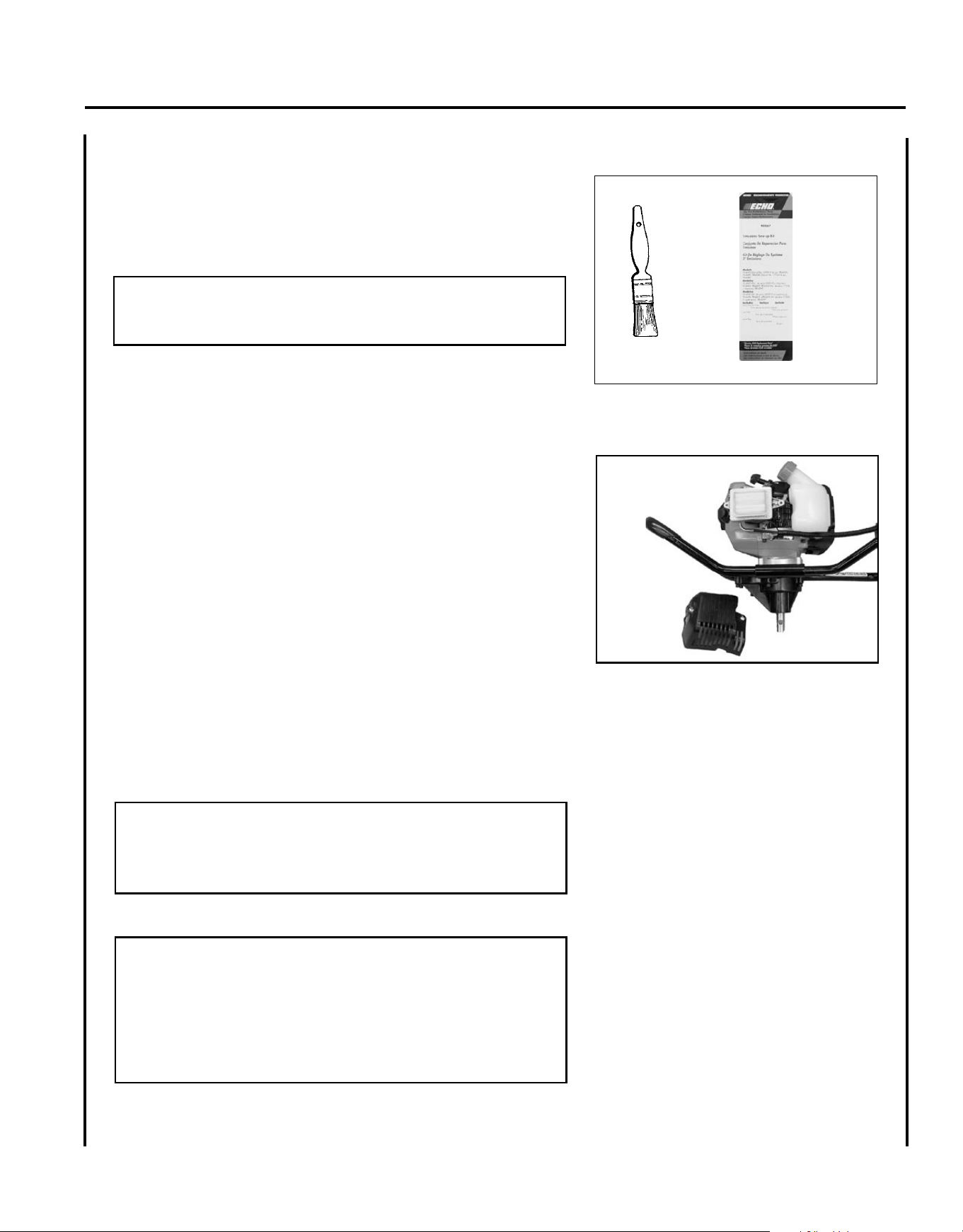
a I r f I l t e r
Level 1.
Tools required: 25 - 50mm (1 - 2 in.) cleaning brush
Parts required: REPOWER
TM
Tune-Up Kit
NOTE
Always brush dirt and debris away from air cleaner area prior to
cleaning air lter.
1. Brush dirt off air cleaner area. Keep dirt away from engine and air
intake grid.
2. Remove air lter cover. Brush dirt from inside cover and away
from edges of air lter.
3. Check air lter seal for tight t with air lter case.
4. Remove air lter from case. Use care to prevent dirt and debris
from falling into air lter case.
5. Inspect lter element and seal. Replace lter if any of these prob-
lems are present:
•Air lter seal does not t tightly against case
•Air lter seal is distorted, worn, or damaged
•Air lter element has holes or other damage
•Air lter element is saturated with dirt
•Air lter element is soaked with fuel mix
6. If air lter is in good condition and can be cleaned and reused,
lightly brush debris from air lter element, or blow lter element
clean using low pressure (40 psi or less) compressed air directed at
inside of lter.
IMPORTANT
When using compressed air, always direct air stream at inside sur-
face of lter so dust and debris will be blown out of lter. Keep air
nozzle 6 - 8 inches away from lter to prevent damage to lter.
7. Install air lter in case, and replace cover.
NOTICE
Actual replacement interval for air lter depends on operating con-
ditions. Operation in dustier applications requires more frequent
cleaning and replacement. Continued operation with a damaged
or excessively dirty lter will allow dirt and debris to enter engine,
and result in poor performance, rapid engine wear, and premature
engine failure.
18
f u e l f I l t e r
Level 1.
Tools required: 200- 250 mm (8 - 10 in.) length of wire with one
end bent into a hook, clean rag, funnel, and an ap-
proved fuel container.
Parts required: REPOWER
TM
Tune-Up Kit
DANGER
Fuel is VERy ammable. Use extreme care when mixing, storing
or handling.
1. Use a clean rag to remove loose dirt from around fuel cap and
empty fuel tank.
2. Use the “fuel line hook” to pull the fuel line and lter from the
tank.
3. Remove the lter from the line and install the new lter.
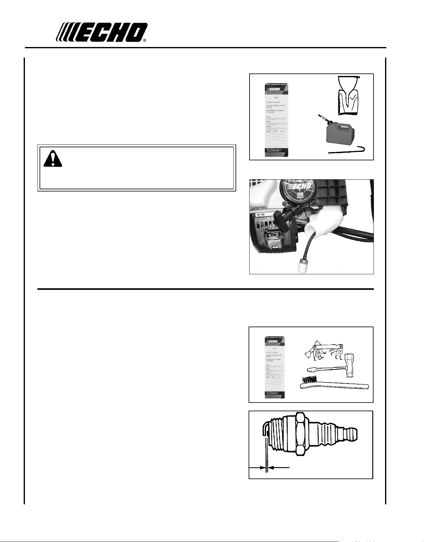
s p a r k p l u g
Level 2.
Tools Required: Spark plug wrench, feeler gauge, soft metal brush.
Parts Required: REPOWER
TM
Tune-Up Kit
1. Remove spark plug and check for fouling, worn and rounded
center electrode.
2. Clean the plug or replace with a new one. DO NOT sand blast to
clean. Remaining sand will damage engine.
3. Adjust spark plug gap by bending outer electrode.
4. Install Spark Plug, and tighten to 150-170 kgf • cm
(130-150 in. • lbf).
0.65 mm
(0.026 in.)
Ea r t h au g E r
Op E r a t O r 's Ma n u a l
19
c o o l I n g s y s t e m
Level 2.
Tools required: Air compressor and safety nozzle, or: 4 mm Hex
wrench, 25 - 50 mm (1 - 2 in.) cleaning brush.
Parts Required: None.
IMPORTANT
To maintain proper engine operating temperatures, cooling air
must pass freely through the cylinder n area. This ow of air
carries combustion heat away from the engine.
Overheating and engine seizure can occur when:
• Air intakes are blocked, preventing cooling air from reaching the
cylinder.
• Dust and debris build-up on the outside of the cylinder. This build-up
insulates the engine and prevents the heat from leaving.
Removal of cooling passage blockages and cleaning of cooling ns is
considered “Normal Maintenance.” Any failure attributed to lack of
maintenance is not warranted.
1. Periodically blow dirt and debris off cooling ns with a compressor
and safety nozzle, or;
2. Remove engine and mufer covers, and brush off dirt and debris
using the medium bristle brush.
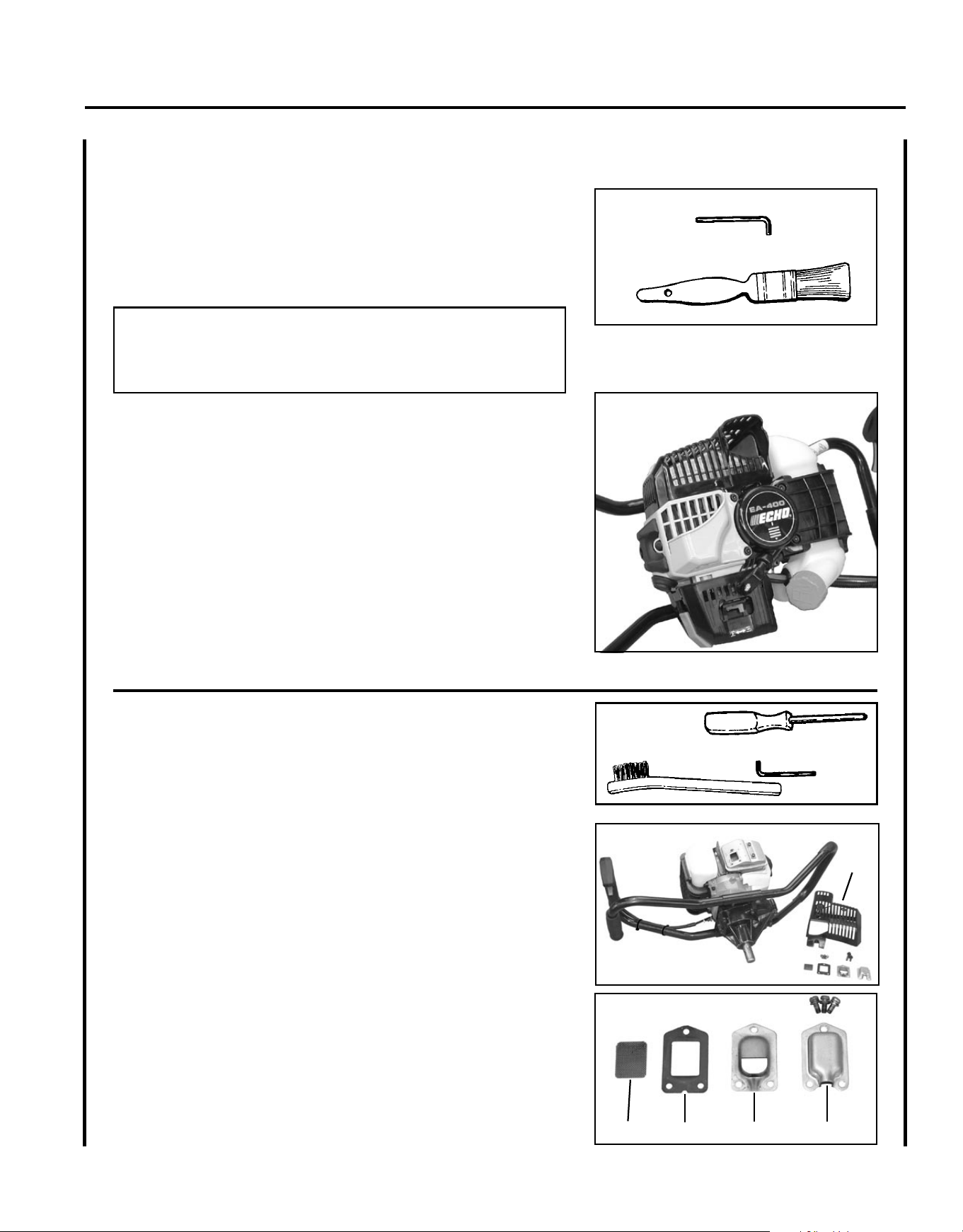
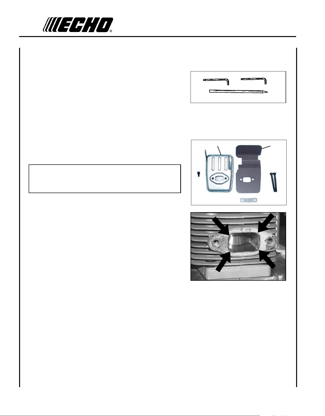
e X h a u s t s y s t e m
Spark Arrestor Screen
Level 2.
Tools Required: Cross Head Screwdriver, Soft Metal Brush, 4 mm
Hex Wrench
Parts Required: Spark Arrestor Screen, Gasket
1. Remove mufer cover (A).
2. Place piston at Top Dead Center (TDC) to prevent carbon/dirt from
entering cylinder.
3. Remove spark arrestor screen cover (B), screen holder (C), gasket
(D), and screen (E), from mufer body.
4. Clean carbon deposits from mufer components.
5. Replace screen if it is cracked, plugged, or has holes burned
through.
6. Assemble components in reverse order.
B
C
DE
A
20
Exhaust Port Cleaning
Level 2.
Tools required: 4 & 5 mm Hex Wrench, Wood or plastic scraper
Parts Required: As needed: Heat Shield
1. Remove spark plug lead from spark plug, and remove mufer
cover (2 screws).
2. Place piston at top dead center. Remove mufer (A) and heat
shield (B).
3. Use a wood or plastic scraping tool to clean deposits from cylinder
exhaust port.
IMPORTANT
Never use a metal tool to scrape carbon from the exhaust port.
Do not scratch the cylinder or piston when cleaning the exhaust
port. Do not allow carbon particles to enter the cylinder.
4. Inspect heat shield, and replace if damaged.
5. Install heat shield and mufer.
6. Tighten mufer mounting bolts (or nuts) to 95-130 in•lbf (110-
150 kgf•cm).
7. Attach spark plug lead and install mufer cover.
8. Start engine, and warm to operating temperature.
9. Stop engine, and re-tighten mounting bolts (or nuts) to specica-
tions.
A
B
Ea r t h au g E r
Op E r a t O r 's Ma n u a l
21
c a r b u r e t o r a d j u s t m e n t
Engine Break-In
New engines must be operated a minimum duration of two tanks of fuel
break-in before carburetor adjustments can be made. During the break-
in period your engine performance will increase and exhaust emissions
will stabilize. Idle speed can be adjusted as required.
High Altitude Operation
This engine has been factory adjusted to maintain satisfactory starting,
emission, and durability performance up to 1,100 feet above sea level
(ASL) (96.0 kPa). To maintain proper engine operation and emission
compliance above 1,100 feet ASL the carburetor may need to be ad-
justed by an authorized ECHO service dealer.
IMPORTANT
If the engine is adjusted for operation above 1,100 feet ASL, the
carburetor must be re-adjusted when operating the engine below
1,100 feet ASL, otherwise severe engine damage may result.
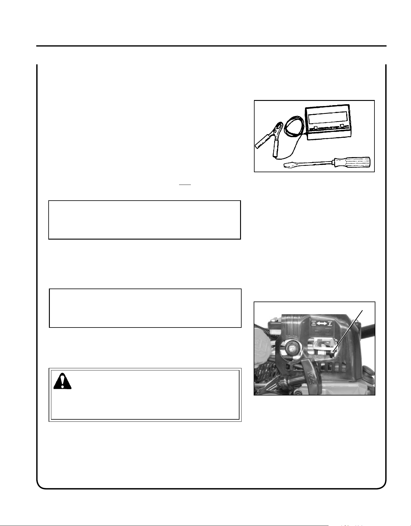
Level 2.
Tools required: Screwdriver, Tachometer (ECHO P/N
99051130017).
Parts required: None.
NOTE
Every unit is run at the factory and the carburetor is set in compli-
ance with emission regulations. This carburetor does not have accel-
eration and high speed adjustment needles.
1. Check idle speed and reset if necessary. Idle speed screw (A)
should be set to the specications found on page 24, "Specica-
tions" of this manual. Turn idle screw (A) clockwise to increase
idle speed; counter-clockwise to decrease idle speed.
WARNING
When carburetor adjustment is completed, the cutting attachment
should not turn at idle, otherwise serious personal injury may
result.
A
22
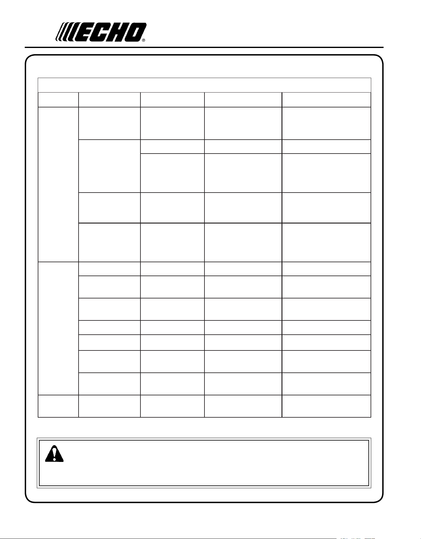
tr o u b l e s h o o t I n g
DANGER
Fuel vapors are extremely ammable and may cause re and/or explosion. Never test for ignition spark by
grounding spark plug near cylinder plug hole, otherwise serious personal injury may result.
TRAHCGNITOOHSELBUORTMELBORPENIGNE
melborPkcehCsutatSesuaCydemeR
enignE
-sknarc
/drahstrats
t'nseod
trats
roterubractaleuFroterubractaleufoNdeggolcreniartsleuF
deggolcenilleuF
roterubraC
ecalperronaelC
ecalperronaelC
relaedohcEruoyeeS
rednilyctaleuFrednilyctaleufoNroterubraCrelaedohcEruoyeeS
leufhtiwtewrelffuMhcirooterutxiMleuFekohcnepO
retlifriaecalper/naelC
roterubractsujdA
relaedohcEruoyeeS
dnetakrapS
eriwgulpfo
krapsoNffohcti
wspotS
melborplacirtcelE
hctiwskcolretnI
NOothctiwsnruT
relaedohcEruoyeeS
relaedohcEruoyeeS
gulptakrapSkrapsoNtcerrocnipagkrapS
nobrachtiwderevoC
leufhtiwdeluoF
evitcefedgulP
).ni620.0(mm56.ottsujdA
ecalperronaelC
ecalperronaelC
gulpecalpeR
,snurenignE
roseidtub
tonseod
etarelecca
ylreporp
retlifriAytridretlifriAraewlamroNecalperronaelC
retlifleuFytridretlifleuFseudiser/stnanimatnoCni
leuf
ecalpeR
tnevleuFdeggulptnevleuFniseudise
r/stnanimatnoC
leuf
ecalperronaelC
gulPkrapSnrow/ytridgulPraewlamroNecalperrotsujdadnanaelC
roterubraCtnemtsujdareporpmInoitarbiVtsujdA
metsySgnilooCmetsysgnilooC
deggulp/ytrid
ninoitarepodednetxE
snoitacolytsud/ytrid
naelC
rotserrAkrapS
neercS
rotserrakrapS
deggulpneercs
raewlamroNecalpeR
seodenignE
knarcton
A/NA/NmelborpenignelanretnIrelaedohcEruoyeeS
Ea r t h au g E r
Op E r a t O r 's Ma n u a l
23
st o r a g e
Long Term Storage (over 30 days)
WARNING
During operation the mufer or catalytic mufer and surrounding cover become hot. Always keep exhaust area clear
of ammable debris during transportation or when storing, otherwise serious property damage or personal injury may
result.
2. Place the stop switch in the "STOP" position.
3. Remove accumulation of grease, oil, dirt, and debris
from exterior of unit and accessory augers.
4. Perform all periodic lubrication and services that are
required.
5. Tighten all the screws and nuts.
6. Drain the fuel tank completely, and pull the recoil
starter handle several times to remove fuel from the
carburetor.
7. Remove the spark plug and pour 7 cc (1/4 oz.) of
fresh, clean, two-stroke engine oil into the cylinder
through the spark plug hole.
A. Place a clean cloth over the spark plug hole.
B. Pull the recoil starter handle 2-3 times to
distribute the oil inside the engine.
C. Observe the piston location through the
spark plug hole. Pull the recoil starter
handle slowly until the piston reaches the
top of its travel and leave it there.
8. Install the spark plug (do not connect ignition
cable).
Do not store your unit for a prolonged period of time (30 days or longer) without performing protective storage
maintenance which includes the following:
1. Store unit in a dry, dust free place, out of the reach of children.
DANGER
Do not store in enclosure where fuel fumes may accumulate or reach an open ame or spark.

24
sp e c I f I c a t I o n s
MODELs---------------------------------------------- EA-410
Length -------------------------------------------------- 585 mm (23 in.)
Width --------------------------------------------------- 270 mm (10.6 in.)
Height -------------------------------------------------- 370 mm (14.6 in.)
Weight -------------------------------------------------- 9.8 kg (21.6 lb.)
Engine Type ------------------------------------------- Air cooled, two-stroke, single cylinder gasoline engine
Bore ---------------------------------------------------- 40.0 mm (1.58 in.)
Stroke --------------------------------------------------- 34.0 mm (1.34 in.)
Displacement ----------------------------------------- 42.7 cc (2.61 cu. in.)
Exhaust ------------------------------------------------- Spark arrestor mufer or spark arrestor mufer with catalyst
Carburetor---------------------------------------------- Walbro diaphragm model w/purge pump
Ignition System --------------------------------------- Flywheel magneto, capacitor discharge (CDI)
Spark Plug --------------------------------------------- NGK BPM-7A, (Gap 0.65 mm (0.026 in.)
Fuel ----------------------------------------------------- Mixed (Gasoline and Two-stroke Oil)
Fuel/Oil Ratio ----------------------------------------- 50 : 1 Power Blend X™ ISO-L-EGD (ISO/CD 13738) and J.A.S.O.
M345- FC/FD, two-stroke, air-cooled engine oil.
Gasoline ------------------------------------------------ Use 89 Octane unleaded. Do not use fuel containing methyl alcohol,
more than 10% ethyl alcohol or 15% MTBE. Do not use alternative
fuels such as E-15 or E-85.
Oil ------------------------------------------------------- Power Blend
TM
Premium Universal 2-Stroke Oil
Fuel Tank Capacity ----------------------------------- 1.0 lit. (33.8 US . oz.)
Starter System ----------------------------------------- Automatic Recoil Starter
Clutch--------------------------------------------------- Centrifugal Type
Vibration Isolation System -------------------------- Cushioned left and right hand grips
PTO Shaft ---------------------------------------------- 22 mm (.875 in.) Diameter
Gear Case Ratio --------------------------------------- 30.2:1 Reduction
Auger Capacity ---------------------------------------- 51mm - 254 mm (2 in. - 10 in.)
Rotation ------------------------------------------------ Clockwise, viewed from top
Handle -------------------------------------------------- Cushioned Bow w/Grip
Idle Speed ---------------------------------------------- 2,500 RPM
Clutch Engagement Speed --------------------------- 3,600 RPM
Wide Open Throttle Speed (W.O.T.) -------------- 9,800 - 11,500 RPM

Ea r t h au g E r
Op E r a t O r 's Ma n u a l
25
au g e r ac c e s s o r I e s
Earth Augers* Part Number Description
99944900150 2" Earth Auger w/point
99944900160 3" Earth Auger w/point
99944900170 4" Earth Auger w/point
99944900180 6" Earth Auger w/point & Spring
99944900190 8" Earth Auger w/point & Spring
99944900200 10" Earth Auger w/point & Spring
Extension Shafts* 99944900210 18" Extension Shaft - 7/8" Diameter
99944900220 12" Extension Shaft - 7/8" Diameter
Earth Auger Replacement Blades* 99944900230 4" Replacement Blade - Earth Auger
99944900240 6" Replacement Blade - Earth Auger
99944900250 8" Replacement Blade - Earth Auger
99944900260 10" Replacement Blade - Earth Auger
99944900270 2" Replacement Point - Earth Auger
99944900370 1" Replacement Point - Earth Auger
Ice Augers* 99944900275 Replacement Point - Ice Auger
99944900280 8" Ice Auger - Dual Blade
99944900290 10" Ice Auger - Dual Blade
Ice Auger Replacement Blades* 99944900300 8" Replacement Blade - Ice Auger
99944900310 10" Replacement Blade - Ice Auger
Auger Adaptor 99944900335 Auger Adapter for 1" Auger mount
* All auger accessories include required assembly hardware.
26
ECHO LIMITED WARRANTY STATEMENT FOR
PRODUCT SOLD IN USA AND CANADA BEGINNING 01/01/2010
ECHO'S RESPONSIBILITY
ECHO Incorporated’s Limited Warranty, provides to the original purchaser that this ECHO product is free from defects in material and workmanship.
Under normal use and maintenance from date of purchase, ECHO agrees to repair or replace at ECHO’s discretion, any defective product
free of charge at any authorized ECHO servicing dealer within listed below application time periods, limitations and exclusions. THIS LIMITED
WARRANTY IS ONLY APPLICABLE TO ECHO PRODUCTS SOLD BY AUTHORIZED ECHO DEALERS. IT IS EXTENDED TO THE ORIGINAL
PURCHASER ONLY, AND IS NOT TRANSFERABLE TO SUBSEQUENT OWNERS EXCEPT FOR EMISSION RELATED PARTS. Repair
parts and accessories replaced under this warranty are warranted only for the balance of the original unit or accessory warranty period. Any
damage caused by improper installation or improper maintenance is not covered by this warranty. All parts or products replaced under warranty
become the property of ECHO, Inc. This warranty is separate from the Emission control warranty statement supplied with your new product.
Please consult the Emission Control Warranty Statement for details regarding emission related parts. For a list of Authorized ECHO Dealers
refer to WWW.ECHO-USA.COM or call 1-800-432-ECHO.
OWNER’S RESPONSIBILITY
To ensure trouble free warranty coverage it is important that you register your ECHO equipment on-line at WWW.ECHO-USA.COM or by ll-
ing out the warranty registration card supplied with your unit. Registering your product conrms your warranty coverage and provides a direct
link if we nd it necessary to contact you.
The owner shall demonstrate reasonable care and use, and follow preventative maintenance, storage, fuel and oil usage as prescribed in the
operator’s manual. Should a product difculty occur, you must, at your expense, deliver or ship your ECHO unit to an authorized ECHO servicing
dealer for warranty repairs (within the applicable warranty period), and arrange for pick-up or return of your unit after the repairs have been
made. For your nearest authorized ECHO servicing dealer, call ECHO’s Dealer Referral Center, at 1-800-432-ECHO or you can locate an ECHO
servicing dealer at WWW.ECHO-USA.COM. Should you require assistance or have questions concerning ECHO’s Warranty Statement, you
can contact our Consumer Product Support Department at 1-800-673-1558 or contact us through the web at WWW.ECHO-USA.COM.
PRODUCT WARRANTY PERIOD
RESIDENTIAL APPLICATION
• 5 YEAR WARRANTY - All units for residential, or non-income producing use will be covered by this limited warranty for ve (5) years from
date of purchase.
EXCEPTIONS:
• For two-stroke engine powered products, the electronic ignition module, exible drive cables, SRM solid drive shafts, and TC tines
are warranted for the life* of the product on parts only.
• Cutting attachments such as, but not limited to, bars, chains, sprockets, blades, and nylon trimmer heads for residential or non-income
producing use will be covered for failures due to defects in material or workmanship for a period of 60 days from original product
purchase date. Any misuse from contact with concrete, rocks, or other structures is not covered by this warranty.
• ECHO’s Rapid Loader String Head carries a lifetime warranty on the line locking system, parts only; no labor. Refer to your operator’s
manual for string head installation and maintenance instructions.
• All SB-Series and PRO ATTACHMENT SERIES Split Shaft attachments carry the same warranty duration as the units they are
designed to t.
COMMERCIAL APPLICATION
• 1 YEAR WARRANTY - All Chain Saws, QuikVent Saws, and Cut-Off Saws for commercial, institutional, agricultural, industrial, or income
producing use will be covered by this limited warranty for one (1) year from the date of purchase.
• 2 YEAR WARRANTY - All other units for commercial, institutional, agricultural, industrial, or income producing use will be covered by this
limited warranty for two (2) years from the date of purchase.
EXCEPTIONS:
• For two-stroke engine powered products, the electronic ignition module, exible drive cables, SRM solid drive shafts and TC tines,
are warranted for the life* of the product on parts only.
• Cutting attachments such as, but not limited to, bars, chains, sprockets, blades, and nylon trimmer heads for commercial, institutional,
agricultural, industrial, rental, or income producing will be covered for failures due to defects in material or workmanship for a period
of 30 days from original product purchase date. Any misuse from contact with concrete, rocks, or other structures is not covered by
this warranty.
• ECHO’s Rapid Loader String Head carries a lifetime warranty on the line locking system, parts only; no labor. Refer to your operator’s
manual for string head installation and maintenance instructions.
• All SB-Series and PRO ATTACHMENT SERIES Split Shaft attachments carry the same warranty duration as the units they are
designed to t.
RENTAL APPLICATION - 90 DAYS WARRANTY
• Units for rental use will be covered against defects in material and workmanship for a period of 90 days from the date of purchase.
* ECHO’s liability under the “Lifetime” coverage is limited to furnishing parts specied under the PROdUCT wARRANTy PERIOd section of
this warranty statement for “Life” free of charge for a period of ten (10) years after the date of the complete unit’s nal production.
wa r r a n t y st a t e m e n t s

Ea r t h au g E r
Op E r a t O r 's Ma n u a l
27
PURCHASED REPAIR PARTS, SHORT BLOCKS AND ACCESSORIES
• 90-day residential, or non-income producing warranty
• 30-day commercial, institutional, agricultural, industrial, income producing, or rental application warranty
ATTENTION TWO-STROKE ENGINE POWER PRODUCT OWNERS
This ECHO two-stroke engine power product is a quality-engineered unit which has been manufactured to exact tolerances to provide superior
performance. To help ensure the performance of the unit, it is required to use two-stroke oil which meets the ISO-L-EGD Standard per ISO/CD
13738 and JASO M345/FC/FD Standards. ECHO Power Blend™ Two-Stroke Oil is a premium two-stroke oil specically formulated to meet
ISO-L-EGD (ISO/CD 13738) and JASO M345/FC/FD Standards. The use of two-stroke oils designed for other applications, such as for outboard
motors or lawnmowers can result in severe engine damage, and will void your two-stroke engine limited warranty.
THIS WARRANTY DOES NOT COVER DAMAGE CAUSED BY:
• Lack of lubrication or engine failure, due to the use of two-stroke oils that do not meet the ISO-L-EGD (ISO/CD 13738) and JASO M345/
FC/FD Standards. Engine problems due to inadequate lubrication caused by failure to use an ISO-L-EGD compliant and JASO M345/FC/
FD registered oil, will void the two-stroke engine limited warranty. ECHO Power Blend™ Two-Stroke Oil meets the ISO-L-EGD and JASO
M345/FC/FD Standard. Emission related parts are covered for 5 years residential use or 2 years commercial use regardless of two-stroke
oil used, per the statement listed in the EPA or California Emission Defect Warranty Explanation.
• damage caused by use of gasohol, containing methanol (wood alcohol), or gasoline containing less than 89 octane. Only use gasoline which
contains 89 octane or higher. Gasohol which contains a maximum 10% ethanol (grain alcohol) or 15% MTBE (methyl/tertiary/butyl/ether)
is also approved. The prescribed mixing ratio of gasoline to oil is listed on the ECHO oil label and covered in your operator’s manual.
• Engine damage caused by use of ether or any starting uids.
• damage caused by tampering with engine speed governor or emission components, or running engines above specied and recommended
engine speeds as listed in your operator’s manual.
• Operation of the unit with improperly maintained/removed cutting shield or removed/damaged air lter.
• damage caused by dirt, pressure or steam cleaning the unit, salt water, corrosion, rust, varnish, abrasives, and moisture.
• defects, malfunctions or failures resulting from abuse, misuse, neglect, modications, alterations, normal wear, improper servicing, or use
of unauthorized attachments.
• Incorrect storage procedures, stale fuel, including failure to provide or perform required maintenance services as prescribed in the operator's
manual. Preventative maintenance as outlined in the operators manual is the customer’s responsibility.
• Failures due to improper set-up, pre-delivery service or repair service by anyone other than authorized ECHO servicing dealer during the
warranty period.
• Certain parts and other items are not warranted, including but not limited to: lubricants, starter cords, and engine tune-ups.
• Use of spark plugs other than those meeting performance and durability requirements of the OEM spark plug listed in the Operator's
Manuals.
• Overheating or carbon scoring failures due to restricted, clogged exhaust port or combustion chamber, including damage to spark arrester
screen.
• Adjustments after the rst (30) thirty days and beyond, such as carburetor adjustment and throttle cable adjustment.
• damage to gears or gear cases caused by contaminated grease or oil, use of incorrect type or viscosity of lubricants, and/or failure to comply
with recommended grease or oil change intervals.
• damage caused by loading SHREd 'N' VAC
®
beyond recommended capacity.
• damage caused by pump or sprayer running dry, pumping or spraying caustic or ammable materials, or lack of or broken strainers.
• Additional damage to parts or components due to continued use after operational problem or failure occurs. Should operational problem or
failure occur, the product should not be used, but delivered as is to an authorized ECHO servicing dealer.
It is a dealer’s and/or customer’s responsibility to complete and return the warranty registration card supplied with your ECHO product or by visiting
WWW.ECHO-USA.COM. your receipt of purchase including date, model and serial number must be maintained and presented to an authorized
ECHO servicing dealer for warranty service. Proof of purchase rests solely with the customer. Some states do not allow limitations on how long
an implied warranty lasts, so the above limitations may not apply to you. Some states do not allow the exclusion or limitation of incidental or
consequential damages, so you may also have other specic legal rights which vary from state to state. This limited warranty is given by ECHO
Incorporated, 400 Oakwood Rd., Lake Zurich, IL 60047.
DISCLAIMER OF IMPLIED WARRANTIES
This limited warranty is in lieu of all other expressed or implied warranties, including any warranty of FITNESS FOR A PARTICULAR PURPOSE
OR USE and any implied warranty of MERCHANTABILITY otherwise applicable to this product. ECHO and its afliated companies shall not be
liable for any special incidental or consequential damage, including lost prots. There are no warranties extended other than as provided herein.
This limited warranty may be modied only by ECHO.
99922201032
12/03/09

28
ECHO INCORPORATED EMISSION CONTROL WARRANTY STATEMENT
FOR ECHO AND SHINDAIWA BRANDS
The Environmental Protection Agency (EPA) and the California Air Resources Board (C.A.R.B.) and ECHO Incorporated (ECHO Inc.) are pleased
to explain the emission control system warranty on your 2010 and later equipment/small off-road engine (SORE). New equipment/SORE must be
designed, built and equipped to meet stringent EPA and C.A.R.B. anti-smog standards. ECHO Inc. must warrant the emission control system on
your equipment/SORE for the periods of time listed below, provided there has been no abuse, neglect or improper maintenance of your equipment/
SORE. Your emission control system may include parts such as: carburetor, fuel-injection system, ignition system, catalytic converter/mufer, fuel
tank, fuel feed lines, fuel cap assembly, spark plug, air lters, and other associated components. Where a warrantable condition exists, ECHO
Inc will repair your equipment/SORE at no cost to you including diagnosis, parts and labor. The Emission Control System warranty is extended
to the original owner including all subsequent owners.
MANUFACTURER'S WARRANTY COVERAGE:
The emission control system is warranted for 2 years or the length of the ECHO Inc. warranty, whichever is longer. If any emission-related part
on your equipment is defective, the part will be repaired or replaced by ECHO Inc. or its Authorized Service Representative.
OWNER'S WARRANTY RESPONSIBILITIES:
As the equipment/SORE owner, you are responsible for the performance of the required maintenance listed in your Operator's Manual. ECHO
Inc. recommends that you retain all receipts covering maintenance on your equipment/SORE however, ECHO Inc. cannot deny warranty solely
for the lack of receipts or for your failure to ensure the performance of all scheduled maintenance. As the equipment/SORE owner, you should be
aware that ECHO Inc. may deny you warranty coverage if your equipment/SORE or a part has failed due to abuse, neglect, improper maintenance
or unapproved modications.
You are responsible for presenting your equipment/SORE to an ECHO Inc. authorized service representative as soon as a problem exists. The
warranty repairs should be completed in a reasonable amount of time, not to exceed 30 days. If a warrantable condition exists and there is no
Authorized Dealer within 100 miles, ECHO Inc. will pay to ship the unit to the nearest authorized dealer. If you have questions regarding your
warranty coverage, you should contact ECHO Inc. at 1-800-673-1558, web site WWW.ECHO-USA.COM or contact Shindaiwa at 1-877-986-
7783, web site WWW.SHINDAIWA.COM.
WHAT DOES THIS WARRANTY COVER?
ECHO Inc. warrants that your equipment/SORE was designed, built and equipped to conform with applicable EPA and C.A.R.B. emissions
standards and that your equipment/SORE is free from defects in material and workmanship that would cause it to fail to conform with applicable
requirements for 2 years or the length of the ECHO Inc. warranty, whichever is longer. The warranty period begins on the date the product is
purchased by an end user.
HOW WILL A COVERED PART BE CORRECTED?
If there is a defect in a part covered by this warranty, any ECHO Inc. Authorized Service Dealer will correct the defect. You will not have to pay
anything to have the part adjusted, repaired or replaced. This includes any labor and diagnosis for warranted repairs performed by the dealer. In
addition, engine parts not expressly covered under this warranty but whose failure is a result of a failure of a covered part will be warranted.
WHAT PARTS ARE COVERED?
Any applicable emission related part not scheduled for "required maintenance" will be repaired or replaced within the warranty period. The repaired
or replaced part will be warranted for the remaining ECHO Inc. warranty period.
Any warranted part that is scheduled only for regular inspection in the written instructions supplied is warranted for the warranty period stated
above. Any such part repaired or replaced under warranty will be warranted for the remaining ECHO Inc. warranty period.
Any emission related part scheduled for replacement during "required maintenance" is warranted for the period of time prior to the rst scheduled
replacement point for that part. Any such part repaired or replaced under warranty shall be warranted for the remainder of the period prior to the
rst scheduled replacement point for that part.
Any manufacturer-approved replacement part may be used in the performance of any warranty maintenance or repairs on emission related parts,
and must be provided without charge if the part is still under warranty.
Any replacement part that is equivalent in performance and durability may be used in non-warranty maintenance or repairs, and shall not reduce
the warranty obligations of the manufacturer.
Throughout the equipment/SORE warranty period, ECHO Inc. will maintain a supply of warranted parts sufcient to meet the expected demand
for such parts.
SPECIFIC EMISSION RELATED WARRANTED PARTS:
• Electronic Ignition System • Spark Plug
• Catalytic Converter / Mufer Assembly • Carburetor (complete assembly or replaceable components)
• Choke • Fuel-Injection Assembly (or replaceable components)
• Fuel Tank • Fuel Cap Assembly
• Air Filter • Fuel Feed Line (and associated clamps/connectors as applicable)
WHAT IS NOT COVERED?
Any failure caused by abuse, neglect, improper maintenance, unapproved modications, use of unapproved add-on parts/modied parts or
unapproved accessories.
This Emission Control Warranty is valid only for the U.S.A., it's Territories, and Canada.
99922201033
01/2010

Ea r t h au g E r
Op E r a t O r 's Ma n u a l
29
n o t e s

30
n o t e s

Ea r t h au g E r
Op E r a t O r 's Ma n u a l
31
n o t e s
ECHO, INCORPORATED
400 oa k w o o d ro a d
la k e Zu r I c h , Il 60047
www.echo-usa.com
DEALER?
CALL
1-800-432-ECHO
OR
www.echo-usa.com
CONSUMER PRODUCT
SUPPORT
1-800-673-1558
8:30 - 4:30 MON - FRI C.S.T.
S05503001001/S05503999999
se r v I c I n g In f o r m a t I o n
p a r t s
/s e r I a l n u m b e r
Genuine ECHO Parts and ECHO REPOWER™ Parts and Assemblies
for your ECHO products are available only from an Authorized ECHO
Dealer. When you do need to buy parts always have the Model Num-
ber, Type and Serial Number of the unit with you. You can nd these
numbers on the engine housing. For future reference, write them in the
space provided below.
Model No. _________________SN. ___________________
s e r v I c e
Service of this product during the warranty period must be performed
by an Authorized ECHO Service Dealer. For the name and address of
the Authorized ECHO Service Dealer nearest you, ask your retailer or
call: 1-800-432-ECHO (3246). Dealer information is also available on
our Web Site. When presenting your unit for Warranty service/repairs,
proof of purchase is required.
e c h o c o n s u m e r p r o d u c t s u p p o r t
If you require assistance or have questions concerning the applica-
tion, operation or maintenance of this product you may call the ECHO
Consumer Product Support Department at 1-800-673-1558 from 8:30
am to 4:30 pm (Central Standard Time) Monday through Friday. Before
calling, please know the model and serial number of your unit.
w a r r a n t y r e g I s t r a t I o n
To ensure trouble free warranty coverage it is important that you regis-
ter your ECHO equipment on-line at www.echo-usa.com or by lling
out the warranty registration card supplied with your unit. Registering
your product conrms your warranty coverage and provides a direct
link between you and ECHO if we nd it necessary to contact you.
a d d I t I o n a l o r r e p l a c e m e n t m a n u a l s
Replacement Operator, safety Manuals, and Parts Catalogs are available from your ECHO dealer or at www.echo-
usa.com or by contacting ECHO Inc., 400 Oakwood Road, Lake Zurich, IL 60047 (800-673-1558). Always check the
ECHO Web Site for updated information.
safety Videos are available from your Echo dealer. A $5.00 shipping charge will be required for each video.