Owner’s Manual
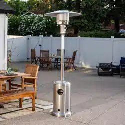
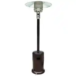
Canyon Ridge™ Rapid Induction Area Heater™
Item# 66854
Lowe’s# 749294
SERIES
WARNING
Improper installation, adjustment, alteration, service or maintenance can cause injury or
property damage. Read the owner’s manual thoroughly before installing or servicing this
equipment. If the information in this manual is not followed exactly, a re or explosion may
result causing property damage, personal injury or loss of life.
Save these instructions for future use. If you are
assembling this unit for someone else, give this
manual to him or her and read and save for the
future.
DANGER
WARNING
WARNING
If you smell gas:
1. Shut off gas to the appliance.
2. Extinguish any open ame.
3. If odor continues, keep away from
the appliance and immediately call
your gas supplier or re department.
Do not store or use gasoline or other
ammable vapors and liquids in the
vicinity of this or any other appliance.
An LP-cylinder not connected for use
shall not be stored in the vicinity of
this or any other appliance.
For outdoor use only.

Bond Manufacturing Company | Page 2
WARNING
Before you assemble or operate this unit, please carefully read this entire manual. Failure to do so
may result in a re, explosion, injury or death.
SAFETY INFORMATION
• The installation of this unit must adhere to local codes or either the National Fuel Gas Code, ANSI
Z223. 1/NFPA54, OR CAN/CGA-B149.1, National Gas and Propane Installation Code.
• THIS UNIT IS INTENDED FOR OUTDOOR USE ONLY! This product shall be used outdoors, in a
ventilated space and shall not be used in any enclosed area.
• This unit is to be used with propane gas only! (sold separately)
• Do not attach a remote gas supply to this unit.
• Only use propane gas for this unit.
• This unit is not intended for natural gas.
• Converting this unit to natural gas is dangerous and not recommended. The conversion of this unit
will void the manufacturer warranty.
• If the propane gas tank is leaking gas, you may hear, see, or smell a hiss. Do the following:
1. Disconnect the propane gas tank. 2. Do not attempt to x the problem yourself. 3. Contact your gas
supplier or re department for help.
• Never install or remove a propane tank from this unit while it is in use.
• Applying too much propane may result in gas pooling and will not burn. Allow fresh air into the unit
so that the remaining gas may escape.
• Do not use a ame to check for gas leaks.
• The max. inlet supply pressure: max. Gas supply 11 in w.c. (2.74kPa)
•
• You must use a propane tank that has a collar to protect the gas valve.
• DO NOT ll tank over 80 percent full.
• The tank system must be set up for vapor withdrawal.
• Discontinue use if any part of the propane tank is damaged. Rust and dents may be hazardous and
should be inspected by a gas supplier.
• Do not operate unit until all parts are fully assembled.
• Do not paint or color any part of this heating unit.
• Unit may be hot while in use, do not attempt to move it while in use.
• Never leave this heating unit unattended while in use.
• This unit is not intended for cooking.
• Keep any ammable items away.
• Keep a safe distance to avoid burning skin or clothing.
• Do not sit or rest hands or feet on this heating unit.
• Never place hands or ngers on upper portion of this unit while in use.
• Keep all electrical cords and fuel supply hose away from heated surfaces.
• Combustible materials should not be within 24 inches of the top of the unit, or within 24 inches
around the entire unit.
• Keep the appliance area clear and free from combustible material, gasoline and other ammable
vapors and liquids.
• Never use the unit in spaces which may contain volatile or airborne combustibles.
• If the ame goes out while burning, turn the gas valve off. Wait 5 minutes before repeating the initial
lighting procedure. Once you have a ame started, hold down the control knob for 1 minute.
• Do not add water into the unit.
• Do not operate unit if any part has been under water. Call a service technician to replace any
Use LP propane tanks with the following dimensions: diameter 12 in, height 18 in - capacity 20 lbs.

1-866-771-2663 | Page 3
damaged part should this occur.
• Do not disconnect any part while unit is in use.
• Do not store a spare propane tank on or near this unit.
• If the heating unit is indoors, detach the propane tank and leave outdoors.
• Do not operate on a boat or vehicle. This unit must be used on a at surface and outdoors ONLY.
• Always remove protective cover before operating (if applicable).
• Do not set the protective cover over the unit until it is turned off and completely cooled down.
• Check for leaks after not using the unit for long periods of time.
• Children should never operate this unit. Children must be supervised while near this unit.
• Keep gas tank at least 5 ft away from unit when lit. (if external tank)
• The maximum gas supply pressure is 250psi.
• All installation and repair should be done by a qualied professional. This unit should be
inspected annually and cleaned regularly.
• Inspect all elements of this heating unit before each use. If there is damage, the burner must be
replaced.
• Be aware of the hazards of high temperatures and stay away from the unit to avoid any burns or
injury.
• The gas supply tank should be constructed and marked with the specications for the LP gas tanks
of the U.S. Department of Transportation or the National Standard of Canada CAN/CSA-B339, LP gas
tanks, spheres and tubes for Transportation of Dangerous Goods; and Commission.
• The LP gas tank must have a listed overlling prevention device and a QCCI or Type I, (CGA810) LP
gas tank connection.
• This heating appliance should not be used on plastic or articial wood desks.
• Inspect the gas hose and all connections to the propane tank prior to each use.
• Always follow lighting instructions carefully.
• Do not use 30 lb. propane tanks for this unit.
• In case of high winds, secure this unit to the ground to prevent the unit falling over.
• Children and adults should be alerted to the hazards of high surface temperatures and should
stay away to avoid burns or clothing ignition.
• Young children should be carefully supervised when they are in the area of the appliance.
• Clothing or other ammable materials should not be hung from the appliance or placed on or
near the appliance.
• Any guard or other protective device removed for servicing the appliance shall be replaced
prior to operating the appliance.
• Installation and repair should be done by a qualied service person. The appliance should be
inspected before use and at least annually by a qualied service person. More frequent cleaning
may be required as necessary. It is imperative that the control compartment, burners and
circulating airways of the appliance are kept clean.
Only use the regulator and hose assembly provided with this unit. Replacement parts must be supplied
directly by Bond Manufacturing Co.
Inspect the burner before use of this unit. If the burner shows any kind of damage, do not operate
the appliance. For assistance with repair or replacement of the burner or any other parts, calls Bond
Manufacturing at 1.866.771.2663.
NOTE: You must follow all steps to properly assemble this heating item. Make sure the gas
valve is turned “OFF” before assembling. Do NOT attempt to assemble without proper tools.
Bond Manufacturing Company | Page 4
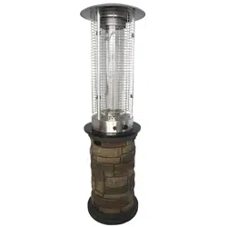
AA BB CC DD EE
FF
GG
Item Description Qty
AA M6 Cap Nut 3
BB M6 Nut 4
CC M8 Nut 3
DD M5 Wing Nut 3
EE M6 Studs 3
FF M8 Studs 3
GG Anchoring Nut 4
HARDWARE
Before beginning assembly of product, make sure all parts are present. Compare parts with package
contents list and hardware contents list. If any part appears missing or damaged, don't use this product
and call customer service immediately.
Estimated assembly time: 30 minutes.
Tools required for assembly (not included): Phillips Screwdriver, Wrench.
1-866-771-2663 | Page 5
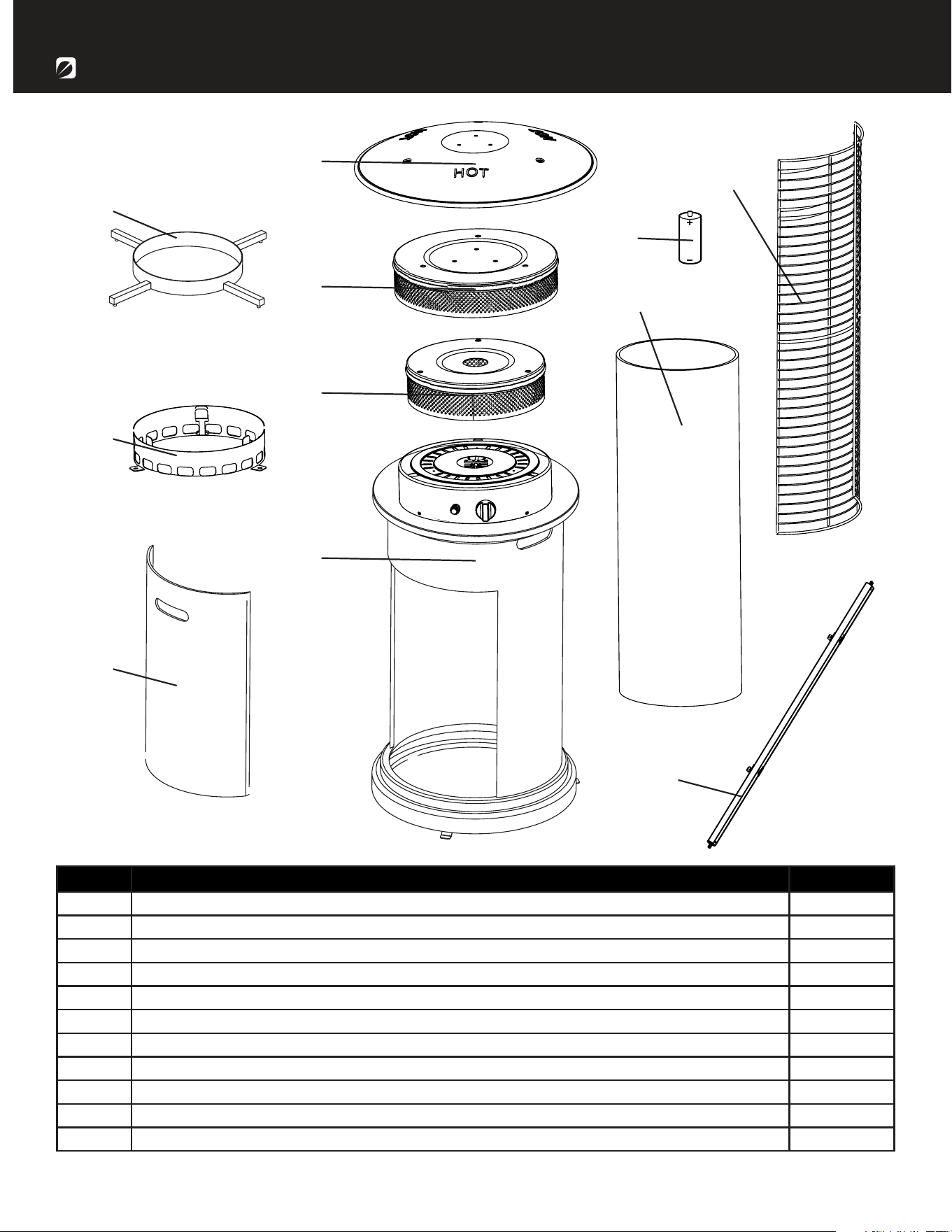
H
I
Item Description Qty
A Tank Supporter 1
B Glass Tube Ring 1
C Door 1
D Reflector 1
E Upper Radiation Screen 1
F Lower Radiation Screen 1
G Body 1
H Glass Tube 1
I Mesh Guard 3
J Upper Supporter 3
K Battery 1
CONTENTSCONTENTS
D
E
F
G
J
C
B
A
K
Bond Manufacturing Company | Page 6
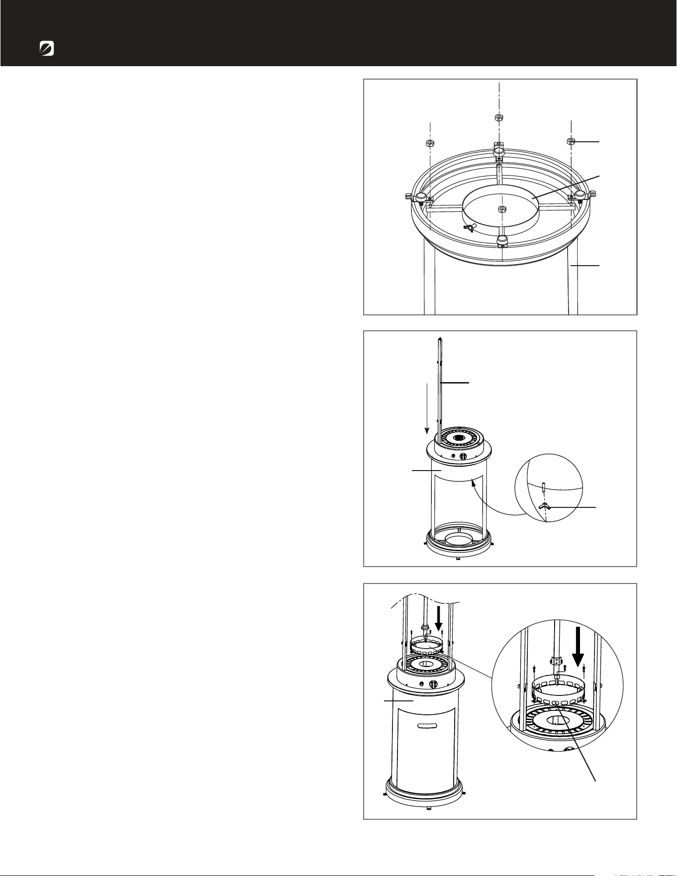
ASSEMBLY INSTRUCTIONS
1. Flip the body (G) upside down on a protected
surface. Remove the glass tube (H).
Attach the tank supporter (A) to the bottom of the
body (G) using 4 M6 nuts (BB). Flip the body (G)
over.
Note: Make sure the wing nut on the tank
supporter (A) faces the door on the body (G).
2. Slide the 3 upper supporters (J) into the slots
in the burner at the top of the body (G). Be sure
that they are fully inserted. Tighten the upper
supporters (J) with 3 M5 wing nuts (DD).
Note: Be sure that the hook on the upper
supporter is upwards.
3. Remove the 3 preassembled screws from the
burner at the top of the body (G). Attach the glass
tube ring (B) to the top of the burner using the 3
preassembled screws you just removed.
BB
DD
G
J
G
G
A
B
1-866-771-2663 | Page 7
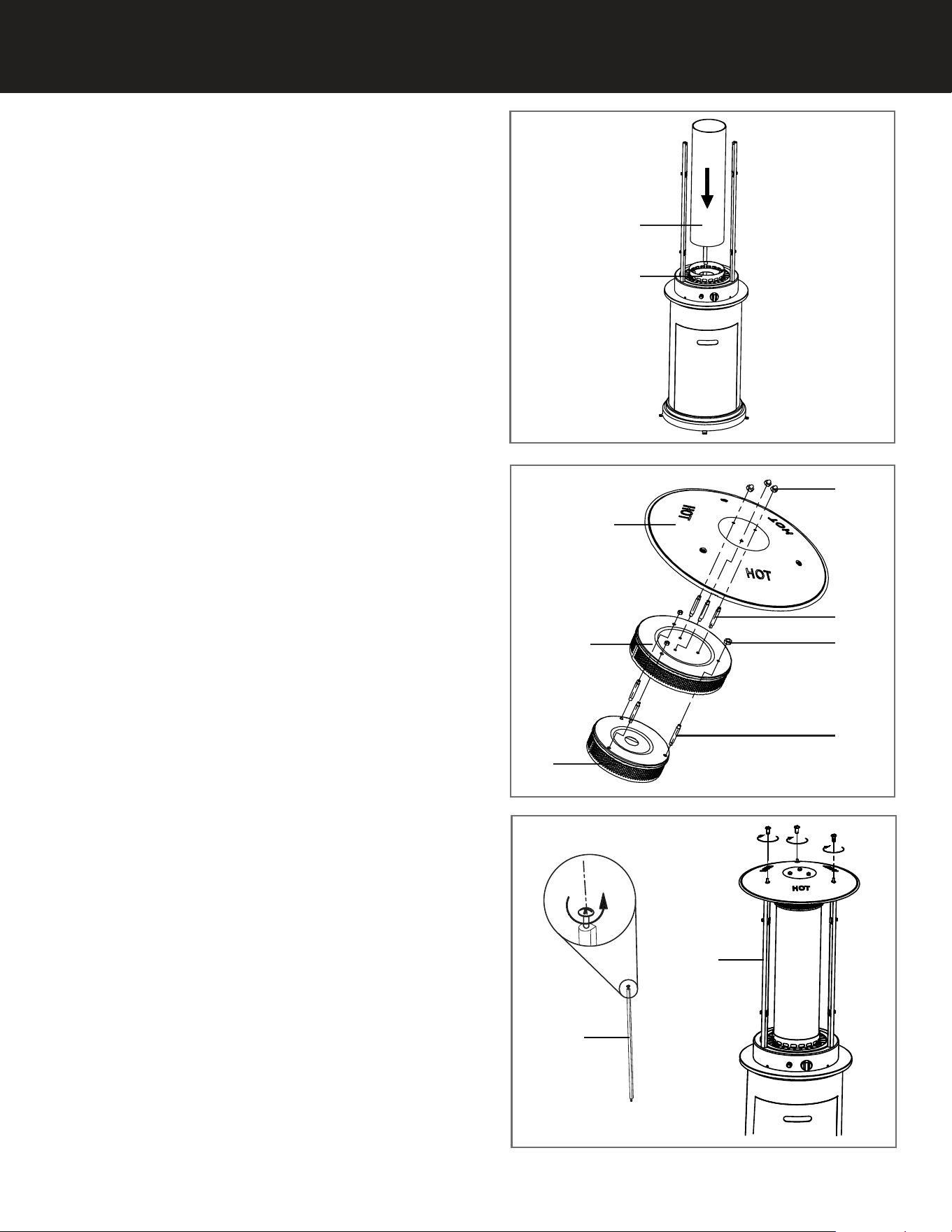
4. Place the glass tube (H) into the top of the glass
tube ring (B).
666... Remove 3 M5 screws from the upper
supporters (J). Place the reflector assembly made
in the previous step onto the upper supporters (J).
Tighten together with 3 M5 screws just removed
from the upper supporters (J).
5. Insert 3 M8 studs (FF) inbetween lower
radiation screen (F) and upper radiation screen (E).
Fasten the studs with 3 M8 nuts (CC). Then insert
3 M6 studs (EE) between the upper radiation
screen (E) and the reector (D). Fasten with 3 M6
cap nuts (AA).
B
H
F
E
D
AA
EE
CC
FF
J
J
Bond Manufacturing Company | Page 8
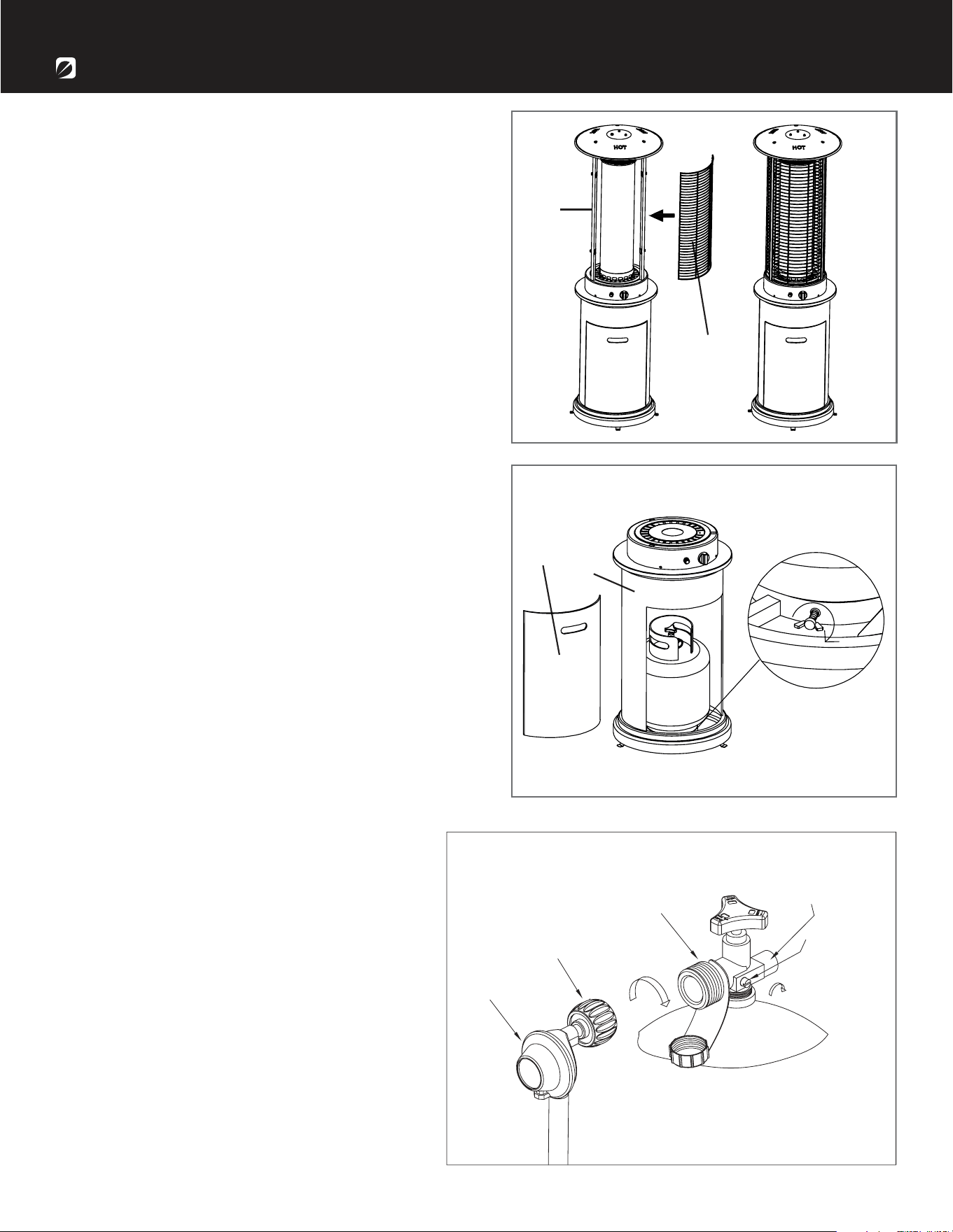
ASSEMBLY INSTRUCTIONS
7. Attach the 3 mesh guards (I) onto the hooks at
the top of the upper supporters (J).
8. Remove door (C) from body (G). Place the
propane gas tank (not included) into the tank
supporter. Tighten the preassembled wing screw
clockwise to ensure the propane tank is secure.
Replace the door after the tank is connected to
the regulator (see below).
J
C
G
I
CYLINDER VALVE
PRESSURE
RELIEF VALVE
BLEED-OFF
VALVE
BLACK COUPLING NUT
REGULATOR
turn clockwise to connect
turn clockwise
to reseal
9. Turn the cylinder valve on the tank
clockwise to close the propane tank.
Attach the preassembled regulator to the
cylinder valve by turning the regulator
coupling nut clockwise. Make sure it is
fastened securely and tighten connections
by hand only.
1-866-771-2663 | Page 9
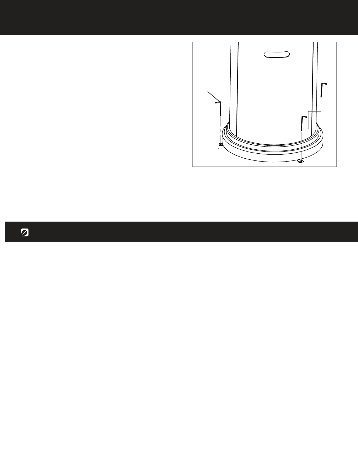
10. Use the 4 anchoring nuts (GG) to attach the
heater in place to the ground.
GG
OPERATION
• The glass tube may break if it is wet while in use; never use the heater while it’s raining outside.
• Do not splash any liquid on the heater while it is in use.
• Keep children away from the unit while in use; the glass tube may be extremely hot while in use.
Do not touch.
• Ensure that the heater is on a strong and at surface. The heater may be damaged if the unit tips
over.
• Never use the heater if the glass tube shows any cracks.
Before performing a leak test, be sure that no sparks can occur and you are in a spacious outdoor
area. Connect the propane gas tank to the regulator and turn the valve on the unit to the “off”
position. Brush a soap and water mixture on all connections. Turn the gas supply on; if bubbles
occur on any connection there may be a leak. If you smell gas or a leak is discovered turn the
gas valve off, disconnect propane gas tank and do not use the appliance until the leak is is
repaired.
Bond Manufacturing Company | Page 10
OPERATION
To Light
To Extinguish
1. Unscrew the ignition button on the burner to see if the battery (K) has already been placed inside.
If the battery (K) is not already within the ignition button on the burner, please place the battery
(K) into the ignition button slot.
2. Make sure the ignition control knob is turned to the “off” position. Connect propane gas tank and
slowly open the valve on the propane gas tank by turning the knob counterclockwise.
3. Press in and turn the ignition control knob to the “pilot” position; hold down for 1 minute.
4. Push the ignition button, while still holding down control knob down, to generate a spark.
5. Check to see if there is a pilot light through the glass tube (H). If there is, turn the control knob to
the “low” position.
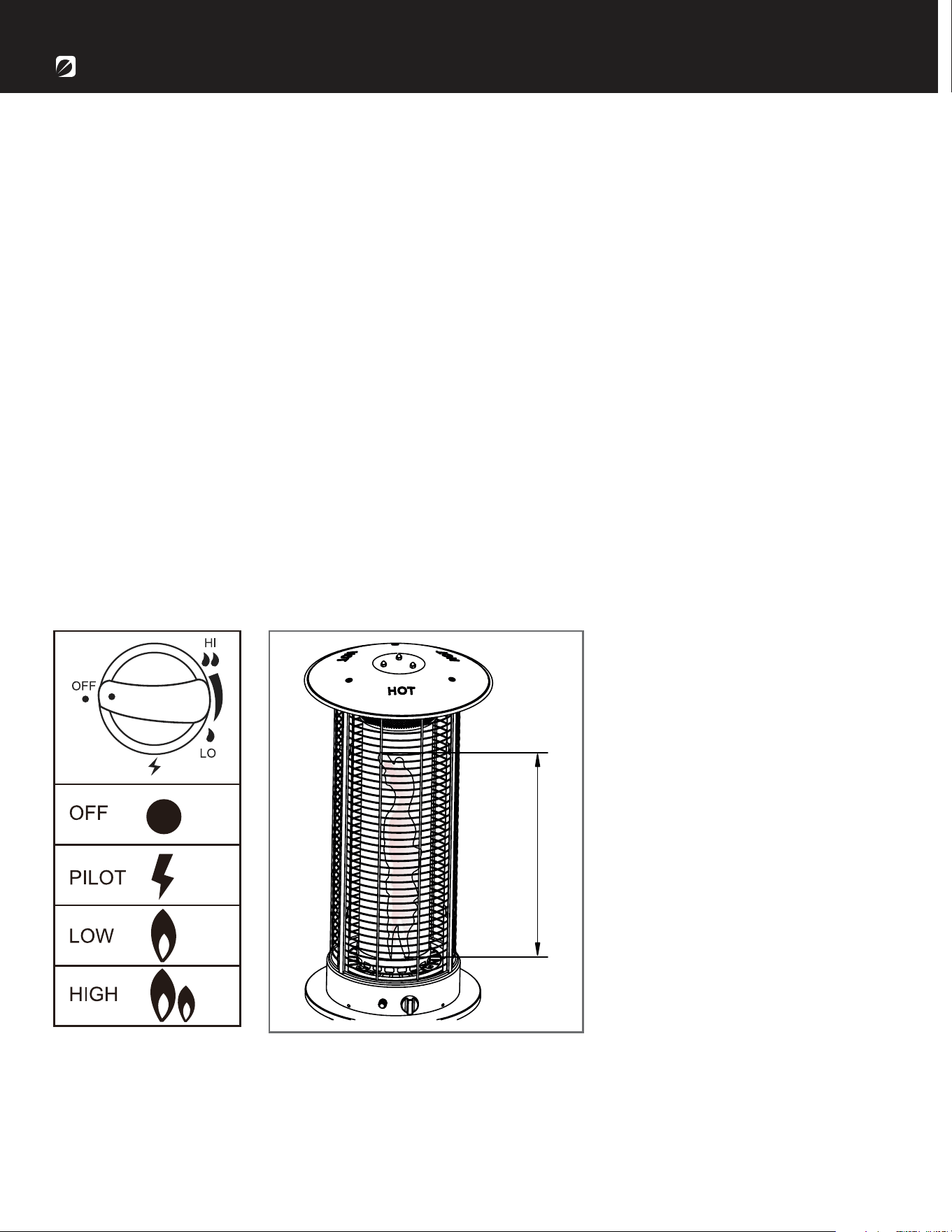
6. For maximum ame height and heat output, turn the control knob to the “high” position.
1. Push and turn the ignition control knob clockwise to the “off” position.
2. Turn the propane gas tank valve on the gas tank to close the gas supply and disconnect the
propane gas tank
WARNING: If the lighting instructions are not followed directly a re or explosion may occur resulting
in property damage, personal injury or death.
Observe ame height when lit. The
ame should be a yellow/blue color
between 20 - 28 inches in height.
1-866-771-2663 | Page 11
• Before performing any maintenance always disconnect propane gas tank.
• Keep the heating item free and clear from combustible materials.
• Visually inspect burner for obstructions and keep tank enclosure free and clear from debris.
• Use a soft brush to get rid of the mild stains, loose dirt and soil after the burner is completely
cooled down. Wipe down with a soft cloth.
• Harsh weather conditions may cause stubborn stains, discoloration and possibly rust pitting.
• Permanent damage may occur if powder or solvent comes in contact with painted or plastic
components on this heating unit.
• Keep the heating unit stored away from direct sunlight.
• If storing this unit inside, disconnect the propane gas tank from the gas valve.
• Not using manufacturer approved or supplied parts/accessories may result in a defective condition
and void the warranty of this heating unit.
• Carbon deposits may pose as a re hazard; clean the reector and inside of the glass tube with
soap and water if any carbon deposits are present.
MAINTENANCE
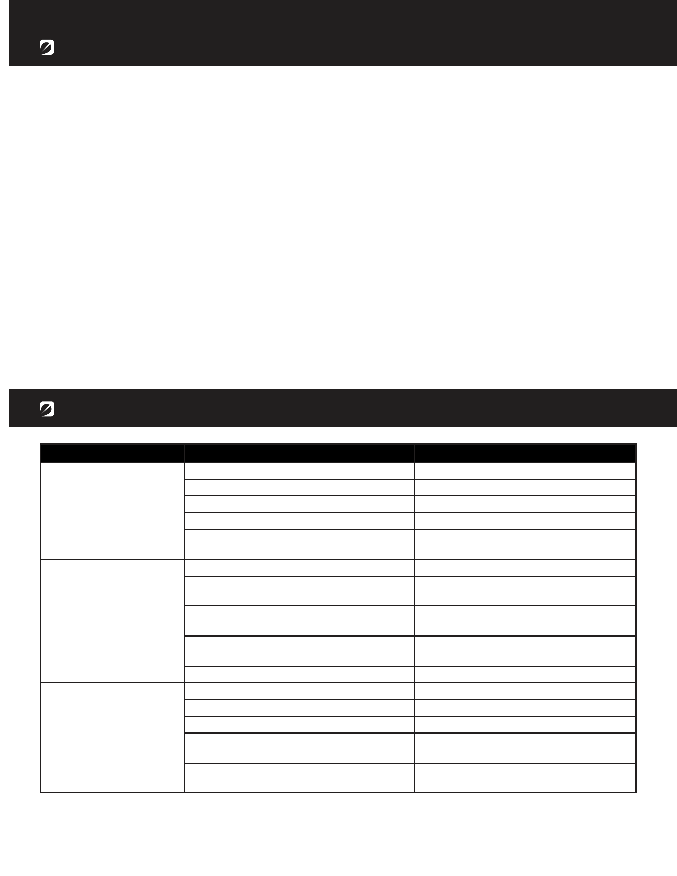
Problem Cause Solution
Gas valve may be off Turn the gas valve on
Gas tank may be empty Refill the gas tank
Orifice may be blocked Clean out the orifice
Air is within supply system Pump out air from all lines
Loose connection Check all fittings and tighten connections
as necessary
Debris around the pilot Clean out the debris
Loose connection Check all fittings and tighten connections
as necessary
Thermocouple is bad Call for a replacement part and replace
the thermocouple
Gas leak within the line Check all connections; call for a
replacement part if anything is damaged
Lack of gas pressure Gas tank is almost empty
Gas pressure is low Gas tank is almost empty
Orifice may be blocked Clean out the orifice
Control knob isn’t on Turn the control knob on
Thermocouple is bad Call for a replacement part and replace
the thermocouple
Pilot light assembly is bent or not in the
correct location
Place pilot light in the correct location
and retry lighting procedure
Pilot won’t light
Pilot won’t stay on
Burner won’t light
TROUBLESHOOTING
Bond Manufacturing Company | Page 12
WARRANTY
If you have any questions or concerns, please contact Bond Manufacturing Company at the below
resources:
CONTACT
Toll Free Phone 1-866-771-BOND (2663) | Monday - Friday, 8am - 4:30pm PST
Email customer[email protected]
Online www.bondmfg.com
The manufacturer warranty will be voided by, and manufacturer disclaims any responsibility for, the
following actions:
• Modication of the unit and/or components including the gas valve assembly.
• Use of any component part not manufactured or approved by Bond Manufacturing.
• Use and installation other than what is listed in this manual.
Please contact the manufacturer for replacement parts.