THANK YOU
Visual instruction of how to install this fan:
Visit www.homedepot.com and enter either the Item or Model number to nd
this fan and click the link of visual instruction in the product overview section.
USE AND CARE GUIDE
1-855-HD-HAMPTON
HAMPTONBAY.COM
Questions, problems, missing parts? Before returning to the store,
8 a.m. - 7 p.m., EST, Monday-Friday, 9 a.m. - 6 p.m., EST Saturday
call Hampton Bay Customer Service
We appreciate the trust and condence you have placed in Hampton Bay through the purchase of this ceiling fan. We strive to
continually create quality products designed to enhance your home. Visit us online to see our full line of products available for
your home improvement needs. Thank you for choosing Hampton Bay!
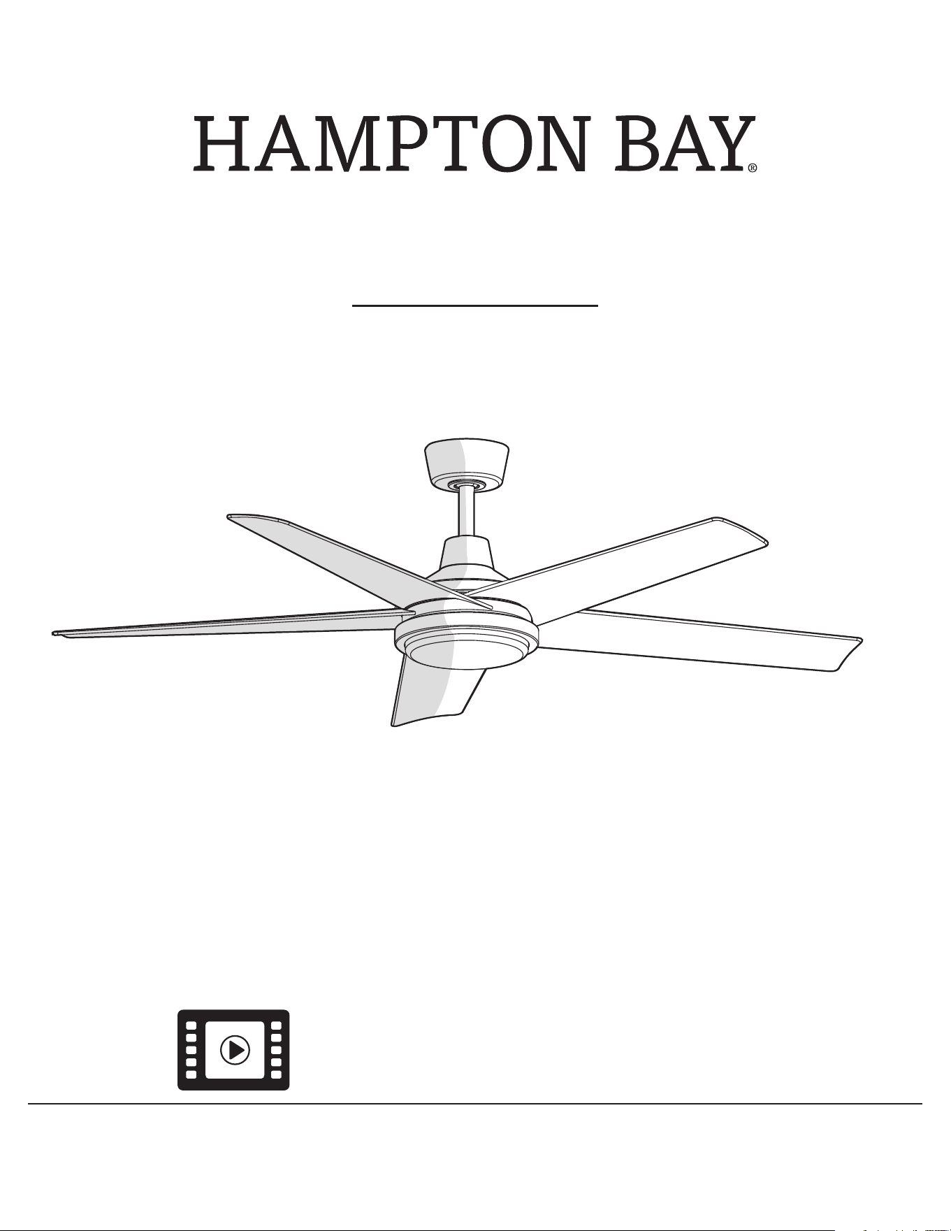
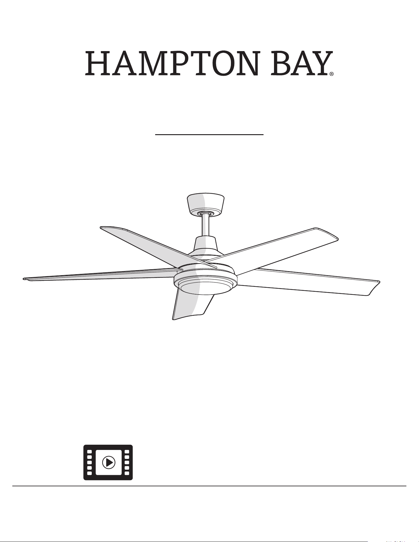
60 IN. LADSHAW
INDOOR/OUTDOOR CEILING FAN
Item #1010822868
1010822871
1010822869
Model #N3329-BN
N3329-MBK
N3329-MWH
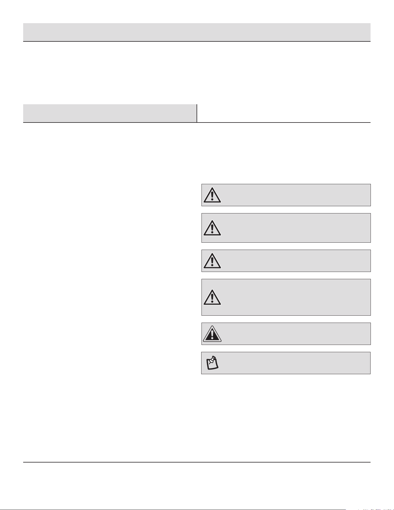
Table of Contents ..................................
Safety Information .................................
Warranty .........................................
Pre-installation ....................................
Installation .......................................
Assembly ........................................
Operation ........................................
Care and Cleaning .................................
Troubleshooting ...................................
2
Table of Contents
2
2
3
3
6
8
15
18
19
READ AND SAVE THESE INSTRUCTIONS
Safety Information
To reduce the risk of electric shock, ensure electricity has been
turned off at the circuit breaker or fuse box before beginning.
All wiring must be in accordance with the National Electrical
Code “ANSI/NFPA 70” and local electrical codes. Electrical
installation should be performed by a qualied licensed
electrician.
The outlet box and support structure must be securely mounted
and capable of reliably supporting a minimum of 35 lb (15.9 kg)
or less. Use only UL Listed outlet boxes marked “FOR FAN
SUPPORT.”
The fan must be mounted with a minimum of 7 ft (2.1 m)
clearance from the trailing edge of the blades to the oor.
Avoid placing objects in the path of the blades.
To avoid personal injury or damage to the fan and other items,
be cautious when working around or cleaning the fan.
Do not use water or detergents when cleaning the fan or fan
blades. A dry dust cloth or lightly dampened cloth will be
suitable for most cleaning.
After making electrical connections, spliced conductors should
be turned upward and pushed carefully up into the outlet box.
The wires should be spread apart with the grounded conductor
and the equipment-grounding conductor on one side of the
outlet box and ungrounded conductor on the other side of the
outlet box.
All set screws must be checked and retightened where
necessary before installation.
Suitable for use with solid-state speed control (RH797NRZB300
only).
1.
2.
3.
4.
5.
6.
7.
8.
9.
10.
The following responsible party designated in FCC §2.909 is
responsible for this declaration:
Model Number: N3329-BN, N3329-MBK, N3329-MWH
Company Name: TAL INTERNATIONAL CORPORATION
Company Address: 2919 E. Philadelphia St., Ontario, CA 91761, U.S.A.
Telephone Number: (909) 923-2888 Fax: (909) 923-8337
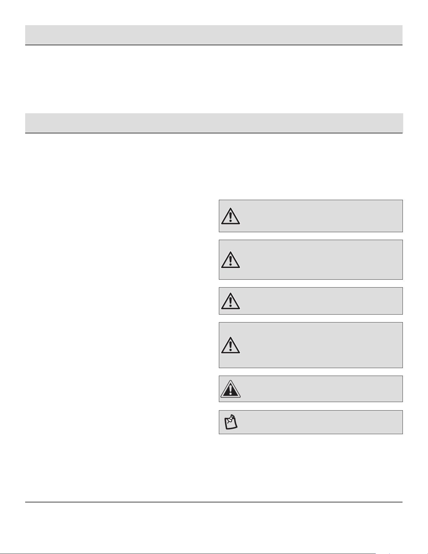
WARNING: To reduce the risk of personal injury, do not bend
the blade arms (also referred to as anges), when installing
the brackets, balancing the blades or cleaning the fan.
WARNING: Do not insert foreign objects between rotating
fan blades.
WARNING: To reduce the risk of re, electric shock or
personal injury, mount the fan to an outlet box marked
acceptable for fan support with the screws provided with the
outlet box.
CAUTION: To reduce the risk of personal injury, use only
the screws provided with the outlet box.
WARNING: To reduce the risk of electric shock, this fan
must be installed with an isolating wall control/switch.
NOTE: Suitable for use in wet locations.
Pre-Installation
SPECIFICATIONS
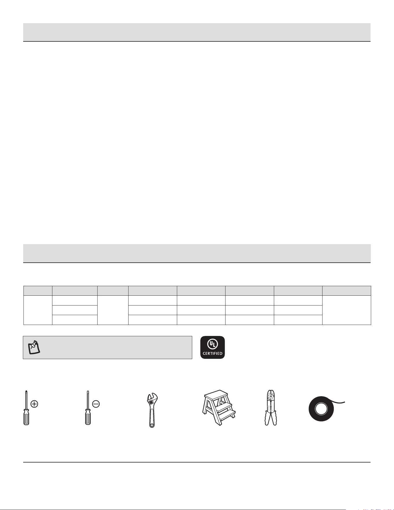
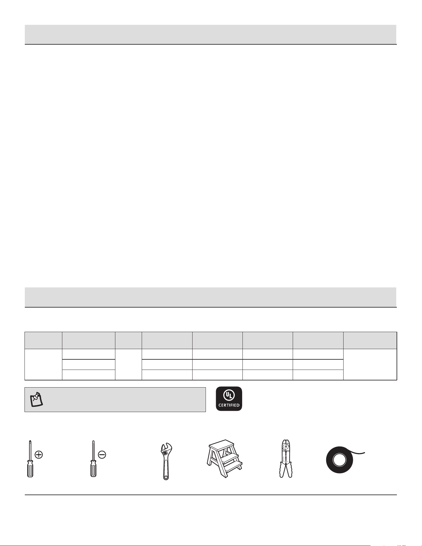
TOOLS REQUIRED
Warranty
Phillips
screwdriver
Flat blade
screwdriver
Step
ladder
Wire
stripper
Electrical
tape
Adjustable
wrench
NOTE: These are approximate measures. They do not
include amps and wattage used by the light kit.
3
60 in.
Low
(Speed 1)
Medium (Speed 4)
High (Speed 6)
120
Fan size Watts RPM CFMSpeed Volts Amps N.W.
0.07
0.32
0.65
4.74
19.50
45.40
49
121
169
2373
6346
8986
9.7 kg
(21.34 lb)
The manufacturer warrants the fan motor to be free from defects in workmanship and material present at time of shipment from the
factory for a period of lifetime after the date of purchase by the original purchaser. The manufacturer warrants the light kit (excluding any
glass), to be free from defects in workmanship and material at the time of shipment from the factory for a period of three years after the
date of purchase by the original purchaser. The manufacturer also warrants that all other fan parts, excluding any glass or acrylic blades,
to be free from defects in workmanship and material at the time of shipment from the factory for a period of one year after the date of
purchase by the original purchaser. We agree to correct such defects without charge or at our option replace with a comparable or
superior model if the product is returned. To obtain warranty service, you must present a copy of the receipt as proof of purchase. All
costs of removing and reinstalling the product are your responsibility. Damage to any part such as by accident, misuse, improper
installation or by afxing any accessories, is not covered by this warranty. Because of varying climatic conditions this warranty does not
cover any changes in brass nish, including rusting, pitting, corroding, tarnishing or peeling. Brass nishes of this type give the longest
useful life when protected from varying weather conditions. A certain amount of “wobble” is normal and should not be considered a
defect. Servicing performed by unauthorized persons shall render the warranty invalid. There is no other express warranty. We hereby
disclaim any and all warranties, including but not limited to those of merchantability and tness for a particular purpose to the extent
permitted by law. The duration of any implied warranty which cannot be disclaimed is limited to the time period as specied in the
express warranty. Some states do not allow limitation on how long an implied warranty lasts, so the above limitation may not apply to
you. The retailer shall not be liable for incidental, consequential, or special damages arising out of or in connection with product use or
performance except as may otherwise be accorded by law. Some states do not allow the exclusion of incidental or consequential
damages, so the above exclusion or limitation may not apply to you. This warranty gives specic legal rights, and you may also have other
rights which vary from state to state. This warranty supersedes all prior warranties. Shipping costs for any return of product as part of a
claim on the warranty must be paid by the customer.
Contact the Customer Service Team at 1-855-HD-HAMPTON or visit www.hamptonbay.com.
HAMPTONBAY.COM
Please contact 1-855-HD-HAMPTON for further assistance.
4
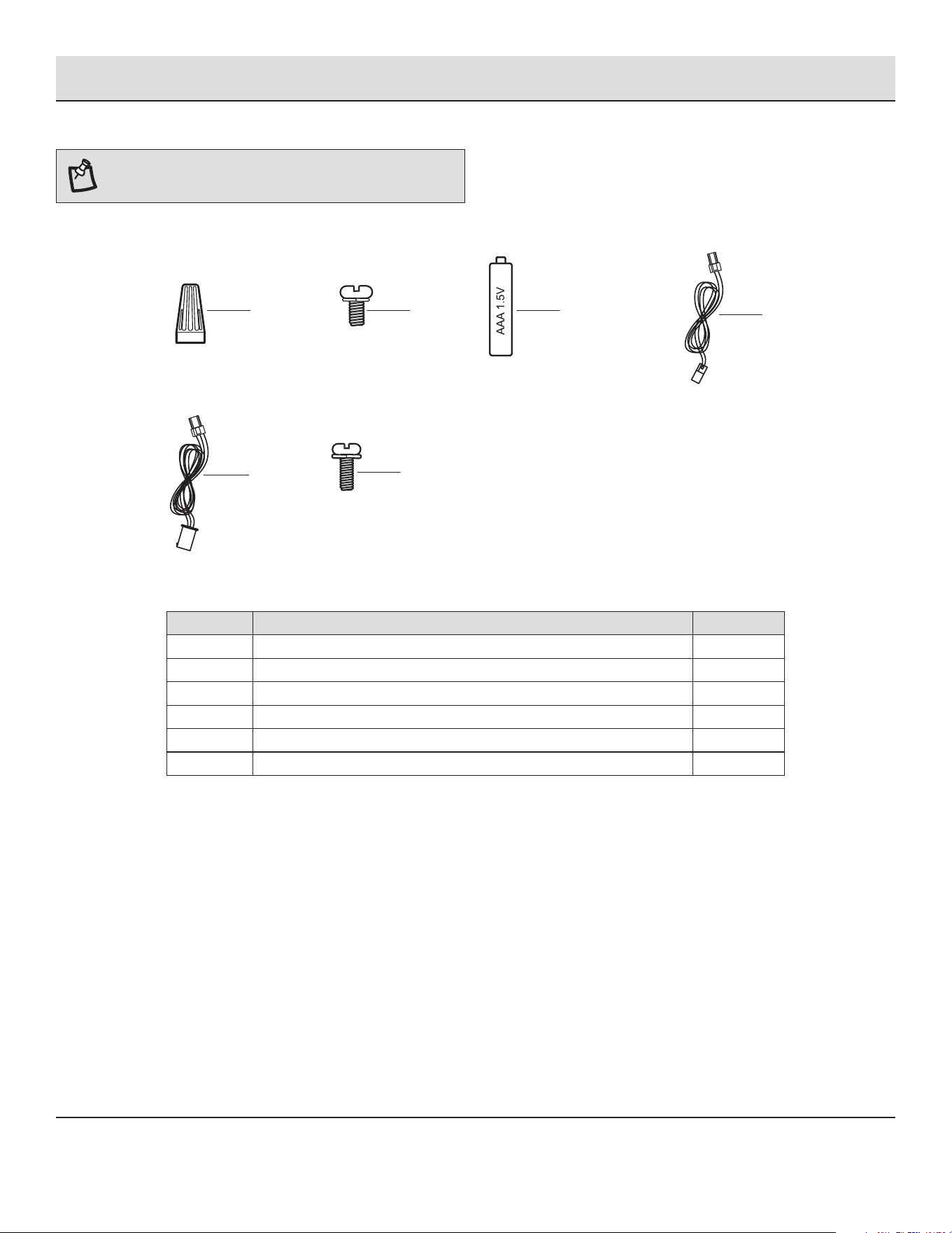
NOTE: Hardware not shown to actual size.
AA
BB
CC
DD
EE
FF
Plastic wire nut
Blade holder mounting screw with lock washer
1.5V AAA battery
2-pin extension cord
3-pin extension cord
Blade attachment screw with lock washer (additional)
Part Description
3
3
2
1
1
1
Quantity
HARDWARE INCLUDED
Pre-Installation (continued)
AA
EE
CCBB
DD
FF
5
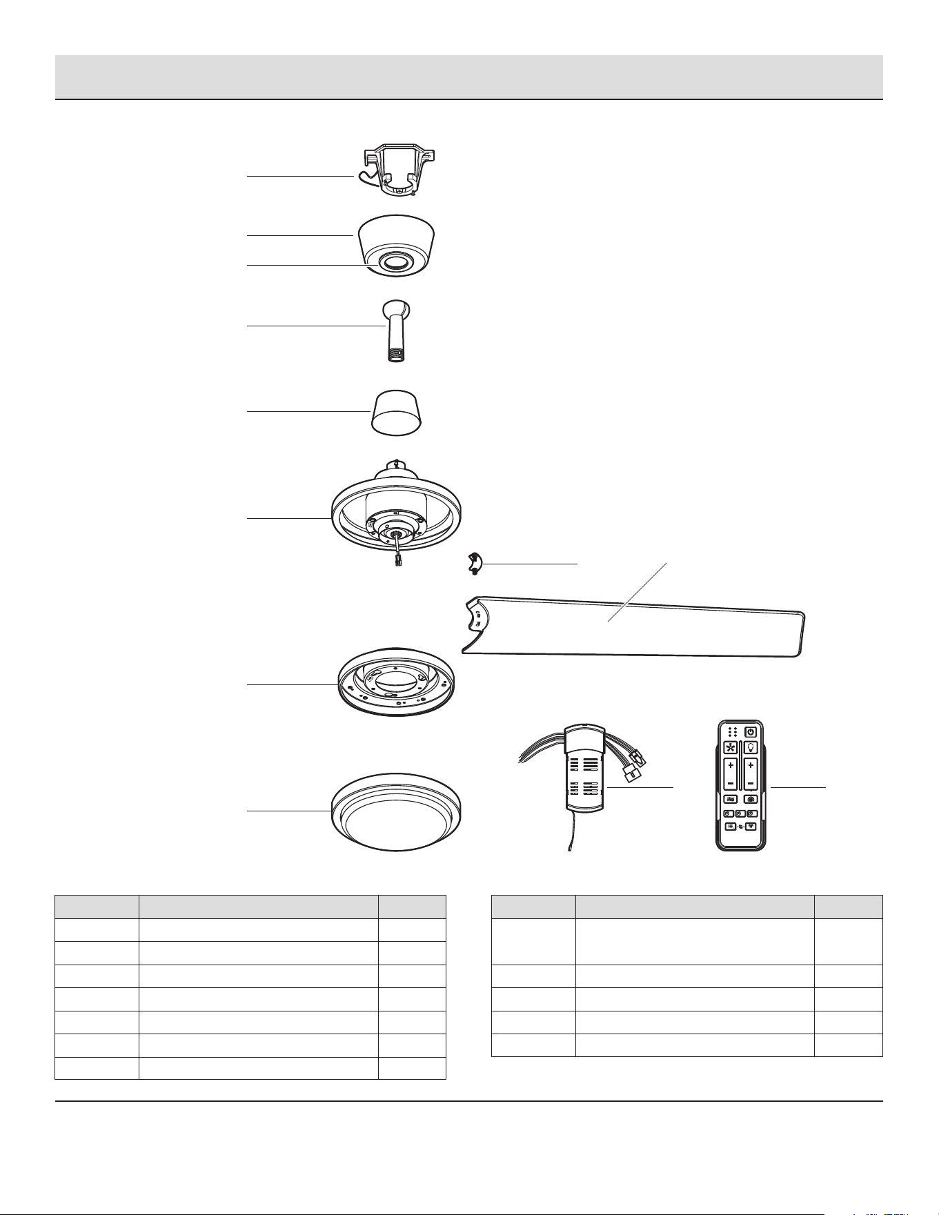
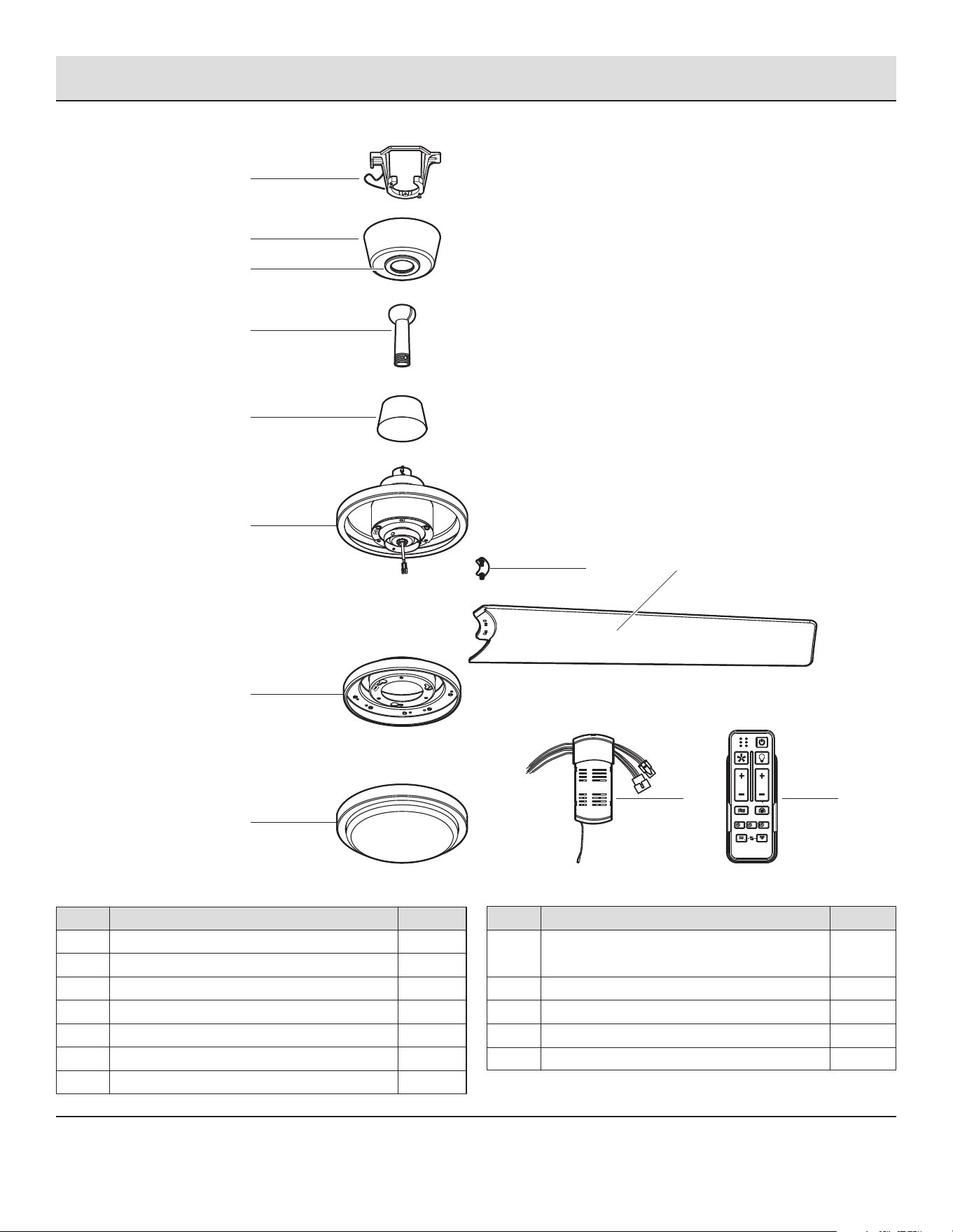
Part
I
J
K
L
Description
Blade support plate with screw and
lock washer
Blade
24 watt LED light kit assembly
Receiver
Remote control
Quantity
5
1
1
1
Part
A
B
C
D
E
F
G
Quantity
1
1
1
1
1
1
1
Description
Mounting bracket
Canopy
Canopy bottom cover (preassembled)
Hanger ball/downrod assembly
Coupling cover
Fan motor assembly
Blade holder
PACKAGE CONTENTS
Pre-Installation (continued)
K
G
L
J
A
D
E
F
B
C
HAMPTONBAY.COM
Please contact 1-855-HD-HAMPTON for further assistance.
TIMER
WINTER
SUMMER
FAN DIRECTION
HOLD 3 SEC.
2HR 8HR4HR
ON / OFF
ON / OFF
BREEZE
6 SPEED
BRIGHTNESS
COLOR TEMP.
ALL
I
H
5
H
6
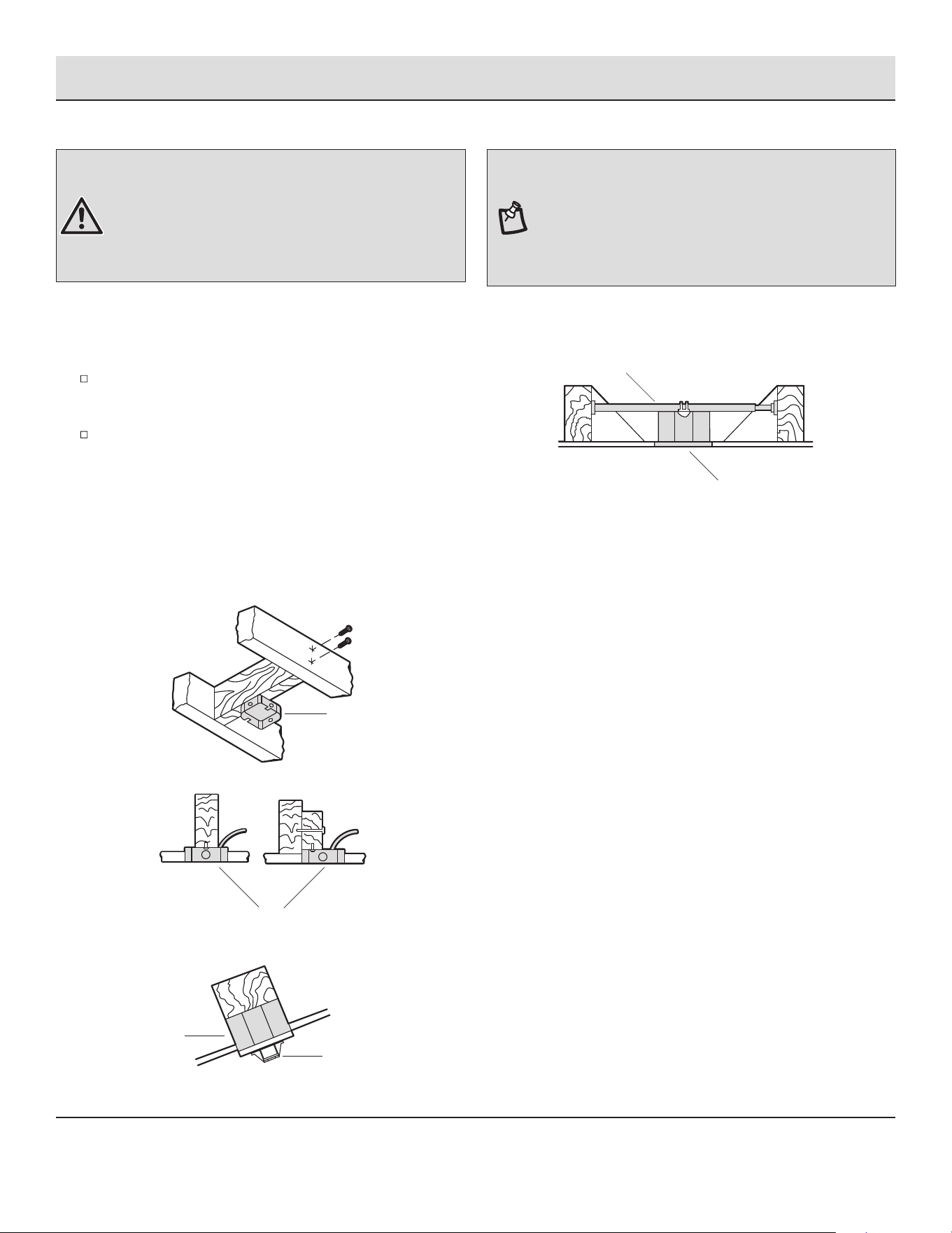
If your ceiling fan does not have an existing UL Listed mounting
box, then install one using the following instructions:
Disconnect the power by removing the fuses or turning off
the circuit breakers.
Secure the outlet box (not included) directly to the building
structure. Use appropriate fasteners and materials (not
included). The outlet box and its bracing must be able to fully
support the weight of the moving fan (at least 35 lb.). Do not
use a plastic outlet box.
The illustrations below show three different ways to mount the
outlet box (not included).
To hang your fan where there is an existing xture but no ceiling
joist, you may need an installation hanger bar (not included) as
shown above.
Outlet Box
Outlet Box
Hanger Bar
Outlet Box
Recessed
Outlet
Box
A
WARNING: To reduce the risk of re, electric shock, or
personal injury, mount the fan to an outlet box marked
acceptable for fan support using the screws provided with the
outlet box. An outlet box commonly used for the support of
lighting xtures may not be acceptable for fan support and
may need to be replaced. If in doubt, consult a qualied
electrician.
MOUNTING OPTIONS
Installation
NOTE: You may need a longer downrod to maintain proper
blade clearance when installing on a steep, sloped ceiling.
The maximum angle allowable is 18° away from horizontal. If
the canopy (B) touches the hanger ball/downrod assembly (D),
remove the decorative canopy bottom cover (C) and turn the
canopy (B) 180° before attaching the canopy (B) to the
mounting bracket (A).
7 HAMPTONBAY.COM
Please contact 1-855-HD-HAMPTON for further assistance.
1
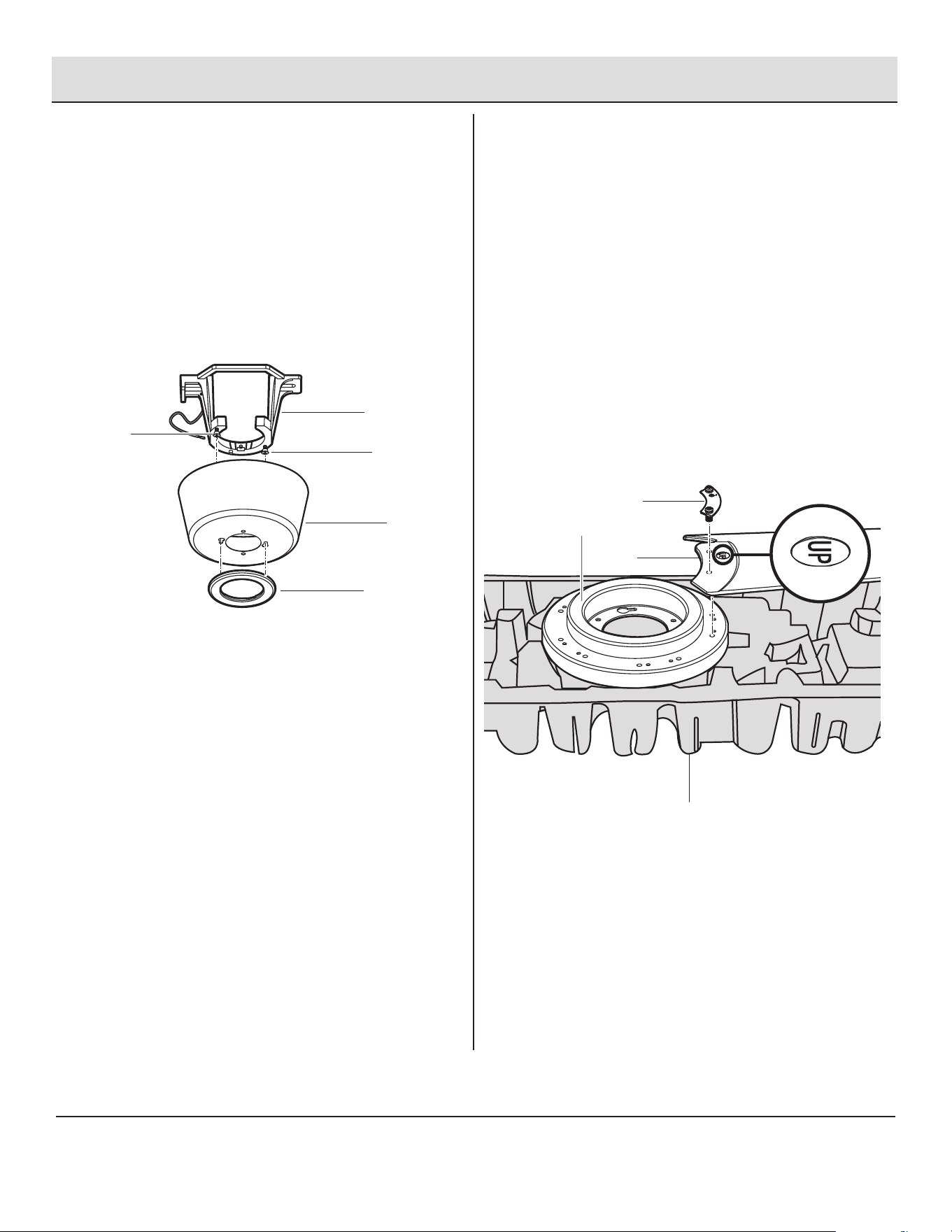
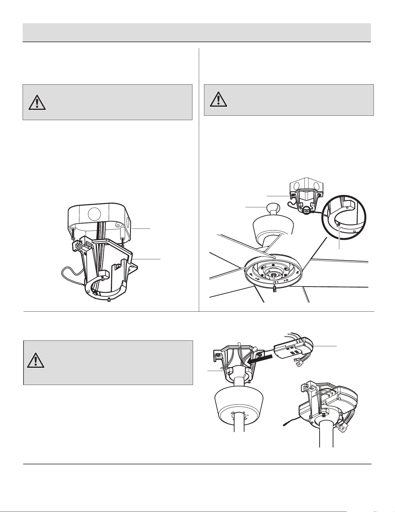
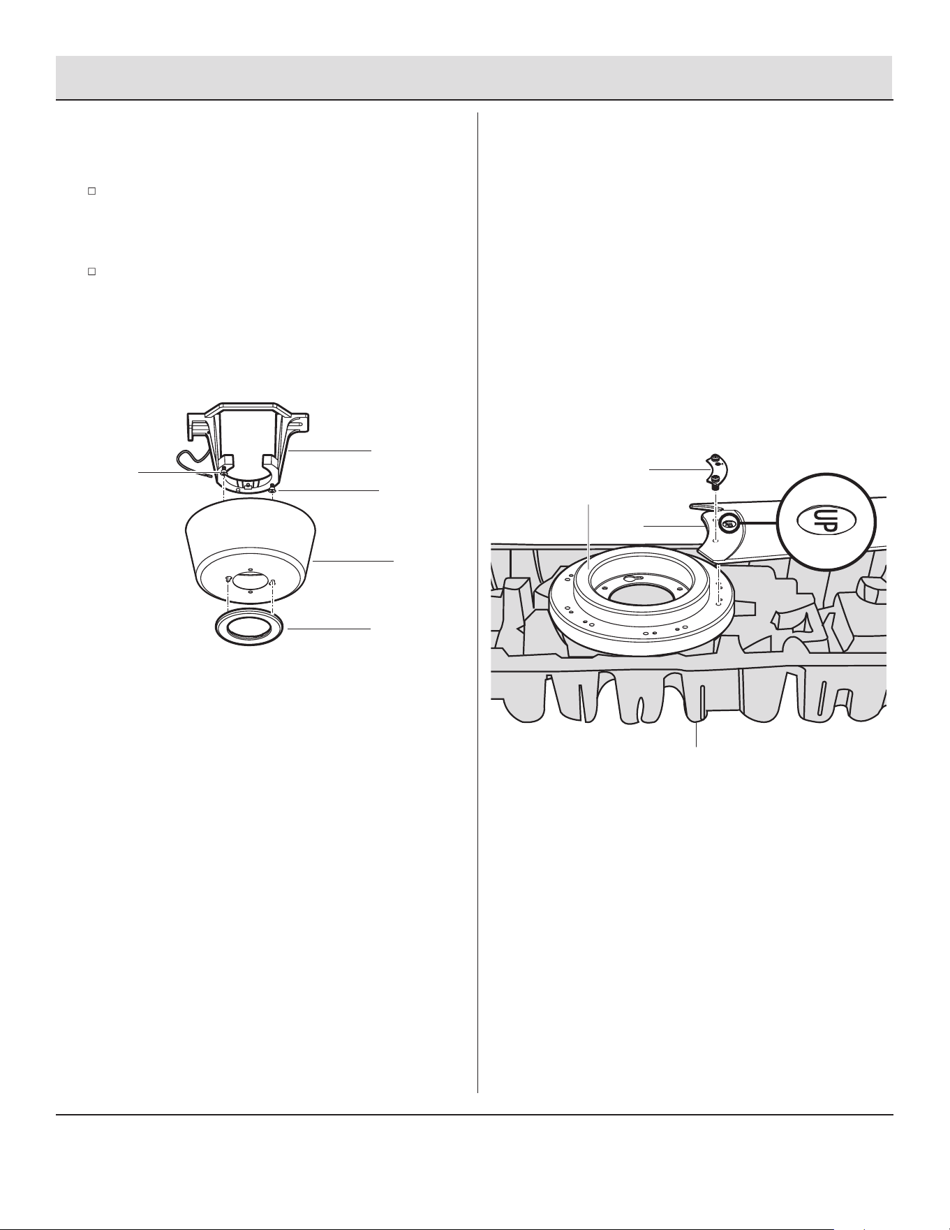
Assembly
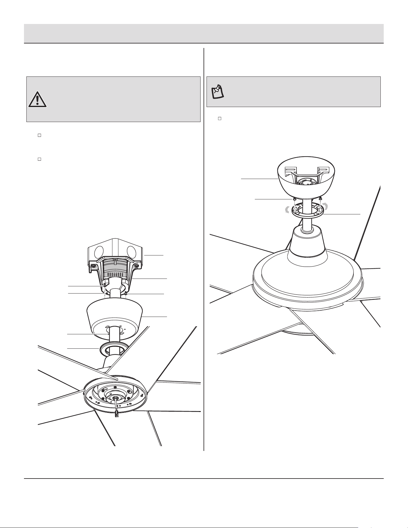
Preparing the canopy
□ Remove the canopy bottom cover (C) from the canopy (B)
by turning the canopy bottom cover (C) counterclockwise.
□ Remove the mounting bracket (A) from the canopy (B) by
loosening canopy mounting screws (GG) a half turn from
the screw head. Next, turn the canopy (B) counterclockwise
to remove the mounting bracket (A) from the canopy (B).
2
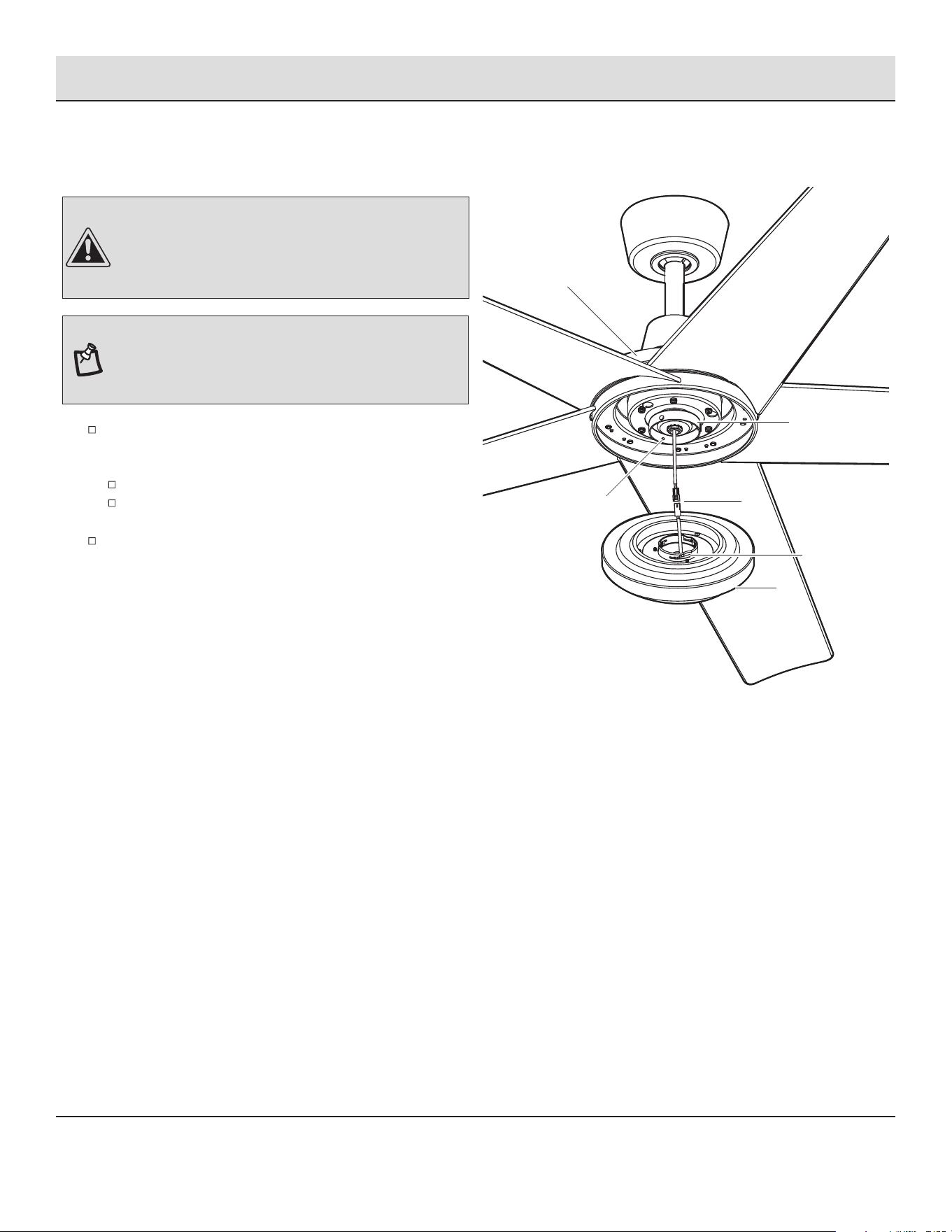
Attaching the fan blades
□ Begin by using the original product packaging to create a
base to hold the blade holder (G). Place the blade holder (G)
with the bottom facing up.
□ Bring a fan blade (I) to the blade holder (G) and ensure that
“UP” side is facing upward. Place the blade (I) onto the
blade holder (G) and align with those holes underneath.
□ Place a blade support plate (H) with screws over the holes
and tighten all screws securely. Repeat this procedure
with the remaining blades (I).
GG
A
GG
B
C
Pulp packaging
H
I
G
8
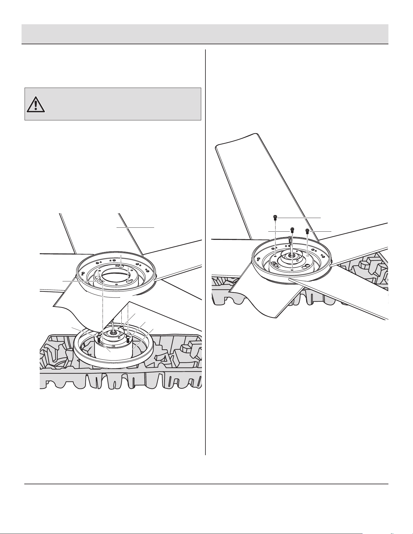
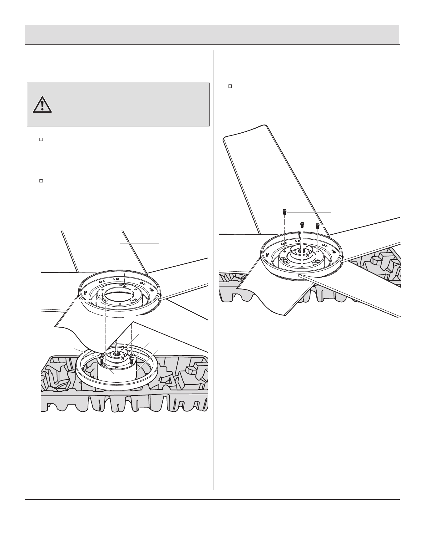
3a
Assembly (continued)
Fastening the blade assemblies to
the motor
3b
Fastening the blade assemblies to
the motor
WARNING: To reduce the risk of personal injury, do not bend
the blade (I) while installing, balancing the blades (I), or
cleaning the fan. Do not insert foreign objects between rotating
fan blades (I).
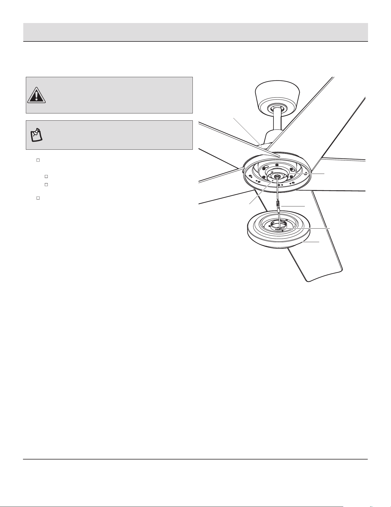
□ Place the fan motor (F) with the bottom facing up by using
the original product packaging, and loose three screws
(HH) on the fan motor. (Do not remove)
□ Line up the arrow label on the blade holder and that on the
fan motor. Place keyholes on the blade holder over three
screws (HH) on the fan motor, and slide until three screws
(HH) lock in place at the narrow section. Tighten all three
screws.
□ Install three blade holder screws with lock washers (BB) in
three screws holes on the blade holder and make sure they
are securely tightened.
F
HH
HH
Arrow
HH
Arrow
BB
BB
BB
I
9 HAMPTONBAY.COM
Please contact 1-855-HD-HAMPTON for further assistance.
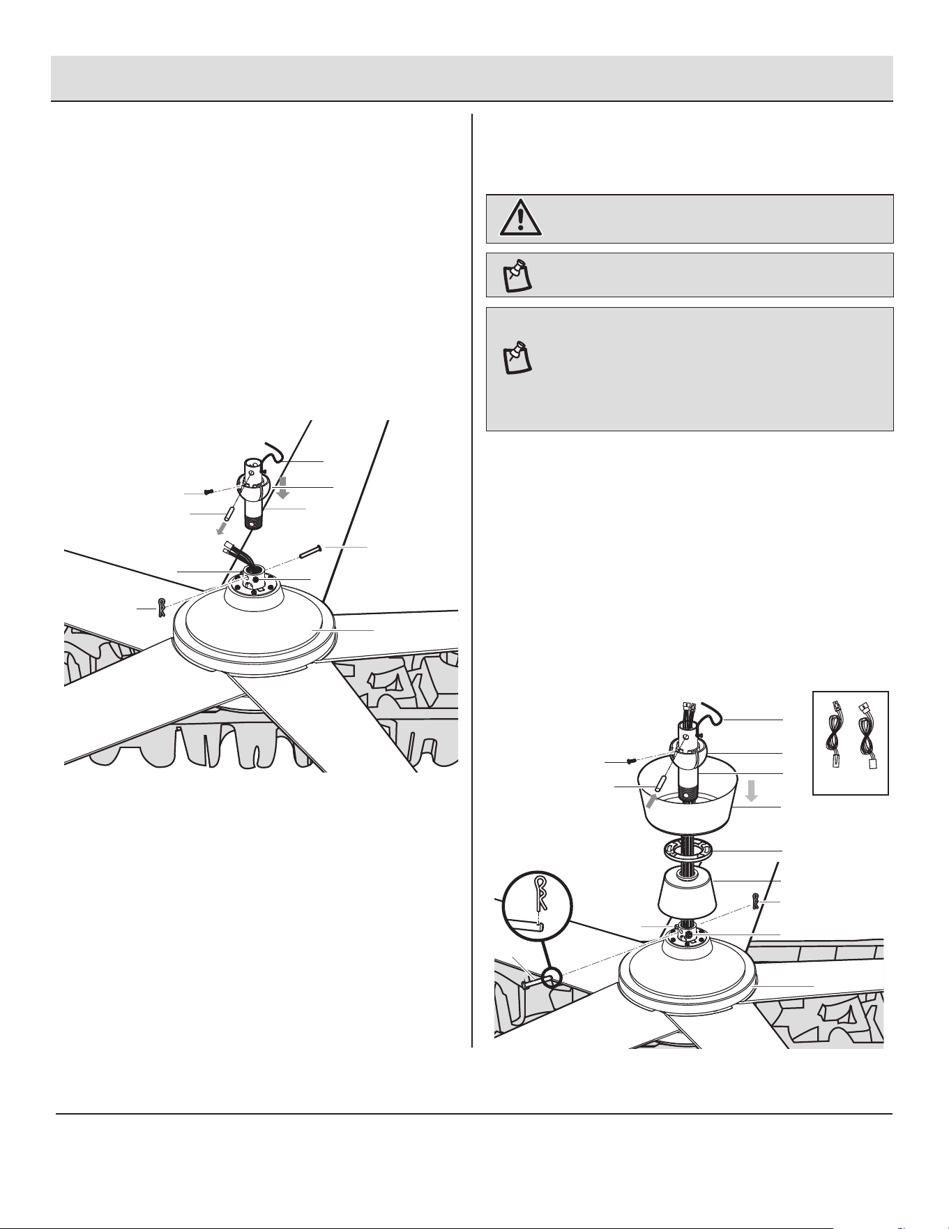
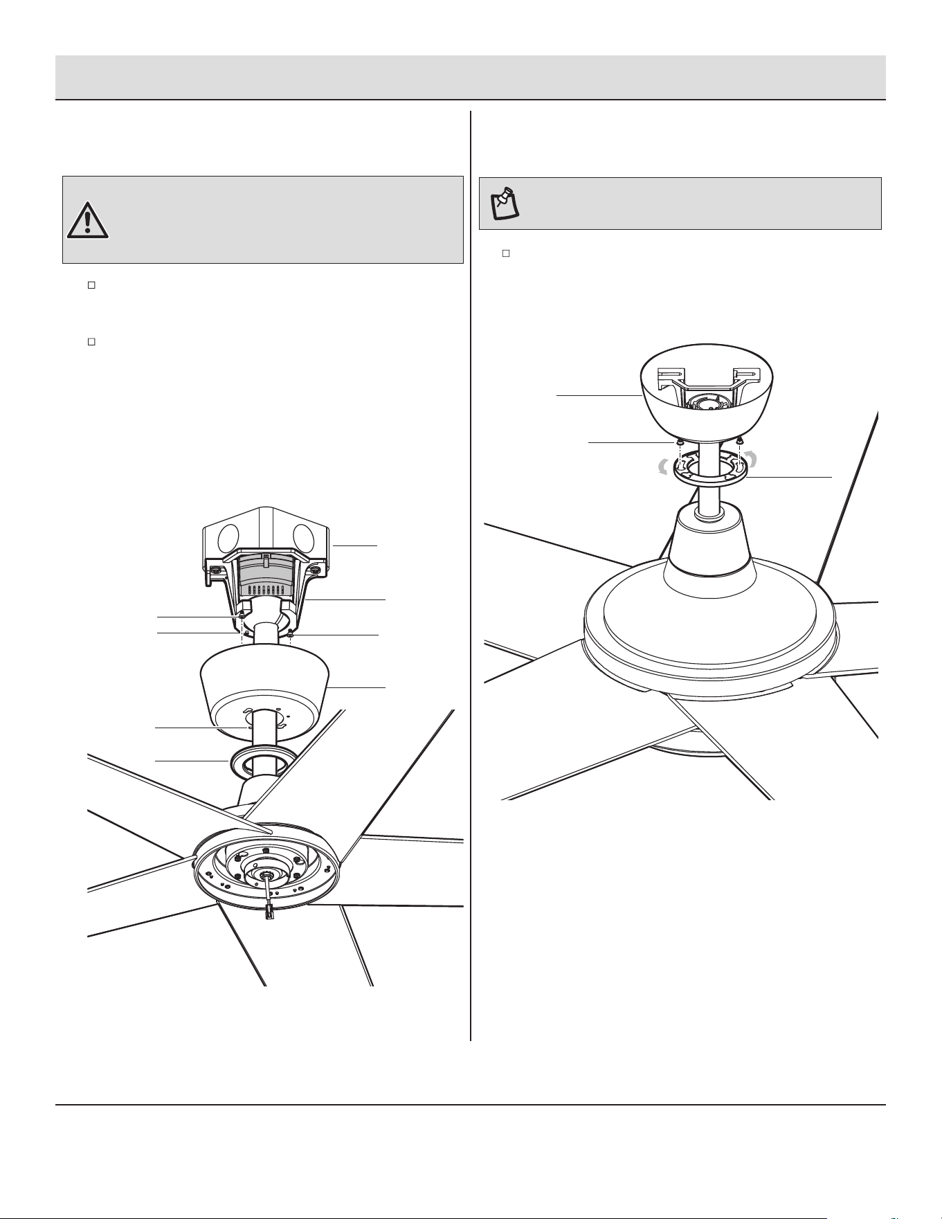
Assembly (continued)
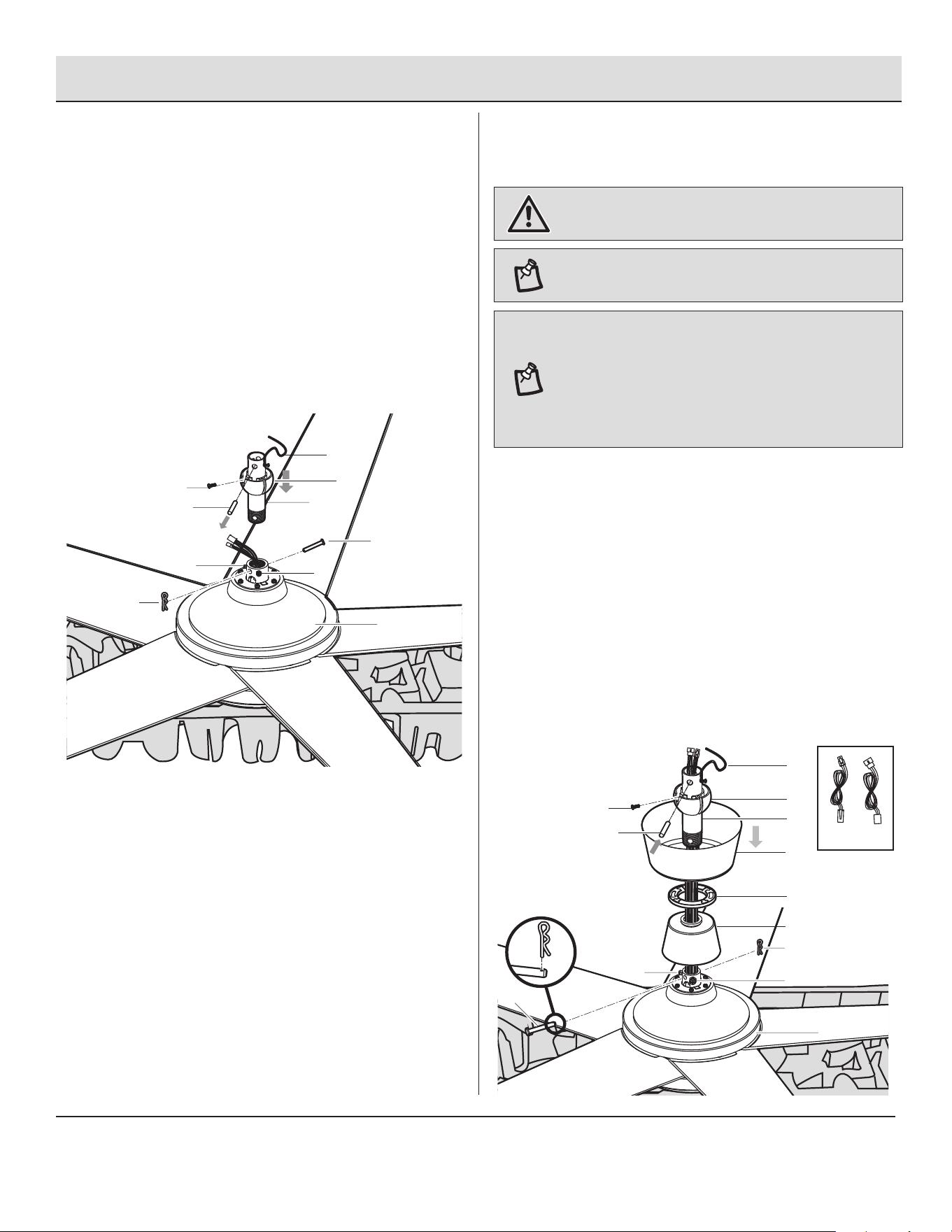
4
Preparing the motor
□ Flip the motor. Remove the cotter pin (II) and clevis pin
(JJ), and loosen the two collar set screws (KK) from the
motor collar.
□ Take out the set screw (LL) located in the hanger ball (MM),
lower the hanger ball (MM) and remove the cross pin (NN).
Remove the hanger ball (MM) from the hanger ball/downrod
assembly (D).
□ Remove the ground lead (OO) from the downrod assembly (D).
5
Assembling the fan
□ Carefully feed the motor wires up through the downrod
(PP). Thread the downrod (PP) into the collar.
□ Align the holes and replace the clevis pin (JJ) and cotter
pin (II). Tighten the two collar setscrews (KK).
□ Slip the coupling cover (E), the canopy bottom cover (C),
and the canopy (B) onto the downrod (PP).
□ Carefully reinstall the hanger ball (MM) and the ground lead
(OO) onto the downrod (PP). Being sure that the cross pin
(NN) is in the correct position, the set screw (LL) is tightened
and wires are not twisted.
WARNING: Failure to properly install the cotter pin (II) could
result in the fan loosening and possibly falling.
NOTE: If a longer downrod (not included) is needed, take out the
screw located in the hanger ball (MM), lower the hanger ball (MM)
and remove the pin (NN). Remove all three pieces from the
downrod and assemble them onto the new longer downrod before
proceeding to the downrod installation. Be sure to snap together
the 2-pin and 3-pin connectors, the two male plugs from the fan
and female plugs from the extension cords (DD and EE).
NOTE:
DO NOT install extensions cords (DDand EE) when
using included downrod.
KK
KK
F
II
C
E
B
LL
NN
MM
PP
OO
JJ
II
JJ
KK
KK
F
LL
D
NN
MM
OO
EE
DD
10
Assembly — Hanging the Fan
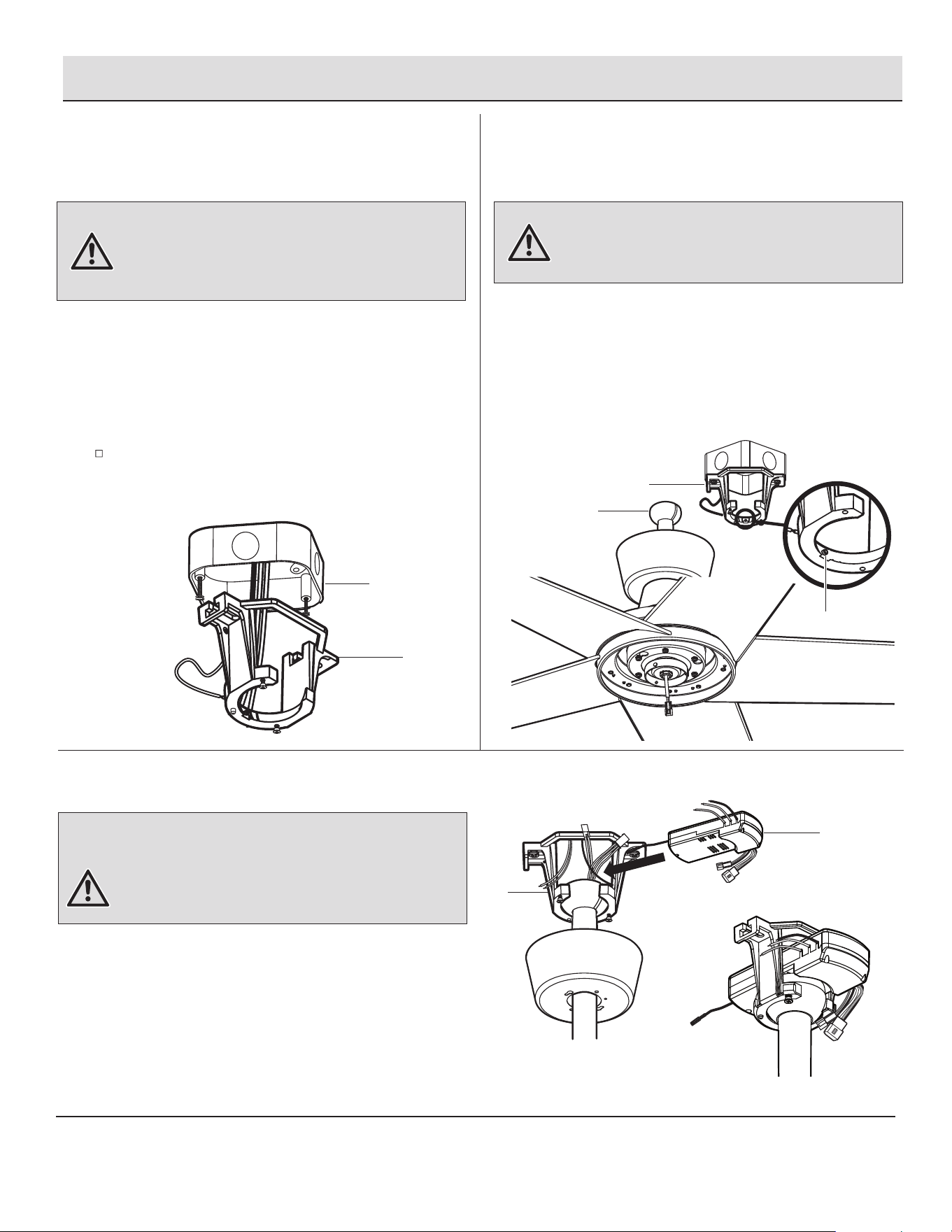
6
Installing the mounting bracket
to the electrical box
Hanging the fan to the mounting
bracket
□ Carefully lift the fan motor assembly (F) up to the
mounting bracket (A) and seat the hanger
ball/downrod assembly (D) in the mounting bracket
(A) socket. Make sure the tab on the mounting
bracket (A) socket is properly seated in the groove in
the hanger ball/downrod assembly (D). This will help
to balance the ceiling fan.
7
WARNING: To reduce the risk of re, electric shock or
other personal injury, mount the fan only to an outlet box or
supporting system marked acceptable for fan support and
use the mounting screws provided with the outlet box.
WARNING: The tab in the ring must rest in the groove of
the hanger ball/downrod assembly (D). Failure to properly
seat the tab in the groove could cause damage to the wiring.
□ Pass the 120-volt supply wires through the center
hole in the mounting bracket (A).
□ Attach the mounting bracket (A) on the outlet box by
sliding the mounting bracket (A) over the screws
provided with the outlet box. Note that the at side of
the mounting bracket (A) is toward the outlet box.
□ Securely tighten the two mounting screws.
D
F
8
Installing the receiver
□ Position the house supply black wire to one side of
the mounting bracket (A), and position the house
supply white and green wires to the opposite side.
□ Push the yellow antenna wire through the mounting
bracket (A) and insert the narrow end of the receiver
(K) (as shown, at side towards the ceiling) into the
slide-on mounting bracket (A) until it rests on top of
the ball/downrod assembly.
WARNING:
To reduce the risk of re or electric shock,
remember to disconnect power. The electrical wiring must meet
all local and national electrical code requirements. The electrical
source and fan must be 120 volt, 60Hz. Do not use this product in
conjunction with any variable wall control. Incorrect wire
connection can damage this receiver.
View after installation
A
K
A
Outlet Box
A
Tab
11 HAMPTONBAY.COM
Please contact 1-855-HD-HAMPTON for further assistance.
Assembly — Hanging the Fan (continued)
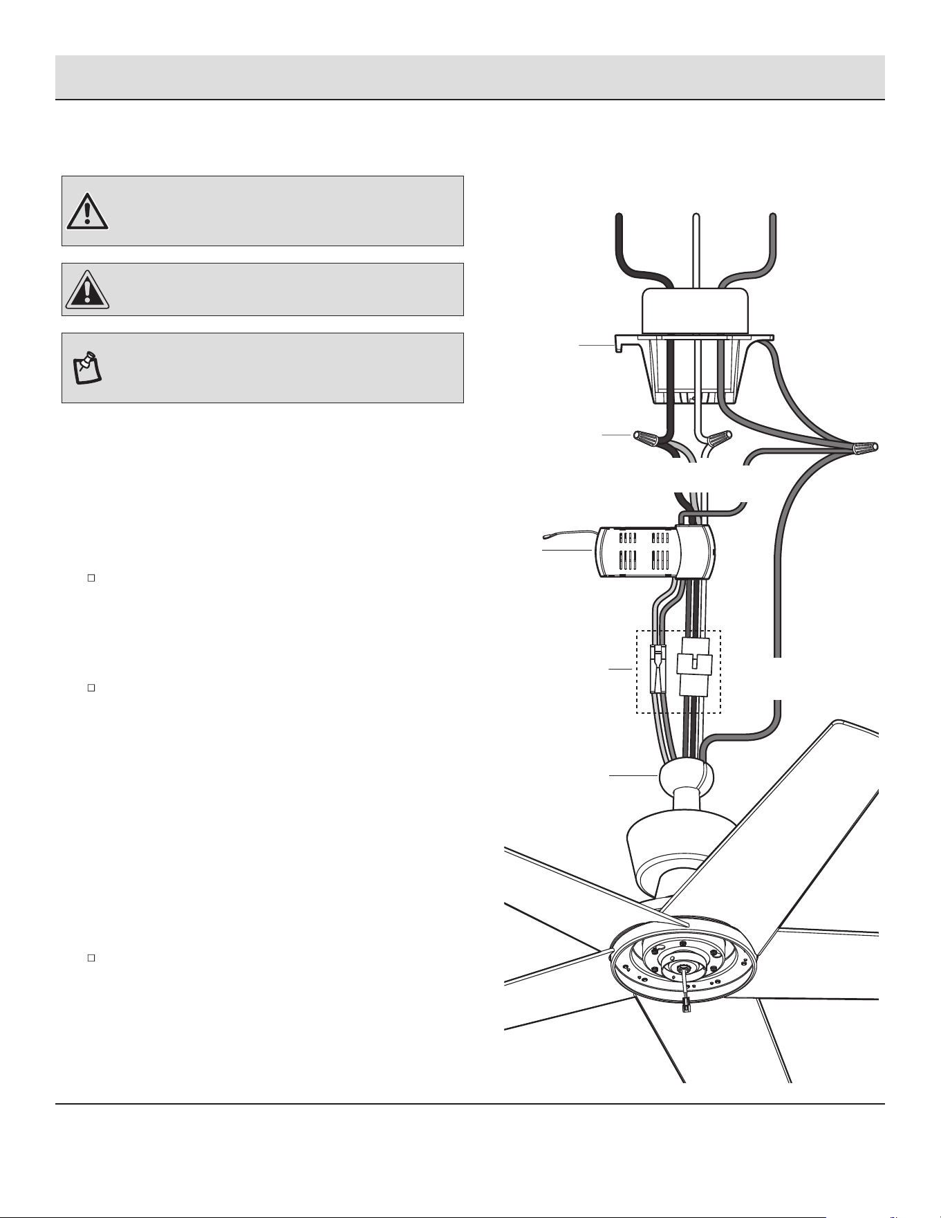
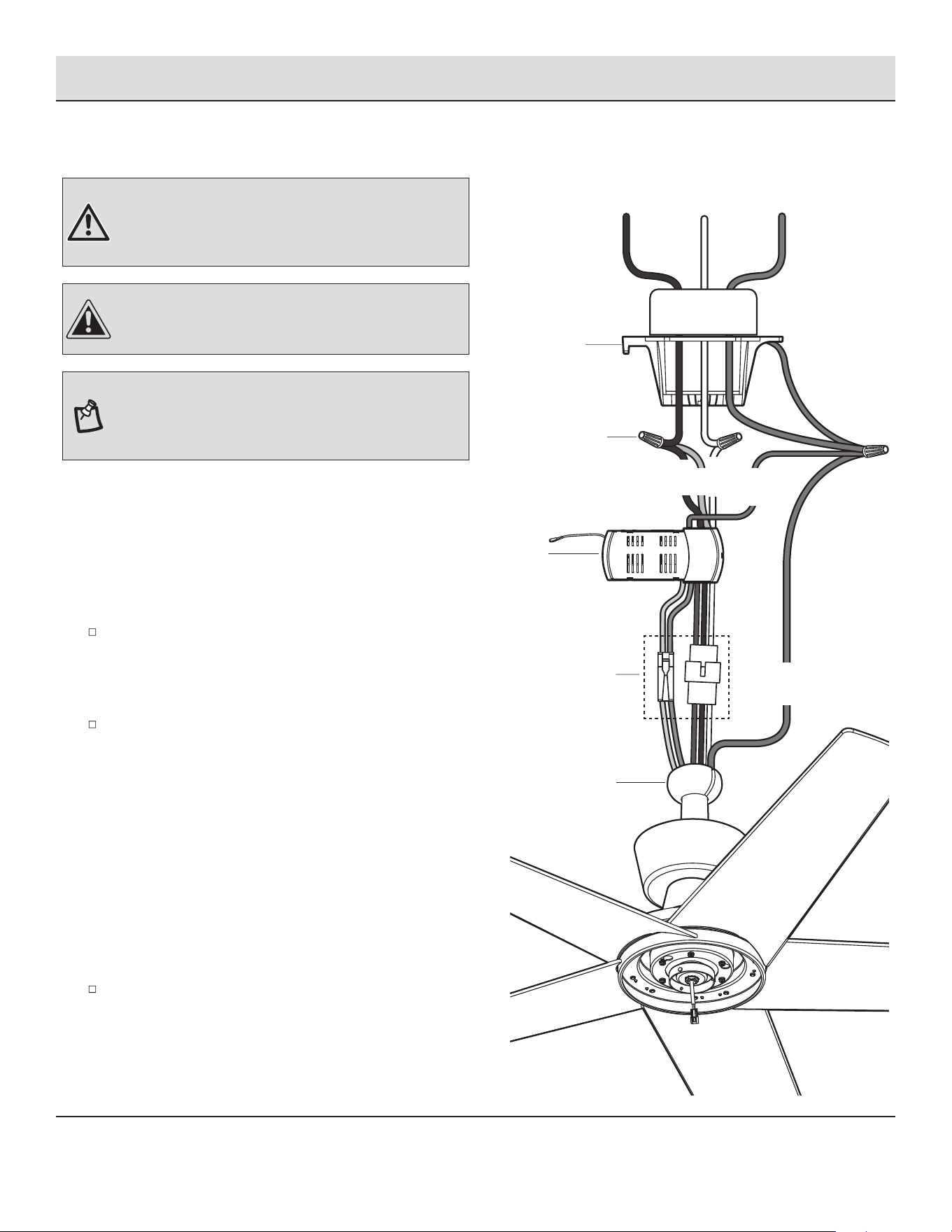
9a
Making the electrical connections
NOTE: The fan must be installed at a maximum distance of
20 ft. from the remote control for proper signal transmission
between the remote control and the fan's receiving unit.
WARNING: Check to see that all connections are tight,
including ground, and that no bare wire is visible at the wire
nuts (except for the ground wire).
If you feel you do not have enough electrical wiring knowledge
or experience, have your fan installed by a licensed electrician.
Follow the steps below to connect the fan to your household
wiring. Use the plastic wire nuts (AA) with your fan. Secure the
plastic wire nuts (AA) with electrical tape. Make sure there are
no loose strands or connections.
Make wire connections from the fan to the receiver (K).
From fan To receiver
2-pin connector--------------- 2-pin connector
3-pin connector--------------- 3-pin connector
Make wire connections from the receiver (K) and fan to the
outlet box as follows, using the wire nuts (AA).
From receiver To outlet box
Black "AC in L" +
Red wire "for Light" -------- Black wire (Hot)
White wire "AC in N" --------- White wire (Neutral)
From fan and receiver To outlet box
Green wires* ----------------- Green or bare wire (Ground)
* There are three green grounding leads: one from the mounting
bracket (A), one from the hanger ball/downrod assembly (D) and
one from the receiver (K).
Turn the wire nut connections upward, spreading them apart
so the green (ground) and white wires will be on one side of
the outlet box and the black wire will be on the other side.
Carefully tuck the connections up into the outlet box.
CAUTION: To reduce the risk of electric shock, this fan must
be installed with an isolating wall control/switch.
AA
2-pin and 3-pin
connectors
K
White
Green
Black
Black
Ground
White
conductor
Green
Outlet Box
D
A
Red
12
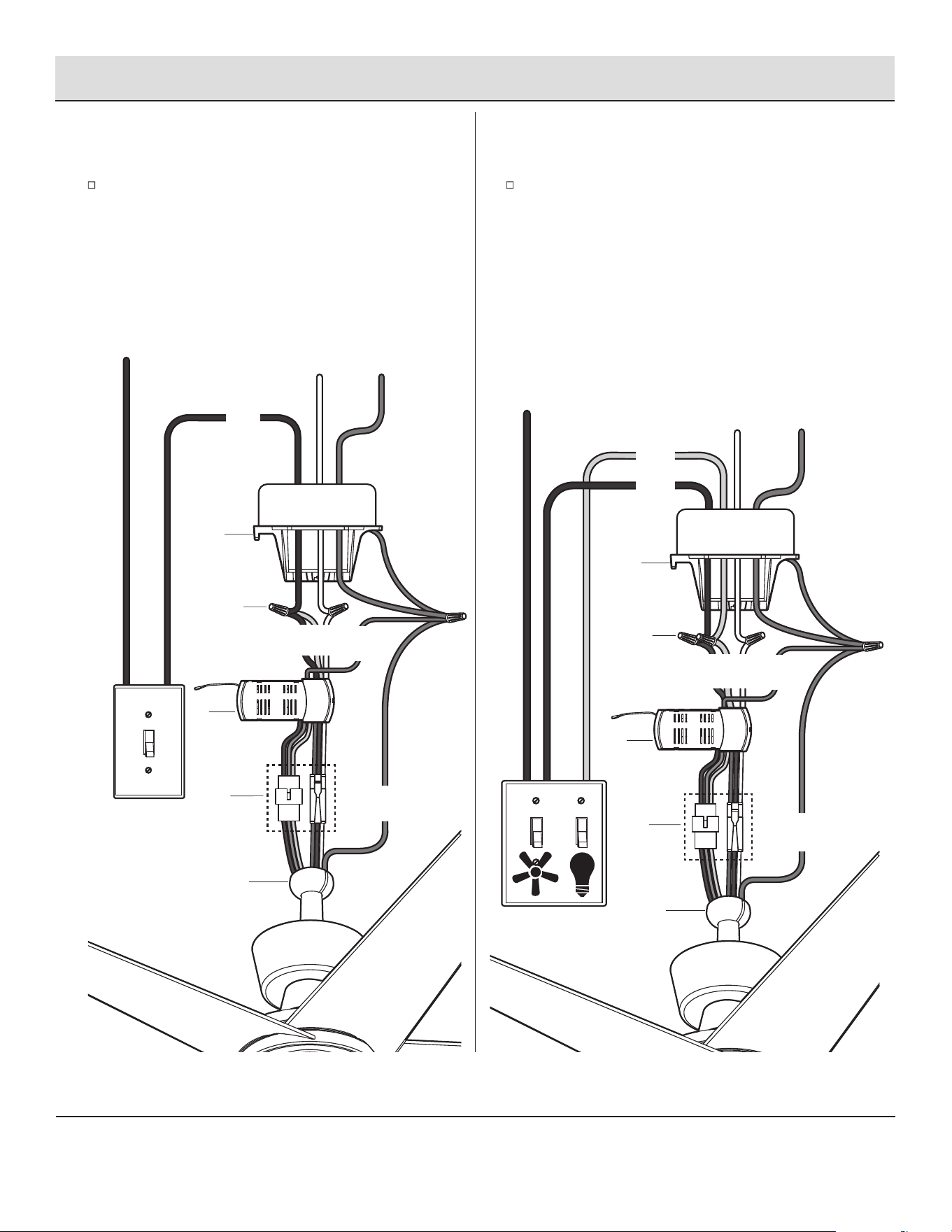
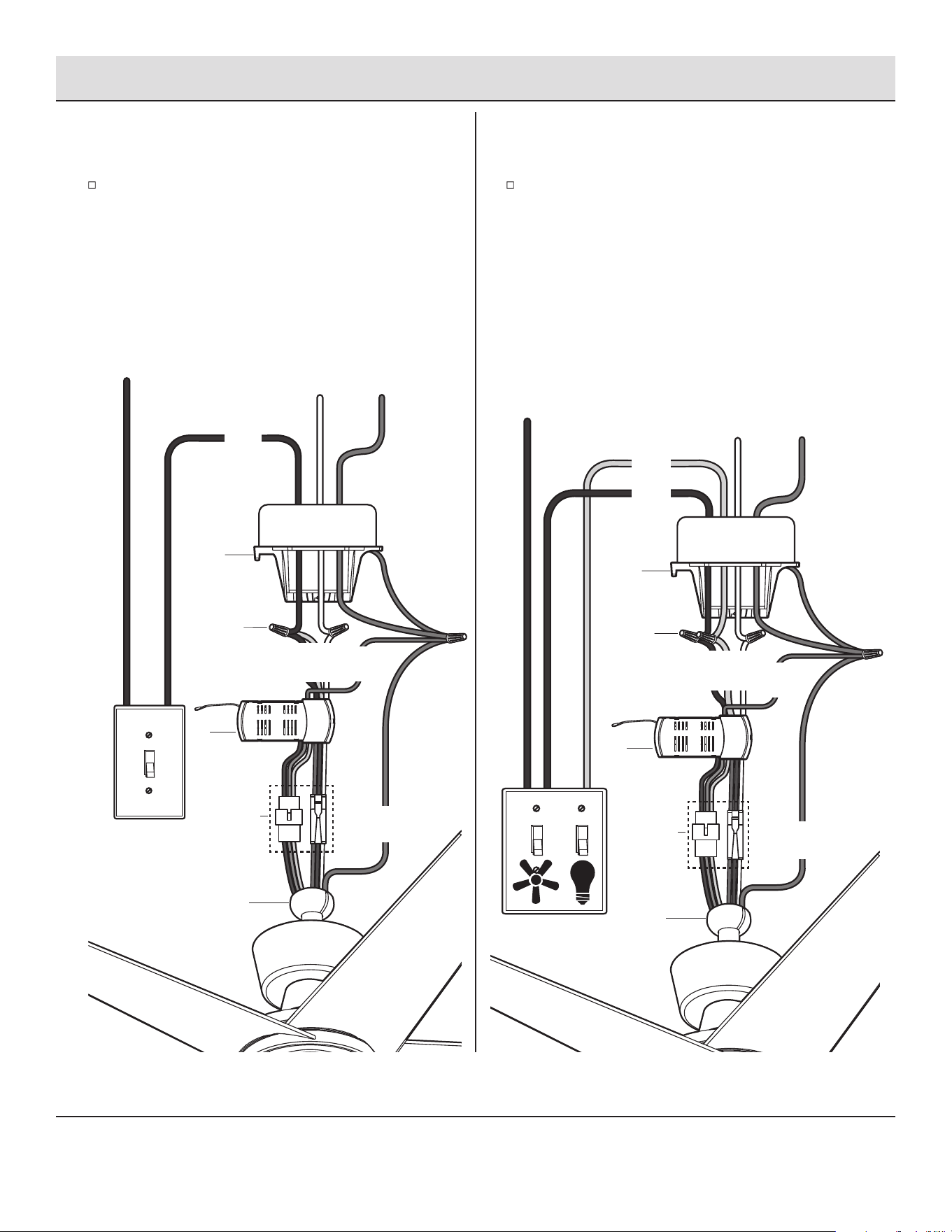
Assembly — Hanging the Fan (optional)
Single Switch Connections
9b
Dual Switch Connections
9c
On a single switch the fan and light can be turned on or off
together. Make wire connections as follows, using the wire
nuts (AA). Wall switch not included.
From Fan To Outlet Box
Black + Red Wires ---------- Black Wire (Hot)
White Wire ------------------- White Wire (Neutral)
Green Wires* ---------------- Green or Bare Wire (Ground)
On a dual switch the fan and light can be turned on or off
separately. Make wire connections as follows, using the
wire nuts (AA). Wall switch not included.
From Fan To Outlet Box
Black Wire (for Fan) --------- Black Wire (Hot #1)
Red Wire (for Light) ---------- Red Wire (Hot #2 but may
be in a color other than black,
white or green)
White Wire ------------------- White Wire (Neutral)
Green Wires* ---------------- Green or Bare Wire (Ground)
AC IN
Black
Ground
conductorWhite
Outlet Box
SINGLE SWITCH
AA
4-pin
and 3-pin
connectors
J
White
Green
Red
Green
D
A
Red
AC IN
Ground
conductor
White
DUAL SWITCH
Black
AA
4-pin
and 3-pin
connectors
Green
D
A
Green
Outlet Box
J
White
Red
Black
Black
13 HAMPTONBAY.COM
Please contact 1-855-HD-HAMPTON for further assistance.
Assembly — Hanging the Fan (continued)
10
Installing the canopy
WARNING: Make sure the tab on the mounting bracket (A)
properly sits in the groove in the hanger ball (LL) before
attaching the canopy (B) to the mounting bracket (A) by turning
the canopy housing until it drops into place.
Make sure connections are neatly tucked into the ceiling
outlet box.
Slide the canopy (B) up to the mounting bracket (A) and
place the key holes on the canopy over the loose canopy
mounting screws (GG) on the mounting bracket (A). Turn the
canopy clockwise until it locks in place at the narrow
section of the key holes. Make sure the positioning pin (QQ)
on the mounting bracket falls into one of two holes (RR) on
the canopy, and then tighten the two canopy mounting
screws (GG).
NOTE: Adjust the canopy mounting screws (GG) as necessary
until the canopy (B) and canopy bottom cover (C) are snug.
Attaching the canopy bottom cover
11
Attach the canopy bottom cover (C) to the canopy (B) by
inserting the screw heads into the key slots in the canopy
bottom cover (C) and rotating it clockwise.
C
B
GG
Outlet Box
QQ
GG
A
B
C
GG
RR
14
Assembly — Installing the Light Kit
12
Attaching the light kit assembly to
the light kit mounting plate
CAUTION: Before starting installation, disconnect the power
by turning off the circuit breaker or removing the fuse at the
fuse box. Turning power off using the fan switch is not sufcient
to prevent electric shock.
While holding the 24W LED light kit (J) under the fan motor
assembly (F), snap together the wire connection plugs (SS):
White to white
Black to black
Position the notches (TT) in the inner edge of the 24W light
kit assembly (J) so they line up with the tabs (UU) on the
outer of the rim of the light kit mounting plate (VV). Secure it
to the fan by turning the 24W light kit assembly (J)
clockwise until snug.
NOTE: If the light kit could be wobbled by hand, it means the
light kit is not twisted completely till the right position. Keep
twisting the light kit till it could not be wobbled by hand.
J
TT
SS
UU
VV
F
15 HAMPTONBAY.COM
Please contact 1-855-HD-HAMPTON for further assistance.
LEARN
1
+
0
LEARN
1
+
0
SETTING UP THE TRANSMITTER
Operation
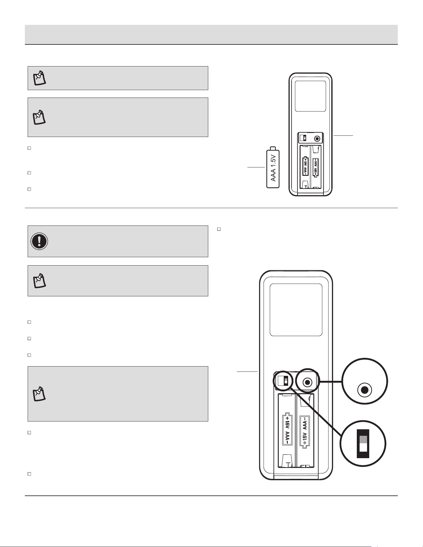
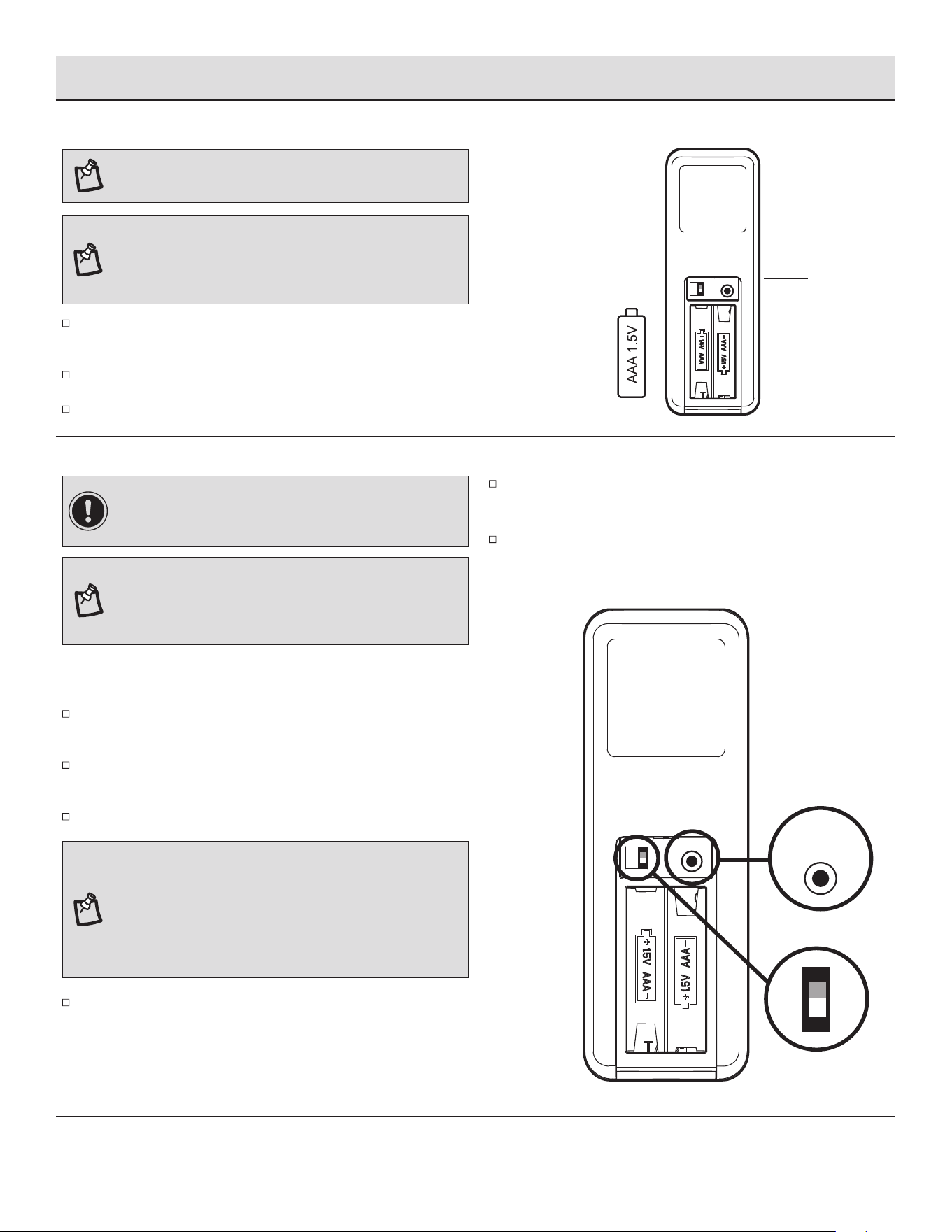
NOTE: Batteries will weaken with age and should be replaced
before leaking takes place as this will damage the remote
control. Dispose of used batteries properly and keep them out
of the reach of children.
LEARNING PROCESS
Remove the battery cover by pressing rmly on the arrow and
sliding the cover off.
Install two 1.5V AAA batteries (CC) (included).
Replace the battery cover on the remote control (L).
NOTE: If installing multiple fans on separate remotes, only
the fan being programmed should have AC power turned ON.
All other fans, even if they have already been programmed,
should have AC power OFF so they do not memorize other
remotes during the learning process. Separate the fan power
switches by approximately 2 meters.
Within 30 seconds of turning AC power on, press and release
the "LEARN" button located in the remote's battery compartment
to enter the learning function. The down light of your fan, if
applicable, will blink, and the fan blades will start to spin.
The fan will now accept commands from the added remote.
Ensure AC power to the fan is OFF to begin the learning process.
Slide the dip switch in the battery compartment to the "1" position.
Turn the fan’s AC power ON.
To add a remote to your fan’s memory, use the steps below:
CC
L
L
LEARN
1
+
0
NOTE: The remote has been pre-paired in the factory for your
convenience.
IMPORTANT: If you have two or more fans, please follow
steps below to control each fan independently. Also follow
steps below to re-pair the remote and the receiver when needed.
NOTE: The dip switch in the battery compartment has been
set on “0” position for your convenience. If you want to
re-pair the remote, please set the dip switch on “1” position.
If you would like to set the dip switch back to the "0" position
after a learning, please re-pair the remote by following the
learning process again.
16
Operation (continued)
OPERATING YOUR FAN AND REMOTE CONTROL
NOTE: The fan will store the last used speed setting for the next time it is turned on.
Correlated Color Temperature (CCT) changing.
Push and release the button to cycle through the ve color temperature
options.
Option 1: 2700K (Warm White)
Option 2: 3000K (Soft White).
Option 3: 3500K (Neutral White)
Option 4: 4000K (Bright White).
Option 5: 5000K (Daylight).
NOTE: On each start up of your ceiling fan, the fan blades will oscillate back and forth. This is a NORMAL OPERATION for DC motor ceiling
fans as they go through a calibration cycle. The fan is NOT DEFECTIVE.
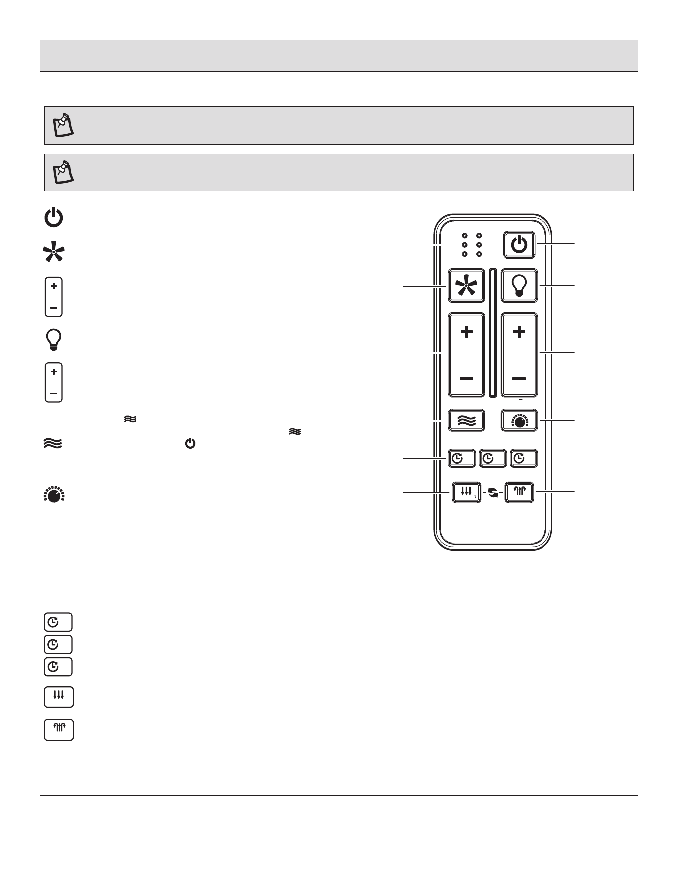
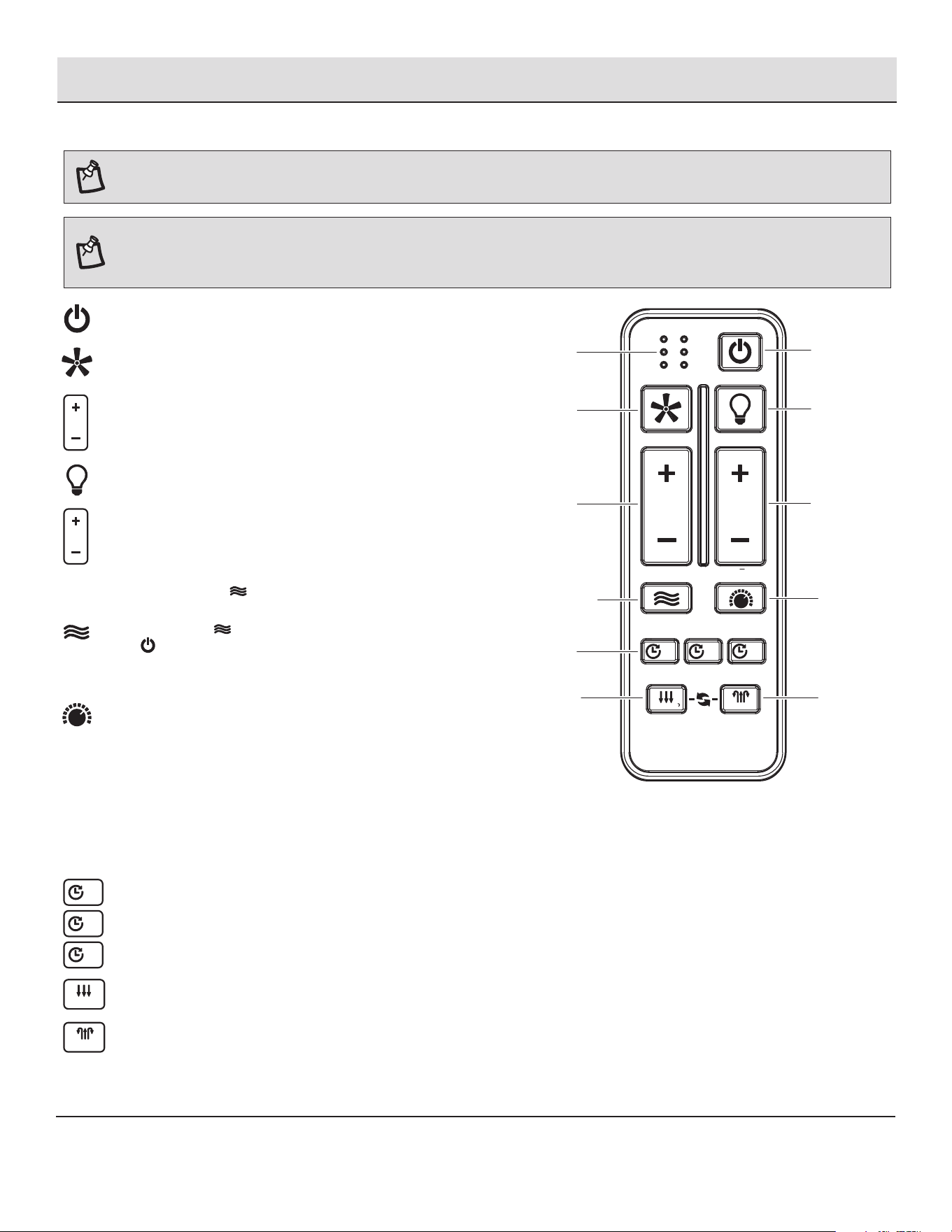
Fan ON/OFF button: Press and release this button to turn the
fan on or off.
Light ON/OFF button: Press and release this button to turn the
light on or off.
Power ALL button: Press and release the power button to turn
the fan and light on or off.
Light BRIGHTNESS button: Press and hold the “+” button to
increase the desired light level. Press and hold the “-” button
to decrease the desired light level.
Fan 6 SPEED button: Press and release the “+” button to
increases the fan speed. Press and release the “-” button to
decreases the fan speed.
TIMER
WINTER
SUMMER
FAN DIRECTION
HOLD 3 SEC.
2HR 8HR4HR
ON / OFF
ON / OFF
BREEZE
6 SPEED
BRIGHTNESS
COLOR TEMP.
ALL
Fan on/off
Fan on/
Increases /
decreases
fan speed
Comfort Breeze
TM
Timer
Signal light
Power on/off
Light on/off
Light on/
light dimming
Light color
temperature
Reverse
Forward
Pressing the timer button will automatically turn fan off
after 2, 4, or 8 hours. To cancel the timer settings, press
and hold the button three seconds and the signal light will
ash.
2HR
4HR
8HR
Forward, press and hold the button three seconds and the
signal light will ash.
SUMMER
Reverse, press and hold the button three seconds and the
signal light will ash.
WINTER
Pressing the button will activate the Comfort Breeze
TM
mode.
If you are using Comfort Breeze
TM
mode, pressing the button
for 3 seconds, pressing the button or the fan speed
buttons will cancel Comfort Breeze
TM
mode and resume
normal fan operation.
17 HAMPTONBAY.COM
Please contact 1-855-HD-HAMPTON for further assistance.
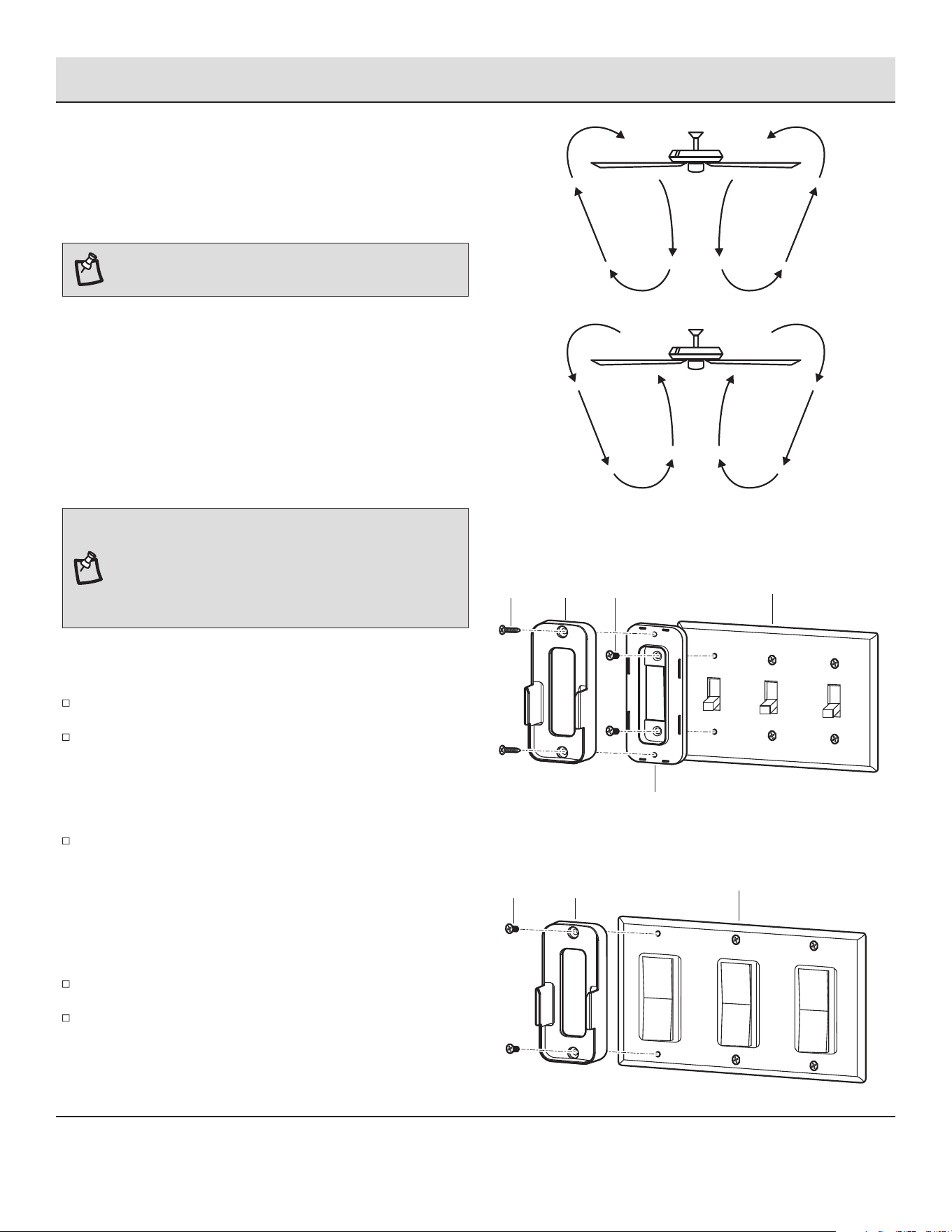
WARM/COOL WEATHER OPERATING
INSTRUCTIONS
NOTE: The fan reverse buttons must be pressed while the
fan is running.
Speed settings for warm or cool weather depend on factors such as
the room size, ceiling height, numbers of fans.
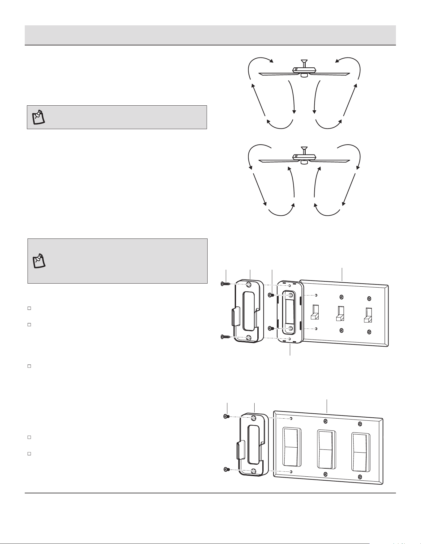
Warm weather - (Counterclockwise Direction) A downward air ow
creates a cooling effect. This allows you to set your air conditioner
on a warmer setting without affecting your comfort.
Cool weather - (Clockwise Direction) An upward air ow moves warm
air off the ceiling. This allows you to set your heating unit on a cooler
setting without affecting your comfort.
Operation (continued)
Remove the two screws from the toggle switch face plate.
Place the toggle switch spacer over the toggle switch face plate
and align the two large holes of the toggle switch spacer with
the holes in the face plate. Secure the toggle switch spacer to
the face plate using the two included machine screws (WW).
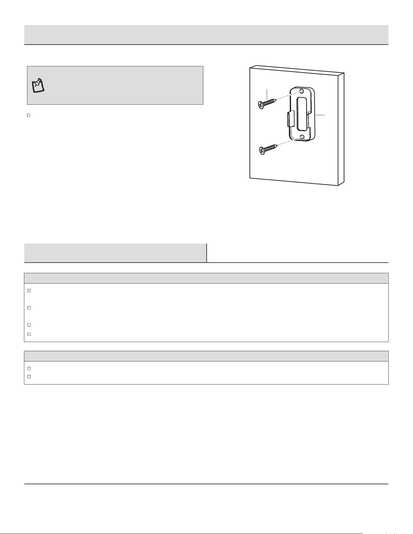
Attach the remote wall cradle (XX) to the toggle switch spacer
using the included two short tapered screws (YY). Screw a short
tapered screw (YY) into the top hole and bottom hole of the wall
cradle and into the toggle switch spacer until tight.
INSTALLING THE REMOTE CONTROL HOLDER
1a. Attaching over a standard toggle switch
Remove the two screws from the paddle switch face plate.
Place the remote wall cradle (XX) over the paddle switch and
align the two holes of the remote wall cradle (XX) with the holes
in the face plate. Secure the remote wall cradle (XX) to the face
plate using the two included machine screws (WW).
1b. Attaching over a paddle switch
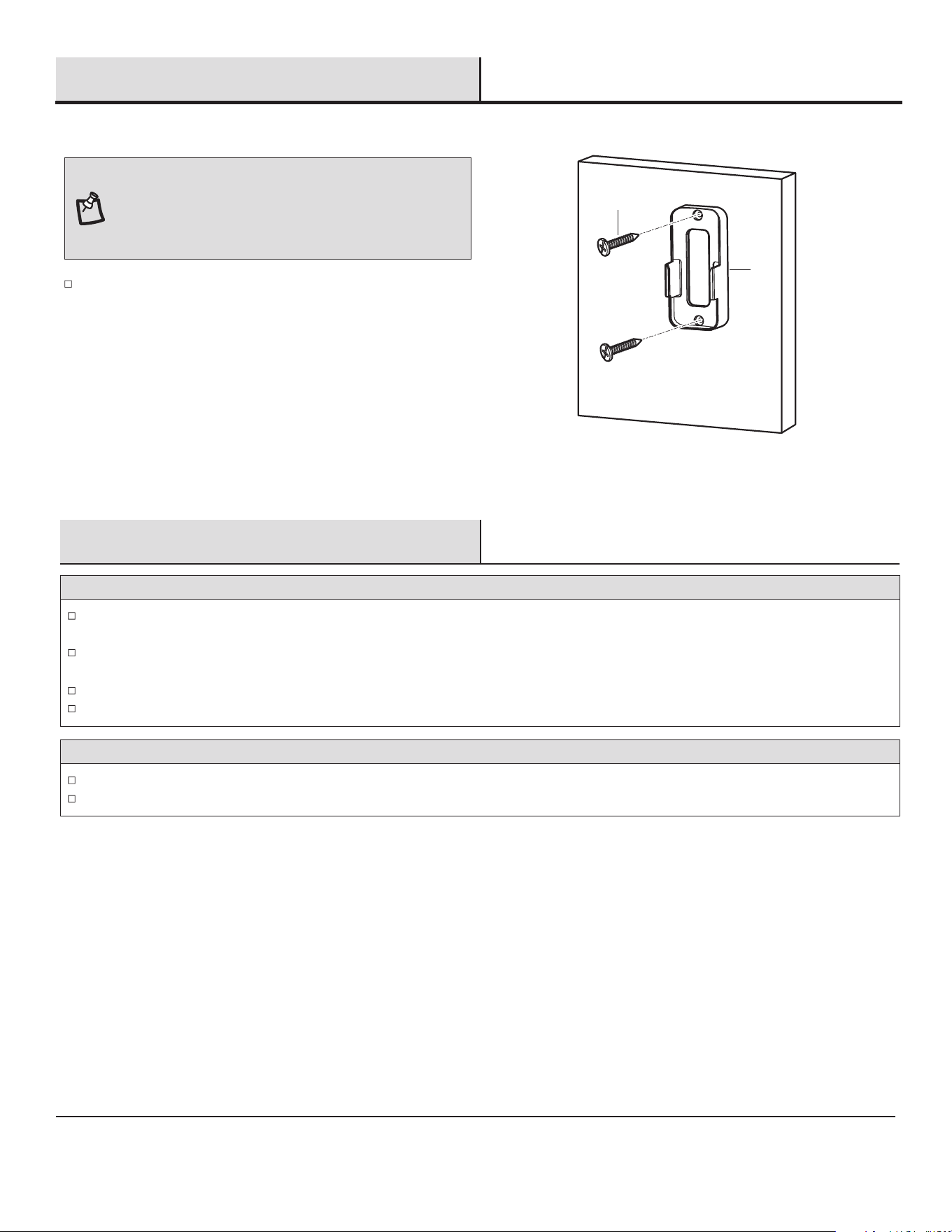
NOTE: The remote wall cradle is designed to allow you to
access an existing switch. The remote wall cradle can be
mounted on the wall or to the face plate of a standard toggle
switch or a paddle switch. Follow the instructions below for
the option that best suits your needs.
XXWW
Paddle switch face plate
Toggle switch face plate
Toggle switch spacer
WWYY XX
18
Operation (continued)
Care and Cleaning
Check the support connections, brackets, and blade attachments twice a year. Make sure they are secure. Because of the fan’s
natural movement, some connections may become loose over time. It is not necessary to remove the fan from the ceiling.
Clean your fan periodically. Use only a soft brush or lint-free cloth to avoid scratching the nish. The plating is sealed with a lacquer to
minimize discoloration or tarnishing.
(Optional) Apply a light coat of furniture polish to the wood blades.
(Optional) Cover small scratches with a light application of shoe polish.
Do
Use water when cleaning. Water could damage the motor, or the wood, or possibly cause an electrical shock.
Apply oil to your fan or motor. The motor has permanently-lubricated sealed ball bearings.
Do not
Position the remote wall cradle (XX) in the desired position and
attach to the wall using the included two long tapered screws
(ZZ).
1c. Attaching to the wall
XX
ZZ
NOTE: Screw wall anchors are included for extra support.
The included screws are designed to screw easily into the wall.
If you would like a more permanent or secure hold, install the
wall anchors prior to attaching the wall cradle to the wall.
19 HAMPTONBAY.COM
Please contact 1-855-HD-HAMPTON for further assistance.
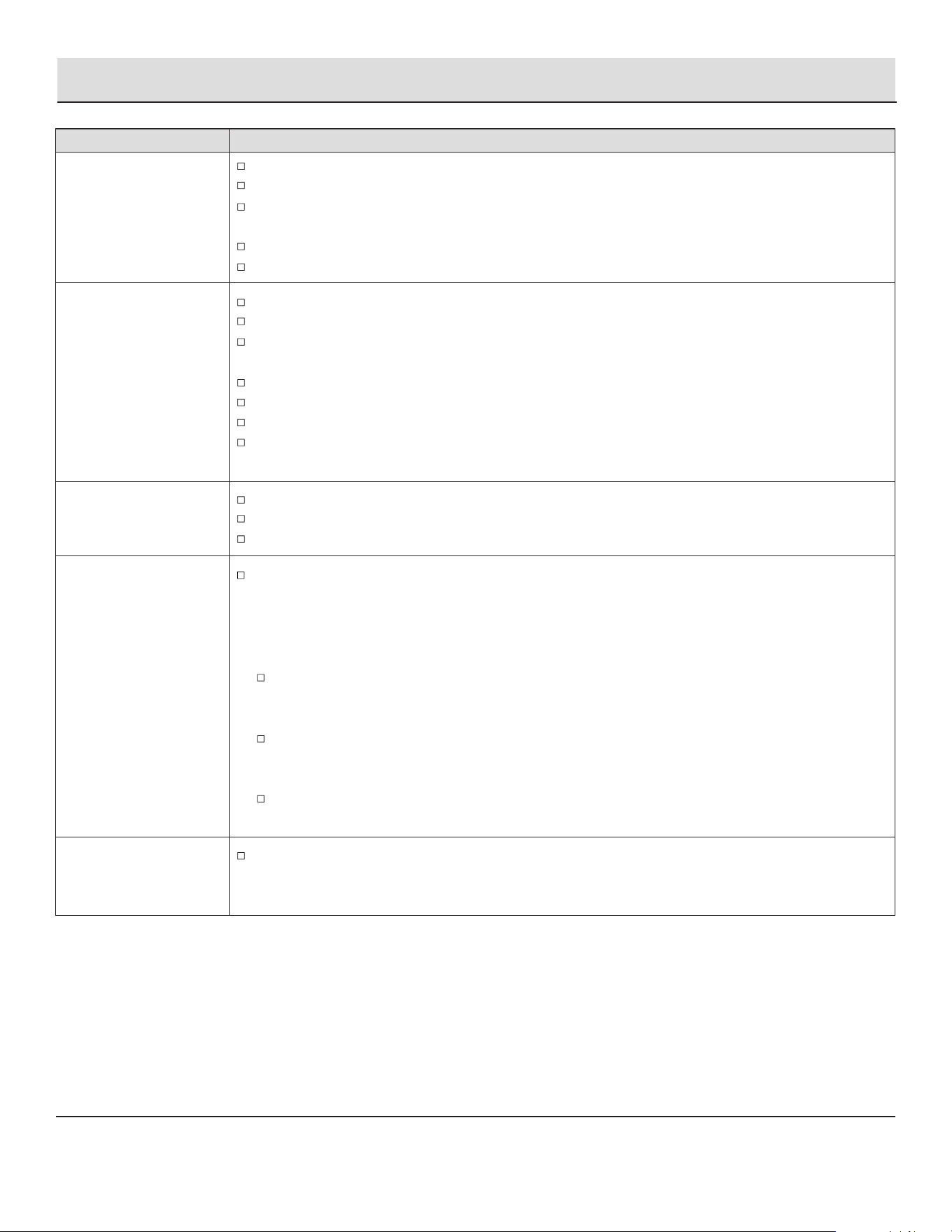
Troubleshooting
Problem Solution
The fan will not start.
Check the main and branch circuit fuses or breakers.
Check the line wire connections to the fan and switch wire connections in the switch housing.
Check to make sure the frequency switches from the remote control and receiver are set to the same
frequency.
Turn the AC power off, and turn the AC power on after 10 seconds.
Reset the transmitter by going through the transmitter “LEARNING PROCESS”.
The fan sounds noisy.
Make sure all motor housing screws are snug.
Make sure the screws that attach the fan blade to the motor hub are tight.
Make sure the wire nut connections are not rattling against each other or the interior wall of the switch
housing.
Allow a 24-hour "breaking-in" period. Most noises associated with a new fan disappear during this time.
If using the ceiling light kit, make sure the glassware is secured tightly.
Make sure there is a short distance from the ceiling to the canopy. It should not touch the ceiling.
Make sure your ceiling box is secure and that rubber isolator pads are used between the mounting
bracket and outlet box.
The remote control is
not working.
Do not connect the fan with wall mounted variable speed control(s).
Make sure the frequency switches are set correctly.
Reset the transmitter by going through the transmitter “LEARNING PROCESS”.
Fan moves backwards and
forwards when turned on.
This is normal start-up procedure for DC motor fans. The partial movement during start-up is the result
of the DC motor aligning the internal magnetic poles for proper motor operation. This design saves
electricity and allows the fan to operate much quieter than standard AC motor fans.
The fan wobbles.
Verify that all blades and blade bracket screws are secure (most fan wobble problems are caused by
loose parts). Once the fan is properly installed, run the ceiling fan for 10 minutes to let the fan
self-adjust.
If wobble occurs after running the fan for 10 minutes, verify blade level using the following process:
Select a point on the ceiling above the tip of one of the blades, then select any fan blade and measure
from the center of the selected blade to the point on the ceiling. Rotate the fan until the next blade is
positioned and repeat the measurement using the same point from the ceiling for every blade.
Measurement deviations should be within 1/8 in..
If all deviations are less than 1/8 in. and the fan continues to wobble, please call Customer Service
(1-855-HD-HAMPTON) to order a complimentary blade balancing kit.
If deviation is greater than 1/8 in., please call Customer Service (1-855-HD-HAMPTON) to order
complimentary replacements of your brackets.

Questions, problems, missing parts? Before returning to the store,
call Hampton Bay Customer Service
8 a.m. – 7 p.m., EST, Monday – Friday, 9 a.m. – 6 p.m., EST, Saturday
1-855-HD-HAMPTON
HAMPTONBAY.COM
Retain this manual for future use.
This device complies with part 15 of the FCC Rules. Operation is subject to the following two conditions: (1) This device may not cause
harmful interference, and (2) this device must accept any interference received, including interference that may cause undesired operation.
WARNING: Changes or modications to this unit not expressly approved by the party responsible for compliance could void the user's
authority to operate the equipment.
NOTE: This equipment has been tested and found to comply with the limits for a Class B digital device, pursuant to Part 15 of the FCC Rules.
These limits are designed to provide reasonable protection against harmful interference in a residential installation. This equipment generates,
uses and can radiate radio frequency energy and, if not installed and used in accordance with the instructions, may cause harmful interference
to radio communications.
However, there is no guarantee that interference will not occur in a particular installation. If this equipment does cause harmful interference
to radio or television reception, which can be determined by turning the equipment off and on, the user is encouraged to try to correct the
interference by one or more of the following measures:
- Reorient or relocate the receiving antenna.
- Increase the separation between the equipment and receiver.
- Connect the equipment into an outlet on a circuit different from that to which the receiver is connected.
- Consult the dealer or an experienced radio/TV technician for help.
GRACIAS POR TU COMPRA
GUÍA DE USO Y MANTENIMIENTO
Apreciamos la conanza que has depositado en Hampton Bay al comprar este ventilador de techo. Nos esforzamos para
continuamente crear productos de calidad diseñados para mejorar tu hogar. Visítanos por Internet para ver nuestra línea completa
de productos disponibles para las necesidades de mejoras de tu hogar. ¡Gracias por elegir Hampton Bay!
Instrucciones visuales sobre cómo instalar este ventilador:
Visite www.homedepot.com y escriba el número de artículo o modelo
para buscar este ventilador, luego haga clic en el enlace de instrucciones
visuales en la sección de descripción general del producto.
1-855-HD-HAMPTON
HAMPTONBAY.COM
¿Preguntas, problemas o piezas faltantes? Antes de regresar a la tienda, llama al
De lunes a viernes, entre 8:00 a.m. y 7:00 p.m. (Hora Estándar del Este),
y los sábados de 9:00 a.m. a 6:00 p.m. (Hora Estándar del Este).
Servicio al Cliente de Hampton Bay
1.52 m LADSHAW
VENTILADOR DE TECHO PARA INTERIORES
Artículo Núm.1010822868
1010822871
1010822869
Modelo Núm.N3329-BN
N3329-MBK
N3329-MWH
2
Índice
Índice . .........................................
Información de Seguridad ...........................
Garantía ..........................................
Pre-Instalación ....................................
Instalación .......................................
Ensamblado ......................................
Funcionamiento ...................................
Mantenimiento y Limpieza ...........................
Solución de Problemas ..............................
2
2
3
3
6
8
15
18
19
LEA Y MANTENER ESTAS INSTRUCCIONES
1.
2.
3.
4.
5.
6.
7.
8.
9.
10.
Información de Seguridad
Para disminuir el riesgo de descarga eléctrica, asegúrate de
que la electricidad ha sido apagada en el cortacircuitos o la
caja de fusibles antes de comenzar la instalación.
Todo el cableado debe cumplir con el Código Nacional de
Electricidad "ANSI/NFPA 70" y con los códigos locales de
electricidad. La instalación eléctrica debe ser hecha por un
electricista certicado y calicado.
La caja eléctrica y estructura de soporte deben montarse de
forma segura y tener capacidad para sostener de manera
conable un mínimo de 35 libras (15,9 kg). Usa solamente
cajas eléctricas aprobadas por UL marcadas como “PARA
SOPORTE DE VENTILADOR”.
El ventilador debe ir montado con un mínimo de 7 pies (2,1 m)
de separación entre el borde trasero de las aspas y el piso.
Evita colocar objetos en la trayectoria de las aspas.
Para evitar lesiones físicas o daños al ventilador y otros
artículos, ten cuidado al limpiar o trabajar cerca del ventilador.
No usar agua o detergentes al limpiar el ventilador o las aspas.
Para la limpieza, será adecuado un paño seco para quitar el
polvo o ligeramente humedecido.
Después de concluir con las conexiones eléctricas, debes
voltear los conductores empalmados hacia arriba y empujarlos
con cuidado hacia dentro de la caja eléctrica. Los cables deben
estar separados, con el cable a tierra y el conductor a tierra del
equipo hacia uno de los lados de la caja eléctrica y el conductor
sin conexión a tierra hacia el lado opuesto.
Todos los tornillos colocados se deben vericar y ajustar donde
sea necesario antes de la instalación.
Adecuado para uso con control de velocidad de estado sólido
(RH797NRZB300 solamente).
La siguiente parte responsable designada en FCC §2.909 es
responsable de esta declaración:
Modelo Número: N3329-BN, N3329-MBK, N3329-MWH
Nombre de empresa: TAL INTERNATIONAL CORPORATION
Dirección de la empresa: 2919 E. Philadelphia St., Ontario, CA 91761, U.S.A.
Número de teléfono: (909) 923-2888 Fax: (909) 923-8337
PRECAUCIÓN: Para reducir el riesgo de lesiones físicas,
usa sólo los tornillos incluidos con la caja eléctrica.
ADVERTENCIA: Para disminuir el riesgo de incendio,
descarga eléctrica o lesiones personales, monta el ventilador
sobre la caja eléctrica marcada como “aprobada como
soporte de ventilador” y usa los tornillos de montaje que
vienen con la misma.
ADVERTENCIA: No insertes objetos extraños entre las
aspas en funcionamiento.
ADVERTENCIA: Para reducir el riesgo de lesiones
personales, no dobles los brazos de las aspas (también
llamados “rebordes”) durante la instalación de los soportes,
compensación de las aspas o limpieza del ventilador.
ADVERTENCIA: Para reducir el riesgo de incendio o
descarga eléctrica, este ventilador debe instalarse con un
control/ interruptor de pared de aislamiento.
NOTE: Adecuado para su uso en lugares humedos.
60”
(1.52 m)
Baja
(Velocidad 1)
Media (Velocidad 4)
Alta (Velocidad 6)
120
Tamaño del
ventilador
Vatios RPMVelocidad Voltios Amperios PESO NETO
PIES
3
/ MIN.
Pre-Instalación
ESPECIFICACIONES
NOTA: Estas medidas son aproximadas. No incluyen ni el
amperaje ni el vataje consumido por el kit de luces.
Garantía
HERRAMIENTAS NECESARIAS
Destornillador
Phillips
Destornillador de
aspa plana
Escalera de
tijera
Pelacables
Cinta de
electricista
Llave
ajustable
3 HAMPTONBAY.COM
Para obtener asistencia, llama al 1-855-HD-HAMPTON.
El fabricante garantiza de por vida, a partir de la fecha en que el comprador original lo adquiere, que el motor del ventilador no presenta
defectos de fabricación ni de material al momento en que es enviado desde la fábrica. El fabricante garantiza, por un período de tres años
a partir de la fecha de compra por el comprador original, el kit de luces, sin incluir ningun de vidrio, no presentarán ningún defecto de
fabricación o de material desde el momento de su salida de la fábrica. El fabricante también garantiza, por el período de un año, a partir de
la fecha de compra por el comprador original, que las demás piezas del ventilador, sin incluir ninguna aspa de vidrio o acrílico, no
presen-tarán ningún defecto de fabricación o de material desde el momento de la salida de la fábrica. Acordamos reparar todos los
defectos del tipo antes mencionado, sin cargo alguno o, a nuestra discreción, reemplazar el producto por un modelo de igual calidad o
superior si el producto es devuelto. Para obtener un servicio de garantía, debe presentar una copia del recibo como comprobante de
compra. Todos los costos de retiro y reinstalación del producto son su responsabilidad. Los daños a cualquiera de las piezas como
resultado de accidentes, uso inadecuado, instalación inadecuada, o debidos a la instalación de cualquier accesorio, no están cubiertos
bajo esta garantía. Debido a que las condiciones climáticas pueden variar, esta garantía no cubre ningún cambio en el acabado en bronce,
incluyendo óxido, perforación, corrosión, manchas o descascaramiento. Los acabados en bronce de este tipo tienen una vida útil más
prolongada cuando se protegen de las condiciones climáticas cambiantes. Es normal cierta “oscilación” y no se considerará una falla.
Cualquier servicio técnico realizado por personas no autorizadas invalidará la garantía. No hay ninguna otra garantía expresa. Mediante la
presente, nos eximimos de cualquier garantía, incluyendo pero sin limitarnos a aquellas de comercialización e idoneidad para un n
particular, de acuerd a lo contemplado por la ley. La duración de cualquier garantía implícita de la cual no se pueda eximir está limitada al
período de tiempo especicado en la garantía explícita. Algunos estados no permiten limitaciones a la duración de la garantía, por
consiguiente a limitación anterior puede no aplicarse a su caso. El minorista no será responsable por daños directos, indirectos o
especiales que resulten o deriven del uso o rendimiento del producto excepto en casos en que lo estipule la ley. Algunos estados no
permiten la exclusión o limitación de daños directos o indirectos, por lo que la limitación o exclusión anterior podría no aplicarse a su caso.
Esta garantía le otorga derechos legales especícos y es posible que también tenga otros derechos que varían de un estado a otro. Esta
garantía sustituye todaslas garantías anteriores. Los costos de envío de cualquier devolución de productos hecha como parte de una
reclamación de garantía están a cargo del cliente.
Comuníquese con el Equipo de Servicio al Cliente al 1-855-HD-HAMPTON o visite www.hamptonbay.com.
0.07
0.32
0.65
4.74
19.50
45.40
49
121
169
2373
6346
8986
9.7 kg
(21.34 lb)

4
NOTA: El hardware no se muestra en tamaño real.
AA
BB
CC
DD
EE
FF
Tuerca de conexión de cables de plástico
Tornillo de mondtje del soporte de aspa y arandela de seguridad
Batería AAA de 1.5V
Cable de extensión de 2-pine
Cable de extensión de 3-pine
Tornillo de jación de aspas y arandela de seguridad (adicional)
Pieza Descripción
3
3
2
1
1
1
Cantidad
Pre-Instalación (continuación)
HERRAJES INCLUIDOS
AA
EE
CCBB
DD
FF
5
Pieza
I
J
K
L
Cantidad
5
1
1
1
Descripción
Placa de soporte para las aspa con
tornillo y arandela de seguridad
Aspa
Ensamblado de kit de luces LED de 24W
Receptor
Control remoto
CONTENIDO DEL PAQUETE
Pre-Instalación (continuación)
HAMPTONBAY.COM
Para obtener asistencia, llama al 1-855-HD-HAMPTON.
Pieza
A
B
C
D
E
F
G
Cantidad
1
1
1
1
1
1
1
Descripción
Soporte de montaje
Cubierta
Tapa del fondo de la cubierta (preensamblado)
Ensamblado de tubo bajante/bola de soporte
Cubierta del acoplamiento
Ensamblaje del motor del ventilador
Soporte de aspa
K L
J
A
D
E
B
C
TIMER
WINTER
SUMMER
FAN DIRECTION
HOLD 3 SEC.
2HR 8HR4HR
ON / OFF
ON / OFF
BREEZE
6 SPEED
BRIGHTNESS
COLOR TEMP.
ALL
I
H
5H
G
F

6
Si tu ventilador de techo no posee una caja de montaje aprobada
por UL, instala una siguiendo las instrucciones a continuación:
Desconecta la energía retirando los fusibles o apagando los
cortacircuitos.
Fija la caja eléctrica (no provistas) directamente a la estructura
del edicio. Usa sujetadores y materiales (no provistas)
apropiados. La caja eléctrica y su soporte deben sostener
completamente el peso en movimiento del ventilador (al
menos 35 libras). No uses una caja eléctrica de plástico.
Las ilustraciones a continuación muestran tres formas diferentes
de montar la caja eléctrica (no provistas).
Para colgar el ventilador donde ya haya una lámpara pero
ninguna viga de techo, tal vez necesites una barra de instalación
colgante (no provistas) como se muestra arriba.
Caja Eléctrica
Caja Eléctrica
Barra Para Colgar
Caja Eléctrica
Caja Eléctrica
Empotrada
A
ADVERTENCIA: Para disminuir el riesgo de incendio,
descarga eléctrica o lesiones personales, monta el ventilador
sobre una caja eléctrica marcada como “aprobada como
soporte de ventilador” y usa los tornillos de montaje que
vienen con la misma. Las cajas eléctricas utilizadas
comúnmente para el soporte de artículos de iluminación
pueden no servir como soporte de ventilador, y tal vez deban
reemplazarse. En caso de duda, consulta a un electricista
calicado.
OPCIONES DE MONTAJE
Instalación
NOTA: Tal vez necesites un tubo bajante más largo para
mantener la altura mínima adecuada de las aspas al instalar
el ventilador en un techo inclinado. El ángulo máximo permitido
es de 18º de la posición horizontal. Si la cubierta (B) toca el
ensamblado de tubo bajante/bola de soporte (D), retira la tapa
inferior decorativa de la cubierta (C) y gira la cubierta (B) 180º
antes de jarla (B) al soporte de montaje (A).
7
Ensamblado
1
Cómo preparar la cubierta
Retira la tapa del fondo de la cubierta (C) de la cubierta (B),
girando la cubierta del fondo de la cubierta (C) hacia la
izquierda.
Retire el soporte de montaje (A) de la cubierta (B) aojando
los tornillos de montaje de la cubierta (GG) media vuelta
desde la cabeza del tornillo. Luego, gira la cubierta (B) hacia
la izquierda para retirar el soporte de montaje (A) de la
cubierta (B).
HAMPTONBAY.COM
Para obtener asistencia, llama al 1-855-HD-HAMPTON.
2
Cómo montar las aspas del ventilador
□ Comience utilizando el embalaje original del producto
para crear una base para sujetar la placa porta aspas (G).
Coloque la placa porta aspas (G) con la parte inferior
hacia arriba.
□ Lleve una aspa del ventilador (I) a la placa porta aspas (G)
y asegúrese de que el lado "ARRIBA" esté hacia arriba.
Coloque la aspa (I) sobre la placa porta aspas (G) y alinéela
con los oricios que se encuentran debajo.
□ Coloque una placa de soporte de la aspa (H) con tornillos
sobre los oricios y apriete todos los tornillos
rmemente. Repita este procedimiento con las aspas
restantes (I).
Embalaje de la pulpa
H
I
G
GG
A
GG
B
C
8
Ensamblado (continuación)
3a
Cómo ajustar los ensamblajes
de las aspas al motor
Coloque el motor del ventilador (F) con la parte inferior
hacia arriba utilizando el embalaje original del producto, y
aoja tres tornillos (HH) en la motor del ventilador. (No
retirar).
Alinee la etiqueta de echa del soporte de las aspas con la
del motor del ventilador. Coloque los oricios del soporte de
las aspas sobre los tres tornillos (HH) del motor del ventilador
y deslízalos hasta que los tres tornillos (HH) queden jos en
su lugar en la sección estrecha. Apriete los tres tornillos.
3b
Cómo ajustar los ensamblajes
de las aspas al motor
Instale tres tornillos del soporte de la aspa con arandelas
de seguridad (BB) en los tres oricios para tornillos y
asegúrese de que estén bien apretados.
ADVERTENCIA: Para reducir el riesgo de lesiones
personales, no doblar los brazos del aspa (H) durante la
instalación, compensación de las aspas (I) o limpieza del
ventilador. No insertes objetos extraños entre las aspas (I)
en funcionamiento.
F
HH
HH
Flecha
HH
Flecha
BB
BB
BB
I
9
HAMPTONBAY.COM
Para obtener asistencia, llama al 1-855-HD-HAMPTON.
5
4
Cómo preparar el motor
Ensamblado (continuación)
Cómo ensamblar el ventilador
□ Da la vuelta al motor. Retira el pasador de chaveta (II) y
pasador tipo horquilla (JJ), y aoja los dos tornillos de
ajuste de collarín (KK) del collarín del motor.
□ Retira el tornillo de jación (LL) de la bola de soporte
(MM), bájala y retira el pasador transversal (NN). Quita
la bola de soporte (MM) del ensamblaje del tubo
bajante/bola de soporte (D).
□ Retira la cable de tierra (OO) del ensamblaje del tubo de
soporte (D).
ADVERTENCIA: Si no instalas correctamente el pasador
de chaveta (II) es posible que el ventilador se aoje y caiga.
NOTA: Si necesita una bajante más larga (no incluida), retire
el tornillo de bola de sorporte (MM), bájelo y retire el pasador
(NN). Retire las tres piezas de la bajante y únalas en una
nueva bajada más larga antes de continuar con la instalación
de la bajada. Asegúrese de unir los conectores de 2-pine y 3-
pine, los dos enchufes macho del ventilador y el enchufes
hembra del cables de extensión (DD y EE).
NOTA: NO instale cables de extensión (DD y EE) cuando utilice
el bajante incluido.
□ Con cuidado, introduce los cables del motor hacia
arriba a través del tubo bajante (PP). Enrosca el tubo
bajante (PP) en el collarín.
□ A continuación, alinea los oricios y reemplaza el
pasador tipo horquilla (JJ) y el pasador de chaveta (II).
Ajusta los dos tornillos de jación del collarín (KKJ).
□ Desliza la cubierta del acoplamiento (E), el base de la
cubierta (C) y la cubierta (B) hacia el tubo bajante (PP).
□ Con cuidado, vuelve a colocar la bola de soporte (MM) y
la cable de tierra (OO) sobre el tubo bajante (PP).
Asegúrate de que el pasador transversal (NN) esté en la
posición correcta, el tornillo de jación (LL) esté
ajustado y los cables no estén torcidos.
II
JJ
KK
KK
F
LL
D
NN
MM
OO
KK
KK
F
II
C
E
B
LL
NN
MM
PP
OO
JJ
EE
DD
10
Ensamblado — Cómo Colgar el Ventilador
Caja Eléctrica
A
6
Cómo instalar el soporte de
montaje en la caja eléctrica
7
Cómo colgar el ventilador
al soporte de montaje
□ Levante con cuidado el ensamblaje del motor (F) hacia el
soporte de montaje (A) y encaja la ensamblado de tubo
bajante/bola de soporte (D) en el socket del soporte de
montaje (A). Asegúrate de que la pestaña sobre el socket
de soporte de montaje (A) encaje bien dentro de la ranura
del ensamblado de tubo bajante/bola de soporte (D). Esto
ayudará a compensar el ventilador de techo.
ADVERTENCIA: Para disminuir los riesgos de incendio,
descarga eléctrica o lesiones personales. Monta el ventilador
sólo sobre una caja eléctrica o sistema de soporte marcado
como “aprobada como soporte de ventilador” y usa los
tornillos de montaje que vienen con la caja eléctrica.
ADVERTENCIA: La pestaña en el anillo debe encajar en la
ranura de la ensamblado de tubo bajante/bola de soporte (D).
Si la pestaña no se asienta correctamente en la ranura, se
puede dañar el cableado.
□ Pasa los cables de suministro de 120 voltios a través
del oricio central en el soporte de montaje (A).
□ Monta el soporte de montaje (A) sobre la caja
eléctrica deslizando el soporte de montaje (A) sobre
los tornillos suministrados con la caja eléctrica. Fíjate
que el lado plano del soporte de montaje (A) esté
hacia la caja eléctrica.
□ Ajusta rmemente los dos tornillos de montaje.
Ver después de la instalación
8
Instalación del receptor
□ Coloque el cable negro del suministro doméstico en un
lado del soporte de montaje (A) y coloque los cables
blanco y verde del suministro doméstico en el lado
opuesto.
□ Empuje el cable amarillo de la antena a través del
soporte de montaje (A) e inserte el extremo angosto
del receptor (K) (como se muestra, con el lado plano
hacia el techo) en el soporte de montaje deslizante (A)
hasta que descanse sobre el conjunto de bola/varilla.
ADVERTENCIA: Para reducir el riesgo de incendio o descarga
eléctrica, recuerde desconectar la alimentación. El cableado
eléctrico debe cumplir con todos los requisitos de los códigos
eléctricos locales y nacionales. La fuente eléctrica y el ventilador
deben ser de 120 voltios, 60Hz. No utilice este producto junto con
ningún control de pared variable. Una conexión de cables
incorrecta puede dañar este receptor.
D
F
A
K
Pestaña
A
11 HAMPTONBAY.COM
Para obtener asistencia, llama al 1-855-HD-HAMPTON.
Ensamblado — Cómo Colgar el Ventilador (continuación)
9a
Cómo hacer las conexiones eléctricas
NOTA: El ventilador debe instalarse a una distancia máxima
de 6,1 m de la unidad transmisora para obtener una señal de
transmisión apropiada entre la unidad transmisora y la unidad
receptora del ventilador.
ADVERTENCIA: Verica que todas las conexiones estén
bien ajustadas, incluida la conexión a tierra, y que no haya
ningún cable pelado visible en las tuercas para cable (excepto
el de tierra).
Si crees que no tienes suciente experiencia o conocimientos
en cableado eléctrico, contrata a un electricista con licencia para
que instale el ventilador.
Sigue estos pasos para conectar tu ventilador a tu circuito
doméstico. Usa las tuercas de plástico para cable (AA) con tu
ventilador. Asegura las tuercas de cables (AA) con cinta de
electricista. Asegúrate de que no haya conexiones o cables sueltos.
Haga las conexiones de cables desde el ventilador al receptor (K).
Del ventilador Al receptor
Conector de 2-pine --------------- Conector de 2-pine
Conector de 3-pine --------------- Conector de 3-pine
Haga las conexiones de cables desde el receptor (K) y el
ventilador a la caja de eléctrica de la siguiente manera,
utilizando las tuercas para cables (AA).
Del receptor A la caja de eléctrica
Cable negro "CA en L" +
Cable rojo "para luz" ------------- Cable negro (caliente)
Cable blanco "CA en N" ---------- Cable blanco (neutro)
Del ventilador y receptor A la caja de eléctrica
Cables verdes* ------------------ Cable verde o desnudo
(tierra)
* Hay tres cables de conexion a tierra verdes: uno del soporte de
montaje (A), otro del conjunto de bola de suspension/varilla (D) y
uno del receptor (K).
Gire las conexiones de la tuerca del cable hacia arriba,
separándolas de modo que el cable verde (tierra) y el cable
blanco estén en un lado de la caja de eléctrica y el cable
negro en el otro lado. Introduzca con cuidado las conexiones
en la caja eléctrica.
PRECAUCIÓN: Para reducir el riesgo de incendio o descarga
eléctrica, este ventilador debe instalarse con un control/interruptor
de pared de aislamiento.
AA
Conectores de
2-pine y 3-pine
Verde
Verde
Caja Eléctrica
D
Negro
Conductor
a tierraBlanco
A
Rojo
Negro
Blanco
K
12
Ensamblado — Cómo Colgar el Ventilador (continuación)
9b 9c
Conexiones de un solo interruptor Conexiones de interruptor doble
Con un solo interruptor, el ventilador y la luz se pueden
encender o apagar juntos. Realice las conexiones de cables
de la siguiente manera, utilizando las tuercas para cables (AA).
Interruptor de pared no incluido.
Del Ventilador A la Caja de Eléctrica
Cables negro + rojo --------- Negro alambre (caliente)
Cable blanco ----------------- Cable blanco (neutro)
Cables verdes* -------------- Cable verde o desnudo (tierra)
En un interruptor doble, el ventilador y la luz se pueden
encender o apagar por separado. Realice las conexiones de
cables de la siguiente manera, utilizando las tuercas para
cables (AA). Interruptor de pared no incluido.
Del Ventilador A la Caja de Eléctrica
Cable negro (para ventilador) --- Negro alambre (caliente #1)
Cable roja (para luz) ----------- Roja alambre (caliente #2 pero
tal vez sea de otro color que
no sea negro, blanco o verde)
Cable blanco ------------------ Cable blanco (neutro)
Cables verdes * --------------- Cable verde o desnudo (tierra)
INTERRUPTOR
SENCILLO
Conductor
a tierra
Blanco
Conectores
de 4-pine y
3-pine
INTERRUPTORE
DOBLE
AC IN
AA
J
D
A
Conectores
de 4-pine y
3-pine
Negro
Blanco
Caja Eléctrica
Verde
Verde
Rojo
AC IN
AA
D
A
J
Verde
Conductor
a tierra
Blanco
Negro
Roja
Caja Eléctrica
Verde
Blanco
Rojo
Negro
Negro
13 HAMPTONBAY.COM
Para obtener asistencia, llama al 1-855-HD-HAMPTON.
Cómo sujetar la tapa del fondo de la
cubierta
11
Ensamblado — Cómo Colgar el Ventilador (continuación)
10
Cómo instalar la cubierta
Coloca todas las conexiones apropiadamente en la caja
eléctrica del techo.
Desliza la cubierta (B) hacia el soporte de montaje (A) y
coloca el oricio tipo ojo de la cerradura en la cubierta
sobre el tornillos de montaje de la cubierta (GG) suelto en el
soporte de montaje (A). Gira la cubierta hacia la derecha
hasta que caiga en su lugar en la parte estrecha de los
oricios tipo ojo de la cerradura. Asegúrese de que el
pasador de posicionamiento (QQ) del soporte de montaje cae
en uno de los dos agujeros (RR) de la cubierta, y luego
apriete los dos tornillos de montaje de la cubierta (GG).
ADVERTENCIA: Asegúrate de que la pestaña sobre el
soporte de montaje (A) encaje bien dentro de la ranura de la
bola de soporte (LL) antes de sujetar la cubierta (B) al soporte
de montaje (A), girando la carcasa de la cubierta hasta que
encaje en su lugar.
NOTA: Ajusta los tornillos de montaje de la cubierta (GG)
según sea necesario hasta que la cubierta (B) y la tapa inferior
de la cubierta (C) estén ajustadas.
Sujeta la tapa inferior de la cubierta (C) a la cubierta (B)
insertando las cabezas de tornillos en las ranuras en forma
de cerradura en la tapa inferior de la cubierta (C) y rotándola
hacia la derecha.
Caja Eléctrica
QQ
GG
A
B
C
GG
RR
C
B
GG
14
Cómo instalar las ensamblado de
kit de luz a la placa de montaje del
kit de luces
12
Ensamblado — Cómo Instalar el Kit de Luces
PRECAUCIÓN: Antes de empezar la instalación, corta el
suministro de electricidad, apagando el cortacircuitos o
retirando el fusible en la caja de fusibles. Cortar el suministro
de electricidad con el interruptor del ventilador no es suciente
para evitar una descarga eléctrica.
Mientras sostienes el kit de luces de 24W (J) debajo del
ensamblaje del motor del ventilador (F), monte el enchufe
de conexión de los alambres (SS):
Blanco con blanco
Negro con negro
Coloque las muescas (TT) del borde interior de la ensamblado
de kit de luces LED de 24W (J) de manera que queden alineadas
con las pestañas (UU) en el interno del borde en la placa de
montaje del kit de luces (VV) y fíjelo al ventilador girando la
ensamblado de kit de luces LED de 24W (J) en el sentido de
las agujas del reloj hasta que quede ajustado.
NOTA: Si el kit de luces se tambalea con la mano, signica
que el kit de luces no se ha girado completamente hasta la
posición correcta. Siga girando el kit de luces hasta que no se
pueda mover con la mano.
J
TT
SS
UU
VV
F
15 HAMPTONBAY.COM
Para obtener asistencia, llama al 1-855-HD-HAMPTON.
CONFIGURAR EL TRANSMISOR
Funcionamiento
NOTA: Las pilas se debilitarán con el tiempo y deben
reemplazarse antes de que se produzca una fuga, ya que esto
dañará el mando a distancia. Deseche las pilas usadas
adecuadamente y manténgalas fuera del alcance de los niños.
PROCESO DE RECONOCIMIENTO
Quita la cubierta de la batería presionando con rmeza en la
echa y deslizando la cubierta hasta soltarla.
Instala 2 baterías AAA de 1.5 V (CC) (incluidas).
Coloca de nuevo la cubierta en el control remoto (L).
NOTA: Si se instalan varios ventiladores con mandos a distancia
separados, sólo el ventilador que se está programando debe
tener la alimentación de CA encendida. El resto de ventiladores,
incluso si ya han sido programados, deben tener la alimentación
de CA apagada para que no memoricen otros mandos durante
el proceso de reconocimiento. Separe los interruptores de
alimentación de los ventiladores aproximadamente 2 metros.
Asegúrese de que la alimentación de CA del ventilador esté
desactivada para comenzar el proceso de reconocimiento.
Deslice el interruptor DIP del compartimento de la batería a la
posición "1".
Encienda la alimentación de CA del ventilador.
Para agregar un mando a la memoria de su ventilador, siga estos
pasos:
LEARN
1
+
0
CC
L
NOTA: El control remotal se ha emparejado previamente en la
fábrica para su comodidad.
IMPORTANTE: También siga los pasos siguientes para
volver a emparejado el control remoto y el receptor cuando
sea necesario.
NOTA: El interruptor DIP en el compartimiento de la batería
se ha congurado en la posición "0" para su comodidad. Si
desea volver a emparejar el control remoto, congure el
interruptor DIP en la posición "1".
En 30 segundos después de encender la alimentación de CA,
presione y suelte el botón "LEARN" (Aprender) ubicado en el
compartimento de la batería del control remoto para entrar en la
función de aprendizaje. Una vez que el ventilador ha detectado
la frecuencia del mando a distancia, la luz de su ventilador, si
tiene, parpadeará y las palas del ventilador comenzarán a girar.
El ventilador ahora aceptará los comentarios del control remoto
añadido.
Si desea volver a congurar el interruptor DIP en la posición
"0" después de un aprendizaje, vuelva a emparejar el control
remoto siguiendo el proceso de aprendizaje nuevamente.
LEARN
1
+
0
L
LEARN
1
+
0
16
Funcionamiento (continuación)
CÓMO USAR TU VENTILADOR Y EL CONTROL
REMOTO
NOTA: El ventilador almacenará el último ajuste de velocidad utilizado para la próxima vez que se encienda.
NOTA: En cada puesta en marcha el ventilador de techo que las aspas oscilarán de ida y vuelta. Esta es una operación normal de los
ventiladores de techo para motor de corriente continua a medida que avanzan a través de un ciclo de calibración. El ventilador no está
defectuoso.
Presione y suelte el botón para recorrer los cinco colores opciones
de temperatura.
Opción 1: 2700K (blanco cálido)
Opción 2: 3000K (blanco suave).
Opción 3: 3500K (blanca neutral)
Opción 4: 4000K (blanco brillante).
Opción 5: 5000K (luz blanca).
Temperatura de color correlacionada (CCT) cambiando
Al presionar el botón del temporizador, el ventilador se
apagarán automáticamente después de 2, 3 u 8 horas.
Para cancelar la conguración del temporizador,
mantenga presionado el botón durante tres segundos y la
luz de señal parpadeará.
2HR
4HR
8HR
Botón de ON/OFF del ventilador: Presione y suelte este botón
para encender o apagar el ventilador.
Botón de ON/OFF de la luz: Presione y suelte este botón para
encender o apagar la luz.
Botón de encendido ALL: presione y suelte el botón de
encendido para encender o apagar el ventilador y la luz.
Botón de BRIGHTNESS del luz: Mantenga presionado el botón
“+” para aumentar el nivel de luz deseado. Mantenga
presionado el botón “-” para disminuir el nivel de luz.
Botón 6 SPEED del ventilador: presione y suelte el botón “+”
para aumentar la velocidad del ventilador. Presione y suelte
el botón “-” para disminuir la velocidad del ventilador.
Hacia adelante, mantenga presionado el botón tres segundos
y la luz de señal parpadeará.
SUMMER
Reversa, mantenga presionado el botón tres segundos y la
luz de señal parpadeará.
WINTER
TIMER
WINTER
SUMMER
FAN DIRECTION
HOLD 3 SEC.
2HR 8HR4HR
ON / OFF
ON / OFF
BREEZE
6 SPEED
BRIGHTNESS
COLOR TEMP.
ALL
Encendido /
apagado el
ventilador
Encendido /
Aumenta /
disminuye
la velocidad
del ventilador
Comfort Breeze
TM
Temporizador
Luz de señal
Encendido /
apagado
Encendido /
apagado la luz
Encendido/
atenuación
de la luz
Temperatura
de color del
luz
ReversaHacia adelante
Al presionar el botón , se activará el modo Comfort
Breeze
TM
. Si está utilizando el modo Comfort Breeze
TM
, al
presionar el botón durante 3 segundos, al presionar el
botón o los botones de velocidad del ventilador se
cancelará el modo Comfort Breeze
TM
y se reanudará el
funcionamiento normal del ventilador.
17 HAMPTONBAY.COM
Para obtener asistencia, llama al 1-855-HD-HAMPTON.
Funcionamiento (continuación)
NOTA: Los botones de inversión del ventilador deben ser
presionados mientras el ventilador está funcionando.
Clima cálido - (Hacia la izquierda) Un ujo de aire hacia abajo crea
un efecto refrescante. Esto te permite jar tu aire acondicionado
en una conguración más alta sin afectar tu comodidad.
Clima frío - (Hacia la derecha) Un ujo de aire hacia arriba mueve
el aire cálido lejos del techo. Esto te permite jar tu unidad de
calefacción en una conguración más baja sin afectar tu comodidad.
Los ajustes de velocidad para clima cálido o frío dependen de
factores como el tamaño de la habitación, la altura del techo, la
cantidad de ventiladores.
INSTRUCCIONES DE OPERACIÓN DE TIEMPO
CÁLIDO/FRÍO
CÓMO INSTALAR EL SOPORTE DEL CONTROL
REMOTO
La placa frontal del
interruptor de palanca
La placa frontal del
interruptor de paleta
Separador del interruptor
de palanca
Retira los dos tornillos de la placa frontal del interruptor de palanca.
Coloca el separador del interruptor de palanca sobre el interruptor
de palanca y alinea los dos agujeros grandes del separador del
interruptor de palanca con los agujeros de la placa frontal. Fi ja
el espaciador del interruptor de palanca a la placa frontal con
los dos tornillos maquinados incluidos (WW).
Fija el soporte de pared remoto (XX) al espaciador del
interruptor de palanca utilizando los dos tornillos cónicos cortos
(YY) incluidos. Atornilla un tornillo cónico corto (YY) en el oricio
superior y en el inferior del soporte de pared y en el espaciador
del interruptor de palanca hasta que quede apretado.
1a. Conexión sobre un interruptor de palanca
estándar
Retira los dos tornillos de la placa frontal del interruptor de paleta.
Coloca el soporte de pared remoto (XX) sobre el interruptor de
paleta y alinea los dos oricios del soporte de pared remoto (XX)
con los oricios de la placa frontal. Fija el soporte de pared
remoto (XX) a la placa frontal con los dos tor nillos maquinados
incluidos (WW).
1b. Conexión sobre un interruptor de pala
NOTA: El soporte de pared remoto está diseñado para
permitirte acceder a un interruptor existente. El soporte de
pared remoto puede montarse en la pared o en la placa frontal
de un interruptor de palanca estándar o de un interruptor de
paleta. Sigue las siguientes instrucciones para la opción que
mejor se adapte a tus necesidades.
XXWW
WWYY XX
18
Revisa las conexiones de soporte, soportes y accesorios de aspas dos veces al año. Verica que estén seguros. Debido al movimiento
natural del ventilador, algunas conexiones pueden aojarse con el tiempo. No es necesario desmontar el ventilador del techo.
Limpia tu ventilador con frecuencia. Usa solamente un cepillo suave o un paño sin pelusas para evitar arañar el acabado. El revestimiento
está sellado con laca para minimizar la decoloración u opacidad.
(Opcional) Aplica una na capa de pulimento para muebles a la madera de las aspas.
(Opcional) Cubre los arañazos pequeños con una leve aplicación de lustrador para calzado.
Hacer
Mantenimiento y Limpieza
Uses agua al limpiarlo. El agua puede dañar el motor o la madera, o causar descargas eléctricas.
Apliques lubricador al ventilador o al motor. El motor tiene cojinetes de bola sellados permanentemente lubricados.
No hacer
Funcionamiento (continuación)
Coloca el soporte de pared remoto (XX) en la posición deseada y
fíjalo a la pared con los dos tornillos cónicos largos (ZZ)
incluidos.
1c. Montaje en la pared
NOTA: Se incluyen anclajes de pared con tornillos para soporte
adicional. Los tornillos incluidos están diseñados para atornillarse
fácilmente en la pared. Si deseas una sujeción más permanente
o segura, instala los anclajes de pared antes de jar el soporte
de pared a la pared.
XX
ZZ
19 HAMPTONBAY.COM
Para obtener asistencia, llama al 1-855-HD-HAMPTON.
Solución de Problemas
Problema Solución
El ventilador no
enciende.
Verica fusibles o disyuntores principales y secundarios.
Verica conexiones de cables en línea al ventilador y conexiones de cables del interruptor en la caja del
interruptor.
Revisa para asegurarte de que los interruptores de frecuencia del control remoto y del receptor estén
congurados en la misma frecuencia.
Apague la alimentación de CA, y encienda la alimentación de CA después 10 segundos.
Restablezca el transmisor pasando por el “PROCESO DE RECONOCIMIENTO” del transmisor.
El ventilador hace ruido.
Asegúrate de que los tornillos de la carcasa del motor estén ajustados.
Asegúrate de que los tornillos que unen el brazo del aspa del ventilador al cuerpo del motor están bien
ajustados.
Asegúrate de que las conexiones de tuerca de cable no choquen unas con otras o con la pared interior de
la caja del interruptor.
Permite un período de 24 horas de “adaptación”. La mayoría de los ruidos asociados con un nuevo ventilador
desaparecen en ese período.
Si usas el kit de luces de techo, asegúrate de que los tornillos sujetadores estén bien ajustados. Verica
que la bombilla también esté bien asegurada.
Asegúrate de que la cubierta esté a corta distancia del techo. No debería tocar el techo.
Asegúrate de que tu caja del techo esté bien segura y las almohadillas aislantes de goma se hayan instalado
entre el soporte de montaje y la caja eléctrica.
No conecte el ventilador con un control en la pared de velocidad variable(s).
Asegúrate de que los interruptores de frecuencia estén congurados correctamente.
Restablezca el transmisor pasando por el “PROCESO DE RECONOCIMIENTO” del transmisor.
El control remoto
no funciona.
El ventilador oscila.
Verica que todas las aspas y los tornillos de los soportes de aspas estén seguros (la mayoría de los
problemas de oscilación del ventilador se deben a piezas sueltas). Una vez que el ventilador ha sido instalado
correctamente, enciéndelo durante 10 minutos para que se autoajuste.
Si luego de 10 minutos de estar encendido el ventilador aún oscilara, verica el nivel de las aspas utilizando
el siguiente procedimiento:
Ubica un punto en el techo sobre la punta de una de las aspas, luego elige cualquier aspa del ventilador
y mide desde el centro del aspa seleccionada hasta el punto en el techo. Rota el ventilador hasta que la
siguiente aspa esté posicionada y repite la medición utilizando el mismo punto en el techo para cada aspa.
Las desviaciones de la medición deben estar dentro de 3.2 mm.
Si todas las desviaciones son menores a 3.2 mm y el ventilador continúa oscilando, llama al servicio al
cliente al (1-855-HD-HAMPTON) para ordenar sin costo alguno un kit de compensación de aspas.
Si la desviación es mayor a 3.2 mm, llama al servicio al cliente al (1-855-HD-HAMPTON) para ordenar
sin costo alguno los reemplazos de los soportes.
Este es el procedimiento de arranque normal para los ventiladores de motor de CC. El movimiento parcial
durante el arranque es el resultado del motor de CC alineando los polos magnéticos internos para el
funcionamiento correcto del motor. Este diseño ahorra electricidad y permite que el ventilador funcione
mucho más silencioso que los ventiladores del motor de CA standard.
El ventilador mueve hacia
atrás y adelante cuando se
enciende.

¿Preguntas, problemas o piezas faltantes? Antes de regresar a la tienda, llama al
Servicio al Cliente de Hampton Bay
De lunes a viernes, entre 8:00 a.m. y 7:00 p.m. (Hora Estándar del Este),
y los sábados de 9:00 a.m. a 6:00 p.m. (Hora Estándar del Este).
1-855-HD-HAMPTON
HAMPTONBAY.COM
Conserva este manual para referencias futuras.
Este equipo cumple con lo establecido en la Parte 15 de la Normativa FCC. Su funcionamiento está sujeto a las dos condiciones siguientes:
(1) Este equipo no causará interferencias perjudiciales y (2) este equipo tolerará cualquier interferencia recibida, incluidas las interferencias
que puedan provocar un funcionamiento no deseado.
ADVERTENCIA: Los cambios o modicaciones en esta unidad no aprobados expresamente por la parte responsable del cumplimiento
podrían anular la autoridad del usuario para utilizar el equipo.
NOTA: Este equipo ha sido probado y cumple con los límites establecidos para dispositivos digitales de clase B, según el apartado 15 de
las Normas de la FCC. Dichos límites han sido denidos para proporcionar una protección razonable frente a interferencias perjudiciales en
una instalación residencial. Este equipo genera, utiliza y puede desprender energía de radiofrecuencia y, si no se instala y se utiliza según
las instrucciones, puede causar interferencias dañinas a la radiocomunicación.
Sin embargo, no es posible garantizar que el equipo no provoque interferencias en una instalación particular. Si este equipo provoca
interferencias perjudiciales a la recepción de radio o televisión, lo que puede determinarse encendiéndolo y apagándolo, es recomendable
intentar corregir dichas interferencias mediante una o varias de las siguientes medidas:
- Vuelva a orientar o cambie de lugar la antena receptora.
- Aumente la separación entre el equipo y el receptor.
- Conecte el equipo en una toma de corriente en un circuito diferente al que el receptor está conectado.
- Consulte con el distribuidor o con un técnico especialista en radio/televisión para más ayuda.