The
Original
High Velocity
Central Air Conditioning System
PRODUCT INFORMATION
& APPLICATION GUIDE
At home in historical houses
and new construction
Space-saving
versatility with
units installed
in attics, closets
or basements
2
Ideal for light commercial and
institutional applications
The profit potential for SpacePak installations is not limited
to residential construction. SpacePak systems may also be
installed in a wide variety of commercial and institutional
buildings, libraries, municipal buildings, museums,
apartment buildings, condos and multi-family housing
units. The same attractive installation and performance
benefits that make SpacePak ideal for the residential market
give contractors and building owners a cost-effective
cooling solution
in commercial
applications.
No major remodeling, speeds and
simplifies installation
SpacePak is designed with contractors in mind. Blower units
are small enough to fit in attics, basements, crawl spaces
and closets. High velocity air is distributed through flexible,
pre-insulated 2" diameter ductwork that weaves through
wall structures and around obstructions. No large,
cumbersome ductwork is required, saving contractors time
while reducing installation costs and maintaining
architectural integrity.
SpacePak is
also ideal for
commercial/
institutional
buildings and
multi-family
construction
Small diameter,
flexible tubing
simplifies
installation
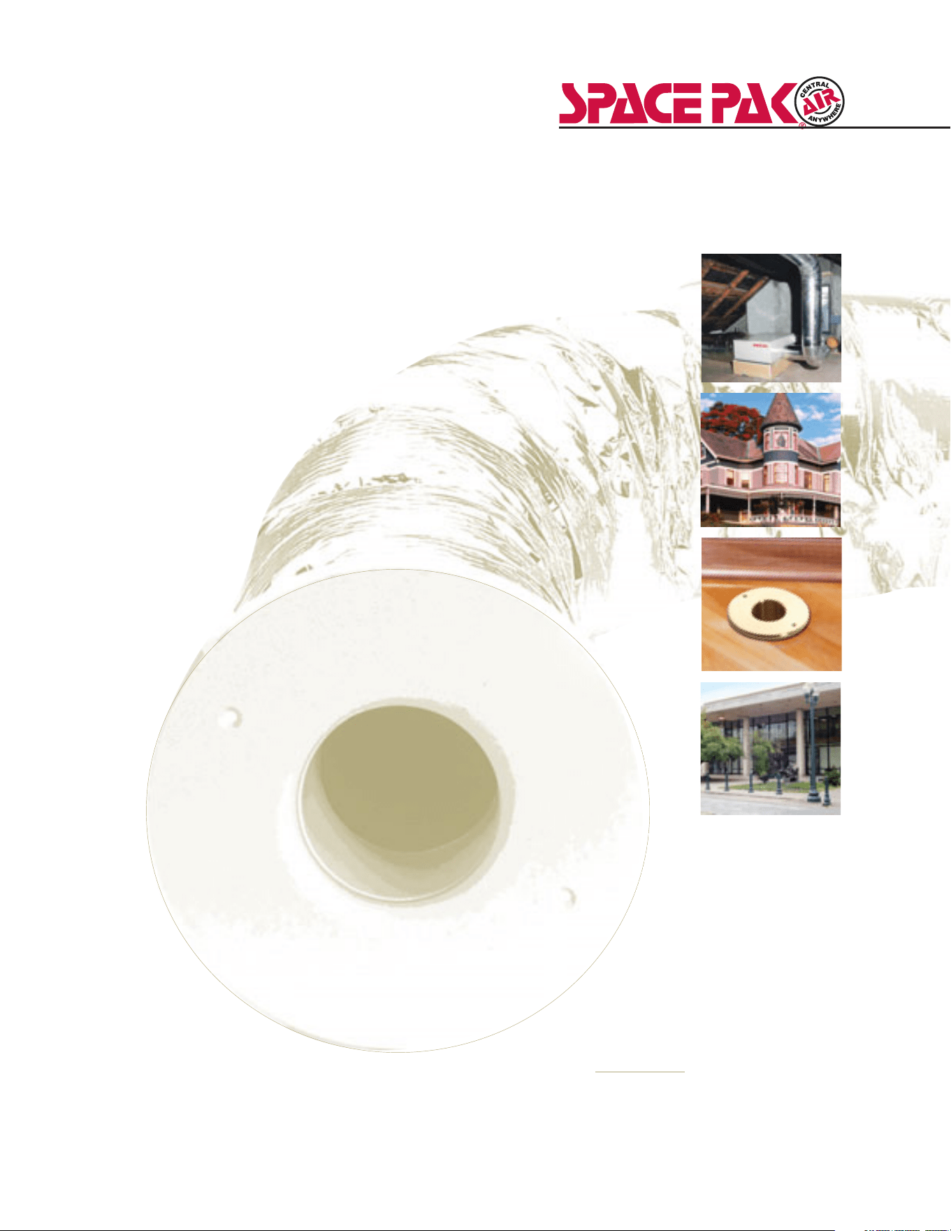
SpacePak is the original,
high-velocity cooling
solution for older homes
not equipped for central
air (heated with hot
water, steam or radiant
electric heat) and new
homes featuring hydronic
heating systems,
including radiant floor
heating. SpacePak’s
successful track record
includes thousands of
residential installations
and opens up profitable
opportunities for
contractors. Ease of
installation and quiet,
efficient operation make
SpacePak the number one
choice of quality-conscious
contractors, homeowners
and building owners.
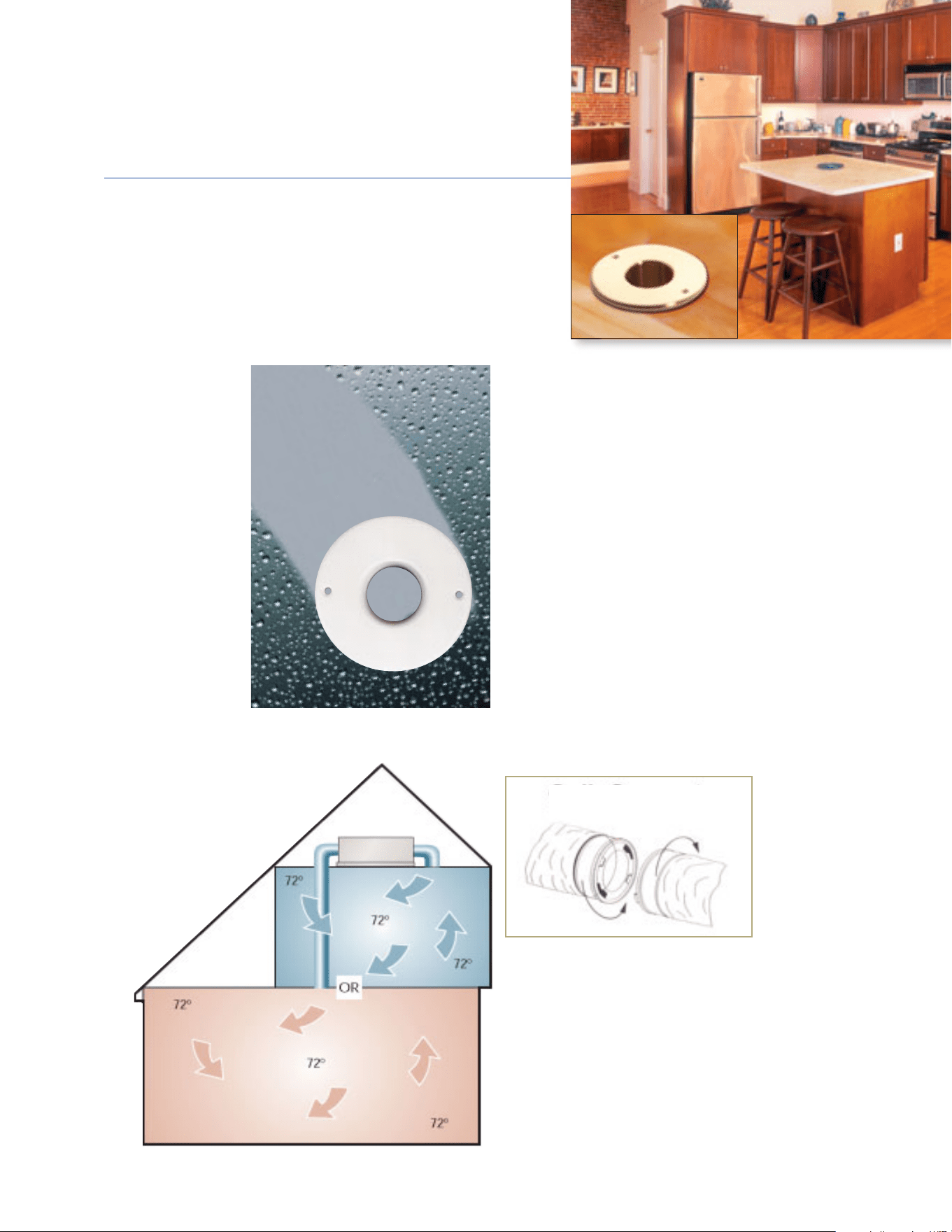
Quiet and comfort gives contractors
a sales edge
SpacePak is ultra quiet
and works through the
principle of aspiration.
Air in the duct is under
5 to 6 times higher
pressure than
conventional systems.
Air exiting the duct
expands and creates
eddy currents that
blend the conditioned
air, providing uniform,
draft-free temperature
from floor to ceiling
and room to room.
And because SpacePak
removes up to 30%
more moisture,
homeowners are kept cool and comfortable
at a higher, more energy efficient
thermostat setting.
The ‘Kwik-Way’ to ensure
proper sizing
Proper sizing is critical to the performance
of the SpacePak system. SpacePak provides
an easy to use, ‘Kwik-Way’ sizing sheet to
help contractors calculate the heat gain
and/or heat loss of a structure to assure
maximum comfort of the occupants.
Kwik-Way sizing includes (1) Equipment
Selection, Job Estimating and System
Design, (2) Room-by-Room Analysis
and (3) System Design Considerations.
Detailed information can be found in the
SpacePak Factory Trained Installer Handbook
and online at www.spacepak.com.
‘Kwik-Connect’ makes
installation a snap
The SpacePak system features unique ‘Kwik-
Connect’ adapters to save time and money
during installation. Simply position the slots
and turn to the lock position to provide a secure,
air-tight seal for flexible duct connections.
u
p
t
o
3
0
%
m
o
r
e
R
e
m
o
v
e
s
m
o
i
s
t
u
r
e
Gentle mixing of air
eliminates drafts and
minimizes temperature
differentials
Removes up to 30% more moisture
for enhanced comfort
KWIK-CONNECT
3
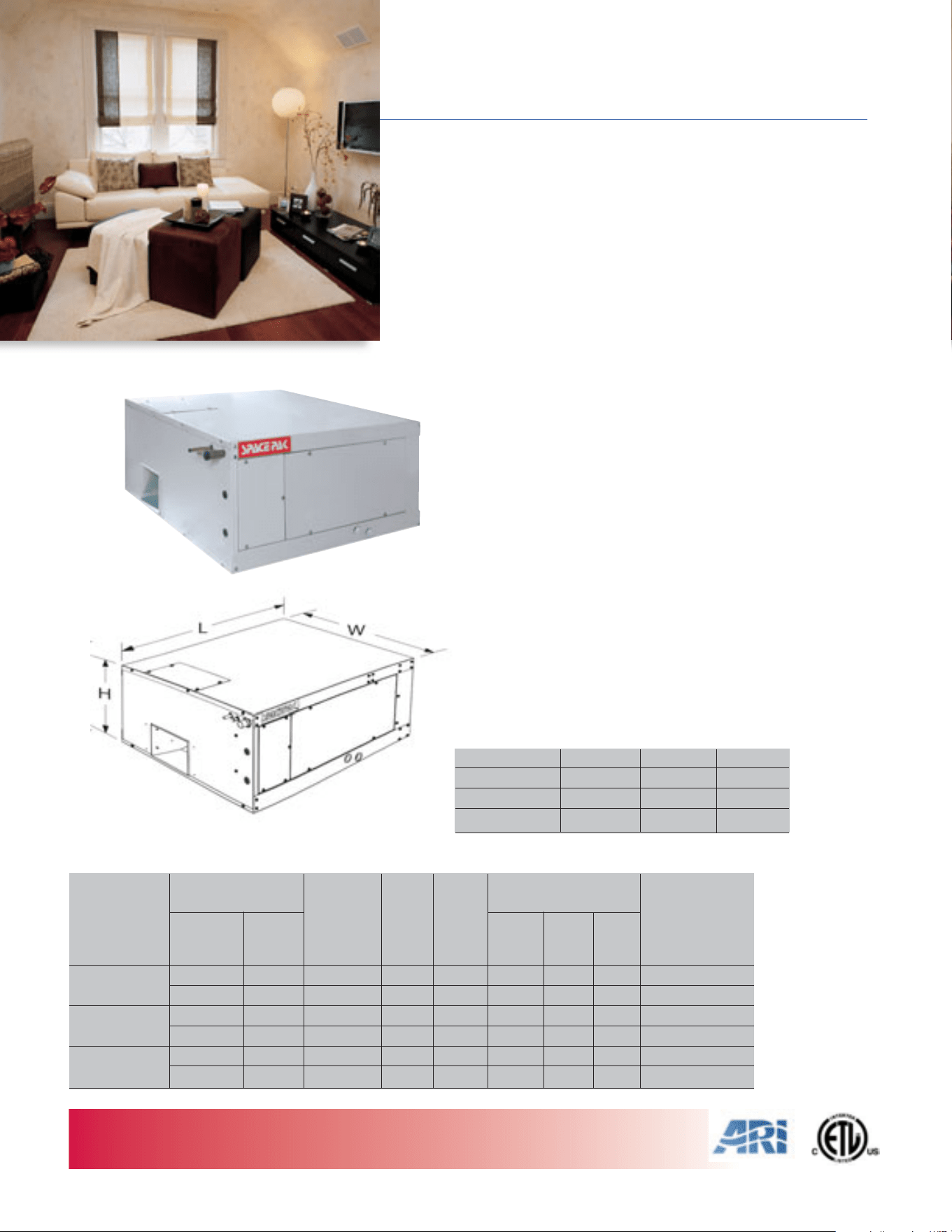
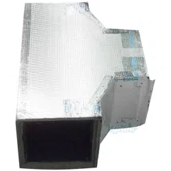
MODEL ESP-HORIZONTAL
CENTRAL AIR CONDITIONING
HEAT PUMP SYSTEM
2 to 5 Tons
One-piece blower unit with DX coil
MODEL Height Width Length
ESP-2430 14-1/8" 24-1/8" 29-3/8"
ESP-3642 14-1/8" 33-1/8" 29-3/8"
ESP-4860 14-1/8" 43-1/8" 29-3/8"
FAN COIL UNIT DIMENSIONS
Standard Fan Coil Features
• Corrosion-resistant cabinet with baked enamel finish
• Fully insulated with 1-1/2 lb. density batt
• Six-row copper tube aluminum fin evaporator coil removes up to
30% more humidity than conventional coil
• Blower motor is factory-balanced for vibration-free operation
• Condensate drain connection in base pan for specially-designed,
factory-supplied condensate drain assembly
• Factory-assembled, pre-wired control center with high and low
voltage terminal blocks, blower relay and low voltage transformer
• Factory-installed anti-frost control and thermal expansion valve
• Standard factory-installed primary drain pan float switch
• Sweat-type suction/liquid line connections
• Meets or exceeds DOE standards for energy efficiency
• Visit www.ari.org to identify compatible condensing units
and view associated performance/efficiency ratings
4
TOTAL COMFORT, WHOLE-HOUSE HEATING and COOLING SYSTEM
For supplemental electric or hydronic heat modules see page 9.
SPECIFICATIONS
Std. CFM
Connections
Recommended
@
Motor F.L. Suction Liquid
Ship
Condensing UnitCool
Wt.
Model Nom. Tons MBH 1.5" W.C. HP Amps Line Line (lbs.) Capacity(MBH)
ESP-2430 2 21.0 550 1/3 1.8 7/8" 3/8" 120 24
2-1/2 24.6 550 1/3 1.8 7/8" 3/8" 120 30
ESP-3642 3 33.4 850 1/2 2.8 7/8" 3/8" 144 36
3-1/2 38.5 850 1/2 2.8 7/8" 3/8" 144 42
ESP-4860 4 45.0 1150 1 3.6 7/8" 3/8" 171 48
5 54.0 1150 1 3.6 7/8" 3/8" 171 60
Nominal System
Capacity
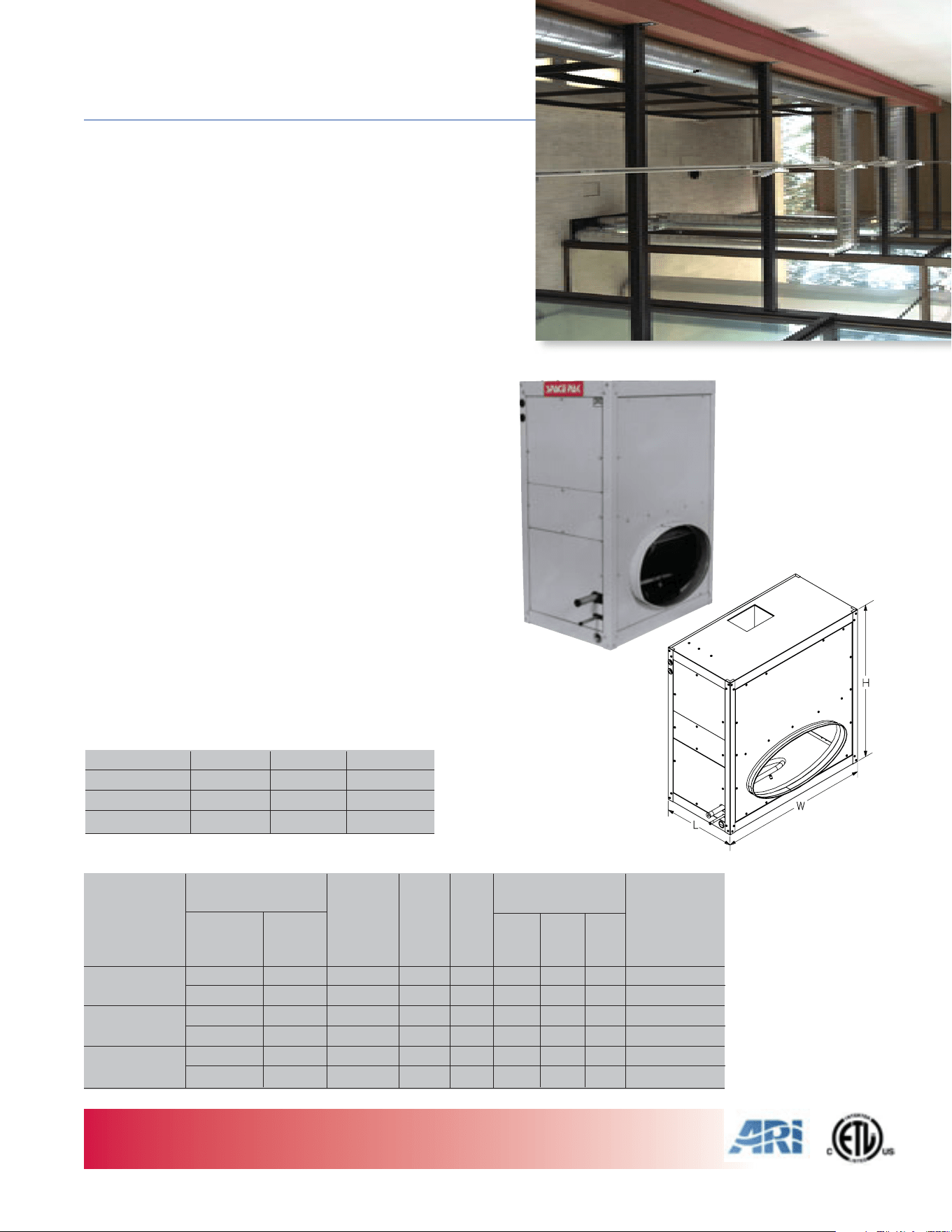
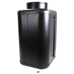
MODEL ESP-VERTICAL
CENTRAL AIR CONDITIONING
HEAT PUMP SYSTEM
2 to 5 Tons
One-piece blower unit with DX coil
Standard Fan Coil Features
• Fully-insulated, corrosion-resistant cabinet with baked enamel
finish, 1-1/2 lb. density batt
• Six-row copper tube aluminum fin evaporator coil removes up to
30% more humidity than conventional coil
• Blower motor is factory-balanced for vibration-free performance
• Condensate drain connection in base pan for specially-designed,
factory-supplied condensate drain assembly
• Factory-assembled, pre-wired control center with high and low
voltage terminal blocks, blower relay and low voltage transformer
• Factory-installed anti-frost control and thermal expansion valve
• Standard factory-installed primary drain pan float switch
• Sweat-type water line connections
• All connections located on same side of unit
• Meets or exceeds DOE standards for energy efficiency
• Visit www.ari.org to identify compatible condensing units and
view associated performance/efficiency ratings
MODEL Height Width Length
ESP-2430V 33" 24" 16-1/8"
ESP-3642V 33" 33" 16-1/8"
ESP-4860V 33" 43" 16-1/8"
FAN COIL UNIT DIMENSIONS
SPECIFICATIONS
5
NOTES: Electrical characteristics 208-230/1/60. For cooling capacity and SEER rating when mated with a specific condensing unit, check the ARI directory at www.ari.org.
TOTAL COMFORT, WHOLE-HOUSE HEATING and COOLING SYSTEM
For supplemental electric or hydronic heat modules see page 9.
Std. CFM
Connections
Recommended
@
Motor F.L. Suction Liquid
Ship
Condensing UnitCool
Wt.
Model Nom. Tons MBH 1.5" W.C. HP Amps Line Line (lbs.) Capacity (MBH)
ESP-2430V 2 23.0 550 1/3 1.8 7/8" 3/8" 98 24
2-1/2 27.6 550 1/3 1.8 7/8" 3/8" 98 30
ESP-3642V 3 35.0 850 1/2 2.8 7/8" 3/8" 120 36
3-1/2 40.0 850 1/2 2.8 7/8" 3/8" 120 42
ESP-4860V 4 48.0 1150 1 3.6 7/8" 3/8" 145 48
5 57.0 1150 1 3.6 7/8" 3/8" 145 60
Nominal System
Capacity
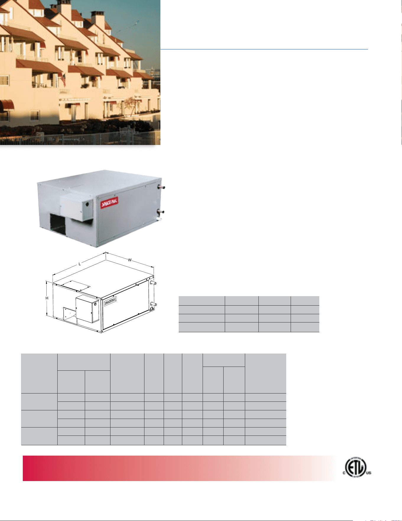
MODEL WCSP
CENTRAL AIR CONDITIONING
HYDRONIC COIL SYSTEM
2 to 5 Tons
One-piece central unit with chilled water coil
Standard Fan Coil Features
• Ideal for commercial/institutional and Geo-Thermal applications
• Can be installed with conventional chiller or boiler unit as long
as capacity and line connections meet SpacePak standards
• Fully insulated blower unit cabinet with baked enamel finish,
1-1/2 lb. density batt
• Six-row copper tube aluminum fin water coil provides efficient
operation
• Blower motor is factory-balanced for vibration-free performance
• Condensate drain connection in base pan for specially-designed,
factory-supplied condensate drain assembly
• Factory-assembled, pre-wired control center with high and low
voltage terminal blocks, blower relay and low voltage transformer
• Standard factory-installed primary drain pan float switch
• Sweat-type water line connections
MODEL Height Width Length
WCSP-2430 14-1/8" 24-1/8" 30"
WCSP-3642 14-1/8" 33-1/8" 30"
WCSP-4860 14-1/8" 43-1/8" 30"
FAN COIL UNIT DIMENSIONS
SPECIFICATIONS
6
Water Water
In Out
Recommended
Std. CFM
@
TOTAL COMFORT, WHOLE-HOUSE HEATING and COOLING SYSTEM
For supplemental hot water coil heat modules see ‘WPAK’ page 9.
Nominal System
Connections
Capacity
Cool Motor F.L. Suction
Chiller Unit
Model Nom. Tons MBH 1.5" W.C. HP Amps Line Line Line Capacity
(MBH)
WCSP-2430 2 21.0 550 1/3 1.8 7/8" 7/8" 7/8" 24
2-1/2 24.6 550 1/3 1.8 7/8" 7/8" 7/8" 30
WCSP-3642 3 33.4 850 1/2 2.8 7/8" 7/8" 7/8" 36
3-1/2 38.5 850 1/2 2.8 7/8" 7/8" 7/8" 42
WCSP-4860 4 45.0 1150 1 3.6 7/8" 7/8" 7/8" 48
5 54.0 1150 1 3.6 7/8" 7/8" 7/8" 60
7
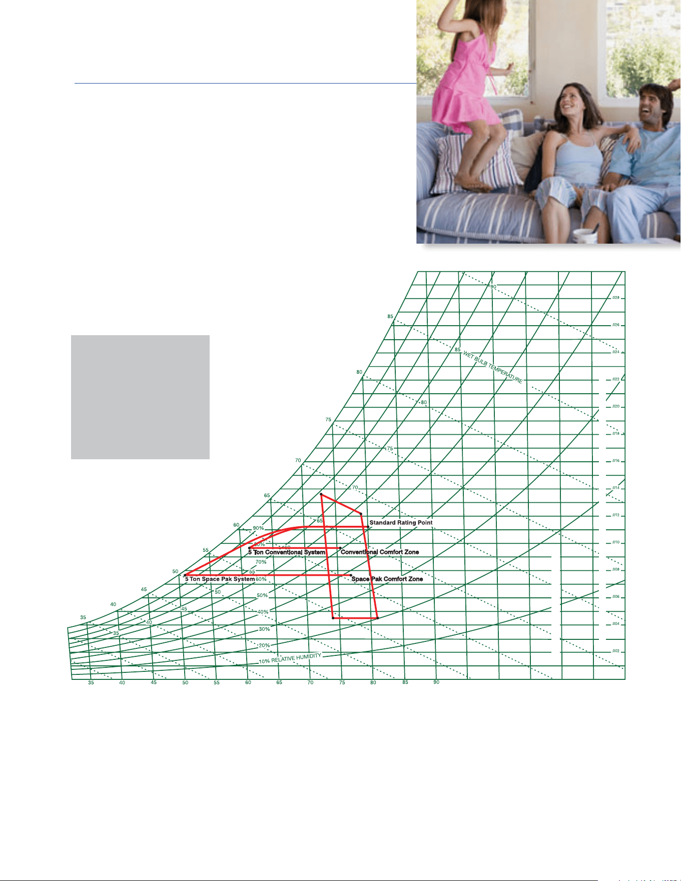
SENSIBLE HEAT RATIOS
HUMIDITY REMOVAL
30% BETTER HUMIDITY
REMOVAL THAN
CONVENTIONAL
AIR CONDITIONING
ASHRAE PSYCHROMETRIC
CHART NO. 1
Normal Temperature
Barometric Pressure
29.921 Inches of Mercury
SEA LEVEL
H
U
M
ID
IT
Y
R
A
T
IO P
O
U
N
D
S
M
O
I
S
T
U
R
E
P
E
R
P
O
U
N
D
D
R
Y
A
IR
DRY BULB TEMPERATURE ºF
95
100
105
110
115
120
NOTE: All temperature measures listed are Fahrenheit.
SpacePak averages 250 CFM per ton cooling versus 400 CFM for conventional systems. SpacePak’s 6-row coil provides a greater
temperature drop of the air passing through the coil, typically 24˚ to 28˚F. Specially designed blower pressurizes the duct system 5 to 6
times higher than conventional duct systems. Air exiting into the room is traveling at high velocity, approximately 2000 Ft./Sec. creating
floor to ceiling circulation of the air in the room. The air under pressure in the duct system expands as it is released into the room.
More moisture is taken out of the air because it is in contact with the coil longer, driving it to a lower dew point temperature.
Drier air increases the body’s ability to cool itself by perspiration evaporating off the skin. The SpacePak system, by lowering the RH,
can run at higher temperature settings. By setting the temperature to 72˚ instead of 70˚, customers can save 15% on their annual
cooling energy cost – without sacrificing comfort.
Sensible Heat Ratios
Conventional = .724
SpacePak = .642
11.5% Lower Sensible Heat Ratio!
Moisture Removal (Dehumidification)
Conventional 14.3 lb/hr
SpacePak 18.6 lb/hr
30% Greater Moisture Removal!
77 Degrees Feels Like 75 Degrees!
© 1992 AMERICAN SOCIETY OF HEATING,
REFRIGERATING AND AIR CONDITIONING ENGINEERS, INC.
SpacePak removes
humidity and
delivers evenly
distributed cool air
from room to room to
ensure superior
comfort
8
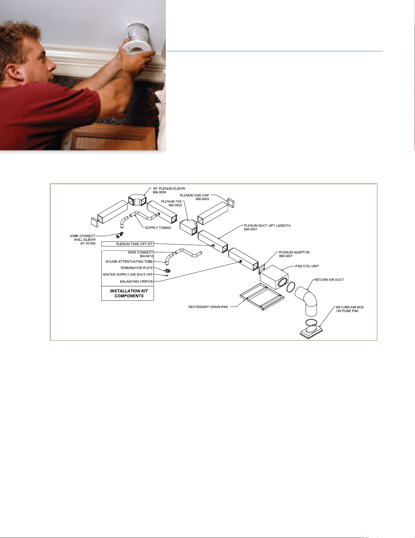
The SpacePak system has been designed to reduce installation time and cost for
installing contractors. Small diameter, flexible tubing weaves around construction
obstacles and eliminates the need for large, cumbersome ductwork and major
structural renovations. Fittings simply snap securely into place with no tools required.
The typical installation diagram and guidelines listed below provide a quick reference
to ensure successful installation and operation of the system. More detailed and comprehensive information is available in our
Factory Trained Installer Handbook and on our website at www.spacepak.com.
Outlets – The most important rule of thumb when installing
a SpacePak system is having the proper number of outlets.
Six (6) to Seven (7) outlets per ton are recommended for
optimal 35-40 CFM airflow from each outlet under normal
conditions to maximize aspiration.
Outlet Placement –
Outlets should be placed in the room where
they will create the least disturbance (floors, ceilings, walls)
and not infringe upon inhabitants with turbulent air. Traffic
patterns, drapes and bed placement are all factors to consider.
Supply Duct–Ideally, all runs should be as equal in length as
possible. Keep the 2" duct length between 9 ft. and 30 ft. for
best performance. The longer the run, the lower the CFM
capacity. See performance chart in IOM.
Main Trunk/Plenum – Maximize use of the main trunkline in
order to minimize the lengths of 2" duct. It will allow for an
easier installation and better performing, balanced system
if 2" duct lines are minimized.
60/40 Rule – Always try to use a full flow “T” in larger, 4-5
ton systems. Never exceed a 60/40 split of outlets off the
main trunkline in order to maintain evenly distributed
airflow. A perfect 50/50 split is best.
Locating Take-Offs – Distribute takeoffs as evenly as possible
along the main trunkline – no closer than 6" away from one
another. This will assure better balanced airflow.
Sound Attenuators – The last 3 ft. of every run should use
a fully-fabricated SpacePak sound attenuator to reduce
outlet air sound.
Return Air Duct – Minimize potential fan noise and maximize
performance of this acoustically lined duct by incorporating a
90-degree bend between the air handler and return grille.
TYPICAL INSTALLATION
EASY TO INSTALL SYSTEM
9
RETURN AIR
Outdoors
SpacePak
System
2’ (610 mm) min.
recommended
2’ (610 mm) min.
recommended
HRV/ERV by others
VENTILATION AIR
POSSIBILITIES
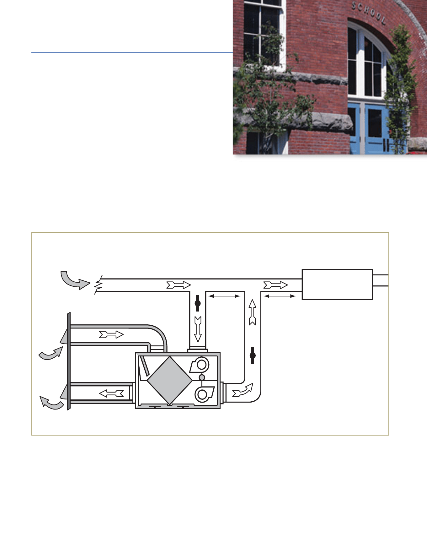
By adding a hot water or electric heating coil, SpacePak becomes a year
round cooling and heating ventilation system with continuous blower
operation any time a building is occupied and needs to be ventilated.
This configuration makes SpacePak ideal for Makeup Air applications
commonly required in office complexes, libraries, schools, apartment
buildings and other commercial/institutional buildings.
TYPICAL HRV/ERV SPACEPAK SYSTEM INSTALLATION
NOTES:
1. Furnace/AC Blower is required to operate when ventilation from HRV/ERV is required.
2. A minimum separation of 24-inches (610 mm) is required between the two direct connections.
3. The exhaust air connection should be upstream of the supply air connection to prevent exhausting any fresh air.
4. Weatherhood arrangement is for drawing purposes only. Six feet (2 m) minimum separation required. Eighteen inches (460 mm) above grade minimum.
5. Due to the differences in pressure between the HRV/ERV and the equipment it is being connected to, the HRV/ERV’s airflow must be confirmed on site
using the balancing procedure found in the HRV/ERV manufacturers manual.
The benefits for commercial applications include:
• Compact design increases billable space
• Energy recovery compatibility
• Reduces overall cooling load
• Satisfies ASHRAE 62.1 Ventilation Requirements
• Lowers labor and equipment costs
• Enhances and preserves architectural integrity
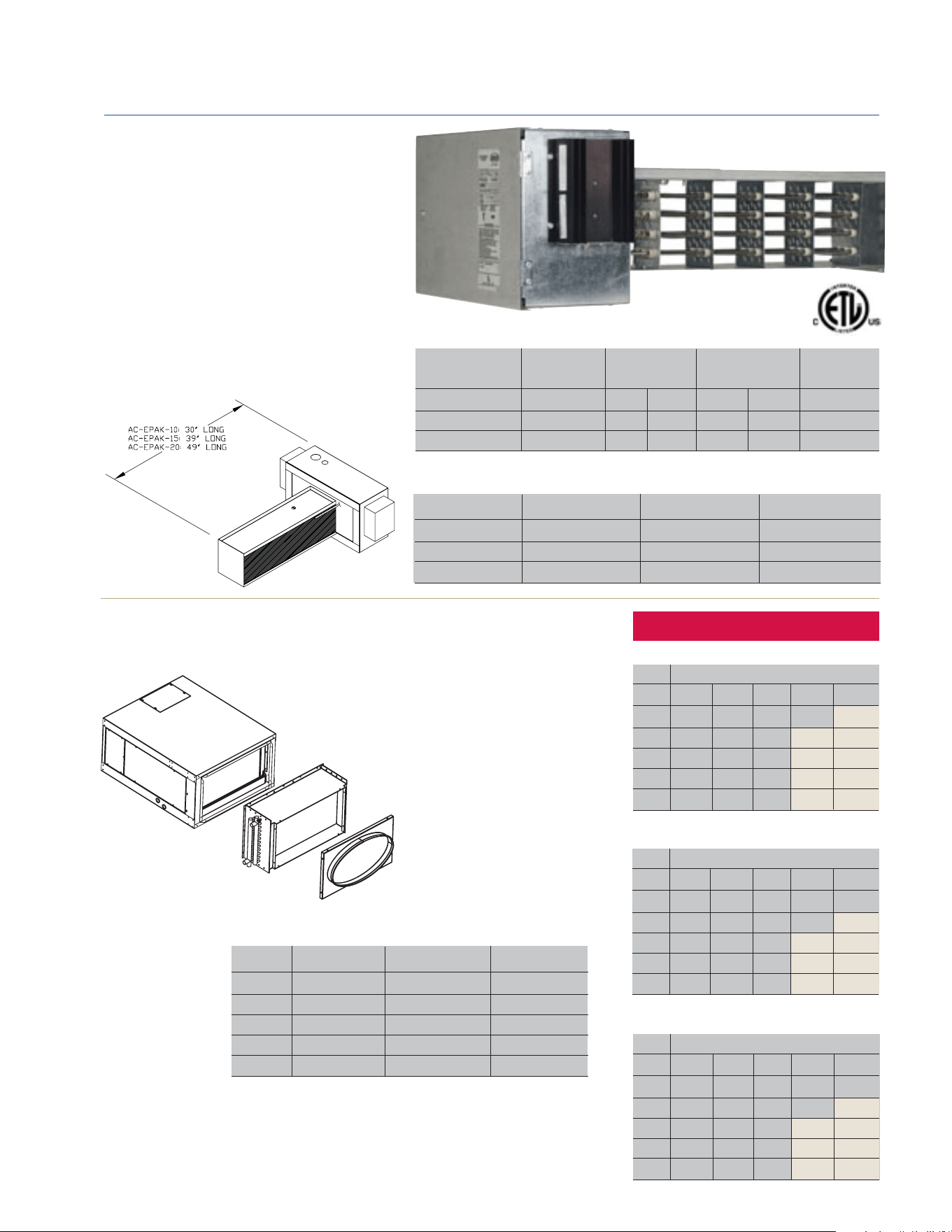
ELECTRI PAK
Integral Electric Heat Module
for DX Fan Coil Units
Designed to provide a heating option for SpacePak
systems. Easy to install in both new and existing
systems and fit directly inside horizontal fan coil units.
Equipped with an internal modulating feature, heat
discharge temperatures are sensed and can be
controlled regardless of load condition. Heater design
eliminates the need for external regulating devices
such as a multi-stage (W3) and/or outdoor thermostat.
Entering Water Temperature (F)
GPM 120 140 160 180 200
2 31.7 46.2 61.2 75.1 89.0
4 45.6 64.2 83.0 102.0 120.9
6 50.6 71.2 92.0 112.9 133.8
8 53.1 74.7 96.4 118.2 140.1
10 54.6 76.7 98.9 121.2 143.6
MODEL AC-WPAK-120 for ESP 4860
WPAK Hydronic heating coil is designed for use with
SpacePak fan coil units. Easily Mount to the inlet of
the fan coil unit. Use the chart below to match
the proper hydronic coil with the SpacePak
Fan Coil Unit
Entering Water Temperature (F)
GPM 120 140 160 180 200
2 28.8 39.2 51.6 63.4 75.2
4 36.0 50.8 65.7 80.8 95.8
6 39.0 54.9 70.9 87.0 103.1
8 40.4 56.8 73.3 89.9 106.5
10 41.2 57.9 74.7 91.5 108.4
MODEL AC-WPAK-90 for ESP 3642
Entering Water Temperature (F)
GPM 120 140 160 180 200
2 20.5 30.0 39.1 48.1 57.2
4 25.2 35.6 46.1 56.6 67.1
6 26.6 37.4 48.3 59.2 70.2
8 27.2 38.2 49.3 60.4 71.6
10 27.5 38.7 49.9 61.1 72.3
MODEL AC-WPAK-60 for ESP 2430
Model Nominal Air Flow Minimum Air Flow Model
AC-EPAK-10 550 440 ESP-2430
AC-EPAK-15 850 680 ESP-3642
AC-EPAK-20 1150 920 ESP-4960
Electric Heat Heat Output 208/1/60 230/1/60 Fan Coil Unit
Module Model @ 240V FLA MCA FLA MCA Model
AC-EPAK-10 10kW 48 60 43 54 ESP-2430
AC-EPAK-15 15kW 72 90 65 52 ESP-3642
AC-EPAK-20 20kW 96 120 87 109 ESP-4960
HEATER COMPATIBILITY/CIRCUIT SIZE
MINIMUM AIR FLOW REQUIREMENTS (CFM)
HEATING OPTIONS
CAUTION:
Areas shaded in tan can exceed
160°F leaving air temperature.
To prevent injury or damage, do not
install floor outlets when the system
is operating in this range.
10
HEATING CAPACITY MBH
MODEL WPAK HYDRONIC COIL
At 850 CFM and 70°F Entering Air Temperature*
At 550 CFM and 70°F Entering Air Temperature*
At 1150 CFM and 70°F Entering Air Temperature*
*To calculate Leaving Air Temperature (LAT)
use the following formula:
LAT=(BTUH/(1.08XCFM)) +70
GPM AC-WPAK-60 AC-WPAK-90 AC-WPAK-120
2 0.4 0.4 0.5
4 1.4 1.6 1.7
6 3.0 3.3 3.7
8 5.2 5.7 6.3
10 7.9 8.7 9.6
Water Pressure Drop (in feet @ 180°)
11
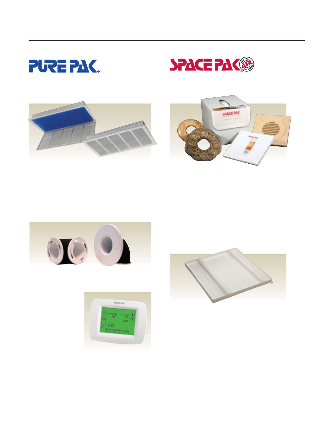
OPTIONAL ACCESSORIES
RECESSED AIR CLEANER
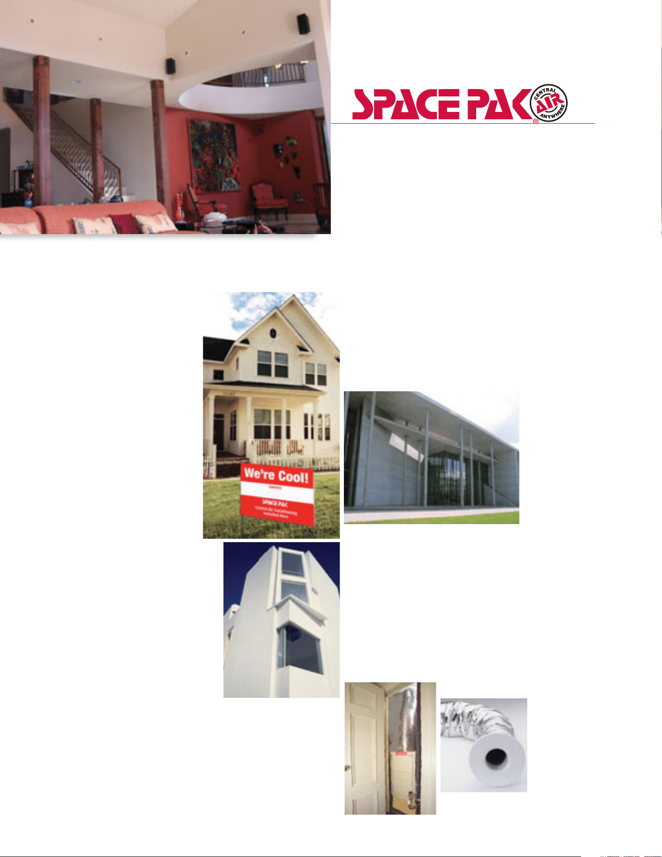
ARCHITECTURAL OUTLETS
Removes dangerous airborne particles
other cleaning systems miss
The PurePak system is the key to cleaner, healthier air.
It turns the SpacePak system into a whole-house air
cleaner quickly and economically. PurePak is controlled
by the thermostat fan setting and runs on safe, 24-volt
power. It is an easy-to-install, value-added option that
your customers will appreciate.
THERMOSTAT
Blend with any décor
SpacePak offers the widest variety of Architectural
Outlets and Covers to blend with any décor. From
finished aluminum and brass to Victorian elegance
to natural wood grain. An Architectural Outlet Kit is
available that contains a complete selector guide
booklet of each item, as well as representative
samples.
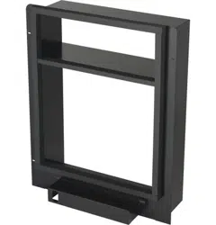
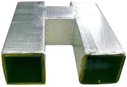
• Durable polyethylene will not rust
• Resistant to mold growth
• UL recognized material
• Integral, multi-function support channels
• Supports unit when suspended with threaded rod
• Fits through hole cut-out used for return air box
• Threaded
3
/
4
" drain connection
• Meets International Mechanical Code 307.2.3
Features
• Large, back-lit display
shows the current and set
temperature and time
• Effortless set-up with
menu-driven programming
• Smart, sophisticated, ergonomic design
• Touch screen interaction
• Real-time clock keeps time during power failures
• “Saving Changes” notification lets you know when
changes have been saved
BASE PAK SECONDARY DRAIN
PANS FOR HORIZONTAL FAN
COIL UNITS
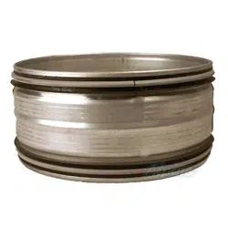
KWIK CONNECT WALL ELBOW
Kwik Connect wall elbows simply snap into place for fast,
easy installation.
260 North Elm Street, Westfield, MA 01085, Tel. 800-465-8558 • Canada: 7555 Tranmere Drive, Mississauga, Ontario, L5S IL4, Canada, Tel. 905-672-2991
www.spacepak.com
SCB-1
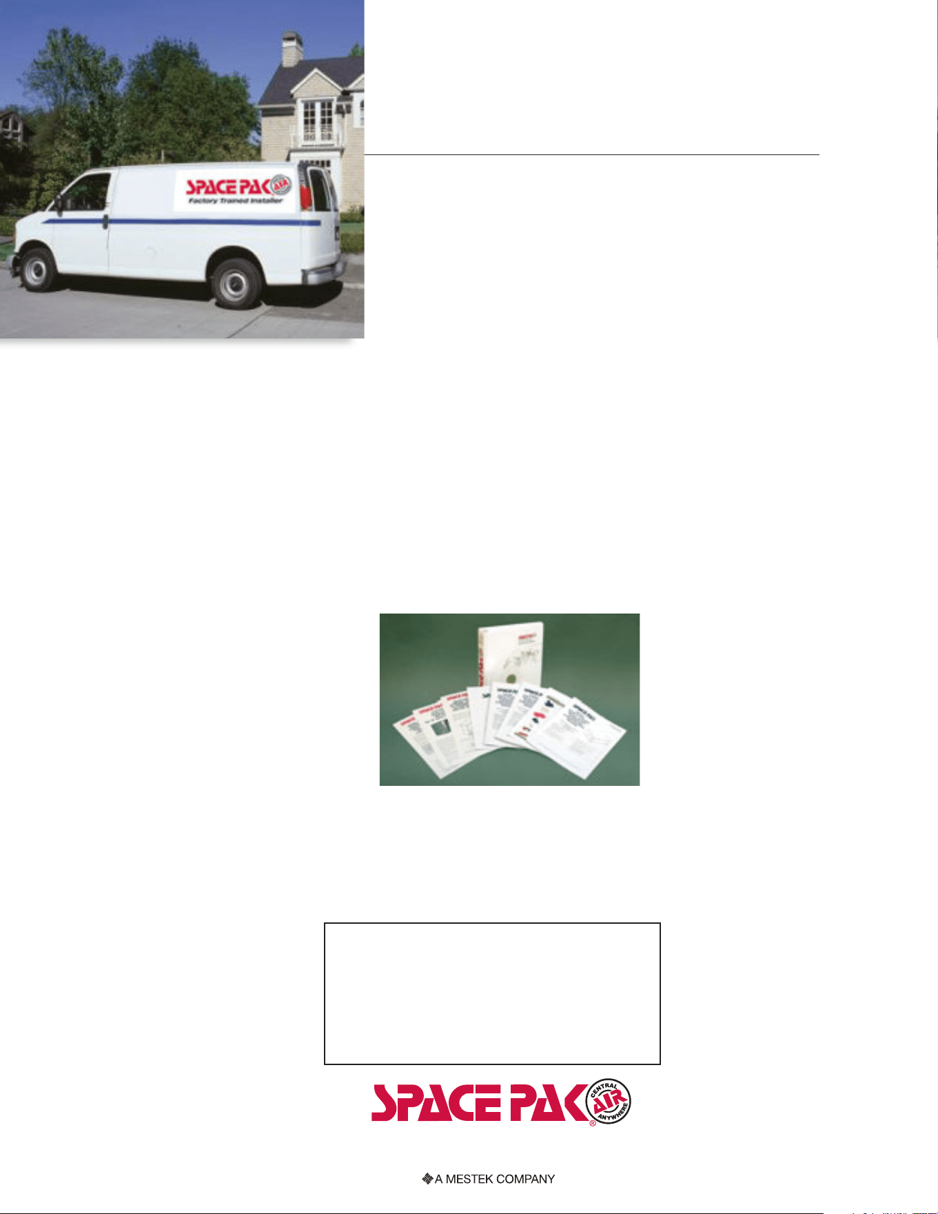
TRAINING
& SALES
SUPPORT
The SpacePak Factory Trained Installer
Handbook is a resource of knowledge
for every aspect of a SpacePak system,
featuring product information, specifi-
cations and engineering drawings.
SpacePak offers comprehensive
installation training and effective sales
support and promotional tools for
installing contractors. As a Factory
Trained Installer you will save time
and money on every job and receive an
Extended 5-Year Warranty on installed
systems. SpacePak training classes are
held at the Reed Institute, located in
Westfield, MA, and at various locations
throughout the country.
Pre-printed sales support materials
include homeowner brochures,
yard signs, door hangers, truck decals,
homeowner direct mail pamphlets,
customizable print advertisements
and more. Call a local sales representative
at 800-465-8558 for more information
about SpacePak training and sales support.