SECTION 1: INTRODUCTION ................................ 1
SmartSeal Metal Duct .......................................... 2
SECTION 2: INSTALLATION .................................. 2
Steps 1 and 2: ........................................................... 2
SECTION 3: ATTACHING AIR PLENUM
ADAPTOR (AL-SM9-PA) ........................................... 2
Step 4 Thru 7: ......................................................... 3
Step 8: Installing Air Distibution Components
(Plenum Duct and Plenum Take-Offs) .................... 3-4
IN UNITED STATES: 260 NORTH ELM ST. WESTFIELD, MA 01085 800-465-8558/FAX (413) 564-5815
IN CANADA: 7555 TRANMERE DRIVE, MISSISSAUGA, ONTARIO, L5S 1L4 (905) 672-2991/FAX (905) 672-2883
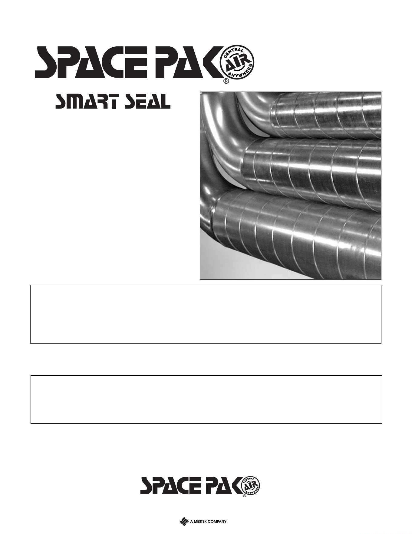
GASKETED
SPIRAL
METAL DUCT
INSTALLATION
MANUAL
SMSG2-311
W30-WG0193-01
3/11
SECTION 1: INTRODUCTION
The following terms are used throughout this
manual to bring attention to the presence of potential
hazards or to important information concerning the
product:
NOTICE: Used to notify of special instructions on
installation, operation or maintenance which are
important to equipment but not related to personal
injury hazards.
2
STEPS 1 AND 2: REFER TO FAN COIL UNIT INSTALLATION MANUAL
STEP 3: ATTACHING SUPPLY AIR PLENUM ADAPTOR (AC-SM9-PA)
NOTICE: If unit is to be located in the attic and installed through ceil-
ing joists, attach supply air plenum adaptor in attic.
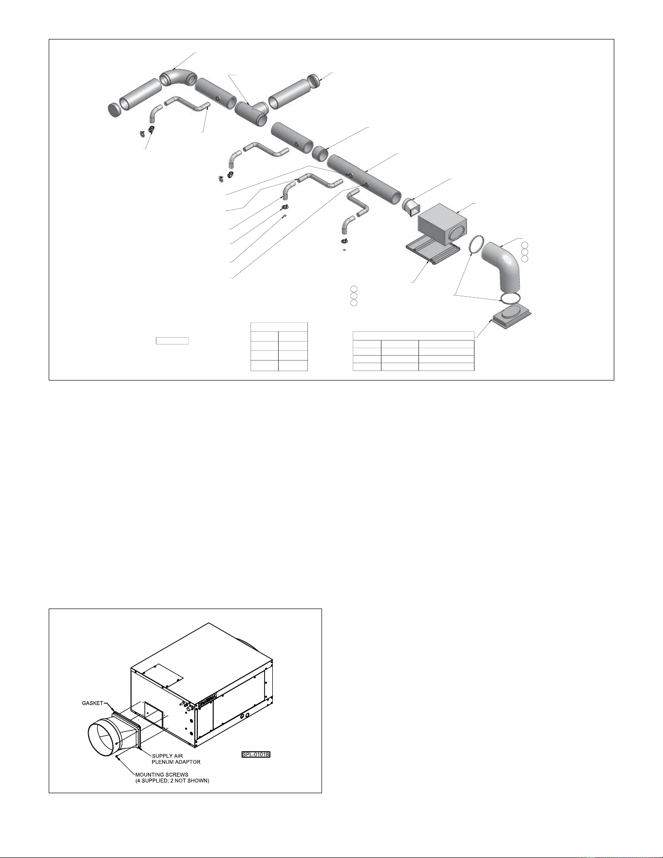
A. HORIZONTAL DISCHARGE: Refer to Figure 2.8.
Remove backing from gasket and mate it to fan coil unit so blower
opening is centered in plenum adaptor opening and adaptor is
flush with bottom of unit. Place plenum adaptor over discharge
opening and align with the (4) unit holes surrounding the blower
opening. Secure adaptor to unit with sheet metal screws provided.
FIGURE 2.8
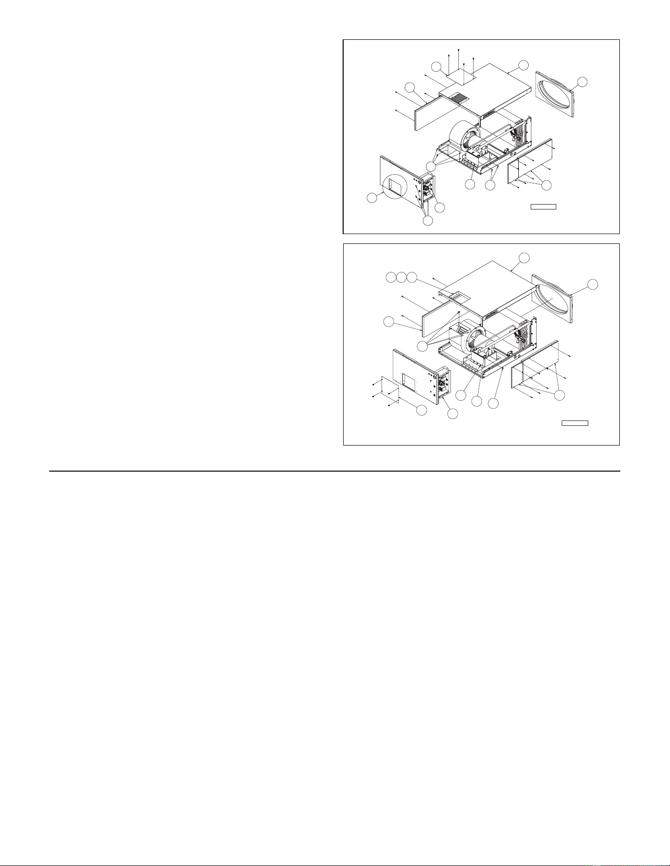
B. TO CONVERT TO VERTICAL DISCHARGE:
Refer to Figure 2.9A & 2.9B
Tools required: 1/4", 5/16", 3/8", 7/16" box wrenches and nut
drivers, 5/32" Allen wrench, utility knife & Malco S-3 offset
hand seamer (3" duct-bill pliers).
Field supplied: latex caulk, UL classified duct liner adhesive (or
equivalent).
NOTICE: An Electric Heat Module cannot be installed after unit
has been field converted to vertical supply air discharge (due to
resulting blower housing obstruction).
Refer to Figure 2.9A for Steps 2 to 8a.
1. Place unit horizontally on a flat raised surface.
2. Remove all side access panels, return air panel and
cover plate from top panel.
3. Remove top panel by removing top/center screw from
electric control box and panel screws.
4. Remove (4) screws securing front panel flange to blower
housing.
5. Remove sealant around discharge opening.
6. Remove (3) remaining screws from electrical control box.
Set box aside.
7. Remove (2) screws attaching blower housing to motor
support channel flange.
8a. Remove (6) screws attaching motor mounting base to
motor support channel.
Refer to Figure 2.9B for Steps 8b to 18.
SECTION 2: INSTALLATION
SPL-0130B
Legend
Item No. Capacity
2 2430
3 3642
4 4860
90° Plenum Elbow
AC-SM9-EL90
Fan Coil Unit
(See Legend)
Return Air Duct
2 BM-6808-10
3 BM-6809-10
4 BM-6839-10
Plenum Tee
AC-SM9-T
Plenum End Cap
AC-SM9-EC
Kwik Connect
Wall Elbow
AC-KCWE
Supply Tubing
AC-ST6-100
Secondary Drain Pan
2 ACS-BASE-2
3 ACS-BASE-3
4 ACS-BASE-5
Return Air Box Assembly
ITEM NO FILTER AIR CLEANER
2
BM-9149
AC-RBC-2
3
AC-RBF-3 AC-RBC-3
4
BM-9169
AC-RBC-4
Plenum Adaptor
AC-SM9-PA
Plenum Duct (6FT Length)
AC-SM9-6
Round Plenum Take-Off
AC-TORD
Kwik Connect
BM-6818
Sound Attenuating Tube
BM-6926
Terminator Plate
BM-6845
Winter Supply Air Shut-Off
BM-6819
Balancing Orifice
27-6123 (15%)
27-6124 (35%)
27-6125 (50%)
Duct Strap
Coupling
AC-SM9-C
SmartSeal duct components shown above without factory supplied R8.0 insulated jacketry.
3
8b. Shift motor mounting base (and blower housing) back
toward coil to second set of mounting lugs on motor
support channel. Rotate blower housing up 90°.
Reattach base with screws.
9. Cut insulation from discharge air location on top panel (opening
dimensions shown in Figure 2.3 of unit manual). Insert cut piece
into opening. Apply adhesive per manufacturer's instructions.
Attach cover plate to front of unit.
10. Bend both flanges 90° into cabinet using 3" duct-bill
pliers. Pliers should engage full jaw depth (1-1/4") and
be centered on flange.
11. Insert blower housing into top panel. Reattach panel to unit.
12. Align hole in blower housing with lower slot in motor
support channel flange. Attach housing to flange with
(1) previously removed screw.
13. Align (4) holes in top panel flange with holes in blower
housing. Attach with removed screws.
14. Assure blower wheel is centered in inlet and discharge of
blower housing. If required, adjust by loosening (4) bolts
securing motor. Shift motor and refasten. For blower
wheel adjustments, loosen set screw (not shown), shift
wheel and refasten.
15. Apply latex caulk to seal between blower housing
and top panel.
16. Reinstall electrical control box.
17. Plenum adaptor can be installed so offset faces either
end of fan coil unit. Remove backing from gasket and
mate it to fan coil unit so blower opening is centered in
plenum adaptor opening. Place plenum adaptor over
discharge opening and align with the (4) unit holes
surrounding the blower opening. Secure adaptor to
unit with sheet metal screws provided.
NOTICE: Check that all inside cabinet surfaces are covered
with insulation, add insulation if required. An uninsulated
panel will “sweat” and condensate will form on the cabinet.
18. Replace all panels and screws.
FIGURE 2.9A
STEPS 4 THRU 7: REFER TO FAN COIL UNIT INSTALLATION MANUAL
STEP 8: INSTALLING AIR DISTRIBUTION COMPONENTS (Plenum Duct and
Plenum Take-offs)
All plenum duct and supply tubing runs as well as room
terminator locations must be in accordance with air
distribution system requirements listed in Section 1 of fan
coil unit installation, operation and maintenance manuals.
Where taping is required, use UL 181A approved tape.
Tools Required: SpacePak Pliers (PTO Clip Spreader), saw
(hand or reciprocating), drill fitted with 2-1/8" arbored hole saw,
1/4" nut driver and utility knife.
Plenum Duct Installation
NOTICE: SmartSeal duct fittings are made to fit tight, assur-
ing a proper seal. Care should be taken when handling
these fittings as damage could result in an improper fit and
a difficult installation process.
All tees, elbows and branch runs must be a minimum of 24"
from the fan coil unit or any other tee, elbow or branch run.
Keep all tees and elbows to a minimum to keep system pres-
sure drop on larger layouts to a minimum. SmartSeal spiral
metal duct comes in 6-foot lengths and may be cut to length.
SmartSeal spiral metal duct can be suspended using vinyl
duct strapping or plumber’s strap. Duct should be supported
every 3 feet with a minimum of two supports per 6 foot length.
Begin installing plenum duct by sliding insulation and metalized
jacket back several inches to expose end of first straight duct
length (14" min. length). Place the straight duct length level
with and around the hemmed edge of the plenum adaptor.
Apply pressure and the straight duct length will slip into place,
stopping at the bead/pipe stop (see Figure 2.10A). Starting
at the largest radial gap between fitting and duct, use (3)
self-tapping sheet metal screws, placed 1/2" from the bead/pipe
stop and spaced evenly around the circumference of the duct
connection (see Figure 2.10B). The gasket and fittings are
designed to allow adequate room to secure the screws per
SMACNA standards. Carefully seal any holes left by
measurements, removed screws, etc.
[Suggested location for Figures 2.10A and 2.10B]
SPL-0074-B
9
16
8b
14
12
18
18
11
13
18
1015
17
SPL-0073-B
2
4
2
3
2
2
8a
7
3
6
5
SECTION 3: ATTACHING AIR PLENUM ADAPTOR
FIGURE 2.9B
4
Cover plenum adaptor with extra insulation wrap included with
straight plenum duct section. Insulation wrap is to be flush
against the unit and secured with UL 181A tape. Reposition duct
insulation and jacket to completely cover duct connection. Seal
jacket seams with UL 181A tape.
To add another length of straight duct, a coupling is required.
Slide insulation and jacketry of the previously installed straight
duct length back several inches, place the coupling level with
and inside the straight duct, and apply pressure until coupling
slips into place, stopping at the bead/pipe stop (see Figure
2.10A). Use (3) self-tapping sheet metal screws, placed 1/2"
from the bead/pipe stop and spaced evenly around the circum-
ference of the duct connection (see Figure 2.10B). Repeat
when connecting the additional length of straight duct. Cover
all connections/couplings with insulation and jacket, and seal
jacket seam with UL 181A tape.
If adding a fitting such as an elbow or tee to straight duct
lengths, a coupling is not required as the fittings come with the
appropriate gasketing installed for a proper seal when mated
with straight duct length. All fittings are manufactured to slip fit
into SmartSeal spiral duct.
Continue adding plenum lengths and other fittings as needed.
Extra insulation and jacketry is provided with the straight duct
lengths and should be used to cover all connected fittings.
Seal all jacket seams with UL 181A tape.
NOTICE: Straight plenum duct sections can be cut to length.
However, be sure to cut duct straight and remove any
resulting burrs. Failure to do so may result in an improper
seal and system failure.
Installation of end caps (at the end of all plenum runs) should
be completed after all plenum take-offs have been installed.
The duct shavings produced with plenum take-off installation
will be blown into the space to be conditioned if sealed into
duct system.
FIGURE 2.10A
Plenum Take-off Installation
Mark locations for take-offs on plenum duct. All take-off locations
must be a minimum of 18" from any plenum tee, plenum elbow or
the fan coil unit. SpacePak recommends take-offs be placed 12"
apart and that any (2) not be installed directly across from each
other (on opposite sides of the duct).
At marked location cut 2-1/8" diameter hole with hole saw.
Begin in reverse to cut through jacket sleeve and insulation
and stop when hole saw teeth contacts duct. Switch drill to
forward and continue to cut through duct. Remove any loose
duct shavings around hole.
With utility knife, make (4) 2" cuts into jacket and insulation
around hole (90° apart). Move insulation away from hole so the
4" diameter take-off gasket can be applied completely to duct
surface.
Remove backing from take-off gasket and press it on duct
location so as not to cover the hole.
NOTICE: Gasket must be installed to seal plenum take-off
to prevent air leakage.
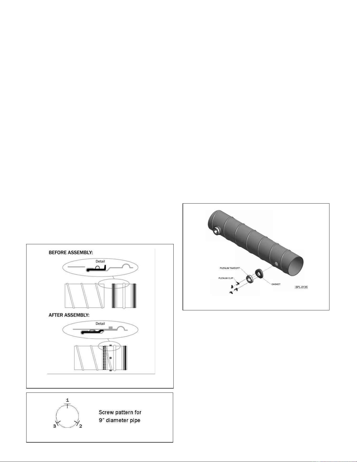
Seat take-off in hole so the curvature matches that of the duct
(see Figure 2.11 - duct shown without insulation and jacket).
Insert (1) plenum clip (green) into a slot opening, then slide
down. Apply enough pressure to take-off so clip grabs inside of
duct. Repeat the procedure with another clip opposite the first
(180°). Using SpacePak pliers secure both clips so they “click”
flush with interior of duct. Complete by inserting (2) more
plenum clips in remaining slots and install as above.
NOTICE: All four clips must be installed to assure air tight
fitting between plenum take-off and plenum.
The insulation and jacket around installed take-off will be
repositioned when attaching supply tubing/kwik-connect
assembly covered in unit’s installation, operation and mainte-
nance manual (Section 2).
After all required plenum take-offs have been installed, clear
interior duct system of loose shavings. Starting the fan coil unit,
prior to assembly of end caps, will clear the system.
Install plenum end cap at the end of each run. Connect end
cap to plenum duct by following procedure described in Plenum
Duct Installation for other plenum fittings. Tape jacket seams
with UL 181A approved tape.
Installation instructions for room terminators, sound attenuating
tubing and supply tubing are provided in installation manual
supplied with fan coil unit (Section 2).
FIGURE 2.11: TAKE-OFF INSTALLATION
FIGURE 2.10B
.
.