1. SAFETY
9 Follow workshop Health & Safety rules, regulations and conditions when using the grease gun.
WARNING! Disconnect from air supply before changing accessories or servicing.
9 Maintain the gun in good condition and replace any damaged or worn parts. Use genuine parts only. Unauthorised parts
may be dangerous and will invalidate the warranty.
WARNING! Check that the correct air pressure is maintained and not exceeded.
9 Keep air hose away from heat, oil and sharp edges. Check hose for wear before each use and ensure that all connections are secure.
9 Wear approved safety gloves and eye and ear protection.
9 Keep gun clean and in good working order for best and safest performance.
9 Keep children and unauthorised persons away from the work area.
8 DO NOT use the gun for a task it is not designed to perform.
WARNING! DO NOT use gun if damaged or thought to be faulty. Contact your local service agent.
WARNING! Grease is delivered at high pressure. DO NOT point the grease nozzle at yourself or others.
WARNING! Excess grease, if left on oors, tools, or equipment, can create surfaces that become slippery.
8 DO NOT operate the trigger until the nozzle is firmly attached to the receiving grease fitting.
8 DO NOT drop, throw, or abuse, the gun.
8 DO NOT carry the gun by the air hose, or yank the hose from the air supply.
8 DO NOT operate gun if you are tired or under the influence of alcohol, drugs or intoxicating medication.
8 DO NOT direct air from the air hose at yourself or others.
9 When not in use, disconnect from air supply and store in a safe, dry, childproof location.
9 Disconnect the Compressed Air line supply before servicing the Gun.
2. INTRODUCTION
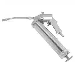
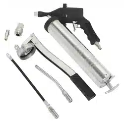
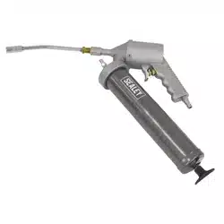
Aluminium die cast head with internal bore precision honed for rapid action. Ideal for use in factory maintenance, vehicle servicing and agricultural
applications. Complete with rigid 150mm steel extension with 4 jaw professional coupler. Delivers a pressure of up to 4800psi with an air operating
range of 40-120psi. Four filling options of cartridge, filling pump,suction and bulk fill. Air Inlet threaded 1/4”(F). Supplied with a male quick coupler
fitting.
3. SPECIFICATION
AIR OPERATED PISTOL GRIP GREASE GUN
MODEL NO: SA40.V2
Thank you for purchasing a Sealey product. Manufactured to a high standard, this product will, if used according to these
instructions, and properly maintained, give you years of trouble free performance.
IMPORTANT: PLEASE READ THESE INSTRUCTIONS CAREFULLY. NOTE THE SAFE OPERATIONAL REQUIREMENTS, WARNINGS & CAUTIONS. USE
THE PRODUCT CORRECTLY AND WITH CARE FOR THE PURPOSE FOR WHICH IT IS INTENDED. FAILURE TO DO SO MAY CAUSE DAMAGE AND/OR
PERSONAL INJURY AND WILL INVALIDATE THE WARRANTY. KEEP THESE INSTRUCTIONS SAFE FOR FUTURE USE.
Original Language Version
© Jack Sealey Limited
Refer to
instructions
Wear eye
protection
Wear protective
gloves
Wear ear
protection
Wear protective
clothing
Model No/ SA40.V2
Delivery pressure: 4800psi
Operating pressure: 40-120psi
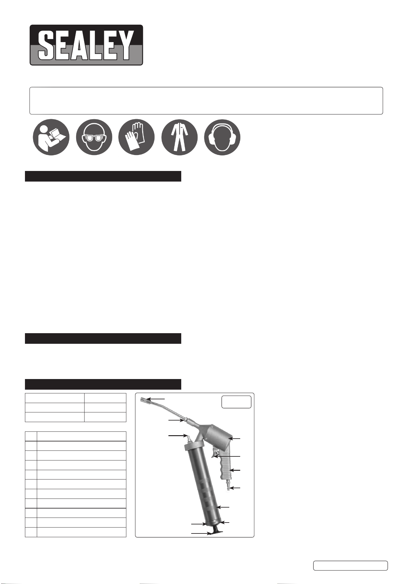
1 Coupler
2 Outlet Nozzle
3 Grease Loader Fitting
4 Pumping Chamber
5 Trigger
6 Die Cast Handle
7 Quick Coupler Air Fitting
8 Barrel
9 Lock Lever
10 End Cap
11 Plunger Rod Handle
g.1
11
10
9
8
7
6
5
4
3
2
1
SA40.V2 (1) 15/01/24
4. PREPARATION FOR USE
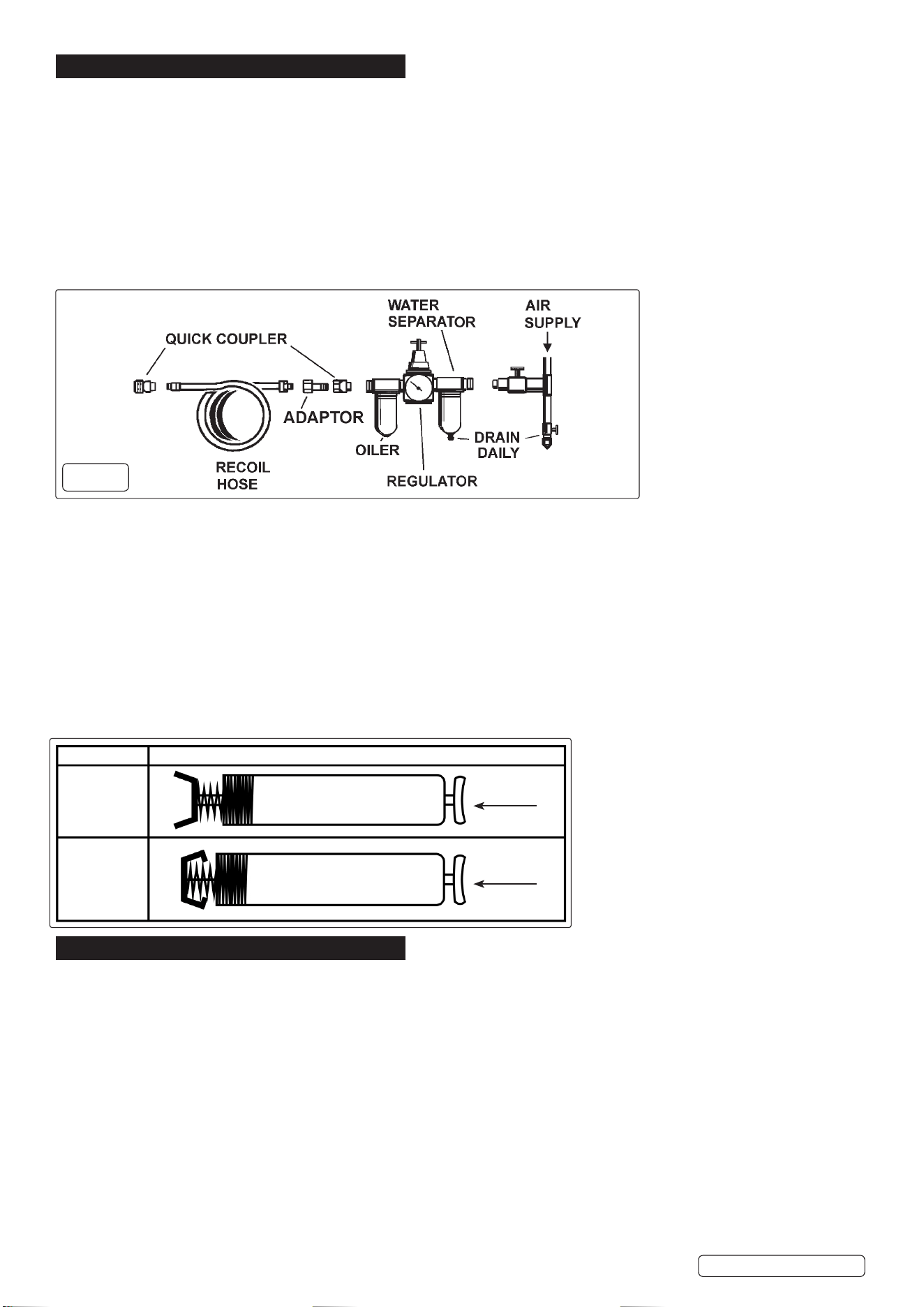
AIR SUPPLY
Recommended hook-up is shown in fig. 2.
4.1. Ensure that the trigger is in the O position when connecting to the air supply.
WARNING! Ensure that the air supply is clean and is between 40-120psi. (3-8 BAR) Too high an air pressure and/or unclean air will
shorten the life of the gun due to excessive wear, and may be dangerous, causing damage and/or personal injury. The recommended
working pressure is 90 PSI (6 BAR). This grease gun has a 40:1 pressure ratio; i.e. the grease discharge pressure will be 40 times the
inlet air pressure.
4.2. Drain the compressor air tank daily. Water in the air line will damage the gun.
4.3. Clean compressor air inlet filter weekly.
4.4. Line pressure should be increased to compensate for unusually long air hoses (over 8 metres). The minimum hose size should be 1/4”
I.D. And fittings must have the same internal bore.
9 Keep hose away from heat, oil and sharp edges. Check hose for wear and make certain that all connections are secure.
LUBRICATION
4.5. Like all air equipment, this grease gun needs regular lubrication. To lubricate, add a few drops of oil through the air inlet on the grease
gun. It is recommended to use SAE 30 or higher viscosity oil.
OPERATING THE GREASE GUN TRIGGER
4.6. This is a one shot grease gun, whereby there is grease discharge with every press of the trigger.
8 DO NOT keep the trigger pressed during operation. The trigger must be repeatedly pressed and released while greasing. Also, DO NOT
repeat the action too fast, as the piston needs to complete a full cycle before starting a new one.
SETTING UP THE GREASE GUN HEAD
Attach the male quick connect coupler air fitting supplied with the gun onto the air inlet on the die cast handle. The male quick connect
coupler air fitting has ¼” NPT threads and should be threaded into the female hole on the die cast handle using thread sealant. Make sure
the connection is tight so that there is no leakage of air. Use PTFE Tape while connecting the air fitting to the air inlet.
CAUTION: Grease or empty cartridge in barrel is under pressure from the internal spring, use caution when removing either end of the
barrel.
HOW TO SELECT FOLLOWER POSITION
5. CHARGING INSTRUCTIONS
WARNING! Ensure that you read, understand and apply the safety instructions before use.
LOADING GREASE GUN
Removing empty Grease Cartridges.
5.6.1. Pull back the plunger handle to its maximum extended position and lock in place.
5.6.2. Un-thread the grease gun head from barrel assembly by turning it counter clockwise. Remove any empty cartridge from the barrel.
INSTALLING GREASE CARTRIDGES
5.1. Pull back the plunger handle to its maximum extended position and lock it in place. Un-thread the grease gun head from barrel
assembly by turning it counter clockwise. Remove any empty cartridge from the barrel.
INSTALLING GREASE CARTRIDGES
NOTE: Choose the correct follower position.
5.1.1. Make sure the gun is disconnected from the air supply. Pull back the follower rod all the way to the end of the barrel & lock it so that the
grease cartridge can be fully inserted.
5.1.2. Un-thread grease gun head from barrel assembly. Remove the plastic cap from the grease cartridge and insert the open end of the
cartridge into the grease gun barrel until the rim of the pull-tab end meets the rim of the grease gun barrel.
5.1.3. Remove the pull-tab seal from top of the cartridge and screw tighten the head onto the barrel while keeping at least 2-3 turns open
before the barrel is fully tightened.
5.1.4. Unlock the plunger rod handle from the end cap. Move the plunger rod forward and backward to remove any trapped air pockets.
g.2
Original Language Version
© Jack Sealey Limited
WARNING! Ensure that you read, understand and
apply the safety instructions before use.
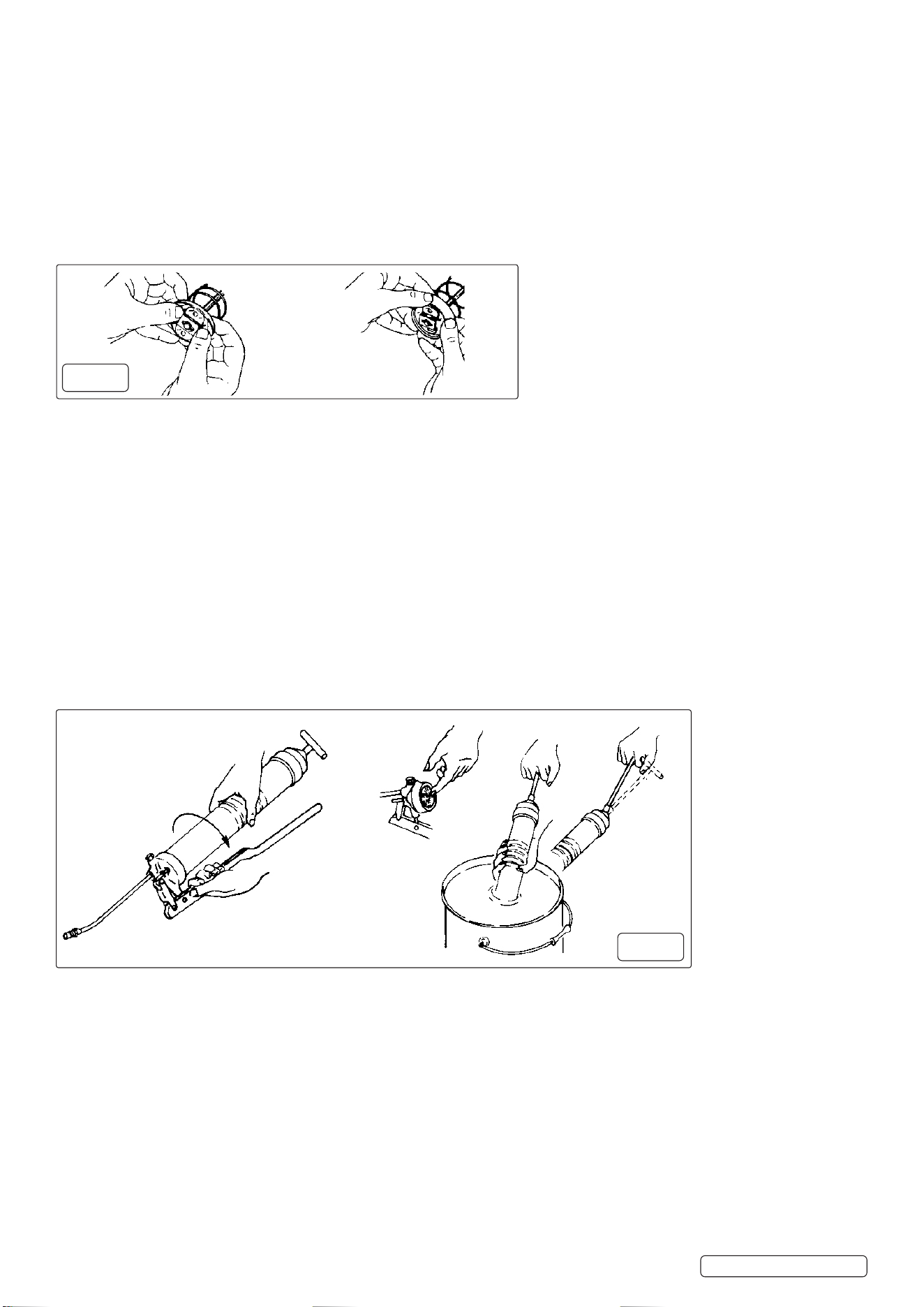
7.3. Cartridge Loading (g. 3)
7.3.1. Remove the gun head from the container tube.
7.3.2. Fully draw back the plunger handle.
7.3.3. Insert the open end of the cartridge into the
container tube and push it all the way in. Remove
the seal or pull tab end from the cartridge.
7.3.4. Reassemble the gun head to the container tube.
Press the catch plate and release the plunger rod.
Push down on the plunger handle.
7.4. Suction Filling (g. 3)
7.4.1. Remove the gun head from the container tube.
7.4.2. Submerge the open end of the container tube into
grease bucket by approximately 50mm (2”) and
slowly pull the plunger handle out fully.
7.4.3. Reassemble the gun head to the container tube.
Press the catch plate and release the plunger rod.
Push down on the plunger handle.
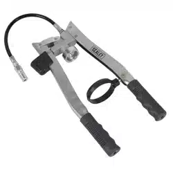
7.5. Loading with Filler Pump (g. 3)
7.5.1. Fully draw back the plunger handle.
7.5.2. Insert ller plug into ller pump socket.
7.5.3. Operate the ller pump to ll the container tube.
7.5.4. Disconnect the grease gun from the ller pump.
7.5.5. Press the catch plate and release the plunger rod.
Push down on the plunger handle.
g.3
SA40.V2 (1) 15/01/24
Grease
Follower Position
Bulk
Cartridge
Push
Push
5.1.5. Connect the air supply and prime the gun by operating the gun by pressing and releasing the trigger until the grease starts coming out
of the discharge nozzle.
5.1.6. Initial grease discharge may have trapped air. Once the gun has been primed, fully tighten the grease gun head onto the barrel.
5.1.7. Push the plunger rod into the barrel for easier manoeuvrability during use.
5.1.8. Connect the grease gun extension and coupler onto the grease gun outlet, it is advisable to use a thread sealant to ensure a leak proof
connection between joints.
Note: DO NOT apply excessive torque or over-tighten the grease gun extension as this will apply undue stress to the die cast outlet
and may cause it to fracture.
TO CONVERT GREASE GUN TO ALLOW FILLING FROM BULK CONTAINER OR FILLER PUMP
5.1.9. Un-thread the barrel cap from barrel assembly and pull out the follower and spring from barrel. Hold Follower between thumb and fore
nger to ip the follower lip from rear to the front side. See g.3.
Note: Always remove any cartridges from the grease gun prior to bulk lling.
5.1.10. Put follower back into barrel, tighten the barrel cap & follower assembly with the barrel.
LOADING GREASE GUN USING BULK GREASE
5.1.11. Make sure the gun is disconnected from the air supply. Pull back the plunger rod handle all the way to the end of the barrel & lock it.
5.1.12. Remove head assembly of grease gun by rotating it in counter-clockwise direction. Release plunger handle and allow the handle to
move to its most forward position. Insert the open end of the barrel into the grease. See g.4.
5.1.13. Slowly pull the plunger rod handle while pushing the barrel deep into the grease until the plunger rod is all the way extended.
5.1.14. The grease gun barrel should now be lled with grease. Wipe the grease from outside surface of barrel before use.
5.1.15. Screw the head of the gun onto the barrel, but do not fully tighten the barrel. For now leave at least 2-3 turns before the barrel is fully
tightened.
5.1.16. Unlock the plunger rod handle from the end cap. Move the plunger rod forward and backward to force out any trapped air pockets from
the connection between the grease gun head and the barrel, which is not fully tightened.
5.1.17. Connect the air supply and prime the gun by operating the gun by pressing and releasing the trigger until the grease starts coming out
of the discharge nozzle. Initial grease discharge may have trapped air. Once the gun has been primed, fully tighten the grease gun
head onto the barrel.
5.1.18. Push the plunger rod into the barrel for easier manoeuvrability during use. Connect the grease gun extension and coupler onto the
grease gun outlet, it is advisable to use a thread sealant to ensure a leak- proof connection between joints.
Note: Do not apply excessive torque or over-tighten the grease gun extension, this will apply undue stress to the die cast outlet and
may cause it to fracture.
LOADING GREASE GUN USING A FILLER PUMP: (FOR MODELS FITTED WITH BULK LOADER VALVE ON GREASE GUN
HEAD)
5.1.19. Wipe the grease gun’s bulk loader clean. Connect the grease gun’s bulk loader valve to the bulk loader adapter on the ller pump.
5.1.20. Start operating the pump to ll grease into the barrel. DO NOT overll grease as this may result in grease leaking from the joints.
5.1.21. Disconnect the grease gun loader adapter from the ller pump. Slightly loosen the grease gun head 2-3 turns. Unlock the plunger
rod handle from the end cap. Move the plunger rod forward and backward to force out any trapped air pockets from the connection
between the grease gun head and the barrel, which is not fully tightened.
5.1.22. Reconnect the air supply and “prime” the system by pressing and releasing the trigger until the grease starts coming out of the
discharge nozzle. Initial grease discharge may have trapped air. Once the gun has been primed, fully tighten the grease gun head onto
the barrel.
5.1.23. Push the plunger rod into the barrel for easier manoeuvrability during use. Connect the grease gun extension and coupler onto the
grease gun outlet. It is advisable to use a thread sealant to ensure a leak- proof connection between joints.
Note: DO NOT apply excessive torque or over-tighten the grease gun extension as this will apply undue stress to the die cast outlet
and may cause it to fracture.
SA40.V2 (1) 15/01/24
Original Language Version
© Jack Sealey Limited
g.4
g.3
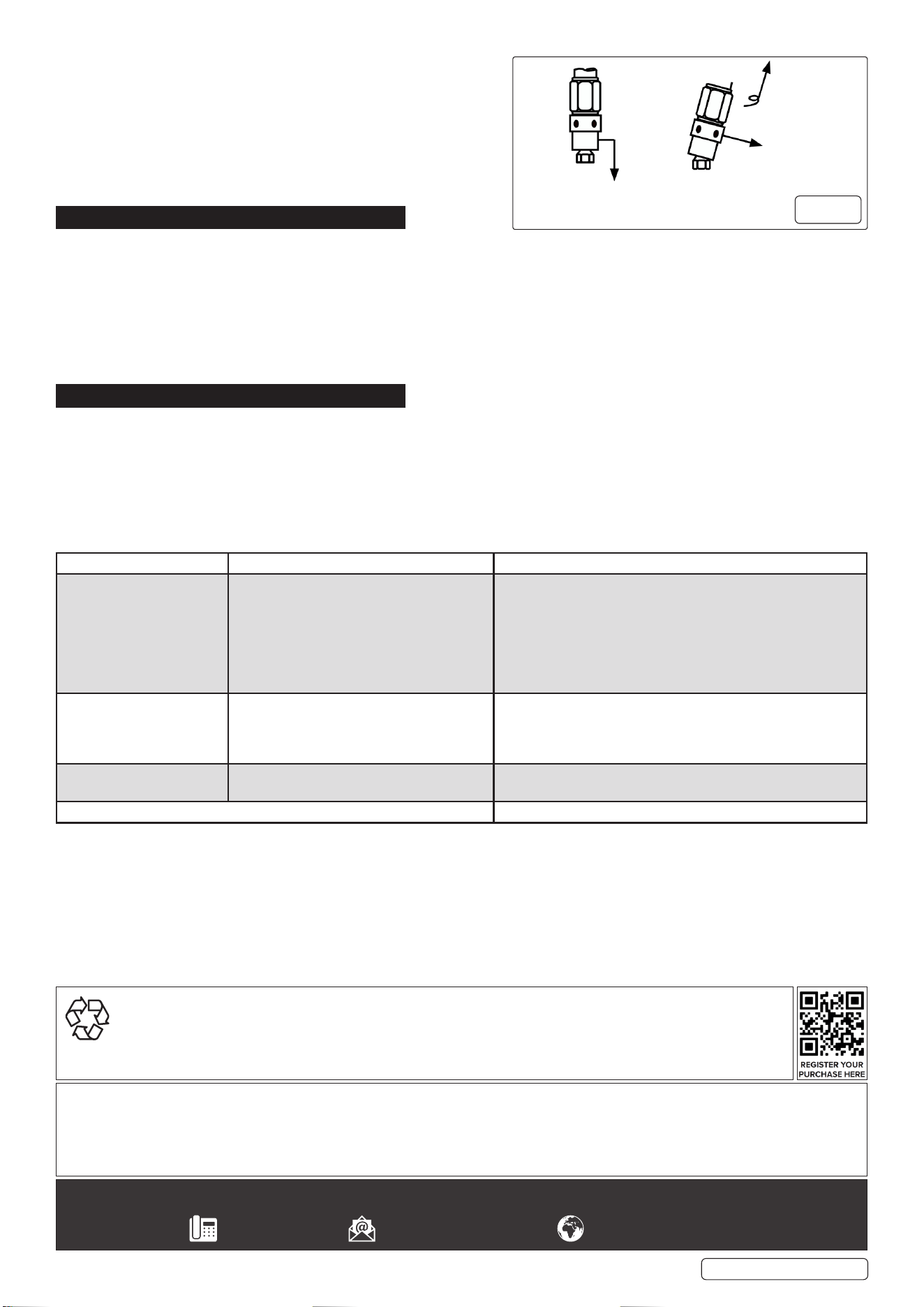
GREASING A GREASE FITTING / GREASE POINT
The grease coupler provided at the end of the grease gun extension
has a jaw type construction. The coupler jaws will snap on to a grease
tting and maintain a tight t. When connecting the coupler to the
grease tting, press the coupler straight onto the grease tting to form
a snug t. Start operating the grease gun with the coupler as square to
the grease tting as possible. Once greasing is completed, slightly tilt
the coupler, twist and pull back. The tilt and twist action will allow easy
removal of the coupler from the grease tting. See g.5.
6. MAINTENANCE
WARNING! Disconnect gun from air supply before changing accessories, servicing or performing maintenance. Replace or repair
damaged parts. Use genuine parts only. Unapproved parts may be dangerous and will invalidate the warranty.
6.1. Lubricate the air tool daily with a good grade of air tool oil such as Sealey ATO/500 or ATO/1000. If the compressed air system has
no oiler, a few drops of oil can be poured into the air inlet of the gun each day.
6.2. When not in use, disconnect from air supply, clean and store in a safe, dry, childproof location.
Note: Faults in the compressed air system may cause loss of power or erratic action. Reduced compressor output, excessive drain on
the air line, moisture or restrictions in air pipes or the use of hose connectors of incorrect size may reduce the air supply.
Grit or gum deposits in the tool will reduce power and may be removed by flushing out the gun with gum solvent oil or an equal mixture
of SAE 10 oil and kerosene.
7. TROUBLESHOOTING
WARNING! If the gun fails to work properly, it may be due to air pockets in the grease. To remove the air, unscrew the gun head 1 to
1½ turns and perform the following:
7.1. Draw back the plunger rod fully and release quickly. Repeat several times. This will exert the force required to move the plunger
into the cartridge (which is essential for the grease gun to work). Push the plunger rod all the way in. Tighten the head to the barrel.
7.2. Press the air vent valve several times to free the air.
Note: If the SA40.V2 is used with cartridges for a long period, it is possible that the rubber plunger may be damaged. If it is, then
if used with dispenser or bulk lling, the plunger may allow grease to seep from the bottom of the container tube. To prevent this
happening, use only one type of ll method for each gun.
PROBLEM CAUSE SOLUTION
Grease gun pumps little or
no grease.
1. Barrel not completely tightened.
2. Air Pockets are trapped in grease.
3. Blocked grease gun extension.
4. Grease too thick or cold.
1. Tighten the barrel completely.
2. Prime grease gun as detailed in instructions.
3. Remove the extension and operate the grease gun. If the gun
dispenses grease then the gun is ne and you need to either
clean the extension or replace it.
4. Store grease gun and grease away from extreme cold or use
thinner grease.
Excessive grease leaking
past the follower.
1. Follower is damaged.
2. Improper seal between the plunger and
the grease gun barrel when using bulk ll or
transfer pump.
Replace the grease gun.
Gun cycles very slowly. Inadequate lubrication of the pumping
chamber.
Put a few drops of lubricator oil through the quick connect
coupler tting.
If the gun still doesn’t operate. Contact nearest authorised service dealer.
SA40.V2 (1) 15/01/24
Original Language Version
© Jack Sealey Limited
Sealey Group, Kempson Way, Suffolk Business Park, Bury St Edmunds, Suffolk. IP32 7AR
01284 757500 sales@sealey.co.uk www.sealey.co.uk
NOTE: It is our policy to continually improve products and as such we reserve the right to alter data, specications and component parts
without prior notice. Please note that other versions of this product are available. If you require documentation for alternative versions, please
email or call our technical team on technical@sealey.co.uk or 01284 757505.
IMPORTANT: No Liability is accepted for incorrect use of this product.
WARRANTY: Guarantee is 12 months from purchase date, proof of which is required for any claim.
ENVIRONMENT PROTECTION
Recycle unwanted materials instead of disposing of them as waste. All tools, accessories and packaging should be
sorted, taken to a recycling centre and disposed of in a manner which is compatible with the environment. When
the product becomes completely unserviceable and requires disposal, drain any uids (if applicable) into approved
containers and dispose of the product and uids according to local regulations.
To engage push
Straight on
To remove, tilt,
twist & pull
g.5