OP70383
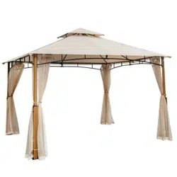
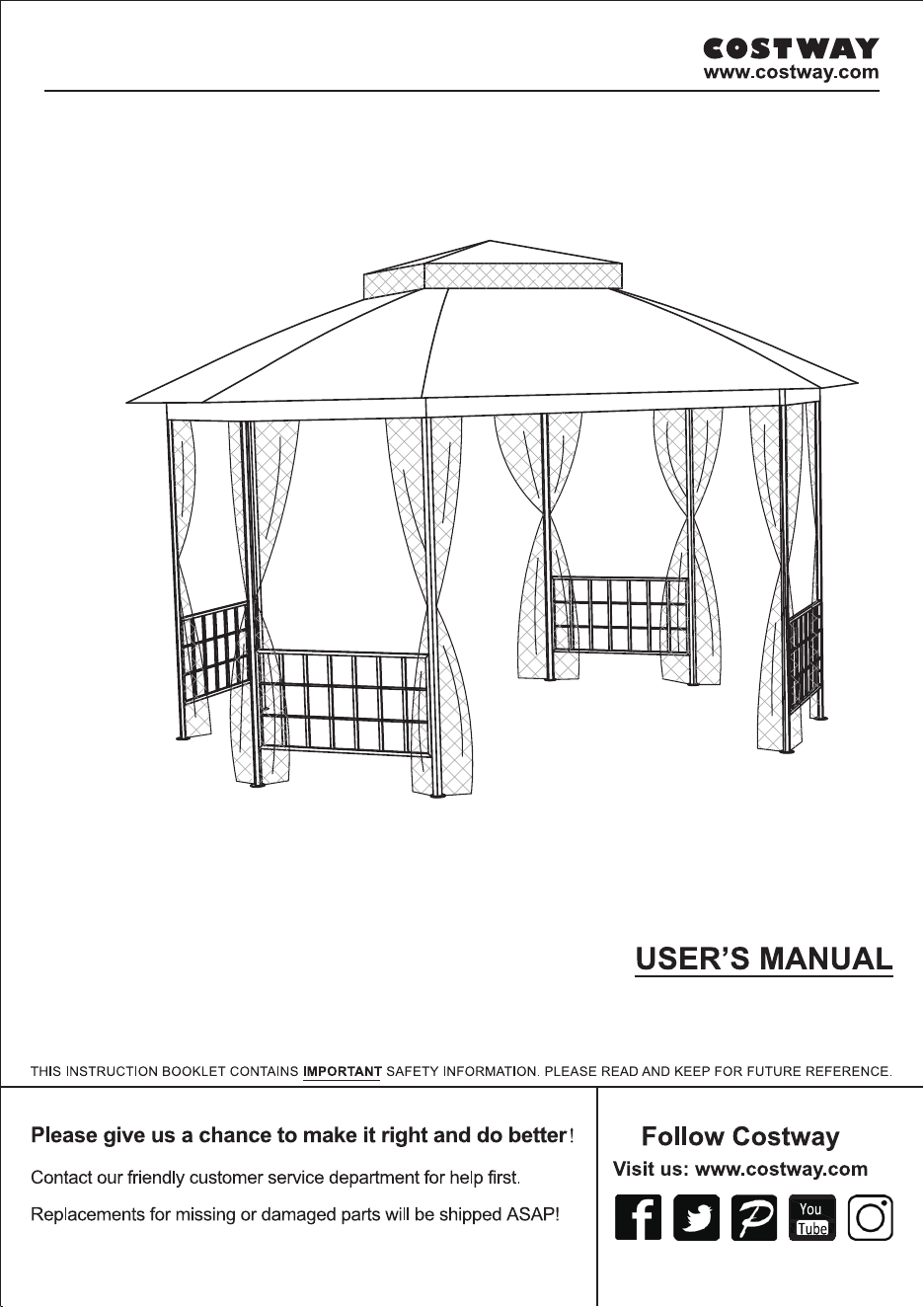
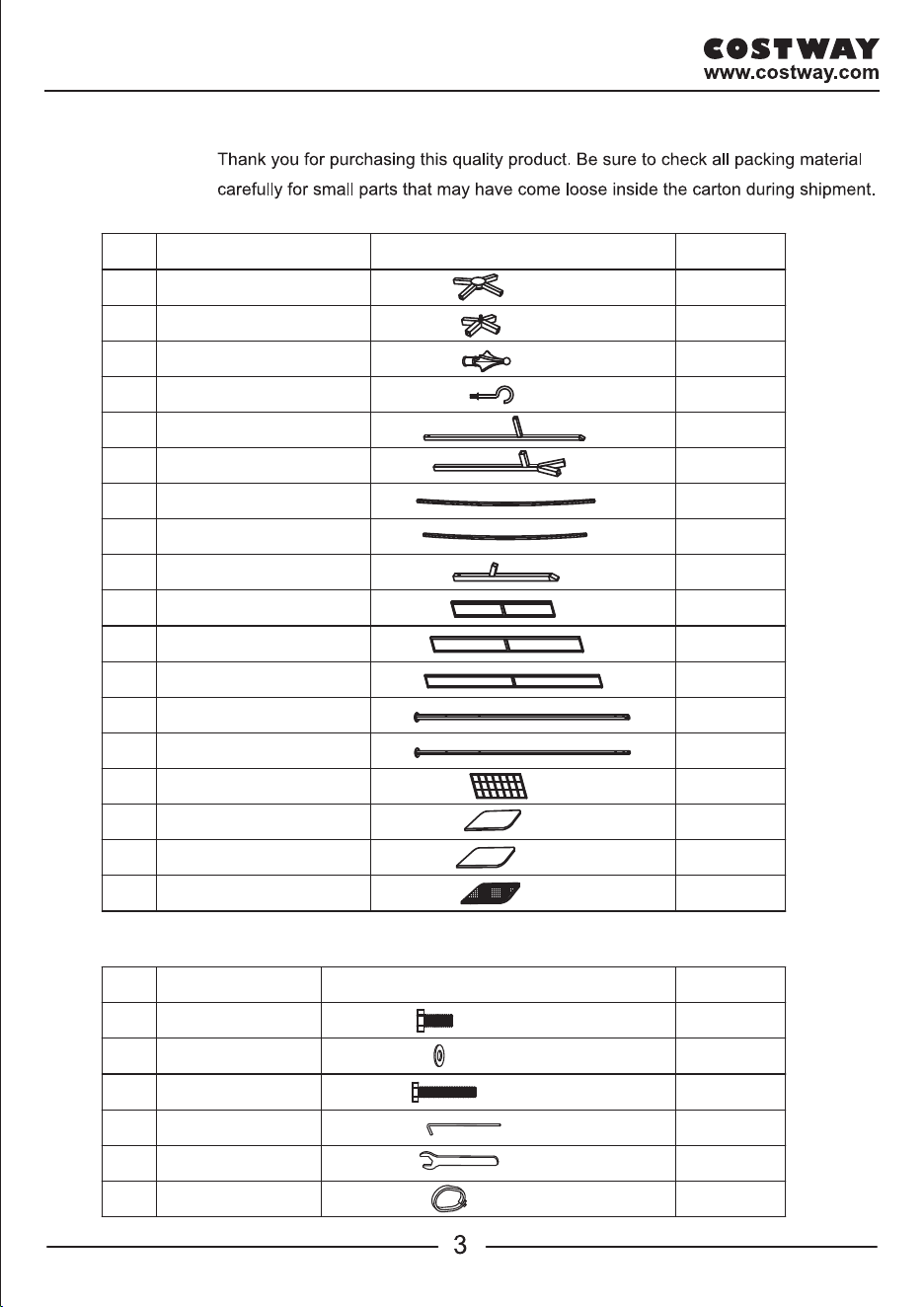
Octagon Metal Gazebo

Description
Sketch
QTY
PARTS LIST
AA
BB
FF
DD
EE
Description
Sketch
QTY
32 PCS
48 PCS
60 PCS
16 PCS
1 PC
HARDWARE LIST
A1
Bolt (M6x15)
Anchor
Wrench
Washer
Small Canpy
4 PCS
2 PCS
4 PCS
4 PCS
2 PCS
1 PC
Top connector 1
Hook
Finial
Connector 1
Side post 1
Corner connector
Screen 1
Post 1
Fence
Large Canopy
Post 2
Top connector 2
A2
Connector 2
Side post 2
Screen 2
Screen 3
Mosquito netting
B1
B2
C1
C2
D1
D2
E
F
G
H
I
J
K
L
M
N
1 PC
1 PC
1 PC
1 PC
4 PCS
4 PCS
4 PCS
8 PCS
4 PCS
4 PCS
1 PC
1 PC
Ring
CC
16 PCS
Bolt (M6x35)
Description
Sketch
QTY
PARTS LIST
AA
BB
FF
DD
EE
Description
Sketch
QTY
32 PCS
48 PCS
60 PCS
16 PCS
1 PC
HARDWARE LIST
A1
Bolt (M6x15)
Anchor
Wrench
Washer
Small Canpy
4 PCS
2 PCS
4 PCS
4 PCS
2 PCS
1 PC
Top connector 1
Hook
Finial
Connector 1
Side post 1
Corner connector
Screen 1
Post 1
Fence
Large Canopy
Post 2
Top connector 2
A2
Connector 2
Side post 2
Screen 2
Screen 3
Mosquito netting
B1
B2
C1
C2
D1
D2
E
F
G
H
I
J
K
L
M
N
1 PC
1 PC
1 PC
1 PC
4 PCS
4 PCS
4 PCS
8 PCS
4 PCS
4 PCS
1 PC
1 PC
Ring
CC
16 PCS
Bolt (M6x35)
F
J
I
K
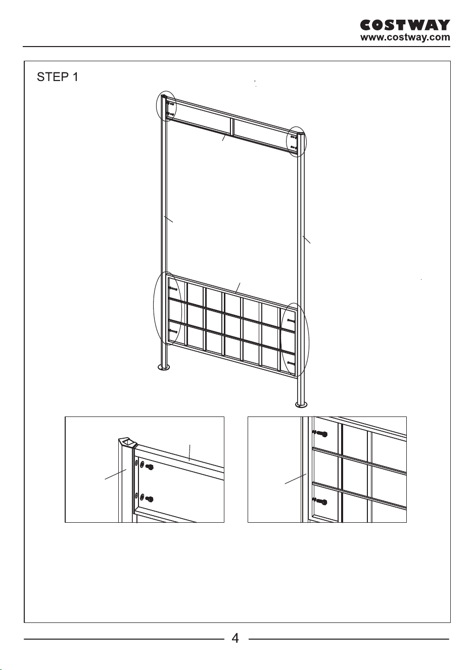
Fig.1: Using bolt (AA) and flat washer (BB) to assemble the screen 1 (F) to the
post 1 (I) or post 2 (J)
Fig.2: Using bolt (CC) and flat washer (BB) to connect the fence (K) to the post 1
(I) or post 2 (J).
Fig.1
Fig.1
Fig.2
Fig.2
H
G
J
J
I
I
Fig.3
Fig.4
Fig.3: Using bolt (AA) and flat washer (BB) to connect the screen 3 (H) to the
post 1 (I) or post 2 (J).
Fig.4: Using bolt (AA) and flat washer (BB) to connect screen 2 (G) to the post 1
(I) or post 2 (J). Secure all bolts by using wrench (EE).
2
BB AA
BB AA
BB AA
I / J
Fig.1 Fig.2
BB CC
BB CC
I / J
F
Fig.3
Fig.4
I / J
H
I / J
G
F
J
I
K
Fig.1: Using bolt (AA) and flat washer (BB) to assemble the screen 1 (F) to the
post 1 (I) or post 2 (J)
Fig.2: Using bolt (CC) and flat washer (BB) to connect the fence (K) to the post 1
(I) or post 2 (J).
Fig.1
Fig.1
Fig.2
Fig.2
H
G
J
J
I
I
Fig.3
Fig.4
Fig.3: Using bolt (AA) and flat washer (BB) to connect the screen 3 (H) to the
post 1 (I) or post 2 (J).
Fig.4: Using bolt (AA) and flat washer (BB) to connect screen 2 (G) to the post 1
(I) or post 2 (J). Secure all bolts by using wrench (EE).
2
BB AA
BB AA
BB AA
I / J
Fig.1 Fig.2
BB CC
BB CC
I / J
F
Fig.3
Fig.4
I / J
H
I / J
G
6
7
STEP 3
A1
C2
D1
D2
D2
D1
E
E
Fig.5
Fig.6
Fig.7
E
Fig.5 Fig.6 Fig.7
A1
C2
C2
B2
C2
D1
D2
Fig.7
E
D1 / D2
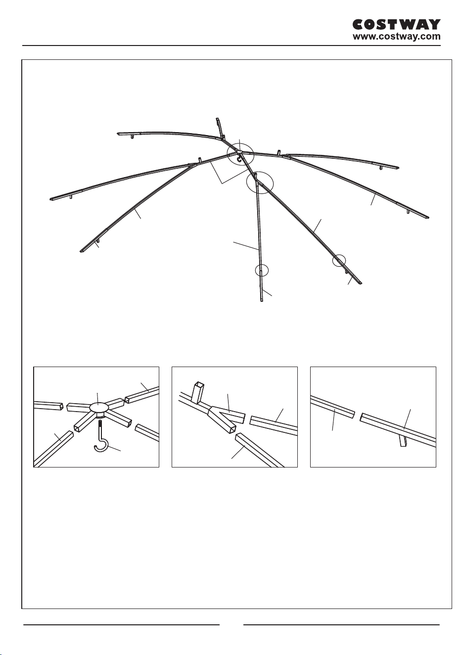
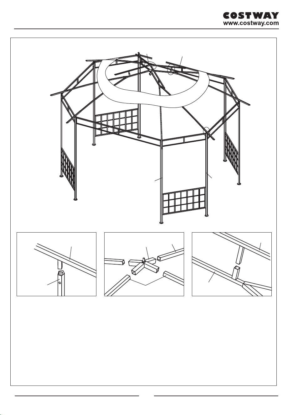
Fig.5: Insert connector 2 (C2) to top connector 1 (A1) and attach hook (B2) to top
connector 1 (A1).
Fig.6: Insert side post 1 (D1) and side post 2 (D2) into connector 2 (C2).
Fig.7: Insert assembly side post 2 (D2) and side post 1 (D1) into corner connector (E).
STEP 4
C1
A2
Fig.9
Fig.10
Fig.8 Fig.9 Fig.10
Fig.8
E
I
J
I / J
A2
C1
C1
C1
C2
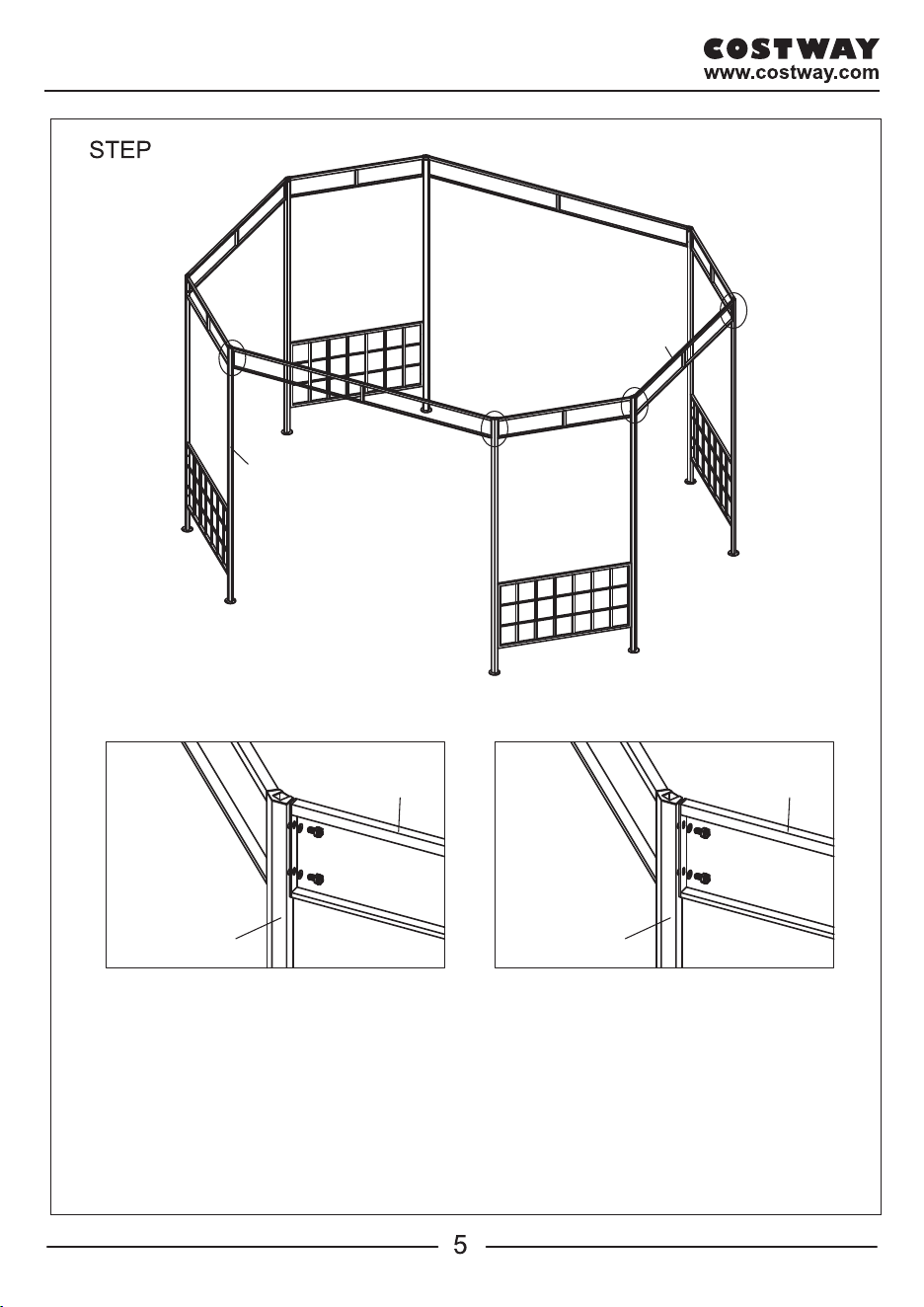
Fig.8: Insert corner connector (E) to the other end of post 1 (I) & post 2 (J). Cover
large canopy (M) to the big top. (Note: The bigger corner of top connector 2 (A2)
should point to the screen 3 (H)).
Fig.9: Insert connector 1 (C1) into top connector 2 (A2), cover small canopy (L) to
Fig.10: Insert the connect tube of connector 1 (C1) onto connector 2 (C2) and
then spread out large canopy (M).
the small top. Then attach finial (B1) to top connector2 (A2).
6
7
STEP 3
A1
C2
D1
D2
D2
D1
E
E
Fig.5
Fig.6
Fig.7
E
Fig.5 Fig.6 Fig.7
A1
C2
C2
B2
C2
D1
D2
Fig.7
E
D1 / D2
Fig.5: Insert connector 2 (C2) to top connector 1 (A1) and attach hook (B2) to top
connector 1 (A1).
Fig.6: Insert side post 1 (D1) and side post 2 (D2) into connector 2 (C2).
Fig.7: Insert assembly side post 2 (D2) and side post 1 (D1) into corner connector (E).
STEP 4
C1
A2
Fig.9
Fig.10
Fig.8 Fig.9 Fig.10
Fig.8
E
I
J
I / J
A2
C1
C1
C1
C2
Fig.8: Insert corner connector (E) to the other end of post 1 (I) & post 2 (J). Cover
large canopy (M) to the big top. (Note: The bigger corner of top connector 2 (A2)
should point to the screen 3 (H)).
Fig.9: Insert connector 1 (C1) into top connector 2 (A2), cover small canopy (L) to
Fig.10: Insert the connect tube of connector 1 (C1) onto connector 2 (C2) and
then spread out large canopy (M).
the small top. Then attach finial (B1) to top connector2 (A2).
8
9
STEP 5
L
M
B1
N
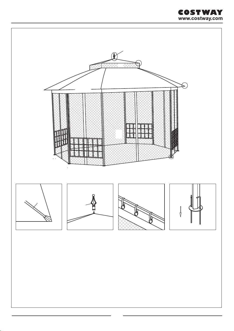
Fig.13: Hanging the mosquito netting (N) to screen 3/1/2 (H/ F/ G) by ring (FF).
Fig.11
L/M
C1/E
Fig.12
Fig.13
Fig.14
Fig.11
Fig.11
Fig.12
B1
N
FF
Fig.13
DD
Fig.14
Fig.14: Fix the gazebo by stake (DD).

8
9
STEP 5
L
M
B1
N
Fig.13: Hanging the mosquito netting (N) to screen 3/1/2 (H/ F/ G) by ring (FF).
Fig.11
L/M
C1/E
Fig.12
Fig.13
Fig.14
Fig.11
Fig.11
Fig.12
B1
N
FF
Fig.13
DD
Fig.14
Fig.14: Fix the gazebo by stake (DD).

OP70383
Octagon Metal Gazebo