ASSEMBLY GUIDE/GUÍA DE ENSAMBLAJE
Before using your new product, please read these instructions to prevent any damage.
Antes de usar su producto nuevo, lea este instructivo para prevenir cualquier daño.
32" to 55" TV WALL MOUNT
MONTAJE DE PARED PARA TELEVISOR
DE 32 A 55 PULG.(Spanish - FPO)
RF-HTMF19

2
Contents
ENGLISH . . . . . . . . . . . . . . . . . . . . . . . . . . . . . . . . . . . . . . . . . . . . . . . . . . . 3
IMPORTANT SAFETY INSTRUCTIONS . . . . . . . . . . . . . . . . . . . . . . . . . . . . . . . . . . . . . . . . . . . . . . . . . . . . . .3
Specifications. . . . . . . . . . . . . . . . . . . . . . . . . . . . . . . . . . . . . . . . . . . . . . . . . . . . . . . . . . . . . . . . . . . . . . . . . . . .3
Tools needed . . . . . . . . . . . . . . . . . . . . . . . . . . . . . . . . . . . . . . . . . . . . . . . . . . . . . . . . . . . . . . . . . . . . . . . . . . . .5
Package contents . . . . . . . . . . . . . . . . . . . . . . . . . . . . . . . . . . . . . . . . . . . . . . . . . . . . . . . . . . . . . . . . . . . . . . . .6
Installation instructions . . . . . . . . . . . . . . . . . . . . . . . . . . . . . . . . . . . . . . . . . . . . . . . . . . . . . . . . . . . . . . . . . .9
STEP 1 - Determine whether your TV has a flat, irregular, or obstructed back. . . . . . . . . . . . .9
STEP 2 - Select screws, washers, and spacers. . . . . . . . . . . . . . . . . . . . . . . . . . . . . . . . . . . . . . . . . . .10
STEP 3 - Attach the horizontal brackets to your TV . . . . . . . . . . . . . . . . . . . . . . . . . . . . . . . . . . . . .11
STEP 4 - Attach the vertical bracket to your TV. . . . . . . . . . . . . . . . . . . . . . . . . . . . . . . . . . . . . . . . .12
STEP 5 - Determine the wall-mount location. . . . . . . . . . . . . . . . . . . . . . . . . . . . . . . . . . . . . . . . . . .13
STEP 6 - Option 1: Install on a wood stud wall . . . . . . . . . . . . . . . . . . . . . . . . . . . . . . . . . . . . . . . . .14
STEP 6 - Option 2: Install on a solid concrete or concrete block wall . . . . . . . . . . . . . . . . . . . .17
STEP 7 - Attach the TV . . . . . . . . . . . . . . . . . . . . . . . . . . . . . . . . . . . . . . . . . . . . . . . . . . . . . . . . . . . . . . . .20
STEP 8 - Manage cables. . . . . . . . . . . . . . . . . . . . . . . . . . . . . . . . . . . . . . . . . . . . . . . . . . . . . . . . . . . . . . .22
STEP 9 - Adjust the tilt . . . . . . . . . . . . . . . . . . . . . . . . . . . . . . . . . . . . . . . . . . . . . . . . . . . . . . . . . . . . . . . .22
STEP 10 - Adjust the level . . . . . . . . . . . . . . . . . . . . . . . . . . . . . . . . . . . . . . . . . . . . . . . . . . . . . . . . . . . . .23
Remove your TV from the wall mount. . . . . . . . . . . . . . . . . . . . . . . . . . . . . . . . . . . . . . . . . . . . . . . . .24
LIFETIME LIMITED WARRANTY . . . . . . . . . . . . . . . . . . . . . . . . . . . . . . . . . . . . . . . . . . . . . . . . . . . . . . . . . . .26
Contenido
ESPAÑOL. . . . . . . . . . . . . . . . . . . . . . . . . . . . . . . . . . . . . . . . . . . . . . . . . . 28
INSTRUCCIONES IMPORTANTES DE SEGURIDAD. . . . . . . . . . . . . . . . . . . . . . . . . . . . . . . . . . . . . . . . . .28
Especificaciones . . . . . . . . . . . . . . . . . . . . . . . . . . . . . . . . . . . . . . . . . . . . . . . . . . . . . . . . . . . . . . . . . . . . . . . .28
Herramientas requeridas. . . . . . . . . . . . . . . . . . . . . . . . . . . . . . . . . . . . . . . . . . . . . . . . . . . . . . . . . . . . . . . .30
Contenido del paquete . . . . . . . . . . . . . . . . . . . . . . . . . . . . . . . . . . . . . . . . . . . . . . . . . . . . . . . . . . . . . . . . .31
Instrucciones de instalación. . . . . . . . . . . . . . . . . . . . . . . . . . . . . . . . . . . . . . . . . . . . . . . . . . . . . . . . . . . . .34
PASO 1 - Determine si su televisor tiene una parte posterior plana, irregular u obstruida.34
PASO 2 - Selección de los tornillos, arandelas y espaciadores. . . . . . . . . . . . . . . . . . . . . . . . . . .35
PASO 3: Colocación de los soportes horizontales en su televisor. . . . . . . . . . . . . . . . . . . . . . . .36
PASO 4: Colocación del soporte horizontal a su televisor. . . . . . . . . . . . . . . . . . . . . . . . . . . . . . .38
PASO 5 - Determine la ubicación del montaje en pared . . . . . . . . . . . . . . . . . . . . . . . . . . . . . . . .39
PASO 6 - Opción 1: Instale en una pared con viga de madera. . . . . . . . . . . . . . . . . . . . . . . . . . .40
PASO 6 - Opción 2: Instalación en una pared de concreto sólido o de bloques de concreto43
PASO 7: Coloque el televisor . . . . . . . . . . . . . . . . . . . . . . . . . . . . . . . . . . . . . . . . . . . . . . . . . . . . . . . . . .46
Paso 8 - Organización de los cables . . . . . . . . . . . . . . . . . . . . . . . . . . . . . . . . . . . . . . . . . . . . . . . . . . .48
PASO 9: Ajuste de la inclinación . . . . . . . . . . . . . . . . . . . . . . . . . . . . . . . . . . . . . . . . . . . . . . . . . . . . . . .48
PASO 10 - Ajuste el nivel . . . . . . . . . . . . . . . . . . . . . . . . . . . . . . . . . . . . . . . . . . . . . . . . . . . . . . . . . . . . . .49
Retire su televisor del montaje en pared. . . . . . . . . . . . . . . . . . . . . . . . . . . . . . . . . . . . . . . . . . . . . . .50
GARANTÍA LIMITADA DE POR VIDA. . . . . . . . . . . . . . . . . . . . . . . . . . . . . . . . . . . . . . . . . . . . . . . . . . . .53

3
RF-HTMF19
ENGLISH
Introduction
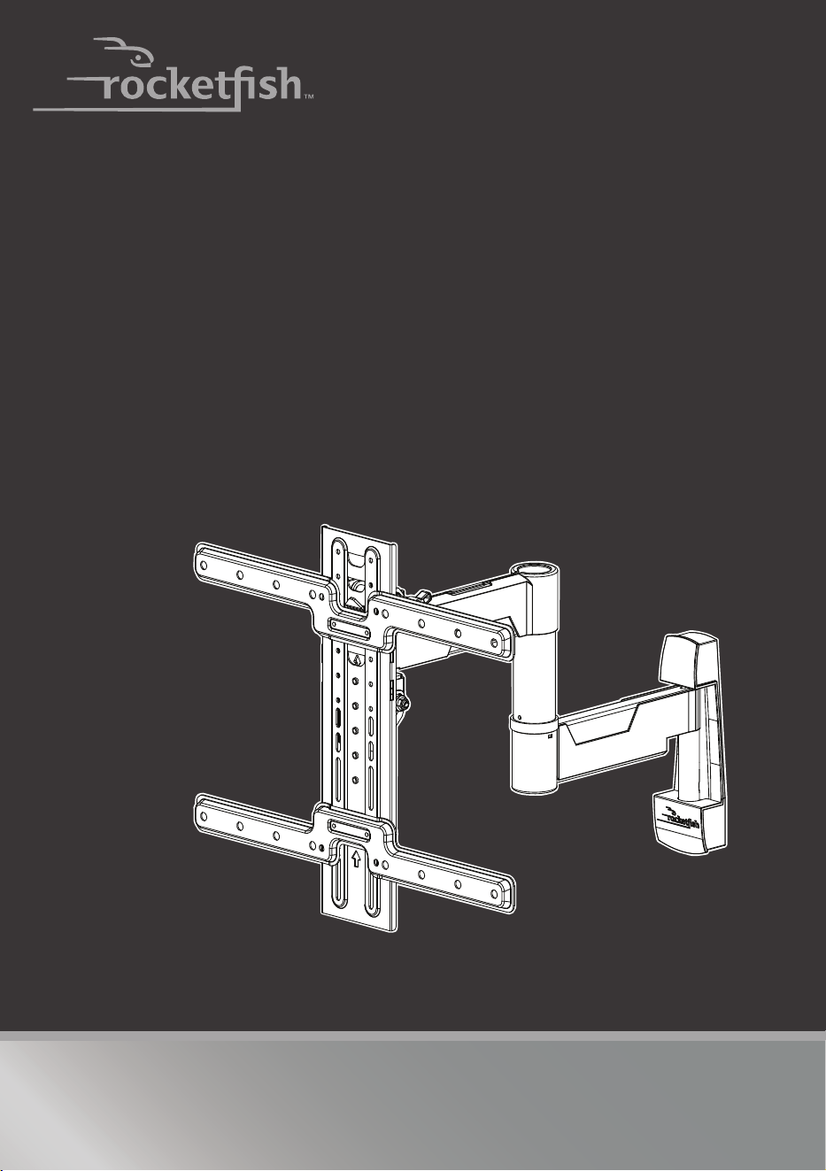
Congratulations on your purchase of a high-quality Rocketfish product. Your
RF-HTMF19 represents the state of the art in TV wall-mount design and is designed
for reliable and trouble-free performance.
IMPORTANT SAFETY INSTRUCTIONS
SAVE THESE INSTRUCTIONS
• This product is designed ONLY to be installed into wood studs, solid concrete, or
concrete block.
• DO NOT INSTALL INTO DRYWALL ALONE — DRYWALL ALONE WILL NOT HOLD THE
WEIGHT OF YOUR TV.
• This product is designed for INDOOR USE ONLY.
• The wall must be capable of supporting five times the weight of the TV and mount
combined.
• Do not use this product for any purpose not explicitly specified by the manufacturer.
• The manufacturer is not responsible for damage or injury caused by incorrect assembly
or use.
• Improper installation may cause property damage or personal injury. If you do not
understand these directions, or have doubts about the safety of the installation, contact
Customer Service or call a qualified contractor. Rocketfish is not responsible for damage
or injury caused by incorrect installation or use.
• The weight of your TV and accessories must not exceed 55 lbs. (24.9 kg).
• This product contains small items that could be a choking hazard if swallowed. Keep
these items away from young children!
Specifications
• Maximum TV weight: 55 lbs. (24.9 kg)
• Screen size: From 32 in. to 55 in. (81.3 cm to 139.7 cm) diagonal
• Overall dimensions (H × W): 17.2 × 17.2 in. (43.6 cm × 43.6 cm)
• Wall-mount weight: 7.3 lbs. (3.31 kg)
• VESA patterns: 75 × 75 to 400 × 400 (with all common sizes in between)
• For customer service, call: 1-800-620-2790
4
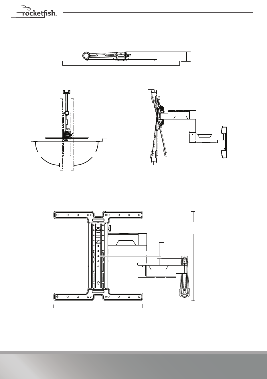
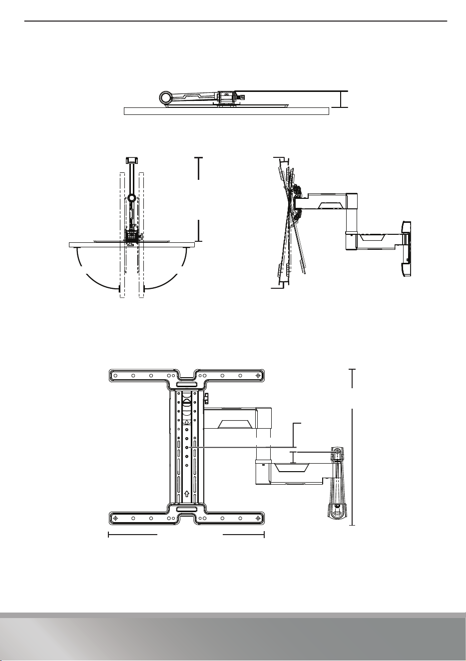
Dimensions
19.2in.
(48.8 cm)
90°
90°
15°
Down
5° Up
2.2 in. (5.7 cm)
Top View
Side/Tilt View
Top View Extended
17.2 in. (43.6 cm)
17.2 in. (43.6 cm)
.6 in. (1.6 cm)
Vertical centerline
Dimensions for mounting
(also see Step 5)
5
RF-HTMF19
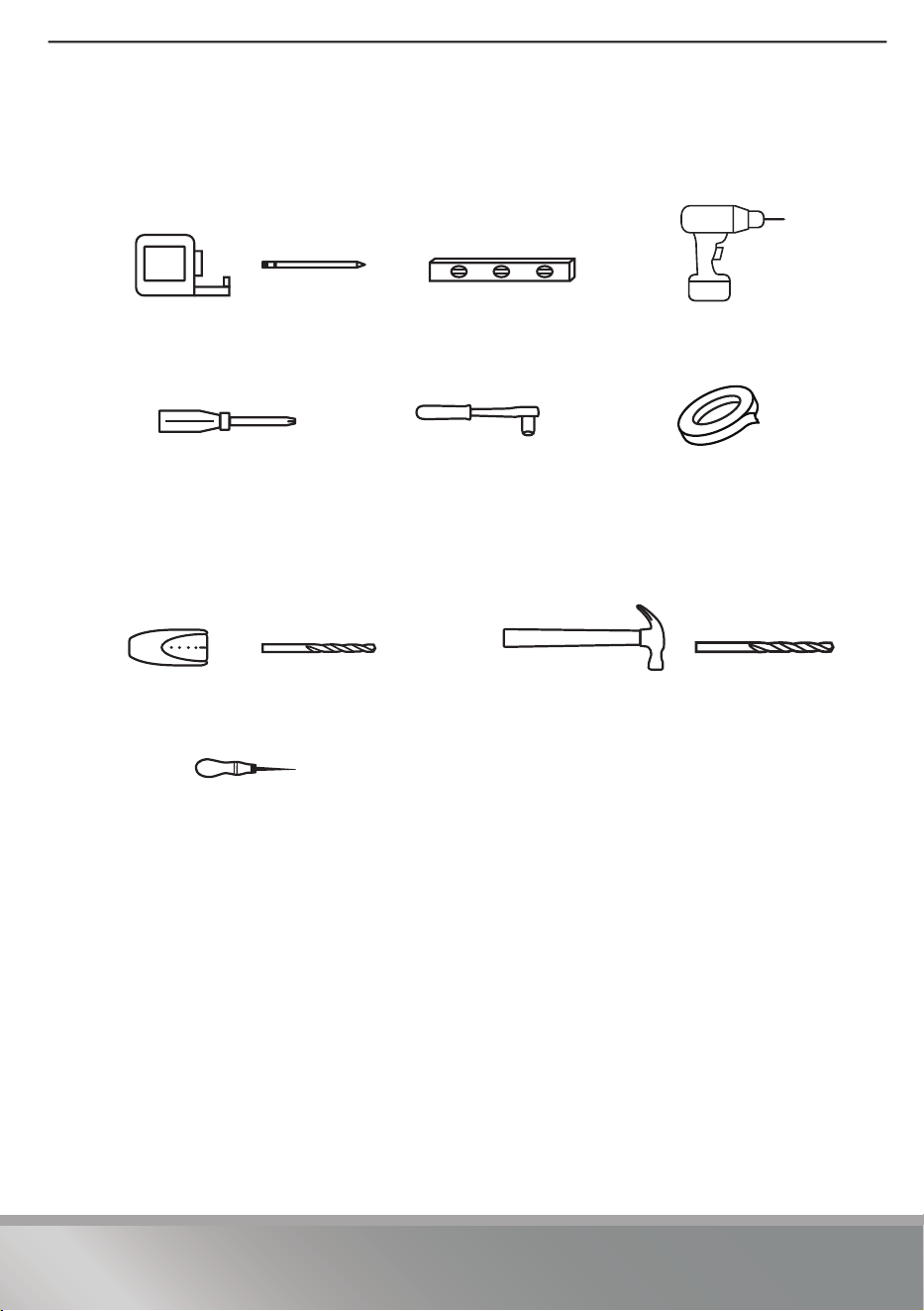
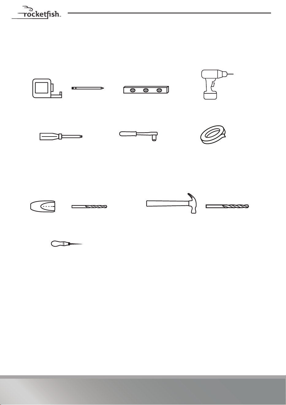
Tools needed
You need the following tools to assemble your new TV wall mount:
Edge-to-edge
stud finder
Pencil Level
Socket wrench with 1/2" (13 mm)
socket or adjustable wrench
Tape measure Drill
Tape
Hammer
Wood Stud Wall
Concrete or Concrete Block Wall
3/8" (10 mm)
masonry drill bit
7/32" (5.5 mm)
wood drill bit
Awl
Phillips screwdriver
6
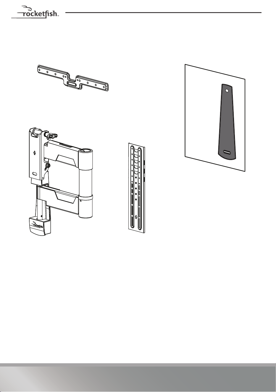
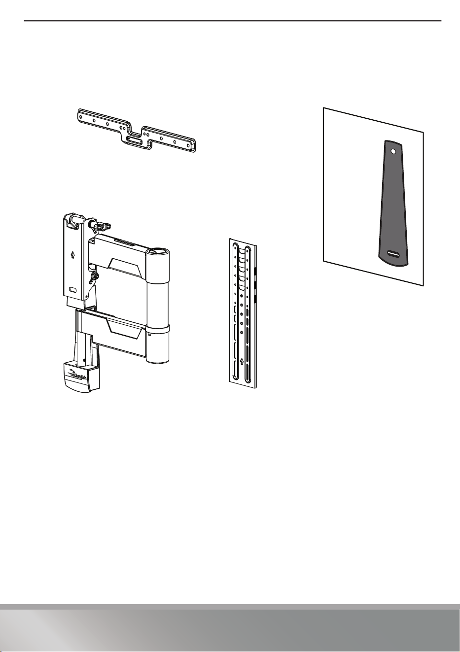
Package contents
Make sure that you have all the hardware necessary to assemble your new TV wall
mount:
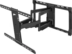
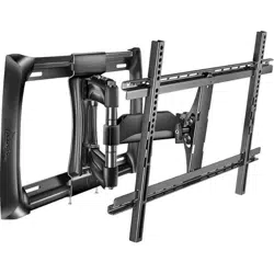
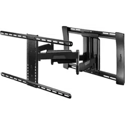
08 TV arm assembly
07 Mounting template
04 Horizontal TV brackets (2)
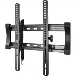
05 Vertical TV bracket
7
RF-HTMF19
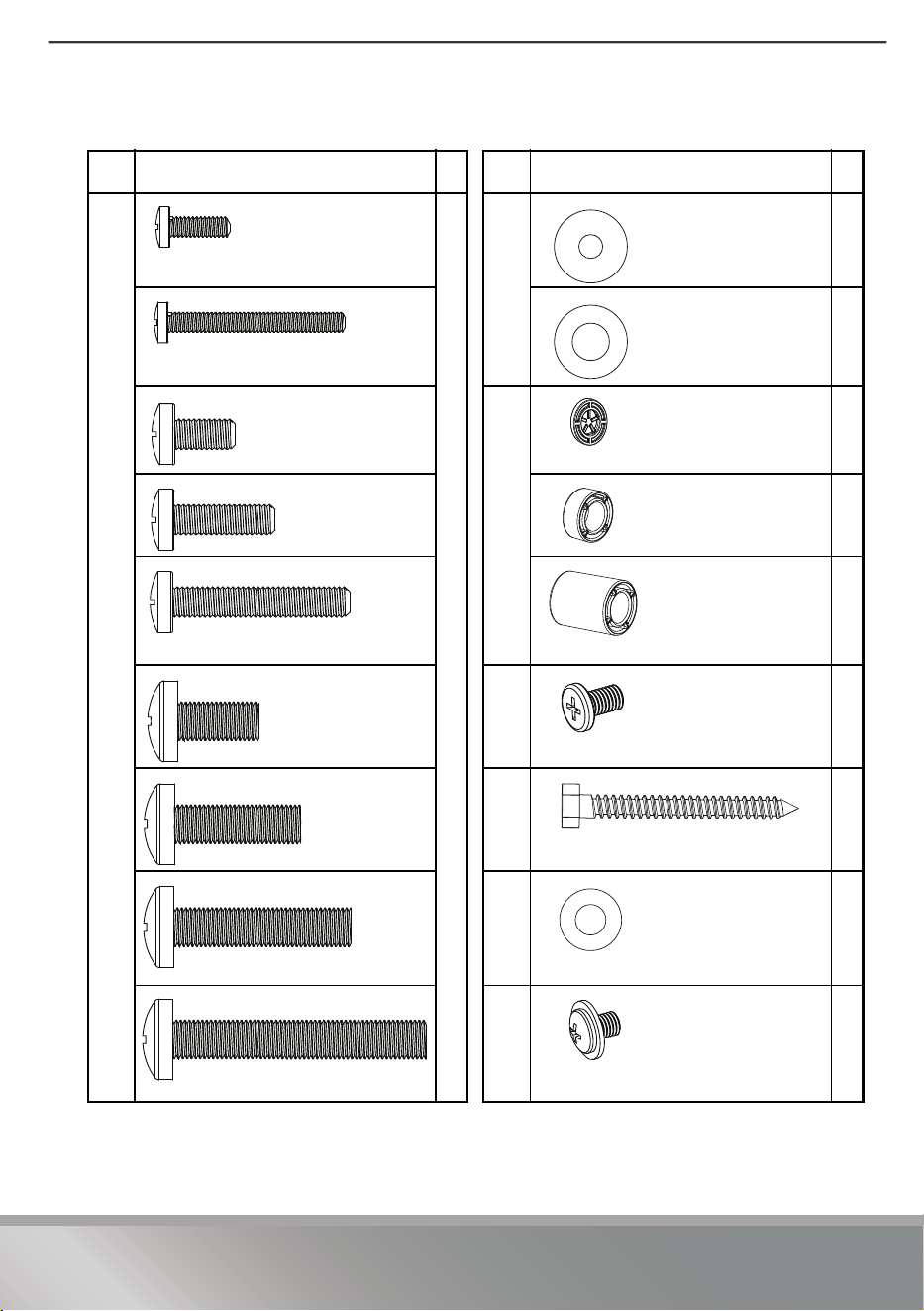
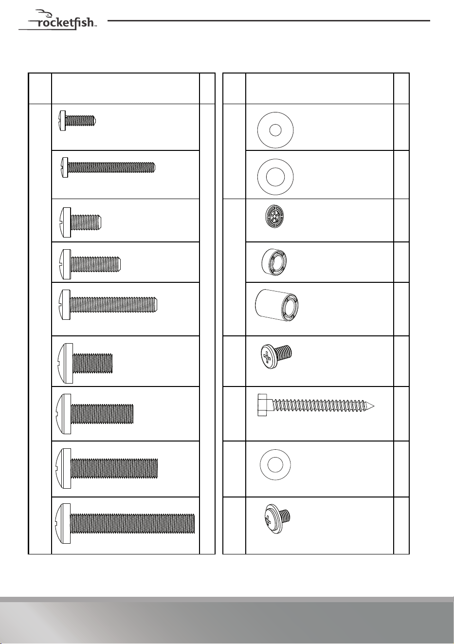
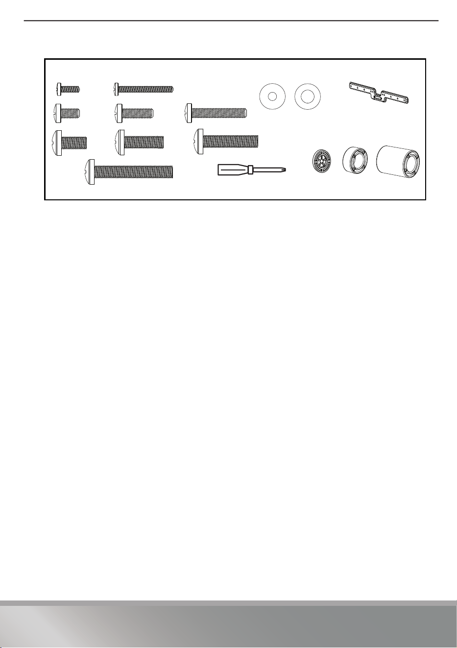
TV Hardware
Lbl. Hardware # Lbl. Hardware #
01
4
02
4
4
03
4
4
4
06
4
09
2
10
2
11
1
M4 × 12 mm screw
M4 washer
M4 × 35 mm screw
M6/M8 washer
M6 × 12 mm screw
Spacer (2.5 mm)
M6 × 20 mm
screw
Spacer (5 mm)
M6 × 35 mm screw
Spacer (22 mm)
M8 × 16 mm
screw
TV bracket screw
M5 × 8.5 mm
M8 × 25 mm
screw
Lag screw 5/16 × 2 3/4 in.
M8 × 35 mm screw
Washer 5/16 in.
M8 × 50 mm screw
Locking screw
M5 x 6 mm
8
Concrete Installation Kit CMK1 (not included)
Contact customer service at 1-800-620-2790 to have these additional parts shipped
directly to you.
Lbl. Hardware #
C1 2
Concrete anchors
(Fischer UX10 x 60R)
9
RF-HTMF19
Installation instructions
STEP 1 - Determine whether your TV has a flat, irregular,
or obstructed back
1 Carefully place your TV face-down on a cushioned, clean surface to protect the
screen from damages and scratches.
2 If your TV has a table-top stand attached, remove the stand. See the
documentation that came with your TV for instructions.
3 Temporarily lay the horizontal brackets (
04) on the back of your TV.
4 Align the screw holes in the brackets with the mounting screw holes on your TV.
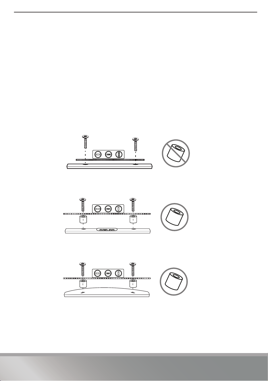
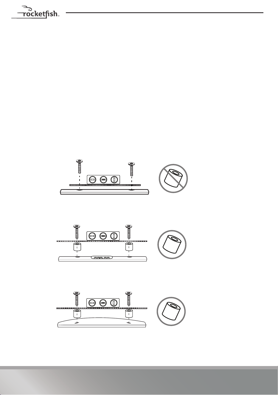
5 Identify which type of back your TV has:
• Flat back: The brackets lay flush against the back of your TV and do not block
any jacks. You do not need spacers when assembling the wall mount.
• Obstructed back: The brackets block any of the jacks on the back of your TV.
You need 2.5 mm, 5 mm, or 22 mm spacers (03) when assembling the wall
mount.
• Irregularly-shaped back: There is a gap between the brackets and some part
of the back of your TV. You need 2.5 mm, 5 mm, or 22 mm spacers (03) when
assembling the wall mount.
6 Remove the brackets.
10
STEP 2 - Select screws, washers, and spacers
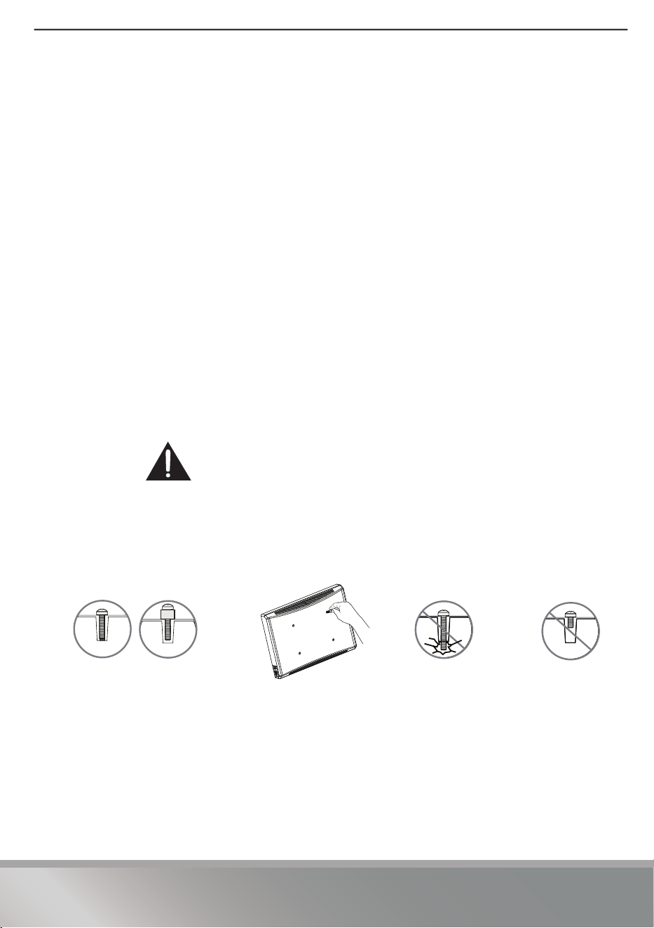
1 Select the hardware for your TV (screws, washers, and spacers). A limited number
of TVs come with mounting hardware included. (If screws came with your TV,
they are almost always in the holes on the back of your TV.) If you don't know the
correct length of the mounting screws your TV requires, test various sizes by
hand threading the screws.
Select the screws that fit:
Use the M4 washers (02) for M4 screws and M6/M8 washers (02) for all M6 or M8
screws. For an irregular or obstructed TV back, also use the 2.5 mm, 5 mm, or
22 mm spacers (
03).
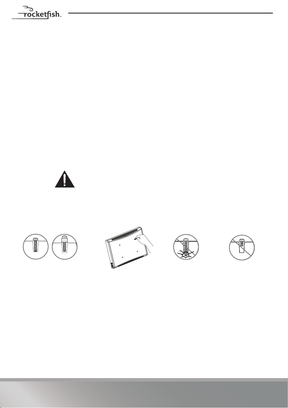
CAUTION: To avoid potential personal injuries and property damage,
make sure that the screws have adequate threads to secure the brackets
to your TV. If you encounter resistance, stop immediately and contact
customer service. Use the shortest screw and spacer combination to
accommodate your TV. Using hardware that is too long may damage your TV.
However, using a screw that is too short may cause your TV to fall from the mount.
2 Remove the screws.
M4 × 12 mm screws (01)M8×16mm screws (01)
M4 × 35 mm screws (01)M8×25mm screws (01)
M6 × 12 mm screws (01)M8×35mm screws (01)
M6 × 20 mm screws (01)M8×50mm screws (
01)
M6 × 35 mm screws (01)
Screw is
too long
Screw fits
correctly
Screw is
too short
11
RF-HTMF19
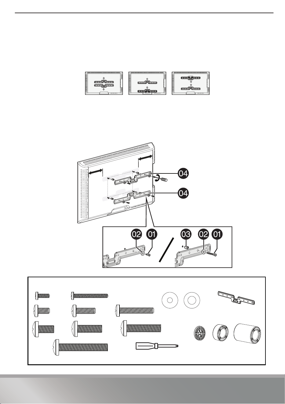
STEP 3 - Attach the horizontal brackets to your TV
CAUTION: To avoid personal injury or property damage, do not use power tools.
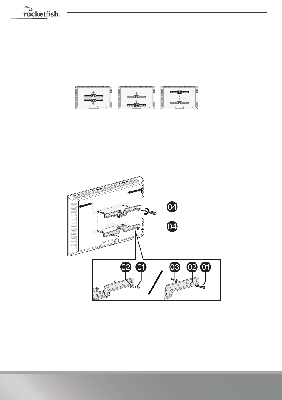
1 Align the holes you noted on the horizontal brackets (04) with the screw holes
on the back of your TV.
2 Place the washers (
02) over the holes in the brackets that align with the screw
holes on the back of your TV, then insert the screws that you selected in
STEP 2 (
01) through the washers. Make sure that the brackets are level.
3 Add spacers (03) if you determined that spacers are required in STEP 1.
4 Tighten the screws until they are snug against the brackets. Do not over tighten.
You’ll need
02 Washers (4)
01 Screws (4)
OR
04 Horizontal TV
brackets (2)
OR
OR
OR
Phillips screwdriver
OR
OR
03 Spacers (4)
12
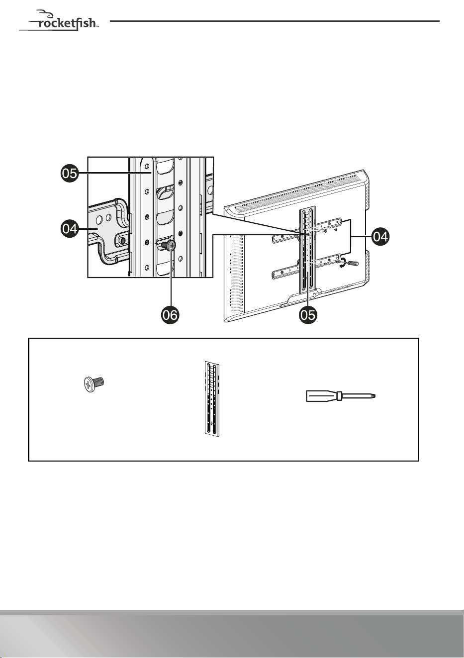
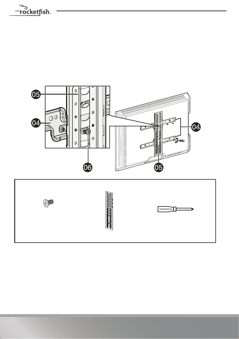
STEP 4 - Attach the vertical bracket to your TV
CAUTION: To avoid personal injury or property damage, do not use power tools.
1 Lay the vertical bracket (05) on top of the horizontal brackets (04). Make sure
that the bracket is centered.
2 Secure the vertical bracket (
05) to the horizontal brackets with the TV bracket
screws (
06). Tighten the screws until they are snug against the vertical brackets.
Do not over tighten.
You’ll need
06 TV bracket
screws (4)
Phillips screwdriver
05 Vertical TV bracket (1)
13
RF-HTMF19
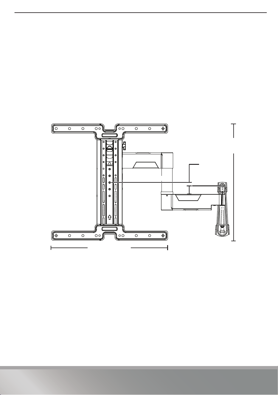
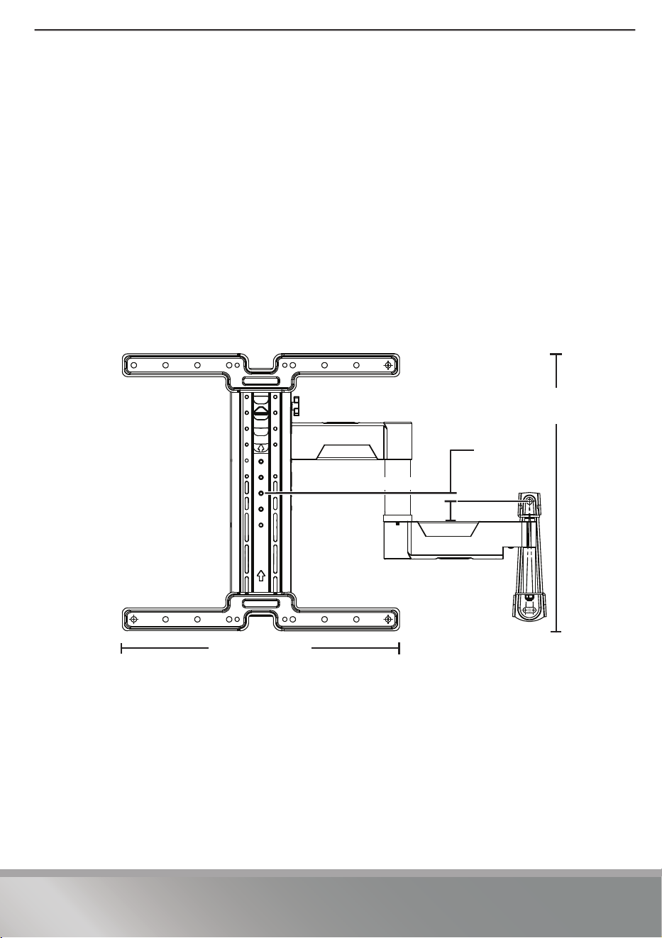
STEP 5 - Determine the wall-mount location
Note: Your TV should be high enough so your eyes are level with the middle of the
screen from a seated position (normally, 40 to 60 inches from the ground).
For more detailed information on determining where to drill your holes, visit our
online height-finder at: http://bestbuy.selectionassistant.com/heightfinder/#!step1
The center of the TV arm assembly (08) is NOT the same as the center of the Vertical
TV bracket (05). The center of the Vertical TV bracket is HIGHER than the center of the
TV arm assembly. When the center slot of the Vertical TV bracket is used, the top hole
in the TV arm assembly will be 0.6 in below the center of the Vertical TV bracket and
the center point of your TV.
VESA mounting patterns are not centered on all TVs. You will need to account for the
location of the VESA when determining the height of the TV arm assembly.
17.2 in. (43.6 cm)
17.2 in. (43.6 cm)
.6 in. (1.6 cm)
Vertical centerline
14
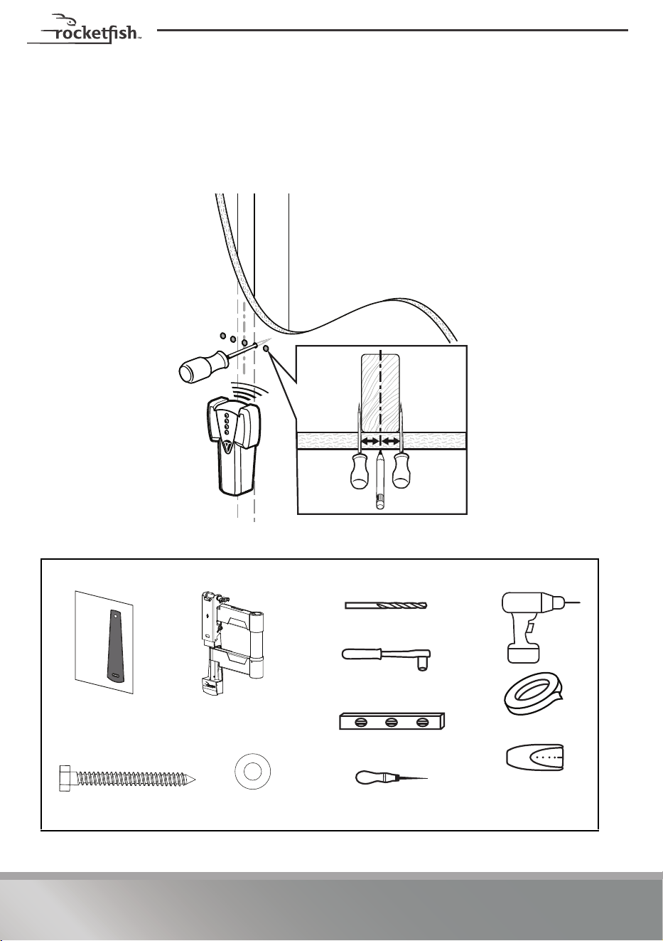
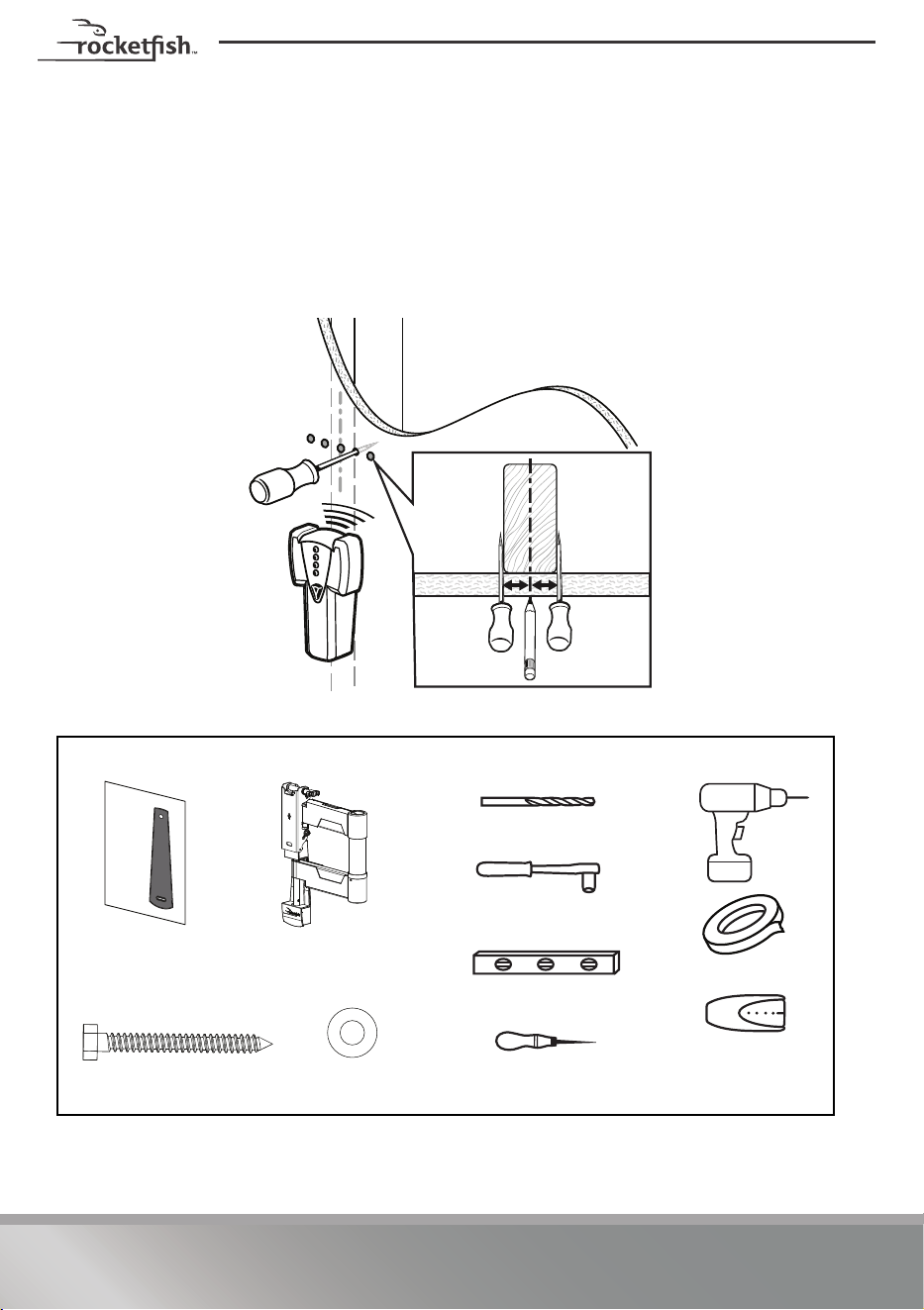
STEP 6 - Option 1: Install on a wood stud wall
1 Locate the stud, then verify the center of the stud with an edge-to-edge stud
finder or an awl.
Caution:
Drywall covering the wall must not exceed 5/8 in. (1.6 cm).
Minimum wood stud size: nominal 2 × 4 in. (5.1 × 10.2 cm) actual 1 1/2 × 3 1/2 in. (3.8 × 8.9 cm).
You’ll need
Edge-to edge
stud finder
09 Lag screw (2)
Drill
7/32" wood drill bit
1/2" socket wrench
07 Mounting
template
Tape
08 TV arm assembly
Level
10 Washer (2) Awl
15
RF-HTMF19
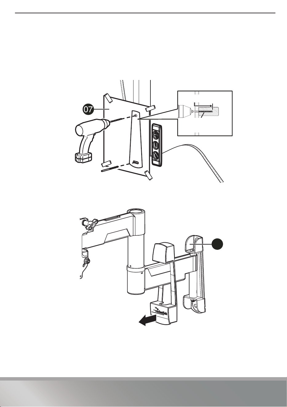
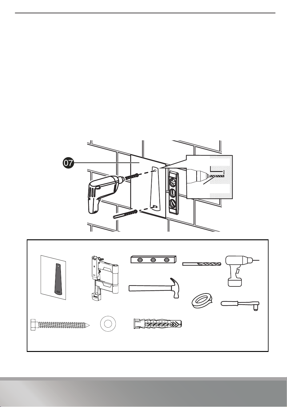
2 Align the center of the mounting template (07) at the height you determined in
the previous step and make sure that it is level. Tape the mounting template to
the wall.
3 Drill two pilot holes through the mounting template to a depth of 2 3/4 in.
(70 mm) using a 7/32 in. (5.5 mm) diameter drill bit, then remove the mounting
template.
4 Move the cover out away from the arm assembly wall plate.
(69 mm)
7/32 in
(5.5 mm)
7/32 in. (5.5 mm)
2 3/4 in. (70 mm)
08
16
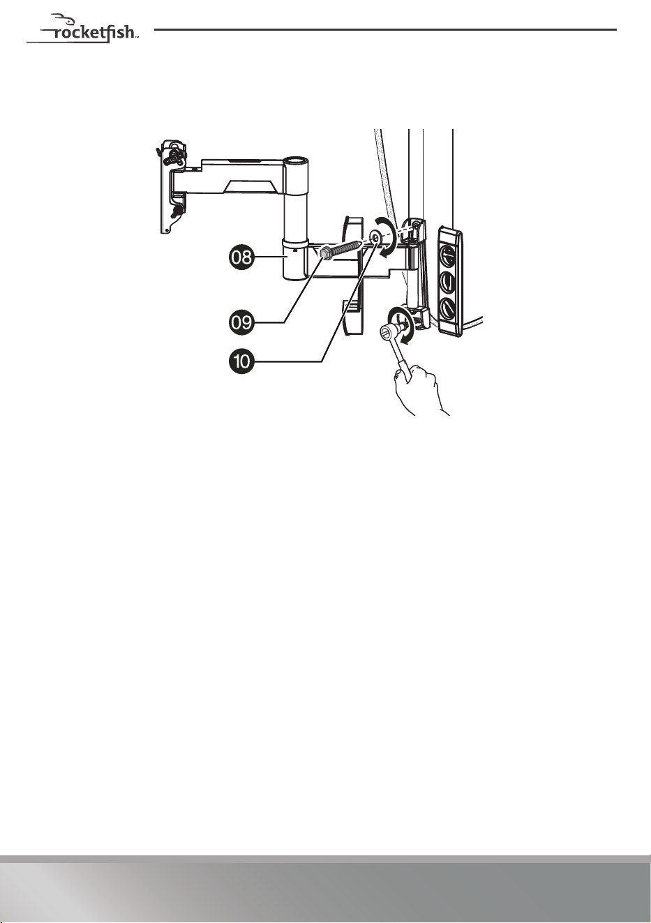
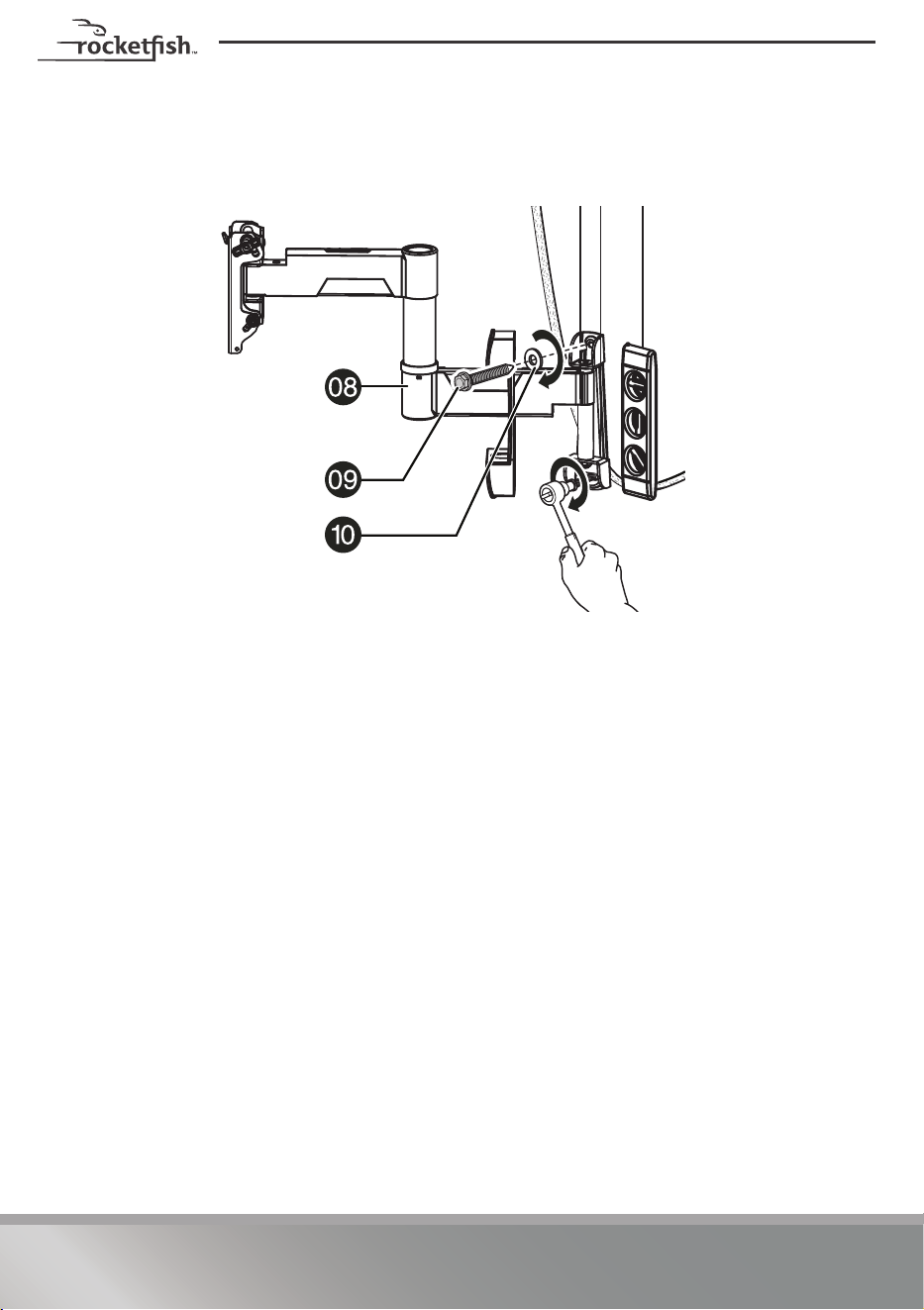
5 Align the TV arm assembly (08) with the pilot holes, insert the lag screws (09)
through washers (10) and into the holes in the wall plate, then tighten the lag
screws only until they are firm against the wall plate.
CAUTION: Avoid potential injuries or property damage! DO NOT over-tighten the lag screws
(09).

17
RF-HTMF19
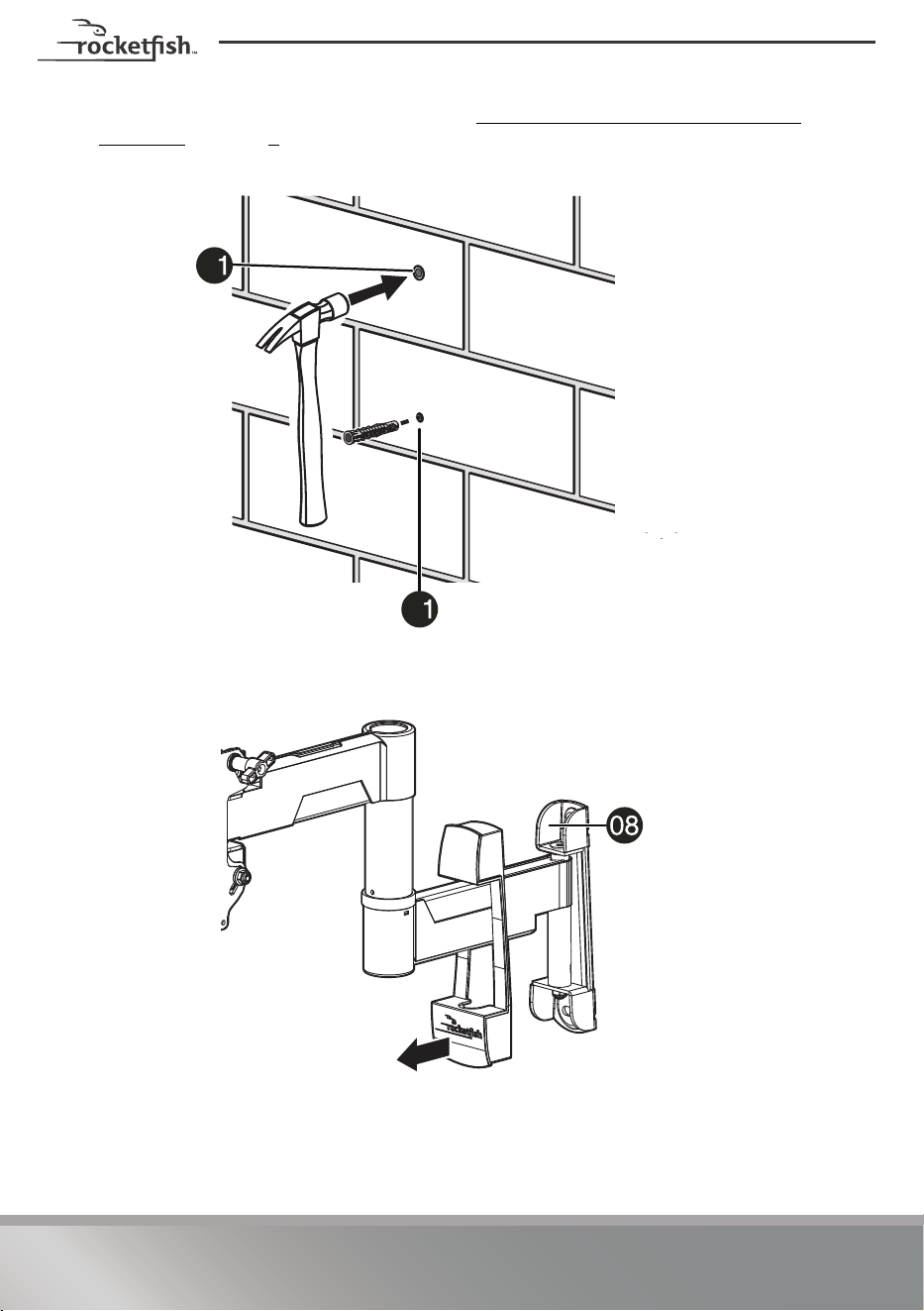
STEP 6 - Option 2: Install on a solid concrete or concrete
block wall
CAUTION: To prevent property damage or personal injury, never drill into the mortar between
the blocks. Mount the wall plate directly onto the concrete surface.
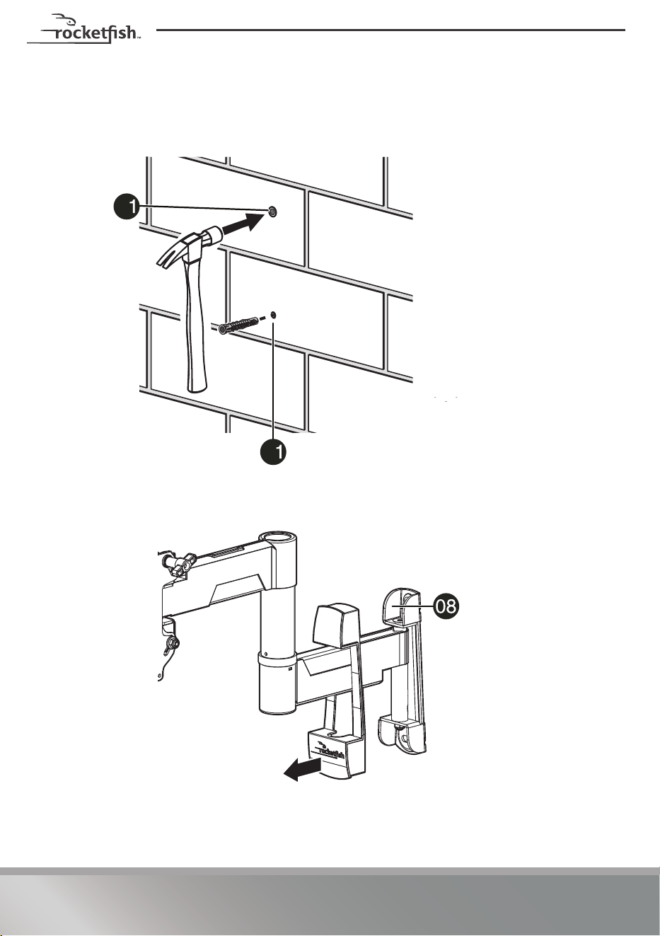
1 Align the center of the mounting template (07) at the height you determined in
the previous step and make sure that it is level. Tape the mounting template to
the wall, then drill pilot holes to a depth of 3 in. (76 mm) using a 3/8 in. (10 mm)
diameter masonry drill bit, then remove the mounting template.
Note: Mount the TV arm assembly (08) directly onto the concrete surface (no wall
covering).
Minimum solid concrete thickness: 8 in. (20.3 cm).
Minimum concrete block size: 8 × 8 × 16 in. (20.3 × 20.3 × 40.6 cm).
You’ll need
3/8 in (10 mm)
3 in. (76 mm)
Hammer
C1 Concrete
anchors (2)
09 Lag screw (2)
Drill
3/8" masonry
drill bit
1/2" socket
wrench
07 Mounting
template
Tape
08 TV arm assembly
Level
10 Washer (2)
Note: The Concrete Installation Kit
(CMK1) is not included. Contact
Customer Service to request it.
19
RF-HTMF19
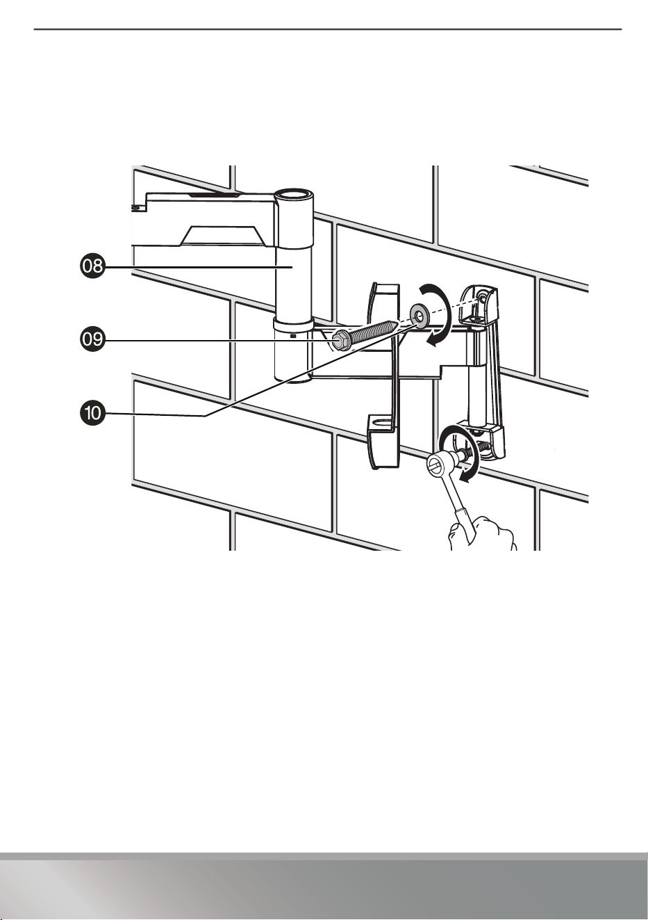
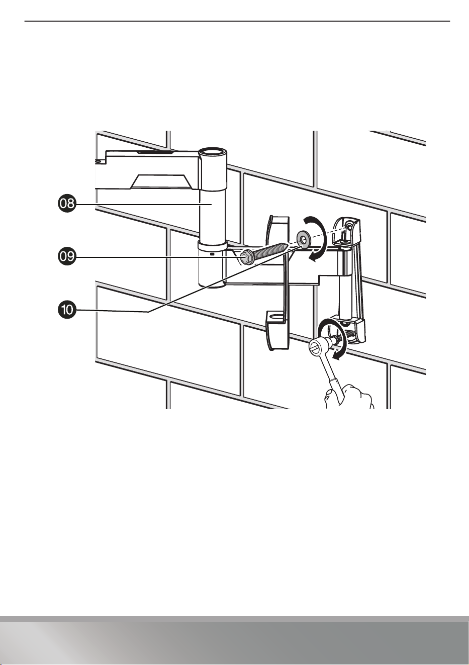
4 Align the TV arm assembly (
08) with the anchors (C1), insert the lag screws (09)
through the washers (
10) and into the holes in the wall plate, then tighten the
lag screws only until they are firm against the wall plate.
CAUTION: Avoid potential injuries or property damage! DO NOT over-tighten the lag
screws (09).

20
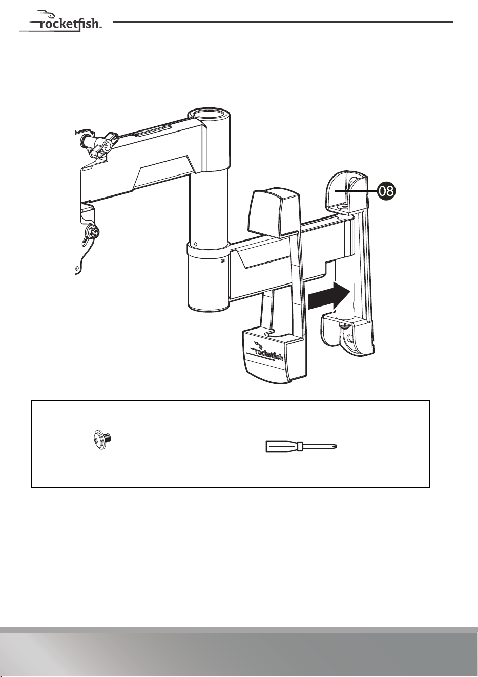
STEP 7 - Attach the TV
1 Move the cover in to cover the arm assembly wall plate, then extend the arm out
from the wall.
You’ll need
11 Locking
screw (1)
Phillips screwdriver

21
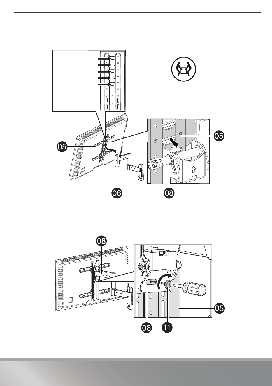
RF-HTMF19
2 Hang your TV on the arm assembly. Select the height you want by choosing the
appropriate slot in the vertical TV bracket.
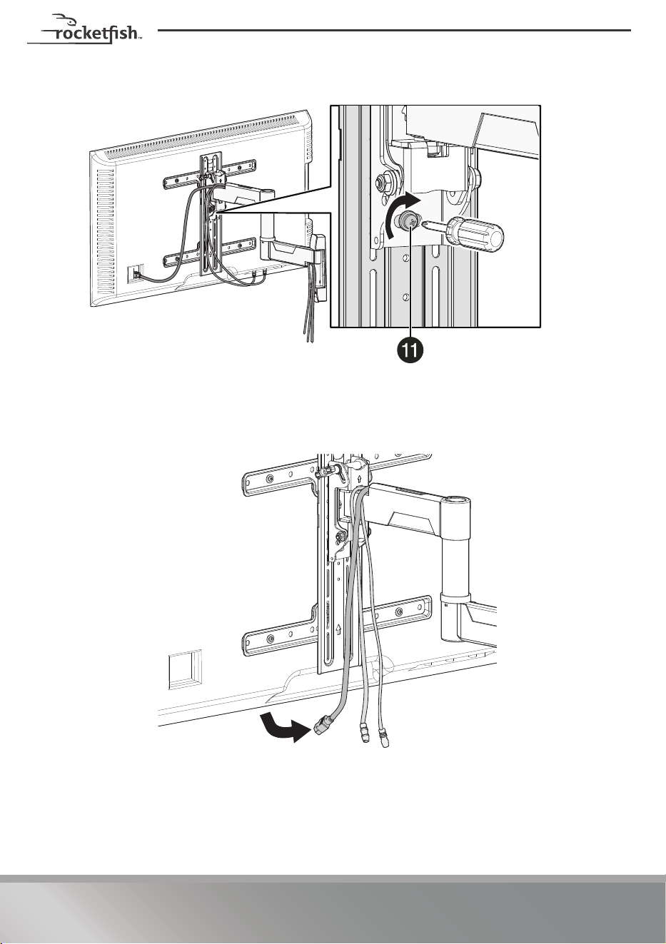
3 Secure your TV to the TV arm assembly with the locking screw (11).
CAUTION: To avoid possible personal injury or equipment damage, you must use the locking
screw (11) to secure your TV to the TV arm assembly.
HEAVY! You may
need assistance
with this step.
Select the
height you want
22
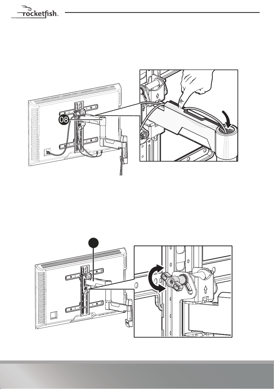
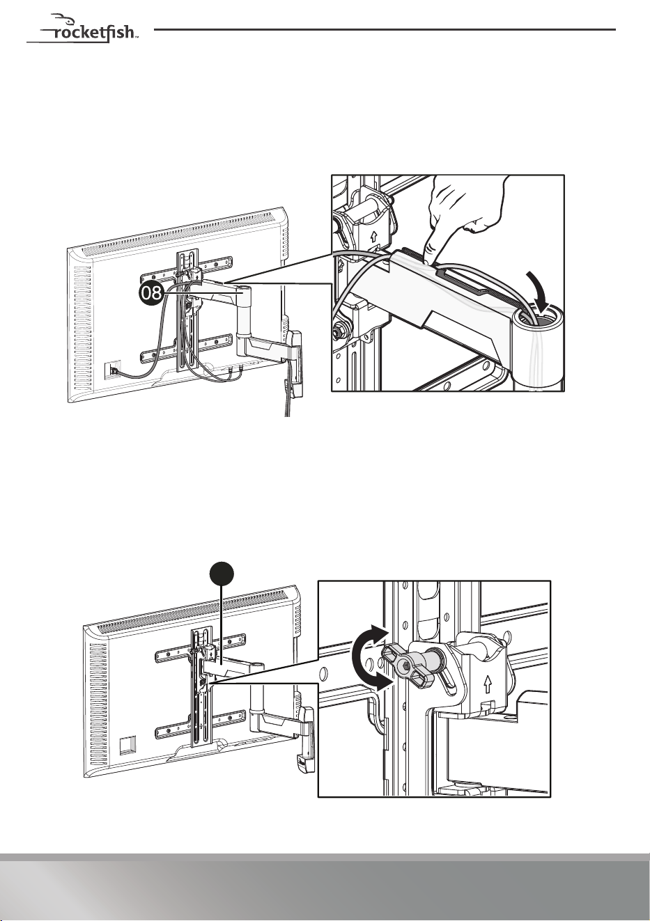
STEP 8 - Manage cables
• Fully extend the TV arm assembly (08) to provide enough slack, then route
cables along the arms, inserting them into the channels on the arms to provide
a clean look to your installation.
STEP 9 - Adjust the tilt
Note: After your TV is in place, tighten the tilt tension knob to prevent unwanted
movement. Additional tension can be applied by using a 3/16 in. hex key (not
provided).
• Loosen the tension knob with your fingers, adjust the tilt angle, then tighten
the knob to keep your TV in place.
08

23
RF-HTMF19
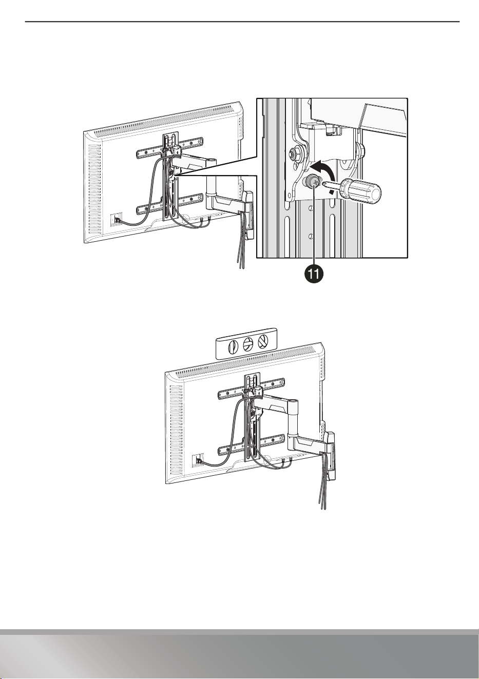
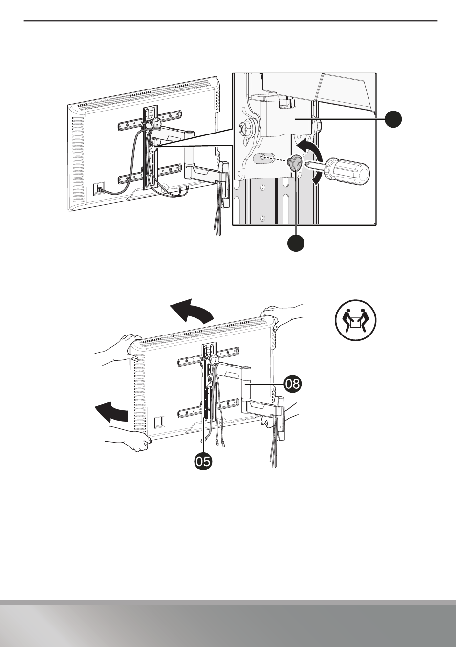
STEP 10 - Adjust the level
1 Loosen the locking screw (11) with a Phillips screwdriver.
2 Level your TV.

24
3 Retighten the locking screw (11) with a Phillips screwdriver.
Remove your TV from the wall mount
1 Disconnect all cables.

25
RF-HTMF19
2 Remove the locking screw (
11) with a Phillips screwdriver.
3 Lift your TV off the arm assembly.
For customer service, call: 1-800-620-2790 (U.S. and Canada)
11
08
HEAVY! You may
need assistance
with this step.

26
LIFETIME LIMITED WARRANTY
Definitions:
The Distributor* of Rocketfish branded products warrants to you, the original purchaser of this new
Rocketfish-branded product (“Product”), that the Product shall be free of defects in the original
manufacturer of the material or workmanship for the Warranty Period.
For this warranty to apply, your Product must be purchased in the United States or Canada from a Best Buy
branded retail store or online at www.bestbuy.com
or www.bestbuy.ca and is packaged with this warranty
statement.
How long does the coverage last?
The Warranty Period lasts for the useful life of the Product beginning on the date you purchased the
Product. Your purchase date is printed on the receipt you received with the Product. In the event the
Distributor ceases to sell the covered Rocketfish-branded product, this Limited Lifetime Warranty shall
terminate for that product and there shall be no repair or replacement of the Product.
What does this warranty cover?
During the Warranty Period, if the original manufacture of the material or workmanship of the Product is
determined to be defective by an authorized Rocketfish repair center or store personnel, Rocketfish will (at
its sole option): (1) repair the Product with new or rebuilt parts; or (2) replace the Product at no charge with
new or rebuilt comparable products or parts. Products and parts replaced under this warranty become the
property of Rocketfish and are not returned to you. If service of Products or parts are required after the
Warranty Period expires, you must pay all labor and parts charges. This warranty lasts as long as you own
your Rocketfish Product during the Warranty Period. Warranty coverage terminates if you sell or otherwise
transfer the Product.
How to obtain warranty service?
If you purchased the Product at a Best Buy retail store location or from a Best Buy online website
(www.bestbuy.com or www.bestbuy.ca), please take your original receipt and the Product to any Best Buy
store. Make sure that you place the Product in its original packaging or packaging that provides the same
amount of protection as the original packaging.
To obtain warranty service, in the United States and Canada call 1-800-620-2790. Call agents may diagnose
and correct the issue over the phone.
Where is the warranty valid?
This warranty is valid only in the United States and Canada at Best Buy branded retail stores or websites to
the original purchaser of the product in the country where the original purchase was made.
What does the warranty not cover?
This warranty does not cover:
• Customer instruction/education
• Installation
• Set up adjustments
• Cosmetic damage
• Damage due to weather, lightning, and other acts of God, such as power surges
• Accidental damage
•Misuse
•Abuse

27
RF-HTMF19
• Negligence
• Commercial purposes/use, including but not limited to use in a place of business or in communal
areas of a multiple dwelling condominium or apartment complex, or otherwise used in a place of
other than a private home.
• Unauthorized modification of any part of the Product, including the antenna
• Display panel damaged by static (non-moving) images applied for lengthy periods (burn-in).
• Damage due to incorrect operation or maintenance
• Connection to an incorrect voltage or power supply
• Attempted repair by any person not authorized by Rocketfish to service the Product
• Products sold “as is” or “with all faults”
• Consumables, including but not limited to batteries (i.e. AA, AAA, C etc.)
• Products where the factory applied serial number has been altered or removed
• Loss or Theft of this product or any part of the product
• Display panels containing up to three (3) pixel failures (dots that are dark or incorrectly
illuminated) grouped in an area smaller than one tenth (1/10) of the display size or up to five (5)
pixel failures throughout the display. (Pixel based displays may contain a limited number of pixels
that may not function normally.)
• Failures or Damage caused by any contact including but not limited to liquids, gels or pastes.
REPAIR REPLACEMENT AS PROVIDED UNDER THIS WARRANTY IS YOUR EXCLUSIVE REMEDY FOR BREACH
OF WARRANTY. ROCKETFISH SHALL NOT BE LIABLE FOR ANY INCIDENTAL OR CONSEQUENTIAL DAMAGES
FOR THE BREACH OF ANY EXPRESS OR IMPLIED WARRANTY ON THIS PRODUCT, INCLUDING, BUT NOT
LIMITED TO, LOST DATA, LOSS OF USE OF YOUR PRODUCT, LOST BUSINESS OR LOST PROFITS. ROCKETFISH
PRODUCTS MAKES NO OTHER EXPRESS WARRANTIES WITH RESPECT TO THE PRODUCT, ALL EXPRESS AND
IMPLIED WARRANTIES FOR THE PRODUCT, INCLUDING BUT NOT LIMITED TO ANY IMPLIED WARRANTIES OF
AND CONDITIONS OF MERCHANTABILITY AND FITNESS FOR A PARTICULAR PURPOSE, ARE LIMITED IN
DURATION TO THE WARRANTY PERIOD SET FORTH ABOVE AND NO WARRANTIES, WHETHER EXPRESS OR
IMPLIED, WILL APPLY AFTER THE WARRANTY PERIOD. SOME STATES, PROVINCES AND JURISDICTIONS DO
NOT ALLOW LIMITATIONS ON HOW LONG AN IMPLIED WARRANTY LASTS, SO THE ABOVE LIMITATION MAY
NOT APPLY TO YOU. THIS WARRANTY GIVES YOU SPECIFIC LEGAL RIGHTS, AND YOU MAY ALSO HAVE
OTHER RIGHTS, WHICH VARY FROM STATE TO STATE OR PROVINCE TO PROVINCE.
Contact Rocketfish:
1-800-620-2790
www.rocketfishproducts.com
Rocketfish is a trademark of Best Buy and its affiliated companies.
*Distributed by Best Buy Purchasing, LLC
7601 Penn Ave South, Richfield, MN 55423 U.S.A.
©2022 Best Buy. All rights reserved.

28
ESPAÑOL
Introducción
Felicitaciones por su compra de un producto de alta calidad de Rocketfish. Su
RF-HTMF19 representa el más moderno diseño de montaje en pared para televisor y
está diseñado para brindar un rendimiento confiable y sin problemas.
INSTRUCCIONES IMPORTANTES DE
SEGURIDAD
GUARDE ESTAS INSTRUCCIONES
• Este producto está diseñado ÚNICAMENTE para ser instalado en vigas de madera,
concreto sólido o bloques de concreto.
• NO LO INSTALE SOLAMENTE EN UN PANEL DE YESO - EL PANEL DE YESO SOLO NO
AGUANTARÁ EL PESO DE SU TELEVISOR.
• Este producto está diseñado ÚNICAMENTE PARA USO EN INTERIORES.
• La pared debe ser capaz de soportar cinco veces el peso del televisor, y el montaje de
pared.
• No utilice este producto con cualquier propósito que no esté implícitamente
especificado por el fabricante.
• El fabricante no se hace responsable por daños o lesiones causadas por un ensamblaje
o uso incorrecto.
• Una instalación inadecuada podría causar daños materiales o lesiones personales. Si no
comprende estas instrucciones, o tiene dudas sobre la seguridad de la instalación,
póngase en contacto con el Servicio al cliente o llame a un contratista calificado
Rocketfish no se hace responsable por daños o lesiones causadas por una instalación o
uso incorrecto.
• El peso de su televisor y accesorios no debe exceder 24.9 kg (55 lb).
• Este producto contiene piezas pequeñas que representan un peligro de asfixia si se
tragan. ¡Mantenga estas piezas alejadas de los niños!
Especificaciones
• Peso máximo del televisor: 24.9 kg (55 lb)
• Tamaño de pantalla: de 81.3 a 139.7 cm (32 a 55 pulg.) en diagonal
• Dimensiones totales (Alto × Ancho): tiras de 43.6 cm × 43.6 cm (17.2 × 17.2 pulg.)
• Peso del montaje en pared: 3.31 kg (7.3 lb)
• Patrones VESA: 75 × 75 hasta 400 × 400 (con todos los tamaños comunes entre
ellos)
• Para el servicio al cliente llame al: 1-800-620-2790
29
RF-HTMF19
Dimensiones
48.8 cm
(19.2 pulg.)
90°
90°
15°
Abajo
5°
Arriba
5.7 cm (2.2 pulg.)
Vista superior
Vista lateral/inclinado
Vista superior extendido
43.6 cm (17.2 pulg.)
43.6 cm (17.2 pulg.)
1.6 cm
(0.6 pulg.)
Línea central vertical
Dimensiones para el montaje
(ver también paso 5)
30
Herramientas requeridas
Necesitará las siguientes herramientas para ensamblar su montaje de pared nuevo
para el televisor:
Detector de
vigas de borde a
borde
Lápiz Nivel
Llave de tubos con tubo de 1/2
pulg. (13 mm) o llave ajustable
Cinta métrica Taladro
Cinta
adhesiva
Martillo
Pared con vigas de madera
Hormigón o pared de bloques de hormigón
Broca de taladro
de pared de 10
mm (3/8 pulg.)
Broca de taladro
para madera de 5.5
mm (7/32 pulg.)
Punzón
Destornillador Phillips
31
RF-HTMF19
Contenido del paquete
Asegúrese de que tenga todos los herrajes necesarios para instalar su montaje de
pared nuevo para el televisor:
08 Montaje del brazo del
televisor
07 Plantilla de montaje
04 Soportes de televisor
horizontales (2)
05 Soporte de televisor
vertical
32
Ferretería para el televisor
N.°
Ferretería
N.
°
N.°
Ferretería
N.
°
01
4
02
4
4
03
4
4
4
06
4
09
2
10
2
11
1
Tornillo M4 de 12 mm
Arandela M4
Tornillo M4 de 35 mm
Arandela
M6/M8
Tornillo M6 de
12 mm
Espaciador
(2.5 mm)
Tornillo M6 de
20 mm
Espaciador (5 mm)
Tornillo M6 de 35 mm
Espaciador
(22 mm)
Tornillo M8 de
16 mm
Tornillo del soporte
del televisor
M5 × 8.5 mm
Tornillo M8 de
25 mm
Perno de retraso de 5/16 ×
2 3/4 pulg.
Tornillo M8 de 35 mm
Arandela de 5/16
pulg.
Tornillo M8 de 50 mm
Tornillo de bloqueo
M5 x 6 mm
33
RF-HTMF19
Kit de instalación para concreto CMK1 (no se incluye)
Contacte el servicio al cliente al 1-800-620-2790 para tener estas partes adicionales
enviadas directamente a usted.
N.°
Ferretería
N.
°
C1 2
Anclajes para concreto
(Fischer UX10 x 60R)
34
Instrucciones de instalación
PASO 1 - Determine si su televisor tiene una parte
posterior plana, irregular u obstruida.
1 Coloque cuidadosamente el televisor con la pantalla hacia abajo, sobre una
superficie acolchonada y limpia para proteger la pantalla de daños y rayones.
2 Si su televisor tiene una base para mesa instalada, remueva la base. Refiérase a
los documentos que vienen con su televisor para obtener instrucciones.
3 Ponga temporalmente los soportes horizontales (
04) en la parte posterior de su
televisor.
4 Alinee los agujeros de tornillos en los soportes con los agujeros de tornillo de
montaje en su televisor.
5 Determine que tipo de parte posterior su televisor tiene:
• Panel posterior plano: Los soportes están al ras de la parte posterior de su
televisor y no bloquean ninguna toma. No necesitará espaciadores al
ensamblar el soporte de montaje en pared.
• Parte posterior obstruida: El soporte bloquea cualquiera de las tomas en la
parte posterior de su televisor. Necesitará espaciadores de 2.5 mm, 5 mm o 22
mm (03) al ensamblar el soporte de montaje de pared.
• Parte posterior con forma irregular: Hay un espacio entre los soportes y
alguna parte de la parte posterior de su televisor. Necesitará espaciadores de
2.5 mm, 5 mm o 22 mm (03) al ensamblar el soporte de montaje de pared.
6 Remueva los soportes.
35
RF-HTMF19
PASO 2 - Selección de los tornillos, arandelas y
espaciadores
1 Seleccione los herrajes para su televisor (tornillos, arandelas y espaciadores).
Ciertos televisores vienen con ferretería de montaje incluida. (si los tornillos
vinieron con su televisor, casi siempre están en los agujeros de la parte posterior
del televisor). Si no conoce la longitud y el diámetro correcto de los tornillos de
montaje que su televisor requiere, pruebe tamaños diferentes enroscándolos
manualmente.
Seleccione los tornillos que se ajusten:
Seleccione las arandelas M4 (02) para los tornillos tipo M4 o las arandelas M6/M8
(02) para los tornillos tipo M6 o M8. Para televisores con una parte posterior
irregular u obstruida, utilice los espaciadores de 2.5 mm, 5 mm o
22 mm (
03).
CUIDADO: Para evitar posibles lesiones personales y daños materiales,
asegúrese de que los tornillos tengan una rosca adecuada para asegurar
los soportes a su televisor. Si encuentra resistencia, deténgase
inmediatamente y póngase en contacto con el Servicio al cliente. Utilice la
combinación de tornillo y espaciador más corta para acomodar su televisor. El uso
de herrajes demasiado largos puede dañar su televisor. Sin embargo, el uso de un
tornillo que es demasiado corto puede causar la caída del televisor del montaje.
2 Remueva los tornillos.
Tornillos M4 de 12 mm (01) Tornillos M8 de 16 mm (01)
Tornillos M4 de 35 mm (01) Tornillos M8 de 25 mm (01)
Tornillos M6 de 12 mm (01) Tornillos M8 de 35 mm (01)
Tornillos M6 de 20 mm (01) Tornillos M8 de 50 mm (
01)
Tornillos M6 de 35 mm (01)
El tornillo es
demasiado largo
El tornillo encaja
correctamente
El tornillo es
demasiado corto
36
PASO 3: Colocación de los soportes horizontales en su
televisor
CUIDADO: Para evitar lesiones personales o daños materiales, no utilice
herramientas eléctricas.
1 Alinee los agujeros que identificó en el soportes horizontales (04) con los
agujeros para los tornillos en la parte posterior del televisor.
2 Coloque las arandelas (
02) sobre los agujeros en los soportes que se alinean con
los agujeros de tornillos en la parte posterior del televisor e inserte los tornillos
que selecciono en el PASO 2 (
01) a través de las arandelas. Asegúrese de que los
soportes estén a nivel.
3 Agregue espaciadores (03) si determinó que los espaciadores son necesarios en
el PASO 1.
4 Apriete los tornillos hasta que estén firmemente contra los soportes. No apriete
demasiado.
37
RF-HTMF19
Necesitará
02 Arandelas (4)
01 Tornillos (4)
O
04 Soportes de
televisor
horizontales (2)
O
O
O
Destornillador Phillips
O
O
Espaciadores 03 (4)
38
PASO 4: Colocación del soporte horizontal a su televisor
CUIDADO: Para evitar lesiones personales o daños materiales, no utilice
herramientas eléctricas.
1 Coloque el soporte vertical (05) encima de los soportes horizontales (04).
Asegúrese de que el soporte esté en el centro.
2 Fije el soporte vertical (
05) a los soportes horizontales con los tornillos del
soporte del televisor (
06). Apriete los tornillos hasta que estén firmemente
contra los soportes verticales. No apriete demasiado.
Necesitará
06 Tornillos del
soporte del
televisor (4)
Destornillador
Phillips
05 Soporte de televisor vertical (1)
39
RF-HTMF19
PASO 5 - Determine la ubicación del montaje en pared
Nota: Su televisor debe estar lo suficientemente alto para que sus ojos estén a la
altura de la mitad de la pantalla desde una posición de sentado (normalmente, a
una distancia de 40 a 60 pulgadas del suelo).
Para información más detallada en como determinar donde taladrar los agujeros,
visite el sitio height-finder (Detector de altura) en línea en:
http://bestbuy.selectionassistant.com/heightfinder/#!step1
El centro del juego del brazo del televisor (08) NO es el mismo que el centro del
soporte vertical del televisor (05). El centro del soporte vertical del televisor está más
alto que el centro del juego del brazo del televisor. Cuando se utiliza la ranura central
del soporte de televisor vertical, el orificio superior del juego del brazo del televisor
estará 0.6 pulg. por debajo del centro del soporte de televisor vertical y del punto
central de su televisor.
Los patrones de montaje VESA no están centrados en todos los televisores. Deberá
tener en cuenta la ubicación del patrón VESA a la hora de determinar la altura del
juego del brazo del televisor.
43.6 cm (17.2 pulg.)
43.6 cm (17.2 pulg.)
1.6 cm (0.6
pulg.)
Línea central vertical
40
PASO 6 - Opción 1: Instale en una pared con viga de
madera
1 Localice la viga, luego verifique el centro de la viga con un detector de vigas de
borde a borde o la pared.
Cuidado:
El panel de yeso que cubra la pared no debe exceder 5/8 pulg. (1.6 cm).
Tamaño mínimo de la viga de madera: nominal 5.1 × 10.2 cm (2 × 4 pulg.) actual 3.8 × 8.9 cm (1
1/2 × 3 1/2 pulg.).
Necesitará
Detector de
vigas de borde
a borde
09 Perno de retraso (2)
Taladro
Broca de taladro para madera
de 7/32 pulg.
Llave de tubos de 1/2 pulg.
07 Plantilla de
montaje
Cinta adhesiva
08 Montaje del brazo
del televisor
Nivel
10 Arandela (2) Punzón

41
RF-HTMF19
2 Alinee en centro de la plantilla de montaje (07) a la altura que determinó en el
paso anterior y asegúrese de que esté a nivel. Pegue con cinta adhesiva la
plantilla a la pared.
3 Taladre dos agujeros piloto a través de la plantilla de montaje a una profundidad
de 70 mm (2 3/4 pulg.) utilizando una broca de 5.5 mm (7/32 pulg.) de diámetro
y luego retire la plantilla de montaje.
4 Aleje la cubierta de la placa de pared del juego del brazo.
3/4
5.5 mm
(7/32
pulg.)
5.5 mm (7/32 pulg.)
70 mm (2 3/4 pulg.)
08
42
5 Alinee el brazo de montaje del televisor (08) con los agujeros pilotos, inserte los
pernos de retraso (09) a través de las arandelas (10) y en los agujeros del
ensamblado de la placa para pared y luego apriete los pernos de retraso hasta
que se encuentren firmemente contra la placa para pared.
CUIDADO: ¡Evite lesiones potenciales o daños materiales! NO apriete excesivamente los
pernos de retraso (09).
43
RF-HTMF19
PASO 6 - Opción 2: Instalación en una pared de concreto
sólido o de bloques de concreto
CUIDADO: Para evitar daños materiales o lesiones a personas, nunca taladre en la argamasa
entre los bloques. Monte la placa de pared directamente sobre la superficie de concreto.
1 Alinee en centro de la plantilla de montaje (07) a la altura que determinó en el
paso anterior y asegúrese de que esté a nivel. Taladre el agujero piloto a una
profundidad de 76 mm (3 pulg.) usando una broca de taladro de 10 mm (3/8
pulg.) de diámetro usando una broca de taladro para concreto de 10 mm (3/8
pulg.) de diámetro.
Nota: Monte el juego de brazos del televisor (08) directamente sobre la superficie de
concreto (no el revestimiento de la pared).
Grosor mínimo del concreto sólido: 20.3 cm (8 pulg.).
Tamaño mínimo del bloque de concreto: 20.3 × 20.3 × 40.6 cm (8 × 8 × 16 pulg.).
Necesitará
10 mm (3/8 pulg.)
76 mm (3 pulg.)
Martillo
Anclajes para
concreto C1 (2)
09 Perno de retraso
(2)
Taladro
Broca de taladro
de concreto de
3/8 pulg.
Llave de tubos
de 1/2 pulg.
07 Plantilla de
montaje
Cinta adhesiva
08 Montaje del brazo
del televisor
Nivel
10 Arandela (2)
Nota: Kit de instalación de hormigón
MK1 (no incluido) Póngase en contacto
con el Servicio de atención al cliente
para solicitarlo.
44
2 Inserte los anclajes de pared para concreto (C1) (refiérase a Concrete Installation
Kit CMK1 (not included) en la página 8) en los agujeros guías y con un martillo
asegúrese de que los anclajes estén al ras con la superficie de concreto.
3 Mueva la cubierta de la placa de pared hacia afuera, lejos de la placa de pared.
C
C
45
RF-HTMF19
4 Alinee el brazo de montaje del televisor (
08) con los anclajes (C1), inserte los
pernos de retraso (
09) a través de las arandelas (10) y en los agujeros del
ensamblado de la placa para pared y luego apriete los pernos de retraso hasta
que se encuentren firmemente contra la placa para pared.
CUIDADO: ¡Evite lesiones potenciales o daños materiales! NO apriete excesivamente los
pernos de retraso (09).
46
PASO 7: Coloque el televisor
1 Mueva la cubierta hacia adentro para cubrir la placa de pared del juego del
brazo, luego extienda el brazo hacia afuera de la pared.
Necesitará
11 Tornillo de
bloqueo (1)
Destornillador
Phillips
47
RF-HTMF19
2 Cuelgue su televisor en el juego de brazos. Seleccione la altura que desee
eligiendo la ranura adecuada en el soporte vertical del televisor.
3 Fije su televisor al juego del brazo del televisor con el tornillo de bloqueo (11).
CUIDADO: Para evitar posibles lesiones personales o daños al equipo, debe utilizar el tornillo
de bloqueo (11) para fijar el televisor al conjunto del brazo del televisor.
¡PESADO! Se
puede que
necesitará ayuda
con este paso.
Seleccione la
altura que desee.
48
Paso 8 - Organización de los cables
• Extienda completamente el juego del brazo del televisor (08) para que quede
lo suficientemente flojo, luego pase los cables a lo largo de los brazos e
introdúzcalos en los canales de los brazos para dar un aspecto limpio a su
instalación.
PASO 9: Ajuste de la inclinación
Nota: Después que el televisor esté en su lugar, apriete la perilla de la tensión de
inclinación para evitar movimientos no deseados. Se puede aplicar una tensión
adicional utilizando una llave hexagonal de 3/16 pulg. (no suministrada).
• Afloje el botón de tensión con los dedos, ajuste el ángulo de inclinación y
apriete el botón para mantener el televisor en su sitio.
08
49
RF-HTMF19
PASO 10 - Ajuste el nivel
1 Afloje el tornillo de bloqueo (11) con un destornillador Phillips.
2 Nivele su televisor.
50
3 Vuelva a apretar el tornillo de bloqueo (11) con un destornillador Phillips.
Retire su televisor del montaje en pared.
1 Desconecte todos los cables
51
RF-HTMF19
2 Retire el tornillo de bloqueo (
11) con un destornillador Phillips.
3 Levante el televisor del juego del brazo.
11
08
¡PESADO! Se
puede que
necesitará ayuda
con este paso.

52
Para el servicio al cliente llame al: 1-800-620-2790 (EE.UU. y
Canadá)

53
RF-HTMF19
GARANTÍA LIMITADA DE POR VIDA
Descripción:
El distribuidor* de los productos de la marca Rocketfish le garantiza a usted, el comprador original de este
producto nuevo de la marca Rocketfish (“Producto”), que el Producto estará libre de defectos de material o
de mano de obra en su fabricación original durante el Período de Garantía.
Para que esta garantía se aplique, su Producto tiene que haberse comprado en los Estados Unidos o en
Canadá con un detallista de la marca Best Buy o en línea en los sitios www.bestbuy.com
o www.bestbuy.ca
y empacado con esta declaración de garantía.
¿Cuánto dura la garantía?
El Período de Garantía dura toda la vida útil del Producto a partir de la fecha en que compró el Producto. La
fecha de compra se encuentra impresa en el recibo que recibió con el Producto. En el caso de que el
Distribuidor deje de vender el producto de la marca Rocketfish garantizado, esta garantía limitada de por
vida se terminará para este producto y no se podrá obtener reparación ni reemplazo del Producto.
¿Qué es lo que cubre esta garantía?
Durante el Período de Garantía, si un centro de reparación autorizado de Rocketfish concluye que la
fabricación original del material o la mano de obra del Producto se encuentran defectuosos Rocketfish
(cómo su opción exclusiva): (1) reparará el Producto con repuestos nuevos o reconstruidos; o (2)
reemplazará el Producto sin costo alguno por un producto nuevo o reconstruido con características
similares. Los Productos y repuestos reemplazados bajo esta garantía se convertirán en propiedad de
Rocketfish y no serán devueltos. Si se requiere la reparación de Productos o partes después de que se
vence el Período de Garantía, usted deberá pagar todos los costos de mano de obra y de repuestos. Esta
estará vigente con tal que usted sea el dueño de su Producto Rocketfish durante el periodo de garantía. La
cobertura de la garantía se anula si usted vende o transfiere el Producto.
¿Cómo se obtiene el servicio de garantía?
Si se compró el Producto en una tienda de Best Buy, o en un sitio Web de Best Buy (www.bestbuy.com o
www.bestbuy.ca), lleve su recibo original y el Producto a cualquier tienda de Best Buy. Asegúrese de volver
a colocar el Producto en su empaque original o en un empaque que provea la misma protección que el
original.
Para obtener servicio de garantía, llame al 1-800-620-2790 en los Estados Unidos y Canadá. Los agentes de
soporte técnico diagnosticarán y corregirán el problema por teléfono.
¿Dónde es válida la garantía?
Esta garantía sólo es válida en los Estados Unidos y Canadá en las tiendas de Best Buy o en sus sitios Web
para el comprador original del producto en el país donde se realizó la compra.
¿Qué es lo que no cubre la garantía?
Esta garantía no cubre:
• Capacitación o instrucción del cliente
•Instalación
• Ajustes de configuración
• Daños cosméticos
• Daños debidos al clima, relámpagos, causas de fuerza mayor, tales como sobretensiones
• Danos accidentales
• Uso inapropiado

54
•Abuso
•Negligencia
• Uso o propósito comercial, incluyendo pero no limitado al uso en centros comerciales o lugares
comunes de un condominio de varios pisos o un edificio de departamentos, o cualquier uso en un
lugar que no sea una casa privada.
• La modificación de alguna parte del Producto, incluyendo la antena
• Un panel de pantalla dañado por la persistencia de imágenes estáticas (sin movimiento),
mostradas por períodos de tiempo extendido (efecto “burn-in”).
• Daño debido al uso o mantenimiento inapropiado
• Conexión a una fuente de voltaje o de alimentación incorrecta
• Intento de reparación por cualquier persona que no sea autorizada por Rocketfish para reparar el
Producto
• Productos vendidos “tal cual” (en el estado en que se encuentran) o “con todas sus fallas”
• Consumibles, incluyendo pero no limitado a pilas (tipo AA, AAA, C etc.)
• Productos en los cuales el número de serie asignado en la fábrica ha sido alterado o removido
• Pérdida o robo de este producto o cualquier parte de sus componentes
• Las pantallas con hasta tres (3) pixels defectuosos (puntos oscuros o incorrectamente iluminados)
agrupados en una superficie más pequeña que la décima parte (1/10) del tamaño de la pantalla ni
hasta cinco (5) pixels defectuosos en toda la superficie de la pantalla. (Las pantallas basadas en
píxeles pueden contener un número limitado de píxeles que pueden no funcionar normalmente).
• Los defectos o daños causados cómo resultado de cualquier contacto, sin limitarse a líquidos, geles
o pastas.
EL REEMPLAZO O LA REPARACIÓN ESTIPULADOS BAJO ESTA GARANTÍA SON SU RECURSO EXCLUSIVO POR
CUALQUIER VIOLACIÓN DE LA GARANTÍA. ROCKETFISH NO SERÁ RESPONSABLE POR DAÑOS
INCIDENTALES O CONSECUENTES DEBIDO AL INCUMPLIMIENTO DE CUALQUIER GARANTÍA EXPRESA O
IMPLÍCITA RELACIONADA CON ESTE PRODUCTO, INCLUYENDO PERO SIN LIMITARSE A ELLO, LA PÉRDIDA
DE DATOS, LA IMPOSIBILIDAD DE USO DE SU PRODUCTO, LA PÉRDIDA DE NEGOCIOS O DE GANANCIAS.
ROCKETFISH PRODUCTS NO OFRECE NINGUNA OTRA GARANTÍA EXPRESA E IMPLÍCITA RELACIONADA
CON ESTE PRODUCTO, INCLUYENDO PERO SIN LIMITARSE A, CUALQUIER GARANTÍA IMPLÍCITA Y
CONDICIONES DE COMERCIALIZACIÓN E IDONEIDAD PARA UN USO PARTICULAR, ESTÁN LIMITADAS EN
DURACIÓN AL PERÍODO DE GARANTÍA DECLARADO ANTERIORMENTE Y NINGUNA GARANTÍA YA SEA
EXPRESA O IMPLÍCITA SE APLICARÁ DESPUÉS DEL PERÍODO DE GARANTÍA. ALGUNOS ESTADOS,
PROVINCIAS Y JURISDICCIONES NO PERMITEN RESTRICCIONES EN CUANTO A LA DURACIÓN DE UNA
GARANTÍA IMPLÍCITA, ASÍ QUE LA RESTRICCIÓN ANTERIOR PUEDE NO APLICARSE EN SU CASO. ESTA
GARANTÍA LE DA DERECHOS LEGALES ESPECÍFICOS, Y USTED PUEDE POSEER OTROS DERECHOS QUE
VARÍAN DE ESTADO A ESTADO, O DE PROVINCIA A PROVINCIA.
Comuníquese con Rocketfish:
1-800-620-2790
www.rocketfishproducts.com
Rocketfish es una marca comercial de Best Buy y sus compañías asociadas.
* Distribuido por Best Buy Purchasing, LLC
7601 Penn Ave South, Richfield, MN 55423 U.S.A.
©2022 Best Buy. Todos los derechos reservados.

V1 ENGLISH/ESPAÑOL
22-0247
www.rocketfishproducts.com
1-800-620-2790 (U.S. and Canada)
ROCKETFISH is a trademark of Best Buy and its affiliated companies.
Registered in some countries. Distributed by Best Buy Purchasing, LLC
7601 Penn Ave South, Richfield, MN 55423 U.S.A.
©2022 Best Buy. All rights reserved.
www.rocketfishproducts.com
1-800-620-2790 (EE.UU. y Canadá)
ROCKETFISH es una marca comercial de Best Buy y sus compañías asociadas.
Registrada en ciertos países. Distribuida por Best Buy Purchasing, LLC
7601 Penn Av. South, Richfield, MN 55423 E.U.A.
© 2022 Best Buy. Todos los derechos reservados.
Part # 6907-302059