Perfect Aire, LLC
5151 Belt Line Rd.
Suite 878
Dallas, TX 75254
Distributed by:
844-4PA-AIRE | 844-472-2473
www.perfectaire.us
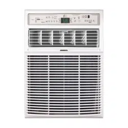
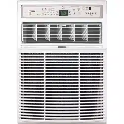
WINDOW
AIR CONDITIONER
FOR MODEL:
3PASC10000
Before using your air conditioner, please
read this manual carefully and keep it for
future reference, along with your receipt.
Specification and performance data is subject to change without notice.
Printed in China
PA/User_3PASC10000/10162017
USER MANUAL
For your own records, please attach a copy of your sales receipt to this manual and complete the following:
Model Number: _____________________________________ Serial Number: _______________________________________
Purchase Date: ____________________________________ Store Purchased: _____________________________________
Installation Date: ___________________________________ Installation Co.: _______________________________________
Installer Name: _____________________________________ Installer Phone No.: ___________________________________
CONSUMER PRODUCT INFORMATION
SAFETY PRECAUTIONS ...................................................................1
IMPORTANT SAFETY INSTRUCTIONS ...........................................3
INSTALLATION INSTRUCTIONS .....................................................4
INSTALLING UNIT IN A SLIDING WINDOW .......................6
INSTALLING UNIT IN A CASEMENT WINDOW ..................9
NORMAL SOUNDS ...........................................................................12
AIR CONDITIONER FEATURES .......................................................12
CARE AND CLEANING ....................................................................15
TROUBLESHOOTING ....................................................................... 16
CONTENTS
This manual provides the information needed for proper use and maintenance
of this air conditioner. Basic preventative care can help extend the life of
this unit. The “Troubleshooting” section in this manual contains a chart with
solutions to the most common problems. Referring to this section may save
time and prevent the need for a service call in the event of a problem.
CAUTIONS
● Contactanauthorizedservicetechnicianforrepairormaintenanceofthisunit.
● Contactaninstallerforinstallationofthisunitifnecessary.
● Theairconditionerisnotintendedforusebyyoungchildrenwithoutadultsupervision.Youngchildrenshouldbe
supervised to ensure that they do not play with the air conditioner.
● Disabledpersonsmayrequireassistancewithsetup.
● Ifthepowercordistobereplaced,replacementworkshouldbeperformedbyauthorizedpersonnelonly.
● Installationandrepairworkmustbeperformedinaccordancewiththenationalwiringstandardsbyauthorized
personnel only.
● Donotoperateyourairconditionerinawetroomsuchasabathroomorlaundryroom.
NOTE:Alltheillustrationsinthismanualareforexplanationpurposesonly.Unitpurchasedmaybeslightlydierent.
Thedesignandspecicationsaresubjecttochangewithoutpriornoticeforproductimprovement.ContactConsumer
Services at 844-472-2473 for details.
1
WARNINGS
Plug in power cord properly. Failuretodosomaycauseelectricshockorredueto
excess heat generation.
DO NOT operate or stop the unit by inserting or pull-
ing out the power plug directly from the wall.
Doingsomaycauseelectricshockorredueto
heat generation.
DO NOT use a damaged power cord.
Doingsomaycauseelectricshockorre.Ifthepower
cord is damaged, it must be replaced by the manufactur-
eroranauthorizedservicecenterorasimilarlyqualied
personinordertoavoidahazard.
DO NOT modify power cord length or share the
outlet with other appliances.
Doingsomaycauseelectricshockorredueto
heat generation.
DO NOT operate with wet hands or in
damp environment.
Doingsomaycauseelectricshock.
DO NOTdirectairowdirectlyatroomoccupants.
This could cause health issues.
Alwaysensureeectivegrounding. Incorrectgroundingmaycauseelectricshock.
DO NOT allow water to run into electric parts.
Doingsomaycausefailureofmachineorelectricshock.
Alwaysinstallcircuitbreakerandadedicated
power circuit.
Incorrectinstallationmaycausereandelectricshock.
Always unplug the unit if strange sounds, smell or
smokecomesfromtheunit.
Failuretodosomaycausereandelectricshock.
DO NOTusethesocketifitislooseordamaged.
Doingsomaycausereandelectricshock.
DO NOT open the unit during operation.
Doingsomaycauseelectricshock.
DO NOTuserearmsnearunit.
Doingsomaycausere.
DO NOT use the power cord close to
heating appliances.
Doingsomaycausereandelectricshock.
DO NOT disassemble, modify, or drill holes into
the air conditioner.
Doingsomaycausefailureandelectricshockandvoid
the manufacturer’s warranty.
Ventilate room before operating air conditioner if
thereisagasleakfromanotherappliancesuchas
a stove.
Failuretodosomaycauseexplosion,reandburns.
DO NOT
usethepowercordnearammablegasor
combustibles,suchasgasoline,benzene,thinner,etc.
Doingsomaycauseanexplosionorre.
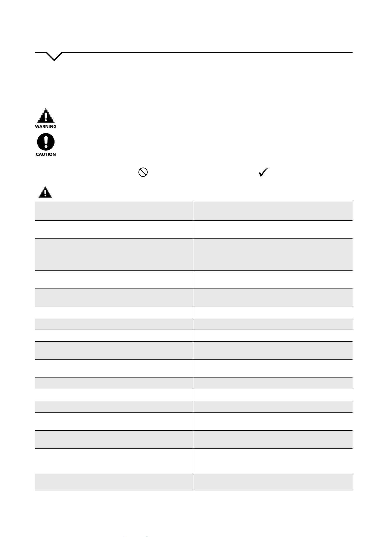
READ SAFETY PRECAUTIONS BEFORE INSTALLATION
Topreventinjurytotheuserorotherpeopleandpropertydamage,thefollowinginstructionsmustbefollowed.
Incorrectoperationduetoignoringofinstructionsmaycauseharmordamage.Theseriousnessisclassiedbythe
following indications.
THIS SYMBOL INDICATES THAT IGNORING INSTRUCTIONS MAY CAUSE
DEATH OR SERIOUS INJURY.
NEVER DO THIS.OTHER SYMBOLS: ALWAYS DO THIS.
THIS SYMBOL INDICATES THAT IGNORING INSTRUCTIONS MAY CAUSE
MODERATE INJURY TO YOUR PERSON, OR DAMAGE TO YOUR UNIT OR
OTHER PROPERTY.
SAFETY PRECAUTIONS
2
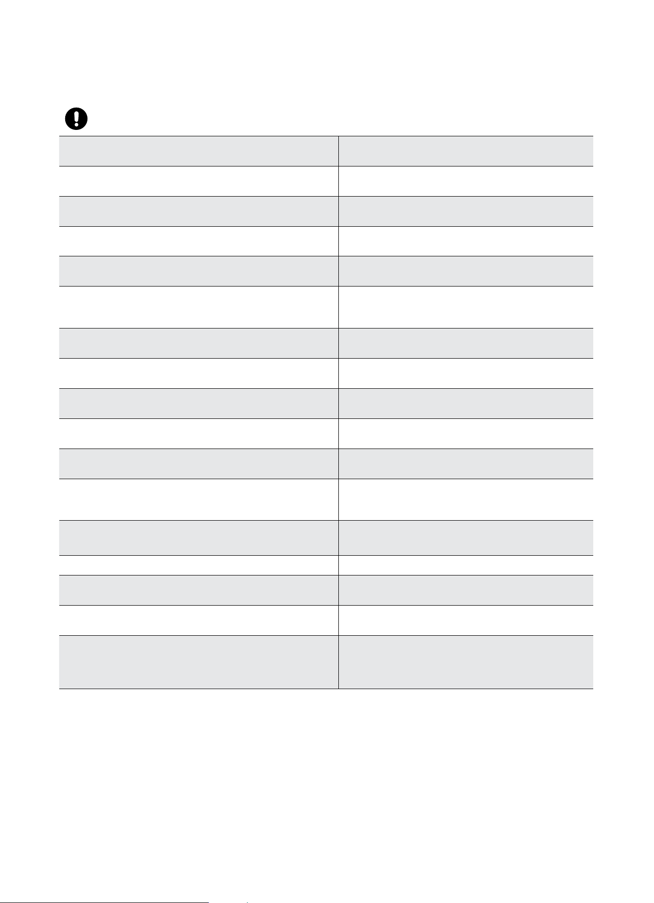
CAUTIONS
Whenremovingairlter,DO NOT touch metal parts of
the unit.
Doingsomaycauseaninjury.
DO NOT clean with water.
Water may enter the unit and degrade the insulation,
causinganelectricshock.
Ensure proper ventilation, especially in rooms with a
stove or other appliances.
Failure to do so may result in an oxygen shortage.
Unitandcircuitbreaker/fusemustbeswitchedOFF
when cleaning.
CleaningunitwhenpowerisONmaycausereand
electricshockandmaycauseaninjury.
DO NOT put a pet or house plant where it will be ex-
posedtodirectairow.
Thiscouldinjurethepetorplant.
Use ONLY as intended. This unit is NOT intended to preserve precision devic-
es,food,pets,plants,andartobjects.Itmaycause
deteriorationofquality,etc.
Stop operation and close the window in severe
storms or hurricanes.
Operationwithwindowsopenmaycausemoistureto
enter the room.
Hold the plug by the head of the power plug when
takingitout.
Failuretodosomaycauseelectricshock
and damage.
If unit will not be used for a long period of time,
unplug or turn OFF main power switch.
Leavingpoweronmaycauseunitfailureorre.
DO NOT place obstacles around air-inlets or inside of
air-outlet.
Obstaclesmaycauseappliancefailureoraccident.
Periodicallycheckinstallationbracketfordamage. Prolonged exposure to outdoor elements may cause
damagetoinstallationbracket,causingunittofall.
Alwaysinsertlter(s)securely.Cleanlter(s)AT LEAST
onceeverytwoweeks.
Operationwithoutsecurelyinstalledltersmaycause
failure.Adirtyltercancausetheunittonotrun
eciently.
Use only a soft cloth to clean the unit. Cleaners or detergents may change the color or
scratch the surface of the unit.
Usecautionwhenunpackingandinstalling. Sharpedgescouldcauseinjury.
NEVERdrinkwaterdrainedfromairconditioner.
Water from unit contains contaminants and could
cause illness.
DO NOTplaceheavyobjectsonthepowercordand
always ensure that the cord is not compressed.
Thereisdangerofreorelectricshock.
If water enters the unit’s electrical components, turn
theunitoatthepoweroutletandswitchothecir-
cuitbreaker.Isolatesupplybytakingthepower-plug
outandcontactaqualiedservicedtechnician.
Thereisdangerofelectricshock.
3
IMPORTANT SAFETY INSTRUCTIONS
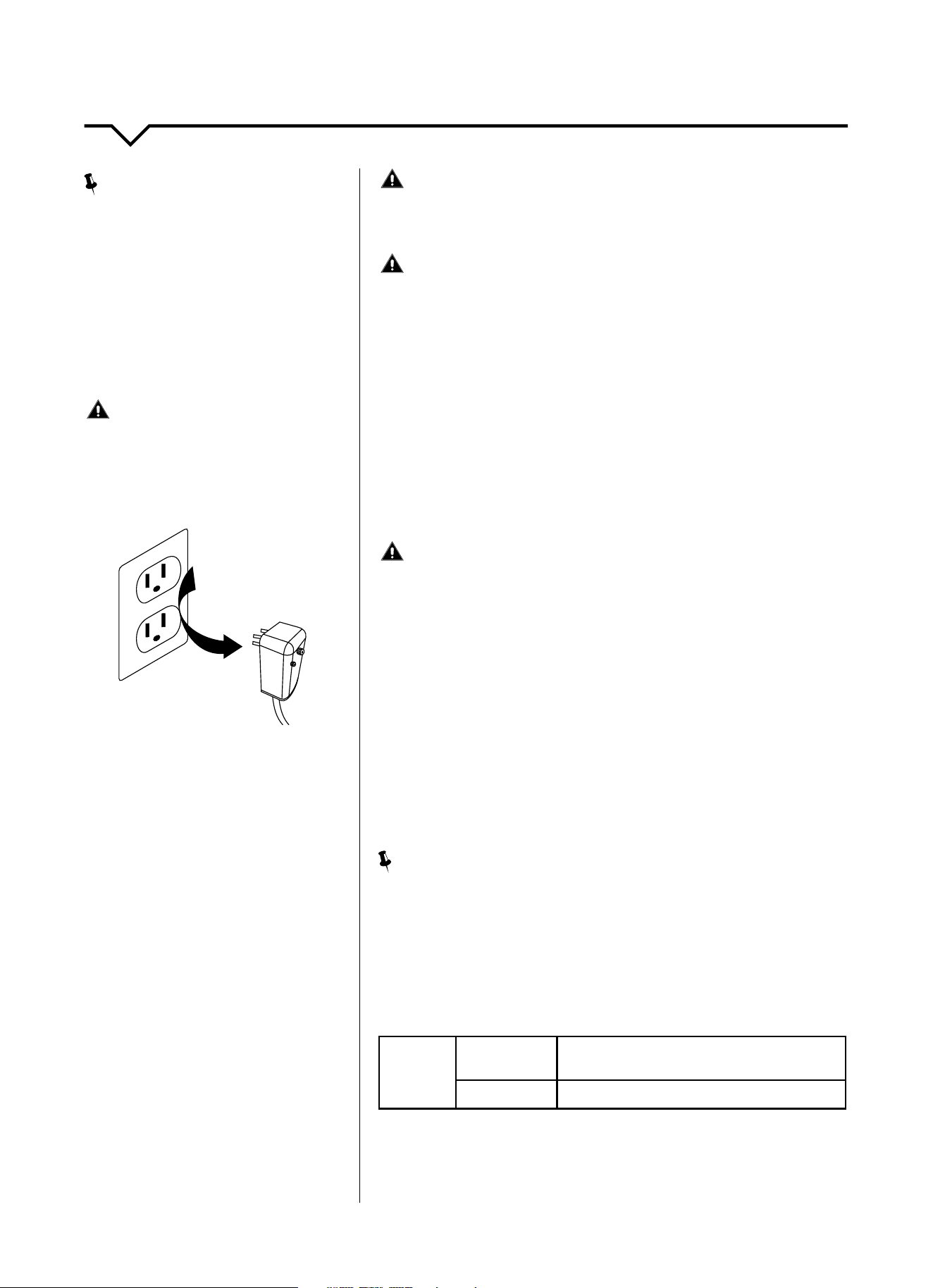
NOTE
:
The power supply cord with this air
conditioner contains a current detection
devicedesignedtoreducetherisk
ofre.Pleaserefertothesection
“OperationofCurrentDevice”(below)
for details. In the event that the power
supply cord is damaged, it cannot be
repaired. It must be replaced by an
authorizedrepairtechnicianwithacord
from the Product Manufacturer.
WARNING
Avoidrehazardsorelectricshock.
DO NOT use an extension cord or an
adapter plug. DO NOT remove any prong
from the power cord.
OPERATION OF
CURRENT DEVICE:
The power supply cord contains a
current device that senses damage
to the power cord. To test your power
supply cord, do the following:
1. Plug in the air conditioner.
2. The power supply cord will have
TWObuttonsontheplughead.Press
theTESTbutton.Youwillnoticea
clickastheRESETbuttonpopsout.
3. Press the RESET button. Again,
youwillnoticeaclickasthe
button engages.
4. The power supply cord is now
supplyingelectricitytotheunit.(On
some products this is also indicated
byalightontheplughead.)
WARNING
FORYOURSAFETY:Donotstoreorusegasolineorotherammable
vaporsandliquidsinthevicinityofthisoranyotherappliances.
WARNING - PREVENT ACCIDENTS
Toreducetheriskofre,electricalshock,orinjurytopersonswhenusing
your air conditioner, follow basic precautions, including the following:
● Besuretheelectricalserviceisadequateforthemodelyouhave
chosen. This information can be found on the serial plate, which is
located on the side of the cabinet and behind the grille.
● Iftheairconditioneristobeinstalledinawindow,youwillprobably
wanttocleanbothsidesoftheglassrst.Ifthewindowisatriple-
tracktypewithascreenpanelincluded,removethescreencompletely
before installation.
● Besuretheairconditionerhasbeensecurelyandcorrectlyinstalled
according to the installation instructions in this manual.
●
Save this manual for possible future use in removing or installing this unit.
● Whenhandlingtheairconditioner,becarefultoavoidcutsfromsharp
metalnsonfrontandrearcoils.
WARNING - ELECTRICAL INFORMATION
The complete electrical rating of your new room air conditioner is stated
ontheserialplate.Refertotheratingwhencheckingtheelectrical
requirements.
● Besuretheairconditionerisproperlygrounded.Tominimizeshock
andrehazards,propergroundingisimportant.Thepowercordis
equippedwithathree-pronggroundingplugforprotectionagainst
shockhazards.
● Yourairconditionermustbeusedinaproperlygroundedwall
receptacle.Ifthewallreceptacleyouintendtouseisnotadequately
groundedorprotectedbyatimedelayfuseorcircuitbreaker,havea
qualiedelectricianinstalltheproperreceptacle.
● Ensurethereceptacleisaccessibleaftertheunitinstallation.
● DO NOT run air conditioner without side protective cover in place. This
could result in mechanical damage within the air conditioner.
● DO NOT use an extension cord or an adapter plug.
NOTE
:
DO NOTusetheplugtoturntheunitonoro.
● AlwaysmakesuretheRESETbuttonispushedinforcorrectoperation.
● ThepowersupplymustbereplacedifitfailsresetwheneithertheTEST
button is pushed or it cannot be reset.
● Ifpowersupplycordisdamaged,itcannotberepaired.Pleasecall
Consumer Services at 844-472-2473 to assist with replacement.
NOTE: This air conditioner is designed to be operated under the
following conditions:
Cooling
Operation
Outdoor Temp:
64–109°F/18–43°C
(64–125°F/18–52°Cforspecialtropicalmodels)
Indoor Temp:
62–90°F/17–32°C
Performance may be reduced outside of these operating temperatures.
Grounding Type
Wall Receptacle
Do not, under any
circumstances, cut,
remove, or bypass the
ground prong.
Power supply cord
with 3-prong grounding
plug and current
detection device
4
BEFORE YOU BEGIN
Read these instructions completely and carefully.
IMPORTANT- Save these instructions.
IMPORTANT-Observeallgoverningcodes
and ordinances.
Note to Installer- Be sure to leave these instructions
with the Consumer.
Note to Consumer- Keep these instructions for
future reference.
Skill level-Installationofthisappliancerequires
basicmechanicalskills.
Completion time- Approximately 1 hour.
We recommend that two people install this product.
Proper installation is the responsibility of the installer.
Product failure due to improper installation is not
covered under the Warranty.
YouMUSTuseallsuppliedpartsanduseproper
installation procedures as described in these
instructions when installing this air conditioner.
INSTALLATION INSTRUCTIONS
NOTE: TheseinstructionsdescribeinstallationinatypicalwoodframedwindowwithawoodSLIDE-BYsash,or
installationinametalCASEMENTwindow.Modicationmaybenecessarywheninstallinginwindowsmadedierently
than those shown in these instructions.
INSTALLATION TIPS:
For wood-frame casement windows:
It may be necessary to construct a frame,
usingatleast1-inchthickwood,witha15½
inch wide opening.
FOR BRICK OR CEMENT BUILDING CONSTRUCTION:
It may be necessary to put a wood stool strip
under the unit for mounting purposes.
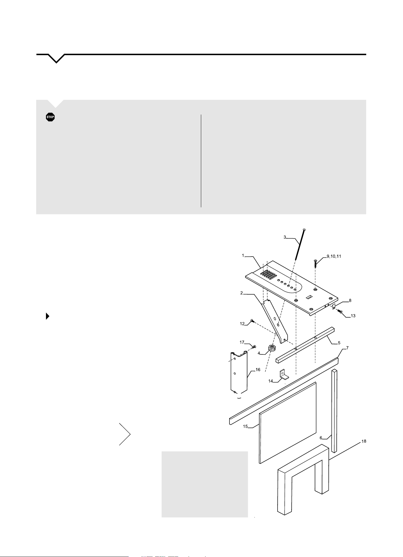
STEP 1:
MAKE SURE YOU HAVE ALL THE
NECESSARY PARTS
Installationkitcontents:
1. Platform(1)
2. Supportbrace(1)
3. Adjustmentbolt(1)
4. Hexangenut-1/4”(1)
5. Trackseal(1)
6. Sidechannelseal(1)
7. Foamsealstrip/sashseal(1)
8. Safetybracket(1)
9. Screw-21/2”(2)or
10. Screw-13/4”(2)or
11. Screw-1”(2)
12. Screw-3/4”(6)
13. Screw-3/4”self-threading(7)
14. Windowlockingbracket(1)
15. Plasticwindowpanel(1)
16. Sidechannel(2)
17. Screw-3/8”(6)
18. Panelframe/sealassembly(1)
You will have only
one of these sets
of screws:
#9, #10 or #11.
Tools Required (Not Included):
•Flat-headscrewdriver
•Phillips-headscrewdriver
•Carpenter’slevel
•Tapemeasure
•Finetoothsaw
•Electricorhanddrill
PREPARING FOR INSTALLATION
5
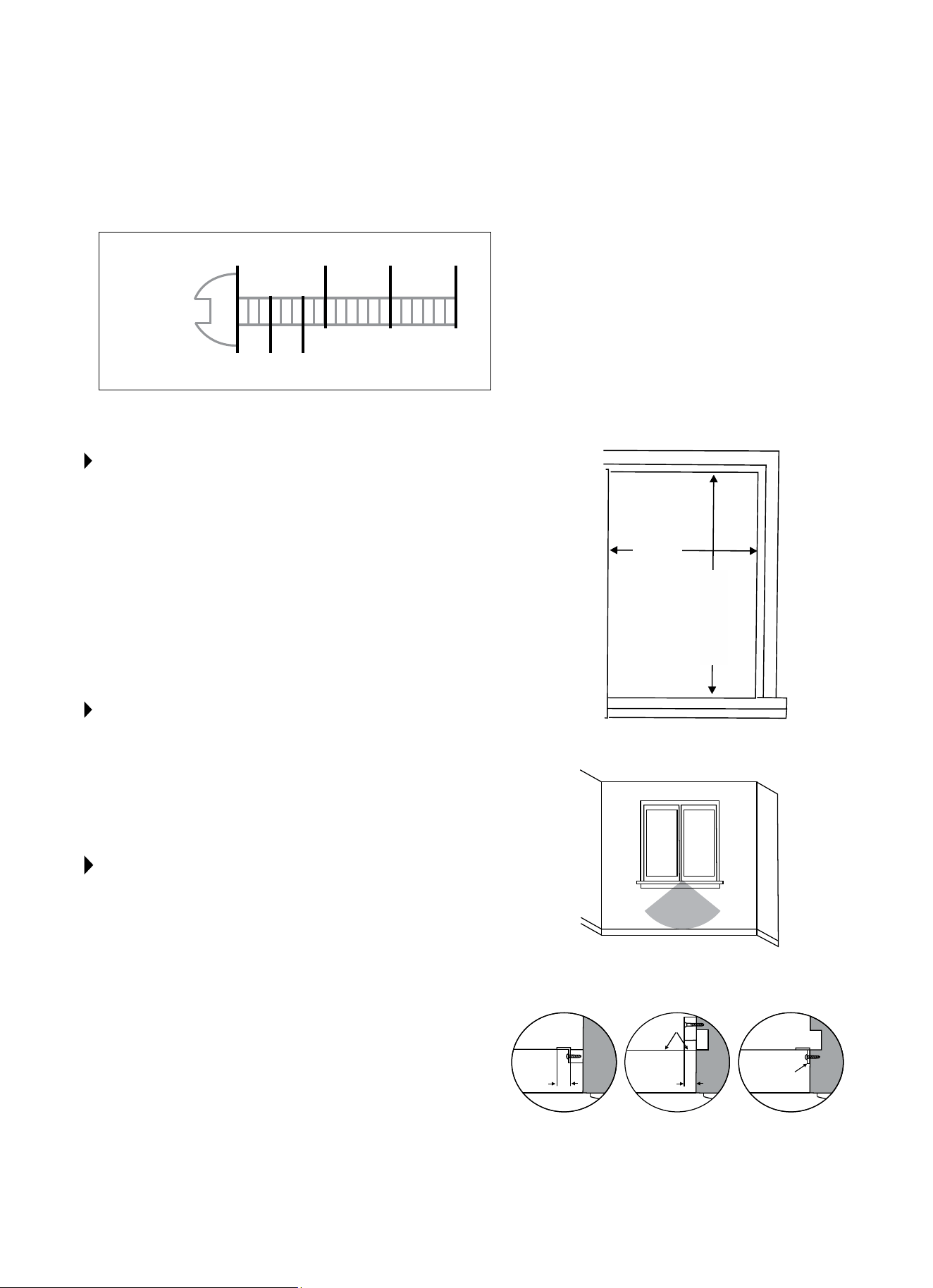
NOTE: Use scale below to measure length of your screws The
scale will be helpful when separating screws for installation.
STEP 2:
CHOOSE PROPER SIZED WINDOW, AS
SHOWN TO THE RIGHT.
•15½inchesmin.width
•16¼inchesmax.width(forcasementwindows)
•21¼inchesmin.height(withwindowpanelretainer)
•20
5
/16inchesmin.height(windowpanelretainerremoved)
•39
7
/16 inches max. height
NOTE: Height measurement must be of a clear opening above
mounting platform. In some cases, due to a variety of stop and
trackarrangements,theabovedimensionsmayvaryslightly.
If necessary, installation can be made by alternating window
jambs.(SeeAlternateWindowJambApplicationsbelow).
STEP 3:
CHOOSE THE PROPER WINDOW LOCATION
Chooseawindowthatallowsthecooledairtoowfreelyand
directlyintoroom(s)youwishtocool.Remember,itisdicult
to move air around corners. Also, choose a window that is
within6feetofanelectricaloutlet.(See“ElectricalInformation”
onPage3).DO NOT USE AN EXTENSION CORD.
ALTERNATE WINDOW JAMB APPLICATIONS
Toinstallinwindowshavingnoangesorwoodstopson
thetopandsidejambs,thechannelsandpanelframemust
tagainstamountingange(or1/16-inchmax.thickangle)
attachedtothewindowjambs.FigureAshowsthisangle
installed.FiguresB&Cshowalternatetreatments.Onthe
sash side of the opening, the leading corner of the inner sash
becomestheange.Youcanpurchasetheanglestriplocally.
Identify Screws
By Length
(25mm)
1” 1 3/4”
(63mm)
2 1/2”
3/8” 3/4”
(19mm)
(44mm)
(10mm)
15½ in.
minimum
width
A
Add angle to
wood stop
Room
3/4"
or 1"
3/4"
or 1"
3/4" x 3/4"
or 1" x 1"
Room Room
B
Add wood
as shown
C
Add 16- or 18-
gauge angle
20
5
/16 in.
minimum
height
39
7
/16 in.
maximum
height
6 foot
power cord
reach
16¼ in.
max. width
(casement
windows)
6
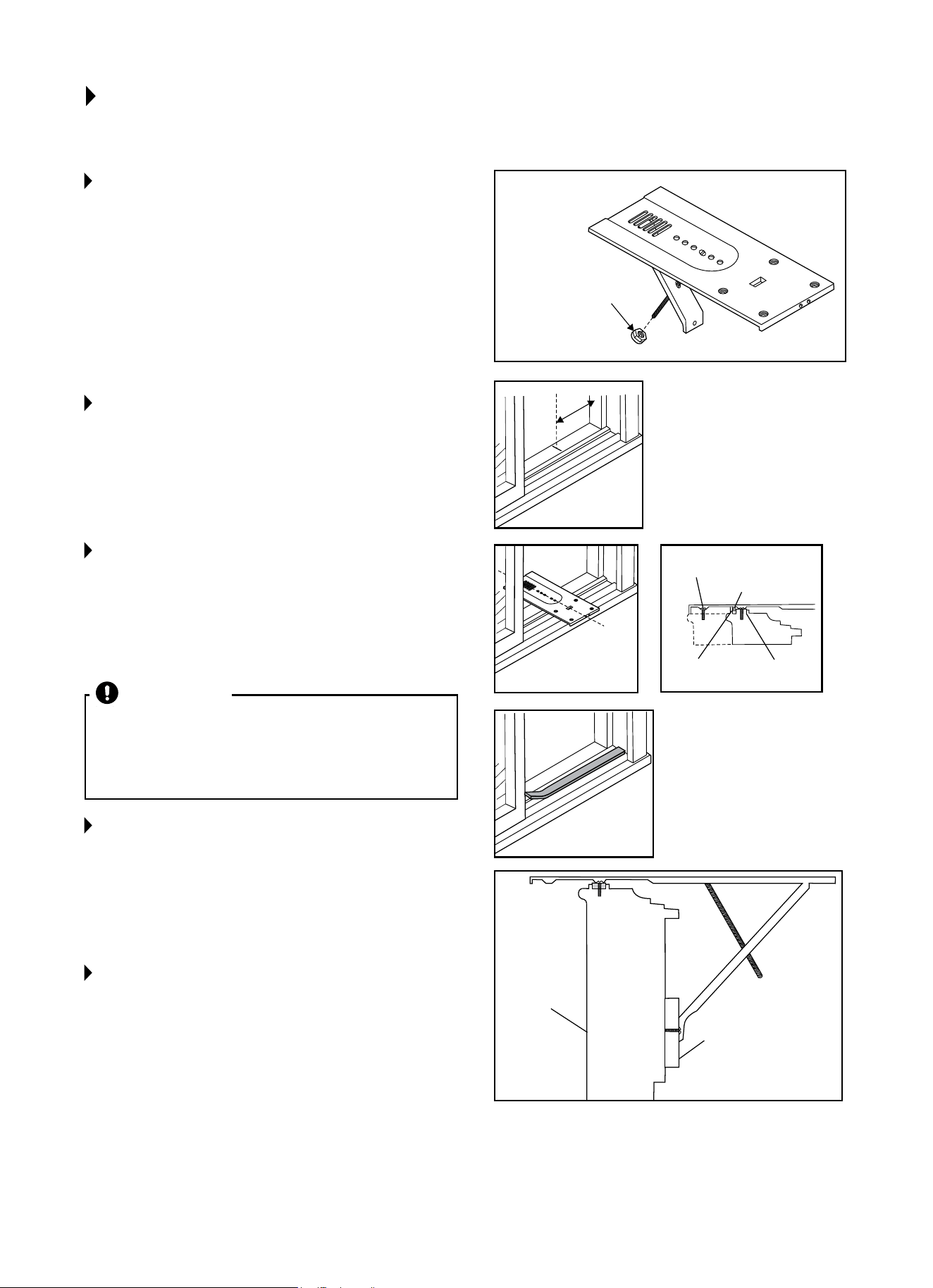
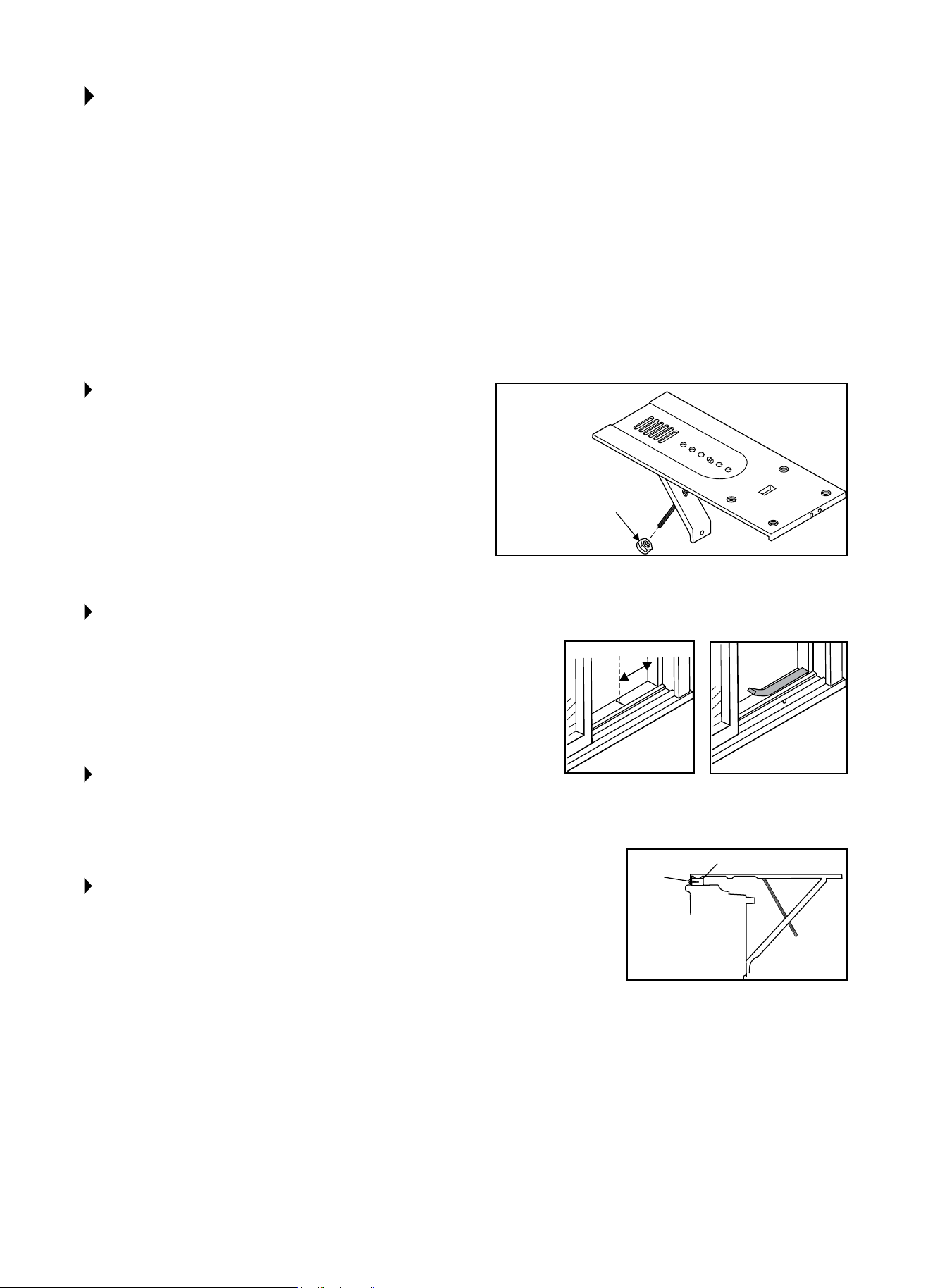
STEP 1:
ATTACH SUPPORT BRACE TO PLATFORM
Useadjustmentboltandhexangenuttocomplete
assembly.Chooseslotandadjustmentboltholelocations
thatwillcreatea45degreeanglebetweenplatformand
support brace. Try assembly in the window to determine
ifplatformwillrestproperly,andallowproperslope.(
5
/16"
loweronoutside).(Fig.1)
NOTE: If you are planning to use a sliding-protection board
(SeeStep5)ontheoutsideofyourhouse,holdboardin
place when testing assembly of window.
STEP 2:
MEASURE, AND LIGHTLY MARK A LINE
8
11
/16" FROM WINDOW JAMB.
NOTE: If any sash stop protrudes more than 1" from the
sidewindowjambs,the8
11
/16" measurement must be
increased accordingly. Screen and storm window frames
mayalsorequireadjustmentstothemeasurement.(Fig.2)
STEP 3:
CENTER PLATFORM ASSEMBLY.
Center the platform assembly on the line with inside
platformtabpressedagainstinsideedgeofwindowtrack.
Usingtheholesintheplatformasaguide,markanddrill
two
9
/64"diameterholes.Drillholesineithertrackorstool.
(Fig.3&Fig.4)
STEP 4:
PEEL OFF PROTECTIVE BACKING FROM
TRACK SEAL.
Next,applysealtoroomsideofwindowtrack.Centerof
sealstripshouldcoincidewiththelinemarkedinStep2.
The two screw holes drilled in Step 3 should be directly
abovesealstripintheinnertrack.(Fig.5)
STEP 5:
SECURELY ATTACH A SIDING-PROTEC-
TION BOARD TO SIDE OF HOUSE.
NOTE: Siding-protection board should be long enough to
span 2 wall studs.
NOTE:Adjusttheplatformassemblysothattheair
conditionerwillbe1⅛"to1½"lowerthanthefront(tilted
about3ºto4ºdownwardtotheoutside).Afterproper
installation, condensation should not drain from the
overowdrainholeduringnormaluse.(Youmaysee
condensation in periods of high humidity. However, if
condensationoccursduringlowornormalhumidity,adjust
theslopeslightly.)(Fig.6)
Fig. 1
Fig. 2
Fig. 3
Fig. 6
Fig. 5
Fig. 4
INSTALLING UNIT IN A SLIDING WINDOW
CAUTION
Property Damage Hazard-Failure to adhere to the
following precaution could result in damage to window
or air conditioner. Besurewoodstoolorwindowtrack
is securely attached to the building construction. Use
longer screws in sub-framing if necessary.
¼ in. (6mm)
HEX FLANGE NUT
8
11
/16 inches
Center platform
assembly on the
line with platform
tab pressed against
window track.
Alternate screw location
(depending on the stool depth)
Apply track seal
to window side
of track.
Platform tab
Window seal
Window track
Platform Assembly
Inside wall
of house
Siding-protection
board
7
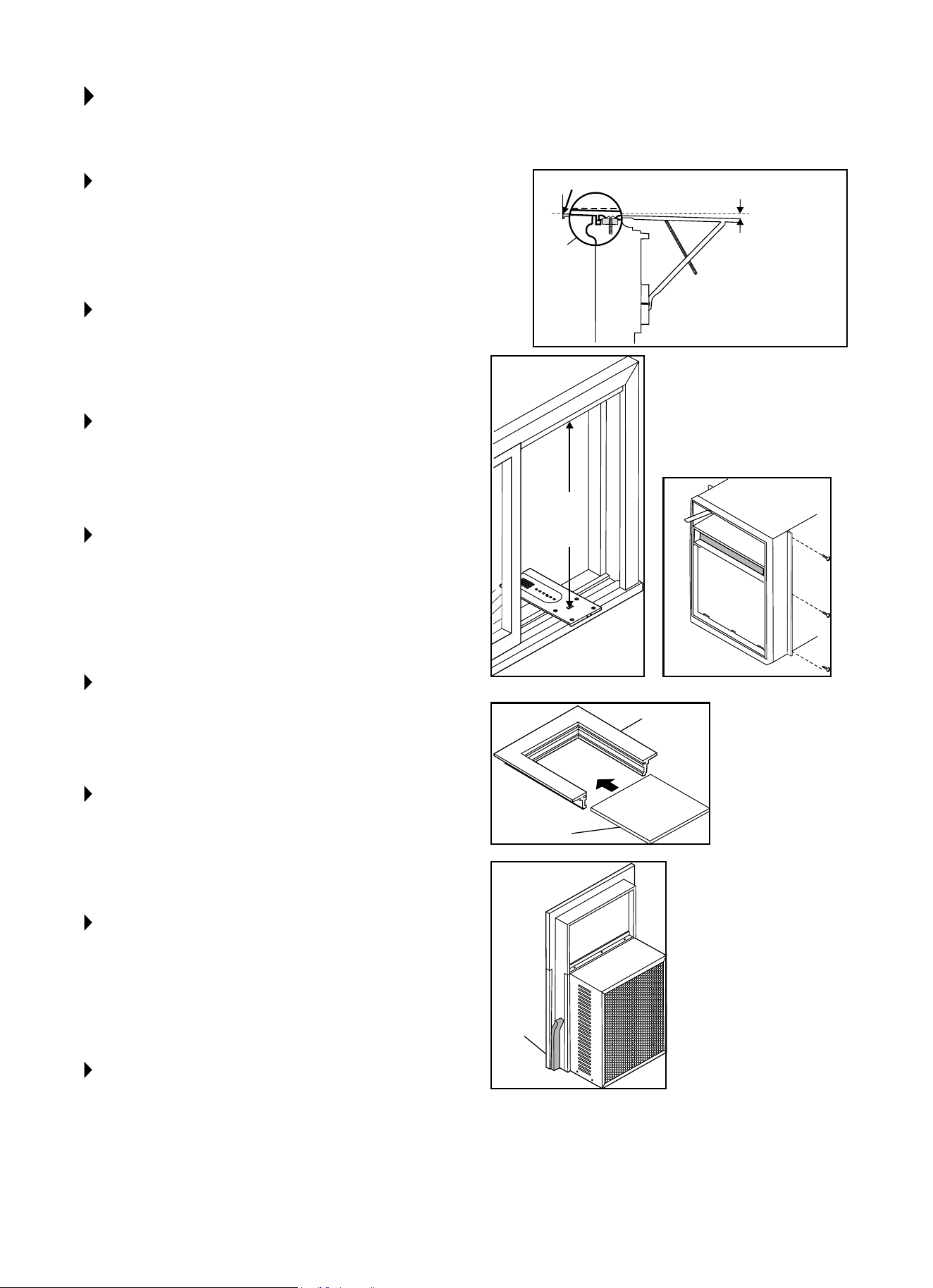
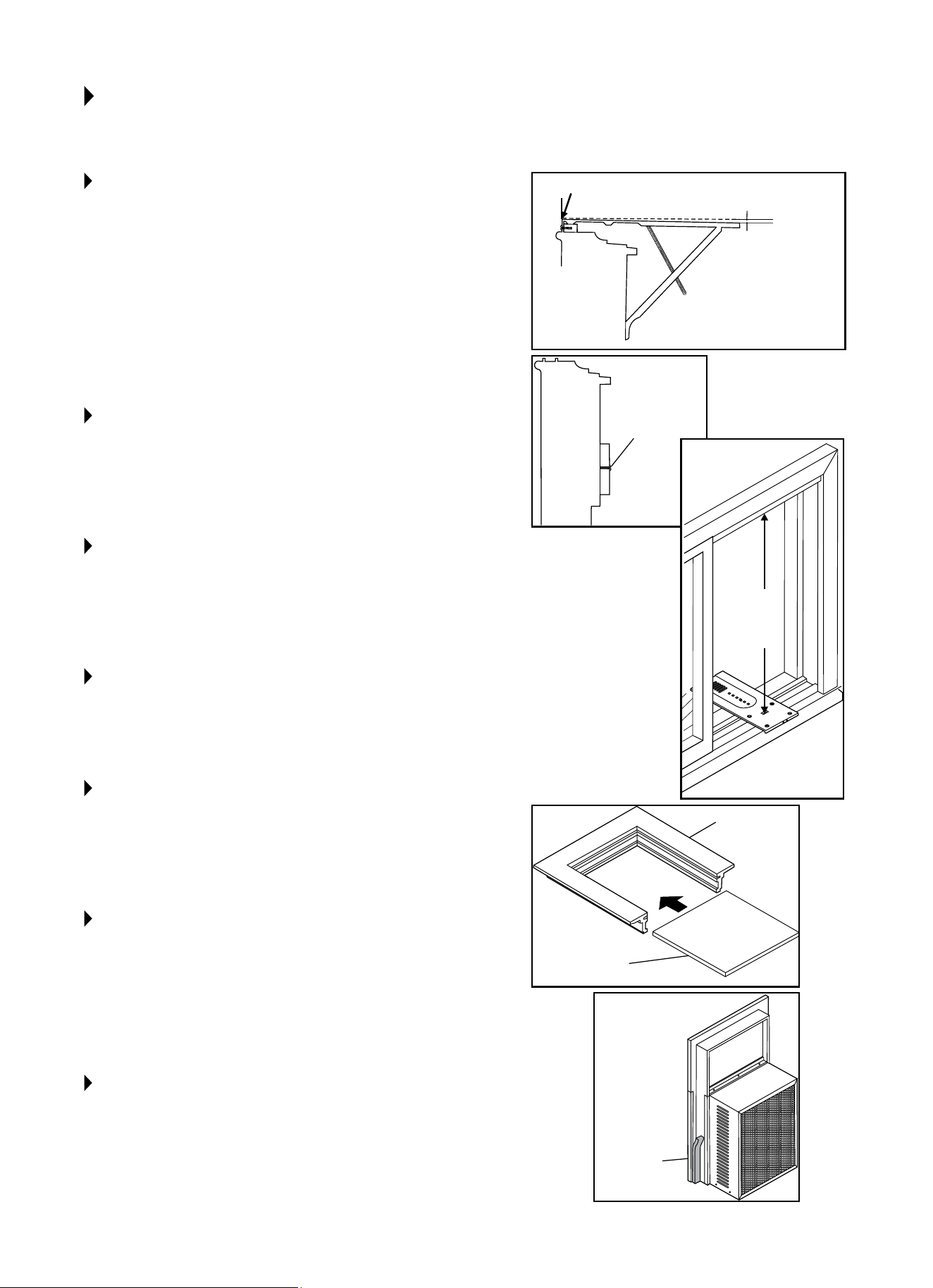
STEP 6:
PLACE PLATFORM ASSEMBLY
Withplatformtabagainstinsideofwindowtrack,place
platformassemblyandattachittowindowjamb.Use
appropriatelengthscrews(Items9–11inPreparingFor
Installationonpg.4).(Fig.7)
STEP 7:
ADJUST PLATFORM ASSEMBLY
Adjusttheplatformassemblysothattheoutsideedgeis
5
/16incheslowerthaninsideedge.(Fig.7)Thisensures
proper water drainage from the air conditioner.
STEP 8:
LEVEL PLATFORM ASSEMBLY FROM
SIDE-TO-SIDE
Also,makesurewindowtrackislevel.Uselevelingshims
as necessary to ensure unit is level from side-to-side.
STEP 9:
MEASURE HEIGHT OF WINDOW
OPENING
Begin measuring height of window opening from top of
platform assembly as shown right. Subtract 20
5
/8 inches.
Markthismeasurementonplasticwindowpanel,alongthe
longerside.(Fig.8)
STEP 10:
CLAMP PLASTIC WINDOW PANEL
Clamp the plastic window panel between a board and a
worktable,andcutalongcuttinglinewithanetoothsaw.
Removeanyburrswithale.
STEP 11:
FASTEN SIDE CHANNELS
Fasten the side channels to the sides of the unit using
3screws(Item#17,page4)perchannel.Startwithrst
screwattopofchannel.Makesurehookendsofchannels
facetowardbackofunit.(Fig.9)
STEP 12:
SLIDE PLASTIC WINDOW PANEL INTO
PANEL FRAME
Slide in the window panel, with the smooth side facing the
room. Slide panel frame assembly into side channels of
theACcabinet.Makesureplasticwindowpanelisrmly
enclosedonallsidesbytheretainergrooves.(Fig.10)
STEP 13:
CUT SIDE CHANNEL SEAL
Cutthesidechannelsealinto2equallengths.Remove
protectivebackingandapplyittotherearsideofcabinet
sidechannels,startingjustbelowpanelframeassembly.
Pinchoexcesslengthsosealisevenwiththebottomof
thecabinetsidechannel.(Fig.11)
Fig. 7
Fig. 8
Fig. 9
Fig. 10
Fig. 11
Measure from here
Put
platform
tab against
inside of
track.
Fastening Side
Channels
Panel
Frame
Plastic
window panel
Measure
distance
& subtract
20⅝in.
approx. 1" to 1¼"
Apply
weather
seal to side
channels
just below
edge of
panel frame
INSTALLING UNIT IN A SLIDING WINDOW (CONT.)
8
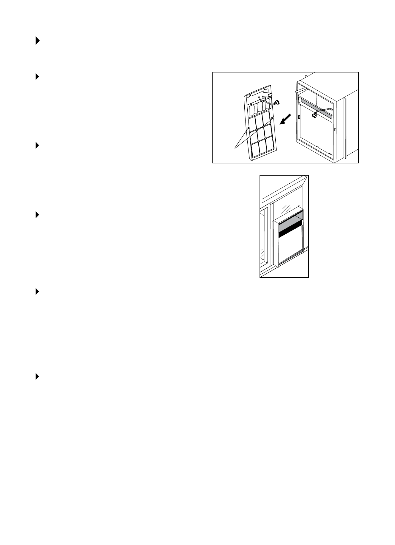
Fig. 12
Fig. 13
Fig. 14
Fig. 15
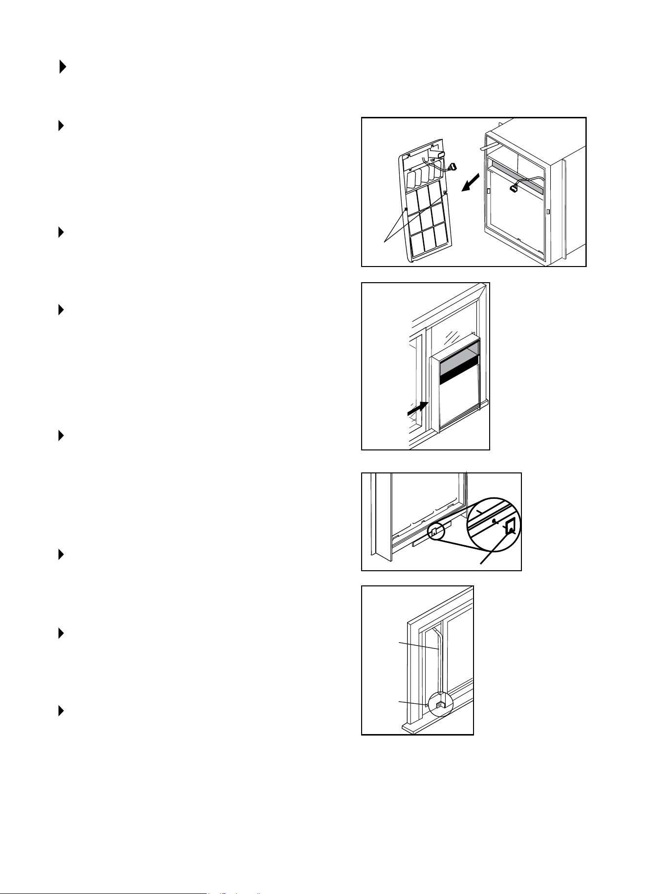
STEP 14:
TO REMOVE FRONT
1. Remove the two front retaining screws from the
frontframe.(Fig12)
2. Gently pull the front out and lift up to release it from
the case.
3.Releasethecontrolboardplug.(Fig.12)
NOTE: DO NOT push or pull air direction louvers.
STEP 15:
PLACE AC IN WINDOW OPENING
The unit should sit on the platform assembly so that the
window panel frame and cabinet side channels are against
thetopandsidewindowjambs.(Fig.13)
STEP 16:
SLIDE INNER WINDOW SASH FIRMLY
AGAINST SIDE OF CABINET
Makesurenottopeelthesealstripsfromthewindowtrack
andcabinetsidechannels.Ifthepanelframedoesnott
snugly to the inner window sash, secure the panel frame to
the sash with ¾" screws, or ¾" self-threading screws. Use
thepartiallypluggedholesinthepanelframe.Drill⅛"pilot
holesforthescrews.(Fig.13)
STEP 17:
HOOK THE SAFETY BRACKET
Thesafetybracketshouldbehookedoverthebaseofthe
unit and fastened to the front of the platform assembly. Use
a¾"self-threadingscrew.(Fig.14)
NOTE: Thebracketpreventsmovementoftheair
conditioner(eitherinorout)aftercompletingthe
installation.
STEP 18:
STUFF THE FOAM SEAL STRIP/
SASH SEAL
Stuthefoamsealstripbetweentheverticalsashandthe
windowglass.(Fig.15)
STEP 19:
LOCK THE INNER WINDOW SASH
Usingthewindowlockingbracket,locktheinnerwindow
sash to the base of the outer window sash. Use one ¾"
screw,or¾"self-threadingscrew.(Drill⅛"pilothole).
STEP 20:
TO REPLACE THE FRONT
First,reconnectthecontrolboardplug.Makesurethe
exhaust control positioned through the front is in the proper
location. Then, replace the retaining screws that hold the
panel in place. Do not push or pull the front louvers.
Safety Bracket
Sash
Seal
Window
locking
bracket
Front
Retaining
Screw
Slide inner
window
sash firmly
against
cabinet
INSTALLING UNIT IN A SLIDING WINDOW (CONT.)
9
NOTE: Openthewindowthemaximumamounttoallow
forclearanceofthecabinet.Thecrankhandleshouldbe
removedtoallowtheplatformtobefastenedtothejamb.
Ifthewindowcannotopenfarenough(morethan15½
inches)forthecabinettoclearthewindow,removethe
window entirely by drilling out the rivets. Bolts can serve as
the rivets in the future.
Toavoidcrankhandleandwindowclearanceproblems,the
unit can be installed in a stationary sash section. However,
thehorizontalmullionandthe2glasspanelsmustbe
removed before installation.
STEP 1:
ATTACH SUPPORT BRACE TO PLATFORM
Usetheadjustmentboltandhexangenuttocomplete
theassembly.Choosetheslotandadjustmentbolthole
locationsthatwillcreatea45degreeanglebetweenthe
platform and the support brace. Try the assembly in the
window to determine if the platform will rest properly, and
allowtheproperslope(
5
/16inchloweronoutside).(Fig.1)
NOTE: If you are planning to use a siding-protection board
(SeeStep6)ontheoutsideofyourhouse,holdtheboard
in place when testing the assembly in the window.
STEP 2:
DRILL A 9/64 IN. DIAMETER PILOT HOLE
Drilltheholeinthewindowjambanequaldistancefrom
eachsideofthejamb(Fig.2),and3/16inchupfromthe
window sill. If the hole coincides with the window lever
slotinthejambbottom,anadditionalholewillhavetobe
drilledthroughtheplatformedgeandthewindowjambto
miss this slot.
STEP 3:
PEEL OFF THE PROTECTIVE BACKING
Peelothebackingfromthetrackseal,andsticktheseal
tothewindowsillontheoutsideofthebottomjamb.
(Fig.3)
STEP 4:
SCREW THE PLATFORM ASSEMBLY TO
THE WINDOW JAMB
Screw the platform assembly using the pilot hole drilled in
Step2.Usea¾inchself-threadingscrew.(Fig.4)
INSTALLING UNIT IN A CASEMENT WINDOW
Fig. 1
Fig. 2 Fig. 3
Fig. 4
¼ in. (6mm)
HEX FLANGE NUT
8
11
/16 inches
Platform Assembly
Track seal
Screw
Window
Jamb
10
STEP 5:
ADJUST PLATFORM ASSEMBLY PROPERLY
Adjusttheplatformassemblysothattherearoftheair
conditioner is
5
/16 inches lower than the front. This ensures
properwaterdrainagefromtheairconditioner.(Fig.5)
NOTE:Adjusttheplatformassemblysothattheairconditioner
willbe1⅛"to1½"lowerthanthefront(tiltedabout3ºto4º
downwardtotheoutside).Afterproperinstallation,condensation
shouldnotdrainfromtheoverowdrainholeduringnormal
use.(Youmayseecondensationinperiodsofhighhumidity.
However, if condensation occurs during low or normal humidity,
adjusttheslopeslightly.)
STEP 6:
SECURELY ATTACH A SIDING-
PROTECTION BOARD
Attach the board to the side of the house where the platform
assembly hits the house. The siding-protection board should be
longenoughtospan2wallstuds.(Fig.6)
STEP 7:
MEASURE THE HEIGHT OF THE
WINDOW OPENING
Measurefromthetopoftheplatformassembly.Subtract20⅝
inches.Markthismeasurementontheplasticwindowpanel,
alongthelongerside.(Fig.7)
STEP 8:
CLAMP THE PLASTIC WINDOW PANEL
Clamptheplasticwindowpanelbetweenaboardandawork
table,andcutalongthecuttinglinewithanetoothsaw.
Removeanyburrswithale.
STEP 9:
FASTEN THE SIDE CHANNELS TO THE SIDE
OF THE UNIT
Usingthreescrews(Item#17,Pg.4)perchannelfastenthe
sidechannelstothesideoftheunit.Makesurehookendsof
channelsfacetowardthebackofunit.
STEP 10:
SLIDE THE PLASTIC WINDOW PANEL INTO
PANEL FRAME
Slide the plastic window panel in, with the smooth side facing
the outside. Slide the panel frame assembly into the side
channelsoftheairconditionercabinet.Makesuretheplastic
window
panelisrmlyenclosedonallsidesbytheretainer
grooves.(Fig.8)
STEP 11:
CUT SIDE CHANNEL SEAL
Cutthechannelsealinto2equallengths.Removetheprotective
backingandapplyittotherearsideofthecabinetside
channels,startingjustbelowthepanelframeassembly.Pincho
excess length so the seal is even with the bottom of the cabinet
sidechannel.(Fig.9)
INSTALLING UNIT IN A CASEMENT WINDOW (CONT.)
Fig. 6
Fig. 5
Fig. 7
Fig. 8
Fig. 9
Measure from here
approx. 1⅛" to 1½"
Measure
distance
& subtract
20⅝in.
Fasten
sliding-
protection
board to
the house
siding.
Apply
weather
seal to side
channels
just below
edge of
panel frame.
Panel frame
Plastic window
panel
11
STEP 12:
TO REMOVE FRONT:
• Removethetwofrontretainingscrewsfromthe
frontframe.(Fig.10)
• Gentlypullthefrontoutandliftuptoreleaseitfrom
the case.
• Releasethecontrolboardplug.(Fig.10)
NOTE: DO NOT push or pull air directional louvers.
STEP 13:
PLACE THE AIR CONDITIONER IN THE
WINDOW OPENING
The air conditioner should sit on the platform assembly
so that the window panel frame, and the cabinet side
channelsareagainstthetopandsidewindowjambs.Side
channelsshouldoverlapsidewindowjambsequally.
(Fig.11)
STEP 14:
DRILL TWO 9/64 INCH DIAMETER
PILOT HOLES
Drillthetwopilotholesinthetopwindowjambinline
with the partially plugged holes in the panel frame.
Securethepanelframetothewindowjambwithtwo
¾ inch self-threading screws. If additional holding is
necessary, two screws may be used on the sides of the
panel frame as well.
STEP 15:
DRILL SCREW-CLEARANCE HOLES
Drill two screw-clearance holes in the cabinet side
channels(nearbottom)andtwo
9
/64 inch diameter pilot
holesinthesidewindowjambs.Securethecabinetside
channelstothewindowjambswithtwo¾inchself-
threading screws. When doing this, be careful not to twist
the side channel seals with the screws.
NOTE: Inserting screws will prevent the air conditioner from
being pushed into the room.
STEP 16:
TO REPLACE THE FRONT
First,reconnectthecontrolboardplugandmakesurethe
exhaust control positioned through the front is in the proper
location. Then replace the retaining screws that hold the
panel in place. Do not push or pull the front panel louvers.
INSTALLING UNIT IN A CASEMENT WINDOW (CONT.)
Fig. 10
Fig. 11
Front
Retaining
Screw
12
NORMAL SOUNDS
AIR CONDITIONER FEATURES
VIBRATION
Unitmayvibrateandmake
noise because of poor wall
or window construction
or incorrect installation.
ThisDOESNOTindicatea
defective unit.
PINGING OR SWITCHING
Droplets of water hitting
condenser during normal
operation may cause “pinging”
or “switching” sounds.
HIGH PITCHED CHATTER
Higheciencycompressors
may have a high pitched chatter
during the cooling cycle.
SOUND OF RUSHING AIR
At the front of the unit,
the sound of rushing air
being moved by the fan
may be heard.
GURGLE/HISS
“Gurgling” or “hissing”
noise may be heard due
to refrigerant passing
through evaporator during
normal operation.
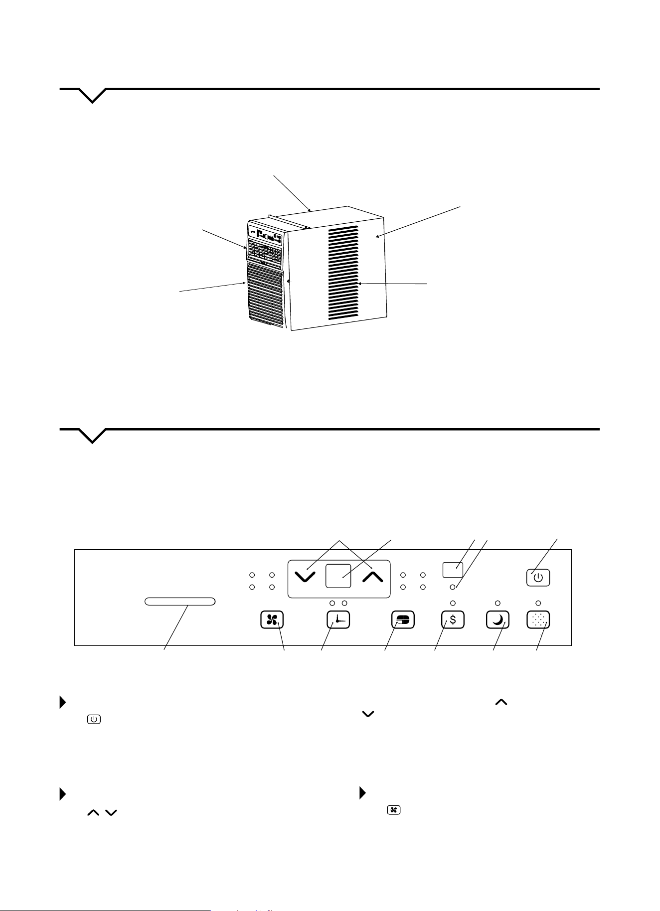
NOTE: Allofthepicturesinthismanualareforexplanatorypurposesonly.Theactualshape/lookof
theairconditionerpurchasedmaybeslightlydierent,buttheoperationsandfunctionsaresimilar.
Thoroughlyfamiliarizeyourselfwiththecontrolpanelshownbelowandallofitsfunctions.Afterwards,followthesymbol
forthefunctionsyoudesireBEFOREoperatingtheunit.Thisunitcanbecontrolledbytheunitcontrolorwiththe
remote control.
“FOLLOW
ME”
Indicator
Energy Saver
Mode
Sets
Mode
Sleep
Mode
Turns Unit
On or Off
Sets Fan
Speed
Adjusts Temp.
or Time
Exhaust Selector
Remote
Signal
Receptor
Check Filter
Reset Button
Activates
Timer
Displays Temp. or
the Time or
Error Codes
TO TURN UNIT ON OR OFF:
Press ON/OFFbuttontoturntheunitonoro.
NOTE: The unit will automatically initiate the Energy
SaverfunctionunderCOOL,DRYandAUTO(only
AUTO-COOLINGandAUTO-FANmodes).
TO CHANGE TEMPERATURE SETTING:
Press / UP/DOWNbuttontochangethe
temperature setting.
NOTE: PressorholdeitherUP(
)orDOWN
( )buttonuntilthedesiredtemperatureisseenon
the display. The temperature will be automatically
maintainedanywherebetween62°F(17°C)and86°F
(30°C).Ifyouwantthedisplaytoreadtheactualroom
temperature,see“ToOperateonFanOnly”section.
TO ADJUST FAN SPEEDS:
Press to select the Fan Speed in four steps: Auto,
Low, Med or High. Each time the button is pressed,
thefanspeedisshifted.InDRYmode,thefanspeed
is controlled at Low automatically.
Close
Open
Auto
Low
Med High
Auto
On
Off
Cool
Dry Fan
Follow Me
Exhaust
Fan
Timer Mode
Energy
Saver
Sleep
Check
Filter
TEMP/TIMER
13
SLEEP FEATURE:
Press the SLEEP button to initiate SLEEP
mode. In this mode, the selected temperature will
increaseby2°F(1°C)30minutesafterthemodeis
selected.Thetemperaturewillthenincrease(cooling)
ordecrease(unitswithheatingonly)byanother
2°F(1°C)afteranadditional30minutes.Thisnew
temperature will be maintained for 6 hours before it
returns to the originally selected temperature. This
ends the SLEEP mode and the unit will continue
to operate as originally programmed. The SLEEP
mode program can be canceled at any time during
operation by pressing the SLEEP button again.
CHECK FILTER FEATURE:
Press the CHECK FILTER button to initiate this
feature. This feature is a reminder to clean the Air
Filterformoreecientoperation.TheLED(light)will
illuminateafter250hoursofoperation.Toresetafter
cleaningthelter,presstheCHECK FILTER button
andthelightwillgoo.
ENERGY SAVER FEATURE:
Press the ENERGYSAVER button to initiate this
function. This function is available on COOL, DRY
and AUTO(onlyAUTO-COOLINGand AUTO-FAN)
modes. In this mode, the fan will continue to run for 3
minutesafterthecompressorshutso.Thefanthen
cycles on for 2 minutes, at 10 minute intervals, until
the room temperature is above the set temperature,
atwhichtimethecompressorturnsbackonand
cooling starts.
FOLLOW ME FEATURE:
This feature can ONLY be activated
from the remote control. The
remote control serves as a remote
thermostat allowing for precise
temperature control at its location.
To activate the Follow Me feature, point the remote
control toward the unit and press the FOLLOWME
button. The remote displays the actual temperature
at its location. The remote control will send this
signal to the air conditioner every 3 minutes until the
FOLLOWME button is pressed again. If the unit does
not receive the Follow Me signal during any 7 minute
interval, the unit will beep to indicate use of the
Follow Me feature has ended. The actual temperature
can be displayed at the unit by pressing the FAN only
mode.WhenintheCOOLmode,theunitdisplay
indicates the set temperature.
TO SELECT THE OPERATING MODE:
To choose operating mode, press the MODE
button. Each time you press the button, a mode is
selectedinasequencethatgoesfromAUTO,COOL,
DRY and FAN. The indicator light will be illuminated
and remain on once the mode is selected. The unit
will automatically initiate the Energy Saver function
under COOL, DRY, and AUTO (only AUTO-COOLING and
AUTO-FAN) modes.
TO OPERATE AUTO FEATURE:
When you set the air conditioner in AUTO mode, it
will automatically select cooling or fan only operation
depending on what temperature you have selected
and the room temperature. The air conditioner will
automatically control room temperature around the
temperature you set. In this mode, the fan speed
cannot be adjusted. It starts automatically at a speed
according to the room temperature. If the room does
not get too warm, it will stay at a “Low” speed.
TO OPERATE FAN ONLY:
Usethisfunction(
)onlywhencoolingisnot
desired, such as for room air circulation or to exhaust
staleair.(Remembertoopentheventduringthis
function,butkeepitclosedduringcoolingfor
maximumcoolingeciency.)Youcanchooseany
fan speed you prefer. During this function, the display
will show the actual room temperature, not the set
temperature as in the cooling mode. Temperature
cannotbeadjustedintheFANonlymode.
TO OPERATE DRY MODE:
In this mode, the air conditioner will reduce air
humidity. If the space is a closed or sealed area,
some degree of cooling will continue.
TIMER: AUTO START/STOP FEATURE:
● Whentheunitisonoro,rstpressthe
TIMERbutton.TheTIMERONindicatorlight
illuminates and indicates the Auto Start program
is initiated.
● WhenthetimeofTIMERONisdisplayed,pressing
the TIMER button again illuminates the TIMER
OFFindicatorlightandindicatestheAutoStop
program is initiated.
● PressorholdtheUPorDOWNbuttontochange
theAutotimeby0.5hourincrements,upto10
hours, then by 1 hour increments, up to 24 hours.
The control will count down the time remaining
until start.
● Theselectedtimewillregisterin5secondsand
thesystemwillautomaticallyrevertbackto
displaying the previous temperature setting or the
roomtemperature(dependingonwhethertheunit
ispoweredonoroandthemodeitisin).
● TurningtheunitONorOFFatanytimeor
adjustingthetimersettingto0.0willcancelthe
AutoStart/Stopprogram.
A NOTE ABOUT THE TIMER:
When you set the timer, the
unitwillonlygoononceandoonce.Ifyouwantthe
airconditionertocycleonandobasedondesired
room temperature, you do not need to set the timer.
Instead, set your desired temperature and the unit will
cycleonandobasedonthattemperaturesetting.
Light
Flashing
Follow Me
14
DISPLAY:
Shows the set temperature in °F or °C and the Auto-
timer settings. While on FAN only mode, it shows the
room temperature.
TEMP/TIMER
ERROR CODES:
AS - Room Temperature Sensor Error - Unplug the
unitandplugitbackin.Iferrorrepeats,call
Consumer Services at 844-472-2473.
HS - Electric Heating Sensor Error - Unplug the
unitandplugitbackin.Iferrorrepeats,call
Consumer Services at 844-472-2473.
●- Evaporator Temperature Sensor Error - Unplug
theunitandplugitbackin.Iferrorrepeats,call
Consumer Services at 844-472-2473.
NOTE: If an error code occurs in Fan only mode, the
unitwilldisplay“LO”(looseconnection)or“HI”
(shortcircuit).
NOTE
:
Iftheunitbreaksounexpectedlyduetopowerbeing
cut, it will restart with the previous function setting
automatically when the power resumes.
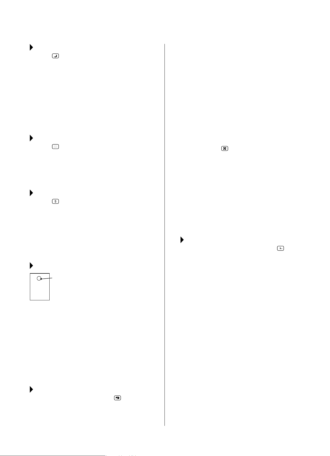
AIR DIRECTIONAL LOUVERS:
Use the 4-way directional louvers to direct the air
owupordownandleftorrightthroughouttheroom
as needed.
Move the center handles from side to side until the
desiredLeft/Rightdirectionisobtained.
ADDITIONAL THINGS YOU
SHOULD KNOW:
● TheCoolcircuithasanautomatic3minutetime-
delayedstartiftheunitisturnedoandonquickly.
Afterunitisturnedo,leaveunitoforaminimum
of3minutesbeforeattemptingtoturnbackon.
This prevents overheating of the compressor
andpossiblecircuitbreakertripping.Thefanwill
continue to run during this time.
● Thecontroliscapableofdisplayingtemperaturein
degrees Fahrenheit or degrees Celsius. To convert
from one to the other, press and hold the Up and
DownTemp/Timerbuttonsatthesametimefor
3 seconds.
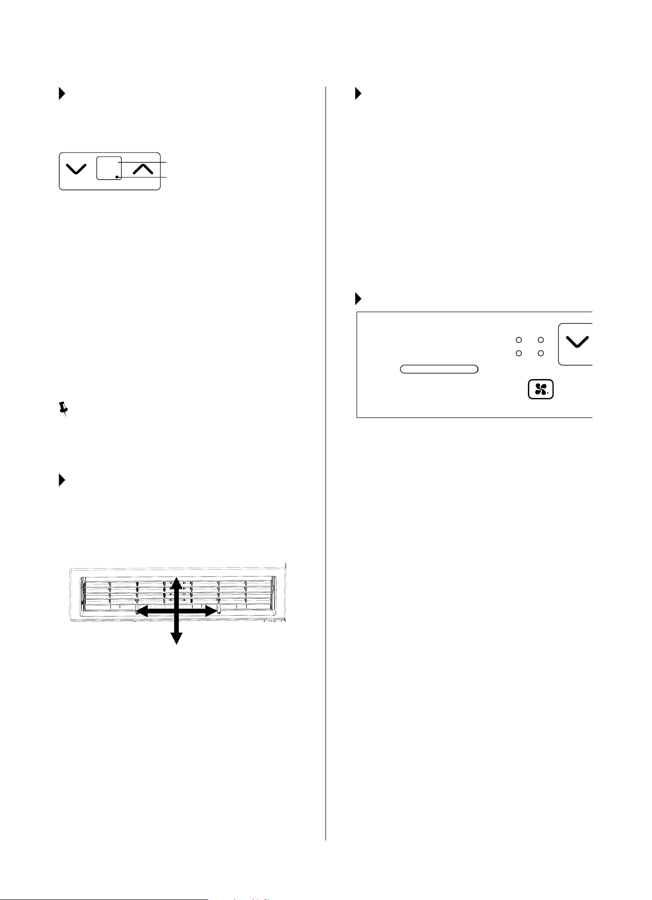
EXHAUST CONTROL
Close
Open
Auto
Low
Med High
On
Exhaust
Fan
This Exhaust Control allows the air conditioner to
eithercirculateinsideair(Closed)orexhaustairtothe
outside(Open).
The Closed position is used when maximum cooling
is desired. It may also be used for air recirculation
without cooling when the air conditioner is set in any
FAN position.
TheOpenpositionremovesstaleairfromtheroom
and exhausts it to the outside. Fresh air is drawn in
through normal passages in the home.
Display
Evaporator Temperature Sensor Error
Air Direction (4-way)
15
CARE AND CLEANING
CAUTION
Cleanairconditioneroccasionallytokeepitlookingandoperatinglikenew.
Be sure to unplug the unit before cleaning to prevent shock or fire hazards.
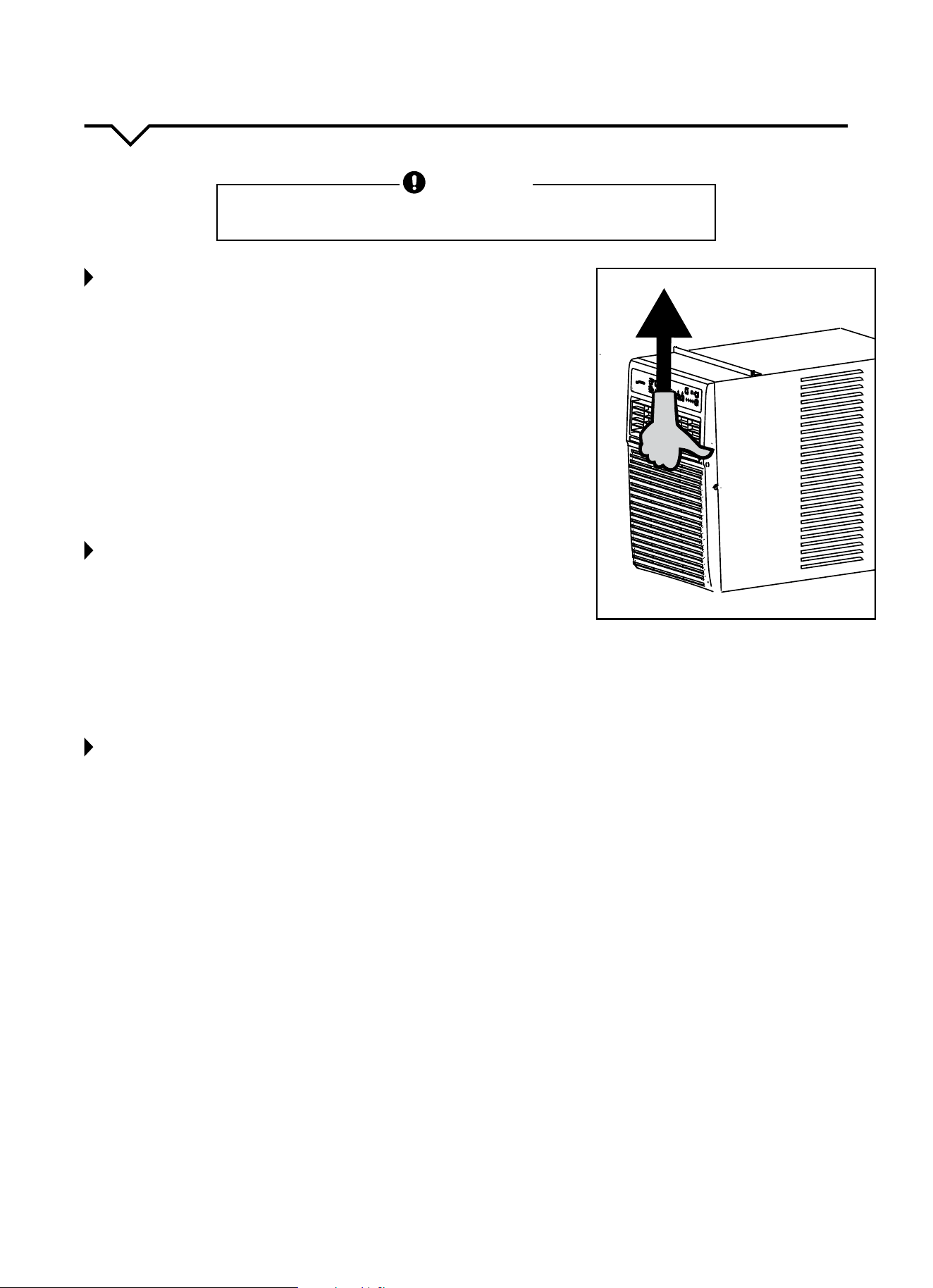
AIR FILTER CLEANING
Theairltershouldbecleanedatleasteverytwoweeksoras
necessary.Trappedparticlesintheltercanbuildupandcausean
accumulationoffrostonthecoolingcoils,reducingeciency.
● Graspthelterbythecenterandpullupandout.
● Washthelterusingliquiddish-washingdetergentandwarmwater.
Rinselterthoroughly.
● Gentlyshakeexcesswaterfromthelter.Besurethelteristhoroughly
dry before replacing.
● Asanalternativetowashingthelter,vacuumthelterclean.
NOTE: Neverusehotwaterover104°F(40°C)tocleantheairfilter.Never
attempt to operate the unit without the air filter.
CABINET CLEANING
● Besuretounplugtheairconditionertopreventshockorrehazard.
The cabinet and front may be dusted with an oil-free cloth or with
aclothdampenedinasolutionofwarmwaterandmildliquiddish-
washing detergent. Rinse thoroughly and wipe dry.
● Neveruseharshcleaners,waxorpolishonthecabinetfront.
● Besuretowringexcesswaterfromtheclothbeforewipingthe
controls. Excess water in or around the controls may cause damage to
the air conditioner.
● Pluginairconditionerafterunithasdriedcompletely.
WINTER STORAGE
If air conditioner will be stored during the winter, remove it carefully from
the window according to the installation instructions. Cover it with plastic
or return it to the original carton.
ALWAYS STORE UNIT IN AN UPRIGHT POSITION AND IN A COOL, DRY LOCATION.
The design and specifications are subject to change without prior notice for
product improvement. Consult with the sales agency or manufacturer for details.

16
NOTE
Ahighlyrecommendedtroubleshootforanyissueingeneralconsistsofturningounitandunpluggingfor5
minutes. It is also recommended to try another wall outlet. For further assistance, contact Consumer Services
at 844-472-2473.
TROUBLESHOOTING
BEFORE CALLING FOR SERVICE, PLEASE REVIEW THE CHART BELOW
ISSUE POSSIBLE CAUSES
AIR CONDITIONER NOT
COOLING ROOM, OR NOT BLOWING
COLD AIR
•Besureunitisnottoolargeortoosmallfortheareaoftheroom.
•Verifythatalldoors,windows,curtainsandanyotheropeningsareclosedo.
Verify nothing is obstructing the front grille of unit, such as curtains, etc.
•Allowenoughtimeforroomtocool,especiallyifoutsidetempisveryhigh.
•Checkthatthelterisnotdirtyandlouversareopenallthewayandblowinginthe
desired direction.
•CheckthatunitissettoCOOLmodeandthattemperatureisdownenough(but
nottoolow).
•Ifunitisnearaheatsource,suchasastove,etc.,relocateunit.
•Ifaircomingfromunitiscooltothetouch,thenunitisworkingproperly;please
doublechecktherstthreebulletpointsabove.
•IfusingFollowMeremotefeature,moveremoteawayfromunit.
•Temperaturesensorbehindairltertouchingcoldcoil.Thesetwoelementsshould
not be touching. Carefully straighten tube away from coil.
•Unplugunitforatleast5minutes.FollowResetinstructionsonplug.
AIR CONDITIONER COOLING
BUT ROOM IS TOO WARM - ICE
FORMING ON COOLING COIL
BEHIND DECORATIVE FRONT
•Outdoortemperatureisbelow64ºF(18ºC).Todefrostthecoil,settoFAN
only mode.
•Airltermaybedirty.Cleanlter.RefertoCareandCleaningsection.Todefrost,
set to FAN only mode.
•Thermostatissettoocoldfornight-timecooling.Todefrostthecoil,settoFAN
only mode. Then, set temperature to a higher setting.
AIR CONDITIONER CYCLING ON
AND OFF TOO FREQUENTLY OR
NOT ENOUGH
•Besureunitisnottoolargeortoosmallfortheareaoftheroom.
•Removegrilleandmakesurethetemperaturesensorisnottooclosetothecoils.
These two elements should not be touching. Carefully straighten tube away
from coil.
•Makesurenothingisblockingthegrilleorsidevents.
•Makesurethereisnodirtordebrisinsidetheunitoronthelter.
UNIT WILL NOT TURN ON
•Resetcircuitbreaker.Makesuretherearenottoomanyitems(i.e.lamps,TV’s,
etc.)workingothesamebreaker.
•Checkplugconnection.
•Ifplugisoperatingonanon/oswitch,besurethattheswitchis‘on’.
•Trypluggingunitintoanotheroutlet.
•Unplugunitforatleast5minutes.FollowResetinstructionsonplug.
UNIT BLOWS FUSES OR POPS
CIRCUIT BREAKER
•Makesurethereareenoughavailableampsonthecircuitfortheairconditioner.
•Largeunitswhichrunona230vwillrequireadedicated20or30ampcircuit.
AIR CONDITIONER IS
MAKING NOISES
•Checktobesuretheunitisfreefromdebrissuchasleaves,sticks,etc.Verify
nothing is obstructing the unit.
•Checkthefanbladeforcracksorchips.
•Makesuretheunitisproperlyandsecurelymountedinsidethewindoworwall.
•Cleantheairlter.
WATER PUDDLES INSIDE UNIT OR IS
COMING INTO ROOM
•Adjusttheslopeoftheunitsothatitdrainsdownwardtowardtheexteriorofthe
home.(SeeInstallationInstructions.)
•Makesurethatthereisnodebrisblockingthedrainageareaoftheunit.
WATER DRIPPING OUTSIDE
•Unitisremovingalargequantityofmoisturefromahumidroom.Thisisnormal
during excessively humid days.
REMOTE SENSING / FOLLOW ME
DEACTIVATING PREMATURELY
•Remotecontrolnotlocatedwithinrange.Placeremotecontrolwithin20ftand
180º radius of the front of the unit.
•Remotecontrolsignalobstructed.Removeobstruction.

Perfect Aire, LLC
5151 Belt Line Rd.
Suite 878
Dallas, TX 75254
Distributed by:
844-4PA-AIRE | 844-472-2473
www.perfectaire.us
WINDOW
AIR CONDITIONER
FOR MODEL:
3PASC10000
Before using your air conditioner, please
read this manual carefully and keep it for
future reference, along with your receipt.
Specification and performance data is subject to change without notice.
Printed in China
PA/User_3PASC10000/10162017
USER MANUAL