Loading ...
Loading ...
Loading ...

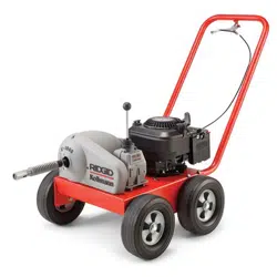
K-1000 Rodder
Ridge Tool Company6
4. Select and install proper tool/cutter to end of rod.
To connect, snap the male and female couplings to-
gether. To disconnect, insert pin key and slip apart
(Figure 2).
5. Couple enough rod together to reach down into main
and extend out no more than 20 feet.
Operating Instructions
WARNING
Rods may whip or kink. Fingers, hands or other
body parts can be crushed or broken. Carbon
monoxide poisoning can occur if operated in a
confined area.
Wear gloves provided with machine. Never grasp
a rotating rod with a rag or loose fitting cloth
glove that may become wrapped around the rod
causing serious injury.
Always wear eye protection to protect your eyes
against dirt and other foreign objects. Wear rubber
soled, non-slip shoes.
Always follow the correct operating pro-
cedure in order to maintain proper control of the machine
and rods and prevent serious injury (Figure 3).
• When working through a manhole, 2 persons are
required. Machine operator and rod handler at
manhole.
• Do not operate with more than 20 feet of rod be-
tween machine and manhole.
• Arcing of the rod at manhole should not exceed 3
feet.
• If kinking occurs, move all people to rear of machine
before shifting transmission. Violent whipping action
of rods could cause serious injury.
• If tool hangs up in obstacle, do not force the ma-
chine by manually pushing in the exposed rods.
Operating Rodder
1. Transmission shift lever should be in NEUTRAL
(straight up) position.
2. Set choke control handle to CHOKE and turn en-
gine over a few times with pull starter.
3. When engine catches, set at RUN and pull throttle
control to desired speed.
NOTE! Squeeze throttle handle to REV engine at high
speed and immediately release so that engine
returns to idle.
At idle speed, the drive shaft should not be
turning. If drive shaft does turn, make sure that throttle
control spring is connected or adjust idle speed at the
throttle cable handle by loosening stop nut and adjusting
cable length (Figure 1).
4. Position rod assembly at manhole.
5. Holding onto both ends of a piece of rope, lower
auger or probing tool into manhole, guiding tool to-
wards lateral opening.
6. Use a hand-operated rod turner and feed rod a short
distance into lateral opening.
7. Release one end of rope and remove from man-
hole.
8. Couple rod to machine to rod holder (Figure 1).
Make certain that rod handler is wearing
standard equipment leather mittens with riveted palms.
Use no substitute.
9. Place transmission shift lever in FWD gear.
10. Squeeze throttle handle for desired rod (RPM) rotation
and push machine forward.
11. As machine is pushed forward, the rod handler should
push downward on rod with rod guided between
thumbs and palms of hands with fingers extended
(Figure 3).
WARNING
The arcing of rod at manhole should not exceed 3
feet.
12. When machine is approximately 8 feet from man-
hole, release throttle handle and place transmission
shift lever in NEUTRAL (straight up) position.
13. Uncouple rod from rod holder, move machine back
approximately 10 feet and connect additional rods.
Do not uncouple rod in stressed condi-
tions.
WARNING
WARNING
WARNING
WARNING
Loading ...
Loading ...
Loading ...