Loading ...
Loading ...
Loading ...
T5-600/T5-1000
Electrical Tester
8
Resistance and Continuity Function Tests
1. Set the calibrator to the resistance given in Step 1 of Table 5.
2. Apply the resistance to the tester. Verify that the tester reads within the display limits shown.
3. Apply the resistances and verify the tester’s responses for the remaining steps in Table 5.
Table 5. Resistance and Continuity Tests
Step Calibrator Output T5-600/T5-1000 Display Limits and Beeper Responses
11 kΩ 988 to 1012
2 26 Ω Beeper ON
3 300 Ω Beeper OFF
40 Ω -2 to 2, Beeper ON
Low Battery Indicator Test
The following procedure verifies correct operation of the low battery indicator.
1. Remove the tester’s batteries.
2. Set the dc power supply to 3.0 V. Apply this voltage to the tester’s battery terminals.
3. Set the calibrator to 1 kΩ. Apply this resistance to the tester’s probes.
4. Slowly decrease the dc voltage just until the tester’s low battery indicator (M) turns on.
5. Verify that the tester reads 1000 ±12 counts (988 to 1012).
6. Disconnect the calibrator and the dc power supply. Reinstall the tester’s batteries.
Parts and Accessories
Tables 6 shows the replacement parts and accessories available from Fluke for the T5-600 and T5-1000
Electrical Testers.
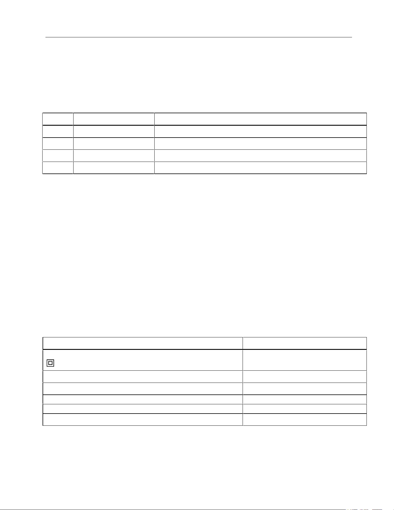
Table 6. Replacement Parts and Accessories
Description Fluke Part Number
Test lead assembly
Replace only with Fluke double-insulated leads.
648029
Battery door 1626588
Battery door screw 1618578
AA battery, 1.5 V, carbon-zinc (2 required) 650181
AA battery, 1.5 V, alkaline (2 required) 376756
T5-600/T5-1000 Electrical Tester Instruction Sheet (English) 1629509
1.888.610.7664 sales@GlobalTestSupply.com
Fluke-Direct.com
Loading ...