
PN 686953
March 1998 Rev.1, 9/01
1998-2001 Fluke Corporation. All rights reserved. Printed in U.S.A. Product names are trademarks of their respective companies.
T5-600/T5-1000
Electrical Tester
Service Information
Introduction
This service information sheet provides the following information for the T5-600 and T5-1000 Electrical
Testers (hereafter referred to as "the tester").
• Safety information
• Parts and service information
• Specifications
• Cleaning procedure
• Required equipment
• Performance tests
• Parts and accessories list
• Battery replacement procedure
For operating instructions, refer to the T5-600/T5-1000 Electrical Tester Instruction Sheet.
Safety Information
Warning
To avoid possible electric shock or personal injury, follow these guidelines:
• Do not use the tester if it is damaged or operating abnormally. Protection
may be impaired.
• Before each use:
• Make sure the battery door is closed and latched.
• Inspect the tester and test leads. Look for cracks, missing plastic, exposed
metal, or damaged insulation. Replace damaged test leads before using the
tester.
• Verify the tester’s operation by measuring a known voltage.
• Replace the batteries as soon as the low battery indicator (M) appears.
• Do not use the tester around explosive gas, vapor or dust.
• Do not apply more than the rated voltage, as marked on the tester, between
terminals or between any terminal and earth ground.
• Refer servicing to qualified personnel.
• Use caution when working above 30 V ac rms, 42 V ac peak, or 60 V dc.
• When using the probes, keep your fingers behind the finger guards on the
probes.
• Connect the common test lead before you connect the live test lead.
Disconnect the live test lead first.
• The display will not display hazardous voltages in display hold. The voltage
indicator LED (
) continues to operate.
®
1.888.610.7664 sales@GlobalTestSupply.com
Fluke-Direct.com

T5-600/T5-1000
Electrical Tester
2
Parts and Service
The tester is warranted to be free from defects in material and workmanship for two years, while under normal
use. Parts and repairs are warranted for 90 days. For the complete warranty statement, refer to the
T5-600/T5-1000 Electrical Tester Instruction Sheet.
Specifications
Accuracy is specified for one year after calibration, at 18 °C to 28 °C (64 °F to 82 °F) with relative humidity
to 90 %. AC conversions are ac-coupled, average responding, and calibrated to the rms value of a sine wave
input. Accuracy specifications are given as follows:
±([ % of reading] + [number of least significant digits])
Temperature coefficient of 0.1 x (specified accuracy)/ °C for <18 °C or >28 °C (<64.4 °F or >82.4 °F)
Serial Numbers 79560000 and Above
General Specifications
Calibration One-year calibration cycle.
Maximum Voltage
Between any Terminal
and Earth Ground
T5-600: 600 V rms, Overvoltage Category III, Pollution Degree 2
T5-1000: 1000 V rms, Overvoltage Category III, 600 V RMS, OverVoltage Category IV,
Pollution Degree 2
Maximum Voltage
Between Current Fork
and Earth Ground
T5-600 and T5-1000: 1000 V rms, Overvoltage Catergory III, also 600 V rms, Overvoltage
Category IV, Pollution Degree 2, (This dual rating applies to the current fork only.)
Temperature Operating: -10 °C to +50 °C (14 °F to 122 °F); Storage: -30 °C to +60 °C (-22 °F to +140 °F)
Altitude Operating: 2000 m (6562 ft); Storage: 10,000 m (32808 ft)
Relative Humidity 0 % to 95 %, 5 °C to 30 °C (41 °F to 86°F); 0 % to 75 %, 30 °C to 40 °C (86 °F to 104 °F);
0 % to 45 %, 40 °C to 50 °C (104 °F to 122 °F)
Battery Type and Life AA (2); 360 hours continuous with alkaline; 125 hours continuous with zinc chloride
Shock, Vibration 1 m drop at -10 °C to + 50 °C (14 °F to 122 °F) per ANSI/ISA-S82.01-1994 and EN 61010-1
1995. Random vibration per MIL-PRF-28800F for a Class 2 instrument
(5 Hz to 55 Hz, 3 g maximum)
Surge Protection T5-600: 6 kV per IEC 61010, T5-1000: 8 kV per IEC 61010
Enclosure Rating IP 52 per IEC 60529, no vacuum applied
1.888.610.7664 sales@GlobalTestSupply.com
Fluke-Direct.com
Service Information
Serial Numbers 79559999 and Below
3
General Specifications (continued)
RF Field Specification 0.5 % full scale + (specified accuracy) at 3 V/m
Safety Complies with ANSI/ISA-S82.01-94, UL Classified to IEC 61010, CSA/CAN C22.2 No.1010.1-
92, and EN61010-1 1995.
EMC EN 61326
Certifications
In accordance with IEC 61010-1 54CJ
Resolution and Accuracy
Function T5-600 Range T5-1000 Range Resolution Accuracy
K 600 V rms 1000 V rms 1 V ±(1.5 % + 2 digits)
L 600 V 1000 V 1 V ±(1 % + 1 digit)
? 100.0 A 100.0 A 0.1 A ±(3 % + 3 digits)
e 1000 Ω 1000 Ω 1 Ω±(1 % + 2 digits)
Input Characteristics
Input Protection
Function T5-600 T5-1000
Input impedance (nomial
K
600 V rms 1000 V rms 1 MΩ, <100 pF ac-coupled
L
600 V rms 1000 V rms 1 MΩ, <100 pF
e
600 V rms 1000 V rms
Open Circuit Test Voltage Short Circuit Current
e 1.65 V dc (nominal) <600 µA
CAT III protects against transients in a fixed equipment installation such as a distribution panel, and lighting systems in
large buildings.
CAT IV protects against transients from a primary supply such as an electricity meter or an overhead or underground utility
service.
Serial Numbers 79559999 and Below
General Specifications
Calibration One-year calibration cycle.
Maximum Voltage
Between any Terminal
and Earth Ground
T5-600: 600 V rms, Overvoltage Category III
T5-1000: 1000 V rms, Overvoltage Category III
Temperature Operating: -10 °C to +50 °C (14 °F to 122 °F); Storage: -30 °C to +60 °C (-22 °F to +140 °F)
Altitude Operating: 2000 m (6562 ft); Storage: 10,000 m (32808 ft)
Relative Humidity 0 % to 95 %, 5 °C to 30 °C (41 °F to 86°F); 0 % to 75 %, 30 °C to 40 °C (86 °F to 104 °F);
0 % to 45 %, 40 °C to 50 °C (104 °F to 122 °F)
Battery Type and Life AA (2); 400 hours continuous with alkaline; 200 hours continuous with zinc chloride
1.888.610.7664 sales@GlobalTestSupply.com
Fluke-Direct.com
T5-600/T5-1000
Electrical Tester
4
General Specifications (continued)
Shock, Vibration 1 m drop at 15 °C to 35 °C (59 °F to 95 °F) per ANSI/ISA-S82.01-1994 and EN 61010-1 1993.
Sinusoidal vibration per MIL-PRF-28800F for a Class 2 instrument
(5 Hz to 55 Hz, 3 g maximum)
Surge Protection T5-600: 6 kV per IEC 1010-1, 1990-09: T5-1000: 8 kV per IEC 1010-1, 1990-09
Enclosure Rating IP 52 per IEC 60529, no vacuum applied
RF Field Specification 0.5 % full scale + (specified accuracy) at 3 V/m
Safety Complies with ANSI/ISA-S82.01-94 for use in overvoltage category III (CAT III) locations,
UL3111, CSA/CAN C22.2 No.1010.1-92, and EN61010-1 1993.
EMC EN 50081-1, EN 50082-1
Certifications
Resolution and Accuracy
Function T5-600 Range T5-1000 Range Resolution Accuracy
K 600 V rms 1000 V rms 1 V ±(1.5 % + 2 digits)
L 600 V 1000 V 1 V ±(1 % + 1 digit)
? 100.0 A 100.0 A 0.1 A ±(3 % + 3 digits)
e 1000 Ω 1000 Ω 1 Ω±(1 % + 2 digits)
Input Characteristics
Input Protection
Function T5-600 T5-1000
Input impedance (nomial
K
600 V rms 1000 V rms 1 MΩ, <100 pF ac-coupled
L
600 V rms 1000 V rms 1 MΩ, <100 pF
e
600 V rms 1000 V rms
Open Circuit Test Voltage Short Circuit Current
e 2.4 V dc (nominal) <600 µA
CAT III protects against transients in a fixed equipment installation such as a distribution panel, and lighting systems in
large buildings.
CAT IV protects against transients from a primary supply such as an electricity meter or an overhead or underground utility
service.
Cleaning the Tester
WWarning
To avoid electric shock or damage to the tester, never allow water inside the
case. To avoid damaging the tester’s case, never use solvents on the tester.
If the tester requires cleaning, wipe it down with a cloth that is lightly dampened with water or a mild
detergent. Do not use aromatic hydrocarbons, chlorinated solvents, or methanol-based fluids when wiping
down the tester.
1.888.610.7664 sales@GlobalTestSupply.com
Fluke-Direct.com

Service Information
Equipment Required for Performance Tests
5
Equipment Required for Performance Tests
The following equipment is required for performance tests:
• Fluke 5500A Multi-Product Calibrator, or equivalent
• 0 V to 5 V adjustable dc power supply
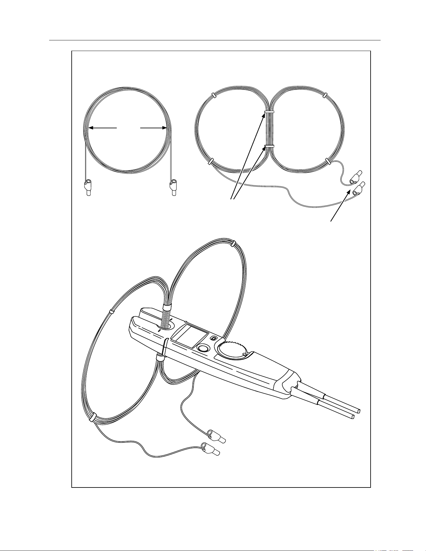
• Approximately 8 m (26 ft) of #14 single-conductor magnet wire wound into a butterfly-shaped coil.
Figure 1 shows how to make the coil.
Performance Tests
Use the following procedures to verify the tester’s performance. If the tester fails any of the tests, return it to
Fluke for calibration or repair.
Testing the AC Current Function
The tests in this section require the butterfly coil shown in Figure 1. Note that the 10 conductors in the middle
of the coil cause the tester to read 10 times more current than the calibrator supplies.
1. Put one edge of the butterfly coil in a vice to hold the coil during testing.
2. Set the calibrator to the current and frequency given in Step 1 of Table 1.
3. Connect the butterfly coil to the calibrator.
4. Set the tester to the amperage function.
5. Place the tester’s current fork around the middle of the coil so that the alignment marks are centered and
perpendicular to the wire bundle, as shown in Figure 1.
6. Verify that the tester reads within the display limits shown for Step 1 in Table 1.
7. Apply the currents and verify the tester’s readings for the remaining steps in Table 1.
Table 1. AC Current Tests
Step Calibrator output T5-600/T5-1000 Display Limits
1 10 A, 60 Hz 96.7 to 103.3
2 10 A, 45 Hz 96.7 to 103.3
3 0.5 A, 45 Hz 4.5 to 5.5
1.888.610.7664 sales@GlobalTestSupply.com
Fluke-Direct.com
T5-600/T5-1000
Electrical Tester
6
21 cm
(~8.25")
10 turns of #14
single-conductor
magnet wire
Separate into two 5-turn coils.
Use cable ties to
hold coils together
Connect to Calibrator
Mount Banana
plugs on wire end
qp7f.eps
Figure 1. Making the Butterfly Coil
1.888.610.7664 sales@GlobalTestSupply.com
Fluke-Direct.com

Service Information
Performance Tests
7
Testing the Voltage Functions
The tests in this section check the following voltage functions:
• Automatic selection of ac or dc voltage mode
• Correct operation of the hazardous voltage indicator
• Correct operation of the HOLD function
Perform the tests as follows:
1. Set the calibrator to the T5-600 or T5-1000 test voltage given in Table 2.
2. Apply the voltage to the tester. Verify that the tester reads within the display limits shown.
3. Apply the voltages and verify the tester’s readings for the steps in Tables 3 and 4.
Table 2. AC Voltage Test
T5-600 T5-1000
Calibrator Output
T5-600 Display Limits
(AC annunciator ON) Calibrator Output
T5-1000 Display Limits
(AC annunciator ON)
600 V, 60 Hz 589 to 611 1000 V, 60 Hz 983 to 1017
Table 3. DC Voltage Tests
T5-600 T5-1000
Step Calibrator Output
T5-600 Display Limits
(DC annunciator ON) Calibrator Output
T5-1000 Display Limits
(DC annunciator ON)
1 600 V dc 593 to 607 1000 V dc 989 to 1011
2 -60 V dc -58 to -62 -100 V dc -98 to -102
3 1.0 V dc 1 ±1* 1.0 V dc 1 ±1*
4 -1.0 V dc -1 ±1* -1.0 V dc -1 ±1*
* Verify that the ac annunciator is OFF.
Table 4. Hazardous Voltage LED and HOLD Function Tests
Step Calibrator Output T5-600/T5-1000 Display Indicators
1 12 V, 60 Hz Reading: 12 ± 1
Hazardous voltage LED OFF
2 12 V, 60 Hz
Tap tester’s HOLD button
Reading: 12 ± 1
Hazardous voltage LED OFF
HOLD indicator ON
3 +38 V dc Reading: 12 ±1
Hazardous voltage LED ON
HOLD indicator ON
1.888.610.7664 sales@GlobalTestSupply.com
Fluke-Direct.com
T5-600/T5-1000
Electrical Tester
8
Resistance and Continuity Function Tests
1. Set the calibrator to the resistance given in Step 1 of Table 5.
2. Apply the resistance to the tester. Verify that the tester reads within the display limits shown.
3. Apply the resistances and verify the tester’s responses for the remaining steps in Table 5.
Table 5. Resistance and Continuity Tests
Step Calibrator Output T5-600/T5-1000 Display Limits and Beeper Responses
11 kΩ 988 to 1012
2 26 Ω Beeper ON
3 300 Ω Beeper OFF
40 Ω -2 to 2, Beeper ON
Low Battery Indicator Test
The following procedure verifies correct operation of the low battery indicator.
1. Remove the tester’s batteries.
2. Set the dc power supply to 3.0 V. Apply this voltage to the tester’s battery terminals.
3. Set the calibrator to 1 kΩ. Apply this resistance to the tester’s probes.
4. Slowly decrease the dc voltage just until the tester’s low battery indicator (M) turns on.
5. Verify that the tester reads 1000 ±12 counts (988 to 1012).
6. Disconnect the calibrator and the dc power supply. Reinstall the tester’s batteries.
Parts and Accessories
Tables 6 shows the replacement parts and accessories available from Fluke for the T5-600 and T5-1000
Electrical Testers.
Table 6. Replacement Parts and Accessories
Description Fluke Part Number
Test lead assembly
Replace only with Fluke double-insulated leads.
648029
Battery door 1626588
Battery door screw 1618578
AA battery, 1.5 V, carbon-zinc (2 required) 650181
AA battery, 1.5 V, alkaline (2 required) 376756
T5-600/T5-1000 Electrical Tester Instruction Sheet (English) 1629509
1.888.610.7664 sales@GlobalTestSupply.com
Fluke-Direct.com
Service Information
Battery Replacement
9
Table 6. Replacement Parts and Accessories (continued)
Description Fluke Part Number
T5-600/T5-1000 Electrical Tester Instruction Sheet (International) 1621978
H5 Belt Holster Accessory
TP1 Probe Set, Flat Blade
Accessory
TP4 Probe Set, 4 mm Round
Accessory
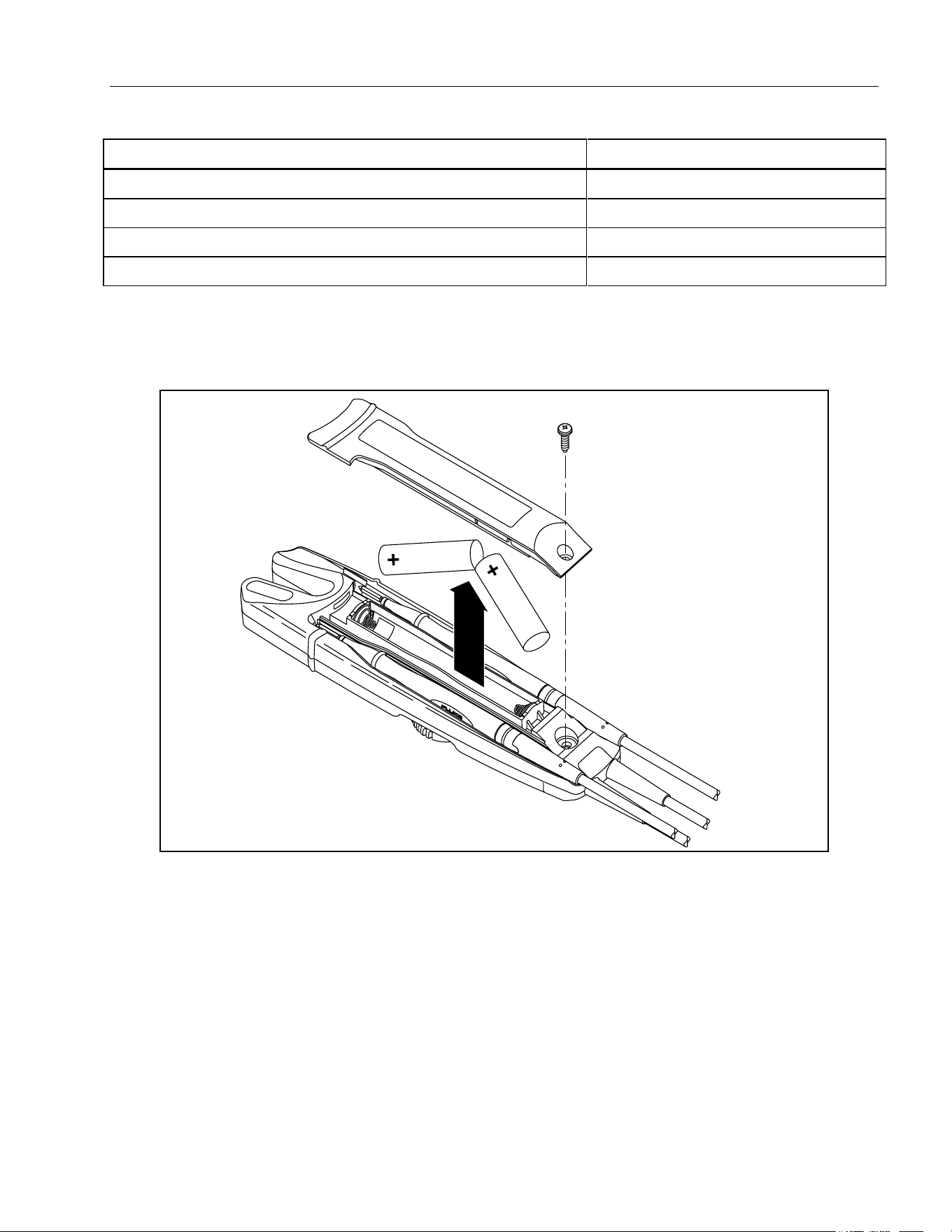
Battery Replacement
Figure 2 shows how to replace the batteries. Observe the polarity markings inside the battery compartment.
qp1.eps
Figure 2. Replacing the Batteries
1.888.610.7664 sales@GlobalTestSupply.com
Fluke-Direct.com