© 2022 GeoVision, Inc. All rights reserved.
Under the copyright laws, this manual may not be copied, in whole or in part, without
the written consent of GeoVision.
Every effort has been made to ensure that the information in this manual is accurate.
GeoVision, Inc. makes no expressed or implied warranty of any kind and assumes no
responsibility for errors or omissions. No liability is assumed for incidental or
consequential damages arising from the use of the information or products contained
herein. Features and specifications are subject to change without notice.
GeoVision, Inc.
9F, No. 246, Sec. 1, Neihu Rd.,
Neihu District, Taipei, Taiwan
Tel: +886-2-8797-8377
Fax: +886-2-8797-8335
http://www.geovision.com.tw
Trademarks used in this manual: GeoVision, the GeoVision logo and GV series
products are trademarks of GeoVision, Inc. Windows is the registered trademark of
Microsoft Corporation.
February 2022
Scan the following QR codes for product warranty and technical support policy:
[Warranty] [Technical Support Policy]
i
Preface
Welcome to the GV-SNVR System User’s Manual.
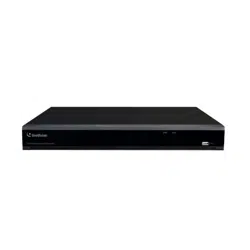
The GV-SNVR system has a series of models designed to meet different needs.
This manual is designed for the following models:
Models
GV-SNVR0400F
GV-SNVR0411
GV-SNVR0412
GV-SNVR0811
GV-SNVR0812
GV-SNVR1600
GV-SNVR1611
GV-SNVR1612
Caution
The GV-SNVR system is designed for indoor use only.

ii
Contents
Chapter 1 Introduction........................................................................................... 1
1.1 Features........................................................................................................2
1.2 Models ..........................................................................................................3
1.3 Packing List and Package.............................................................................3
1.3.1 GV-SNVR Single Package ....................................................................................... 4
GV-SNVR0400F ...................................................................................................4
GV-SNVR0411......................................................................................................4
GV-SNVR0412 .....................................................................................................5
GV-SNVR0811......................................................................................................5
GV-SNVR0812 .....................................................................................................6
GV-SNVR1600 .....................................................................................................6
GV-SNVR1611......................................................................................................7
GV-SNVR1612 .....................................................................................................7
1.3.2 GV-SNVR Bundled Package ................................................................................... 8
GV-SNVR0400F ...................................................................................................8
1.4 Compatible Products and System Requirements.........................................9
1.4.1 Supported GV-IP Cameras .......................................................................9
1.4.2 Supported GeoVision Applications..........................................................10
1.4.3 System Requirements.............................................................................12
1.5 Optional Accessories .................................................................................13
1.6 Overview....................................................................................................14
1.6.1 GV-SNVR0411 Front View ......................................................................14
1.6.2 GV-SNVR0411 Rear View.......................................................................15
1.6.3 GV-SNVR0400F Front View....................................................................16
1.6.4 GV-SNVR0400F Rear View ....................................................................17
1.6.5 GV-SNVR0811 Front View ......................................................................18
1.6.6 GV-SNVR0811 Rear View.......................................................................19
1.6.7 GV-SNVR1600 Front View......................................................................20
1.6.8 GV-SNVR1600 Rear View ......................................................................21
1.6.9 GV-SNVR1611 Front View ......................................................................22
1.6.10 GV-SNVR1611 Rear View.....................................................................23
1.6.11 GV-SNVR0812 Front View ....................................................................24
1.6.12 GV-SNVR0812 Rear View ....................................................................25
1.6.13 GV-SNVR0412 Front View....................................................................26
1.6.14 GV-SNVR0412 Rear View ....................................................................27
1.6.15 GV-SNVR1612 Front View....................................................................28
1.6.16 GV-SNVR1612 Rear View ....................................................................29

iii
Chapter 2 Getting Started.................................................................................... 30
2.1 Installation..................................................................................................30
2.1.1 GV-SNVR0411 ........................................................................................30
2.1.2 GV-SNVR0811 ...........................................................................................................32
2.1.3 GV-SNVR0400F ........................................................................................................34
2.1.4 GV-SNVR1600........................................................................................36
2.1.5 GV-SNVR1611 / 1612..............................................................................................38
2.1.6 GV-SNVR0412 / 0812..............................................................................................40
2.2 Connecting GV-SNVR................................................................................42
2.2.1 Network Connection for GV-SNVR1600 .................................................47
2.2.2 Accessing GV-SNVR ..............................................................................48
2.3 Setting Up IP Cameras ..............................................................................49
2.3.1 Automatically Setting Up IP Cameras .....................................................49
2.3.2 Manually Connecting GV-IP Cameras ....................................................51
2.3.3 Manually Connecting Third-Party IP Cameras ........................................52
2.3.4 Changing Camera IP Address and Assigning Channels .........................54
2.4 Formatting Hard Drive................................................................................55
2.5 Main Screen...............................................................................................57
2.6 Enabling Recording....................................................................................59
2.7 Playing Back Video ....................................................................................59
2.8 Live Monitoring...........................................................................................60
2.8.1 Snapshots...............................................................................................60
2.8.2 Audio.......................................................................................................61
2.8.3 PTZ Control.............................................................................................63
2.8.4 Digital PTZ Function ...............................................................................64
2.8.5 Fisheye Dewarping .................................................................................65
2.8.6 Image Orientation ...................................................................................66
Chapter 3 System Configuration ........................................................................ 67
3.1 Camera .......................................................................................................67
3.1.1 GV-IP Camera Settings...........................................................................67
3.1.2 Third-Party IP Camera Settings (ONVIF) ................................................70
3.2 Record ........................................................................................................72
3.3 Network.......................................................................................................73
3.3.1 WAN / LAN..............................................................................................73
3.3.2 WiFi.........................................................................................................76
3.3.3 DDNS......................................................................................................77
3.3.4 E-Mail......................................................................................................78

iv
3.3.5 Web Server .............................................................................................79
3.4 Storage .......................................................................................................80
3.5 Display ........................................................................................................80
3.6 Service........................................................................................................82
3.6.1 Connecting to GV-Center V2 and GV-Vital Sign Monitor.........................82
3.6.2 Regulating People Flow with GV-IP Cameras.........................................83
3.6.3 Connecting to GV-Eye ............................................................................84
3.6.4 Connecting to GV-Cloud Center..............................................................85
3.7 Event...........................................................................................................86
3.8 System........................................................................................................88
3.9 Account.......................................................................................................91
Chapter 4 Video Playback ................................................................................... 93
4.1 Timeline Player ...........................................................................................93
4.2 Recording Export .......................................................................................95
Chapter 5 Remote Access to GV-SNVR ............................................................. 96
5.1 Accessing through IE Browser ....................................................................97
5.1.1 Live View Screen ....................................................................................98
5.1.2 Camera Settings via Web .....................................................................100
5.1.3 Snapshots of Live Video .......................................................................101
5.1.4 Picture-in-Picture View..........................................................................102
5.1.5 Picture-and-Picture View.......................................................................103
5.1.6 Digital PTZ Control................................................................................104
5.1.7 Fisheye View .........................................................................................105
5.2 Accessing through SNVR Viewer..............................................................108
5.2.1 Live View through SNVR Viewer...........................................................109
5.3 Accessing through Mobile Devices ........................................................... 111
5.4 Accessing through GV-Edge Recording Manager..................................... 111
5.5 Accessing through GV-Control Center ...................................................... 112
5.6 Accessing through RTSP .......................................................................... 112
Chapter 6 Advanced Applications .....................................................................113
6.1 Advanced Options.................................................................................... 113
6.1.1 Upgrading System Firmware................................................................. 113
6.1.2 Safe Mode of GV-SNVR1611................................................................ 114
6.1.3 Backing Up and Restoring Settings ...................................................... 115
6.2 Using GV-IP Device Utility........................................................................ 116

v
6.2.1 Looking Up the IP Address.................................................................... 116
6.2.2 Accessing the Live View ....................................................................... 116
6.2.3 Upgrading System Firmware................................................................. 117
6.2.4 Backing Up and Restoring Settings ...................................................... 118
6.2.5 Restoring to Factory Default Settings ...................................................120
Appendix ............................................................................................................... 121
A. Tested and Supported Hard Disk Drives....................................................121
B. Live View Streaming ..................................................................................123
C. Supported Resolution by GV-SNVR..........................................................125
1
Chapter 1 Introduction
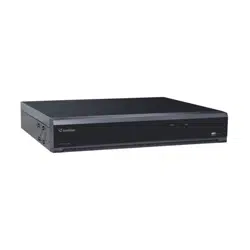
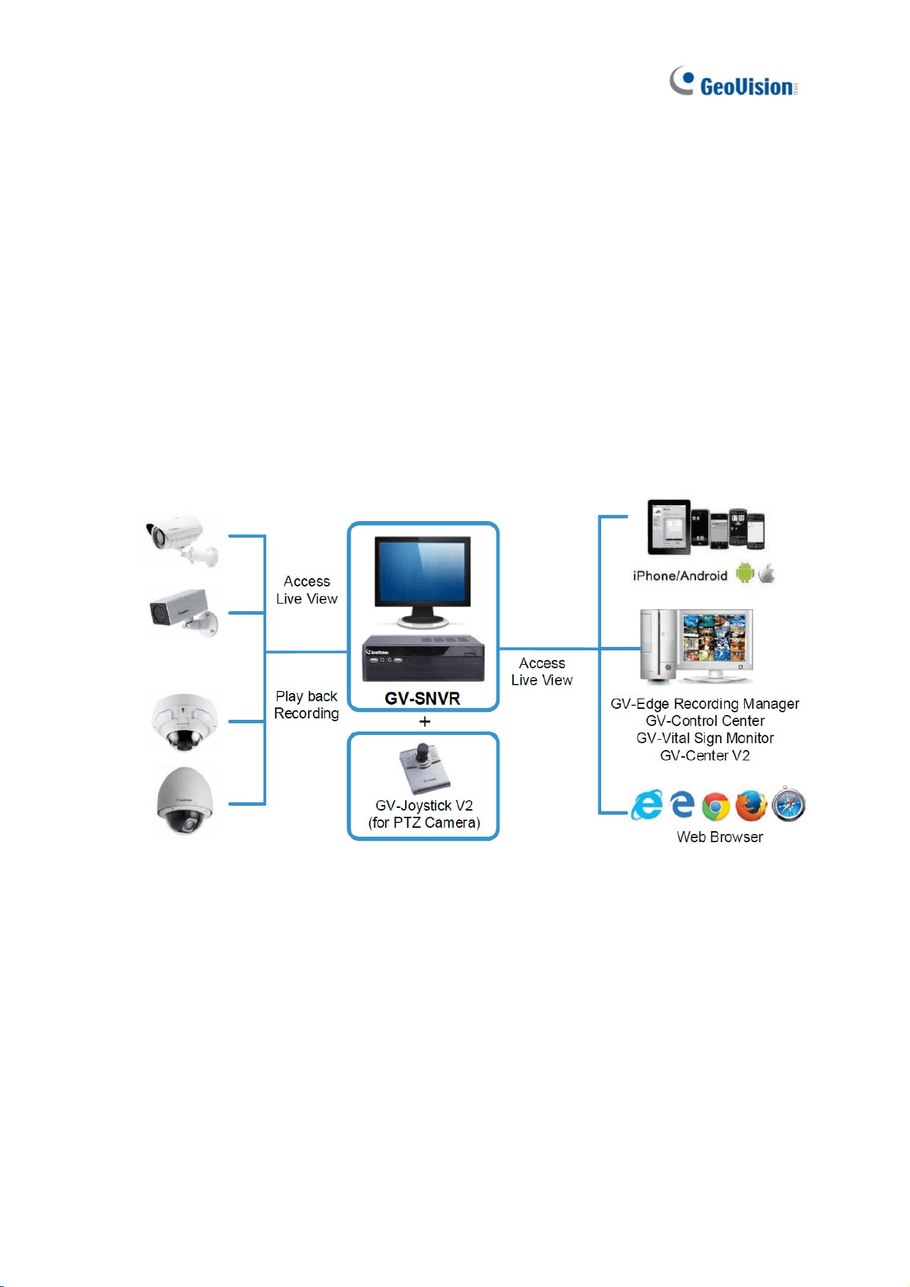
GV-SNVR is an H.264/H.265 Linux-embedded Standalone Network Video Recorder that
records video files directly to the internal hard drive, supporting up to 4 / 8 / 16 channels of IP
cameras for network surveillance. With the feature of a Full HD HDMI video output,
GV-SNVR eliminates the need of a separate PC to view and play back video images from the
unit. Its USB ports allow you to connect a USB flash drive to import or export system settings,
update firmware, save snapshot files and back up videos in AVI format.
Optionally, you can connect a GV-Joystick V2 to control connected PTZ cameras. In addition,
you can remotely access the live view and recorded videos through mobile devices, SNVR
Viewer or Web browsers with advanced video features.
Figure 1-1
Introduction
2
1
1.1 Features
˙ 4-Channel video recording (for GV-SNVR0400F / 0411 / 0412)
˙ 8-Channel video recording (for GV-SNVR0811 / 0812)
˙ 16-Channel video recording (for GV-SNVR1600 / 1611 / 1612)
˙ Automatic search and setup of IP cameras
˙ Support for third-party IP cameras through ONVIF and RTSP
(for GV-SNVR0411 / 0412 / 0811 / 0812 / 1611 / 1612)
˙ PoE for camera connection
Model
PoE
GV-SNVR0411
4-Port PoE (IEEE 802.3af)
GV-SNVR0412
4-Port PoE+ (IEEE 802.3at)
GV-SNVR0811 / 0812
8-Port PoE+ (IEEE 802.3at)
GV-SNVR1612
16-Port PoE (IEEE 802.3af)
GV-SNVR1611
16-Port PoE+ (IEEE 802.3at)
˙ Video Resolution
Model
Resolution
GV-SNVR0411 / 0412 / 0811
/ 0812
Up to 3840 x 2160 per channel *
GV-SNVR1611
Up to 4000 x 3000 per channel *
GV-SNVR1612
Up to 3840 x 2160 per channel *
GV-SNVR0400F
Up to 1920 x 1080 per channel *
GV-SNVR1600
Up to 2592 x 1944 for the first channel *
Up to 1920 x 1080 per channel
*
˙ Dual stream support
˙ Continuous, motion and scheduled recording
˙ Alarm-triggered recording for GV-SNVR0412 / 0812 / 1611 / 1612
˙ Timeline playback
˙ Multi-channel playback
˙ Display of HDD status and system temperature
˙ DST (Daylight Saving Time) support
˙ NTP (Network Time Protocol) support
˙ GeoVision DDNS server support
˙ E-mail notification for recording error and password retrieval
3
˙ Recording export
˙ Remote live view through Web browser
˙ PTZ control using GV-Joystick V2 or on-screen panel
˙ HDD Storage
Model Storage
GV-SNVR0411 / 0811
1 SATA HDD drawer (3.5”) for up to 8 TB storage
GV-SNVR0412 / 0812
1 SATA HDD drawer (3.5”) for up to 10 TB storage
GV-SNVR0400F
1 SATA HDD drawer (3.5”) for up to 4 TB storage
GV-SNVR1600
4 SATA HDD drawers (3.5”) for up to 16 TB storage
GV-SNVR1611 / 1612
2 SATA HDD drawers (3.5”) for up to 20 TB storage
˙ Smart device access (iOS and Android)
˙ Support for 14 languages (13 languages for GV-SNVR0400F / 1600)
˙ The resolutions of streams 1 and 2 both must meet the requirements
noted in Appendix C
1.2 Models
GV-SNVR has the following models:
GV-SNVR0400F
GV-SNVR0411
GV-SNVR0412
- Support 1 SATA HDD (3.5”)
- Record up to 4 IP channels
GV-SNVR0811
GV-SNVR0812
- Support 1 SATA HDD (3.5”)
- Record up to 8 IP channels
GV-SNVR1600
- Support 4 SATA HDD (3.5”)
- Record up to 16 IP channels
GV-SNVR1611
GV-SNVR1612
- Support 2 SATA HDD (3.5”)
- Record up to 16 IP channels
1.3 Packing List and Package
You can choose to purchase a GV-SNVR0400F / 0411 / 0412 / 0811 / 0812 / 1600 / 1611 /
1612 package or a GV-SNVR0400F bundled package, which includes 4 GV-Target IP
Cameras of your choice, and with or without a GV-PoE switch.
Introduction
4
1
1.3.1 GV-SNVR Single Package
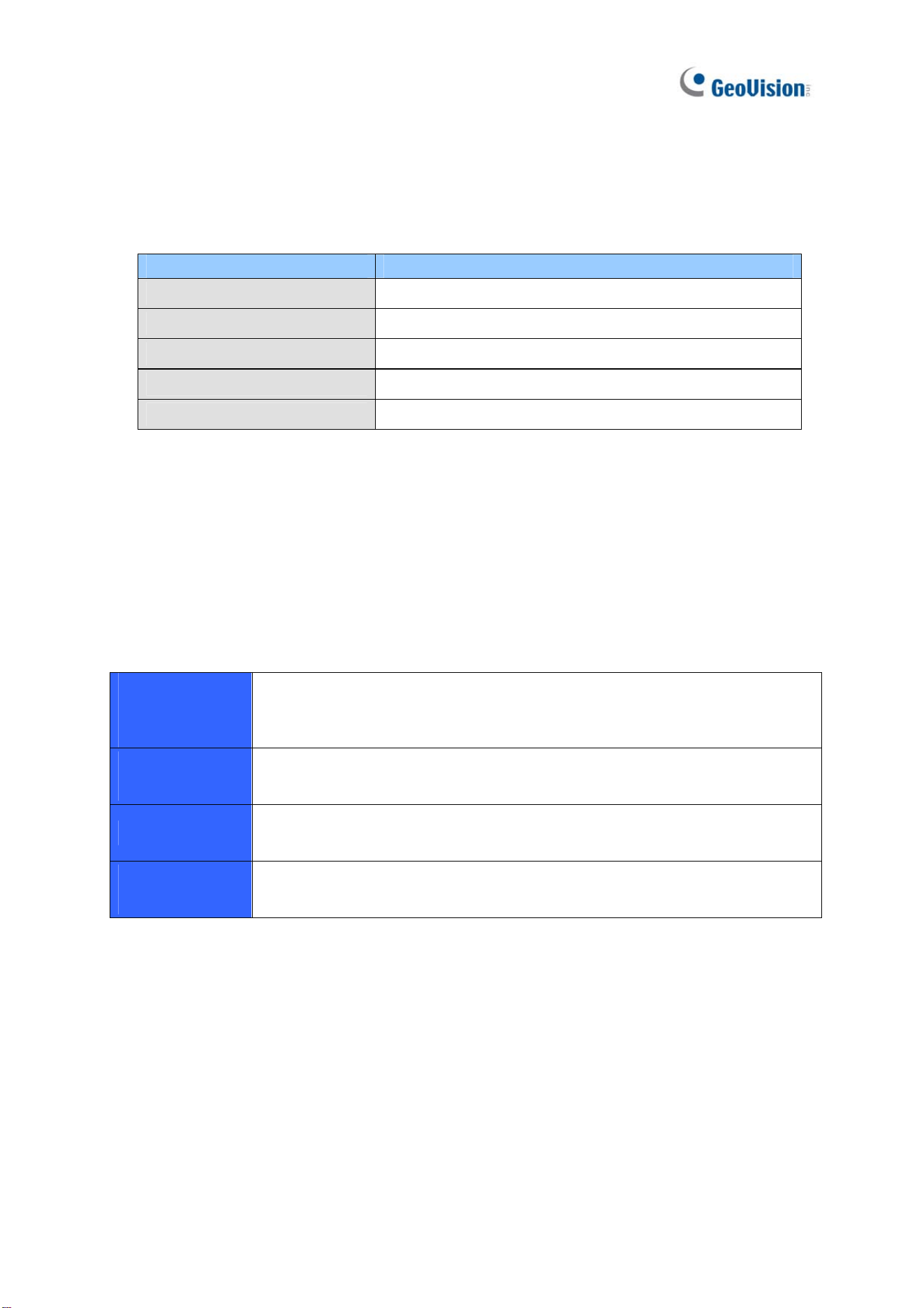
GV-SNVR0400F
1. GV-SNVR0400F
2. AC power cord
3. AC/DC adapter
(DC 19V, 3.42A, 65 W)
4. Screw x 6 (for HDD)
5. SATA cable
6. Download Guide
7. Quick Start Guide
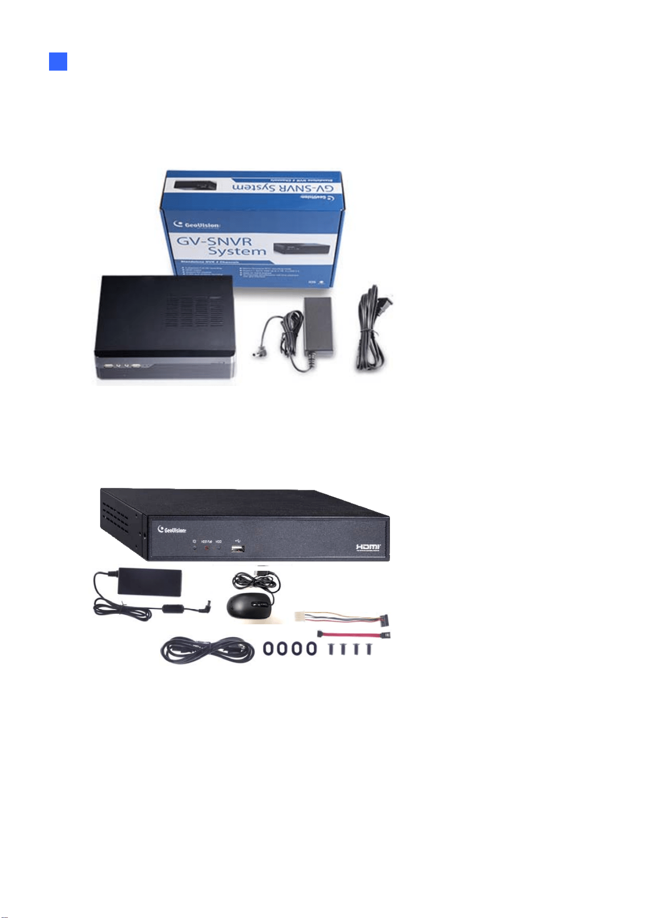
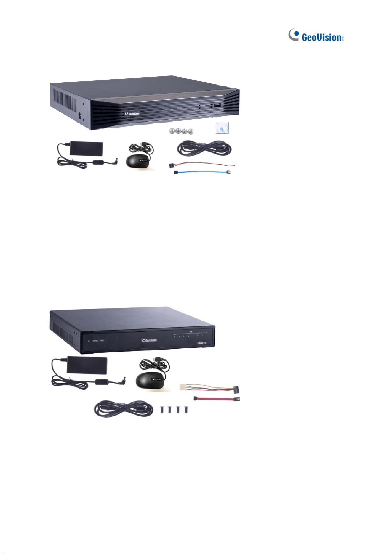
GV-SNVR0411
1. GV-SNVR0411
2. AC power cord
3. AC/DC adapter
(DC 52V, 1.38 A, 72 W)
4. SATA cable
5. HDD power cable
6. Screw x 4 (for HDD)
7. Rubber foot x 4 (for HDD)
8. USB mouse
9. Download Guide
5
GV-SNVR0412
1. GV-SNVR0412
2. AC Power cord
3. AC/DC adapter
(DC 48 V, 1.35 A, 65 W)
4. SATA cable
5. HDD power cable
6. Screw x 4 (for HDD)
7. USB mouse
8. Foam foot
9. Rack mount kit (2 L-shaped
brackets + 4 screws)
10. Download Guide
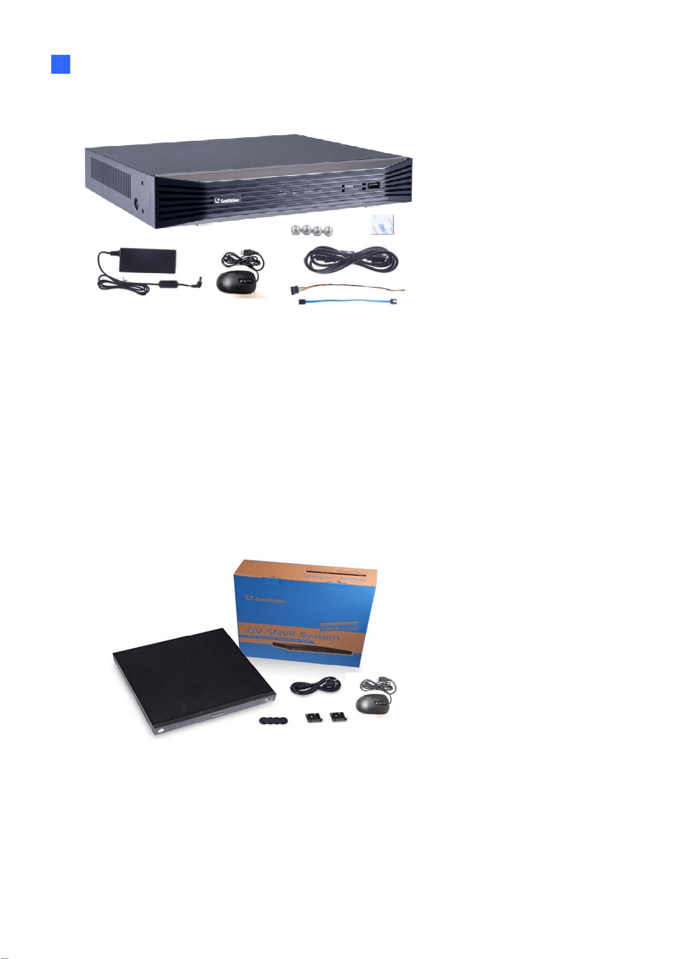
GV-SNVR0811
1. GV-SNVR0811
2. AC Power cord
3. AC/DC adapter
(DC 56V, 2.32 A, 130 W)
4. SATA cable
5. HDD power cable
6. Screw x 4 (for HDD)
7. USB mouse
8. Download Guide
Introduction
6
1
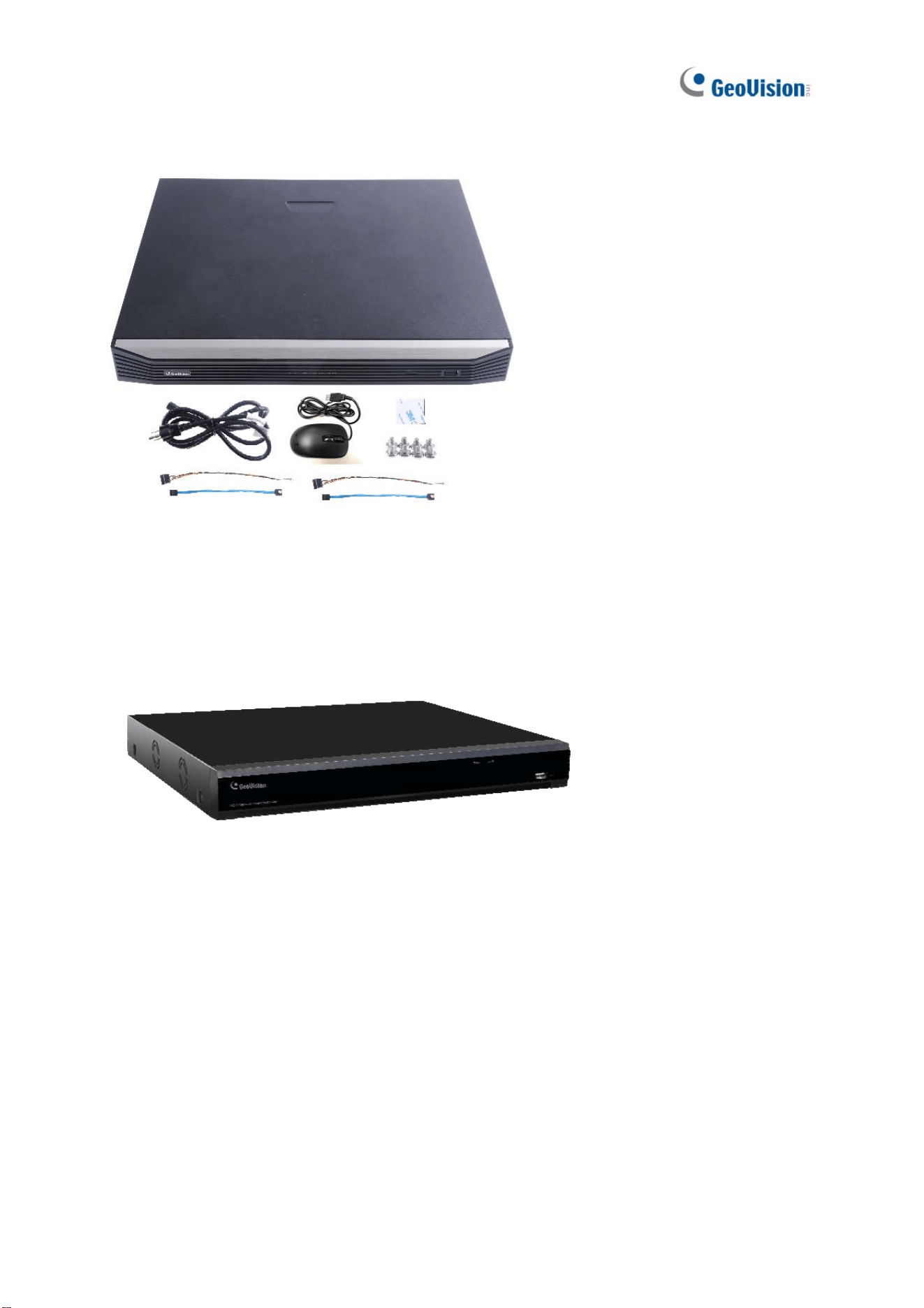
GV-SNVR0812
1. GV-SNVR0812
2. AC power cord
3. AC/DC adapter (DC 52V,
1.8A, 100W)
4. SATA cable
5. HDD power cable
6. Screw x 4 (for HDD)
7. Foam foot
8. USB mouse
9. Rack mount kit (2 L-shaped
brackets + 4 screws)
10. Download Guide
GV-SNVR1600
1. GV-SNVR1600
2. AC power cord
3. SATA cable x 4
4. HDD mounting bracket kit (4
pairs and 32 screws included)
5. Rack mount kit (2 L-shaped
brackets and 6 screws
included)
6. Rubber foot x 4
7. USB mouse
8. Download Guide
9. Quick Start Guide
7
GV-SNVR1611
1. GV-SNVR1611
2. AC power cord
3. SATA cable x 2
4. HDD power cable x 2
5. Screw x 8 (for HDD)
6. Foam foot
7. USB mouse
8. Download Guide
GV-SNVR1612
1. GV-SNVR1612
2. Power adapter
3. AC power cord
4. SATA cable x 2
5. HDD power cable x 2
6. Screw x 8 (for HDD)
7. Foam foot
8. USB mouse
9. Download Guide
Introduction
8
1
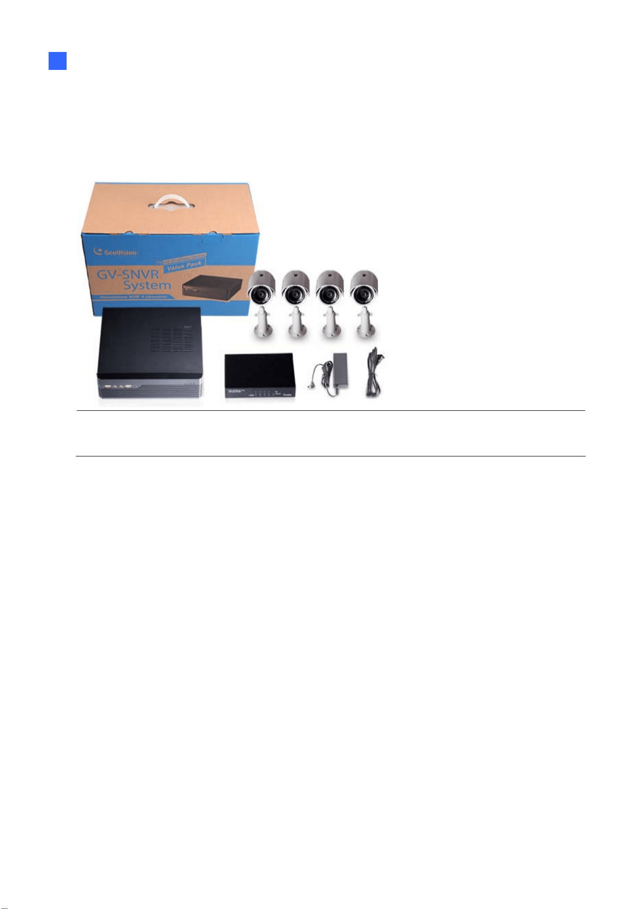
1.3.2 GV-SNVR Bundled Package
GV-SNVR0400F
1. GV-SNVR0400F package x 1
2. Target IP Camera x 4
3. GV-POE0400 x 1
Note: For the Target IP Camera, select any 4 models from GV-EBL1100 / 2100, GV-EBX1100 /
2100, GV-EDR1100 / 2100, GV-EFD1100 / 2100. Contact your dealer for more information.
9
1.4 Compatible Products and System Requirements
1.4.1 Supported GV-IP Cameras
GV-SNVR is compatible with the following GV-IP Cameras:
˙ GV-Target Series IP Cameras (Firmware V1.0 or later)
˙ GV-SD220/220-S (Firmware V1.04 or later)
˙ GV-UNFE2503 / UNP2500 (Firmware V2.11 or later)
˙ All other GV-IP Cameras EXCEPT for the models below:
GV-SNVR System Not Supported Models
SNVR0400F
SNVR1600
GV-ABD1300
GV-ABL Series / ADR Series / AVD Series / EBD Series / TBL
Series / TDR Series / TVD Series
GV-BX110/12201
GV-BL110
GV-EBL2101 / 2111 / 3101 (conditionally supported)
(*Note4)
GV-FD8700-FR
GV‐FER12203 / 12700
GV-Fisheye Cameras (conditionally supported)
(*Note3)
GV-MFD110
GV-PT110
GV-PTZ010D
GV-SD010 / 200 / 200-S / 2301 / 2322-IR / 2411 / 2722-IR /
3732-IR
GV-VD8700
GV-VR360
SNVR0411
SNVR0412
SNVR0811
SNVR0812
SNVR1611
SNVR1612
GV-BX110
GV-BL110
GV-FE520 / 521
GV-FER12203 / 12700
GV-MFD110
GV-PT110
GV-PTZ010D
GV-SD010

Introduction
10
1
Note: The live view of GV-SD200 / 200-S / 2411 / 2322-IR / 3732-IR can be accessed
through GV-SNVR0411 / 0811, but their PTZ control functions are only available on
GV-SNVR0411 firmware V2.61 or later and GV-SNVR0811 firmware V2.50 or later.
IMPORTANT:
1. GV-SNVR supports a recording frame rate of up to 30 fps.
2. GV-SNVR supports a total bandwidth of up to 50 Mbps for GV-SNVR0400F, 40 Mbps
for GV-SNVR0411, 24 Mbps for GV-SNVR0412, 80 Mbps for GV-SNVR0811, 48 Mbps
for GV-SNVR0812, 96 Mbps for GV-SNVR1612, 100 Mbps for GV-SNVR1600 and 320
Mbps for GV-SNVR1611.
3. GV-SNVR1600 can only connect to GV-Fisheye Cameras, except for GV-FER12203 /
12700, via channel 1 and does not support fisheye dewarping(
*).
4. GV-EBL2101 / 2111 / 3101 is only supported on channel 1 of GV-SNVR0400F (*).
5. Fisheye dewarping is only supported by GV-SNVR0411 / 0412 / 0811 / 0812. For
details, see 2.8.5 Fisheye Dewarping. GV-SNVR1611 V3.11 only supports fisheye
dewarping on GV-SNVR Viewer (V1.5.0001).
6. For supported IP cameras, the resolutions of stream 1 and 2 both must meet the
requirements noted in Appendix C.
1.4.2 Supported GeoVision Applications
GV-SNVR is compatible with the following applications:
For GV-SNVR0411 / 0811
˙ GV-Edge Recording Manager (Windows Version V1.2.0.0 or later)
˙ GV-Control Center (V3.4.0.0 or later)
˙ GV-Center V2 (V15.10 or later)
˙ GV-Vital Sign Monitor (V15.10 or later)
˙ GV-Cloud Center (V1.0 or later)
˙ GV-Eye (V2.3 or later)

11
For GV-SNVR0412 / 0812
˙ GV-Edge Recording Manager (Windows Version V1.4.0.3 / V1.4.0.0 or later)
˙ GV-Control Center (V3.6.0 or later)
˙ GV-Center V2 (V18.2 +
patch or later)
˙ GV-Vital Sign Monitor (V17.1 or later)
˙ GV-Cloud Center (V1.0 or later)
˙ GV-Eye (V2.7.2 or later)
For GV-SNVR1612
˙ GV-Edge Recording Manager (Windows Version V2.1.0 or later)
˙ GV-Control Center (V3.4.0 or later)
˙ GV-Center V2 (V18.2 +
patch
or later)
˙ GV-Vital Sign Monitor (V16.11 or later)
˙ GV-Cloud Center (V1.0 or later)
˙ GV-Eye (V2.5.1 or later)
For GV-SNVR1611
˙ GV-Center V2 (V18.2 +
patch or later)
˙ GV-Vital Sign Monitor (V16.11 or later)
˙ GV-Cloud Center (V1.0 or later)
˙ GV-Eye (V2.5.1 or later)
For GV-SNVR0400F / 1600
˙ GV-Edge Recording Manager (Windows Version V1.1.0.0 or later)
˙ GV-Control Center (V3.3.0.0 or later)
˙ GV-Center V2 (V15.10 or later)
˙ GV-Vital Sign Monitor (V15.10 or later)
˙ GV-Eye (V2.0 or later)

Introduction
12
1
1.4.3 System Requirements
Recommended Hard Disks
For system efficiency, it is recommended to use enterprise-level hard disk drives instead of
desktop-level or green HDD. For tested hard disk drives, see Appendix.
Note: GV-SNVR does not support 2.5” SATA HDD.
Supported Web Browsers
Internet Explorer 8 or later (10 or later for GV-SNVR0412 / 0812)
Google Chrome
Mozilla Firefox
Safari (Only for GV-SNVR0411 / 0412 / 0811 / 0812 / 1611 / 1612)
Microsoft Edge (Only for GV-SNVR0411 / 0412 / 0811 / 0812 / 1611 / 1612)
13
1.5 Optional Accessories
Optional devices can expand your GV-SNVR’s capabilities and versatility. Contact your
dealer for more information.
GV-Joystick V2
GV-Joystick V2 facilitates PTZ camera control. It can be plugged
into GV-SNVR for independent use to empower the operation of
PTZ cameras.
GV-POE Switch
GV-POE Switch is designed to provide power along with network
connection for IP devices. GV-POE Switch is available in various
models with different numbers and types of ports.
GV-WiFi Adaptor V2
For GV-SNVR0411 / 0811 only, GV-WiFi Adaptor V2 is designed to
connect GV-IP devices to a wireless network. This product supports
2.4 GHz and 5 GHz wireless connection.
Slide Rail Kit
The Slide Rail Kit is used to mount a rail for GV-SNVR1600 in a 19”
cabinet.
Introduction
14
1
1.6 Overview
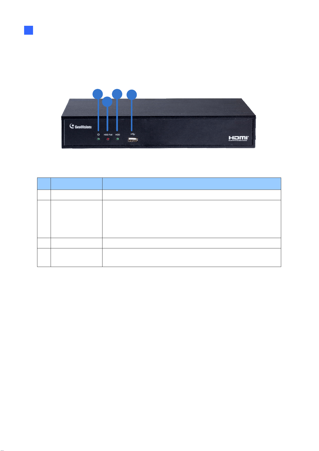
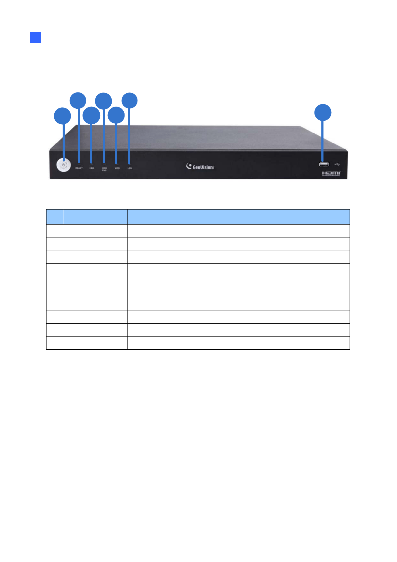
1.6.1 GV-SNVR0411 Front View
4
3
2
1
Figure 1-2
No. Name Function
1
Power LED Shows constant green when power is supplied.
2
HDD Error LED
Shows constant red when:
˙ No hard drive is installed.
˙ The hard drive is not formatted.
˙ The hard drive fails.
3
HDD LED Blinks green when the HDD is writing or reading data.
4
USB 2.0 Port
Connects to a keyboard, mouse, USB flash drive, GV-WiFi Adaptor
V2 or GV-Joystick V2.
15
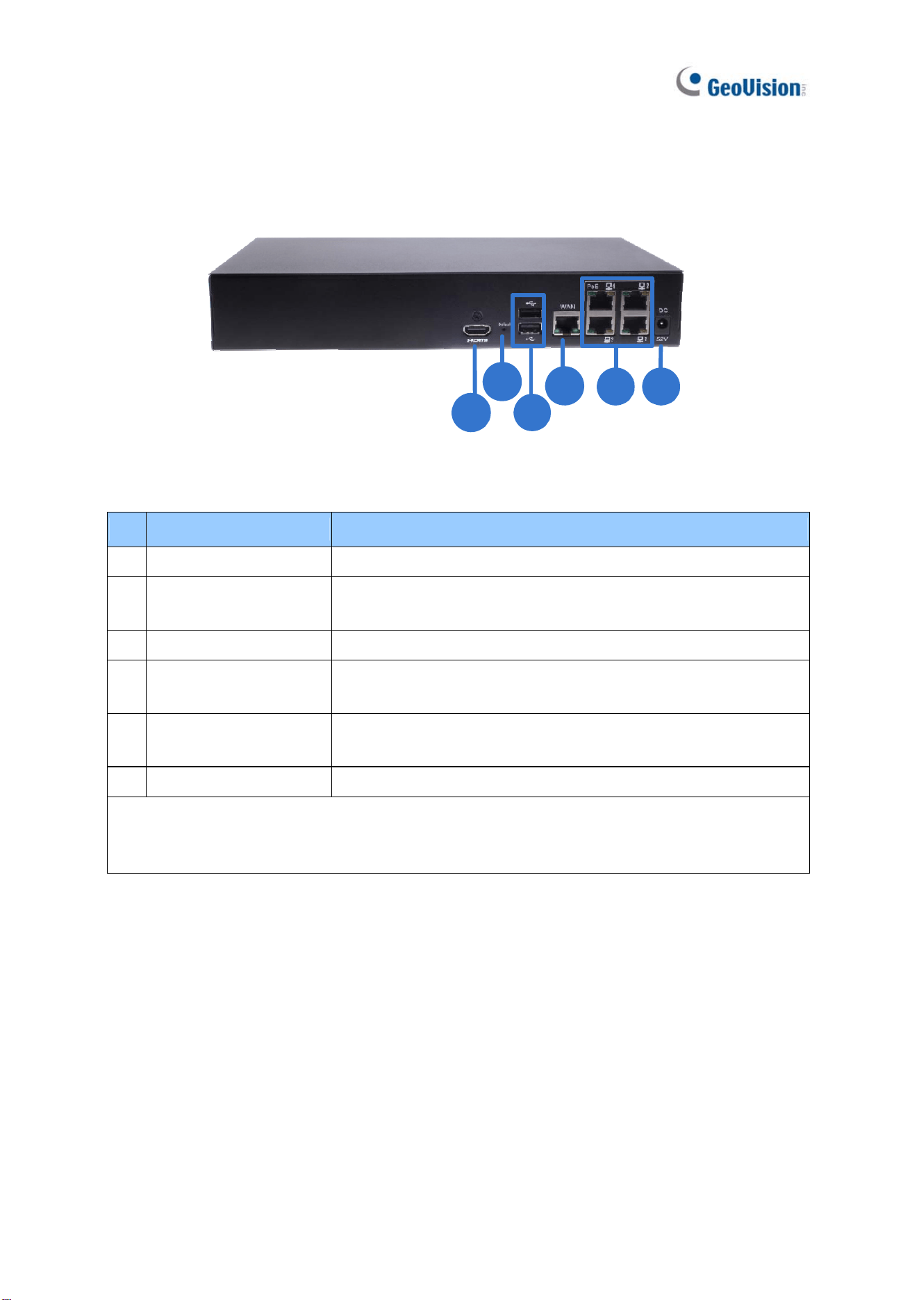
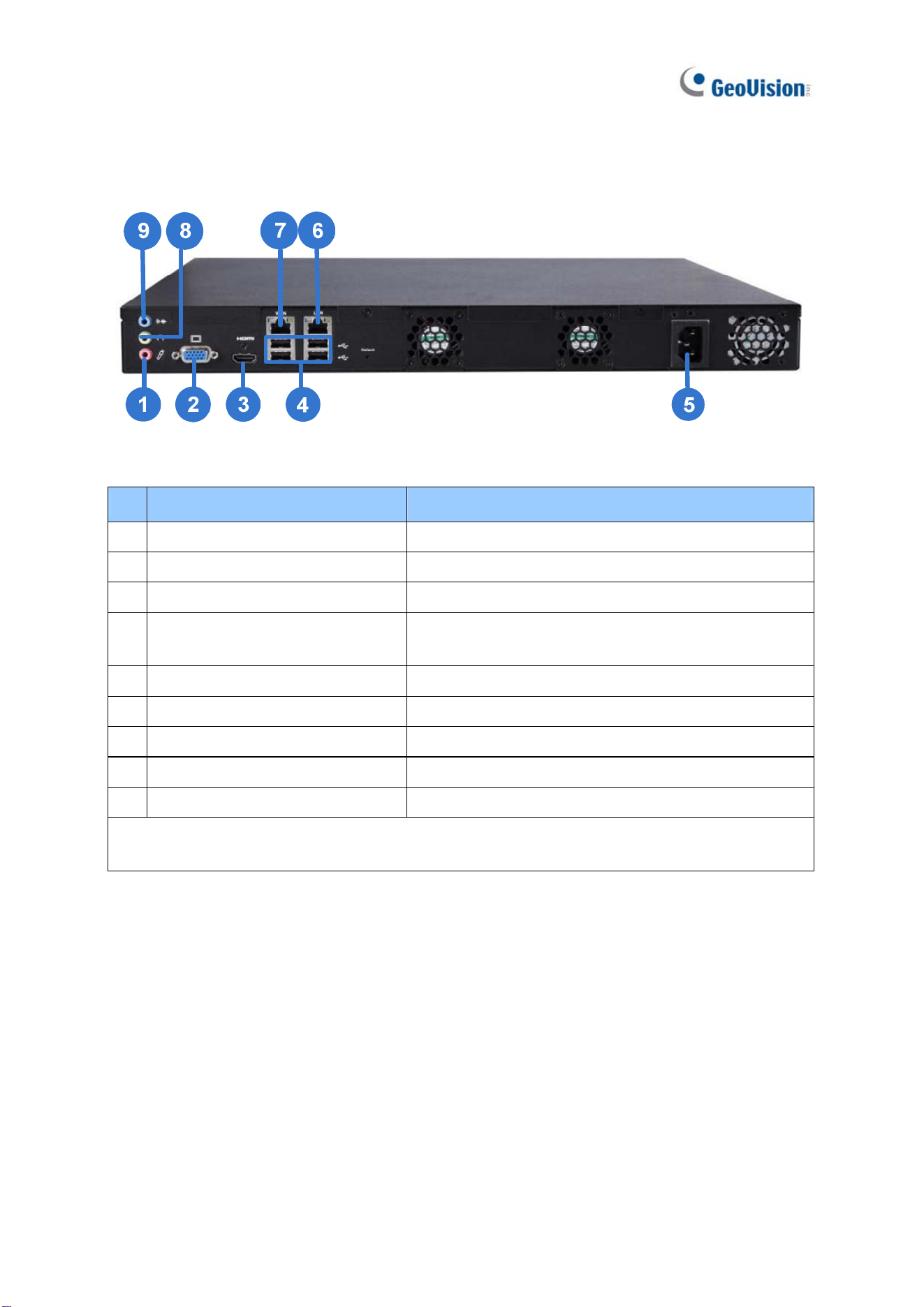
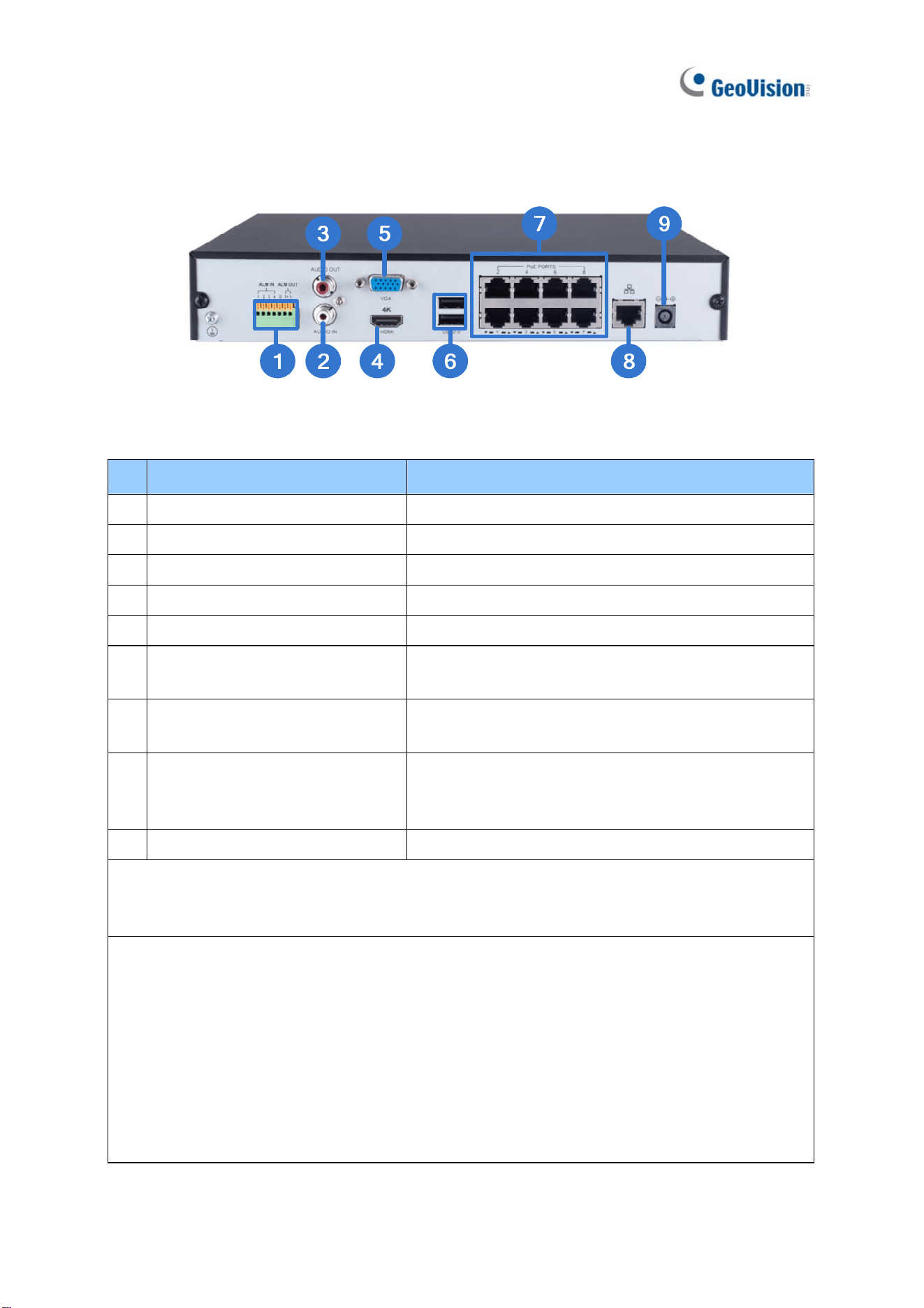
1.6.2 GV-SNVR0411 Rear View
6
1
4
2
5
3
Figure 1-3
No. Name Function
1
DC 52 V (Power Input) Connects to power supply.
2
Megabit PoE Ports
Connects to cameras, delivering power and network
connection to the cameras.
3
WAN Connects to a network.
4
USB 2.0 Port
Connects to a keyboard, mouse, USB flash drive, GV-WiFi
Adaptor V2 or GV-Joystick V2.
5 Default Button
Restores the device to its default settings. Press the button for
15 seconds to load default.
6
HDMI Output Connects to a HD TV.
IMPORTANT: Only connect GV-SNVR0411 to the Internet through its WAN Port (No. 3) as
opposed to any of the 4 PoE ports (No. 2), as they are only for connecting to IP cameras and
have limited network connection.
Introduction
16
1
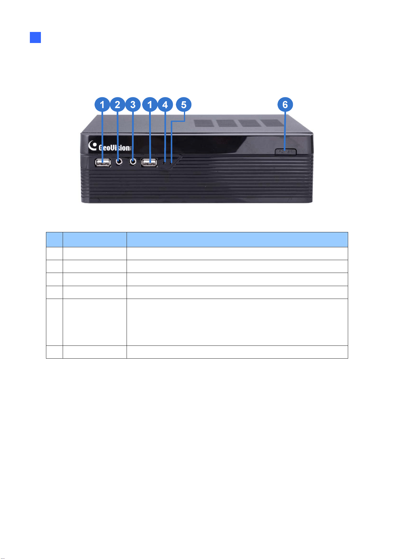
1.6.3 GV-SNVR0400F Front View
Figure 1-4
No. Name Function
1
USB 2.0 Port Connects to a keyboard, mouse, USB flash drive or GV-Joystick V2.
2
Audio In Not functional.
3
Audio Out Connects to a speaker.
4
Power LED Shows constant blue when power is supplied.
5 HDD Error LED
Shows constant red when:
˙ No hard drive is installed.
˙ The hard drive is not formatted.
˙ The hard drive fails.
6
Power Button Turns on/off the power.
17
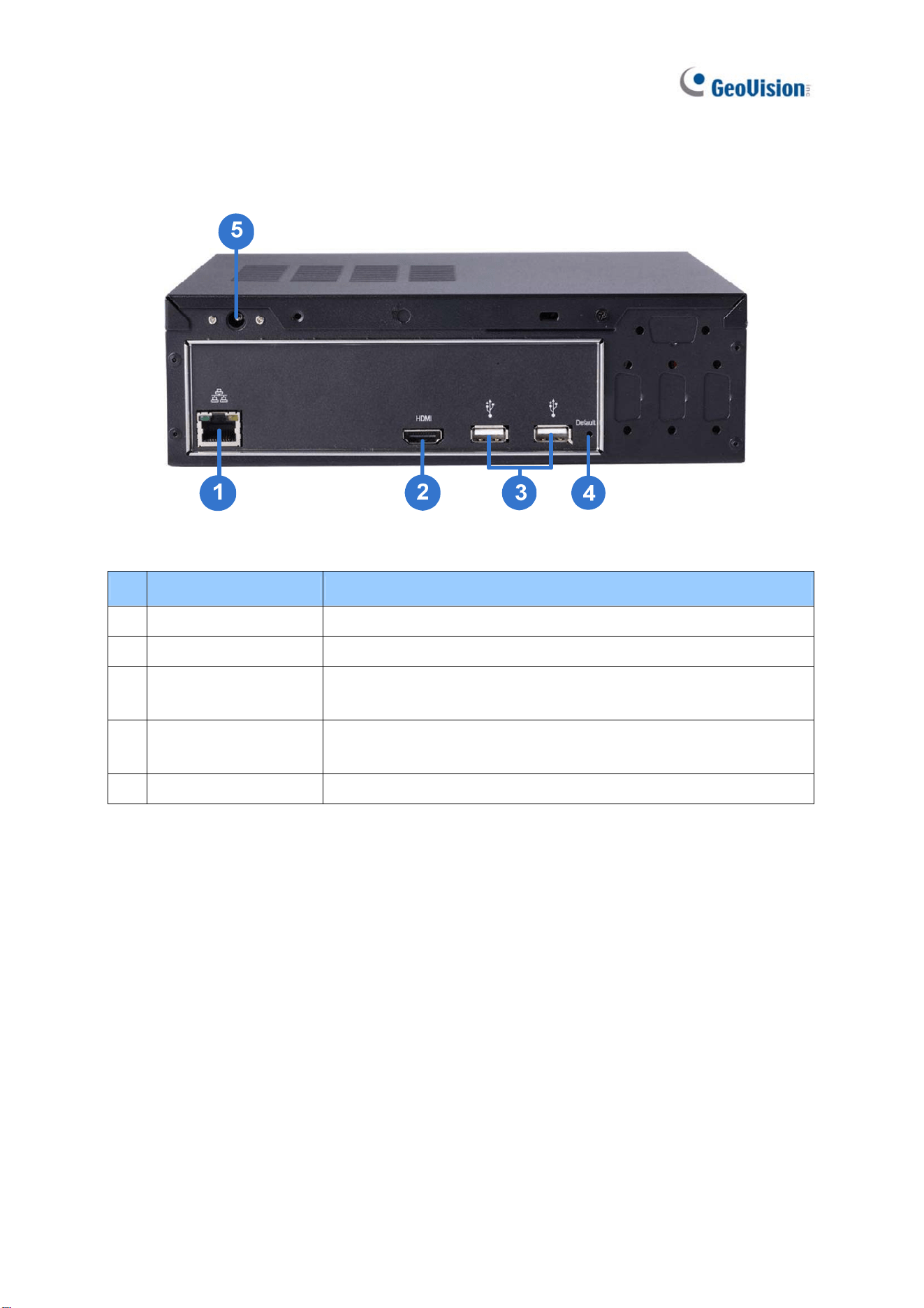
1.6.4 GV-SNVR0400F Rear View
Figure 1-5
No. Name Function
1
Gigabit Ethernet Port Connects to a network.
2
HDMI Output Connects to a HD TV.
3 USB 2.0 Port
Connects to a keyboard, mouse, USB flash drive or GV-Joystick
V2.
4
Default Button
Restores the device to default settings. Press the button for 15
seconds to load default.
5
Power Input Connects to power supply.
Introduction
18
1
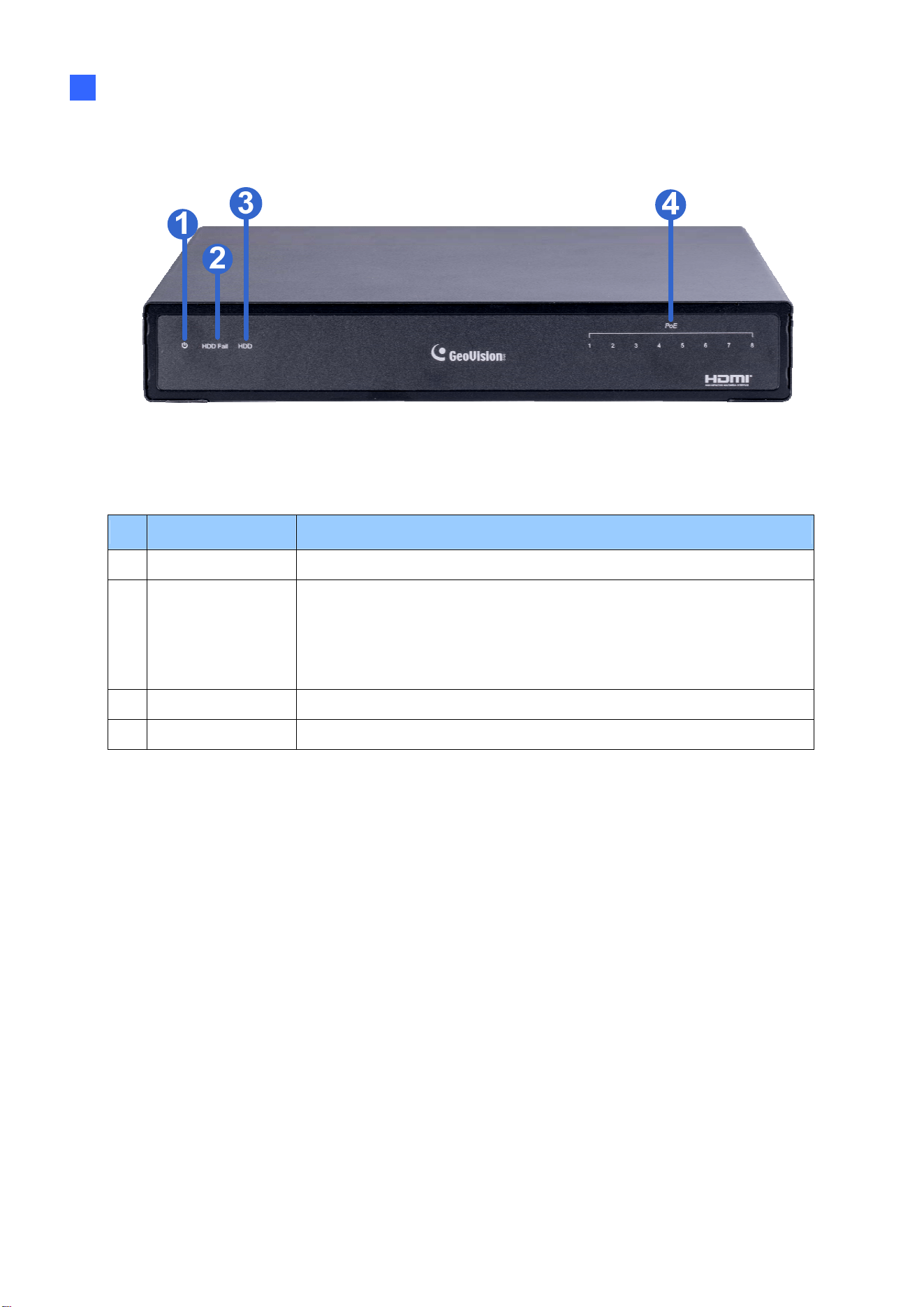
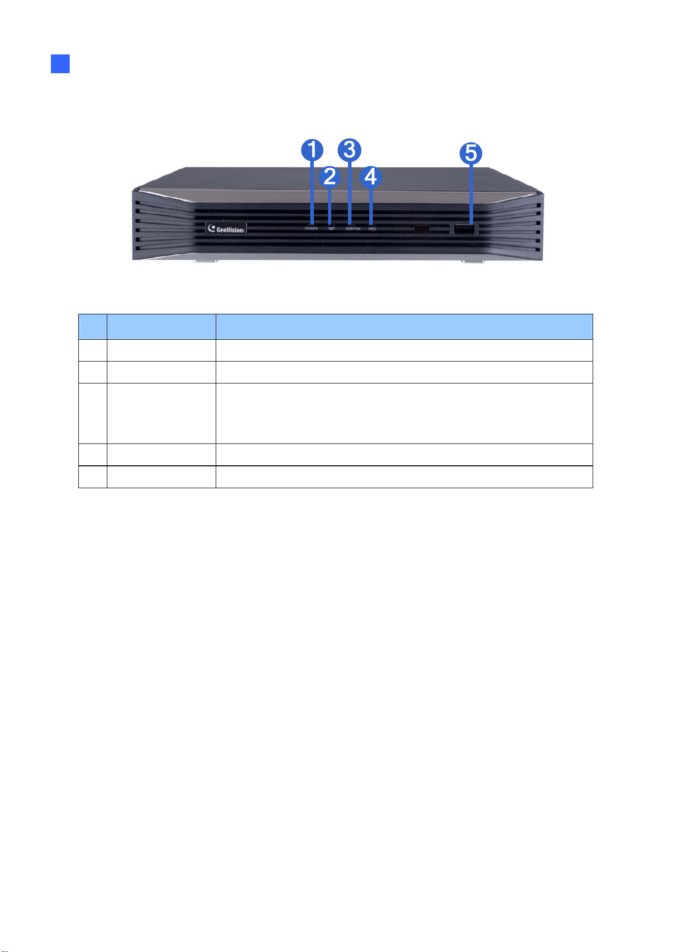
1.6.5 GV-SNVR0811 Front View
Figure 1-6
No. Name Function
1
Power LED Shows constant green when power is supplied.
2
HDD Error LED
Shows constant red when:
˙ No hard drive is installed.
˙ The hard drive is not formatted.
˙ The hard drive fails.
3
HDD LED Blinks green when the HDD is writing or reading data.
4
PoE LED Indicates the PoE port in use.
19
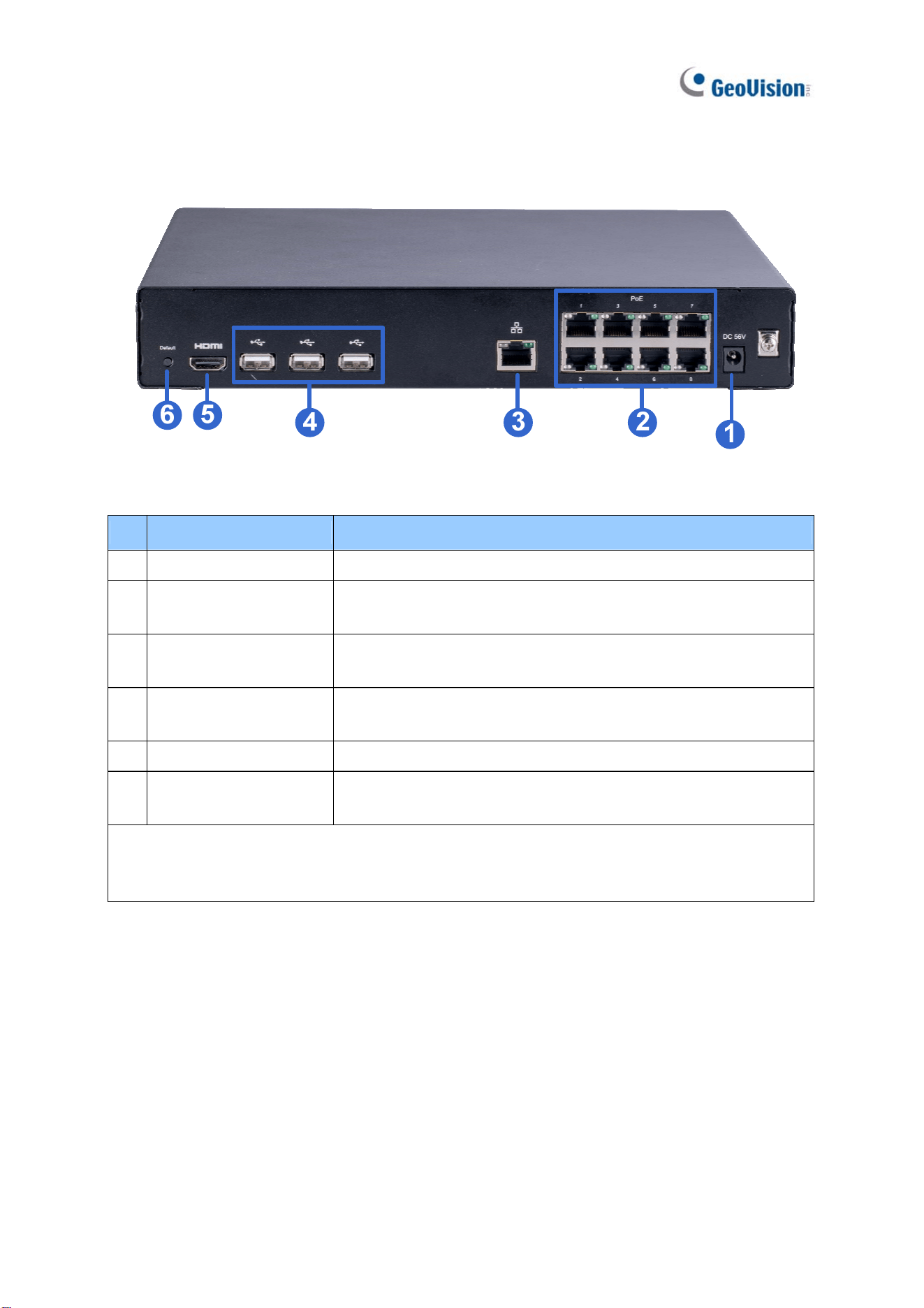
1.6.6 GV-SNVR0811 Rear View
Figure 1-7
No. Name Function
1
DC 52 V (Power Input) Connects to power supply.
2
Megabit PoE Ports
Connects to cameras, delivering power and network
connection to the cameras.
3 Network
Connects to a network. The light on the left turns orange when
connecting to Ethernet of 10 /100 Mbps.
4
USB 2.0 Port
Connects to a keyboard, mouse, USB flash drive, GV-WiFi
Adaptor V2 or GV-Joystick V2.
5
HDMI Output Connects to a HD TV.
6
Default Button
Restores the device to its default settings. Press the button for
15 seconds to load default.
IMPORTANT: Only connect GV-SNVR0811 to the Internet through its WAN Port (No. 3) as
opposed to any of the 8 PoE ports (No. 2), as they are only for connecting to IP cameras and
have limited network connection.
Introduction
20
1
1.6.7 GV-SNVR1600 Front View
1
2
3
4
5
6
7
Figure 1-8
No. Name Function
1
Power Button Turns on/off the power.
2
Power LED Shows constant blue when power is supplied.
3
HDD Status LED Flashes blue when the hard drive is writing or reading data.
4
HDD Error LED
Shows constant red when:
˙ No hard drive is installed.
˙ The hard drive is not formatted.
˙ The hard drive fails.
5
WAN LED Flashes blue when the WAN port is receiving activity.
6
LAN LED Flashes blue when the LAN port is receiving activity.
7
USB 2.0 Port Connects to a keyboard, mouse, USB flash drive or GV-Joystick V2.
1.6.1.1
21
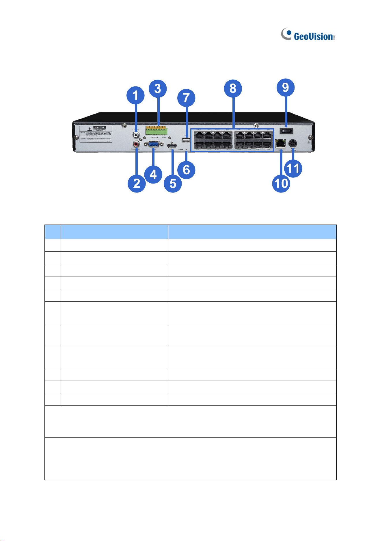
1.6.8 GV-SNVR1600 Rear View
Figure 1-9
No. Name Function
1
Audio Microphone In Port Not functional.
2
VGA Monitor Output Connects to a VGA monitor.
3
HDMI Port Connects to a HD TV.
4
USB 2.0 Port x 4
Connects to a keyboard, mouse, USB flash drive or
GV-Joystick V2.
5
Power Input Connects to power supply.
6
Gigabit Ethernet Port (LAN) Connects to a network.
7
Gigabit Ethernet Port (WAN) Connects to a network.
8
Audio Line Out Port Connects to a headphone.
9
Audio Line Out Port Connects to a speaker.
Note: When the two Ethernet ports (No. 6 and No. 7) are used together, one is LAN port and
the other is WAN port.
Introduction
22
1
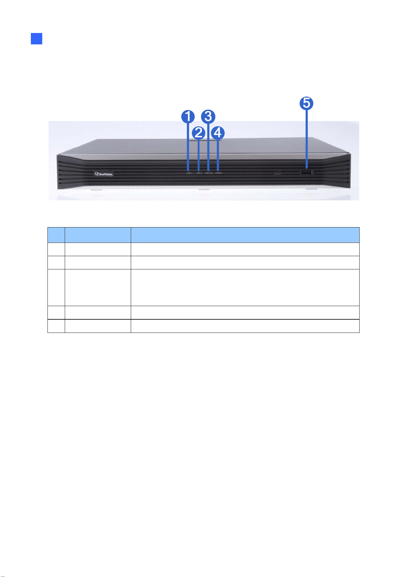
1.6.9 GV-SNVR1611 Front View
Figure 1-10
No. Name Function
1
HDD1 LED Constant blue when HDD1 is writing or reading data.
2
HDD2 LED Constant blue when HDD2 is writing or reading data.
3 HDD Fail LED
Shows constant red when one or both of the hard drives is:
˙ Not formatted.
˙ Fails to read or write.
4
Power LED Shows constant blue when power is supplied.
5
USB 2.0 Port Connects to a keyboard, mouse, USB flash drive or GV-Joystick V2.
23
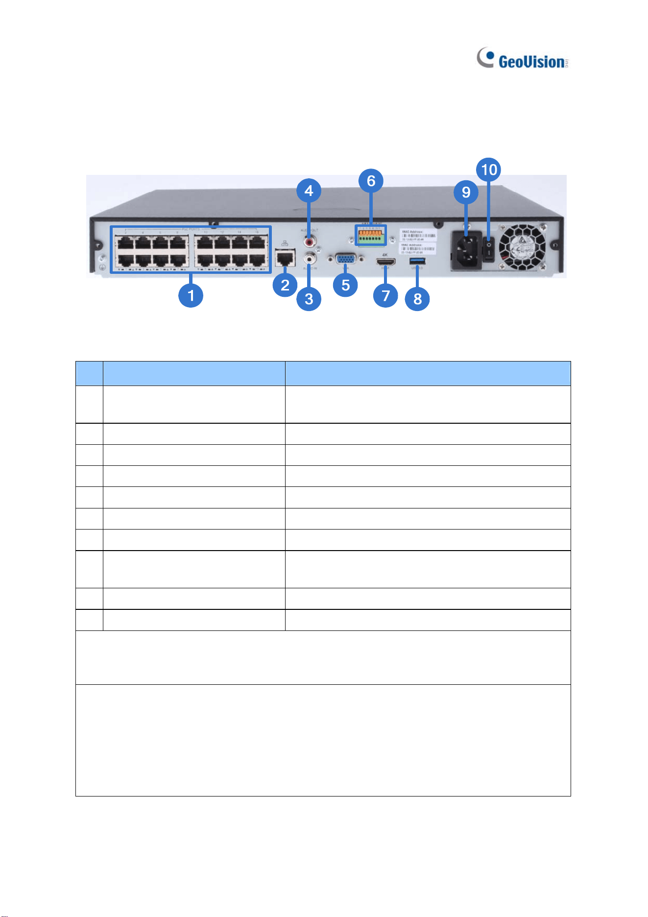
1.6.10 GV-SNVR1611 Rear View
Figure 1-11
No. Name Function
1 Megabit PoE Ports
Connects to cameras, delivering power and network
connection to the cameras.
2
Megabit Ethernet Port (WAN) Connects to a network.
3
Audio Line In Port Connects to a microphone.
4
Audio Line Out Port Connects to a speaker.
5
VGA Output Connects to a VGA monitor.
6
I/O Panel Connects to 4 input and 1 output devices
7
HDMI Output Connects to a HD TV.
8
USB 3.0 Port
Connects to a keyboard, mouse, USB flash drive or
GV-Joystick V2.
9
Power Input Connects to power supply.
10
Power Button Turns the system on or off.
IMPORTANT: Only connect GV-SNVR1611 to the Internet through its WAN Port (No. 2) as
opposed to any of the 16 PoE ports (No. 1), as they are only for connecting to IP cameras
and have limited network connection.
Note: GV-SNVR1611 does not have a load default button. To restore factory settings
manually for:
˙ Firmware V3.09 or earlier, right-click the mouse five times during the startup screen.
˙ Firmware V3.10 or later, click both the left- and right-click of the mouse 10 times within 3
seconds during the startup screen.
Or see 6.2.5 Restoring to Factory Default Settings for loading default via GV-IP Device Utility.

Introduction
24
1
1.6.11 GV-SNVR0812 Front View
Figure 1-12
No. Name Function
1
Power LED Shows constant blue when power is supplied.
2
Network LED Shows constant blue when connected to a network.
3 HDD Fail LED
Shows constant red when the hard drive is either:
˙ Not formatted.
˙ Fails to read or write.
4
HDD LED Shows constant blue when the hard drive is writing or reading data.
5
USB 2.0 Port Connects to a keyboard, mouse, USB flash drive or GV-Joystick V2.
25
1.6.12 GV-SNVR0812 Rear View
Figure 1-13
No. Name Function
1
I/O Panel Connects to 4 input and 1 output devices
2
Audio Line Out Port Connects to a speaker.
3
Audio Line In Port Connects to a microphone.
4
HDMI Output Connects to a HD TV.
5
VGA Output Connects to a VGA monitor.
6
USB 2.0 Port
Connects to a keyboard, mouse, USB flash drive or
GV-Joystick V2.
7 Megabit PoE Ports
Connects to cameras, delivering power and network
connection to the cameras.
8
Megabit Ethernet Port (WAN)
Connects to a network. The light at the bottom
flashes green when connecting to Ethernet of 10
/100 Mbps.
9
DC 52 V (Power Input) Connects to power supply.
IMPORTANT: Only connect GV-SNVR0812 to the Internet through its WAN Port (No. 8) as
opposed to any of the 8 PoE ports (No. 7), as they are only for connecting to IP cameras and
have limited network connection.
Note:
1. IP cameras connected to the PoE ports are provided network connection via an isolated
network that is not bridged to, or inaccessible by, the WAN.
2. IP cameras connected to the PoE ports are assigned a channel number in accordance to
the PoE port number.
3. GV-SNVR0812 does not have a load default button. To restore factory settings manually
for firmware V1.10 or later, click both the left- and right-click of the mouse 10 times within
3 seconds during the startup screen, or see 3.8 System or 6.2.5 Restoring to Factory
Default Settings for loading default through its UI or GV-IP Device Utility, respectively.
Introduction
26
1
1.6.13 GV-SNVR0412 Front View
Figure 1-14
No. Name Function
1
Power LED Shows constant blue when power is supplied.
2
Network LED Shows constant blue when connected to a network.
3 HDD Fail LED
Shows constant red when the hard drive is either:
˙ Not formatted.
˙ Fails to read or write.
4
HDD LED Shows constant blue when the hard drive is writing or reading data.
5
USB 2.0 Port Connects to a keyboard, mouse, USB flash drive or GV-Joystick V2.
27
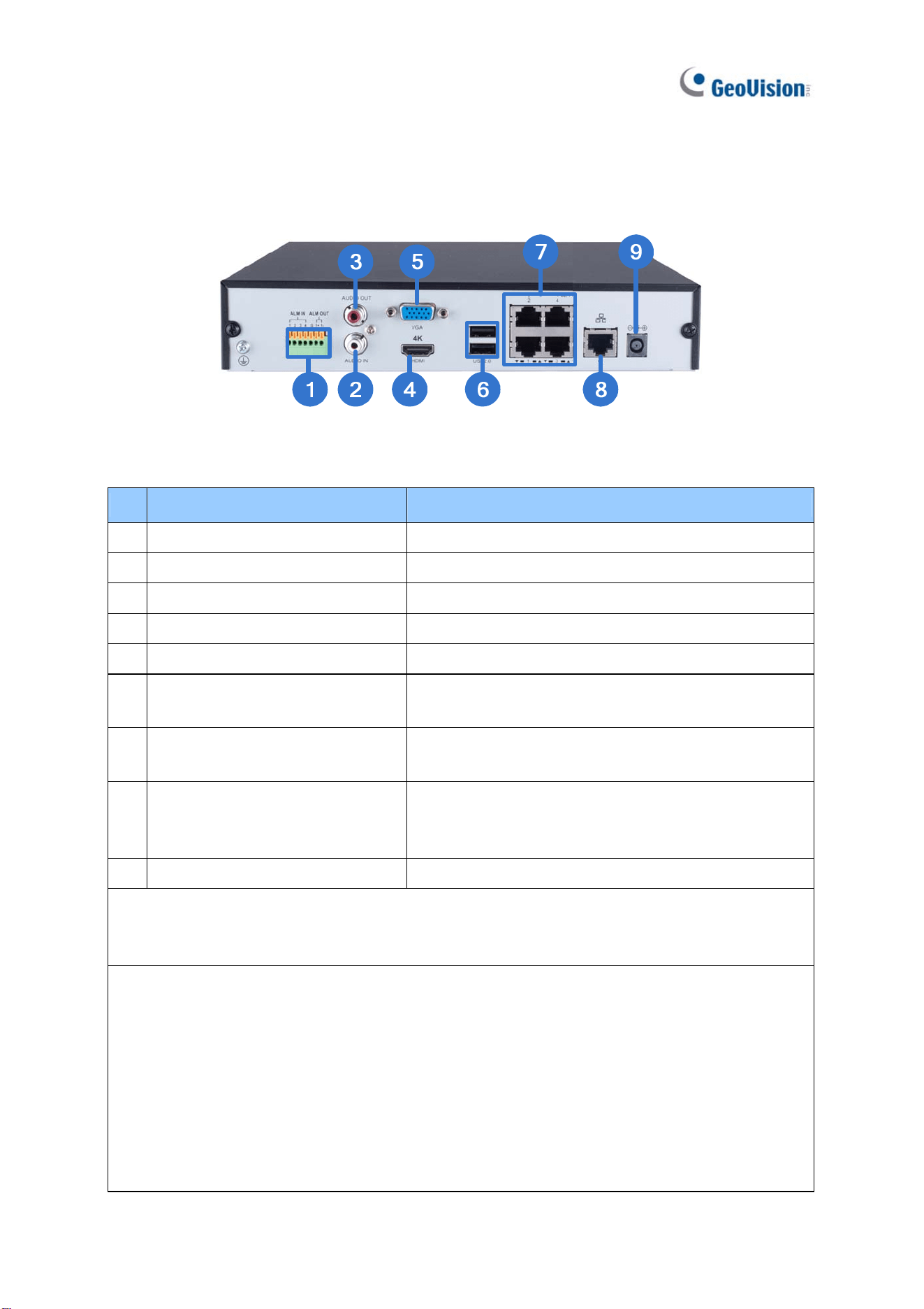
1.6.14 GV-SNVR0412 Rear View
Figure 1-15
No. Name Function
1
I/O Panel Connects to 4 input and 1 output devices
2
Audio Line Out Port Connects to a speaker.
3
Audio Line In Port Connects to a microphone.
4
HDMI Output Connects to a HD TV.
5
VGA Output Connects to a VGA monitor.
6
USB 2.0 Port
Connects to a keyboard, mouse, USB flash drive or
GV-Joystick V2.
7 Megabit PoE Ports
Connects to cameras, delivering power and network
connection to the cameras.
8
Megabit Ethernet Port (WAN)
Connects to a network. The light at the bottom
flashes green when connecting to Ethernet of 10
/100 Mbps.
9
DC 52 V (Power Input) Connects to power supply.
IMPORTANT: Only connect GV-SNVR0412 to the Internet through its WAN Port (No. 8) as
opposed to any of the 4 PoE ports (No. 7), as they are only for connecting to IP cameras and
have limited network connection.
Note:
1. IP cameras connected to the PoE ports are provided network connection via an isolated
network that is not bridged to, or inaccessible by, the WAN.
2. IP cameras connected to the PoE ports are assigned a channel number in accordance to
the PoE port number.
3. GV-SNVR0412 does not have a load default button. To restore factory settings manually
for firmware V1.05 or later, click both the left- and right-click of the mouse 10 times within
3 seconds during the startup screen, or see 3.8 System or 6.2.5 Restoring to Factory
Default Settings for loading default through its UI or GV-IP Device Utility, respectively.
Introduction
28
1
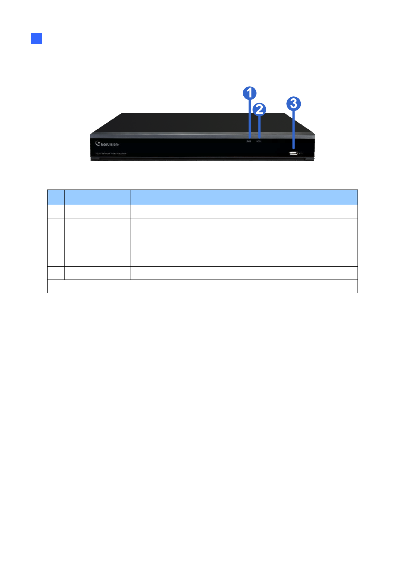
1.6.15 GV-SNVR1612 Front View
Figure 1-16
No. Name Function
1
Power LED Shows constant blue when power is supplied.
2
HDD Fail LED
Shows constant red when:
˙ No hard drive is installed.
˙ The hard drive is not formatted.
˙ The hard drive fails.
3
USB 2.0 Port Connects to a keyboard, mouse, USB flash drive or GV-Joystick V2.
Note: An e-mail alert will be sent when the HDD(s) fails.
29
1.6.16 GV-SNVR1612 Rear View
Figure 1-17
No. Name Function
1
Audio Line In Port Connects to a microphone.
2
Audio Line Out Port Connects to a speaker.
3
I/O Panel
Connects to 8 input and 1 output devices
4
VGA Output
Connects to a VGA monitor.
5
HDMI Output Connects to a HD TV.
6
Default Button
Restores the device to default settings. Press the
button for 15 seconds to load default.
7 USB 2.0 Port
Connects to a keyboard, mouse, USB flash drive or
GV-Joystick V2.
8
Megabit PoE Ports
Connects to cameras, delivering power and network
connection to the cameras.
9
Power Button Turns the system on or off.
10
Megabit Ethernet Port (WAN) Connects to a network.
11
Power Input Connects to power supply.
IMPORTANT: Only connect GV-SNVR1612 to the Internet through its WAN Port (No. 10) as
opposed to any of the 16 PoE ports (No. 8), as they are only for connecting to IP cameras
and have limited network connection.
Note: GV-SNVR1612 does not have a load default button. To restore factory settings
manually, click both the left- and right-click of the mouse 10 times within 3 seconds during the
startup screen.
Or see 6.2.5 Restoring to Factory Default Settings for loading default via GV-IP Device Utility.
30
Chapter 2 Getting Started
2.1 Installation
GV-SNVR uses SATA hard drive(s) for video data storage. Before recording, be sure to install
the hard drive.
2.1.1 GV-SNVR0411
Installing the Hard Drive
Follow the steps below to install the hard drive to GV-SNVR0411.
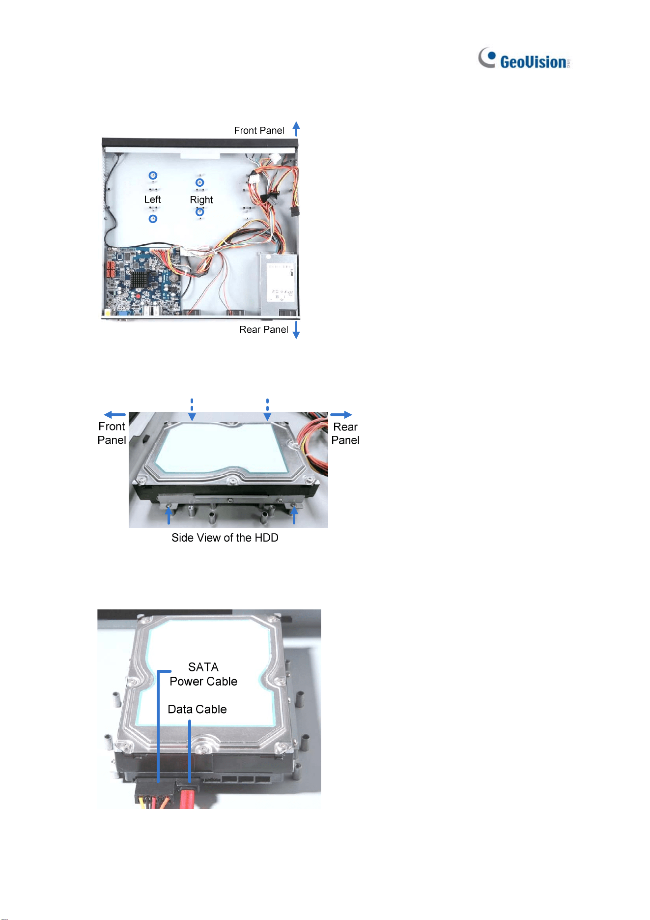
1. Unscrew three screws on the bottom and two screws on the sides; then remove the
cover.
Figure 2-1
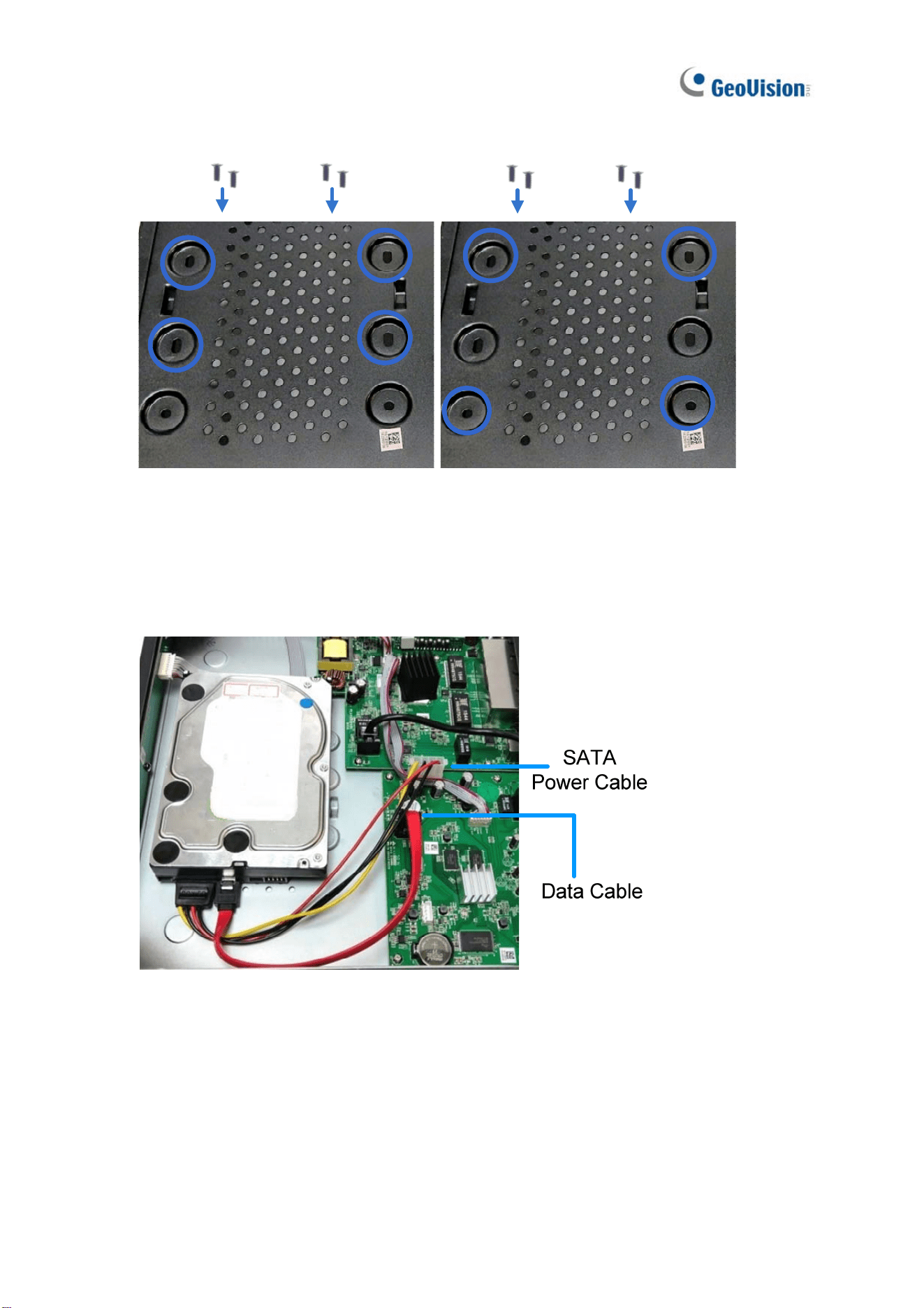
2. Place the supplied rubber foots on four of the six oval holes and place the hard drive in
the drive drawer as below by aligning the four holes.
Figure 2-2 Figure 2-3
31
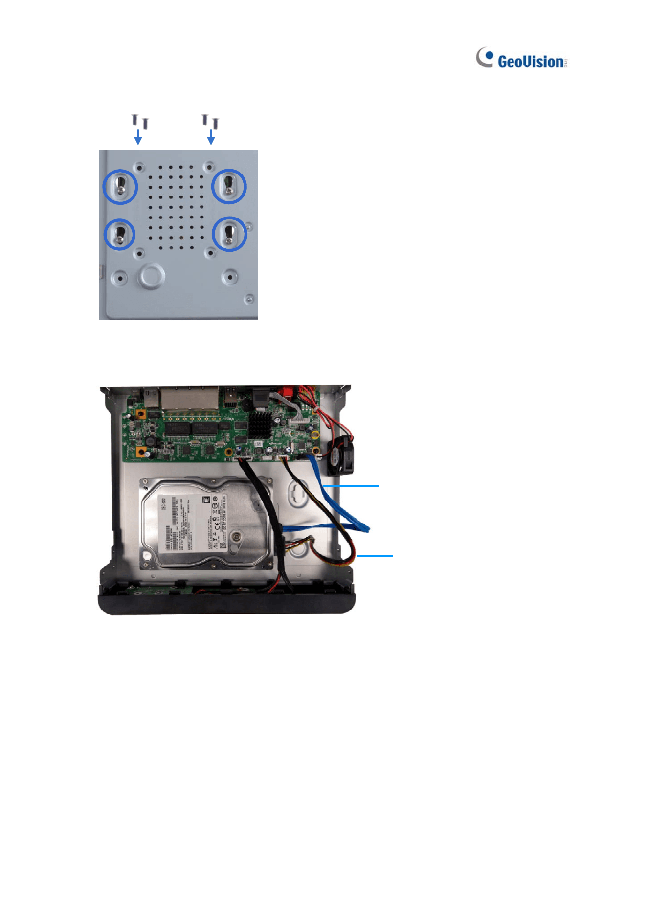
3. Secure the hard drive from the back of the drawer using the 4 supplied screws.
Figure 2-4
4. Connect the SATA Power Cable and Data Cable to the hard drive.
SATA
Power Cable
Data Cable
Figure 2-5
5. Assemble the cover with the device by tightening the screws on the bottom and sides.
(Figure 2-1).
The hard drive is now ready for use.
Getting Started
32
2
2.1.2 GV-SNVR0811
Installing the Hard Drive
Follow the steps below to install the hard drive to GV-SNVR0811.
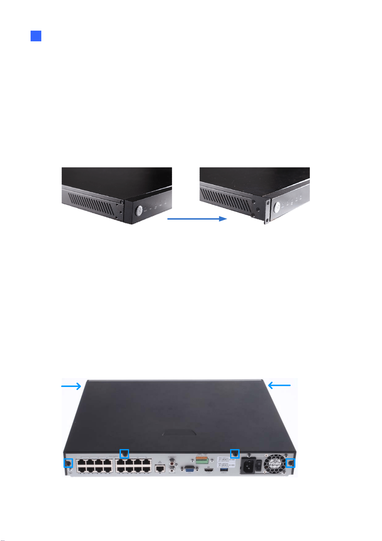
1. Unscrew the two screws on both sides and remove the cover.
Figure 2-6
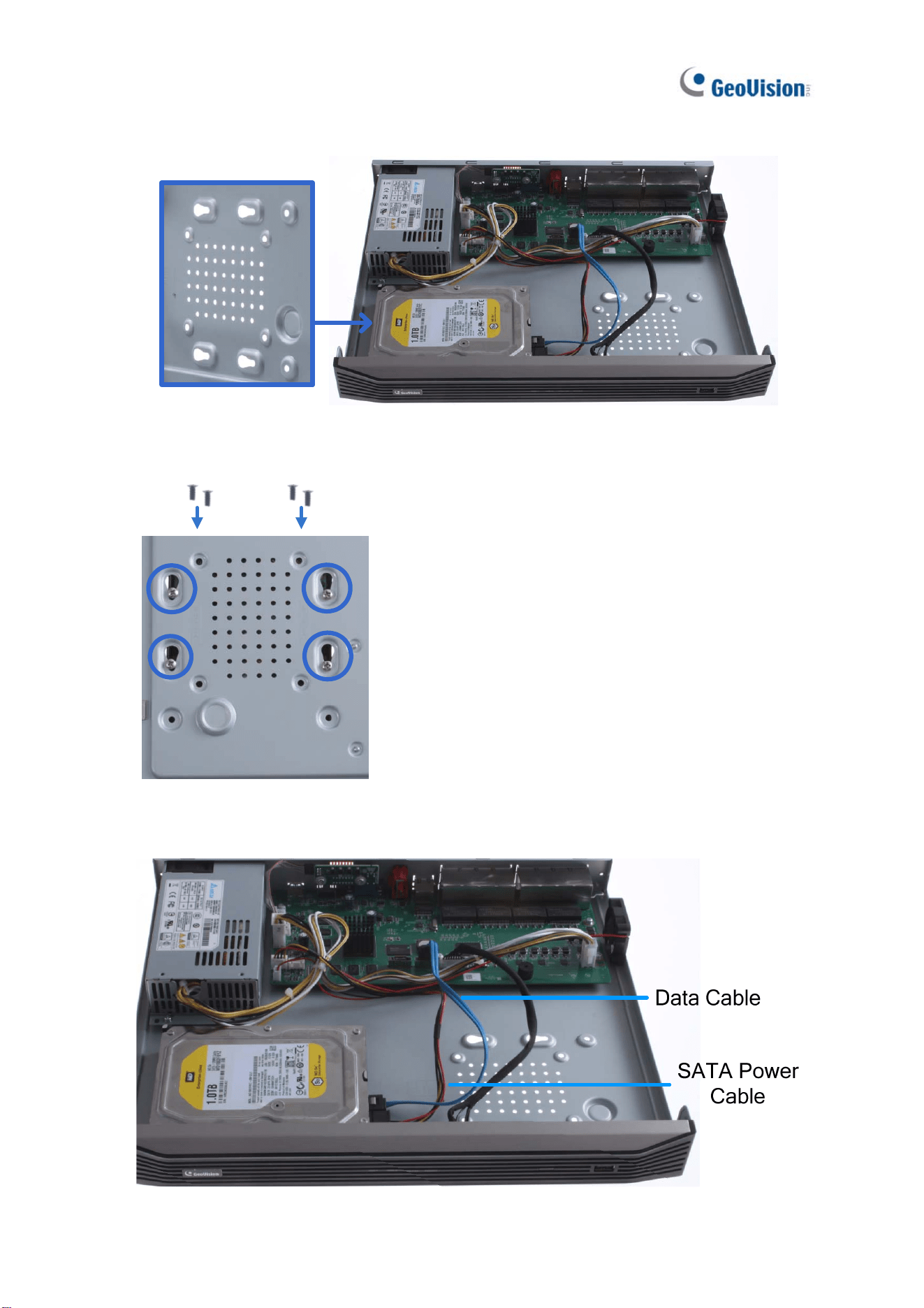
2. Place the hard drive in the driver drawer.
Figure 2-7
33
3. Secure the hard drive from the back of the drawer using the 4 supplied screws.
For hard drive under 4 TB For hard drive above 4 TB
Figure 2-8
4. Connect the SATA Power Cable and Data Cable to the hard drive.
Figure 2-9
5. Assemble the cover with the device by tightening the screws on both sides.
The hard drive is now ready for use.
Getting Started
34
2
2.1.3 GV-SNVR0400F
Installing the Hard Drive
Follow the steps below to install the hard drive to GV-SNVR0400F.
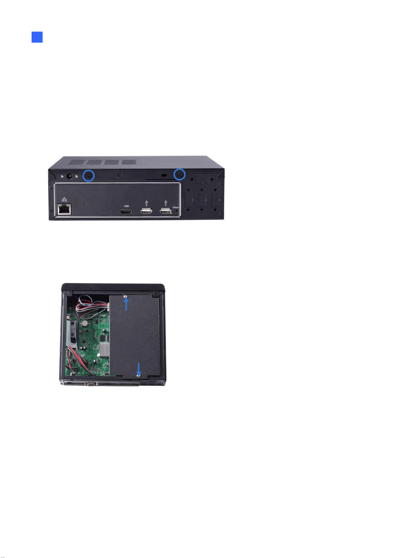
1. Unscrew the two screws on the rear panel and remove the cover.
Figure 2-10
2. Unscrew the drive drawer and take it out from the device.
Figure 2-11
35
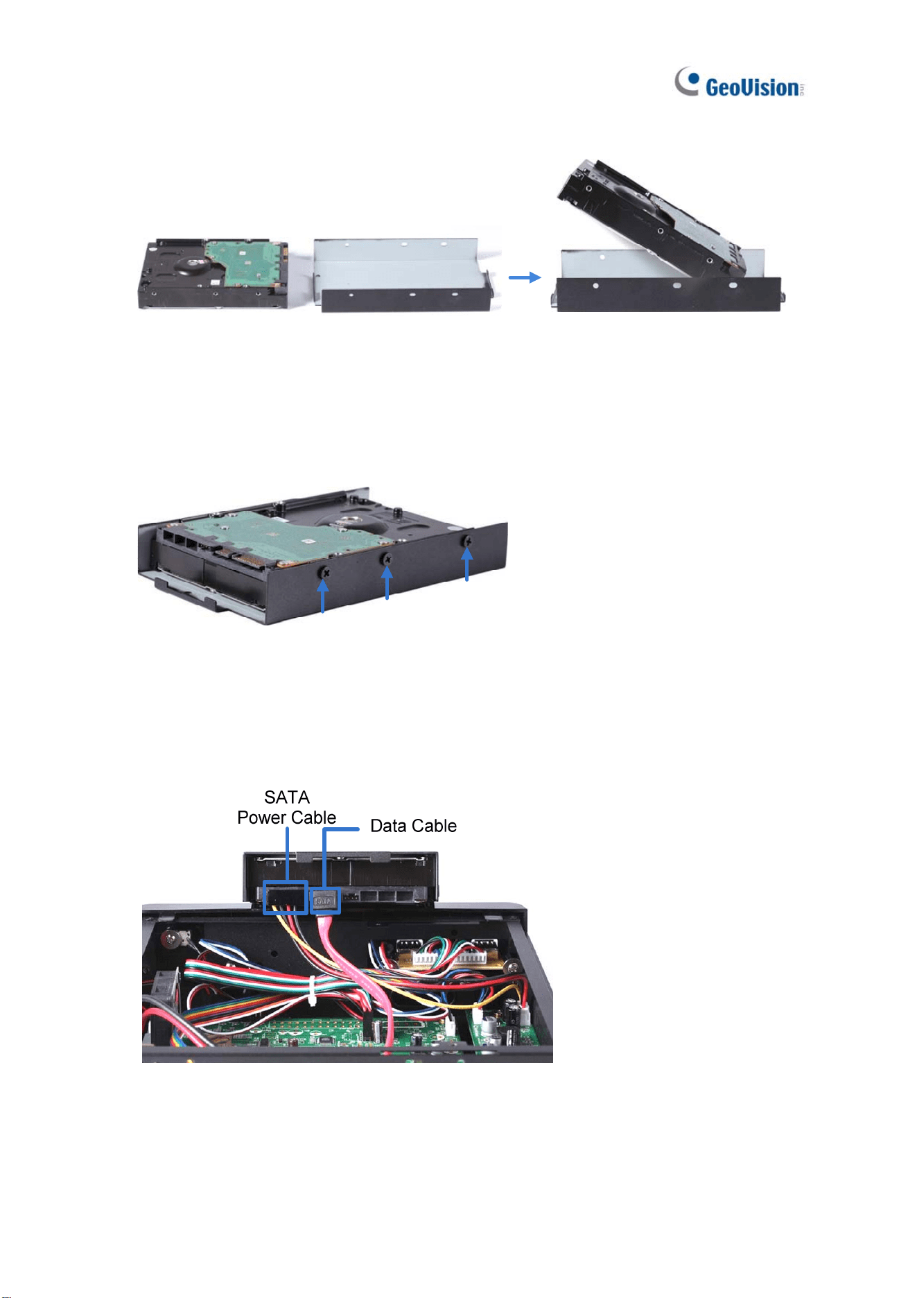
3. Place the hard drive in the drive drawer as below by aligning the three holes.
Figure 2-12
4. Secure the hard drive with the drive drawer using the 6 supplied screws (3 screws on
each side).
Figure 2-13
5. Connect the SATA Power Cable and Data Cable to the hard drive.
Figure 2-14
Getting Started
36
2
6. Put the drive drawer back in the device and secure the two screws on the drive drawer
(Figure 2-11).
7. Assemble the cover with the device by tightening the screws on rear panel (Figure 2-10).
The hard drive is now ready for use.
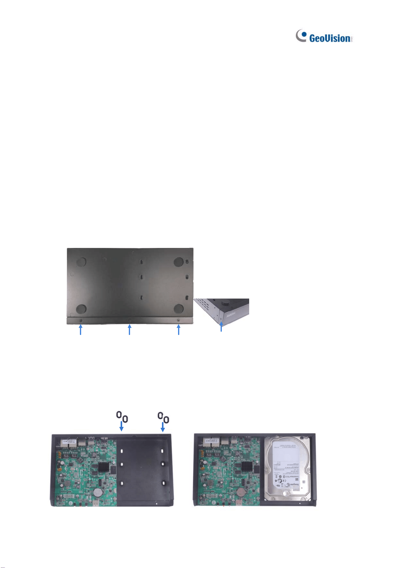
2.1.4 GV-SNVR1600
Installing the Hard Drive
Follow the steps below to install the hard drive to GV-SNVR1600.
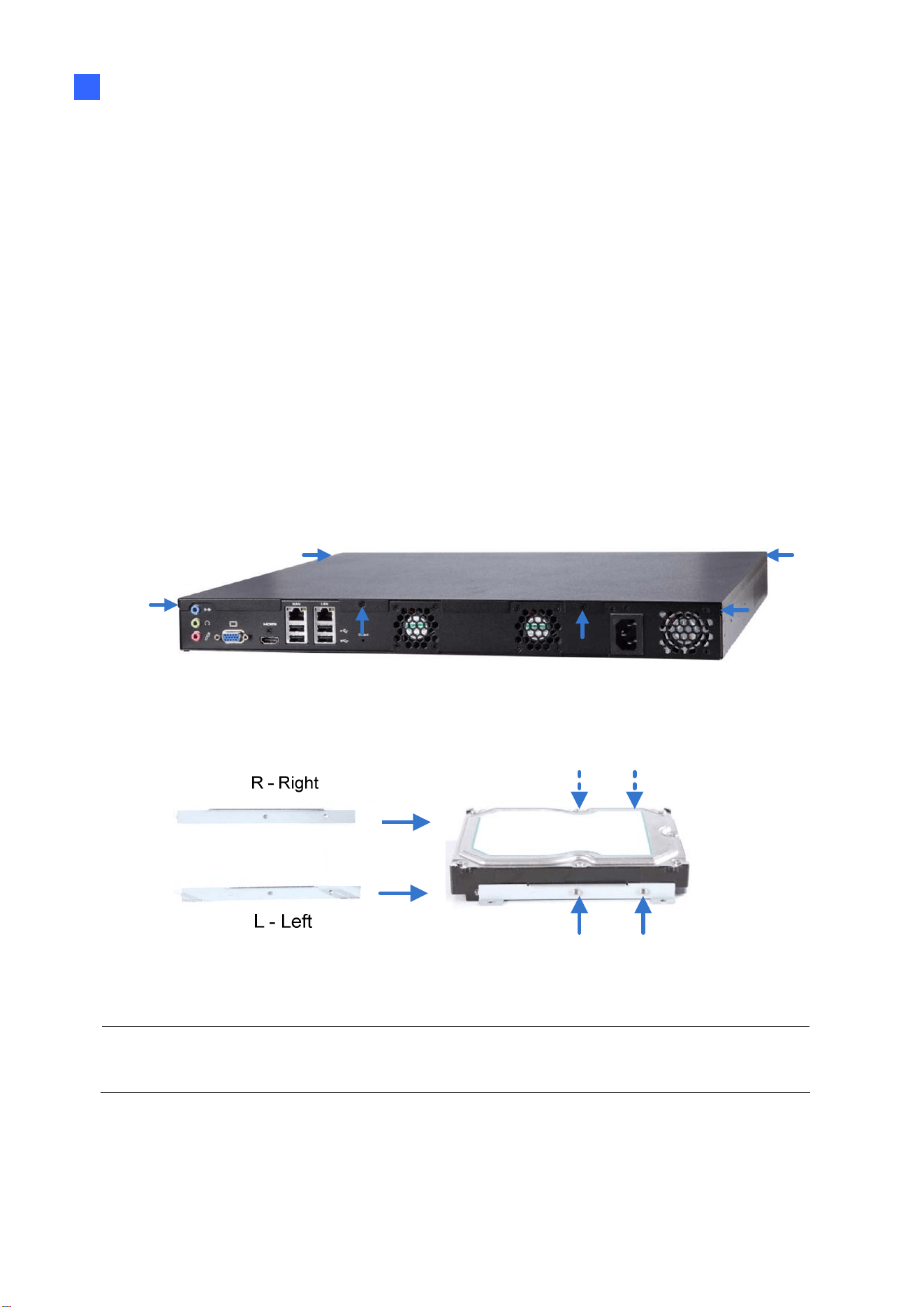
1. Loosen the 6 screws and remove the cover.
Figure 2-15
2. Assemble the mounting brackets with the hard drive and tighten the screws on both sides.
Figure 2-16
Note: Each mounting bracket is labeled L or R for recognition. Align the mounting bracket
with the holes on the hard drive and make sure it is secured to the correct side.
37
3. Align the mounting bracket with the holes inside the unit.
Figure 2-17
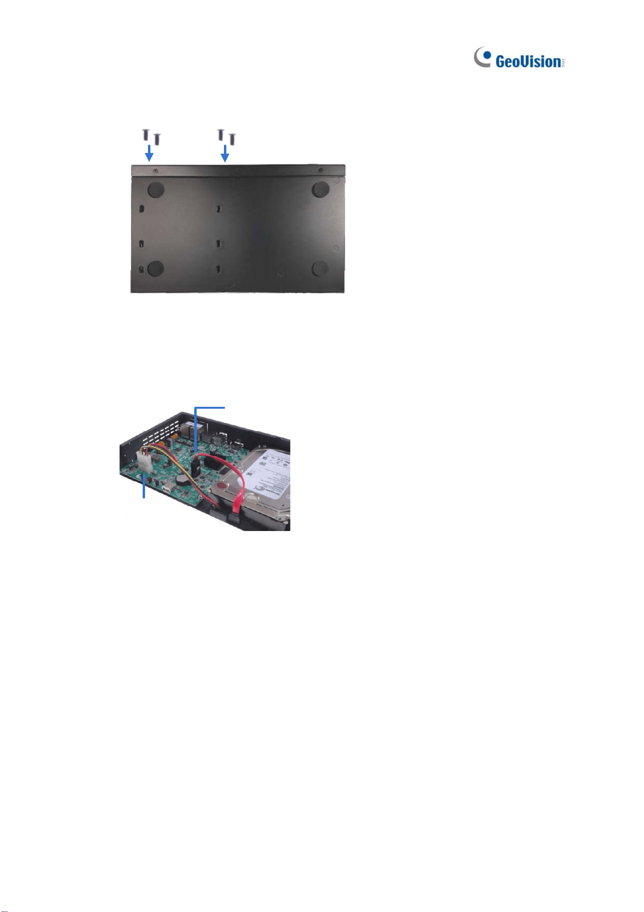
4. Tighten the 4 screws on the side of the hard drive.
Figure 2-18
5. Connect the SATA Power Cable and Data Cable to the hard drive.
Figure 2-19
Getting Started
38
2
6. To install more HDDs, repeat the steps above.
7. Place the cover back and tighten the screws.
The hard drive is now ready for use.
Installing the L-Shaped Brackets
Tighten the 6 screws to secure and attach the 2 L-shaped brackets to each side of
GV-SNVR1600.
Figure 2-20
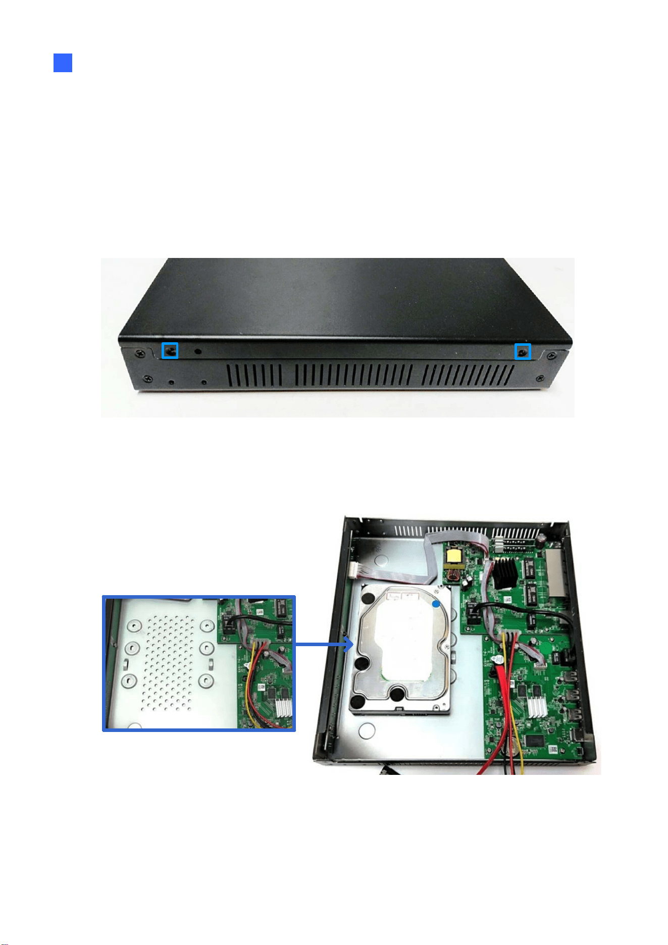
2.1.5 GV-SNVR1611 / 1612
Installing the Hard Drive
Follow the steps below to install the hard drive to GV-SNVR1611 / 1612.
1. Unscrew the two screws on both sides and the four screws on the rear to remove the
cover.
Figure 2-21
39
2. Place the hard drive in the driver drawer.
Figure 2-22
3. Secure the hard drive from the back of the drawer using the 4 supplied screws.
Figure 2-23
4. Connect the SATA Power Cable and Data Cable to the hard drive.
Figure 2-24
Getting Started
40
2
5. Assemble the cover with the device by tightening the screws on both sides and the rear
side.
The hard drive is now ready for use.
2.1.6 GV-SNVR0412 / 0812
Installing the Hard Drive
Follow the steps below to install the hard drive to GV-SNVR0412 / 0812.
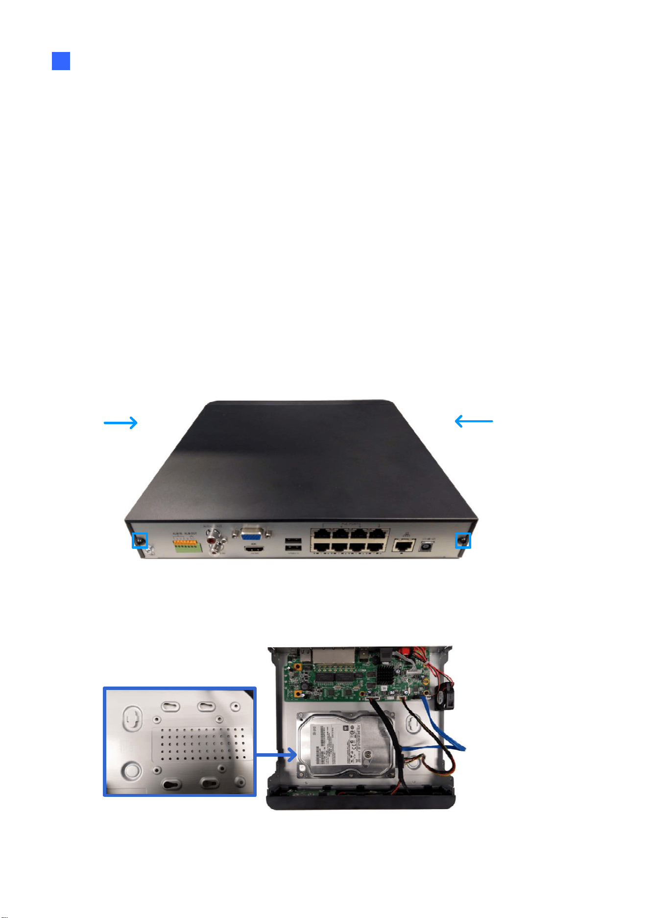
1. Unscrew the two screws on both sides and the two screws on the rear to remove the
cover.
Figure 2-25
2. Place the hard drive in the driver drawer.
Figure 2-26
41
3. Secure the hard drive from the back of the drawer using the 4 supplied screws.
Figure 2-27
4. Connect the SATA Power Cable and Data Cable to the hard drive.
SATA Power
Cable
Data Cable
Figure 2-28
5. Assemble the cover with the device by tightening the screws on both sides and the rear
side.
The hard drive is now ready for use.
Getting Started
42
2
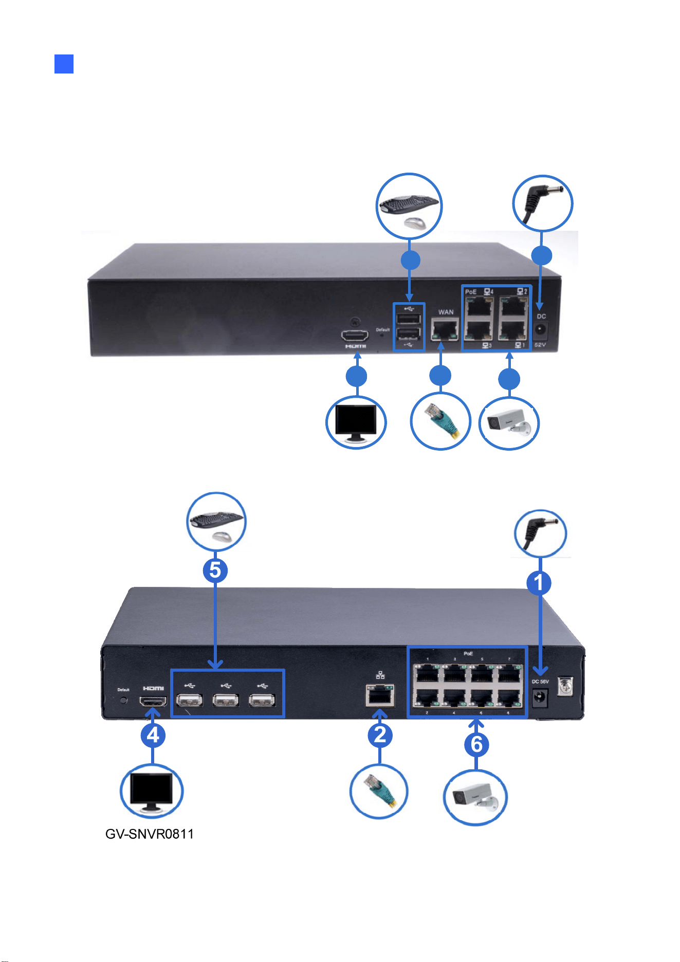
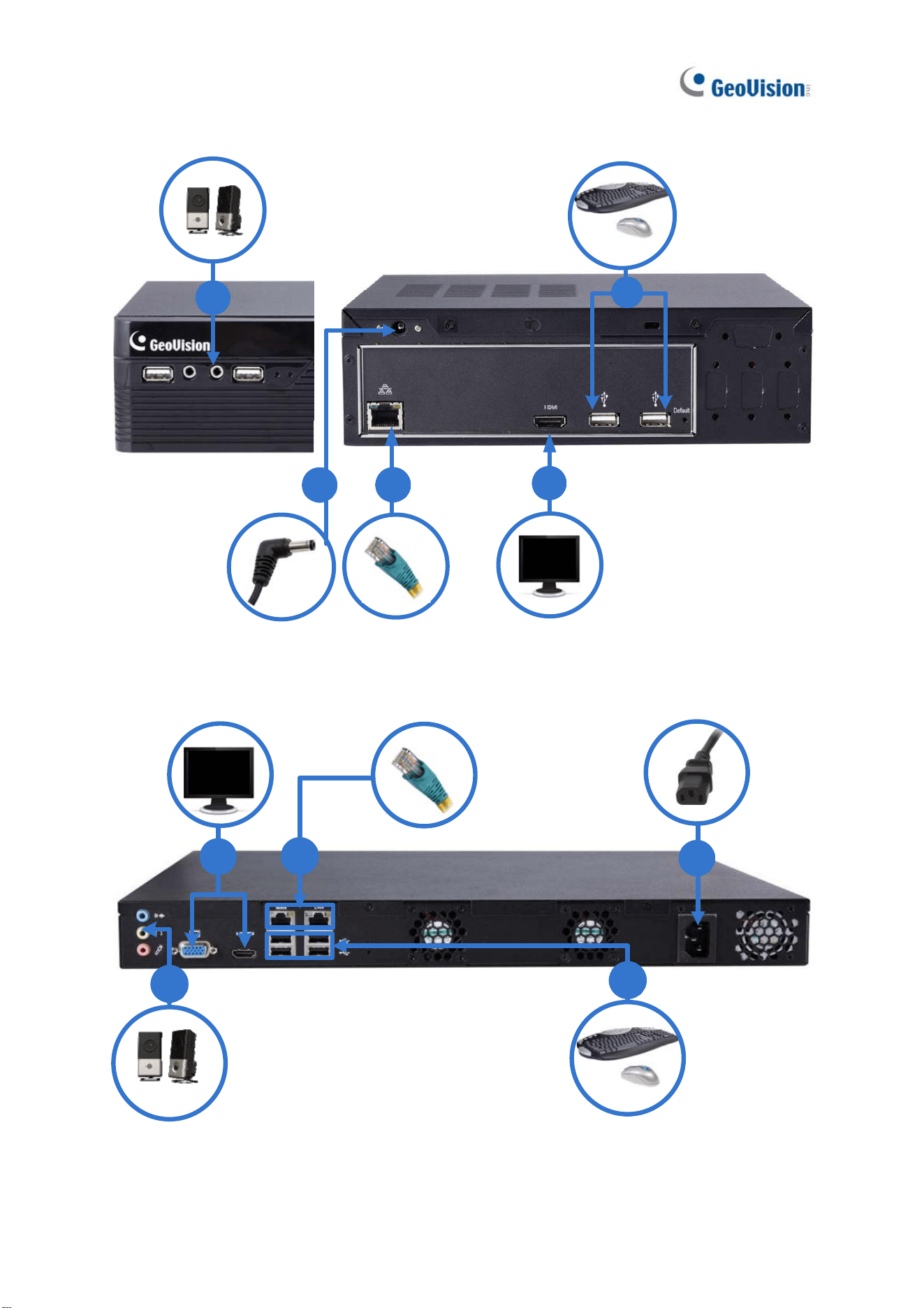
2.2 Connecting GV-SNVR
Follow the steps below to connect GV-SNVR.
GV-SNVR0411
4
6
1
2
5
43
GV-SNVR0400F
4
2
1
3
5
GV-SNVR1600
2
1
4
3
5
Getting Started
44
2
1
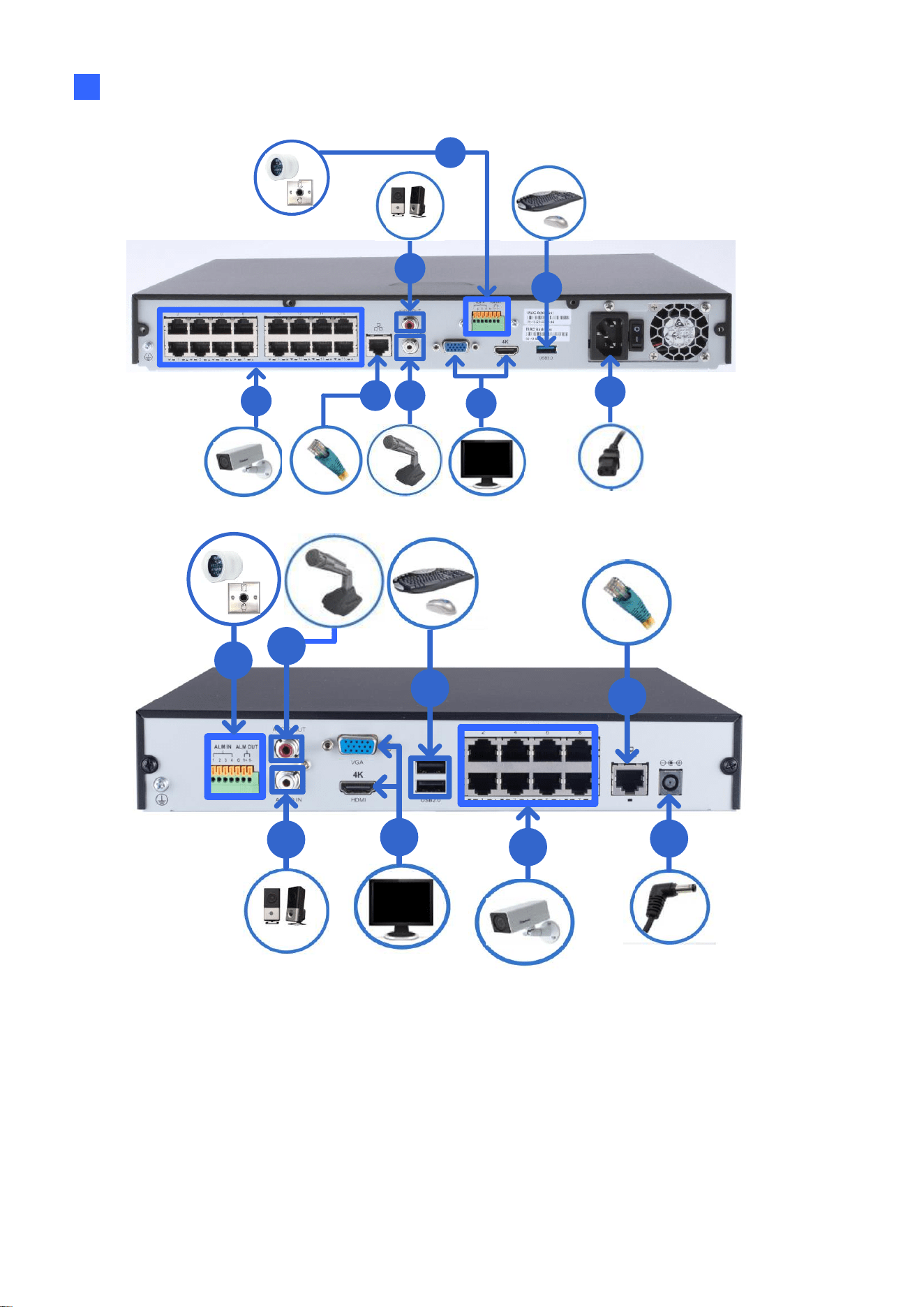
GV-SNVR1611
4
6
5
3-1
7
2
3-2
GV-SNVR0412
/ 0812
6
5
7
1
2
3-1
4
3-2
45
1
2
GV-SNVR1612
4
6
5
3-1
7
3-2
Figure 2-29
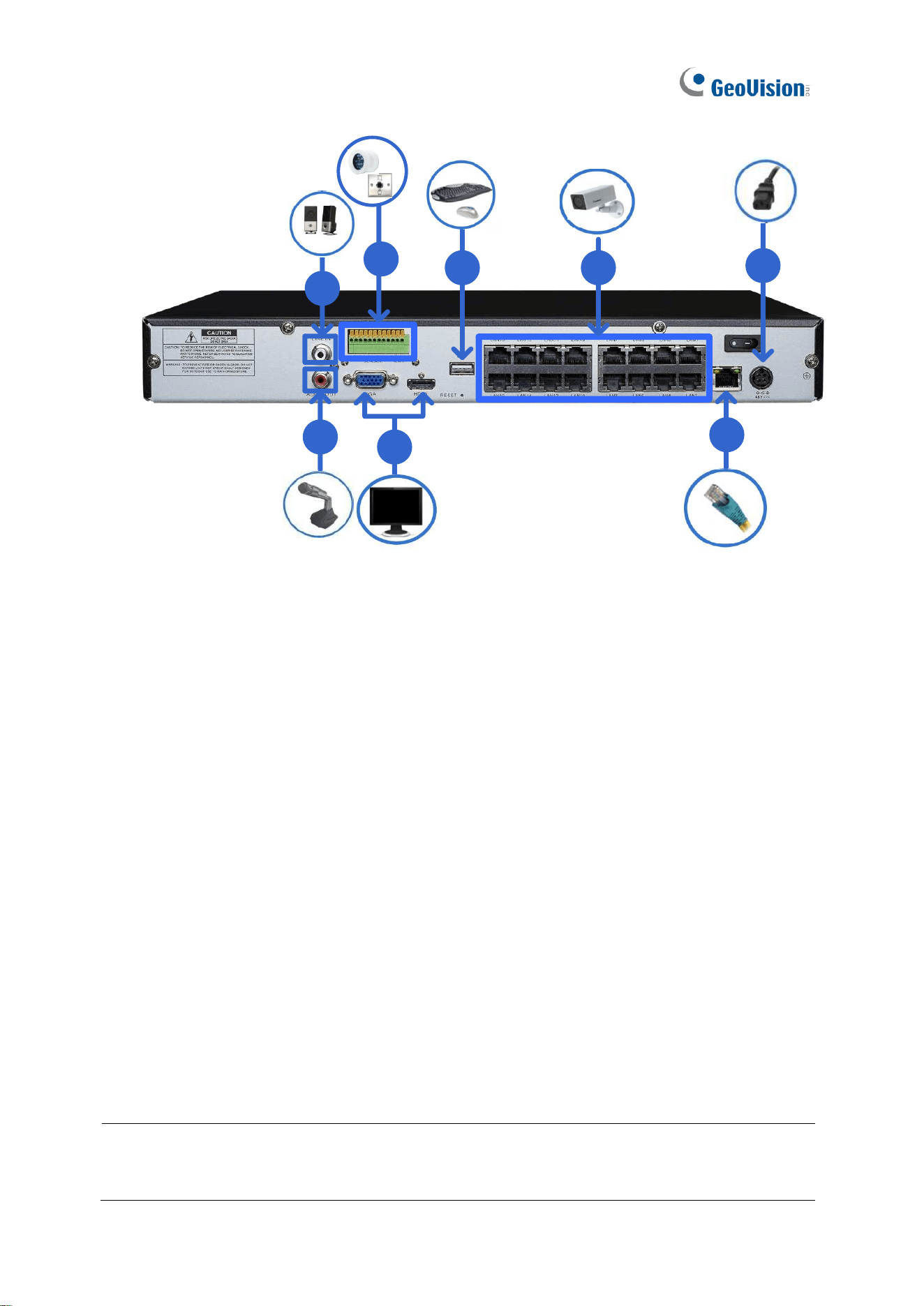
1. Connect GV-SNVR to power.
2. Connect GV-SNVR to a network using the Ethernet cable. For GV-SNVR0411 / 0412 /
0811 / 0812 / 1611 / 1612, only connect to a network via its specified LAN / WAN port as
illustrated.
3-1 Connect a speaker to the Audio Line Out port.
3-2 Connect a microphone to the Audio Line In port.
4 Connect an HDTV to HDMI connector for video/audio output. Only for GV-SNVR0412 /
0812 / 1600 / 1611 1612, optionally connect a VGA monitor to the D-Sub connector for
dual-monitor display.
5 Connect a mouse and/or keyboard to the USB port(s).
6 Only for GV-SNVR0411 / 0412 / 0811 / 0812 / 1611 / 1612, connect cameras to
GV-SNVR using Ethernet cables.
7 Only for GV-SNVR0412 / 0812 / 1611 / 1612, optionally connect input / output devices to
GV-SNVR.
Press or switch on the power button to start GV-SNVR.
IMPORTANT: For all models except GV-SNVR0400F / 1600, only connect GV-SNVR to the
Internet through its WAN Port as opposed to any of the PoE ports, as they are only for
connecting to IP cameras and have limited network connection.

Getting Started
46
2
Note:
1. GV-SNVR is DHCP enabled. When it is connected to a network, it will be automatically
assinged an IP address.
2. For GV-SNVR1600, the monitor used for VGA output must be capable of having a
screen resolution of 1080p. For GV-SNVR0411 / 0412 / 0811 / 0812 / 1611 / 1612, when
configuring the camera’s video resolution to 4K, make sure your monitor is a 4K-capable
monitor.
3. It is recommended to use HDMI-certified cables. Be aware that signal instabilities may
occur if the HDMI cable used exceeds a legnth of 10 m.
47
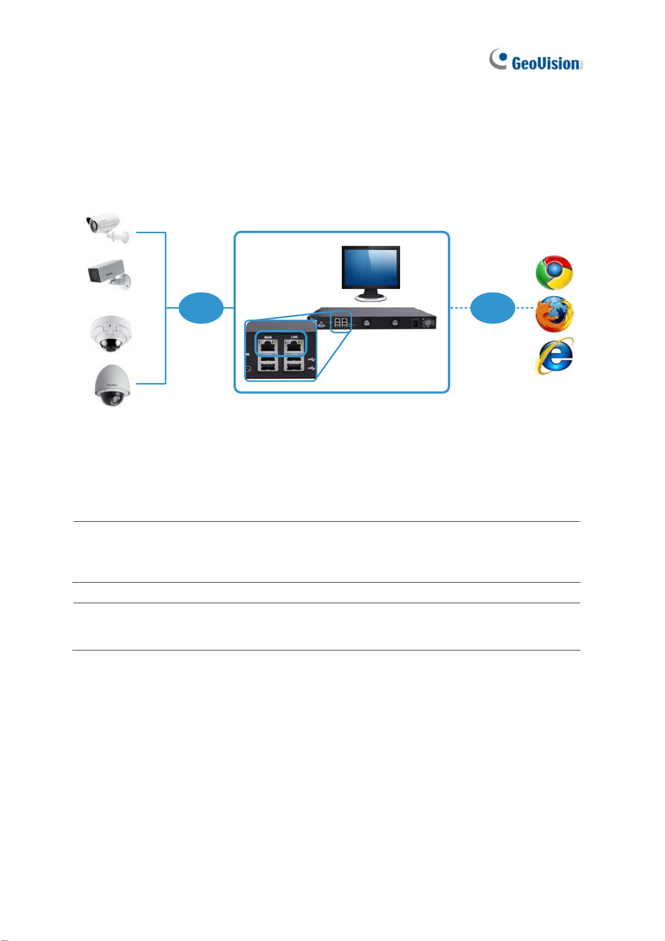
2.2.1 Network Connection for GV-SNVR1600
There are two network ports, LAN and WAN, for GV-SNVR1600. If both network ports are
used simultaneously, only the WAN port can be connected to the Internet. Therefore, it is
recommended to connect the devices as below.
GV-SNVR1600
Internet
LAN
GV-IP Cameras
WAN
Figure 2-30
1. Connect GV-IP Cameras to GV-SNVR1600 through the LAN port.
2. Connect GV-SNVR1600 to the Internet through the WAN port.
Note: When the LAN and WAN ports are used together, the Auto Search function is only
supported by the LAN port. To connect to GV-IP Cameras under the WAN, you can add the
cameras manually.
IMPORTANT: It is required to divide LAN and WAN networks into different subnets or
segments; otherwise, your network will fail. For details, see 3.3 Network.
Getting Started
48
2
2.2.2 Accessing GV-SNVR
This function is only for GV-SNVR0411 / 0412 / 0811 / 0812 / 1611 / 1612.
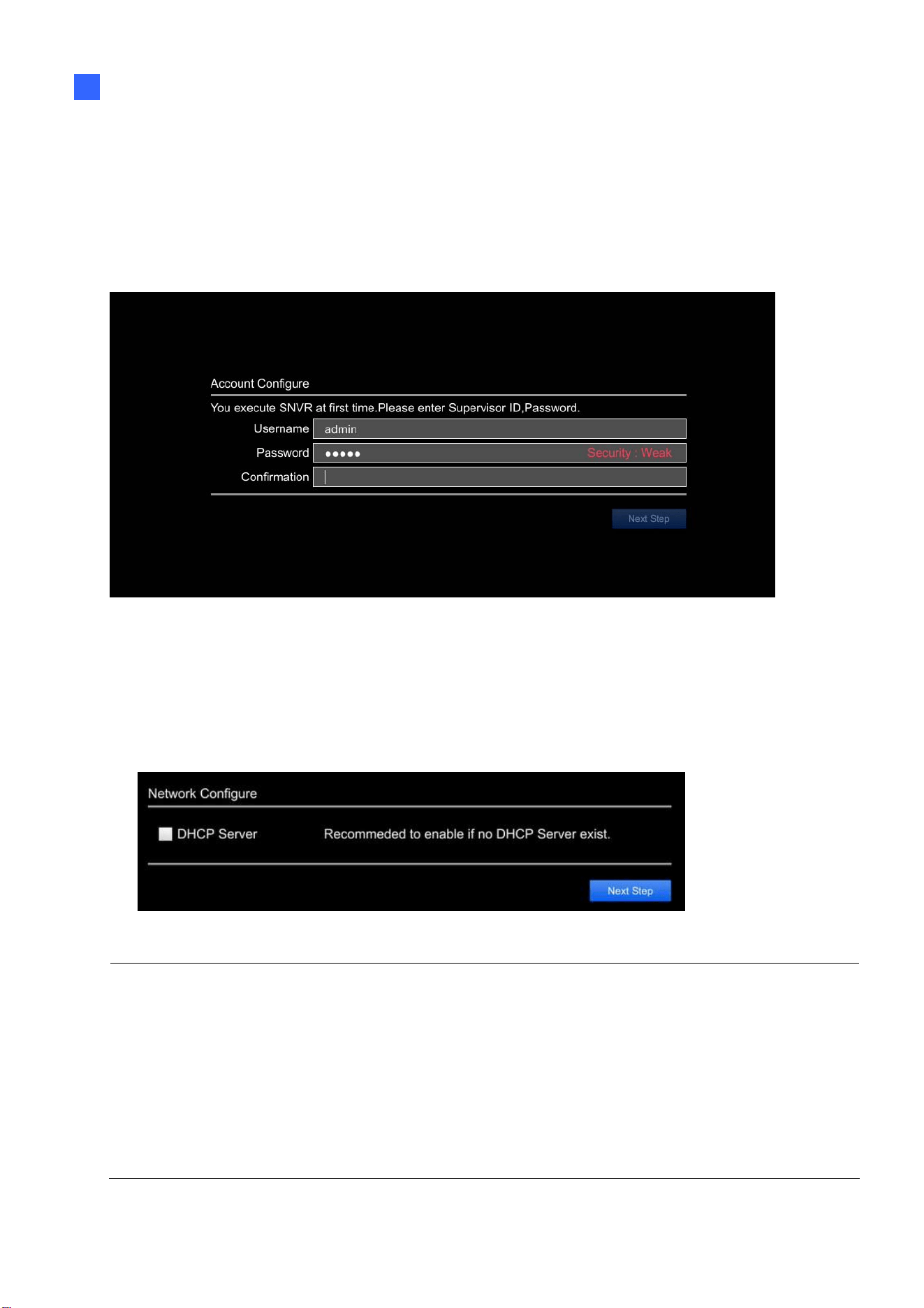
When turning on GV-SNVR for the first time or loading default settings, a login window
appears. Follow the steps below to access GV-SNVR.
Figure 2-31
1. Redefine the Username and Password for GV-SNVR by typing the desired values.
Retype your new password again and click Next to log in.
2. For GV-SNVR0411 / 0811 / 1611, enable DHCP Server to automatically assign IP
addresses for IP cameras connecting to GV-SNVR. Click Next Step to continue.
Figure 2-32
Note:
1. For GV-SNVR0412 / 0812, any IP device connected to its 4 / 8 PoE ports is automatically
assigned an IP address by its internal, isolated DHCP server, and communicates with a
network only via the SNVR.
2. GV-SNVR0412 / 0812 only, for any IP device powered by one of its 4 / 8 PoE ports, a Reboot
button is available next to the Camera Edit button for you to disconnect and reconnect the IP
device from power.
49
2.3 Setting Up IP Cameras
After installing the IP cameras under the same LAN as GV-SNVR, you can now add the
cameras to GV-SNVR.
2.3.1 Automatically Setting Up IP Cameras
To automatically set up the IP cameras, follow the steps below.
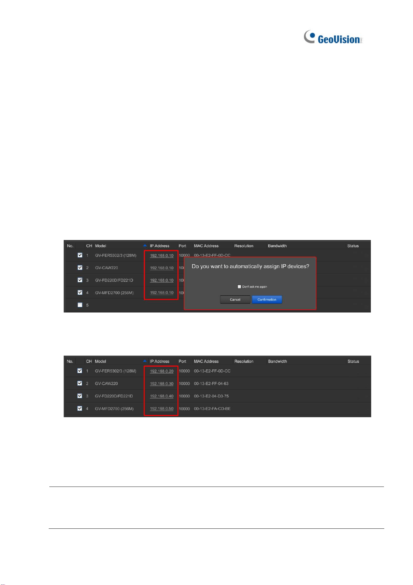
1. Upon login, GV-SNVR automatically searches and lists the IP cameras under the same
LAN.
2. For GV-SNVR0411 / 0811 / 1611 / 1612 only, you are prompted with a dialog box asking
if you want to automatically assign IP address. The automatic assignment only applies to
cameras with IP address 192.168.0.10.
Figure 2-33
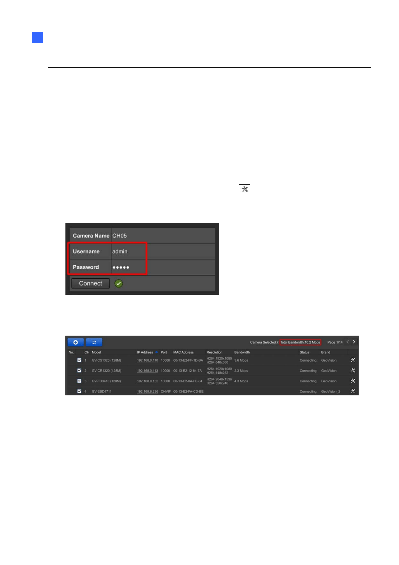
3. Click Apply. GV-SNVR assigns unused IP addresses to the cameras in an ascending
numerical order and enables the connection.
Figure 2-34
Upon successful connection, the status displays “Connected”, with the resolution and
bandwidth being displayed in the corresponding columns. Close the Camera page to access
the live view.
Note: For GV-SNVR1611 / 1612, IP cameras detected under the same LAN are listed starting
from the second page of the camera list, while the first page only displays the cameras that are
connected to the SNVR.
Getting Started
50
2
IMPORTANT:
1. By default, GV-IP Cameras use the IP address 192.168.0.10. GV-SNVR will automatically
assign unused IP addresses to these cameras to avoid IP address conflict with others under
the same LAN.
2. To connect GV-SNVR0411 / 0811 / 1611 to GV-IP Cameras, your network environment must
have a DHCP server. Or, you can enable the DHCP Server function of GV-SNVR0411 / 0811
/ 1611 to automatically assign a dynamic IP address to the cameras. For details, refer to 3.3
Network.
3. GV-SNVR connects to IP cameras with the default ID and password admin. If the IP camera
uses a different ID and password, click the Edit icon
and type the correct login
information. For GV-IP cameras without default ID and password, see 3.1.1.1 Configuring
GV-IP Cameras without Default ID and Password.
4. The total bandwidth supported varies among GV-SNVR models. For detailed specificiations,
refer to GV-SNVR datasheets. The total bandwidth can be found on the top-right corner of the
camera list.
51
2.3.2 Manually Connecting GV-IP Cameras
You can manually add GV- IP cameras to the camera list.
Note:
To connect GV-SNVR0411 / 0811 / 1611 to GV-IP Cameras, your network
environment must have a DHCP server. Or, you can enable the DHCP Server function of
GV-SNVR0411 / 0811 / 1611 to automatically assign a dynamic IP address to the cameras.
For details, refer to 3.3 Network.
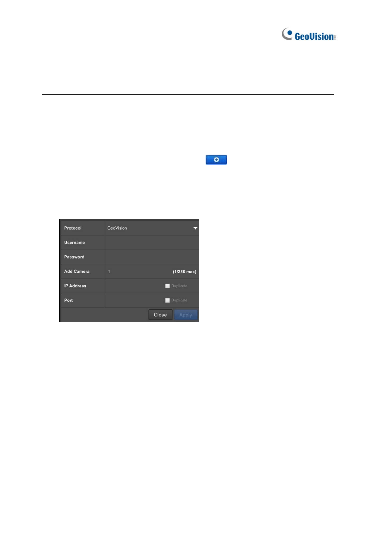
1. On the Camera page, click the Add Cameras
button.
2. Select GeoVision or GeoVision_2 protocol. GeoVision_2 protocol is for connecting to
any of the IP devices listed within the Note before Step 1.
3. Type the Username, Password, IP Address and Port of the desired IP camera. The
default port value of GV-IP Camera is 10000.
Figure 2-35
4. Click Apply to add the IP camera.
5. To add multiple cameras, repeat step 2. Type the number of cameras you want to create
in the Add Camera column.
A. To duplicate cameras with the same IP address but different ports, type the IP
address and select Duplicate for Port.
B. To duplicate cameras with the same port number but different IP addresses, type
the port number and select Duplicate for IP Address.
6. To connect GV-SNVR with the added cameras, click the box next to the CH column on
the Camera page.
Getting Started
52
2
Figure 2-36
2.3.3 Manually Connecting Third-Party IP Cameras
Note this section only applies to GV-SNVR0411 / 0412 / 0811 / 0812 / 1611 / 1612. You can
connect third-party cameras through ONVIF or RTSP protocol.
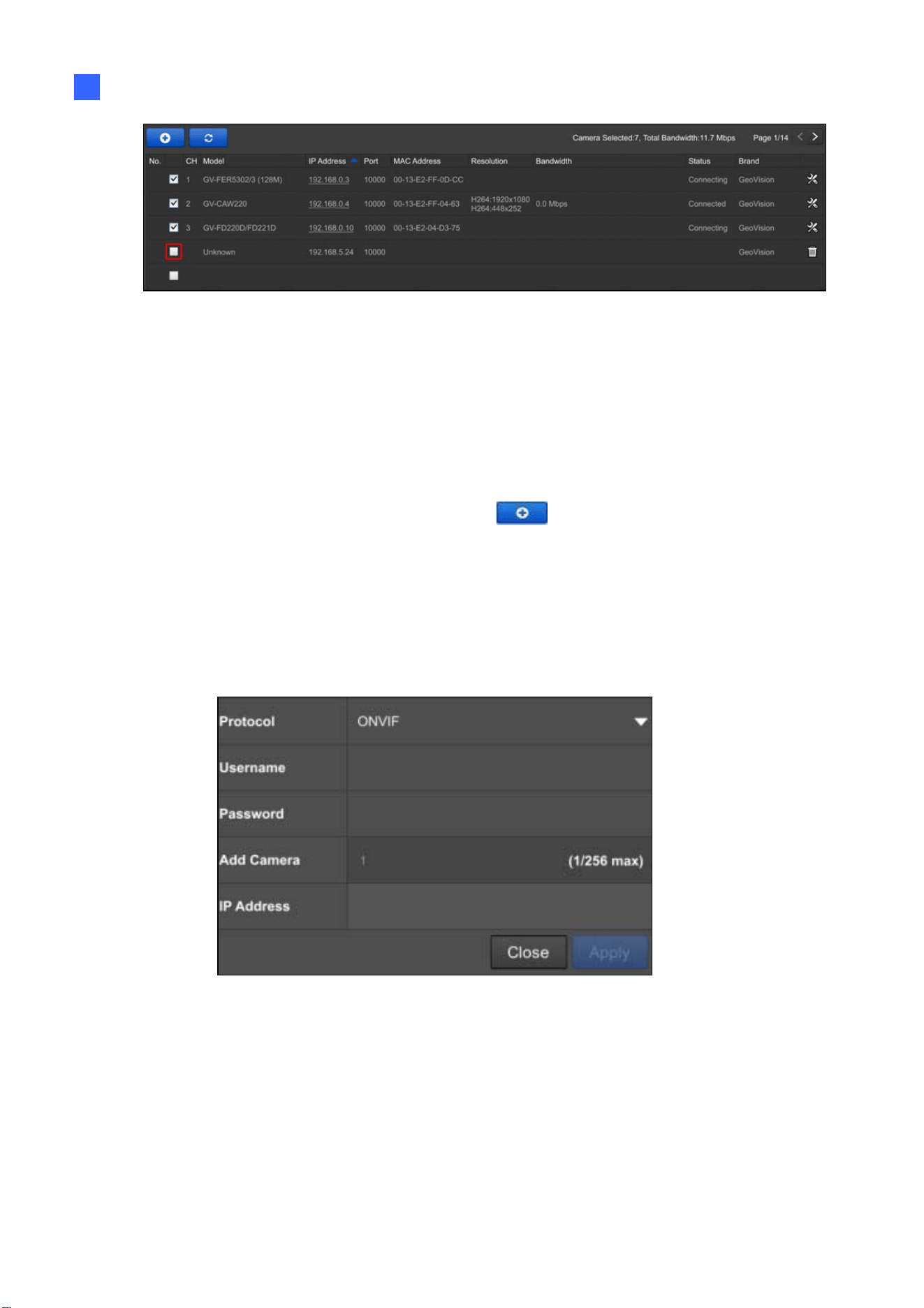
1. On the Camera page, click the Add Cameras
button.
2. Select the type of Protocol that is supported by your IP camera, ONVIF or RTSP.
3. Type the necssary information of the desired IP camera accroding to the protocol.
For ONVIF Protocol
A. Type the IP address, Username, and Password of the desired IP camera.
Figure 2-37
53
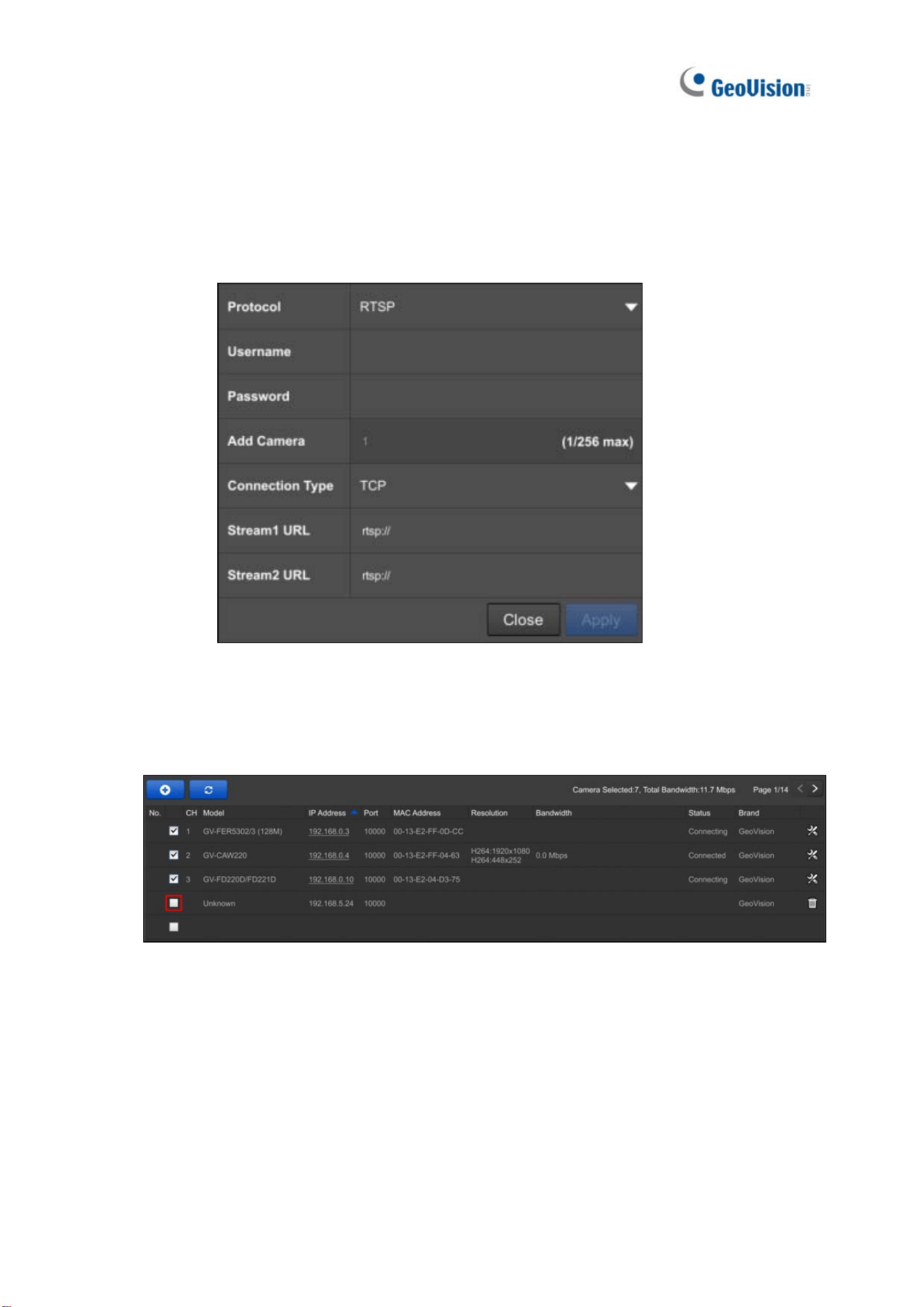
For RTSP Protocol
A. Type the Username and Password of the desired IP camera.
B. Select TCP or UDP under Type of Connection.
C. Type the RTSP URL to enable Stream1 and Stream2. For the RTSP command,
consult the documentation of the third-party IP camera.
Figure 2-38
4. Click Apply to add the IP camera.
5. To connect GV-SNVR with the added cameras, click the box next to the CH column on
the Camera page.
Figure 2-39
Getting Started
54
2
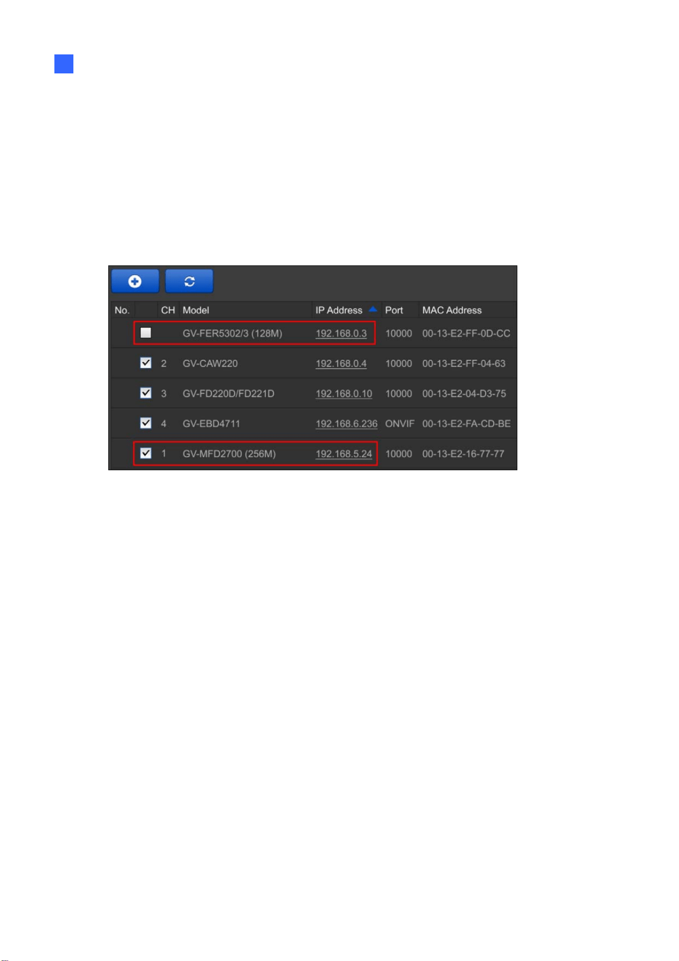
2.3.4 Changing Camera IP Address and Assigning Channels
On the Camera page, you can change the IP address of the connected cameras by clicking
on the IP address.
You can also re-assign the camera to another channel. For example, to change the camera
on Channel 1, deselect the connected camera on Channel 1 and select another camera for
connection. The selected camera is now assigned to Channel 1.
Figure 2-40
55
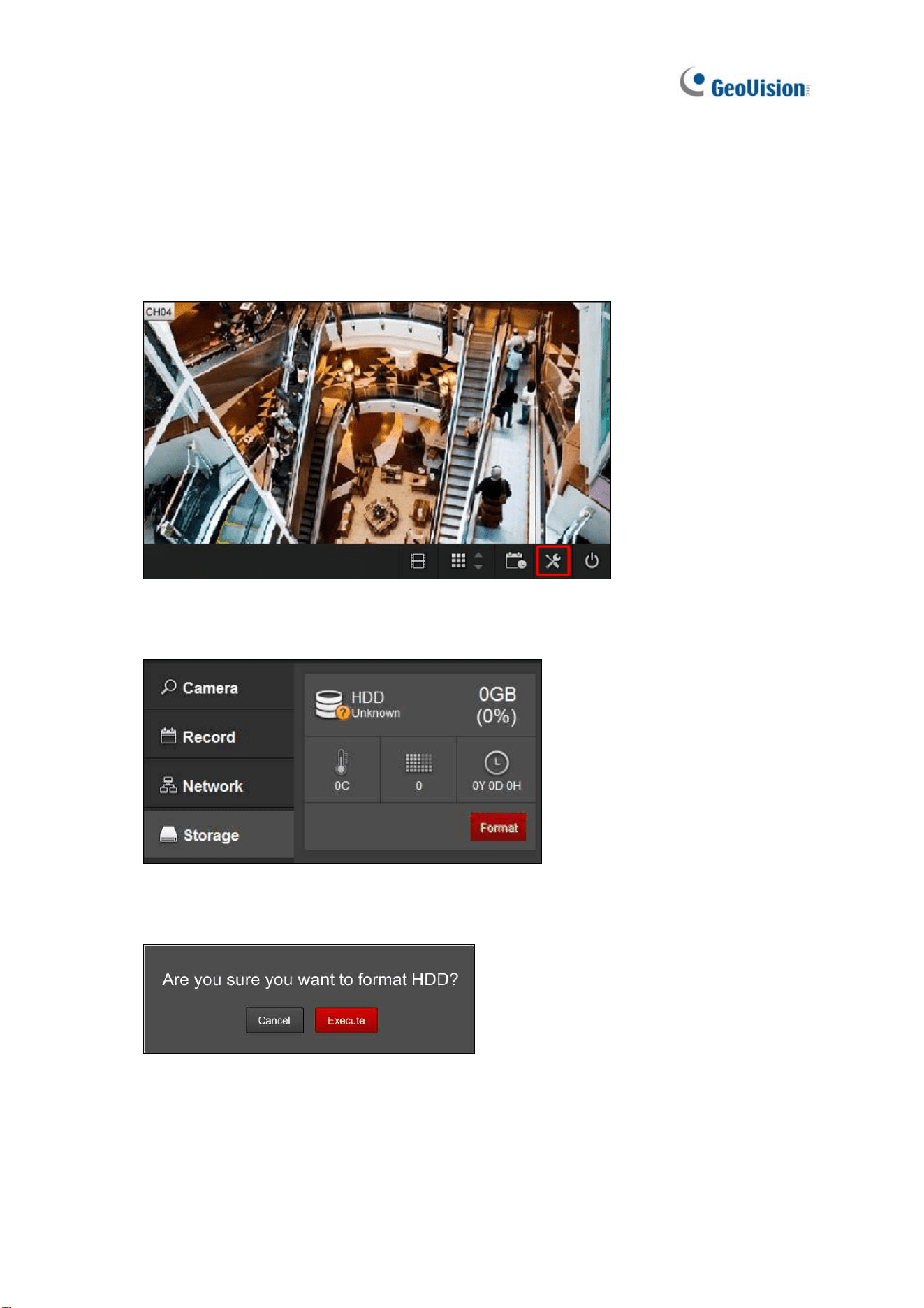
2.4 Formatting Hard Drive
After installing the hard drive to GV-SNVR, you need to format the hard drive before enabling
monitoring.
1. On the main screen, click the Setting button.
Figure 2-41
2. Select Storage.
Figure 2-42
3. Click Format. This dialog box appears.
Figure 2-43
4. Click Execute to format the hard drive.
Getting Started
56
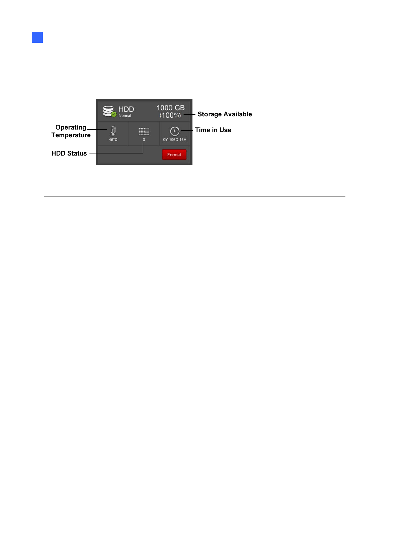
2
When the hard drive is successfully formatted, its icon should be marked with a green tick,
and the word “Normal” appears. The information of operating temperature, hard drive status
and total time in use is also displayed.
Figure 2-44
Note: When the hard drive status displays a value other than 0, replace the hard drive with
a new one to ensure proper video recording.
57
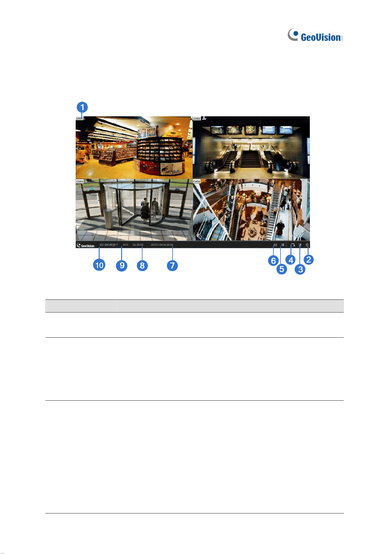
2.5 Main Screen
Close the Camera page to see the connected channels on the main screen. Here we use
GV-SNVR0811 for illustration.
Figure 2-45
No. Name Description
1 Camera Name
Indicates the camera name. The column changes from gray to red
when the recording is enabled. See Camera Name in 3.1 Camera.
2 System
Brings up the following options:
˙ Log Out
˙ Reboot (for GV-SNVR0411 / 0412 / 0811 / 0812 / 1611 / 1612
only)
˙ Shutdown (for GV-SNVR0400F / 1600 only)
3 Setting
Accesses the following setting pages:
˙ Camera (see 3.1 Camera)
˙ Recording (see 3.2 Record)
˙ Network (see 3.3 Network)
˙ Storage (see 2.4 Formatting Hard Drive)
˙ Display (see 3.5 Display)
˙ Service (see 3.6 Service)
˙ Event (see 3.7 Event for GV-SNVR0412 / 0812 / 1611 / 1612
only)

Getting Started
58
2
˙ System (see 3.8 System)
˙ Account (see 3.9 Account)
4 Record Starts / Stops monitoring.
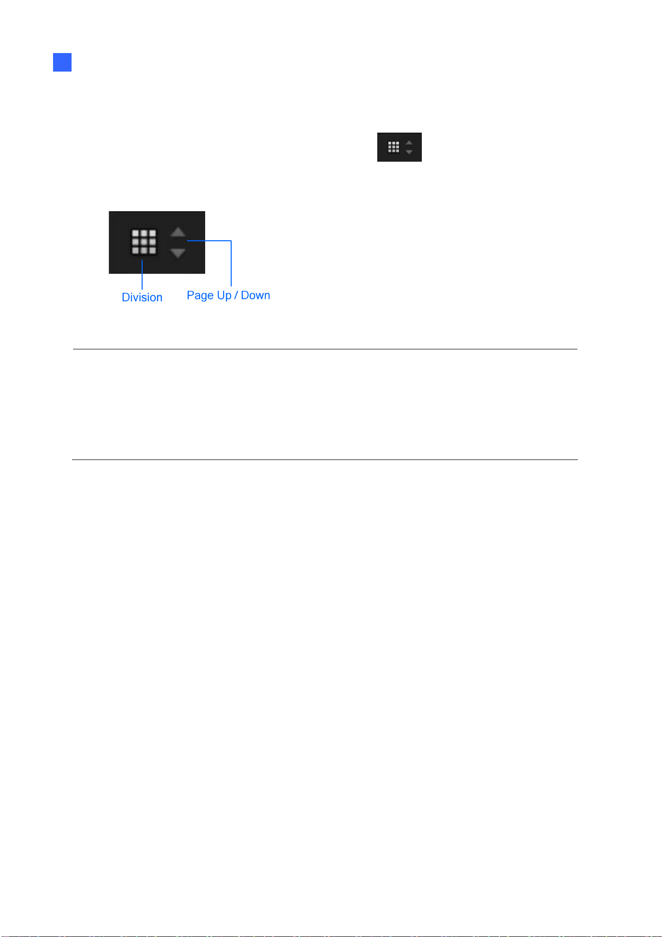
5
Division & Page
Up / Down
Selects screen divisions and switch between cameras in single
division.
6 Playback Displays the playback panel.
7 Date / Time Displays the current date and time.
8 Device Name
Displays the device name of GV-SNVR. See Device Name in 3.8
System.
9 Temperature
Displays the current temperature. This function is not applicable to
GV-SNVR1611 / 1612. For GV-SNVR0411 / 0412 / 0811 / 0812, when
the system temperature reaches 55°C (131°F) or higher, the
temperature value is displayed in red.
10 Model Name Displays the model name of GV-SNVR.
Note: For GV-SNVR0411 / 0412 / 0811 / 0812, when the system temperature reaches
above 55°C (131°F), GV-SNVR records an entry under the system log and records an
additional entry for every 3°C (°F) of increment in temperature above 55°C (131°F).

59
2.6 Enabling Recording
To start recording, click the Record button (No. 4, Figure 2-45) and select a camera. To
enable recording for all of the connected cameras, select Start All Monitoring.
By default, GV-SNVR records with Round-the-clock mode. The default recording resolution
and codec depend on the settings of each camera.
˙ To change recording mode, see 3.2 Record.
˙ To change video resolution, see 3.1 Camera.
2.7 Playing Back Video
You can instantly play back the recorded videos without interrupting monitoring and
recording.
˙ To instantly play back the recording of one single channel, click the Camera Name
(No. 1, Figure 2-45) and select Instant Playback.
˙ To instantly play back the recording of all channels, click the Playback button
(No. 6, Figure 2-45).
For detailed instructions on playing back recorded videos, refer to 4.1 Timeline Player
Getting Started
60
2
2.8 Live Monitoring
On the main screen, you can click the Division button (No. 5, Figure 2-45) and
select 1, 4, 6, 8, 9 or 16 Division. Alternatively, click on the live view of a desired camera to
switch to full screen.
Figure 2-46
Note:
1. The 6 and 8 Division modes are recommended to be used in conjuction with fisheye
dewarping for displaying Quad view in channel 1. See 2.8.5 Fisheye Dewarping.
2. In 8 Division, clicking a camera view displayed on one of the small subdivisions
switches its live view to be displayed on the large subdivision.
2.8.1 Snapshots
To take a snapshot of a live or playback video, follow the steps below.
1. Connect an USB flash drive of FAT32 format to GV-SNVR.
2. Click the camera name of a desired camera and select Snapshot. The message
“Snapshot success” pops up when the image is successfully captured and saved to the
USB flash drive.
Each image is automatically saved in JPEG format with a file name indicating the date and
time of the snapshot taken.
61
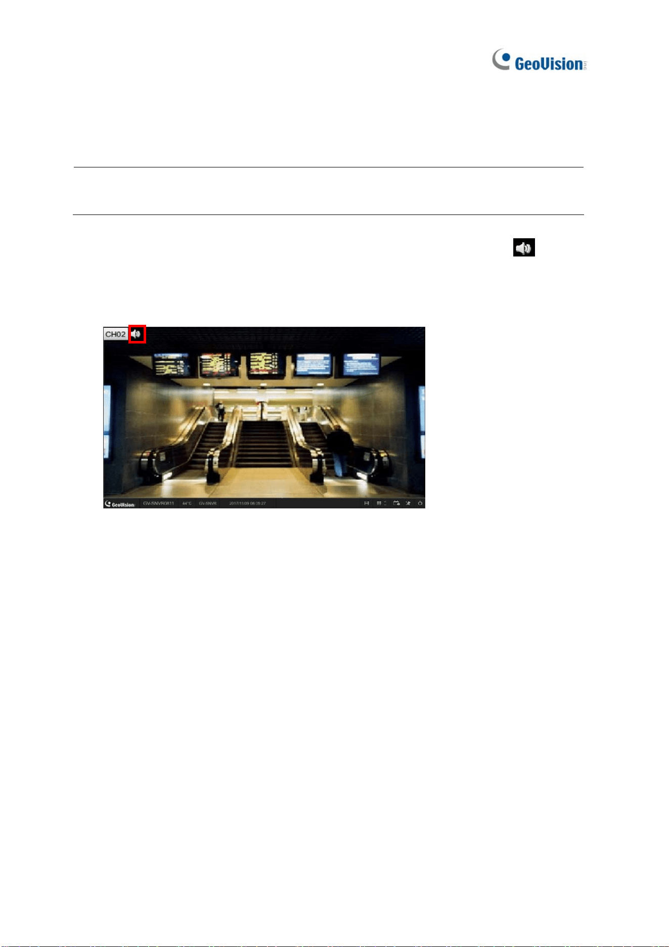
2.8.2 Audio
To enable the audio function on live video, follow the steps below.
Note: To listen to the audio of any camera, make sure the Enable Audio function is applied.
For details, see 3.1 Camera.
1. Click the name of the desired camera and select Speaker. The audio icon
appears
next to the camera name, and the audio is now accessible.
2. To access the audio of a different camera, repeat step 1. The audio of the previous
camera is turned off automatically.
Figure 2-47
Getting Started
62
2
2.8.2.1 Using Microphone on GV-SNVR0412 / 0812 / 1611 / 1612
To use the microphone function of GV-SNVR0412 / 0812 / 1611 / 1612, follow the steps
below.
Note: To transmit audio to the speaker of any camera using the microphone of GV-SNVR,
make sure of the following
The camera supports speaker function and is connected to a speaker.
A microphone is connected to the Audio In port of GV-SNVR0412 / 0812 / 1611 /
1612. See 2.2 Connecting GV-SNVR.
The Enable Audio function is applied. For details, see 3.1 Camera.
1. Click the camera name of the desired camera and select Microphone. The microphone
icon
appears next to the camera name, and the audio is now accessible.
2. To transmit audio to a different camera, repeat step 1. The microphone function of the
previous camera is turned off automatically.
Figure 2-48
63
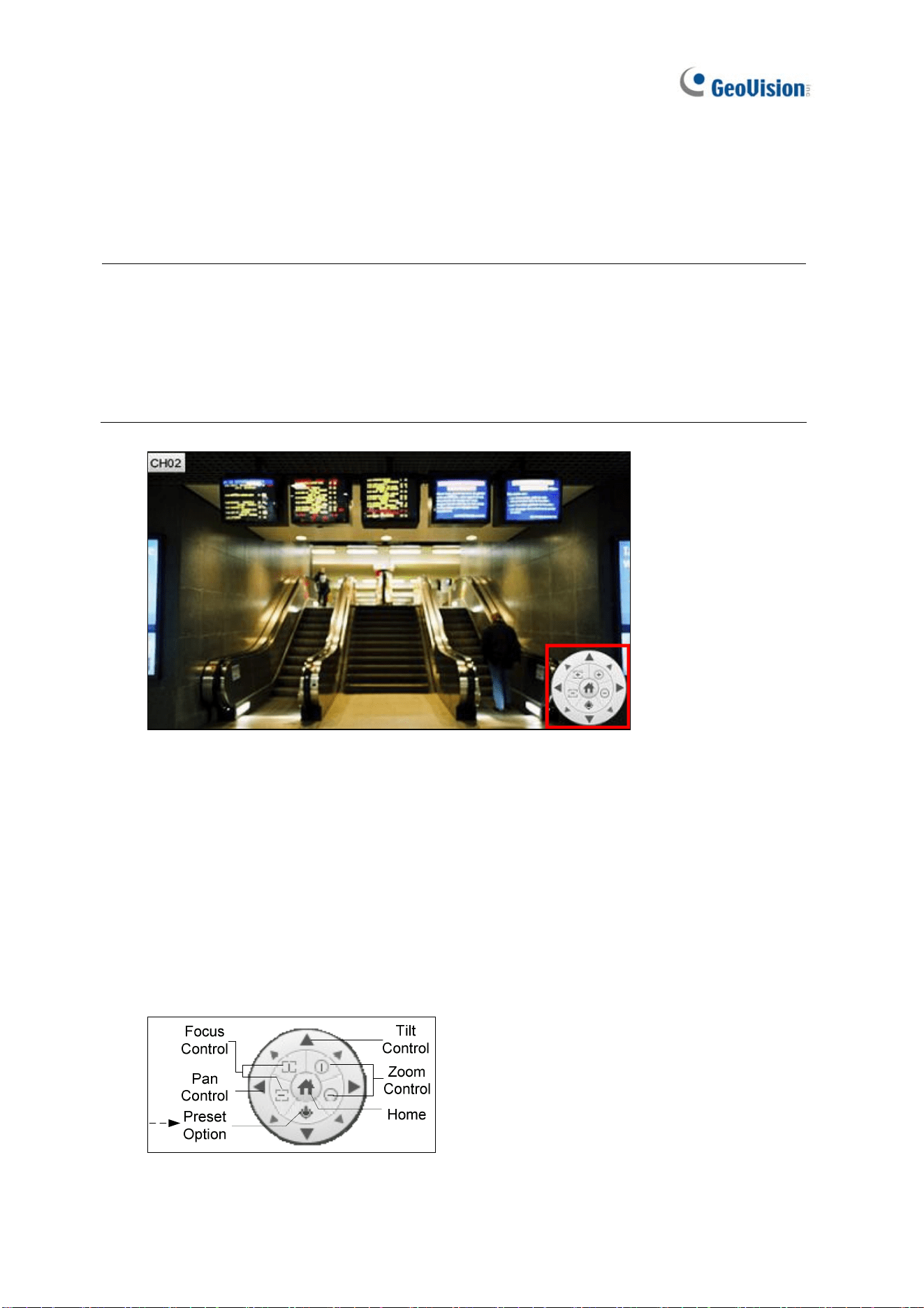
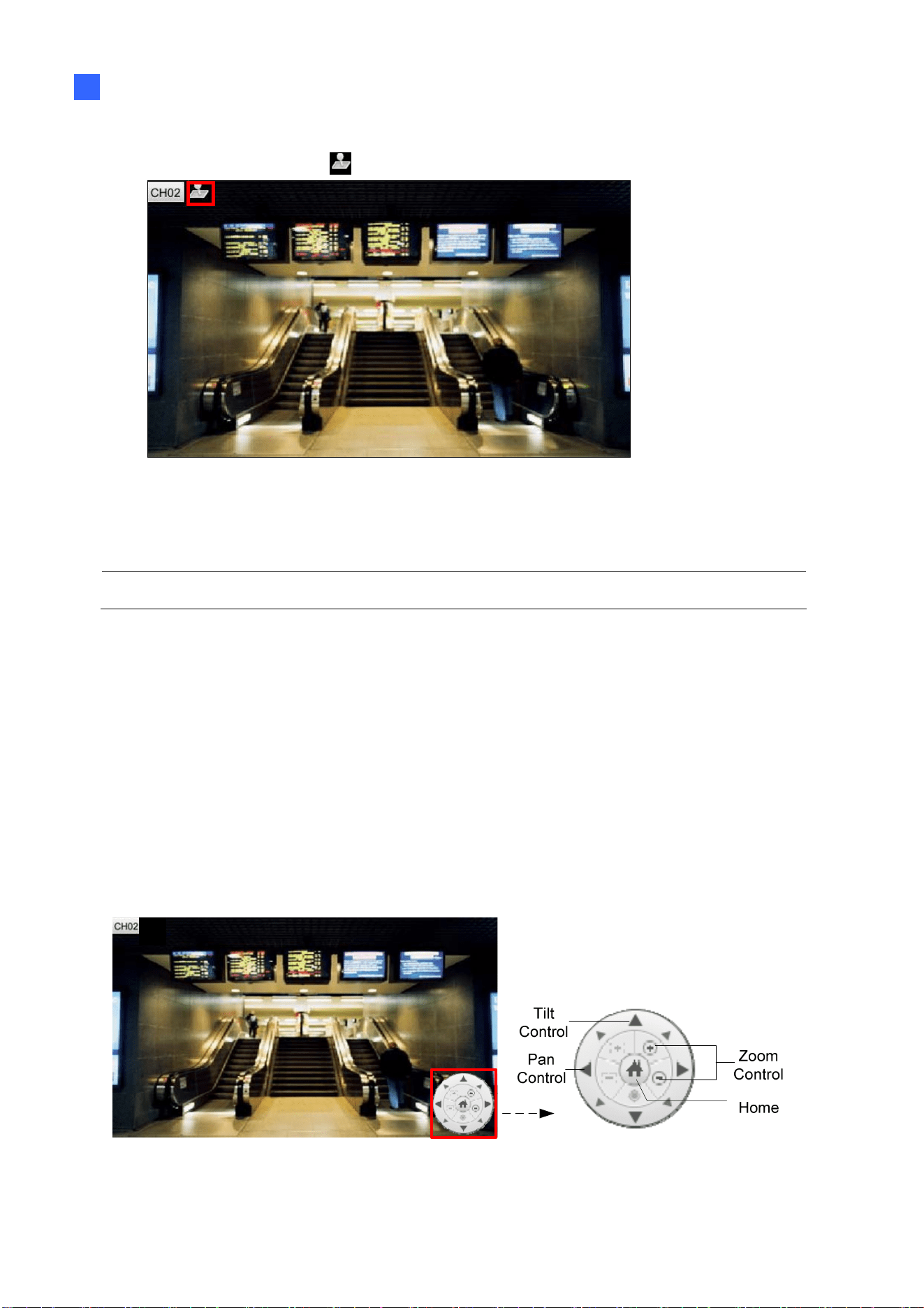
2.8.3 PTZ Control
To enable the PTZ function on live view, click the camera name of the desired camera and
select PTZ. The PTZ control panel appears at the lower-right corner of the live view.
Note:
1. This is only available for cameras supporting PTZ functions.
2. The live view and PTZ control functions of GV-SD200 / 200-S / 2411 / 2322-IR / 3732-IR
/ 4825-IR / 4834-IR can be accessed through GV-SNVR0411 / 0811 firmware V2.63 or
later.
Figure 2-49
Home: Brings the PTZ live view back to the Home position.
Pan/Tilt Control: Allows the camera to pan and tilt to any angle.
Zoom Control: Allows the camera to zoom in or out.
Focus Control: Adjusts the camera to focus in or out.
Preset Option: Moves the camera to a preset point by entering a preset number using
the onscreen keypad.
Figure 2-50
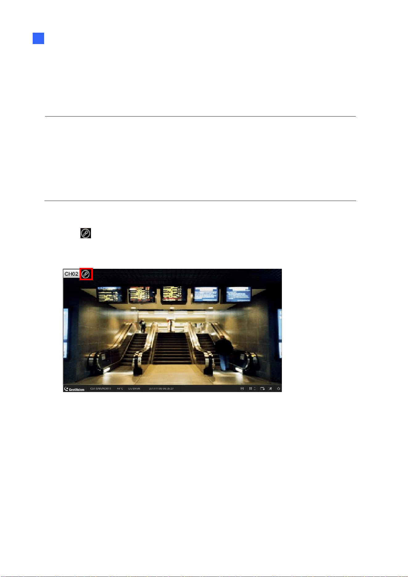
To enable PTZ control, you can also use GV-Joystick V2, a plug-and-play device used to pan,
Getting Started
64
2
tilt, zoom and focus a PTZ camera. When GV-Joystick V2 is connected to the USB port on
GV-SNVR, the Joystick icon
will appear beside the camera name.
Figure 2-51
For details on GV-Joystick V2, see GV-Joystick V2 User’s Manual.
Note: GV-SNVR does not support GV-Keyboard.
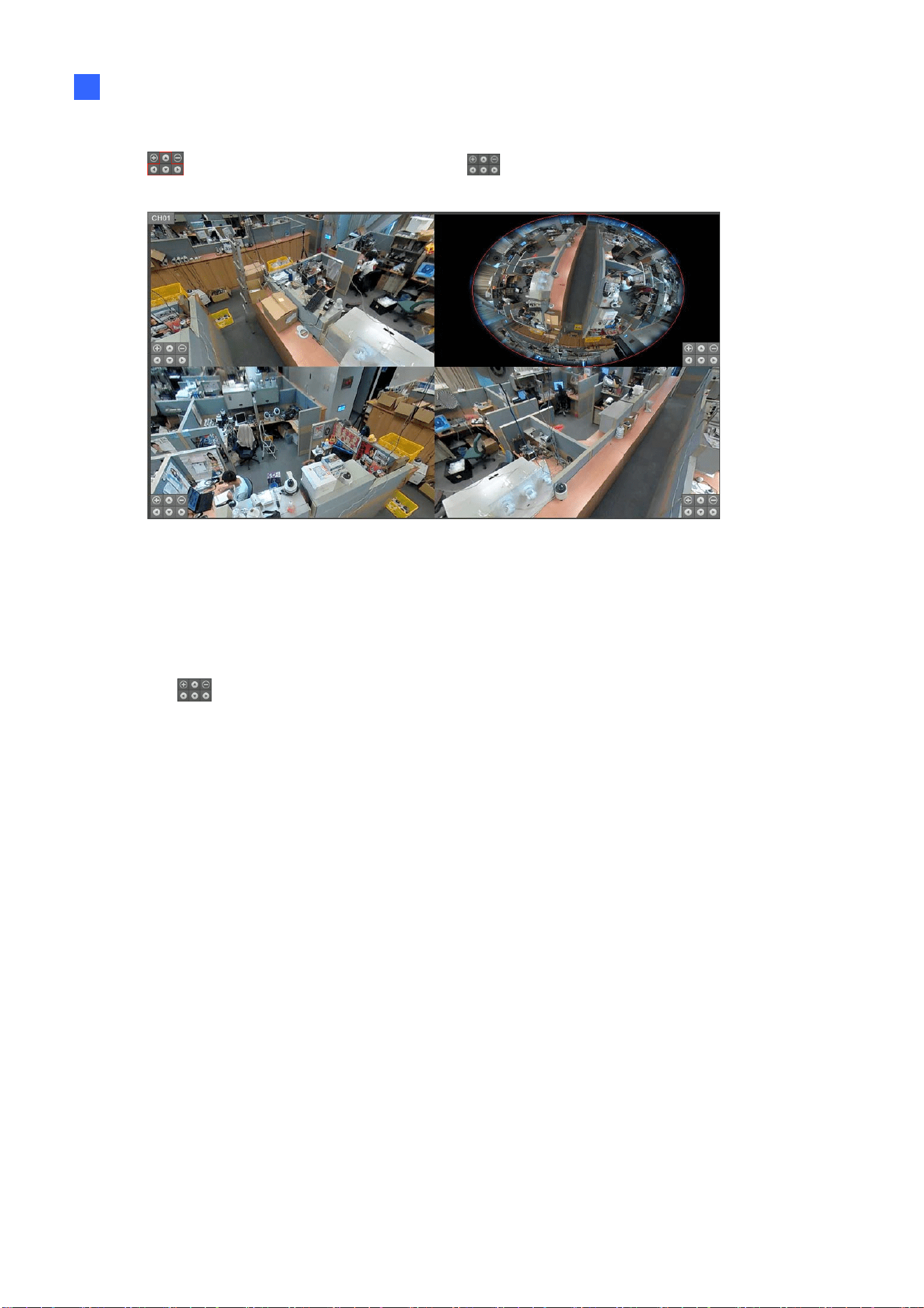
2.8.4 Digital PTZ Function
Note this section is only applicable to GV-SNVR1600.
To enable the DPTZ function on live video, click the camera name of the desired camera and
select Enable Digital PTZ. The PTZ control panel appears at the lower-right corner of the
live view.
Click the Zoom In button first and then click Tilt and Pan buttons to move the camera view.
Figure 2-52 Figure 2-53

65
Home: Brings the DPTZ live view back to the Home position.
Pan/Tilt Control: Allows you to pan and tilt on the live view.
Zoom Control: Allows you to zoom in or out on the live view.
Note:
1. The Focus Control and Preset functions are not supported.
2. The DPTZ function is only available for non-PTZ cameras.
2.8.5 Fisheye Dewarping
Only for GV-SNVR0411 / 0412 / 0811 / 0812 that connects to GeoVision IP Fisheye cameras.
A fisheye camera allows you to cover all angles of a location with just one camera. Using
different fisheye view modes, the distorted hemispherical image produced by the fisheye
camera can be converted to a conventional rectilinear projection.
Note:
1. Fisheye Dewarping is not supported when the channel resolution is configured to 4K.
2. Only one fisheye camera can be dewarped by GV-SNVR at a time.
To enable fisheye dewarping on live video, click the camera name of a fisheye camera and
select Enable fisheye dewarping. Click the camera name again to see the following
options.
Camera Modes: You can choose among four view modes: Quad view (Default), Single
view, 360 degree, 180 degree. For details, see 5.1.7 Fisheye View.
Getting Started
66
2
Image Alignment: On the upper-right square of the Quad view, click any button from
, and the red circle appears. Use the to align the red circle with the edge of
the camera image. For details, see 5.1.7 Fisheye View.
Figure 2-54
Camera Position: Select Ceiling, Wall, or Floor according to where the camera is
mounted.
Reset: Restore to Quad view setting.
Use the
to zoom in, zoom out or adjust the direction of the camera image.
2.8.6 Image Orientation
Note this section is only applicable to GV-SNVR0411 / 0412 / 0811 / 0812 / 1611 / 1612.
To rotate the image of a live or recorded video with the image orientation function, click the
camera name of a desired camera, select Image Orientation and choose the desired
rotation angle.
67
Chapter 3 System Configuration
This section introduces the following settings: Camera, Record, Network, Storage, Display,
Service, System, and Account.
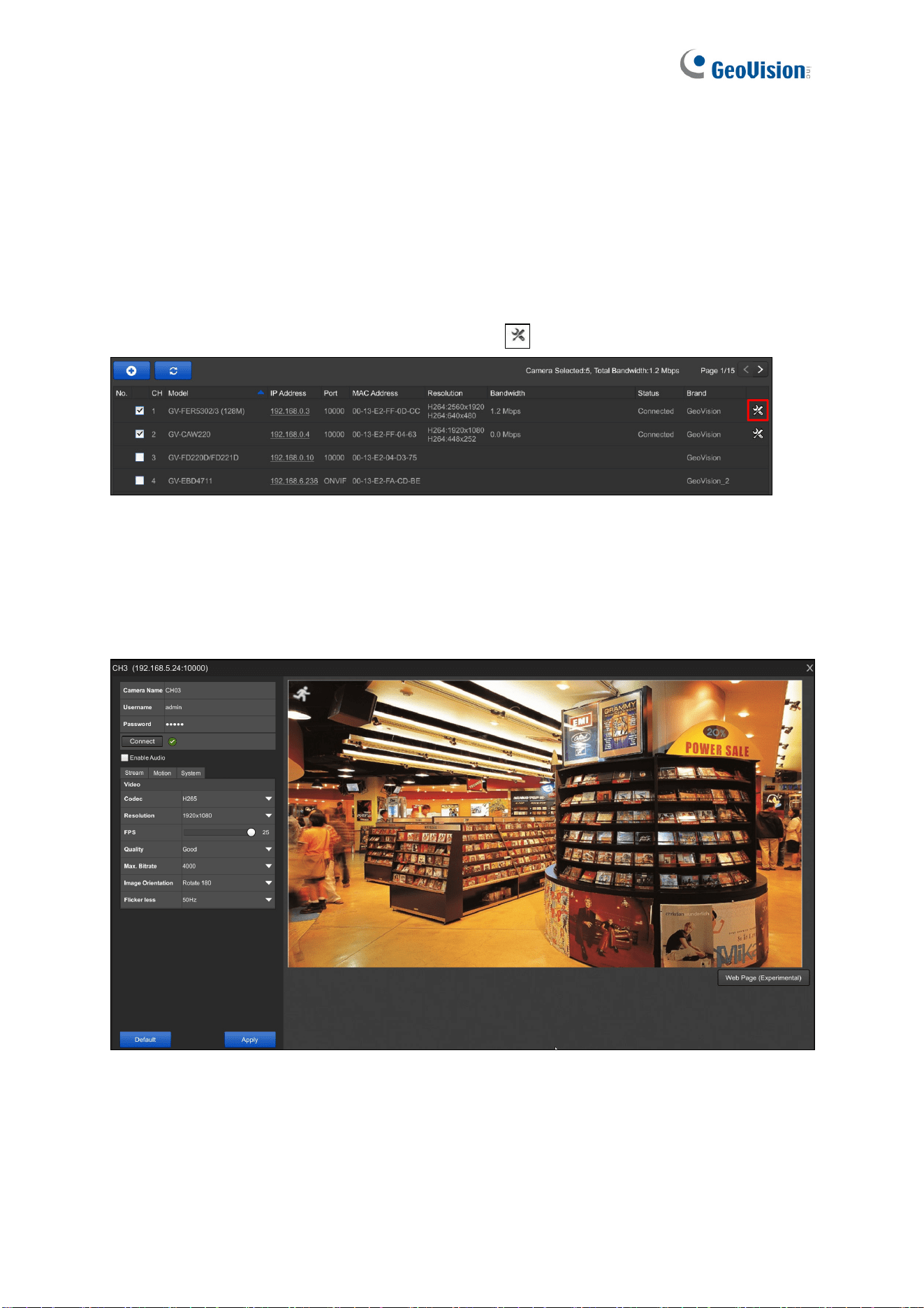
3.1 Camera
To access the camera settings, click the Edit button of the camera on the Camera page.
Figure 3-1
The Camera Settings page appears.
3.1.1 GV-IP Camera Settings
Figure 3-2
Camera Name: Name the camera.
Username: Type the username of the camera. The default is admin.
Password: Type the password of the camera. The default is admin.
Enable Audio: Click to enable audio streaming.

System Configuration
68
3
[Stream]
Codec: For GV-SNVR0411 / 0412 / 0811 / 0812 / 1611 / 1612, select video codec
between H.264 and H.265. For GV-SNVR0400F / 1600, the video codec is H.264.
Resolution: Select the video resolution for the camera.
FPS: Set up recording frame rate for the camera.
Quality: Select the level of video quality.
Max. Bit Rate: Set up the maximum bit rate of video stream.
Image Orientation: Adjust the image orientation by selecting Normal, Horizontal
Mirror, Vertical Flip or Rotate 180.
Flicker less: The frequency of your camera’s image is automatically matched with the
frequency of indoor light sources, e.g. fluorescent lighting. You can also select 50 Hz or
60 Hz manually. If the frequencies don’t match, faint light or dark bars may appear in
your images. Check the power utility to determine which frequency is used.
[Motion]
Motion Area: Draw up to 8 areas with different sensitivity values on the image for
motion detection.
Motion Sensitivity: Configure the sensitivity value from 1 to 10 for the motion
detection. The higher the value, the more sensitive the camera is to motion.
[System]
Password: Only for GV-SNVR0411 / 0412 / 0811 / 0812 / 1611 / 1612. Change the
password of the camera by typing in a desired password.
To enable adjusted settings, click Apply.
Only for GV-SNVR0411 / 0412 / 0811 / 0812 / 1611 / 1612. To load the camera’s default
settings, click Default.
Note:
1. For the FPS function, GV-SNVR supports up to 30 fps.
2. After loading default, the IP camera will restart and may take some time to reconnect.
3. The Web Page button is intended for configuring the login info of GV-IP cameras
without default ID and password and accessing of third-party camera’s web address.
See 3.1.1.1 Configuring GV-IP Cameras without Default ID and Password.
69
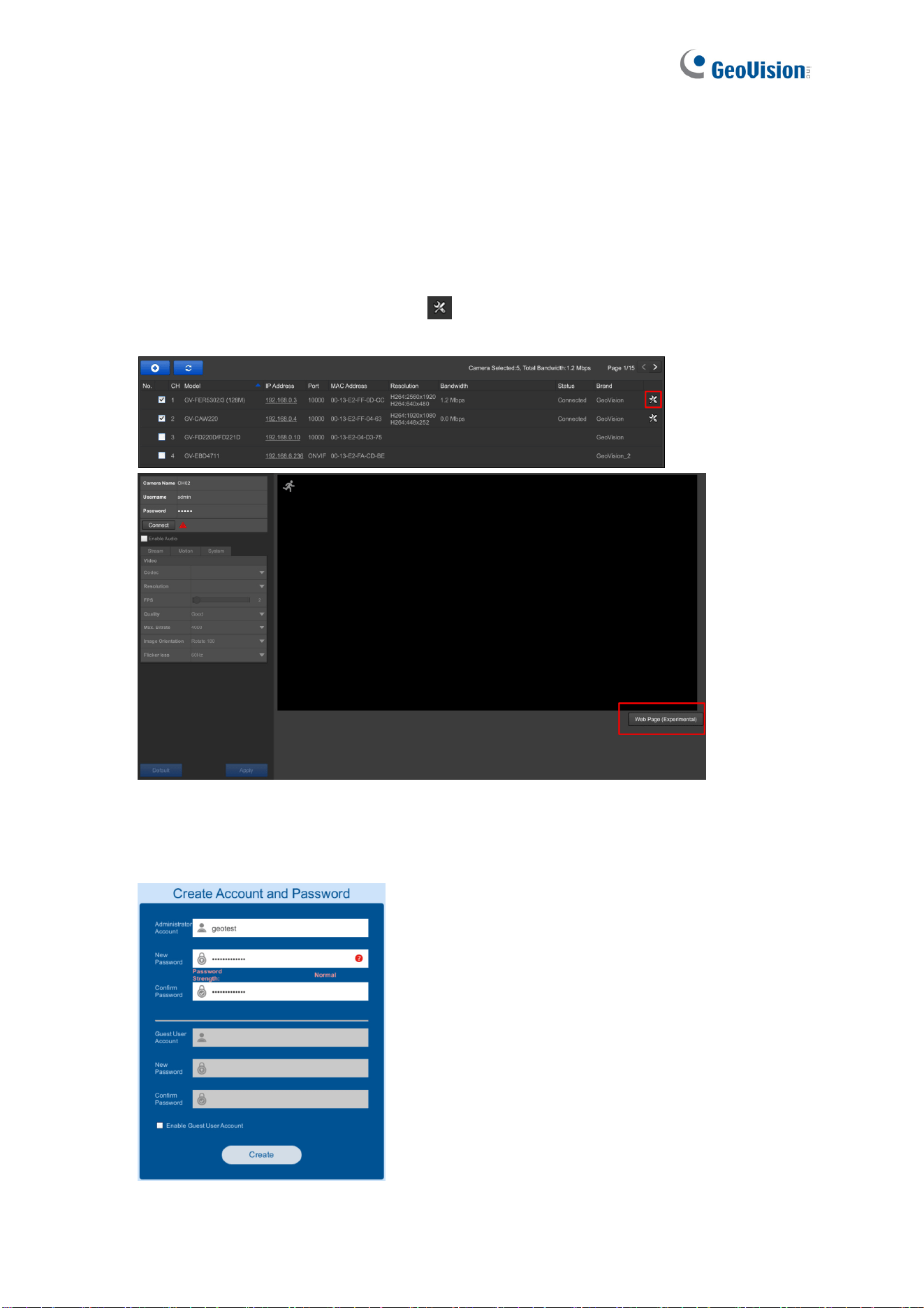
3.1.1.1 Configuring GV-IP Cameras without Default ID and Password
Only for GV-SNVR0411 / 0412 / 0811 / 0812 / 1611. For GV-IP cameras without default ID
and password, follow the steps below to configure the cameras from GV-SNVR.
1. Once connected, click the Edit button
next to the camera you want to configure and
click Web Page.
Figure 3-3
2. Fill in the required information in the account setup page of GV-IP camera and click
Create.
Figure 3-4
System Configuration
70
3
3. Close the account setup page, type the Username and Password set and click
Connect.
Figure 3-5
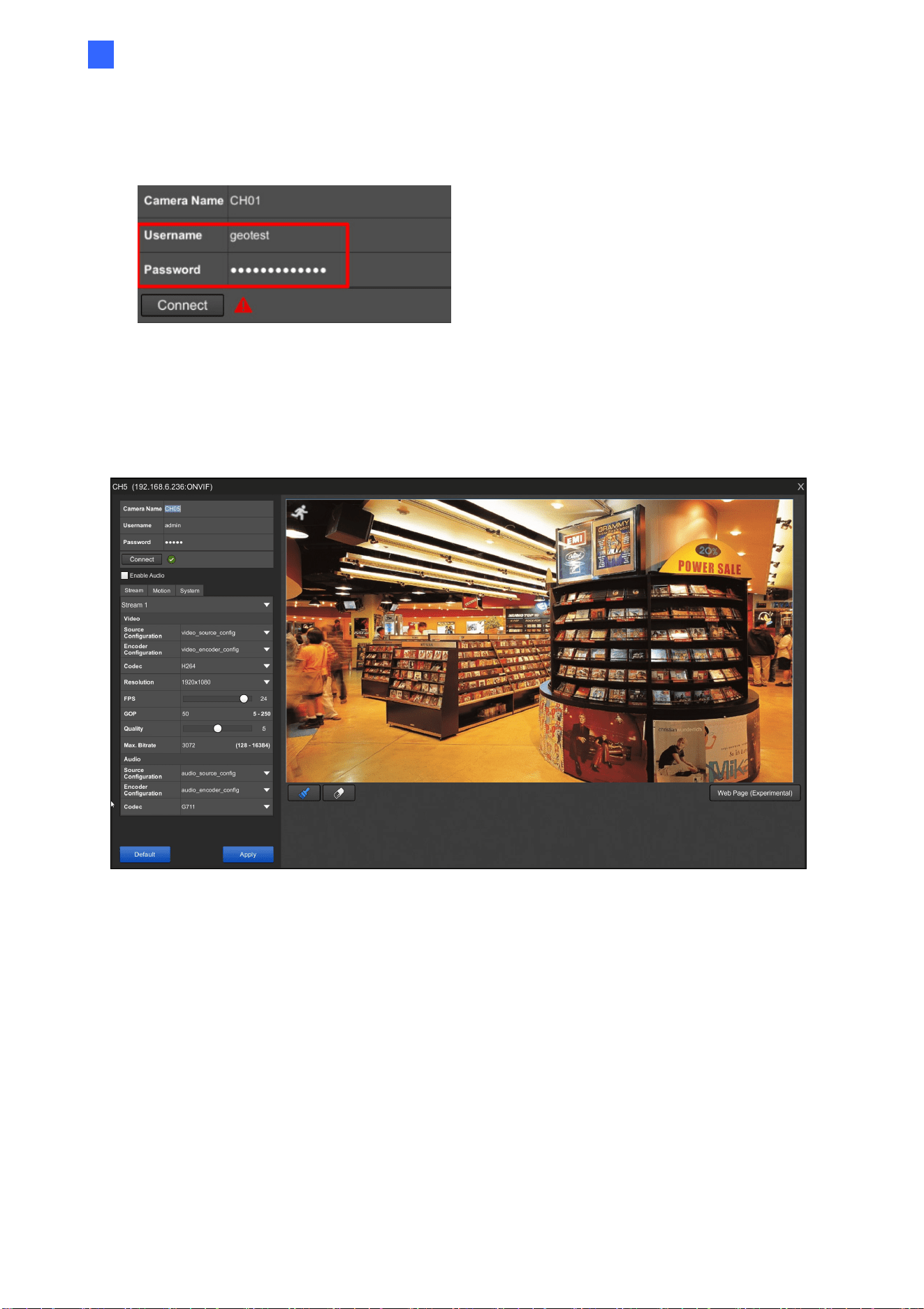
3.1.2 Third-Party IP Camera Settings (ONVIF)
Figure 3-6
Camera Name: Type a desired name for the camera.
Username: Type the username of the camera. The default is admin.
Password: Type the password of the camera. The default is admin.
Enable Audio: Click to enable audio streaming.
[Stream]
Stream: Select a video stream to configure.

71
Video
Source Configuration: The Source Configuration displays type of video source of the
camera connected.
Encoder Configuration: The Encoder Configuration displays the type of video
encoding of the camera connected.
Codec: For GV-SNVR0411 / 0412 / 0811 / 0812 / 1611 / 1612, select video codec
between H.264 and H.265. For GV-SNVR0400F / 1600, the video codec is H.264.
Resolution: Select the video resolution for the camera.
FPS: Set up recording frame rate for the camera.
GOP: Set the maximum number of seconds, from 5 to 250, between every key frame.
The higher the value, the lower number of key frames within a time interval.
Quality: Select the level of video quality.
Max. Bit Rate: Set up the maximum bit rate of video stream.
Audio
Source Configuration: The Source Configuration displays type of audio source of the
camera connected.
Encoder Configuration: The Encoder Configuration displays the type of audio
encoding of the camera connected.
Codec: The audio codec supported by GV-SNVR is G.711.
[Motion]
Motion Area: Draw a specified area on the image for motion detection.
Motion Sensitivity: Configure the sensitivity value for the motion detection.
[System]
Password: Only for GV-SNVR0411 / 0412 / 0811 / 0812 / 1611 / 1612. Change the
password of the camera by typing in a desired password.
To enable adjusted settings, click Apply.
Only for GV-SNVR0411 / 0412 / 0811 / 0812 / 1611 / 1612. To load the camera’s default
settings, click Default.
System Configuration
72
3
Note:
1. For the FPS function, GV-SNVR supports up to 30 fps.
2. After loading default, the IP camera will restart and may take some time to reconnect.
3. Camera settings that can be configured through GV-SNVR may vary with different
camera models.
4. When the camera does not support motion detection, the message “Not supported by
camera” is shown.
5. The Web Page button is intended for configuring the login info of GV-IP cameras
without default ID and password and accessing of third-party camera’s web address.
See 3.1.1.1 Configuring GV-IP Cameras without Default ID and Password.
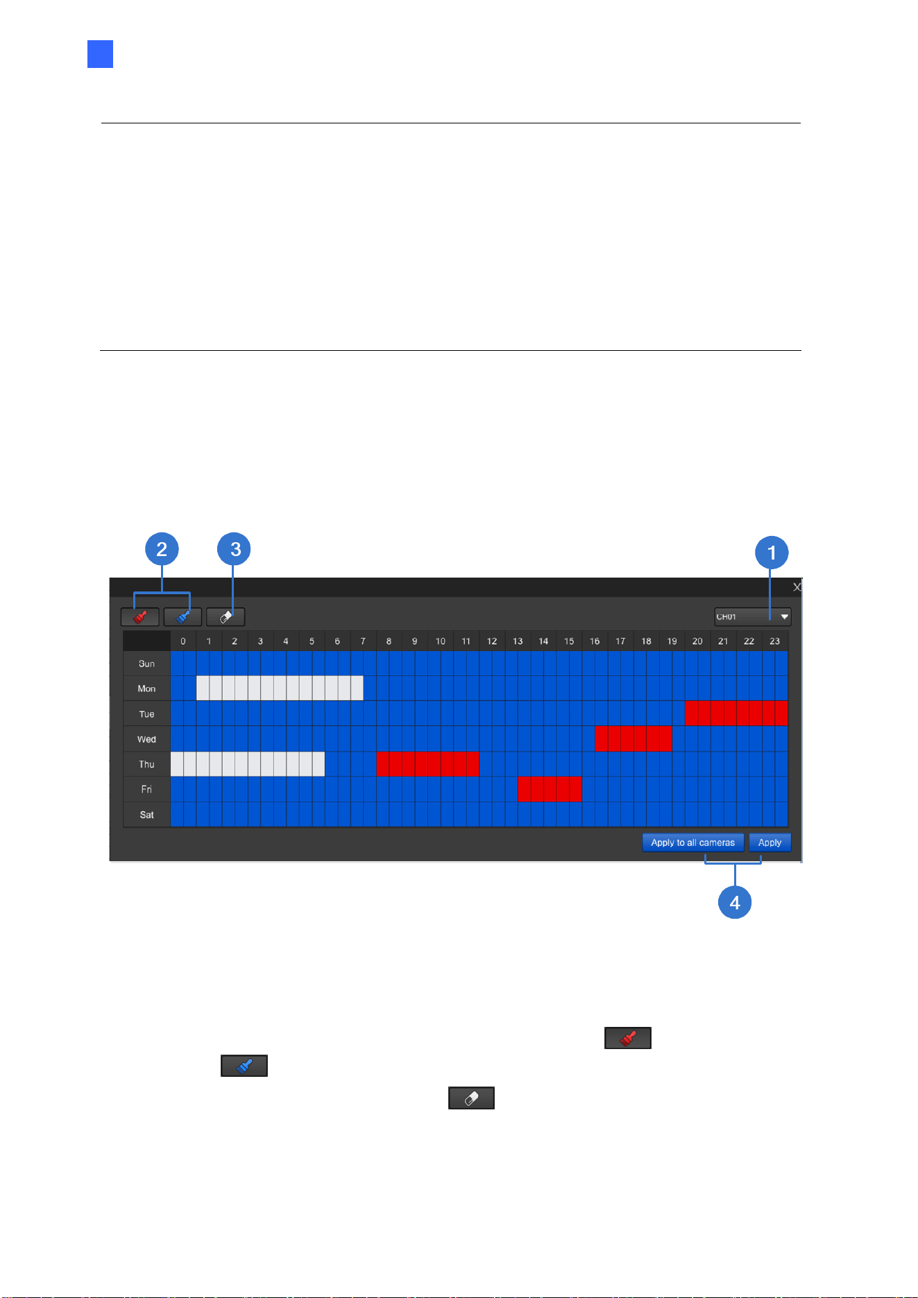
3.2 Record
You can set up desired recording modes for specific periods on specific days for each
connected camera. The default recording mode is round-the-clock.
Figure 3-7
1. Select a camera from the drop-down list at the upper-right corner.
2. To set up a recording mode, click the Motion Recording icon
or Round-the-
clock icon
and drag the cursor on the desired period.
3. To clear the settings, click the Clear icon
and drag the cursor on the desired
period.
4. Click Apply or Apply to all cameras as needed to enable the settings.
73
3.3 Network
The Network settings includes basic network configurations that enable GV-SNVR to be
connected to a network. By default, GV-SNVR is assigned with a dynamic IP address when
connecting to the network.
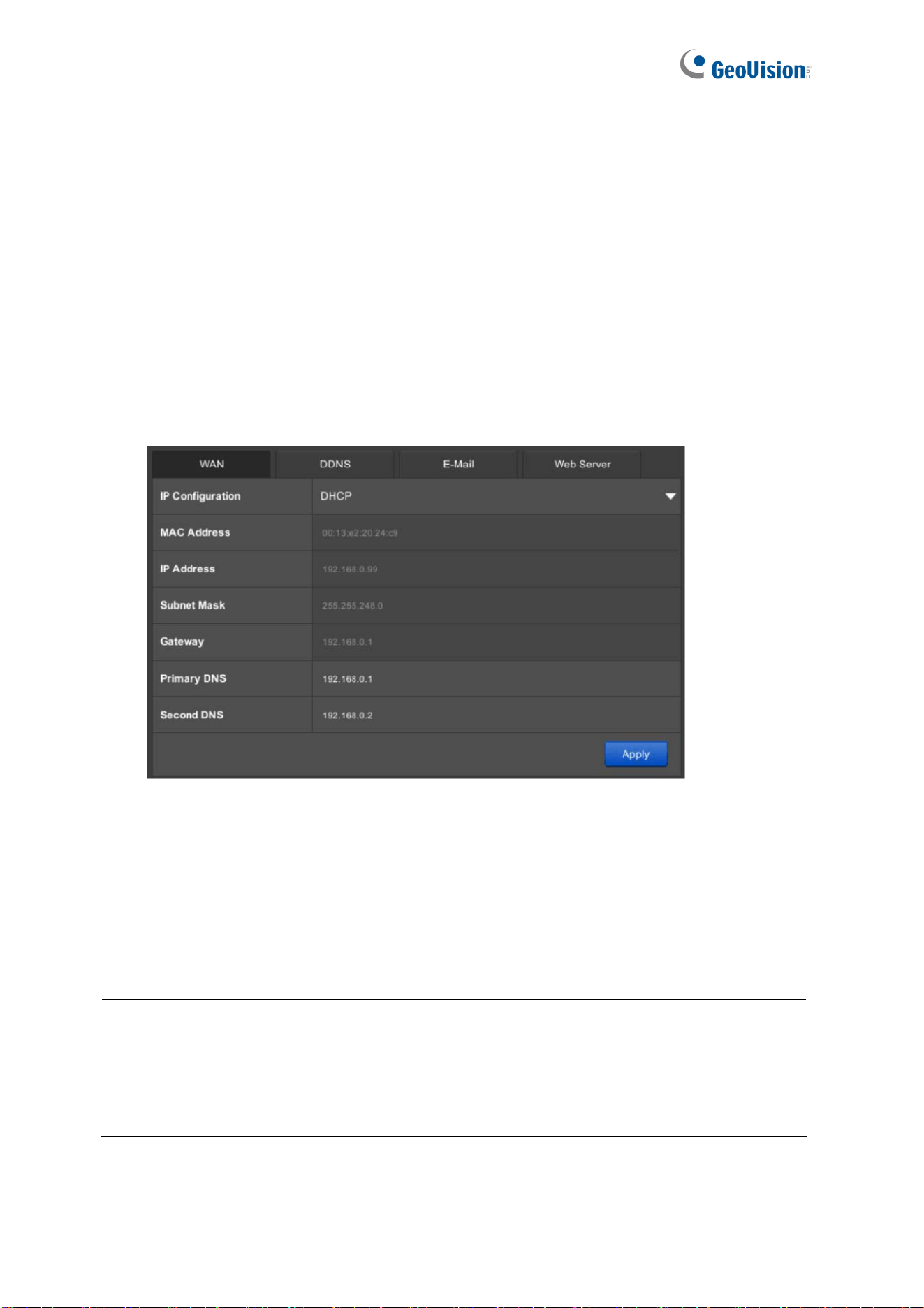
3.3.1 WAN / LAN
[LAN / WAN] The Settings can be found under the LAN or WAN tab depending on the
model of your GV-SNVR. The following is exemplified using GV-SNVR0812.
Figure 3-8
IP Configuration: Select DHCP or Static according to your network environment.
MAC Address: Displays the MAC Address of GV-SNVR.
DHCP Server: (Only for GV-SNVR0411 / 0811 / 1611) Select Enable or Active to
automatically assign a dynamic IP address to the connected cameras.
Note:
1. The DHCP Server function cannot be used in a network environment with DHCP
servers.
2. After enabling the DHCP Server function, the IP Configuration setting of your GV-
SNVR’s LAN will be changed to Static IP automatically and the IP Address will be
fixed. The default static IP address is 192.168.0.100 or 192.168.100.100.
To assign a static IP address, select Static and fill out the required settings below.

System Configuration
74
3
IP Address: Type a static IP address for GV-SNVR. The default is 192.168.0.100 (or
192.168.100.100 for GV-SNVR1611).
Subnet Mask: Type a subnet mask. The default is 255.255.255.0.
Gateway: Type a gateway. The default is 192.168.0.1.
Primary DNS: Type a primary DNS. The default is 192.168.0.1 (or 192.168.100.101 for
GV-SNVR1611).
Second DNS: Type a second DNS. The default is 192.168.0.2 (or 192.168.100.250 for
GV-SNVR1611).
Only for GV-SNVR1600, to enable the PPPoE connection, select PPPoE and fill out the
required settings below.
Primary DNS: Type a primary DNS. The default is 192.168.100.1.
Second DNS: Type a second DNS. The default is 192.168.100.2.
PPPoE Username: Type the username you have registered for PPPoE.
PPPoE Password: Type the password you have registered for PPPoE.
IMPORTANT: For GV-SNVR1600, when both LAN and WAN are applied simultaneously,
note the following:
Only WAN can be connected to the Internet.
Only the IP Cameras under the same LAN can be searched by GV-SNVR1600. To
connect with the IP cameras under WAN, you must add the cameras manually. For
details, see 2.3.2 Manually Connecting IP Camera.
Click Apply. GV-SNVR is now accessible by entering the assigned IP address on Web
browser.
75
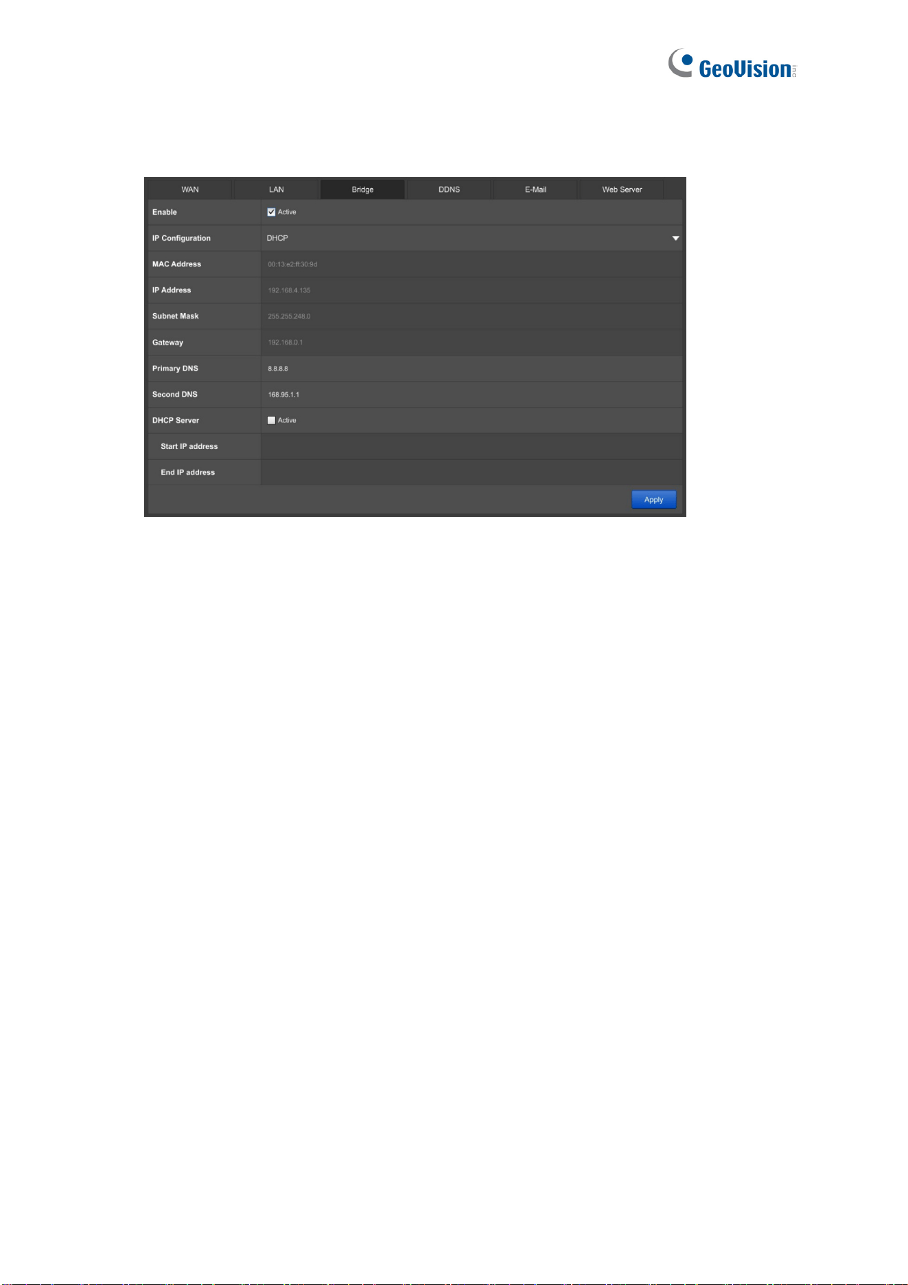
[Bridge] only for GV-SNVR1611
Figure 3-9
Enable: Select Active to establish a bridge connection between the WAN and LAN of
GV-SNVR.
IP Configuration: Select DHCP or Static according to your network environment.
MAC Address: Displays the MAC Address of GV-SNVR.
DHCP Server: Select Active to automatically assign a dynamic IP address to the
connected cameras.
Set the range of the IP addresses for the connected cameras by defining the Start
IP Address and End IP Address. The default of each is 192.168.0.101 and
192.168.0.250.
To assign a static IP address, select Static IP for IP Configuration and fill out the required
settings below.
IP Address: Type a static IP address. The default is 192.168.0.100.
Subnet Mask: Type a subnet mask. The default is 255.255.255.0.
Gateway: Type a gateway. The default is 192.168.0.1.
Primary DNS: Type a primary DNS.
Second DNS: Type a second DNS.
System Configuration
76
3
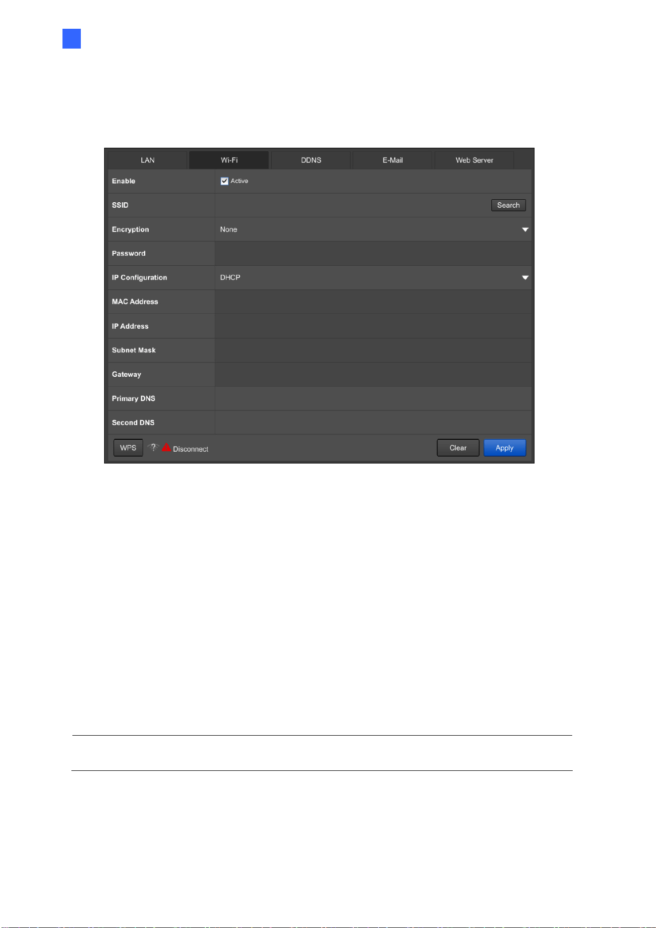
3.3.2 WiFi
Note this function is only applicable to GV-SNVR0411 / 0811.
Figure 3-10
Before using the WiFi function, make sure to insert a GV-WiFi Adapter.
To enable WiFi, click Active.
SSID: Click Search to detect WiFi networks within the range of GV-SNVR.
Encryption: Select the type of encryption of the selected network.
Password: Type the login password for the network selected.
IP Configuration: Select DHCP for the network to assign an IP address for the WiFi
adapter, or select Static to type the IP information, including IP address, Subnet Mask,
Gateway and/or Primary and Secondary DNS.
WPS: Alternatively, you can connect GV-SNVR to your router through WPS. To do this,
enable WPS on your router, click the WPS button and type the required information.
IMPORTANT: Do not set the WiFi Subnet to be the same as the LAN, or it will result in a
conflict of the system’s network.
77
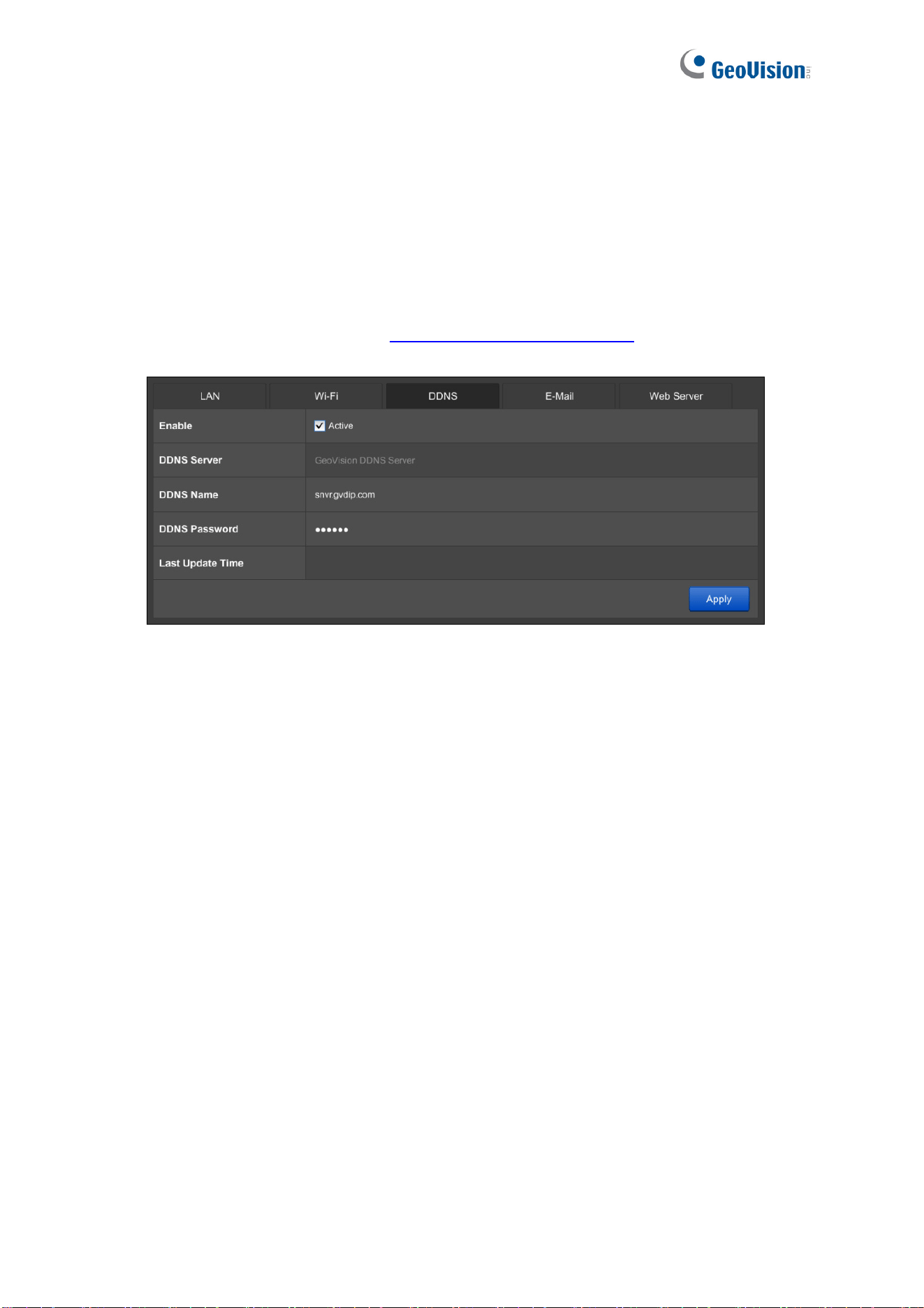
3.3.3 DDNS
DDNS (Dynamic Domain Name System) provides a convenient way of accessing GV-SNVR
when using a dynamic IP address. DDNS assigns a domain name to GV-SNVR, so you do
not need to go through the trouble of checking if the IP address assigned by DHCP Server
or ISP (in xDSL connection) has changed. Before enabling the following DDNS function, you
should have applied for a Host Name from the DDNS service provider’s website. The
provider is GeoVision DDNS Server:
http://ns.gvdip.com/register.aspx
.
Figure 3-11
To enable the DDNS function, click Active, type the Name and Password you have
registered with GeoVision DDNS Server and click Apply.
System Configuration
78
3
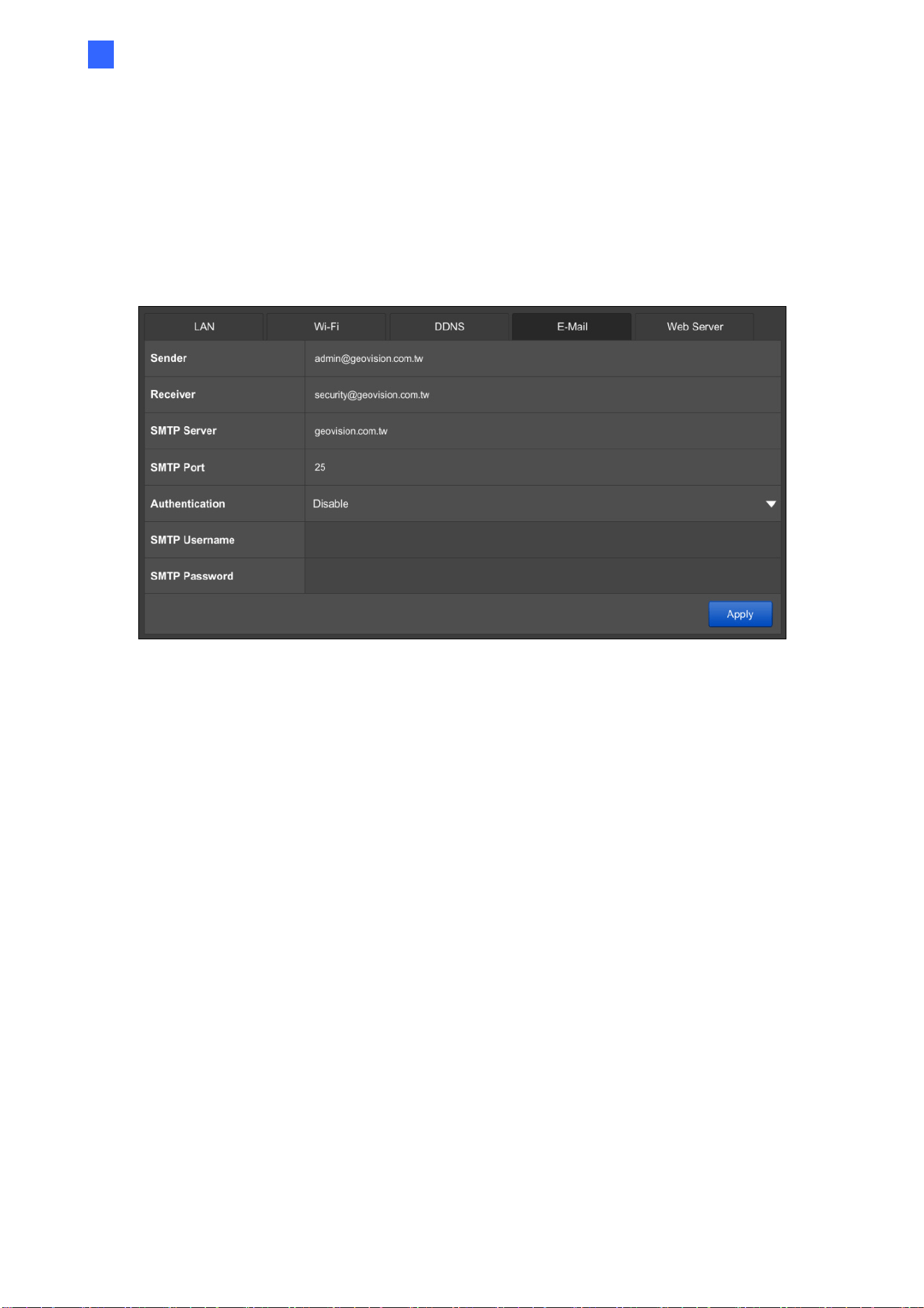
3.3.4 E-Mail
Configure your mail server to allow e-mail notifications upon:
- Error of writing recording data to the hard disk drive
- Request for the retrieval of username and password for system login
Figure 3-12
Sender: Type the sender’s e-mail address.
Receiver: Type the recipients’ e-mail address.
SMTP Sever: Type the mail server’s URL or IP address.
SMTP Port: Type the mail server’s port value.
Authentication: Select Enable if the SMTP Server requires authentication, and type a
valid username and password to log in the SMTP server in the next two columns.
Select Enable SSL if the e-mail server requires SSL authentication for connection.
Click Apply to save the e-mail settings.
79
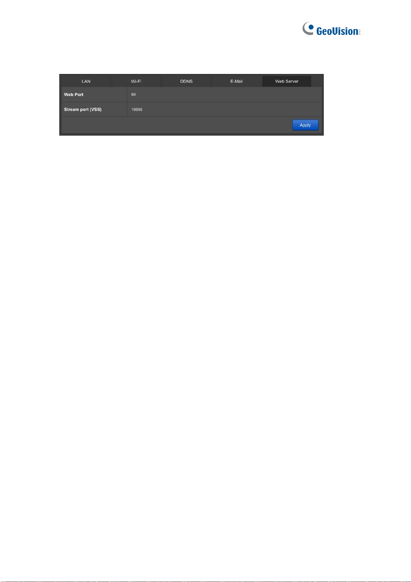
3.3.5 Web Server
Figure 3-13
Web Port: The Web Port is used for connection with compatible GeoVision software
and allows users to access GV-SNVR through the Web interface. The default port is 80.
Streaming port (VSS): The VSS streaming port is used for connection with GV-Eye
mobile app and compatible GeoVision software. The default port is 10000.
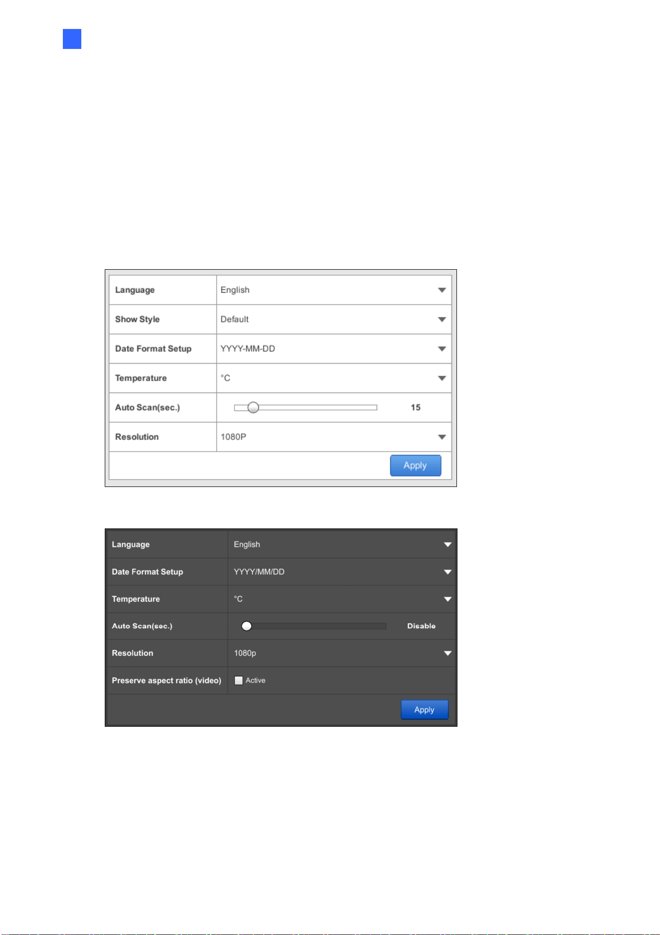
System Configuration
80
3
3.4 Storage
You must format the hard drive before enabling video recording. For details, see 2.4
Formatting Hard Drive.
3.5 Display
You can adjust how you want GV-SNVR to be displayed.
GV-SNVR0400F / 1600
GV-SNVR0411 / 0412 / 0811 / 0812 / 1611 / 1612
Figure 3-14
Language: Select a language for the OSD interface.
Show Style: Only for GV-SNVR0400F / 1600. Select a color scheme for GV-SNVR
interface. Default scheme is black.
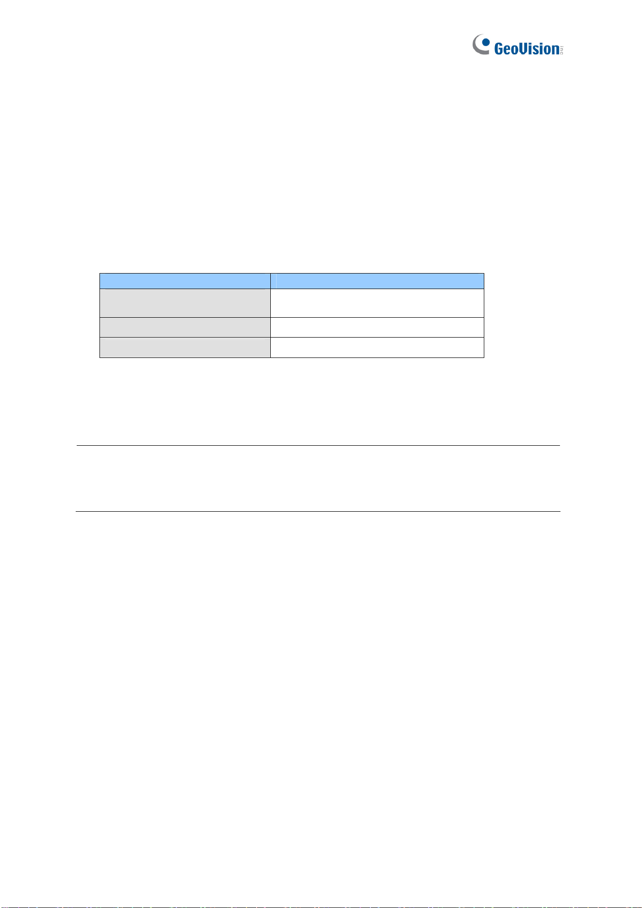
81
Date Format Setup: Select a display format for the date.
Temperature: Select to display the operating temperature in Celsius or Fahrenheit.
Auto Scan (sec.): Set a scan interval in seconds to enable the Auto Scan function. If
the number of cameras added exceeds the number of live view grids available, the
cameras will be shown in sequence for the selected time interval. In the example of a
15-second scan interval with 16 cameras in 9-ch division, GV-SNVR will alternate
between 15 seconds of showing cameras 1 - 9 and another 15 seconds for cameras 10
- 16.
Resolution: Select the video output resolution.
Model Video Output
GV-SNVR0411 / 0412 / 0811
/ 0812 / 1611 / 1612
1080p, 4K
GV-SNVR0400F
720p, 1080p, 1080i
GV-SNVR1600
1080p
Preserve Aspect Ratio (Video): Only for GV-SNVR0411 / 0412 / 0811 / 0812 / 1611 /
1612. Click Active to preserve the aspect ratio of your camera. Once applied, restart
GV-SNVR for the change to take effect.
IMPORTANT: For GV-SNVR0411 / 0412 / 0811 / 0812 / 1611 / 1612, when you configure
the channel resolution to 4K, be sure your monitor is a 4K-capable monitor; otherwise
flickering / no image will be displayed on the screen. If it occurs, load factory default, and
the resolution will be reset to 1080p.
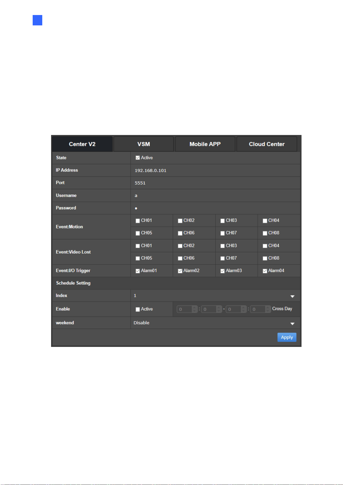
System Configuration
82
3
3.6 Service
3.6.1 Connecting to GV-Center V2 and GV-Vital Sign Monitor
In the Service settings, you can connect GV-SNVR to central monitoring station software
GV-Center V2 and GV-Vital Sign Monitor (VSM).
1. Click Active to enable connection with GV-Center V2 or GV-Vital Sign Monitor (VSM).
Figure 3-15
2. Type the IP Address or the domain name of GV-Center V2 or GV-Vital Sign Monitor.
3. Modify the Port if needed.
4. Type the Username and Password of GV-Center V2 or GV-Vital Sign Monitor.
5. Only for GV-SNVR0411 / 0412 / 0811 / 0812 / 1600 / 1611 / 1612, select camera
channels for Motion and Video Lost events alert. When either of these events occurs
on the selected cameras, GV-SNVR will send notifications or videos to GV-Center V2 or
GV-Vital Sign Monitor.

83
6. Only for GV-SNVR0412 / 0812 / 1611 / 1612 under the Center V2 tab,
˙ Select the desired input alarms. GV-SNVR will send notifications to GV-Center V2
upon the input triggers.
˙ In Schedule Setting, configure the schedules for sending notifications to GV-
Center V2. You can configure up to 3 schedules by selecting a Index and then
defining a period of time for weekdays or for weekend.
7. Click Apply. A green icon will appear if the connection is established successfully.
Note:
1. For compatible versions of GV-Center V2 and GV-Vital Sign Monitor, see 1.4.2
Supported GeoVision Applications for details.
2. For GV-Center V2, the audio function of live view is only supported in Single Live
View Window, and the IP device must be connected through stream 1.
3. For GV-Vital Sign Monitor, the Video Log Storage function is not supported when
viewing subscriber status.
3.6.2 Regulating People Flow with GV-IP Cameras
For GV-SNVR0412 / 0812 with firmware version V1.05 / V1.10 or later only, by integrating
GV-TDR2700 series, of firmware version V1.03 or later, the PPL tab on the Service page
can monitor the total people count at a vicinity and trigger output alarms and/or send out e-
mail alerts accordingly when the predefined limit is reached for effective people flow control.
See
here
for the detailed setup and related settings.
System Configuration
84
3
3.6.3 Connecting to GV-Eye
You can connect GV-SNVR to the mobile app GV-Eye using the QR-code scan.
Note:
1. For the compatible version of GV-Eye with your GV-SNVR, see 1.4.2 Supported
GeoVision Applications.
2. To use this function, GV-SNVR must be connected to the Internet.
3. Up to 2 GV-Eye / Remote ViewLog / SNVR Viewer can be connected to a GV-SNVR
at a time.
Click Mobile APP. This interface appears. To connect GV-Eye to GV-SNVR using the QR-
code scan, refer to 5. GV-Relay QR Code in
GV-Eye Installation Guide
.
Figure 3-16
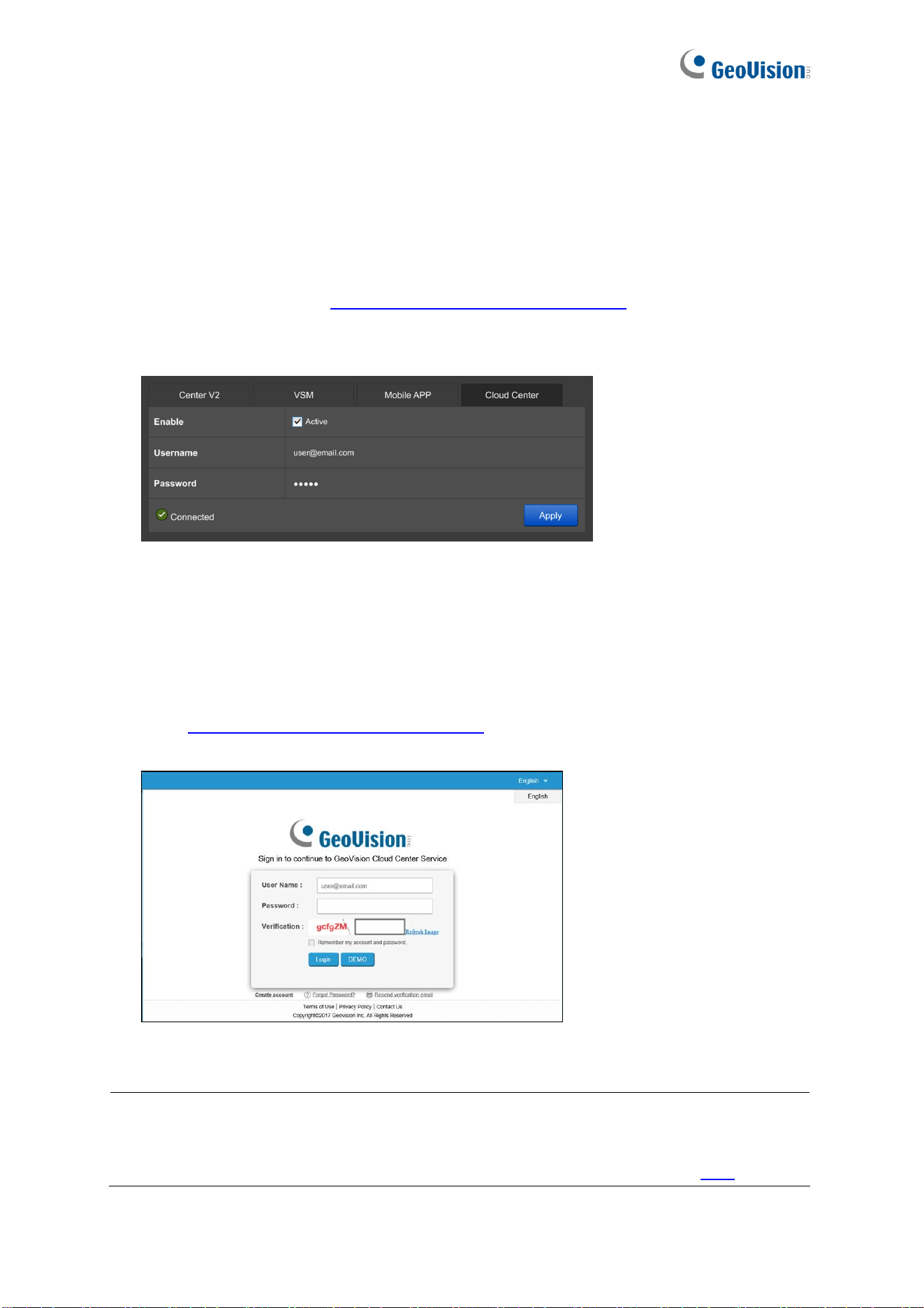
85
3.6.4 Connecting to GV-Cloud Center
Note this function is only applicable to GV-SNVR0411 / 0412 / 0811 / 1611 / 1612 and GV-
SNVR0812 V1.05 or later.
You can connect GV-SNVR to the cloud-based software GV-Cloud Center using the Cloud
Center account registered at
https://dashboard.vsm.mygvcloud.com/
.
1. Click Cloud Center. This interface appears.
Figure 3-17
2. Select Active to enable.
3. Type the Username and Password of your Cloud Center account.
4. Click Apply. A green icon will appear if the connection is established successfully.
5. Go to
https://dashboard.vsm.mygvcloud.com/
and fill in the required information to view
GV-SNVR on GV-Cloud Center.
Figure 3-18
Note:
1. To use this function, GV-SNVR must be connected to the Internet.
2. Only the system log of GV-SNVR is accessible through GV-Cloud Center. See
System Log in 3.8 System and refer to GV-Cloud Center User’s Manual here
.
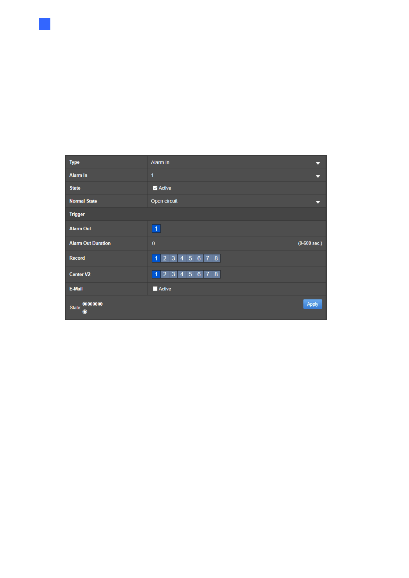
System Configuration
86
3
3.7 Event
Note this function is only applicable to GV-SNVR0412 / 0812 / 1611 / 1612.
In the Event settings, you can configure GV-SNVR to trigger output alarms, start video
recording, send e-mail alerts and/or trigger buzzer upon motion detection and input trigger
events.
Figure 3-19
Type: Select the type of event you wish to configure, between Alarm In or Motion.
Alarm In: When the type of event is selected, select the desired input module from
1 ~ 4.
Motion: When the type of event is selected, select the desired camera channel
from 1 ~ 4 / 1 ~ 8 / 1 ~ 16 respectively for GV-SNVR0412 / 0812 / 1611 / 1612.
State: When Alarm In is selected, select Active to enable the input module.
Normal State: When Alarm In is selected, select between Open circuit or Closed
circuit to define the module as normally open or normally closed, respectively.
People counter: For GV-SNVR0412 / 0812 with firmware version V1.05 / 1.10 or
later only, see 3.6.2 Regulating People Flow with GV-IP Cameras.
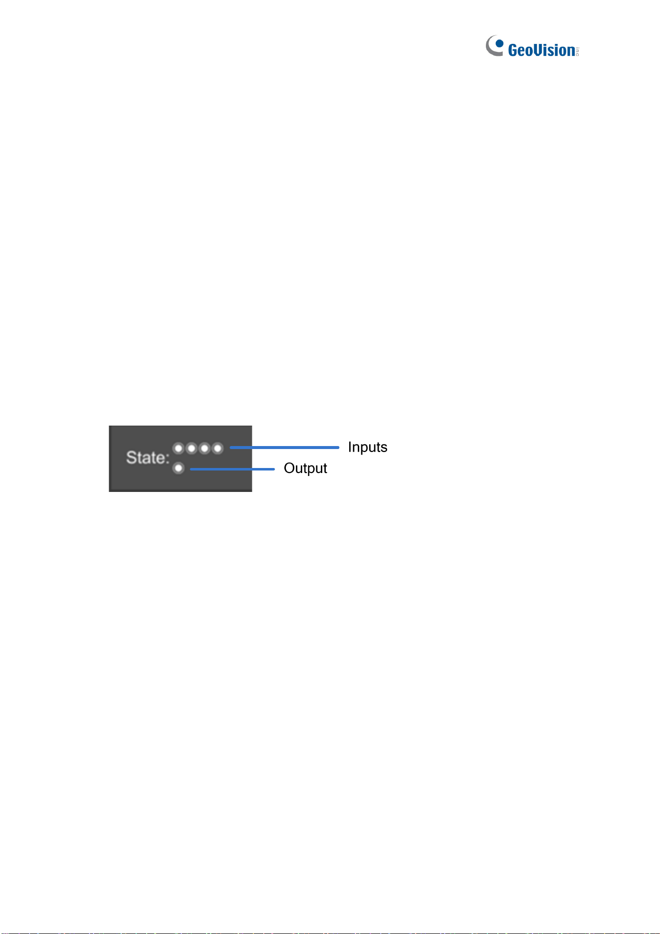
87
[Trigger]
Alarm Out: Select the output to be triggered upon input trigger or motion detection
events.
Alarm Out Duration: Specify the duration for the output to be triggered, from 0 to 600
seconds.
Record: Select the desired camera channel(s) to start recording upon input trigger or
motion detection.
Center V2: Select the desired camera channel(s) to start recording upon input trigger
or motion detection.
E-Mail: Select Active to send e-mail alerts upon input trigger or motion detection. To
set up the e-mail server, see 3.3.4 E-Mail.
Buzzer: Only for GV-SNVR1611 / 1612, select Active to sound the buzzer on GV-
SNVR upon input trigger or motion detection.
State: The icons indicate the status of the 4 inputs and 1 output by turning red upon
trigger.
Figure 3-20
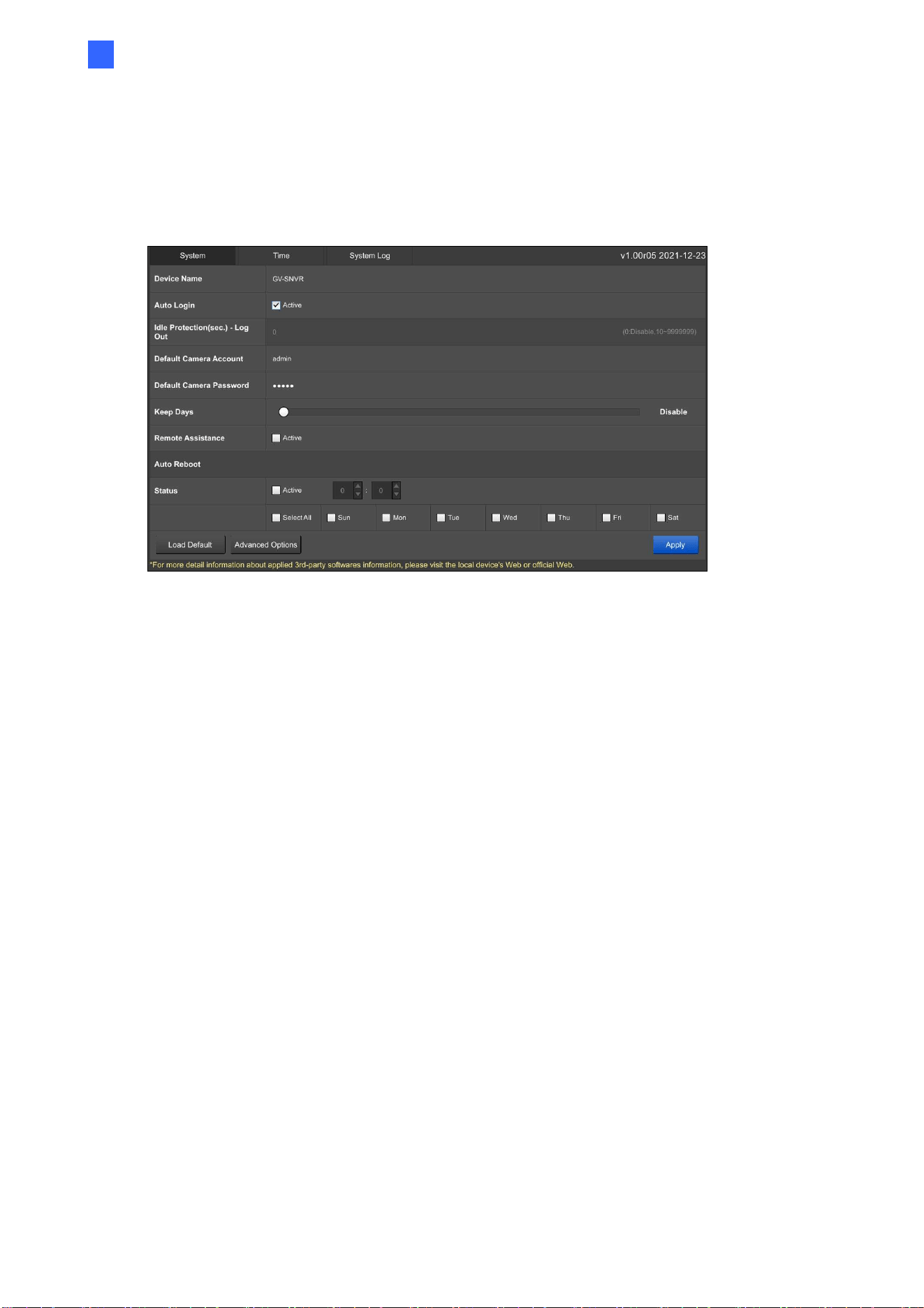
System Configuration
88
3
3.8 System
In the System settings, you can change the device name and login information of GV-SNVR.
You can also access the Time settings and System Log.
Figure 3-21
Device Name: Name GV-SNVR.
Auto Login: Select Active to enable the automatic login for GV-SNVR (only applicable
to GV-SNVR1612).
Idle Protection (sec.)-Log Out: When Auto Login is disabled, set the desired idle
time from 1 to 9999999 seconds for an automatic logout when GV-SNVR is not under
operation. When the value is set as 0, the function is disabled even when Auto Login
is disabled (only applicable to GV-SNVR1612).
Default Camera Account: Set up the default username for cameras connecting to GV-
SNVR. The default is admin.
Default Camera Password: Set up the default password for cameras connecting to
GV-SNVR. The default is admin.
Keep Days: Only for GV-SNVR0411 / 0412 / 0811 / 0812 / 1600 / 1611 / 1612, drag the
slider to specify from 1 to 31 days to keep video files in storage.
Auto Reboot: Only for GV-SNVR0412 / 0812 / 1612, select Active, and define the day
and time to automatically restart the device.
Load Default: Restore GV-SNVR to its default settings. Alternatively, press the Load
Default button on the device for 15 seconds.
Advanced Options: Import / export system settings or upgrade firmware. Alternatively,
you can also access the 3 options through GV-IP Device Utility. For details, see 6.1
Advanced Options and 6.2 Using GV-IP Device Utility.
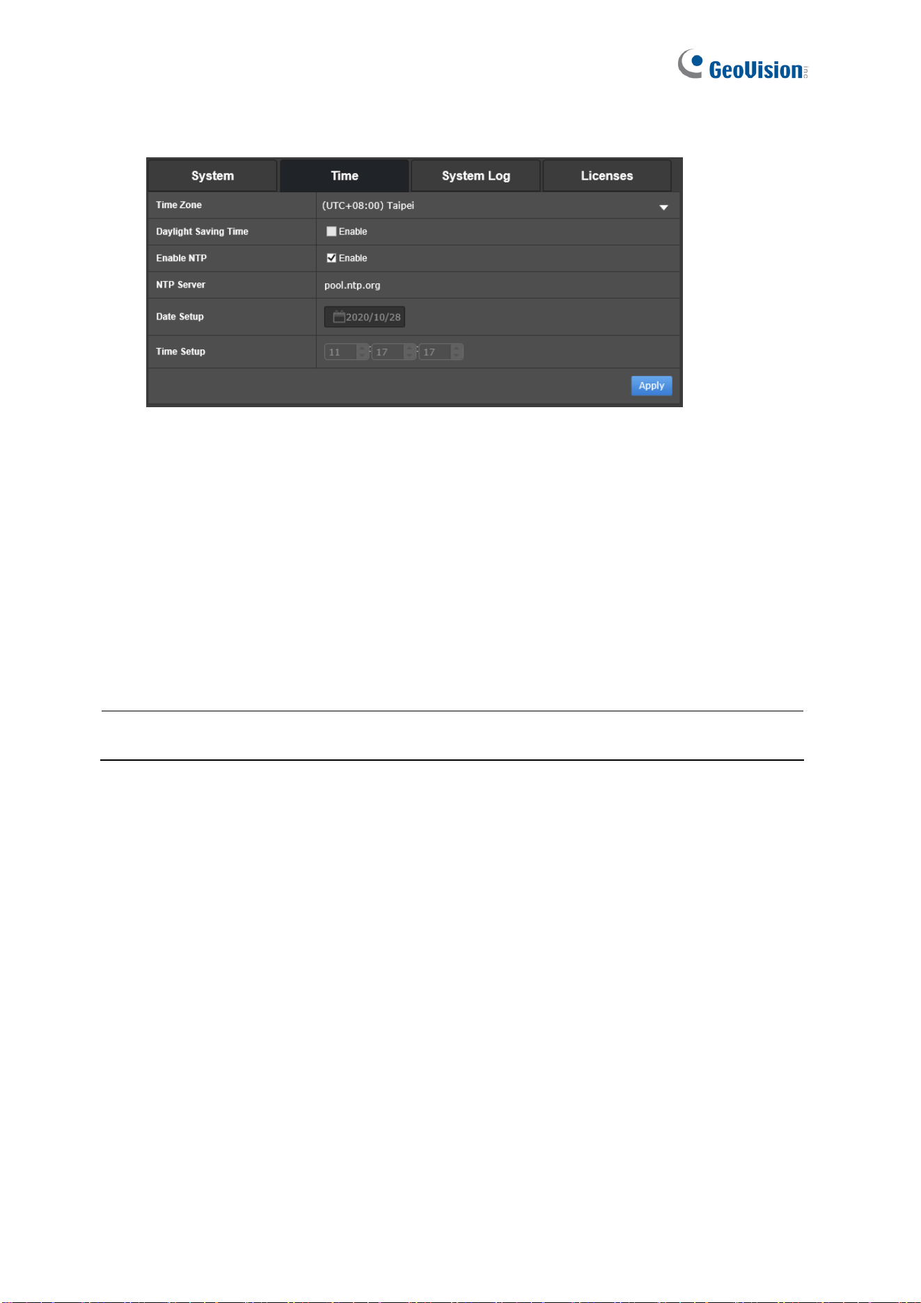
89
[Time]
Figure 3-22
Time Zone: Select the time zone of your location.
Daylight Saving Time: Click Enable / Active and type the start time and end time for
the system to automatically adjust to Daylight Saving Time.
Enable NTP: Enable the NTP server and type the URL of a network time server to
synchronize the time of GV-SNVR accordingly. Otherwise, manually set up the date
and time by filling out the corresponding fields.
To enable the adjusted settings, click Apply.
Note: You can also use GV-IP Device Utility to synchronize the date and time of GV-SNVR
with a computer. For details, see GV-IP Device Utility Installation Guide
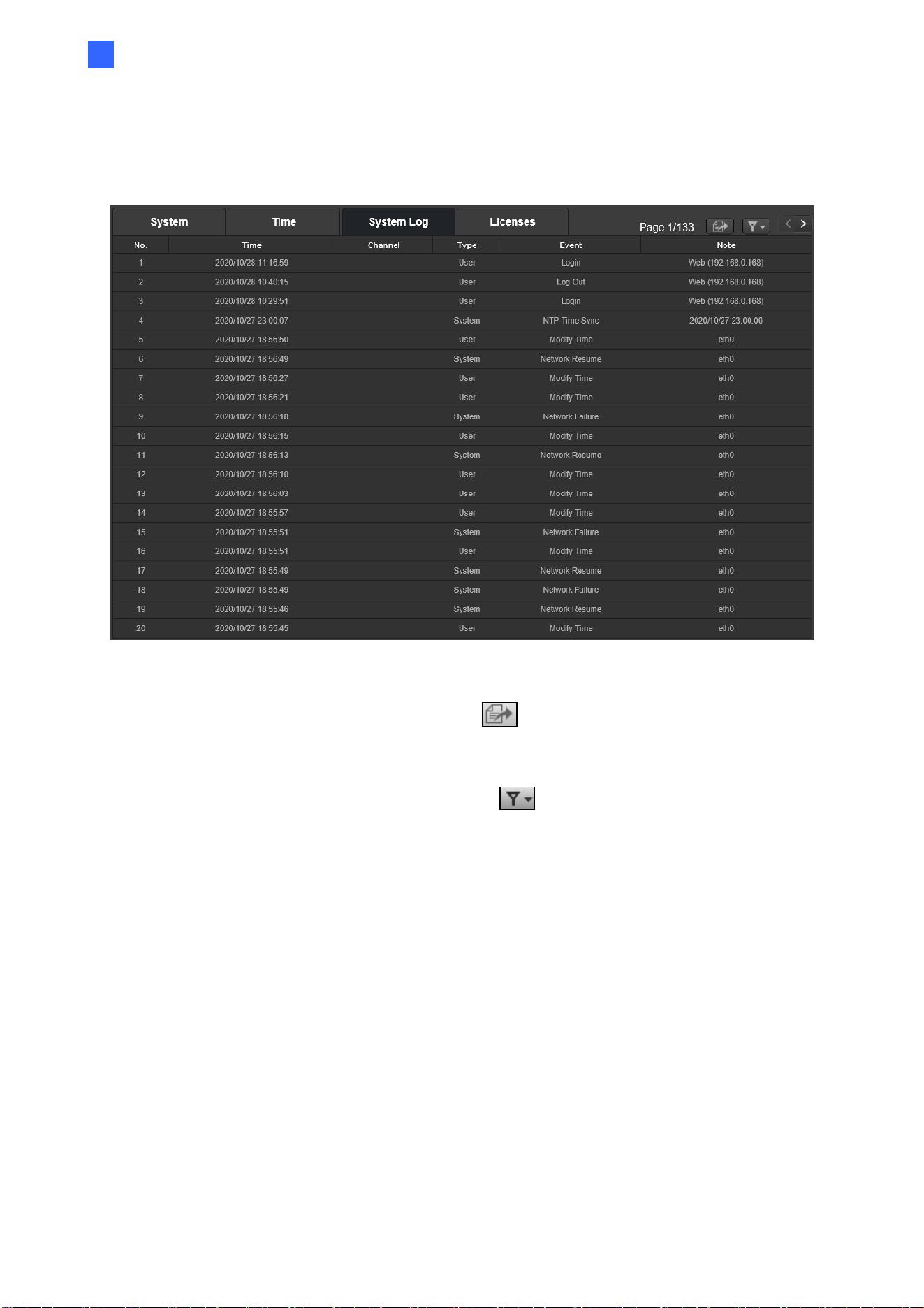
System Configuration
90
3
[System Log]
This page lists all the changes made to the system.
Figure 3-23
To export the system log, click the Export button
at the upper-right corner and click
Apply. A USB flash drive needs to be inserted to GV-SNVR prior to exporting.
To search for specific events, click the Filter button
at the upper-right corner to limit the
search results using the following options.
Start / End Time: Set up the desired time period.
Channel: Select a channel.
Type: Select User or System.
Event: Select a type of event.
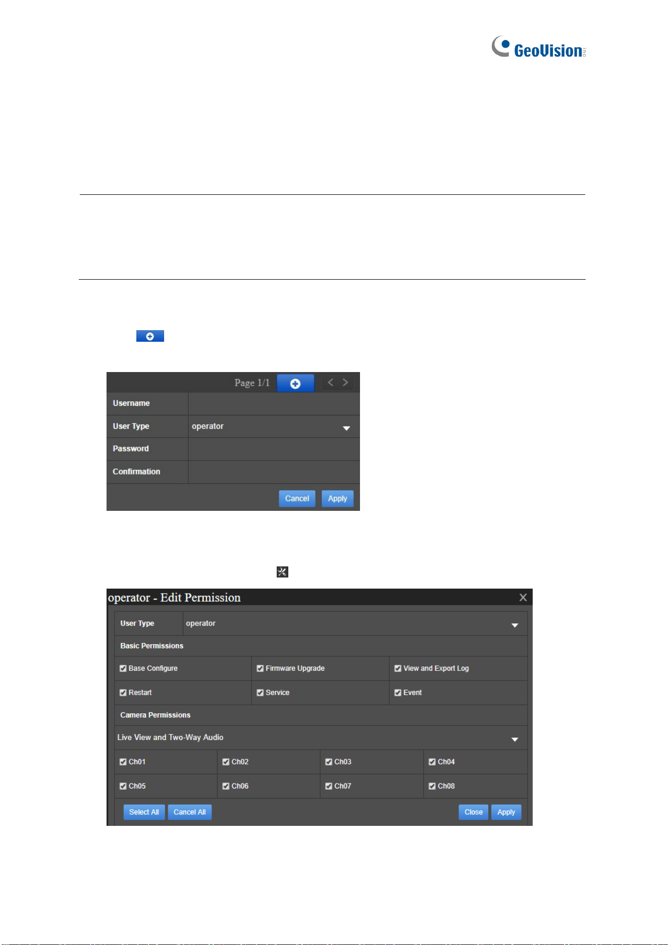
91
3.9 Account
In the Account settings, you can manage up to 10 system users, including admin, operator,
and guest, and grant different permissions to operators.
Note:
1. The Admin account has full access to the functions of GV-SNVR. Make sure to use
the Admin account of GV-SNVR when being connected from GeoVision software, e.g.
GV-Edge Recording Manager.
2. The Guest account only has access to the live view and playback of GV-SNVR.
Adding an operator
1. Click
. Select the desired User Type and type the necessary information for
Username, Password, and Confirmation.
Figure 3-24
2. Click Apply to finish adding the new account.
3. To configure permissions, click
of the desired account. This page appears.
Figure 3-25
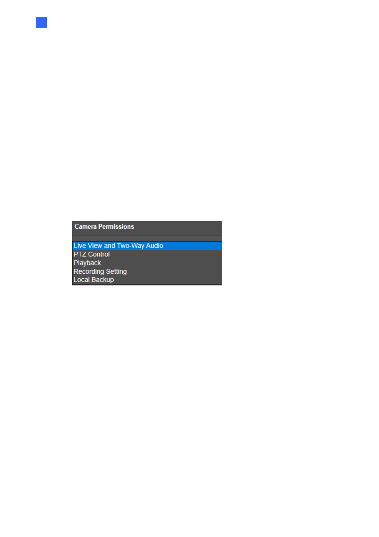
System Configuration
92
3
4. On the Edit Permission page, you can configure the User Type, Basic Permissions
and Camera Permissions of the selected account.
User Type: You can change Operator to Guest which only has access to live view
and playback functions.
Basic Permissions: Configure the permissions you wish to grant or deny access to.
Base Configure: Access to Network and System settings.
Firmware Upgrade: Access to Firmware Upgrade in System settings.
View and Export Log: Access to System Log in System settings.
Restart: Access to Reboot. See details in 2.5 Main Screen.
Service: Access to Service settings.
Event: Access to Event settings.
Camera Permissions: Select through each option in the drop-down list and
configure specific channels you wish to grant or deny access to.
Figure 3-26
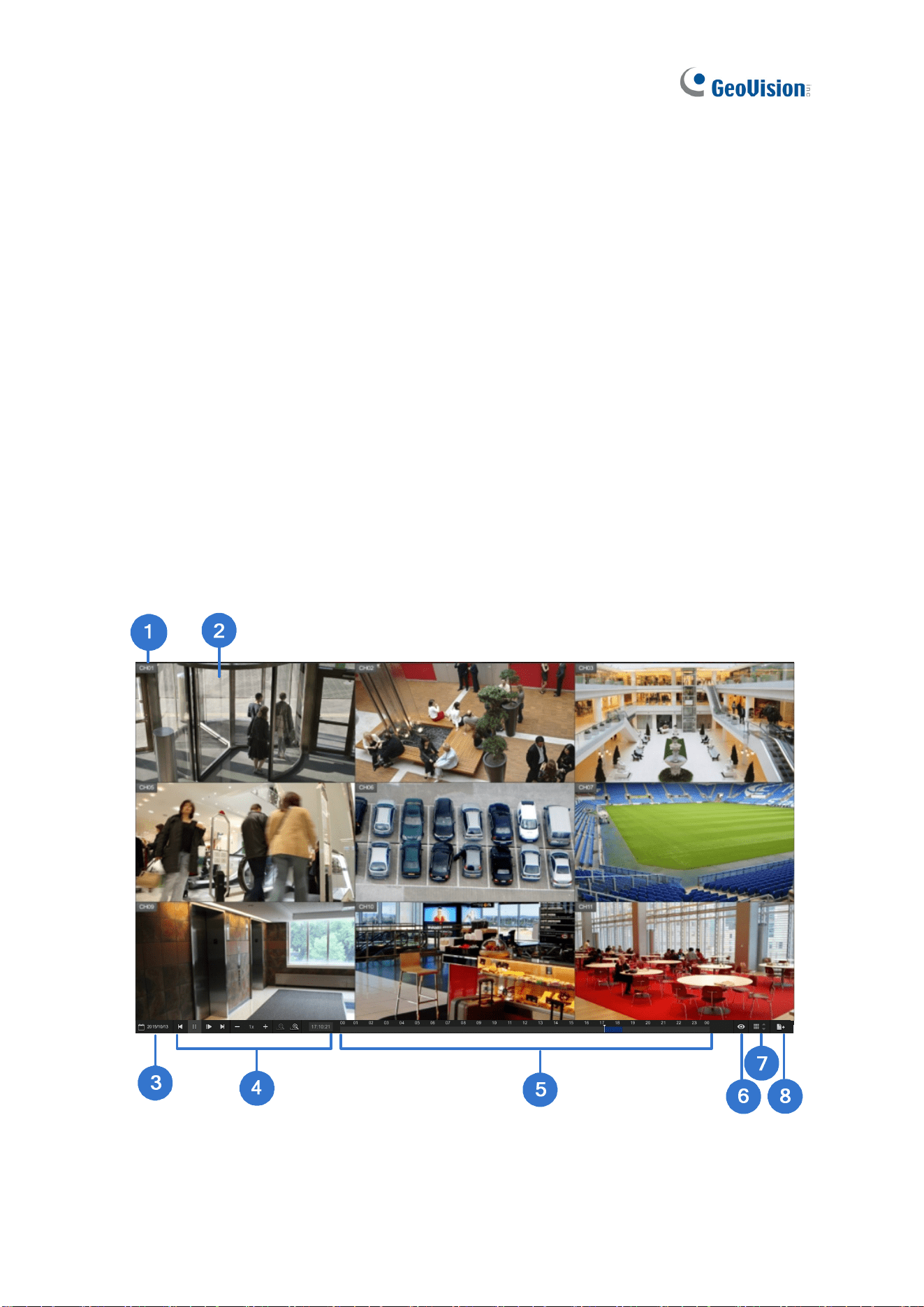
93
Chapter 4 Video Playback
The timeline player plays back recorded video without affecting recording. There are two
ways to launch the timeline player:
˙ On the main screen, click the Playback button (No. 6, Figure 2-28).
˙ On the camera view, click a camera name and select Instant Playback.
On the timeline player screen, the system automatically plays back video recorded from 3
minutes before the playback function is enabled.
4.1 Timeline Player
Without further settings, you can play back video by selecting a time and clicking the Play
button on Playback Panel. To switch the view mode, click the Division button. Here we use
GV-SNVR0811 for illustration.
Figure 4-1
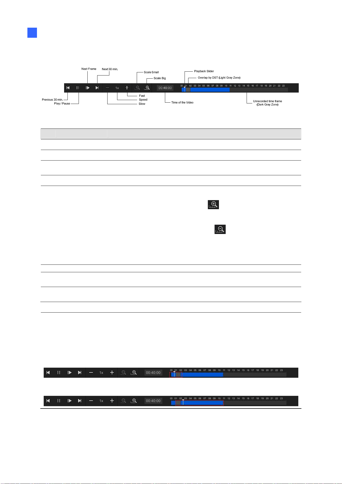
Video Playback
94
4
Use controls on the Playback Panel to view the event in the way you want. Move the slider
forward or backward to navigate through video frames.
Figure 4-2
The controls in the timeline player screen:
No. Name Description
1 Camera Name Indicates the camera name.
2 Camera View Displays the playback video.
3 Date Display
Allows you to specify a date for playback. The date with recordings
is highlighted in blue.
4 Playback Panel Contains typical playback control buttons.
5 Timeline
The time with recordings is highlighted in blue.
For GV-SNVR0411 / 0412 / 0811 / 0812 / 1600 / 1611 / 1612,
a) With the Scale Big button
clicked, displays a 60-
minute timeline consisting of 12 grids with each specifying
five minutes.
b) With the Scale Small button
clicked, displays a 24-
hour timeline consisting of 24 grids with each specifying an
hour.
For GV-SNVR0400F, displays a 24-hour timeline consisting of
48 grids, with each specifying half an hour.
6 Live Closes the timeline player and returns to the live view window.
7 Division
Changes the screen division, which varies among different GV-
SNVR models.
8 Export
Exports recordings as AVI files to a USB flash drive.
See 4.2
Recording Export for details.
Note:
The light gray zone in between the blue recording zones, as indicated in Figure 4-2, is a
one-hour overlap of 2 separate recordings caused by the Daylight Saving Time (DST).
Note the following to distinguish the recordings.
To play back the last hour of the recording with DST enabled, click the Next 30 min.
button when the Playback Slider is placed before the gray zone.
To play back the first hour of the recording with DST disabled, click the Previous 30
min. button when the Playback Slider is placed after the gray zone.
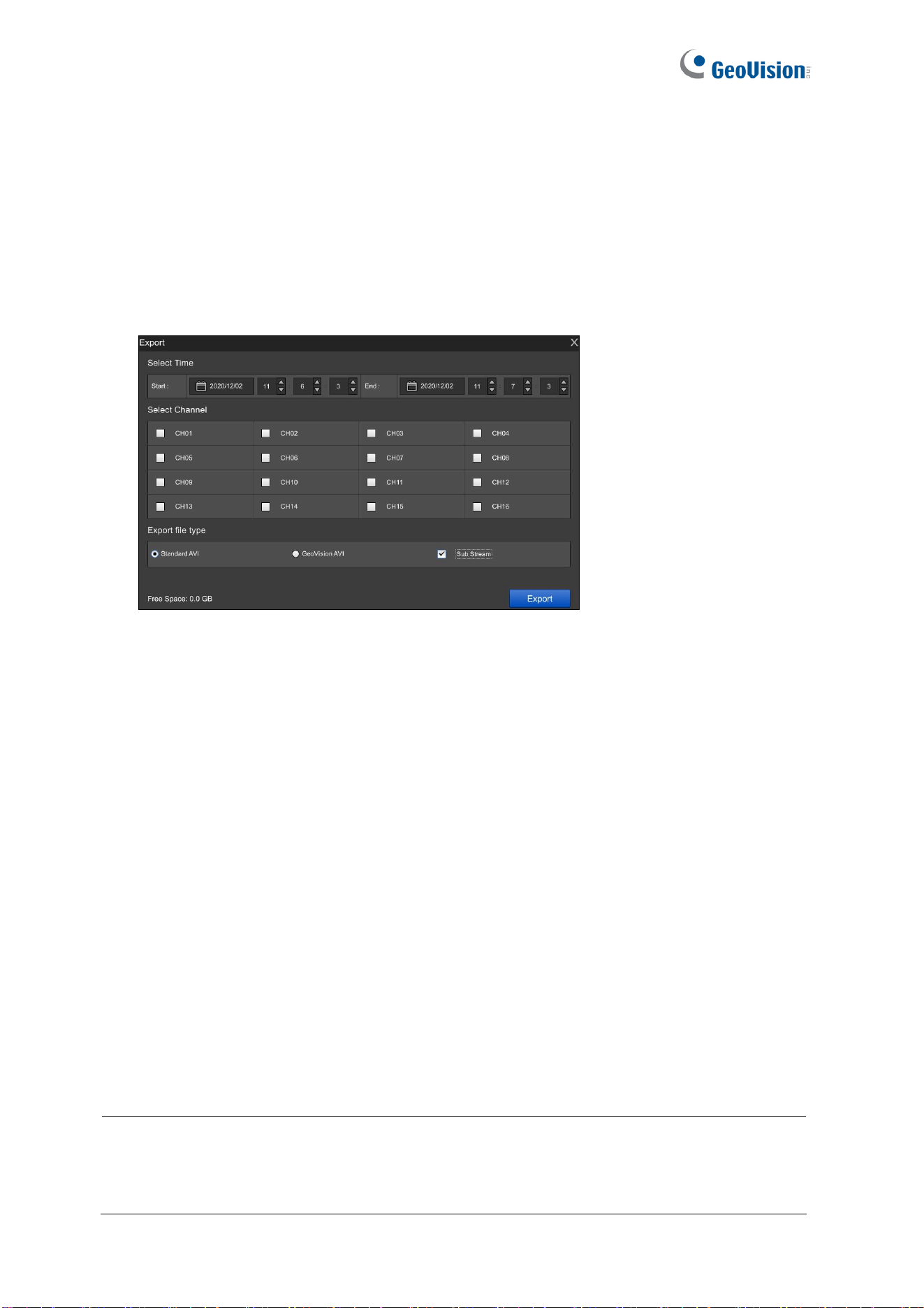
95
4.2 Recording Export
Using the timeline player, you can export recordings to a USB flash drive. To export
recordings, follow the steps below.
1. Connect a USB flash drive of FAT32 format to the USB port on the device.
2. On the timeline player screen, click Export (No.8, Figure 4-1).
Figure 4-3
For GV-SNVR0411 / 0412 / 0811 / 0812 / 1611 / 1612:
˙ Select GeoVision AVI to export video without audio.
˙ Select Standard AVI to export video with audio. Note the Standard AVI file is not
supported by GeoVison applications.
˙ Only for GV-SNVR1611 / 1612, select Sub Stream to export sub-stream recordings
if the camera host is recorded in dual streams.
For GV-SNVR0400F / 1600, the recordings are exported in GeoVision AVI format.
3. Select the start and end time of the recordings to be exported.
4. Select the desired channels for export.
5. Click Export.
For the recordings exported in GeoVision AVI or Standard AVI format, you need to install
GeoVision codec in a PC for playback using Windows Media Player. For GeoVision AVI
format only, you can install the GV-ViewLog player for playback.
Note:
1. For GV-SNVR0400F / 1600, the exported recordings only support video.
2. If GV-SNVR is connected with more than one USB flash drive, the recordings will be
backed up to the first USB flash drive connected.

96
Chapter 5 Remote Access to GV-SNVR
Users can remotely access GV-SNVR through the following methods:
⚫ Web browser for IE users only
⚫ SNVR Viewer
⚫ GV-Eye mobile app
⚫ GV-Edge Recording Manager
⚫ GV-Control Center
⚫ RTSP
For a comparison of functions provided by different remote accesses, see the
table.
Note:
1. For supported Web browsers and compatible GeoVision applicaitions, see 1.4
Compatible Products and System Requirements for details.
2. The maximum number of remote connection is 10 in total for GV-SNVR0411 / 0400F /
0412, 18 in total for GV-SNVR0811 / 0812, 34 in total for GV-SNVR1600 / 1612 and
51 in total for GV-SNVR1611. Every connected channel will be counted as 1
connection.
3. GV-Edge Recording Manager / GV-Control Center can remotely play back recordings
stored on GV-SNVR. GV-SNVR1611 supports remote playback from 2 GV-Edge
Recording Manager / GV-Control Center at a time, while GV-SNVR0411 / 0412 / 0811
/ 0812 / 1612 only supports 1 at a time.
4. Up to 2 mobile applications (GV-Eye) and/or PC-based software (e.g. Remote
ViewLog / SNVR Viewer) can be connected to a GV-SNVR for live view at a time.
5. Up to 1 mobile application (GV-Eye) or PC-based software (e. g. Remote
ViewLog / SNVR Viewer) can be connected to a GV-SNVR for remote playback at a
time.
6. For SNVR0412 V1.04 and SNVR0812 V1.09, or later versions, if you want to create
an account through Web browser or SNVR Viewer, the password of the account must
contain at least 6 characters and 4 character categories among the following:
uppercase letters, lowercase letters, digits and special characters. While creating an
account on the device, the password only requires 3 character categories.
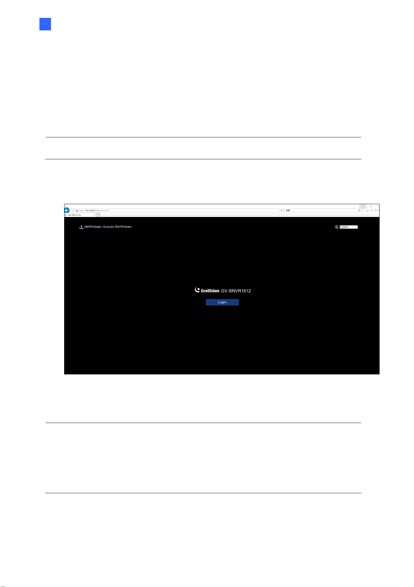
Accessing through Web Browser
97
5
5.1 Accessing through Web Browser
To access live view through a Web browser, follow the steps below.
1. Open your Web browser and type the IP address of GV-SNVR.
Note: To look up the IP address of GV-SNVR, see 3.3 Network. Alternatively, run GV-IP
Device Utility to search for your GV-SNVR. For details, see 6.2 Using GV-IP Device Utility.
2. Select a desired language from the drop-down list at the upper-right corner of the Web
interface and click Login.
Figure 5-1
3. Type your username and password on the pop-up window and click OK.
Note:
1. To enable the update of live view on your Web browser, you must set the Web
browser to allow ActiveX controls and perform a one-time installation of GeoVision’s
ActiveX components on your computer.
2.
For users of Mozilla Firefox, Google Chrome, Safari and Microsoft Edge, it is required to
download SNVR Viewer for remote access. For details, see 5.2 Accessing through SNVR
Viewer.
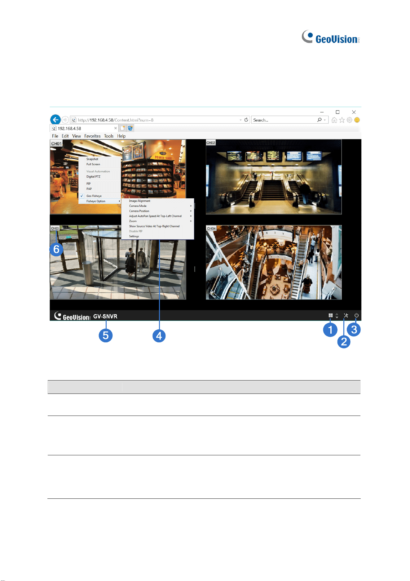
98
5.1.1 Live View Screen
After successfully logging in the Web interface, you can access the live view of connected IP
cameras.
Figure 5-2
No. Name Description
1
Division & Page
Up / Down
Select screen divisions and switch between cameras in single
division.
2 Setting
Access the following system configuration pages of GV-SNVR:
Camera, Record, Network, Storage, Service, Event, System, and
Account. See Chapter 3 System Configuration for details on these
settings.
Note:
1. For SNVR0400F / 1600, the System Log is not accessible via the Web interface.
2. Configurations of camera settings through the Web interface is only supported by GV-
SNVR0812 V1.05 or later, see 5.1.2 Camera Settings via Web.

Accessing through Web Browser
99
5
No. Name Description
3 Exit
Log out the Web interface.
4
Advanced
Options
Right-click the live view of desired camera to access the functions
below.
Snapshot: Take a snapshot of live video. For details, see 5.1.3
Snapshot of Live Video.
Full Screen: Switch the live view to full screen.
Resolution: Display the resolution at the lower-right corner of
the live view.
Digital PTZ: Simulate the PTZ movement on the screen. For
details, See 5.1.6 Digital PTZ Control.
PIP: Enable the PIP function. For details, See 5.1.4 Picture-in-
Picture View.
PAP: Enable the PAP function. For details, See 5.1.5 Picture-
and-Picture View.
Geo Fisheye: Only for GV-SNVR0411 / 0412 / 0811 / 0812 /
1611 / 1612, select to enable the fisheye settings. For details,
See 5.1.7
Fisheye View.
5 Device Name
Show the device name of GV-SNVR. See Device Name in 3.8
System.
6 Camera Name
Click the camera name to capture snapshots or enable speaker.
Note:
1. The Web interface of GV-SNVR only connects to the main stream of GV-IP Cameras
when using single division and 4-division display. For details, see Appendix B Live View
Streaming.
2. The Visual Automation function is not supported.
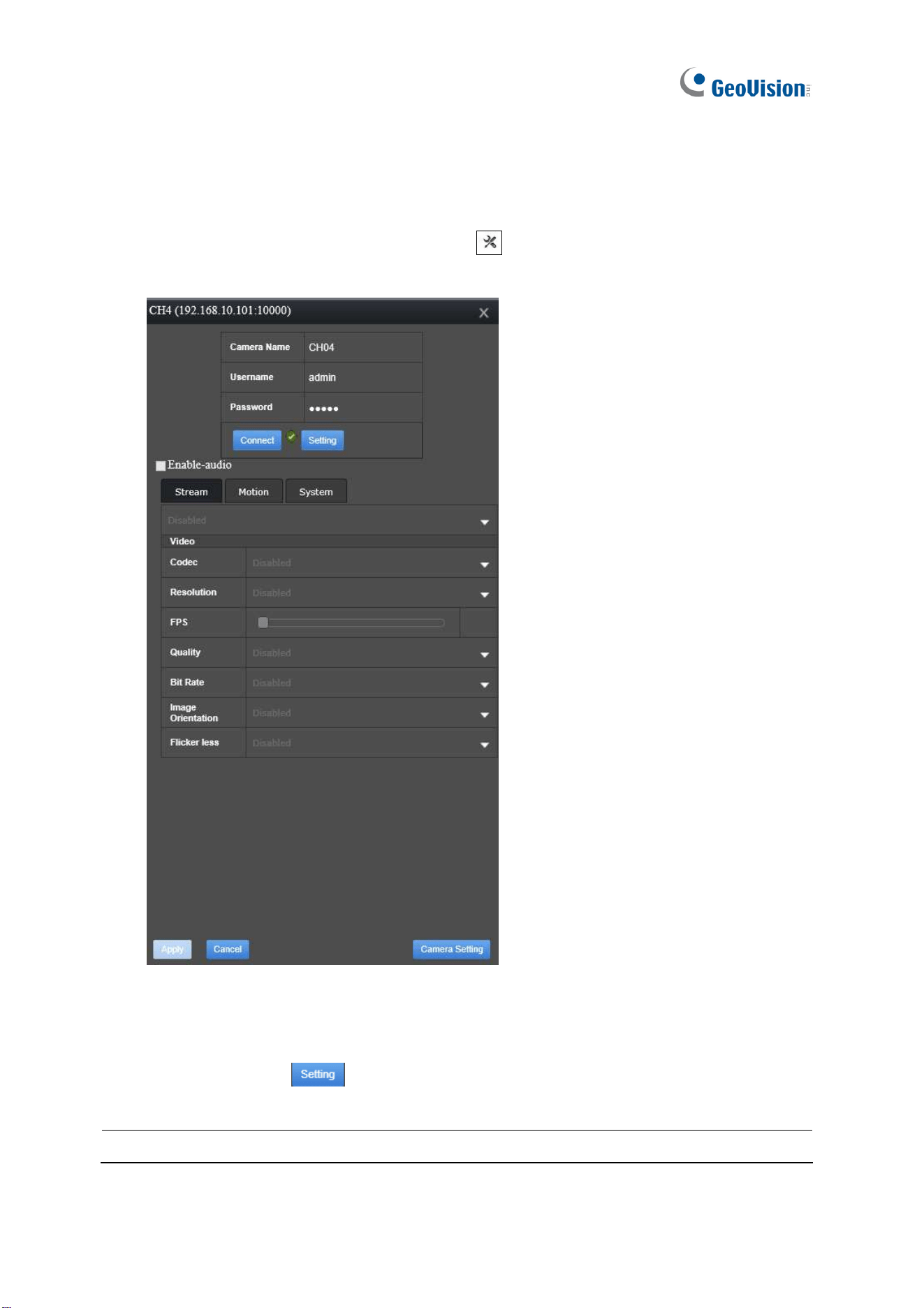
100
5.1.2 Camera Settings via Web
For GV-SNVR0812 V1.05 or later only, to configure the settings of cameras connected to
GV-SNVR via its Web interface, click the Setting button (No. 2, Figure 5-2) on the live view
screen, select Camera and click the Edit button
next to the desired camera. The
following dialog box appears.
Figure 5-3
All settings are first grayed out upon access. To configure camera settings, which are
detailed in 3.1.1 GV-IP Camera Settings and 3.1.2 Third-Party IP Camera Settings (ONVIF),
click the Setting button
Note: The Camera Setting button at the bottom-right corner is currently nonfunctional.
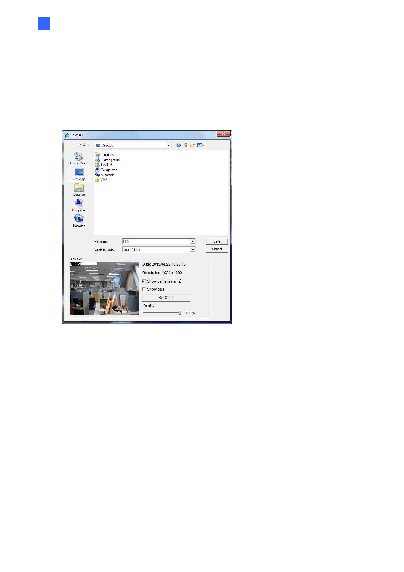
Accessing through Web Browser
101
5
5.1.3 Snapshots of Live Video
To take a snapshot of live video, follow the steps below.
1. Right-click on the live view of desired camera and select Snapshot. This dialog box
appears.
Figure 5-4
2. Select a storage path, name the file and select an image format from JPEG or BMP
under Save as Type.
3. In the Preview field, you can choose whether to tag the snapshot with camera name,
time and date, select Set Color for the text color and adjust the image quality.
4. Click Save to save the captured image.
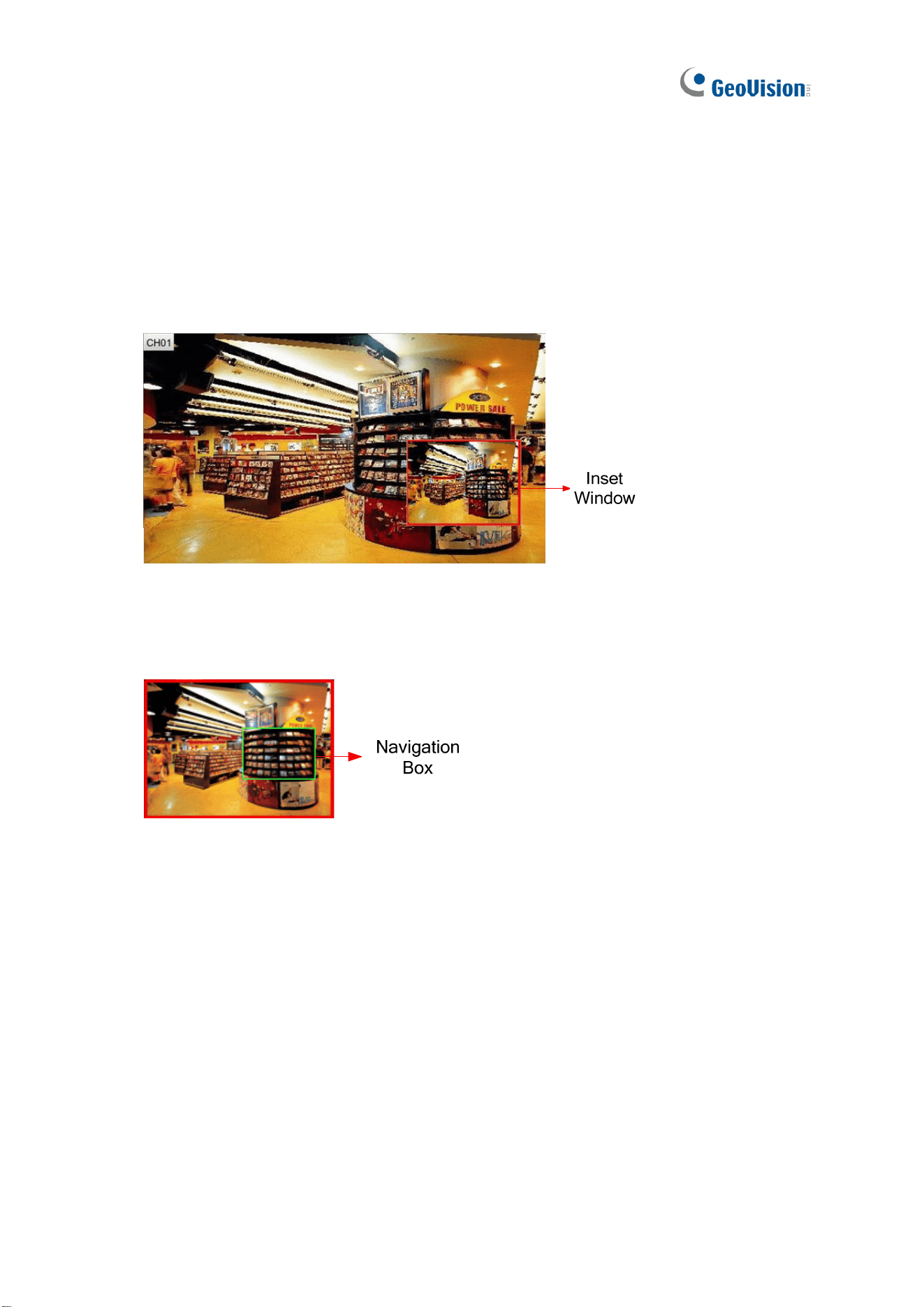
102
5.1.4 Picture-in-Picture View
With the Picture in Picture (PIP) view, you can crop the video to get a close-up view or zoom
in on the video. This function is useful for detailed images of the surveillance area.
1. Right click on the live view of a desired camera and select PIP. An inset window of the
camera view appears in the bottom right corner.
Figure 5-5
2. Double-click the inset window. A hand icon appears.
3. Click the inset window. A navigation box appears.
Figure 5-6
4. Move the navigation box around in the inset window to have a close-up view of the
selected area.
5. To adjust the navigation box size, move the cursor to any of the box corners to enlarge
or diminish the box.
6. To change the frame color of the navigation box, right click the image, select Mega Pixel
Setting and then Set Color of Focus Area.
7. To hide the navigation box on the image, right click the image, select Mega Pixel
Setting and click Hide Focus Area of PIP Mode
8. To exit the PIP view, right click the camera view and click PIP again.
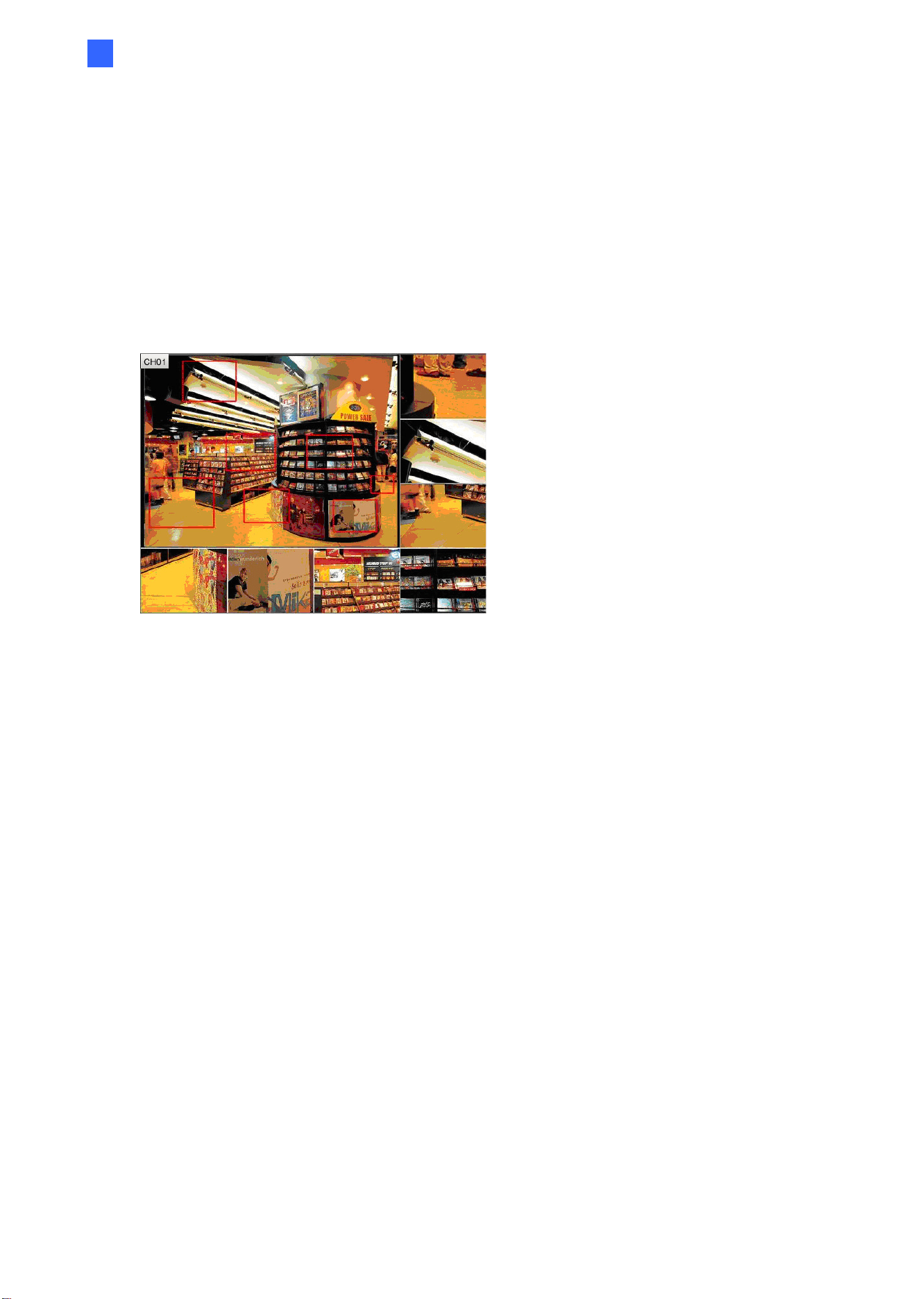
Accessing through Web Browser
103
5
5.1.5 Picture-and-Picture View
With the Picture and Picture (PAP) view, you can create a split video effect with multiple
close-up views on the image. Up to 7 close-up views can be defined for clear and detailed
images of the surveillance area.
1. Right click on the live view of a desired camera and select PAP. A row of three inset
windows appears on the bottom of the live view image.
Figure 5-7
2. Draw a navigation box by clicking and dragging on the image. This selected area is
immediately displayed in one of the inset windows. Up to seven navigation boxes can be
drawn on a live view image.
3. To adjust the size of a navigation box, move the cursor to any of the box corners to
enlarge or diminish the box.
4. To move a navigation box to another area on the image, drag it to that area.
5. To change the frame color of the navigation box, right click the image, select Mega
Pixel Setting and click Set Color of Focus Area.
6. To hide the navigation box on the image, right click the image, select Mega Pixel
Setting and click Display Focus Area of PAP Mode.
7. To delete a navigation box, right click the desired box, select Focus Area of PAP Mode
and select Delete.
8. To exit the PAP view, right click the live view and select PAP again.
9. To add another navigation box when less than seven navigation boxes are drawn, right
click the camera view, select Mega Pixel Setting and Enable Add-Focus-Area-Mode.
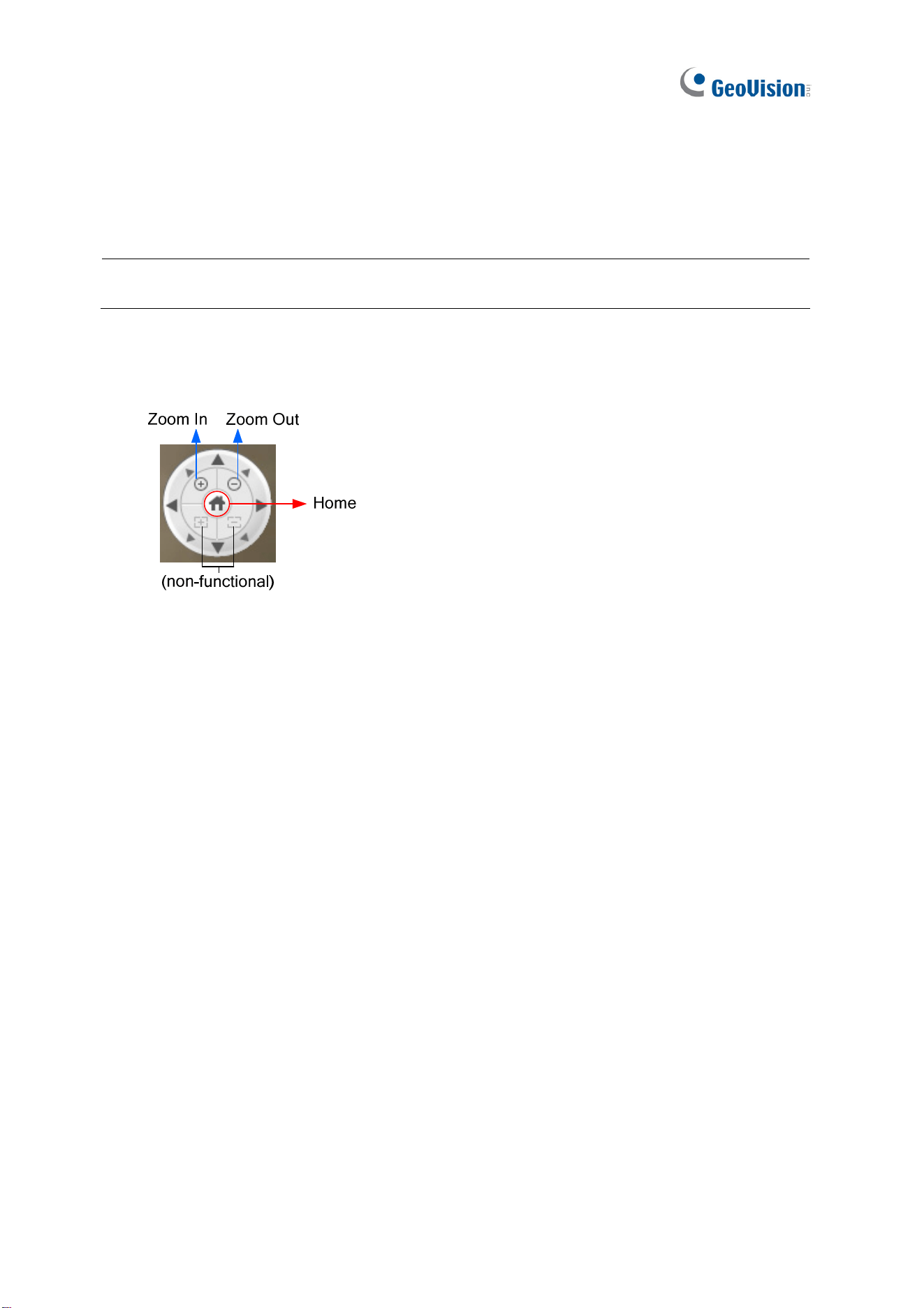
104
5.1.6 Digital PTZ Control
In non-PTZ cameras, the Digital PTZ (DPTZ) function allows you to simulate the PTZ
movement on the screen. This function is also supported in PT / PTZ cameras.
Note: The Digital PTZ function is not supported in the 16-division and 9-division display on
GV-SNVR1600.
1. Right-click the live view of a desired camera and select Digital PTZ. The DPTZ control
panel appears at the lower-right corner of the camera view.
Figure 5-8
2. To zoom in or zoom out, click the corresponding buttons or use the mouse scroll. To
bring the digital PTZ view back to its default image, click Home.
3. To pan and tilt the digital PTZ view, zoom in on the image first, and click and hold one of
the eight directional arrows.
4. To adjust the transparency level of the DPTZ control panel, right click the camera view,
find Digital PTZ and select Transparency. Ten levels range from 10% (fully transparent)
to 100% (fully opaque).
5. To close the DPTZ control panel, right click the camera view and select Exit.
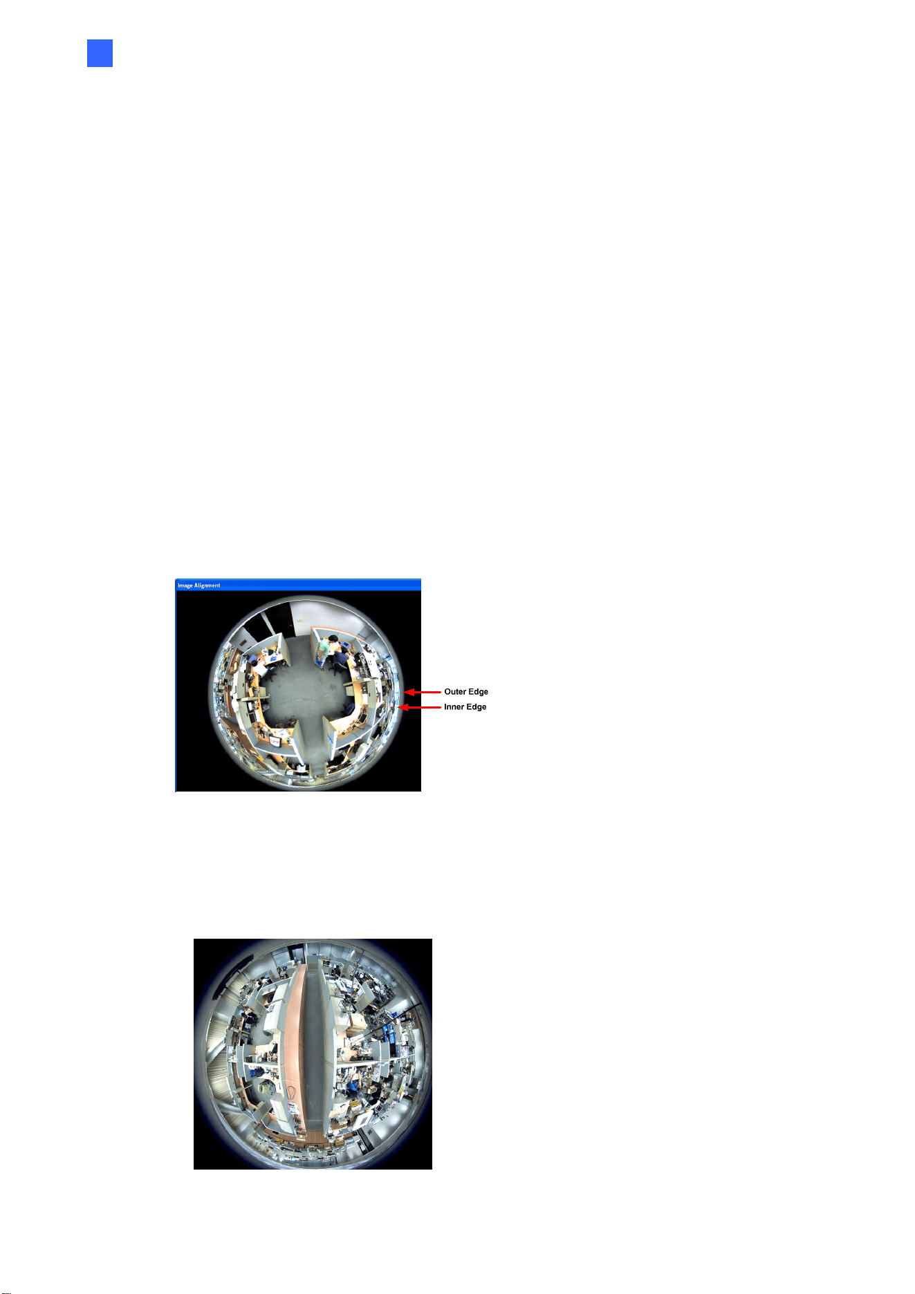
Accessing through Web Browser
105
5
5.1.7 Fisheye View
Only for GV-SNVR0411 / 0412 / 0811 / 0812 / 1611 that connects to GeoVision IP Fisheye
cameras. A fisheye camera allows you to cover all angles of a location with just one camera.
Using different fisheye view modes, the distorted hemispherical image produced by the
fisheye camera can be converted to a conventional rectilinear projection.
To enable fisheye options, right click the live view of a desired fisheye camera and select
Geo Fisheye. Right click the image again and select Fisheye Option to see the following
options.
Image Alignment: By default, the image should be properly aligned already. If not,
follow the steps below to align the image for each model:
GV-EFER3700-W / 3700, GV-FE3402 / 3403 / 5302 / 5303, GV-FER3402 / 3403 /
5302 / 5303 / 5700 / 5701 / 5702 / 12203 / 12700, and GV-QFER12700: Align the
red circle with the outer edge of the camera image, and then align it with the inner
edge of the image frame to achieve optimal results.
Figure 5-9
GV-FE2301 / 4301: Align the red circle with the edge of the camera image. You can
eliminate the darker areas toward the edge of the image by making the red circle
smaller, but the field of view will be slightly reduced.
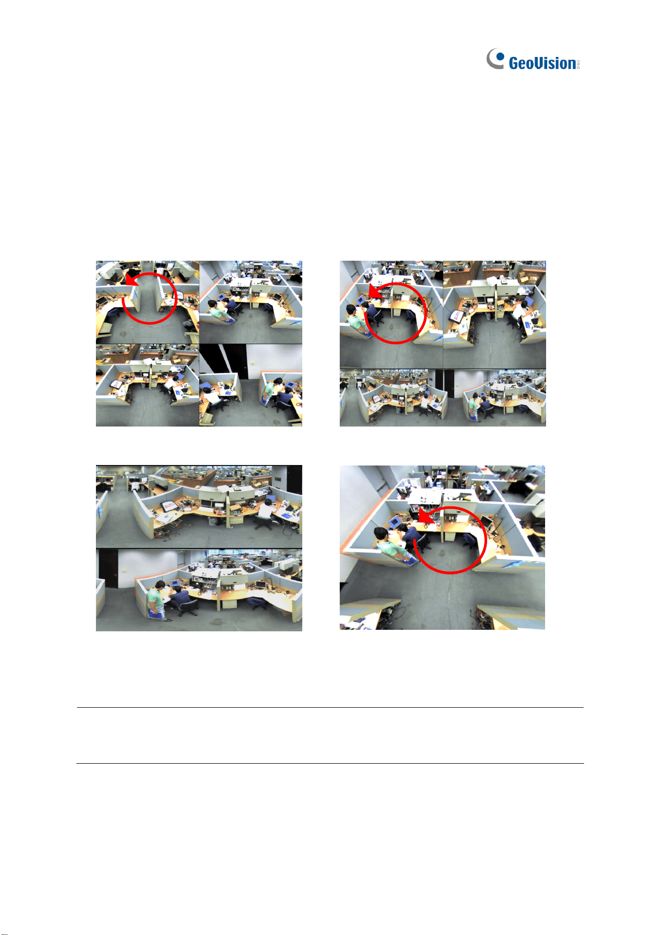
106
Figure 5-10 Once the image of GV-FE2301 / 4301 is aligned, all four edges of the
image will be cropped slightly.
Camera Modes: You can choose among four view modes.
Quad view: Composed of four PTZ views.
360 degree: Composed of two PTZ view and one 360º panoramic view.
Dual 180 degree: Composed of two 180º views.
Single view: Composed of one PTZ view.
Quad view: four PTZ views
360 degree: two PTZ views & one 360º
view
Dual 180 degree: two 180º views Single view: one PTZ view
Figure 5-11
Note:
1. Fisheye Dewarping is not supported when the channel resolution is configured to 4K.
2. Only one fisheye camera can be dewarped by GV-SNVR at a time.

Accessing through Web Browser
107
5
Camera Position: Select Ceiling, Wall or Ground according to where the camera is
mounted.
Adjust AutoPan Speed At Top-Left Channel: Select low, medium, or high speed to
enable Auto Pan for one PTZ view at the rotation speed of your choice. This option
applies to Quad view, 360º degree and Single view.
Zoom: Select Zoom In or Zoom Out and then click on the image.
Show Source Video at Top-Right Channel: Shows the circular source image in the
top-right quadrant when Quad view is selected.
Settings: The following settings are available.
Wide View: Increase the height of the 180 degree view when camera position is set
to wall mount.
Frame Rate Control: You can set the frame rate of the live view image.
Note: When Camera Position is selected as wall mount, only one 180º view will be
displayed.
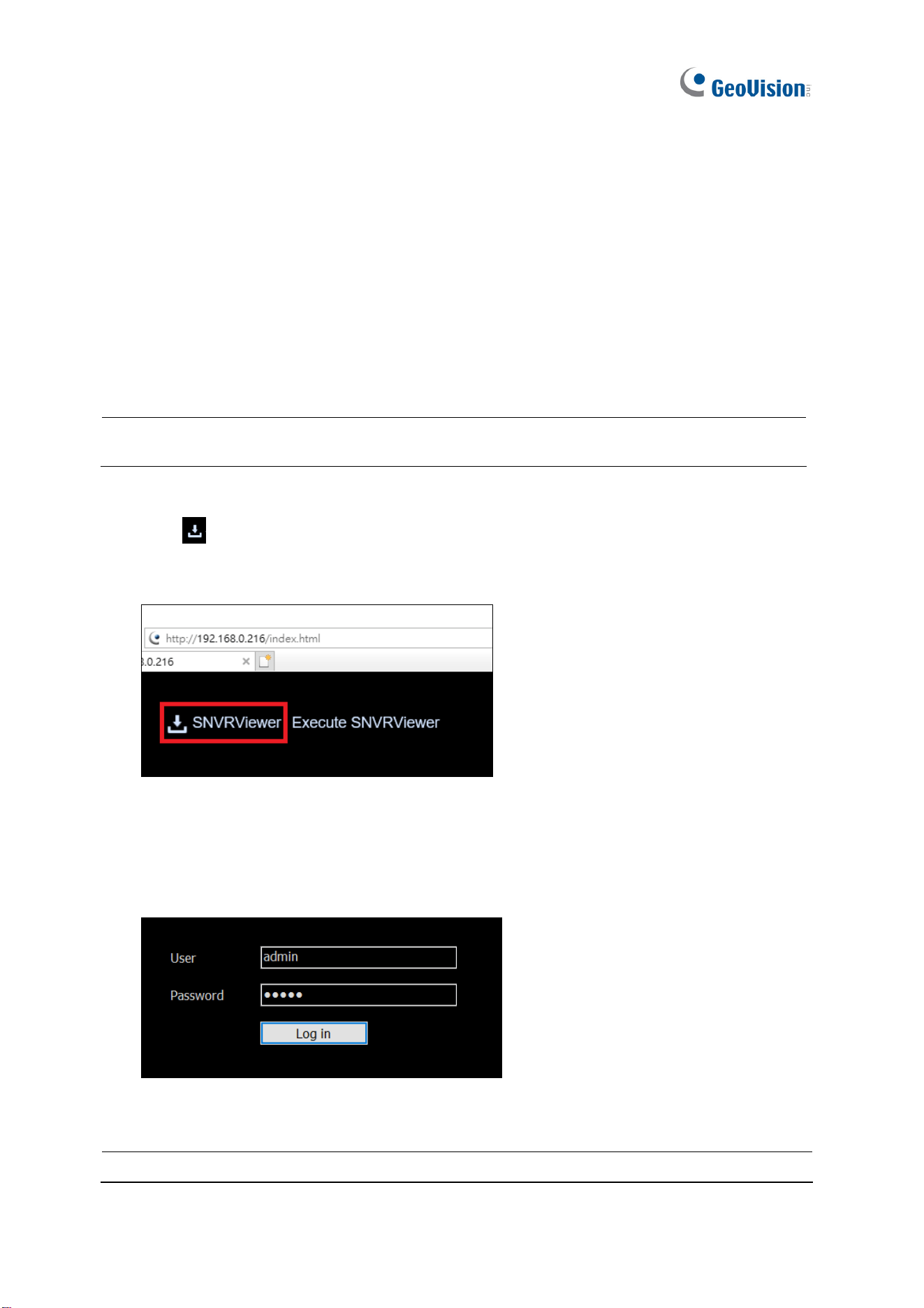
108
5.2 Accessing through SNVR Viewer
Note SNVR Viewer is only supported by GV-SNVR0411 / 0412 / 0811 / 0812 / 1600 / 1611 /
1612.
Through SNVR Viewer, you can remotely connect to GV-SNVR to access live view, play
back recordings, export images and configure the settings of GV-SNVR on any PC.
1. Open your Web browser and type the IP address of GV-SNVR.
Note: To look up the IP address of GV-SNVR, see 3.3 Network. Alternatively, run GV-IP
Device Utility to search for your GV-SNVR. For details, see 6.2 Using GV-IP Device Utility.
2. Click
SNVRViewer at the upper-left corner of the webpage to download and install
SNVR Viewer.
Figure 5-12
3. After the installation is completed, click Execute SNVRViewer at the upper left corner of
the webpage. Type your Username and password and click Log In on the pop-up login
window.
Figure 5-13
Note: Up to two SNVR Viewers can access the same GV-SNVR at a time.
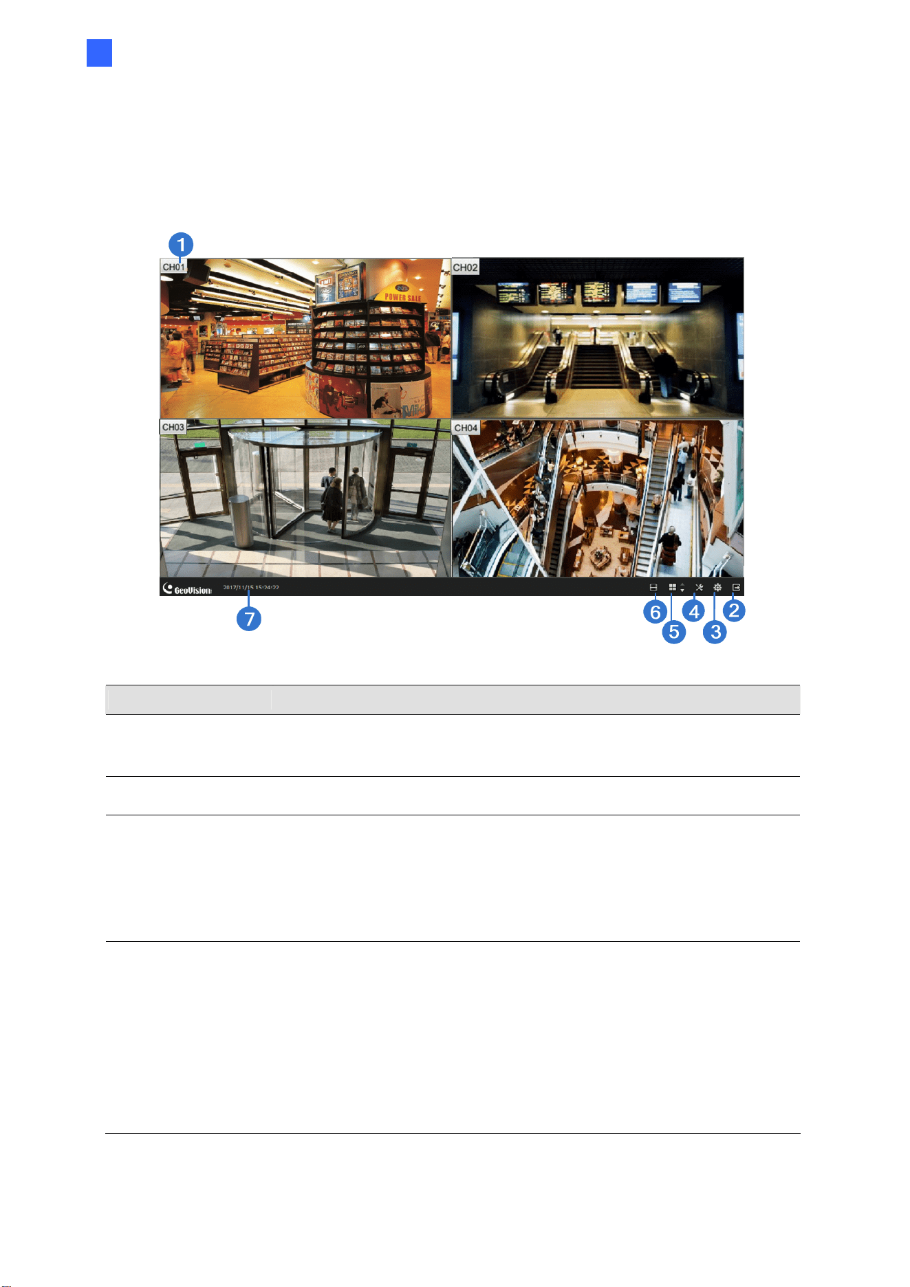
Accessing through Web Browser
109
5
5.2.1 Live View through SNVR Viewer
After successfully logging in SNVR Viewer, you can access the live view of IP cameras
connected to GV-SNVR.
Figure 5-14
No. Name Description
1 Camera Name
Click the camera name to select Mainstream / Sub stream, capture
snapshots, start instant playback, enable speaker, or enable fisheye
dewarping (only applicable to GV-Fisheye cameras).
2 Logout Logs out of GV-SNVR.
3 System
Brings up the following information / options:
˙ The software version of the SNVR Viewer
˙ Display options: Display language and aspect video ratio
preservation
˙ The Snapshot Path in which to save captured snapshots.
˙ The Export Path in which to save exported data.
4 Setting
Accesses the following setting pages:
˙ Camera (see 5.1.2 Camera Settings via Web)
˙ Record (see 3.2 Record)
˙ Network (see 3.3 Network)
˙ Storage (see 2.4 Formatting Hard Drive)
˙ Service (see 3.6 Service)
˙ Event (see 3.7 Event)
˙ System (see 3.8 System)
˙ Account (see 3.9 Account)
110
No. Name Description
5
Division & Page
Up / Down
Selects screen divisions and switch between cameras in single
division.
6 Playback
Displays the playback panel. See 4.1 Timeline Player and 4.2
Recoding Export for details.
7 Date / Time Displays the current date and time.
Note:
1. The SNVR Viewer only connects to the main stream of GV-IP Cameras when using
single division display. For details, see Appendix B Live View Streaming.
2. Configurations of camera settings through GV-SNVR Viewer is only supported by GV-
SNVR0812 V1.05 or later, see 5.1.2 Camera Settings via Web.
3. The Visual Automation function is not supported.

Accessing through Web Browser
111
5
5.3 Accessing through Mobile Devices
To access the live view of GV-SNVR through iOS or Android devices, you must install GV-
Eye app on your mobile device. With GV-Eye, you can watch multiple live views in dual
streams, use Picture in Picture (PIP) function and take snapshots from your mobile device.
For details, see
GV-Eye Installation Guide
.
Note: The Audio function is only supported when IP devices are connected through stream
1.
5.4 Accessing through GV-Edge Recording Manager
You can connect to GV-SNVR from GV-Edge Recording Manager to access live view and
play back recordings. For details, see GV-Edge Recording Manager User’s Manual.
Note:
1. For the versions of GV-Edge Recording Manager compatible with your GV-SNVR, see
1.4.2 Supported GeoVision Applications.
2. The Audio function of live view is only supported in Single Live View Window, and the
IP device must be connected through stream 1.

112
5.5 Accessing through GV-Control Center
You can connect to GV-SNVR from GV-Control Center to access live view and play back
recordings. For details, refer to GV-Control Center User’s Manual.
Note:
1. For the versions of GV-Control Center compatible with your GV-SNVR, see 1.4.2
Supported GeoVision Applications.
2. Audio function of live view is only supported in Single Live View Window and Matrix
View, and the IP device must be connected through stream 1.
5.6 Accessing through RTSP
Note this section is only applicable to SNVR0411 / 0412 / 0811 / 0812 / 1611 / 1612.
You can access the live view of GV-SNVR through RTSP protocol using the following
commands:
˙ rtsp://snvr_<IP of the camera>:554/ch#.sdp
˙ rtsp://<ID>:<Password>@snvr_<IP of the camera>:554/ch#.sdp
Note: Through RTSP, a GV-SNVR0411 / 0811 can be connected by a maximum 20 hosts
at a time, a GV-SNVR0412 / 0812 can be connected by a maximum of 10 hosts at a time,
a GV-SNVR1611 can be connected by a maximum of 50 hosts at a time, and a GV-
SNVR1612 can be connected by a maximum of 16 hosts at a time.
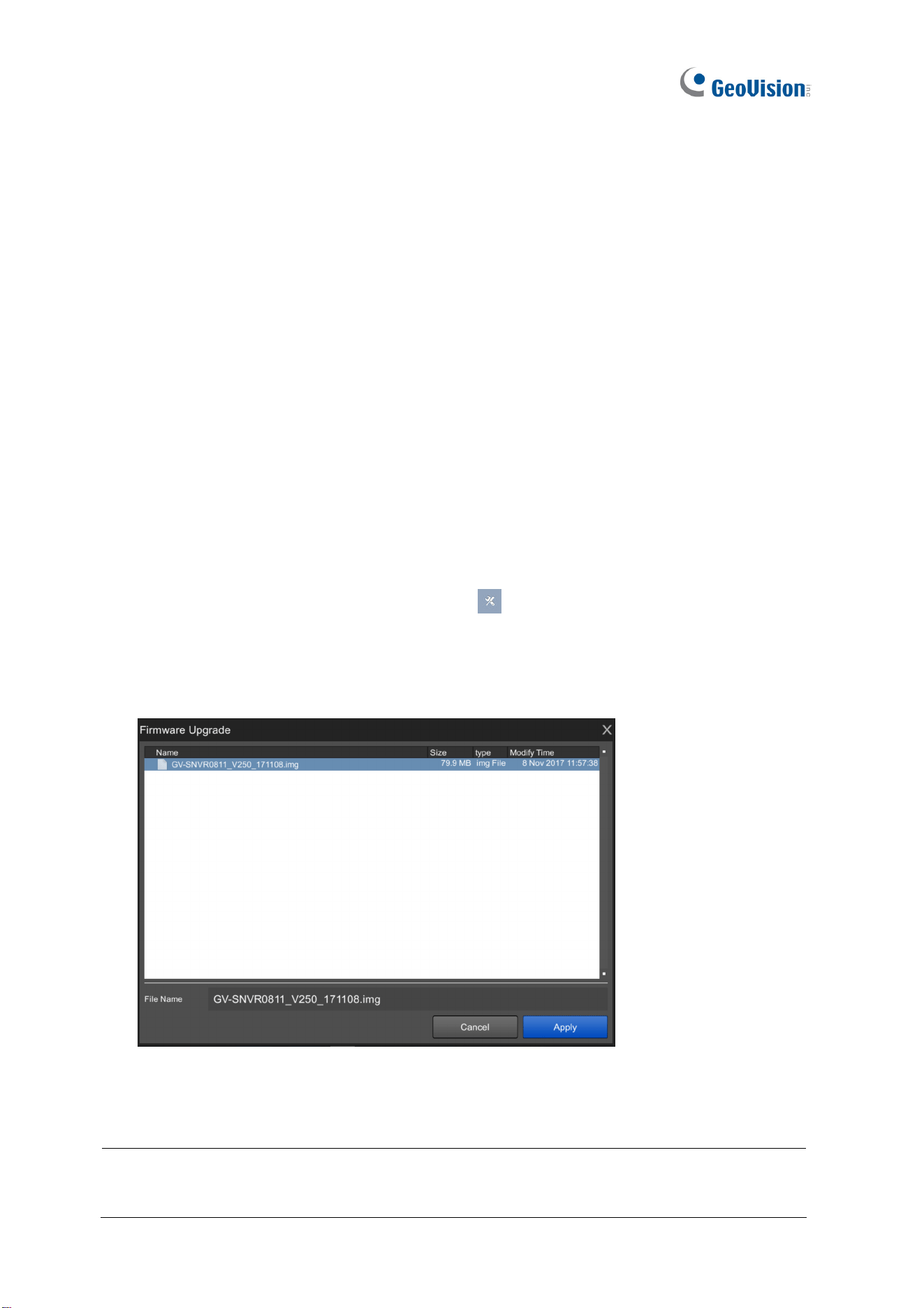
113
Chapter 6 Advanced Applications
6.1 Advanced Options
The Advanced Options function allows you to quickly upgrade firmware and export / import
device settings.
6.1.1 Upgrading System Firmware
GeoVision periodically release the updated firmware on the Website. You can upgrade the
firmware using a USB flash drive of FAT32 format. To upgrade the firmware, follow the steps
below.
1. Download the firmware file to a USB flash drive.
2. Connect the USB drive to GV-SNVR.
3. On the main screen, click the Setting button
and select System.
4. Click the Advanced Option button and select Firmware Upgrade.
5. Find the firmware file and click Apply. The system starts upgrading firmware and
automatically reboots after completing the process.
Figure 6-1
After the system reboots, the main screen will be displayed automatically.
Note: Alternatively, you can use GV-IP Device Utility to upgrade system firmware,
especially for multiple GV-SNVR devices. For details, see Upgrading System Firmware in
6.2 Using GV-IP Device Utility.
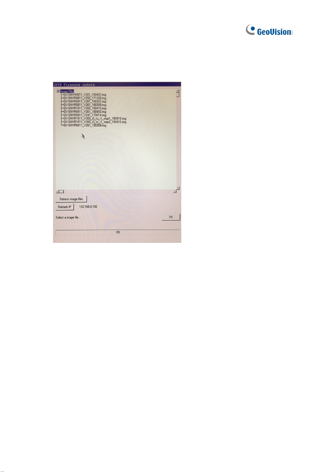
114
6.1.2 Safe Mode of GV-SNVR1611
In the event of a firmware update failure, such as an accidental power outage while updating,
GV-SNVR automatically switches to Safe Mode upon startup.
Figure 6-2
Select the firmware file of GV-SNVR and click OK.

Advanced Applications
115
6
6.1.3 Backing Up and Restoring Settings
You can back up the configurations of GV-SNVR and restore the backup data to the current
GV-SNVR or import it to another one using a USB flash drive.
1. Connect the USB drive to GV-SNVR.
2. On the main screen, click the Setting button
and select System.
To back up the settings:
3. Click the Advanced Option button and select Export Settings.
4. Name the file and select Apply.
5. Select Confirmation. The settings are now successfully saved to your USB flash drive.
To restore the settings:
6. Click the Advanced Option button and select Import Settings.
7. Select the backup file (.dat) and select Apply.
8. Click the Execute button to start restoring. The system will restart after the restoration is
completed.
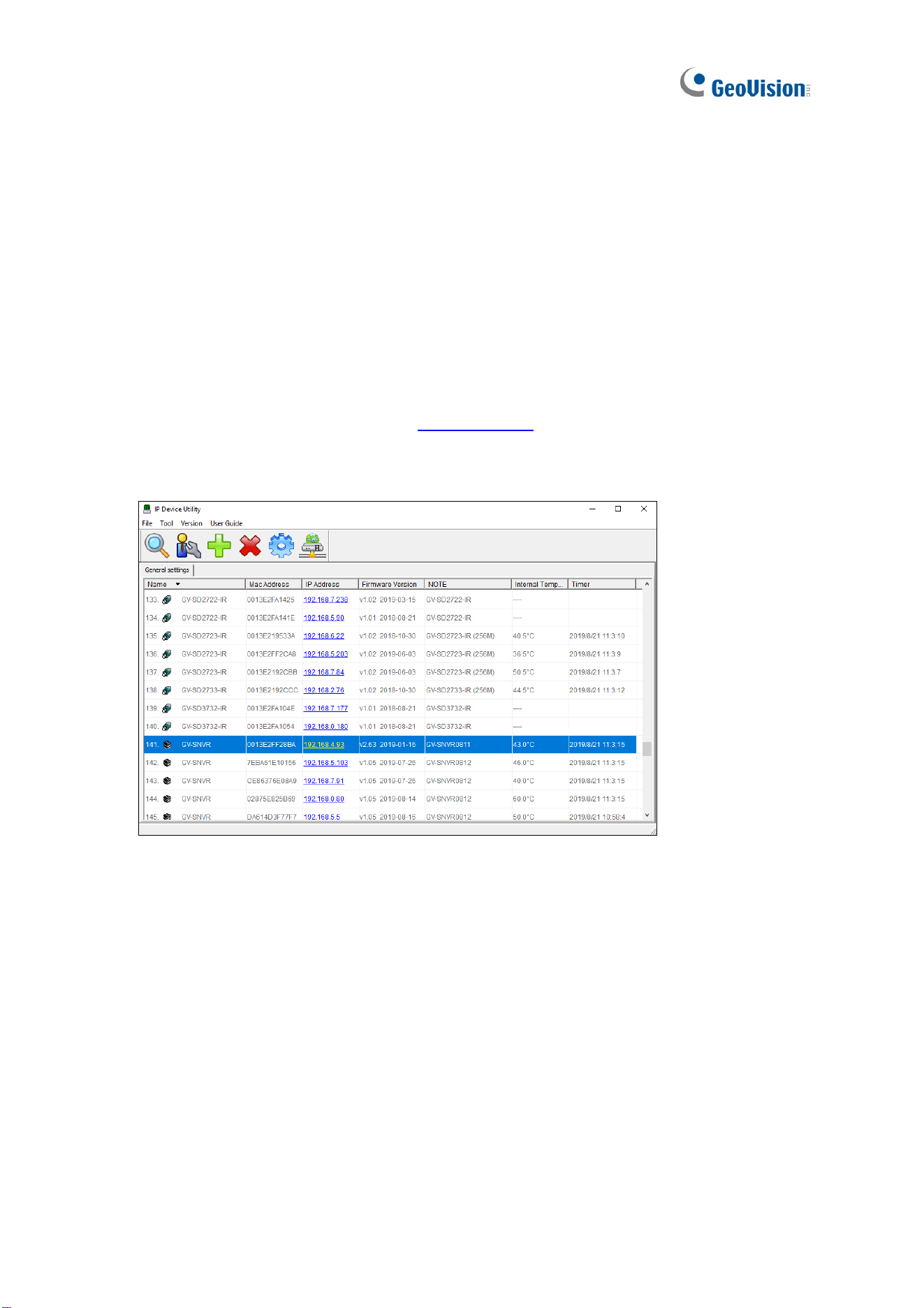
116
6.2 Using GV-IP Device Utility
GV-IP Device Utility detects all the GeoVision IP devices in a LAN and allows you to quickly
set up the IP address of the device, upgrade firmware and export/import device settings.
6.2.1 Looking Up the IP Address
You can use GV-IP Device Utility to look up the IP address of your GV-SNVR and GV-IP
Camera.
1. Install GV-IP Device Utility from the
download page
.
2. Double-click the GV-IP Device Utility icon created on your desktop. This window appears
and IP devices under the same LAN are automatically detected.
Figure 6-3
3. Double-click the IP device and select Web Page to access its Web interface.
6.2.2 Accessing the Live View
You can use GV-IP Device Utility for quick access to the live view of IP cameras connected
with GV-SNVR.
1. Double-click GV-SNVR in the list and select Live View.
2. Select a camera and type the username and password of the camera to access the live
view.
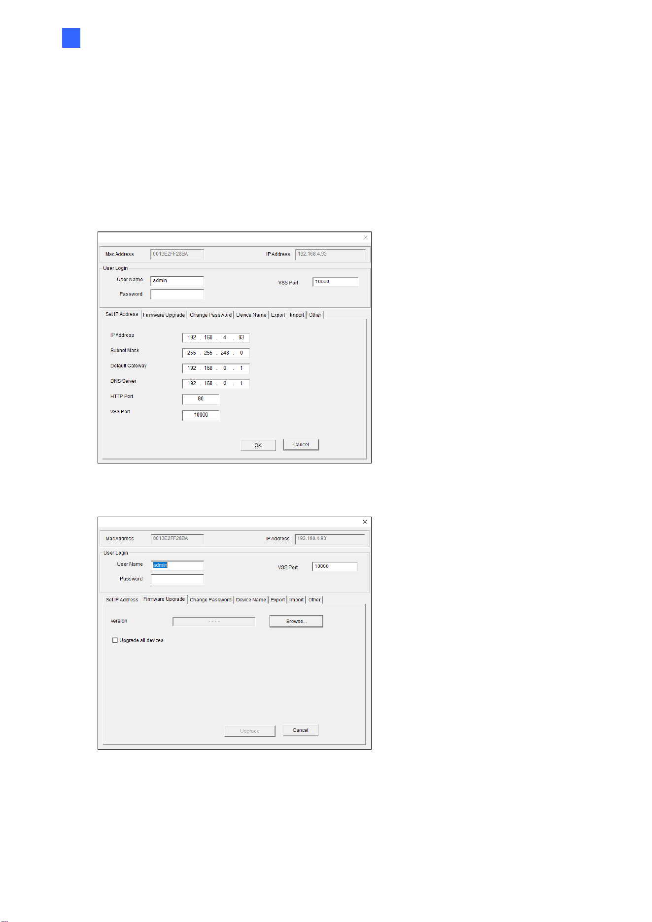
Advanced Applications
117
6
6.2.3 Upgrading System Firmware
You can also use GV-IP Device Utility to upgrade firmware of multiple GV-SNVR devices at
a time. Note the computer used to upgrade firmware must be under the same LAN as GV-
SNVR.
1. Double-click GV-SNVR in the list and select Configure. This dialog box appears.
Figure 6-4
2. Click the Firmware Upgrade tab. This page appears.
Figure 6-5
3. Click the Browse button to locate the firmware file (.img) saved at your local computer.
4. To upgrade all the GV-SNVR devices in the list, select Upgrade all devices.
5. Type Password, and click Upgrade to start the upgrade.
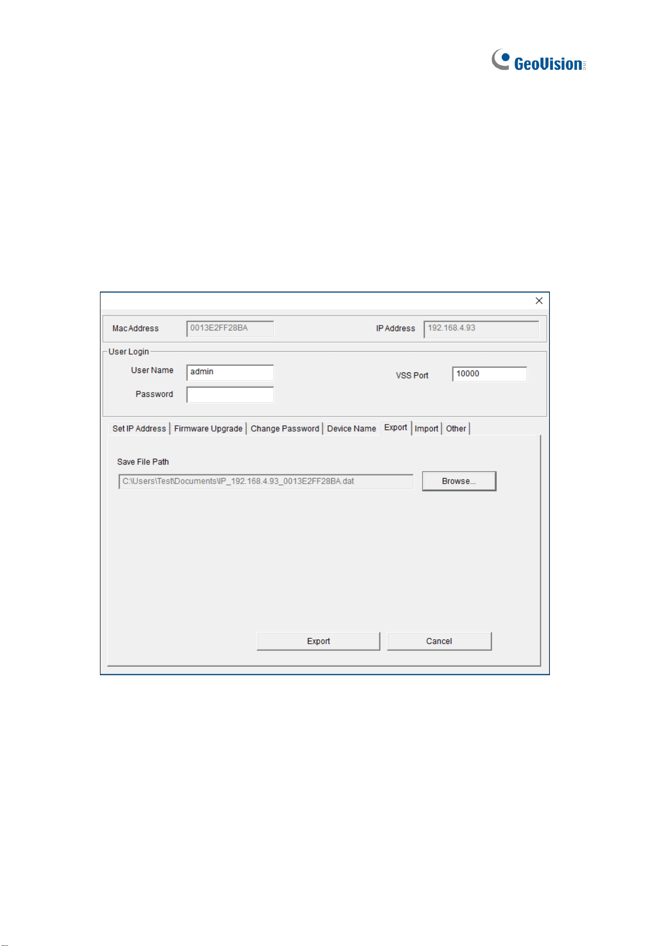
118
6.2.4 Backing Up and Restoring Settings
With GV-IP Device Utility, you can back up the configurations of GV-SNVR and restore the
backup data to the current GV-SNVR or import it to another one.
To back up the settings:
9. Run GV-IP Device Utility and locate the desired GV-SNVR.
10. Double-click GV-SNVR in the list and select Configure.
11. Click the Export tab. This window appears.
Figure 6-6
12. Click the Browse button to assign a file path.
13. Type the Password of GV-SNVR, and click the Export button to save the backup file.
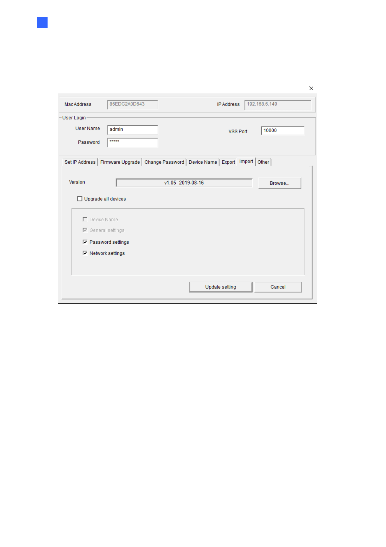
Advanced Applications
119
6
To restore the settings:
14. In Figure 6-5, click the Import tab. This dialog box appears.
Figure 6-7
15. Click the Browse button to locate the backup file (.dat).
16. Select Upgrade all devices to import the settings into all GV-SNVR devices under the
same LAN. To import password settings and/or network settings, select Password
Settings and/or Network settings.
17. Click the Update Settings button to start restoring.
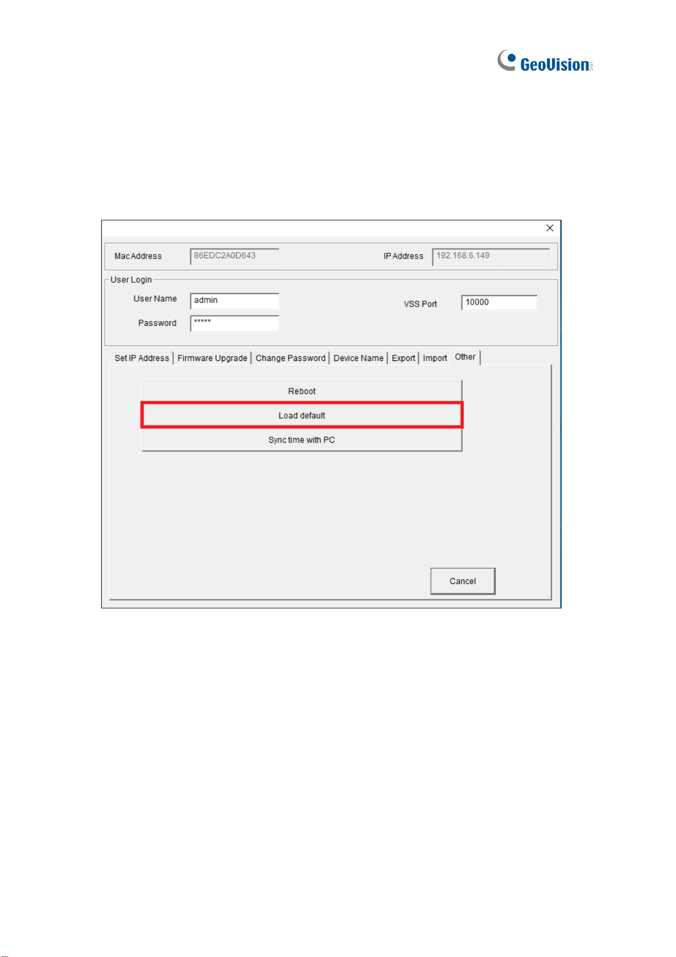
120
6.2.5 Restoring to Factory Default Settings
With GV-IP Device Utility, you can also restore all configurations of your GV-SNVR back to
its default settings.
1. In Figure 6-5, click the Other tab. This dialog box appears.
Figure 6-8
2. Click the Load default button to restore GV-SNVR back to its factory default settings.
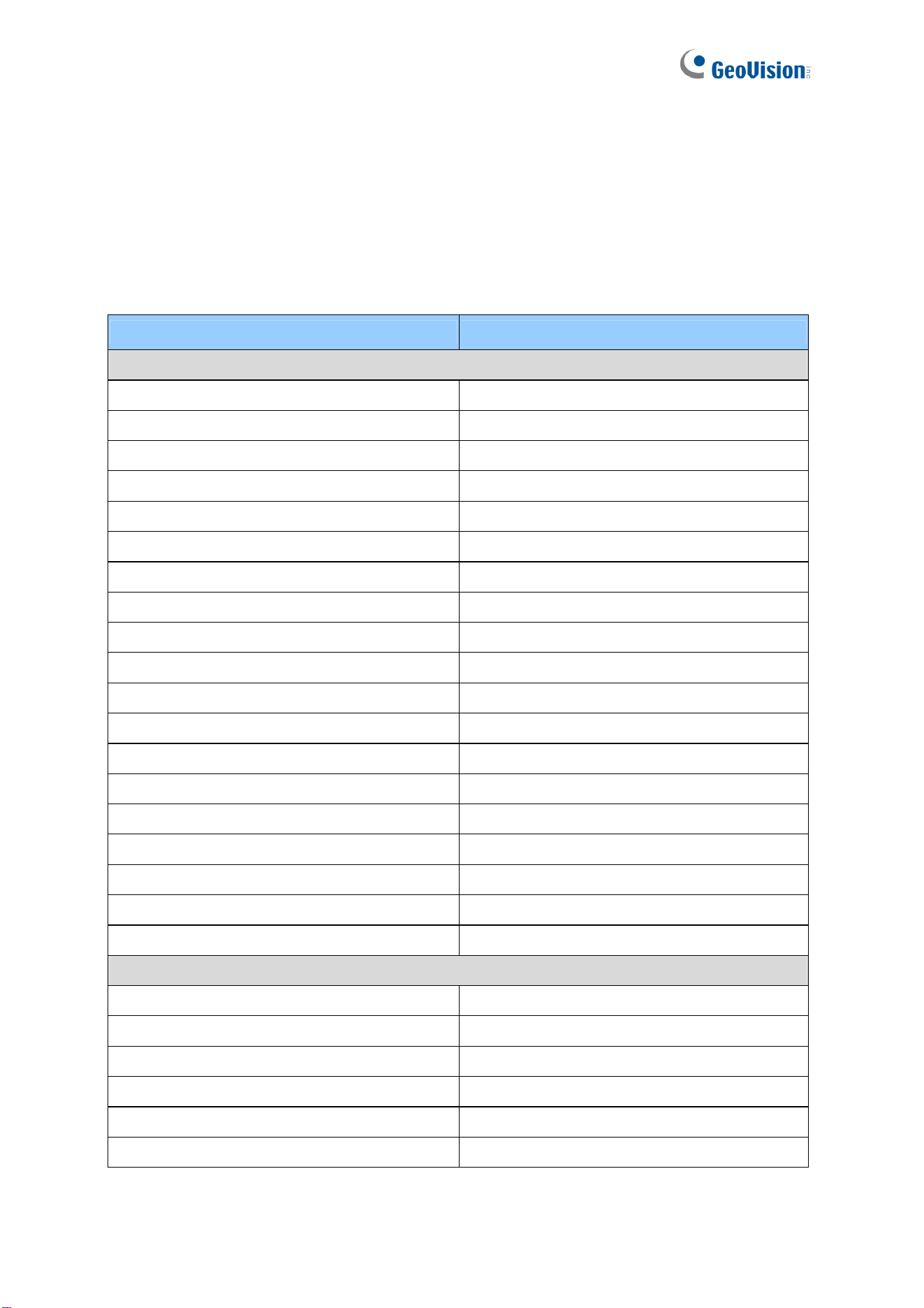
121
Appendix
A. Tested and Supported Hard Disk Drives
For system efficiency, it is recommended to use the enterprise-level hard disk drives instead
of desktop-level or green HDD. The HDD listed below are tested by GeoVision.
Model Capacity
WD
WD101PURZ 10 TB
WD82PURZ 8 TB
WD4000F9YZ 4 TB
WD4000FYYZ 4 TB
WD4001FAEX 4 TB
WD40EFRX 4 TB
WD3000F9YZ 3 TB
WD3000FYYZ 3 TB
WD30EFRX 3 TB
WD30EURS 3 TB
WD30EURX 3 TB
WD2000F9YZ 2 TB
WD2000FYYZ 2 TB
WD20EURS 2 TB
WD20EZRX 2 TB
WD1003FBYZ 1 TB
WD1005FBYZ 1 TB
WD10EURX 1 TB
WD10PURZ 1 TB
WD Ultrastar series
HUH721010ALE604 10 TB
HUS728T8TALE6L4 8 TB
HUS726T6TALE6L4 6 TB
HUS726T4TALE6L4 4 TB
HUS722T2TALA604 2 TB
HUS722T1TALA604 1 TB

Appendix
122
Model Capacity
Seagate
ST8000VE000 8 TB
ST8000VX0002 8 TB
ST8000VX004 8 TB
ST4000NC000 4 TB
ST4000NM0033 4 TB
ST4000VX005 4 TB
ST4000VX013 4 TB
ST3000NM0033 3 TB
ST3000VX000 3 TB
ST2000NC000 2 TB
ST2000VX000 2 TB
ST1000DM003 1 TB
ST1000VX000 1 TB
ST1000VX005 1 TB
Toshiba
MG07ACA10TE 10 TB
MG03ACA400 4 TB
DT01ABA300V 3 TB
MG03ACA300 3 TB
DT01ABA200V 2 TB
DT01ACA200 2 TB
Hitachi
HUA723030ALA640 3 TB
HUS724040ALA640 4 TB
HUS724020ALA640 2 TB
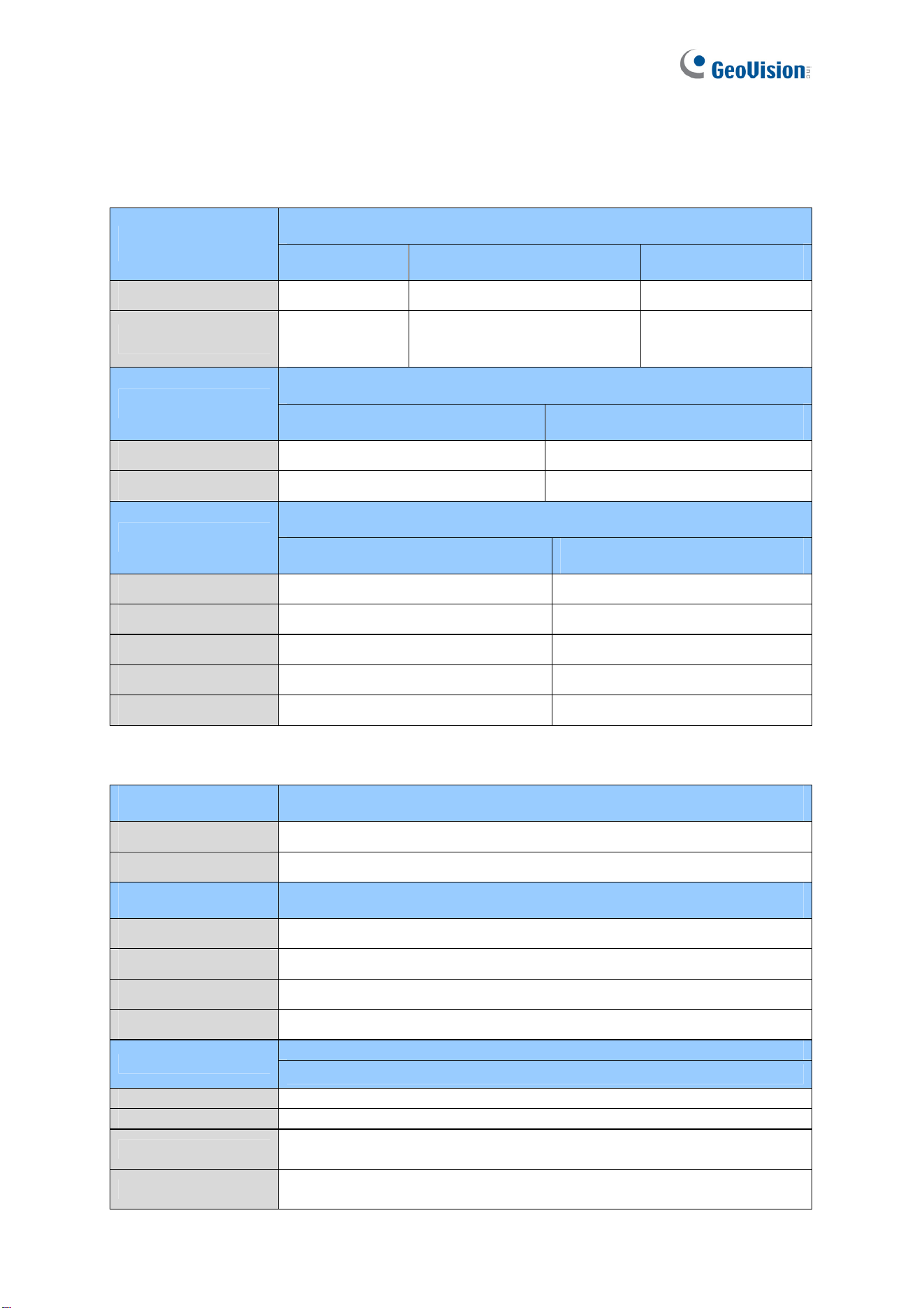
123
B. Live View Streaming
The default streaming for local display and Web browser access are listed below.
GV-SNVR0411
Screen Display
Default One Camera >2M All Camera <=2M
1 Division Stream 1 Stream 1 Stream 1
4 Divisions Stream 2
Channel 1: Stream 2
Other channels: Stream 1
Stream 1
GV-SNVR0412
Screen Display
Default All Camera <= 2M
1 Division Stream 1 Stream 1
4 Divisions Stream 2 Stream 1
GV-SNVR0811 / 0812
Screen Display
Default All Camera <=2M
1 Division Stream 1 Stream 1
4 Divisions Stream 2 Stream 1
6 Divisions Stream 2 Stream 2
8 Divisions Stream 2 Stream 2
9 Divisions Stream 2 Stream 2
Screen Display GV-SNVR0400F
1 Division Stream 1
4 Divisions Stream 1
Screen Display GV-SNVR1600
1 Division Stream 1
4 Divisions Stream 1
9 Divisions Stream 2
16 Divisions Stream 2
GV-SNVR1611
Screen Display
Default
1 Division
Stream 1
4 Divisions
Stream 1
6 Divisions
Channel 1 / 7 / 13: Stream 1
Other channels: Stream 2
8 Divisions
Channel 1 / 9: Stream 1
Other channels: Stream 2
Appendix
124
9 Divisions
Stream 2
16 Divisions
Stream 2
GV-SNVR1612
Screen Display
Default
1 Division
Stream 1
4 Divisions
Stream 1
6 Divisions
Channel 1 / 7 / 13: Stream 1
Other channels: Stream 2
8 Divisions
Channel 1 / 7 / 9: Stream 2
Other channels: Stream 1
9 Divisions
Stream 2
16 Divisions
Stream 2
Note: The resolution of each channel can be adjusted as necessary, with the following
limits:
Up to 16 channels for VGA at 30 fps.
Up to 4 channels for 1080P at 30 fps.
Up to 1 channel for 4K at 30 fps.
125
C. Supported Resolution by GV-SNVR
To see the live view, make sure the resolutions of stream 1 and 2 both meet the
specifications listed below.
Model GV-SNVR0411 / 0412 / 0811 / 0812
Stream Main Stream Sub Stream
2592 x 1944
2560 x 2048
(not available on GV-SNVR0411)
2560 x 1920
2048 x 1536
2048 x 1520
1600 x 1200
1280 x 960
1024 x 768, 960 x 720,
640 x 480, 320 x 240
640 x 480 640 x 480, 320 x 240
4:3
320 x 240 320 x 240
3840 x 2160
2592 x 1520
2560 x 1440
2304 x 1296
1920 x 1080
1280 x 720
1280 x 720, 640 x 360,
448 x 252
640 x 360 640 x 360, 448 x 252
16 : 9 (Default)
448 x 252 448 x 252
1280 x 1024
1280 x 1024, 640 x 512,
320 x 256
640 x 512 640 x 512, 320 x 256
5:4
320 x 256 320 x 256
2176 x 2048
2048 x 1944
1792 x 1696
1440 x 1376
20 : 19
(Fisheye Camera Only)
1280 x 1200
640 x 608
Appendix
126
Model GV-SNVR0400F
Stream Main Stream Sub Stream
1600 x 1200
1280 x 960
640 x 480
CH1
320 x 240
640 x 480, 320 x 240
1600 x 1200
1280 x 960
640 x 480
4:3
CH2 ~ CH4
320 x 240
320 x 240
1920 x 1080
1280 x 720
640 x 360
CH1
448 x 252
640 x 360, 448 x 252
1920 x 1080
1280 x 720
640 x 360
16 : 9 (Default)
CH2 ~ CH4
448 x 252
448 x 252
1280 x 1024
640 x 512
CH1
320 x 256
640 x 512, 320 x 256
1280 x 1024
640 x 512
5:4
CH2 ~ CH4
320 x 256
320 x 256
127
Model GV-SNVR1600
Stream Main Stream Sub Stream
2560 x 1920
2048 x 1536
2048 x 1520
1600 x 1200
1280 x 960
640 x 480
640 x 480, 320 x 240
CH1
320 x 240 320 x 240
1600 x 1200
1280 x 960
640 x 480
640 x 480, 320 x 240
4:3
CH2~CH16
320 x 240 320 x 240
2592 x 1520
2560 x 1440
2304 x 1296
1920 x 1080
1280 x 720
640 x 360
640 x 360, 448 x 252
CH1
448 x 252 448 x 252
1920 x 1080
1280 x 720
640 x 360
640 x 360, 448 x 252
16 : 9 (Default)
CH2~CH16
448 x 252 448 x 252
1280 x 1024
640 x 512
640 x 512, 320 x 256
5:4 CH1~CH16
320 x 256 320 x 256
2048 x 1944
1792 x 1696
1440 x 1376
20 : 19
(Fisheye
Camera Only)
CH1
1280 x 1200
640 x 608
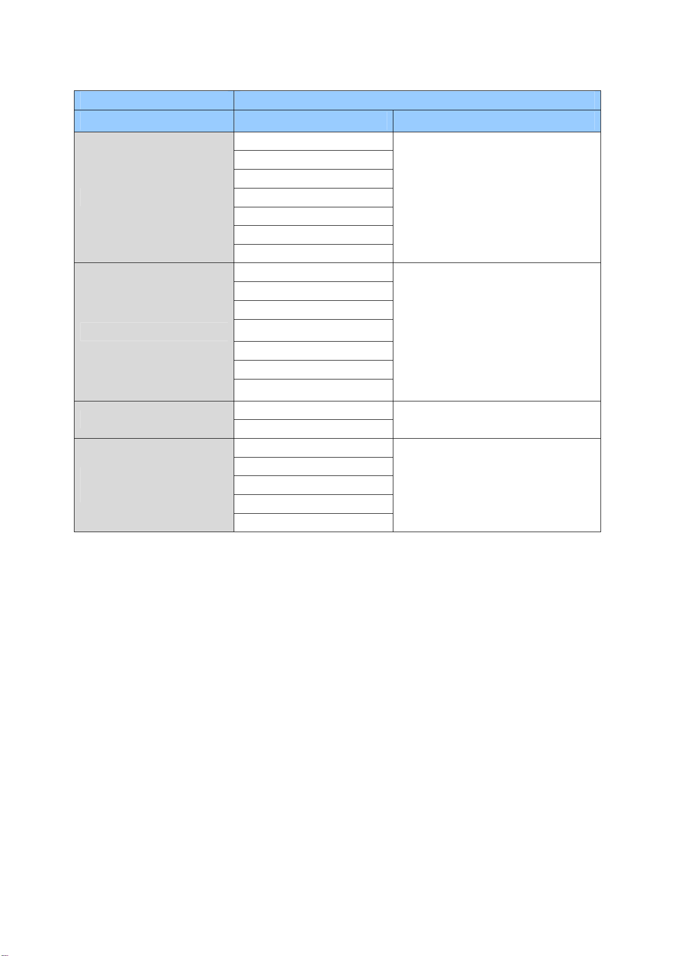
Appendix
128
Model GV-SNVR1611
Stream Main Stream Sub Stream
4000 x 3000
2592 x 1944
2560 x 1920
2048 x 1536
1600 x 1200
1280 x 960
4:3
640 x 480
1280 x 1200,1024 x 768, 960 x
720, 640 x 480, 320 x 240
3840 x 2160
2592 x 1520
2560 x 1440
2304 x 1296
1920 x 1080
1280 x 720
16 : 9 (Default)
640 x 360
1280 x 720, 640 x 360, 448 x 256
1280 x 1024
5:4
640 x 512
1280 x 1024, 640 x 512, 320 x 256
2896 x 2768
2176 x 2048
2048 x 1944
1792 x 1696
20 : 19
(Fisheye Camera Only)
1440 x 1376
960 x 912, 640 x 608
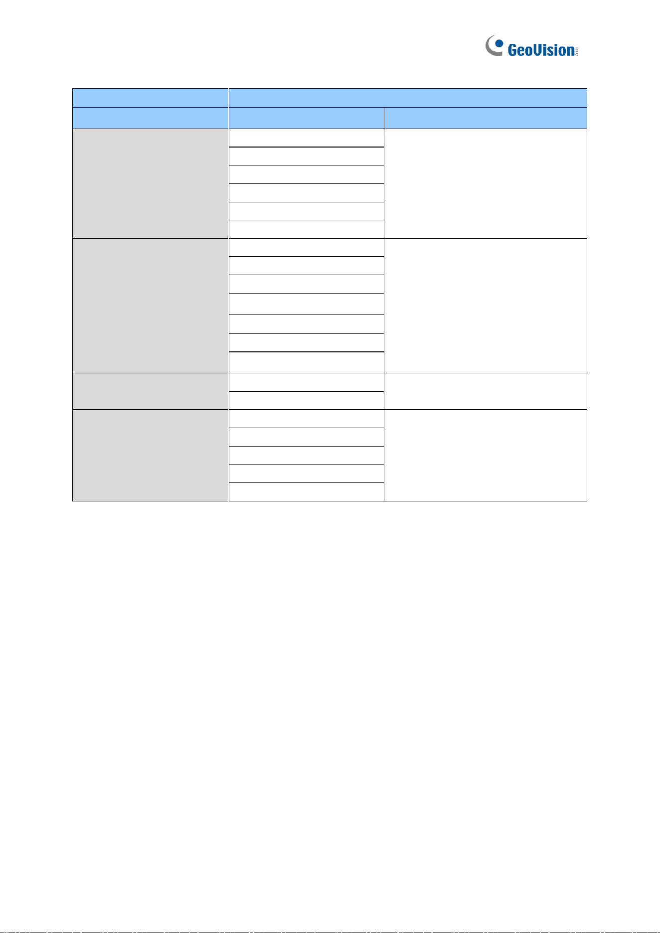
129
Model
GV-SNVR1612
Stream
Main Stream
Sub Stream
4:3
2592 x 1944
1280 x 1200, 1024 x 768,
960 x 720, 640 x 480, 320 x 240
2560 x 1920
2048 x 1536
1600 x 1200
1280 x 960
640 x 480
16 : 9 (Default)
3840 x 2160
1280 x 720, 640 x 360, 448 x 256
2592 x 1520
2560 x 1440
2304 x 1296
1920 x 1080
1280 x 720
640 x 360
5:4
1280 x 1024
1280 x 1024, 640 x 512, 320 x 256
640 x 512
20 : 19
(Fisheye Camera Only)
2896 x 2768
960 x 912, 640 x 608
2176 x 2048
2048 x 1944
1792 x 1696
1440 x 1376