
© 2024 GeoVision, Inc. All rights reserved.
Under the copyright laws, this manual may not be copied, in whole or in part,
without the written consent of GeoVision.
Every effort has been made to ensure that the information in this manual is
accurate. GeoVision, Inc. makes no expressed or implied warranty of any kind
and assumes no responsibility for errors or omissions. No liability is assumed
for incidental or consequential damages arising from the use of the information
or products contained herein. Features and specifications are subject to
change without notice.
GeoVision, Inc.
9F, No. 246, Sec. 1, Neihu Rd.,
Neihu District, Taipei, Taiwan
Tel: +886-2-8797-8377
Fax: +886-2-8797-8335
http://www.geovision.com.tw
Trademarks used in this manual: GeoVision, the GeoVision logo and GV
series products are trademarks of GeoVision, Inc. Windows is the registered
trademark of Microsoft Corporation.
September 2024
Scan the following QR codes for product warranty and technical support
policy:
[Warranty] [Technical Support Policy]
Preface
Welcome to the GV-R Series SNVR User’s Manual.
IMPORTANT: The features described in the manual vary among SNVR models and firmware
versions. Some features may not be available in your SNVR.
This Manual is designed for the following models:
Model
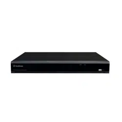
GV-RNVR256G0-N
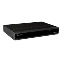
GV-RNVR3240-N
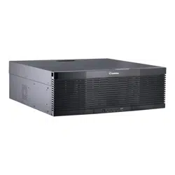
GV-RNVRL810-P

Contents
Preface ........................................................................................................................................................... 1
Contents ........................................................................................................................................................ 1
SAFETY INSTRUCTION ............................................................................................................................... 4
Chapter 1 Product Overview ................................................................................................................... 1
1.1 GV-RNVR256G0-N Front View .................................................................................................................. 1
1.2 GV-RNVR256G0-N Rear View ................................................................................................................... 2
1.3 GV-RNVR3240-N Front View .................................................................................................................... 3
1.4 GV-RNVR3240-N Rear View ...................................................................................................................... 4
1.5 GV-RNVRL810-P Front View..................................................................................................................... 5
1.6 GV-RNVRL810-P Rear View ...................................................................................................................... 6
Chapter 2 NVR Installation & Connection ............................................................................................. 7
2.1 HDD Installation ........................................................................................................................................ 7
2.1.1 GV-RNVR256G0-N ........................................................................................................................................... 7
2.1.2 GV-RNVR3240-N............................................................................................................................................... 9
2.1.3 GV-RNVRL810-P ............................................................................................................................................. 10
2.2 Connection Diagram ................................................................................................................................ 11
2.3 Power Supply Connection ..................................................................................................................... 12
Chapter 3 NVR Common Operations ................................................................................................... 13
3.1 Using the Supplied Mouse ..................................................................................................................... 13
3.2 Using the Virtual Keyboard .................................................................................................................... 13
3.3 Password ................................................................................................................................................. 14
3.3.1 Password Generation...................................................................................................................................... 14
3.3.2 Reset Password ............................................................................................................................................... 16
Chapter 4 NVR Starting up..................................................................................................................... 20
4.1 Start Wizard ............................................................................................................................................. 20
4.1.1 Start Wizard ...................................................................................................................................................... 21
4.1.2 Network Configuration .................................................................................................................................... 22
4.1.3 Date/Time ......................................................................................................................................................... 25
4.1.4 IP Camera ......................................................................................................................................................... 27
4.1.5 Disk .................................................................................................................................................................... 29
4.1.6 Resolution ......................................................................................................................................................... 30
4.1.7 Mobile ................................................................................................................................................................ 30
4.1.8 Summary ........................................................................................................................................................... 31
4.2 Live View Screen Overview .................................................................................................................... 32
4.2.1 Camera Quick Toolbar .................................................................................................................................... 33
4.2.2 Taskbar .............................................................................................................................................................. 34
4.2.3 Status Bar ......................................................................................................................................................... 35
4.2.4 Start Menu ........................................................................................................................................................ 36

4.2.5 Fisheye Camera............................................................................................................................................... 39
4.2.6 Alarm Notification Panel ................................................................................................................................. 41
Chapter 5 NVR System Setup ............................................................................................................... 42
5.1 Channel .................................................................................................................................................... 42
5.1.1 IP Channels ......................................................................................................................................................... 42
5.1.2 Live .................................................................................................................................................................... 51
5.1.3 Image Control ................................................................................................................................................... 53
5.1.4 PTZ .................................................................................................................................................................... 56
5.1.5 Motion ................................................................................................................................................................ 66
5.1.6 ROI .................................................................................................................................................................... 68
5.1.7 Video Cover / Privacy Zone............................................................................................................................ 69
5.2 Record ..................................................................................................................................................... 70
5.2.1 Video Encoding ................................................................................................................................................ 70
5.2.2 Audio Encoding ................................................................................................................................................ 72
5.2.3 Record ............................................................................................................................................................... 73
5.2.4 Image Capture ................................................................................................................................................. 75
5.3 Alarm........................................................................................................................................................ 77
5.3.1 Motion ................................................................................................................................................................ 77
5.3.2 I/O Alarm ........................................................................................................................................................... 79
5.3.3 Intelligent Alarm ............................................................................................................................................... 80
5.3.4 Combination Alarm .......................................................................................................................................... 81
5.3.5 PTZ Linkage ..................................................................................................................................................... 83
5.3.6 Exception .......................................................................................................................................................... 84
5.3.7 Voice Prompts .................................................................................................................................................. 85
5.3.8 Siren .................................................................................................................................................................. 89
5.3.9 Disarming .......................................................................................................................................................... 90
5.3.10 Alarm Schedule ............................................................................................................................................. 92
5.4 AI .............................................................................................................................................................. 93
5.4.1 Setup ................................................................................................................................................................. 94
5.4.2 Face Recognition ........................................................................................................................................... 118
5.4.3 Alarm ............................................................................................................................................................... 130
5.4.4 Statistics .......................................................................................................................................................... 138
5.5 Network .................................................................................................................................................. 142
5.5.1 General ........................................................................................................................................................... 142
5.5.2 DDNS .............................................................................................................................................................. 149
5.5.3 Email ................................................................................................................................................................ 150
5.5.4 HTTPS............................................................................................................................................................. 153
5.5.5 IP Filter ............................................................................................................................................................ 154
5.5.6 Voice Assistant ............................................................................................................................................... 156
5.5.7 Platform Access ............................................................................................................................................. 168
5.5.8 GV-VPN ........................................................................................................................................................... 172
5.6 Storage .................................................................................................................................................. 173
5.6.1 Disk .................................................................................................................................................................. 173
5.6.2 Cloud ............................................................................................................................................................... 183

5.6.3 FTP .................................................................................................................................................................. 187
5.7 System ................................................................................................................................................... 189
5.7.1 General ........................................................................................................................................................... 189
5.7.2 Multi-user ........................................................................................................................................................ 195
5.7.3 Maintenance ................................................................................................................................................... 199
5.7.4 IP Camera Maintain ....................................................................................................................................... 205
5.7.5 System Information ....................................................................................................................................... 209
Chapter 6 AI Scenario ........................................................................................................................... 212
6.1 Cross Counting ..................................................................................................................................... 212
6.1.1 Channel View Setup ......................................................................................................................................... 215
6.1.2 Group View Setup ............................................................................................................................................ 218
6.1.3 Advertise Mode ................................................................................................................................................. 220
6.1.4 Search Counting Data ..................................................................................................................................... 222
6.2 Face Attendance ................................................................................................................................... 223
6.3. Object Classification .............................................................................................................................. 225
Chapter 7 Search, Playback & Backup .............................................................................................. 227
7.1 Using Search Function ......................................................................................................................... 227
7.1.1 Search & Play Video in General .................................................................................................................. 229
7.1.2 Event Search, Playback & Backup .............................................................................................................. 231
7.1.3 Sub-periods Playback ................................................................................................................................... 234
7.1.4 Smart Search ................................................................................................................................................. 235
7.1.5 Tag Search...................................................................................................................................................... 237
7.1.6 Play External File ........................................................................................................................................... 238
7.1.7 Picture Search & View .................................................................................................................................. 239
7.1.8 Slice Search ................................................................................................................................................... 241
7.1.9 AI Search ........................................................................................................................................................ 242
Chapter 8 Remote Access via Web Client ......................................................................................... 259
8.1 Basic System Environment Requirements ......................................................................................... 259
8.2 Web Plugin Download and Installation ............................................................................................... 259
8.3 Web Client Manager .............................................................................................................................. 262
8.3.1 Live Interface .................................................................................................................................................. 262
8.3.2 Playback ......................................................................................................................................................... 265
8.3.3 Remote Setting .............................................................................................................................................. 271
8.3.4 Local Setting ................................................................................................................................................... 271
Appendix ................................................................................................................................................... 272
A. Supported Hard Disk Drives ............................................................................................................ 272
B. Troubleshooting ................................................................................................................................ 273
C. Usage Maintenance .......................................................................................................................... 275

SAFETY INSTRUCTION
Carefully read the following safety instruction so as to avoid personal injuries and prevent the
equipment and other connection devices from being damaged.
1. Power sources
Never operate the equipment by using unspecified power supply.
2. Never push objects of any kind through openings of NVR
Never push objects of any kind through openings of NVR so as to avoid electric shock or other
accidents.
3. Do not put the equipment in the dusty field
Do not put the equipment in the dusty field.
4. Do not place the equipment under rain or humid environment
Do not place the equipment under humid environment like basement. If the equipment is
accidentally in contact with water, unplug the power cable and immediately contact your local
dealer.
5. Keep the surface of the equipment clean and dry
Use soft damp cloth to clean the outer case of NVR (do not use liquid aerosol cleaners)
6. Do not operate if any problems are found
If there are any strange smell or sound from NVR, unplug the power cable and contact the
authorized dealer or service center.
7. Do not try to remove the upper cover
Warning
: Do not remove the cap of NVR so as to avoid electric shock.
8. Handle with care
If NVR does not work normally because of hitting on the hard object, contact the authorized
dealer for repair or replacement.
9. Use standard lithium battery (Use the batteries attached or specified by the
manufacturer)
After cutting off the power supply, if the system clock cannot continue to work, replace the
standard 3V lithium battery on the main board.

Warning:
Turn off NVR before replacing the batteries, or you may be suffered from serious
electric shock. Properly dispose of the used batteries.
10. Put the equipment in a place with good ventilation
The NVR system includes HDD, which produces large amount of heat during operation. As a
result, do not block the ventilation openings (on the top, bottom, both sides and the reverse side)
for cooling the system during operation. Install or put the equipment in the place with good
ventilation.
11. The attached power adapter can only be used for 1 set of NVR. Do not connect more
equipment, or NVR may be restarted repeatedly because of insufficient power.
12. Prevent the equipment from water dropping or splashing. Do not place objects
containing water, such as flower vase, on the equipment.
13. Do not ingest battery, Chemical Burn Hazard,
This product contains a coin / button cell battery.
If the coin / button cell battery is swallowed, it can cause severe internal burns in just 2
hours and can lead to death.
Keep new and used batteries away from children.
If the battery compartment does not close securely, stop using the product and keep it
away from children.
If you think batteries might have been swallowed or placed inside any part of the body,
seek immediate medical attention.
1
Chapter 1 Product Overview
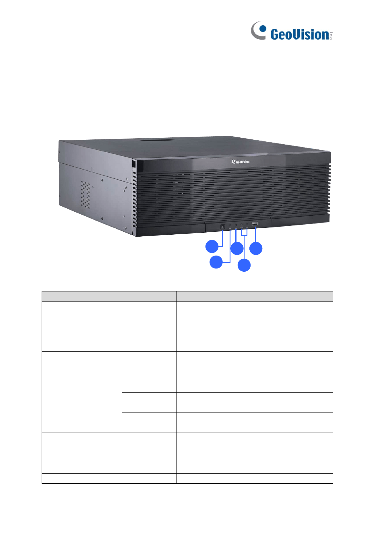
1.1 GV-RNVR256G0-N Front View
1
2
3
4
5
No.
Item
Status
Description
1.
Standby button
It is used to power on/off the system when the
device has a constant power supply. You can
press and hold the button for three seconds to shut
down the device, and you can press and hold the
key for 10 seconds to forcedly restart the device.
2.
Power LED
Solid on
The device is operating properly.
Not lit
The device is shut down or not powered on.
3.
HDD LED
Lit green
The hard disk is operating properly and no data is
read or written.
Flash green
The hard disk is operating properly and there is
data read or written.
Not lit
The hard disk cannot be detected or the hard disk
is faulty.
4.
LAN1 /2 LED
Solid on
The hard disk is operating properly and no data is
read or written.
Not lit
The hard disk is operating properly and there is
data read or written.
5.
USB Port
Connected to a mobile USB device or a mouse.
2
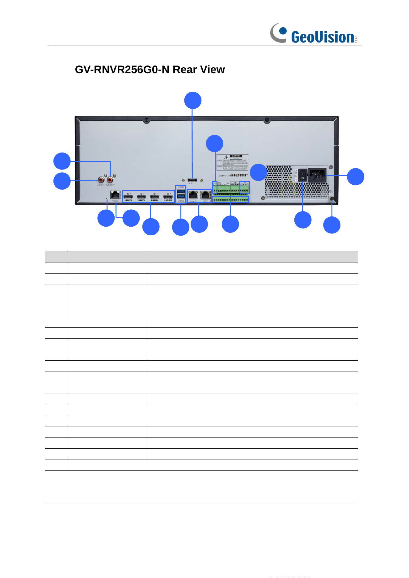
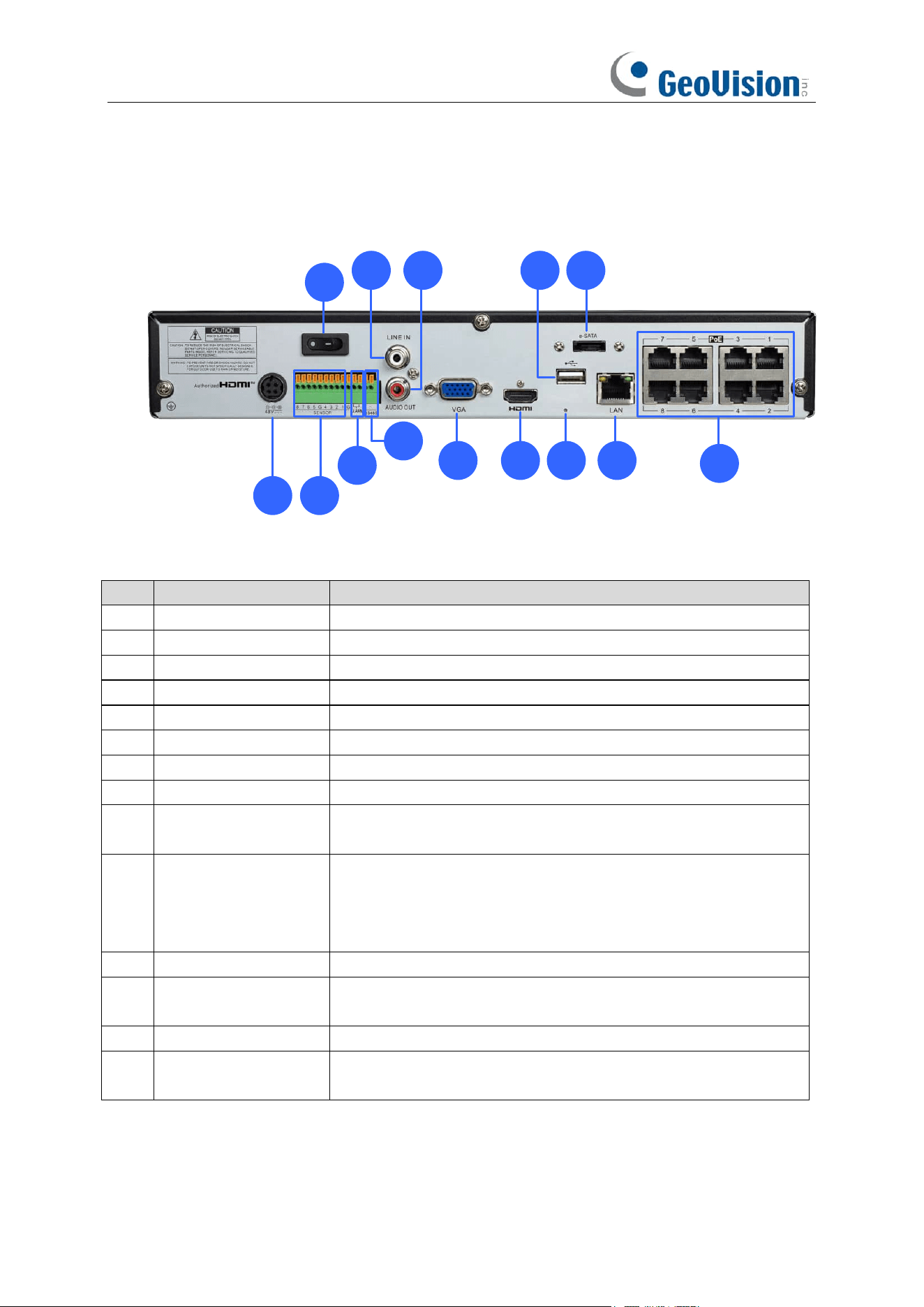
1.2 GV-RNVR256G0-N Rear View
1
2
3 4
5
7
6
8
9
10
12
13
11
14
No.
Item
Description
1.
Audio input
Connected to an analog audio input device.
2.
Audio output
Connected to an analog audio output device.
3.
Reset button
Used to restore the factory settings. You can press and hold the
button for 10 seconds to make the system automatically restore
the factory settings, and the buzzer rings four times at the same
time.
4.
RS232 interface
It is currently not functional.
5.
HDMI 1/2/3/4
Output interface of the device, supporting output with
8K/4K/1080p resolution.
6.
USB Port
Connect a USB device, such as USB mouse and USB flash disk.
7.
e-SATA
Connected to an external storage device. A maximum of one
hard disk is supported.
8.
LAN1/2
Gigabit network interface for connecting network cables.
9.
RS-485 interface
Connected to a speed dome camera.
10.
Alarm output interface
Connected to alarm output devices.
11.
Alarm input interface
Connected to alarm input devices.
12.
Power switch
Used to power on/off the device.
13.
Power Port
Connect the attached power supply.
14.
Grounding Terminal
Connect to the grounding cable.
Note: The device only supports HDMI #1 output at 8K. If the output resolution of HDMI #1 is set
to 8K, the maximum output resolution of HDMI #3 and #4 will be limited to 1080P, and HDMI #2
will be disabled.
3
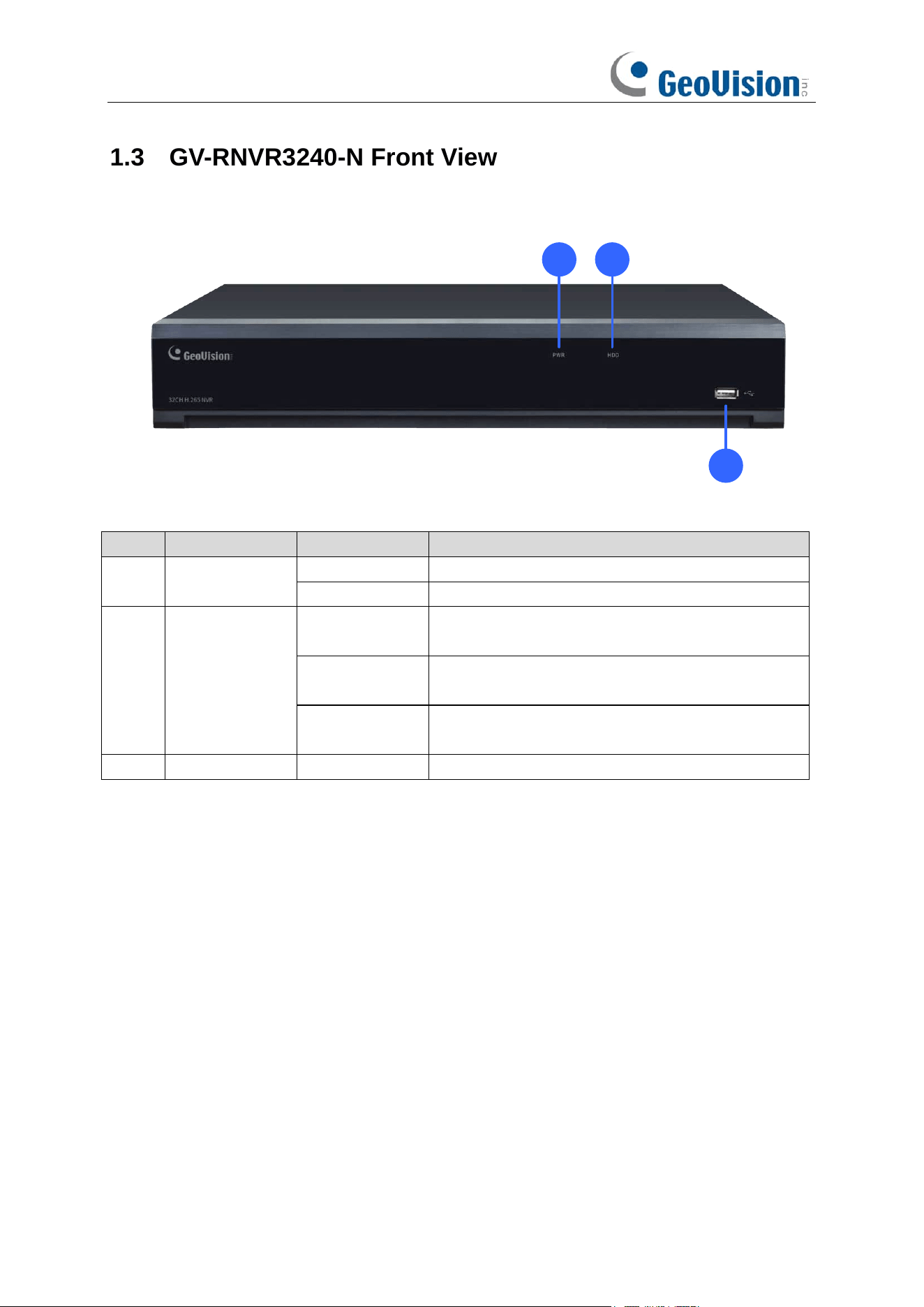
1.3 GV-RNVR3240-N Front View
1 2
3
No.
Item
Status
Description
1.
Power LED
Solid on
The device is operating properly.
Not lit
The device is shut down or not powered on.
2.
HDD LED
Lit red
The hard disk is operating properly and no data is
read or written.
Flash red
The hard disk is operating properly and there is
data read or written.
Not lit
The hard disk cannot be detected or the hard disk
is faulty.
3.
USB Port
Connected to a mobile USB device or a mouse.
4
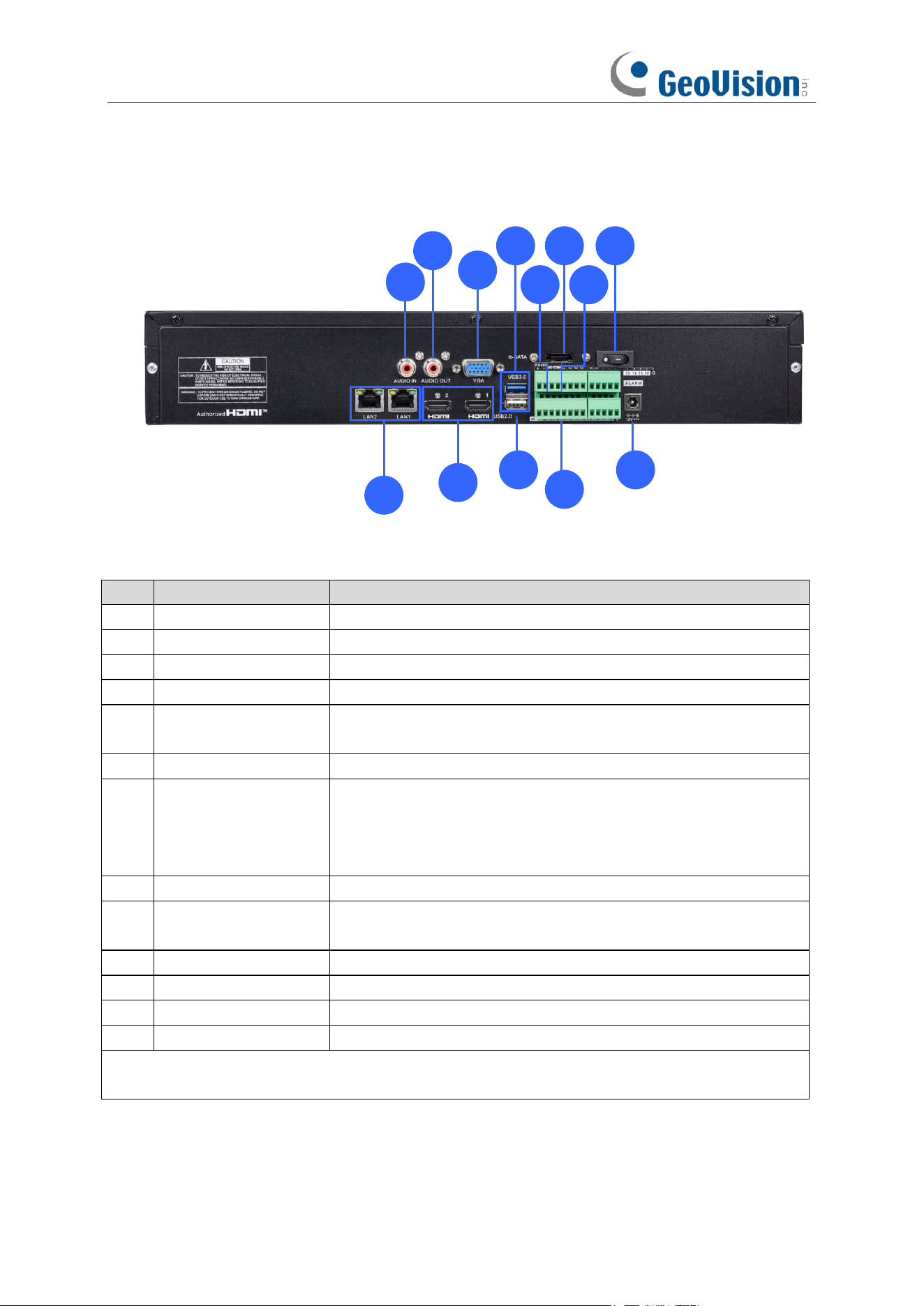
1.4 GV-RNVR3240-N Rear View
1
2
3
4
5
6
8
7
10
12
119
13
No.
Item
Description
1.
LAN1/2
Gigabit network interface for connecting network cables.
2.
Audio input
Connected to an analog audio input device.
3.
Audio output
Connected to an analog audio output device.
4.
VGA
Connected to a VGA monitor.
5.
HDMI 1/2
Output interface of the device, supporting output with up to 4K
resolution.
6.
USB Port
Connect a USB device, such as USB mouse and USB flash disk.
7.
Reset button
Used to restore the factory settings. You can press and hold the
button for 10 seconds to make the system automatically restore
the factory settings, and the buzzer rings four times at the same
time.
8.
RS-485 interface
Connected to a speed dome camera.
9.
e-SATA
Connected to an external storage device. A maximum of one
hard disk is supported.
10.
Alarm output interface
Connected to alarm output devices.
11.
Power switch
Used to power on/off the device.
12.
Alarm input interface
Connected to alarm input devices.
13.
Power Port
Connect the attached power supply.
Note: The device only supports HDMI #1 output at 4K. The resolution of HDMI #1 and VGA
outputs will be synchronized.
5
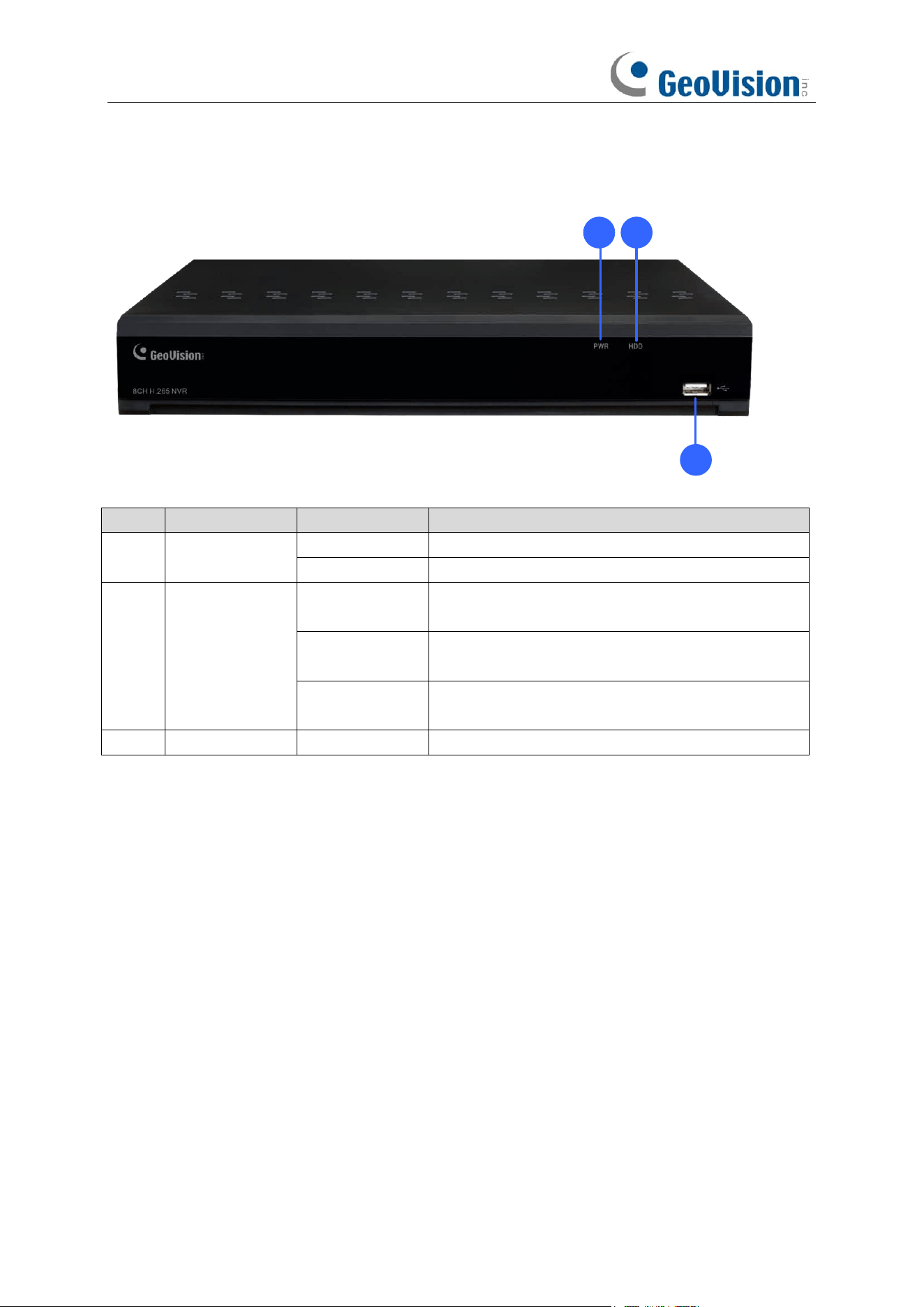
1.5 GV-RNVRL810-P Front View
1 2
3
No.
Item
Status
Description
1.
Power LED
Solid on
The device is operating properly.
Not lit
The device is shut down or not powered on.
2.
HDD LED
Lit red
The hard disk is operating properly and no data is
read or written.
Flash red
The hard disk is operating properly and there is
data read or written.
Not lit
The hard disk cannot be detected or the hard disk
is faulty.
3.
USB Port
Connected to a mobile USB device or a mouse.
6
1.6 GV-RNVRL810-P Rear View
1 2
3
4
5
76
8 9 10
12
13
11
14
No.
Item
Description
1.
Power Port
Connect the attached power supply.
2.
Alarm input interface
Connected to alarm input devices.
3.
Alarm output interface
Connected to alarm output devices.
4.
RS-485 interface
Connected to a speed dome camera.
5.
Power switch
Used to power on/off the device.
6.
Audio input
Connected to an analog audio input device.
7.
Audio output
Connected to an analog audio output device.
8.
VGA
Connected to a VGA monitor.
9.
HDMI
Output interface of the device, supporting output with up to 4K
resolution.
10.
Reset button
Used to restore the factory settings. You can press and hold the
button for 10 seconds to make the system automatically restore
the factory settings, and the buzzer rings four times at the same
time.
11.
USB Port
Connect a USB device, such as USB mouse and USB flash disk.
12.
e-SATA
Connected to an external storage device. A maximum of one
hard disk is supported.
13.
LAN
Gigabit network interface for connecting network cables.
14.
Megabit PoE ports
Connected to cameras, delivering power and network
connection to the cameras.
7
Chapter 2 NVR Installation & Connection
2.1 HDD Installation
The number of 3.5" SATA hard drives that the NVR supports varies depending on the model. The
following procedures are for reference only. The practical operation may be different depending on
the NVR you purchased.
Caution:
Do not install or remove the hard disk drive while the power is turned on.
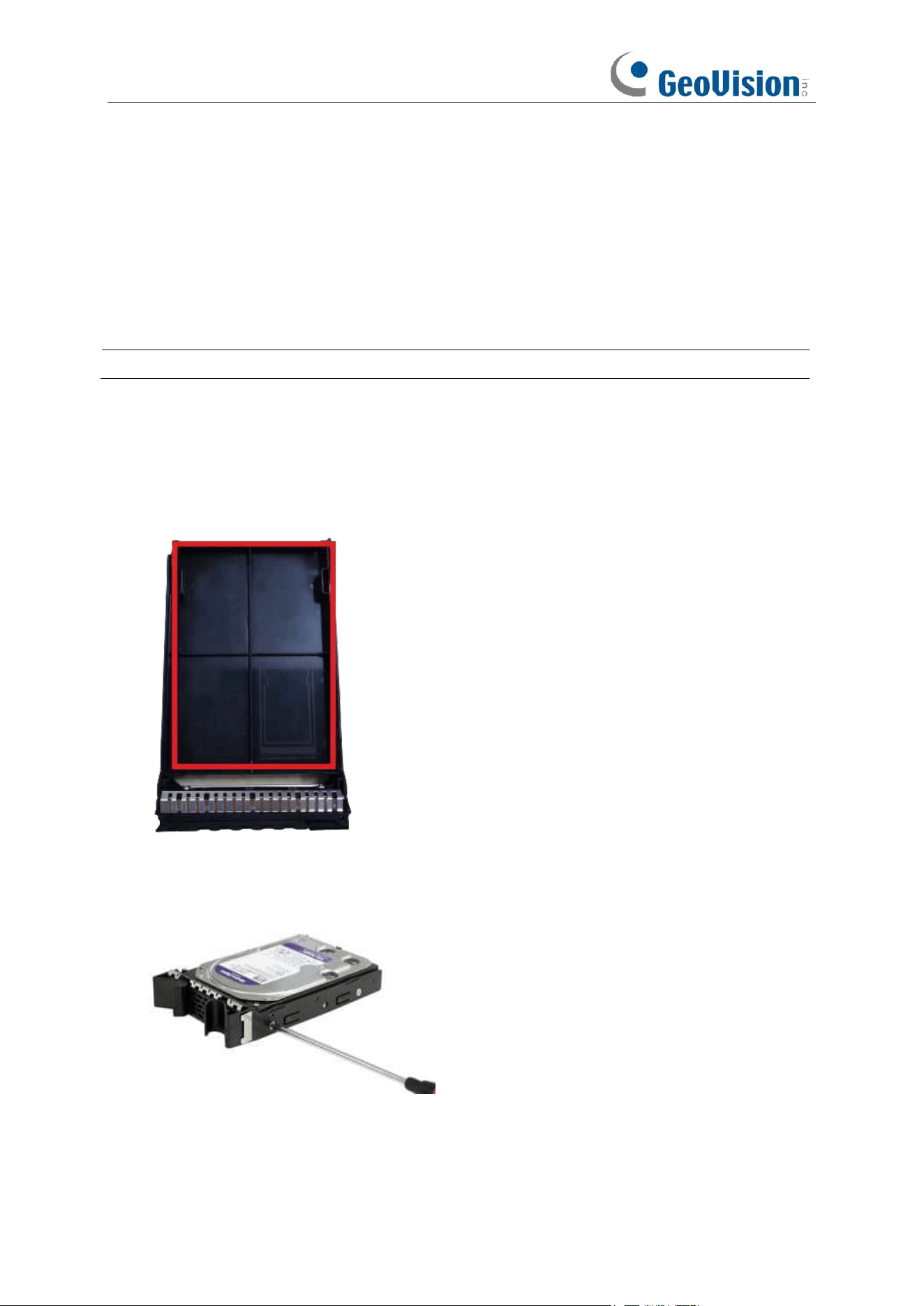
2.1.1 GV-RNVR256G0-N
1. Remove the placeholder from the ejector lever.
2. Install the ejector lever of the hard drive
Use screws to fix the hard drive on the ejector lever. You can distinguish between the left side
and the right side in accordance with the indicators on the ejector lever.
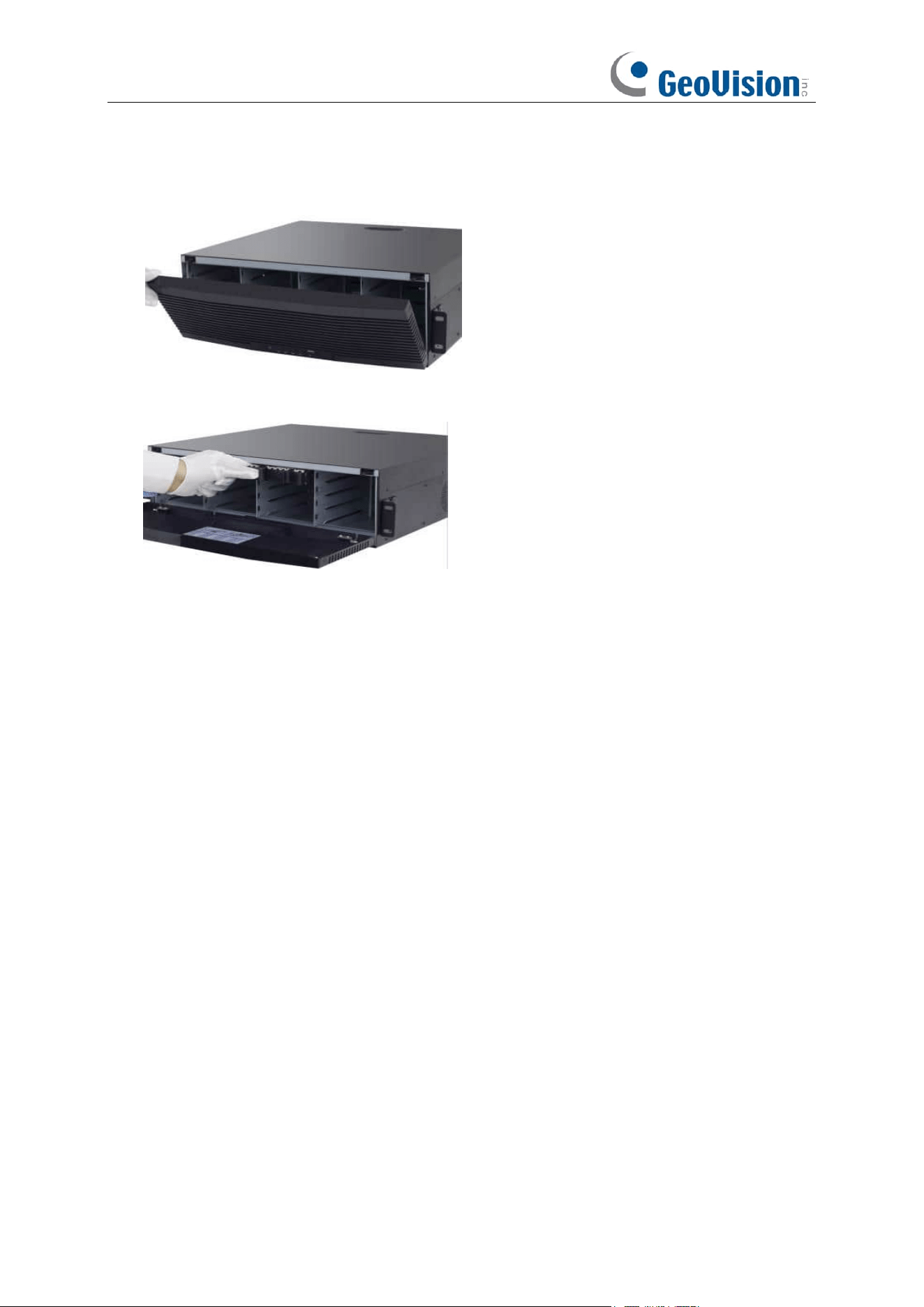
8
3. Open the front panel
Press the buckles on the two sides on the upper part of the front panel and pull the front panel
outwards.
4. Insert the hard drive
Align the hard drive slot and insert the hard drive gently and smoothly.
5. Buckle up the hard drive and close the front panel
Push in the hard drive until you hear a click. After the hard drive is installed, close the front
panel.
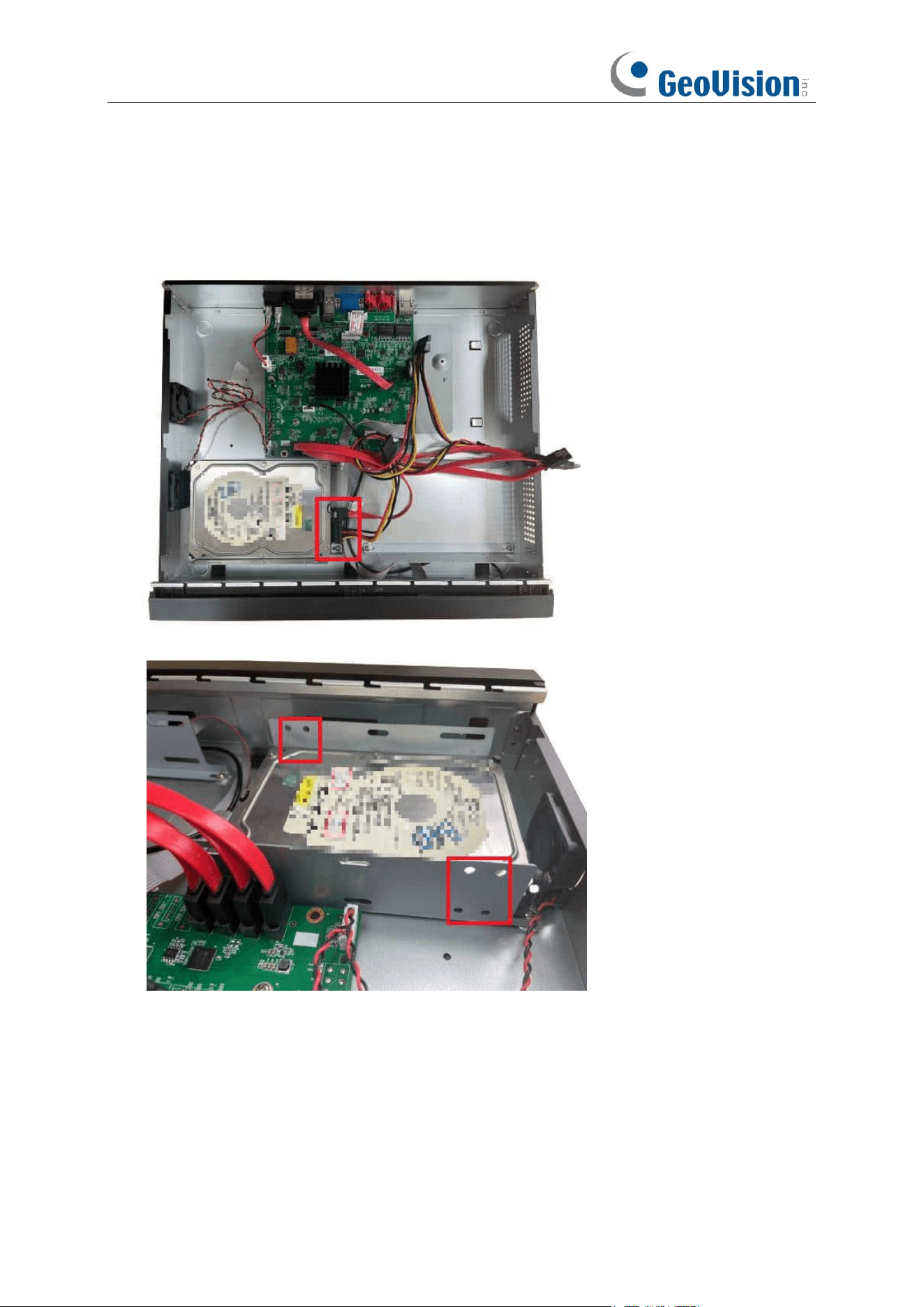
9
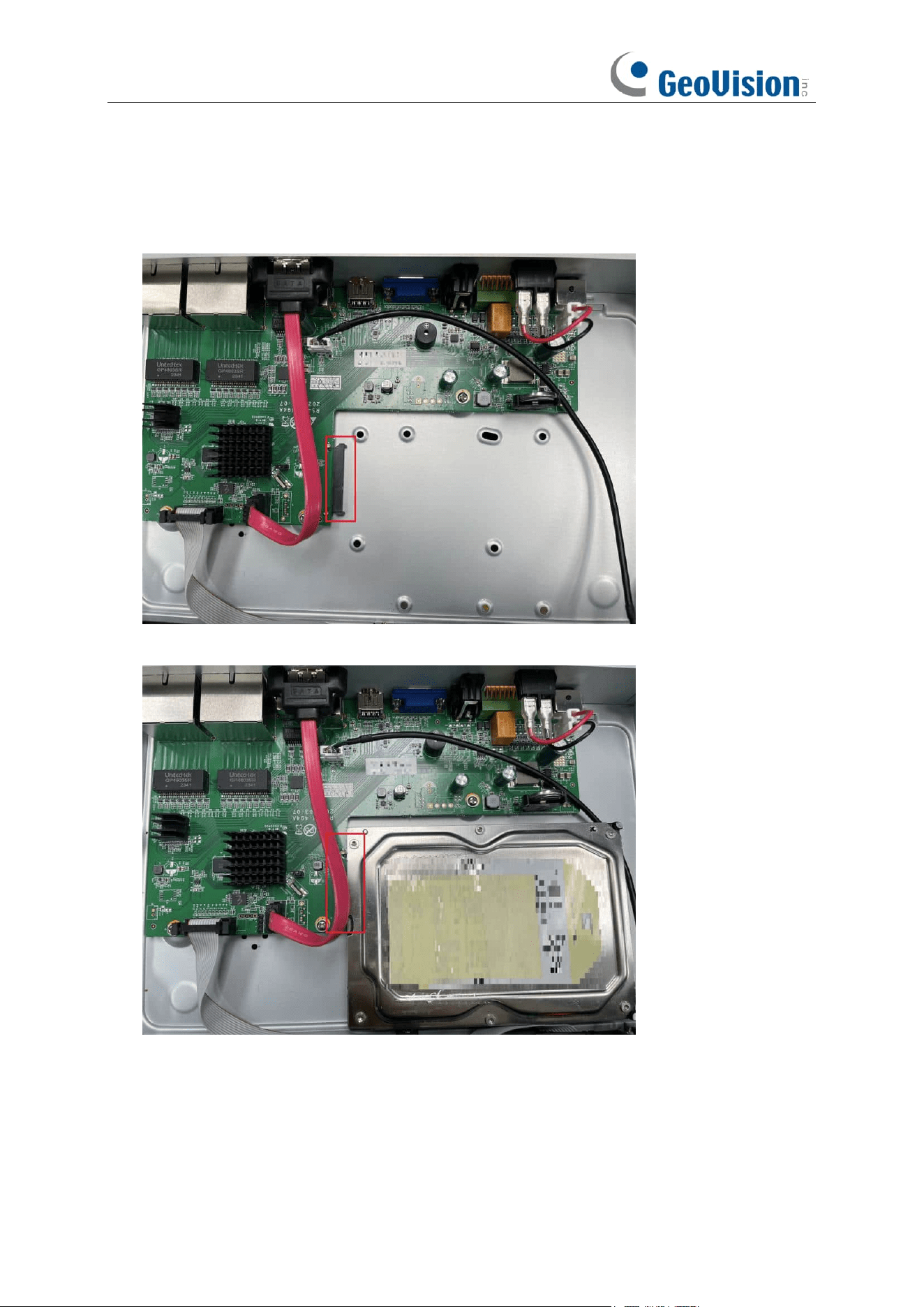
2.1.2 GV-RNVR3240-N
1. Connect the data and power cables to the hard disk drives and place them on the NVR case.
Up to 2 hard disk drives can fit in one tray on each side.
2. Secure the hard disk drives to the NVR with screws.
10
2.1.3 GV-RNVRL810-P
1. Align the hard drive with the power and data connectors indicated below.
2. Mount the hard drive to finish the installation.
11
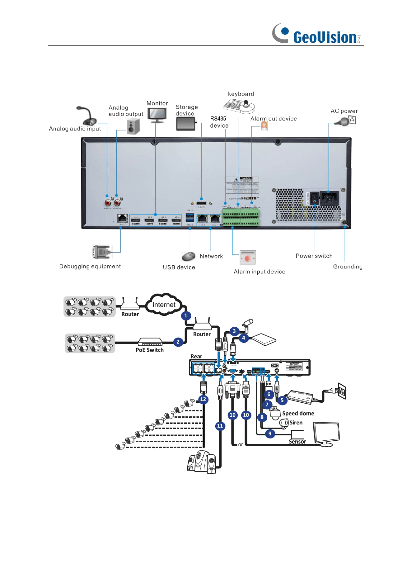
2.2
Connection Diagram
1. You can connect to other IP cameras remotely over the Internet.
2. Connect a CAT.5E or higher RJ45 Ethernet cable for local connectivity. You can connect to
other IP cameras through your local network.
3. Two-way voice conversation with the remote PC.
12
4. Connect an external hard disk drive to backup files stored on the NVR.
5. Connect the included power cable.
6. Use the USB flash disk for backup, camera, or system upgrade.
7. Connect a RS-485 device such as a speed dome camera.
8. Connect an external alarm output device such as siren.
9. Connect external alarm sensors.
10. Connect the video output of the NVR to the TV or monitor via HDMI or VGA connection.
11. Connect speakers if you want to listen to the live audio sound or audio playback from the
NVR.
12. Connect the PoE IP cameras. It may take up to 1 minute for the cameras to start transmitting
video to the NVR.
Note:
Above connection diagram is for illustration purpose only. The interfaces in your actual
product may vary with models.
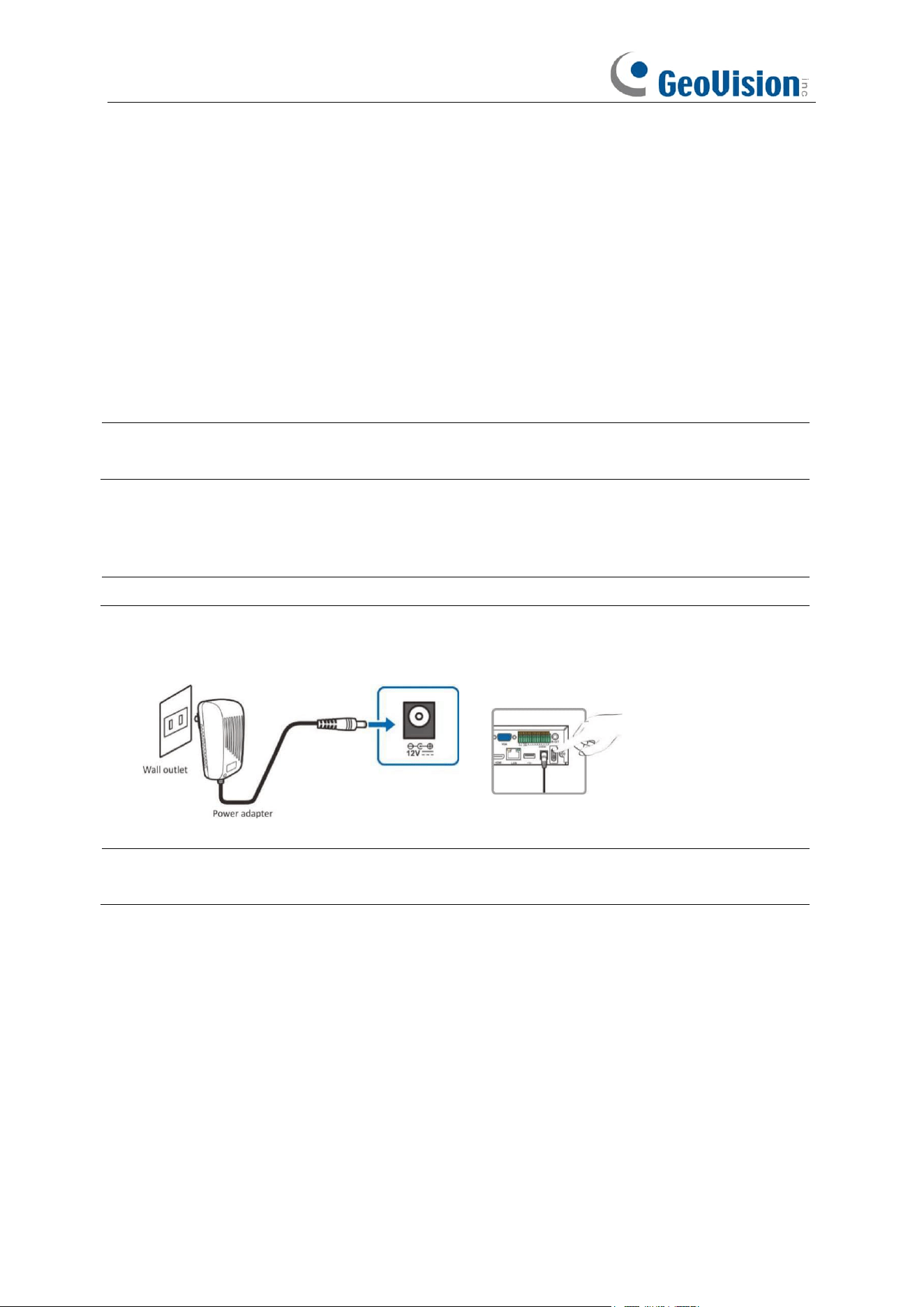
2.3 Power Supply Connection
Caution:
Only use the supplied power adapter that comes with the NVR.
Connect one end of the power adapter to the power connector on the back of the NVR. Plug the other
end of the power adapter into the wall outlet. And press the Power Switch to turn on the power.
Note:
Above connection diagram is for illustration purpose only. The interfaces in your actual
product may vary with models.
13
Chapter 3 NVR Common Operations
3.1 Using the Supplied Mouse
1.
Left Button:
o
Click to select menu options.
o
During live viewing in split-screen view, double-click on a
channel
to view it in full-screen.
Double-click the
channel
again to return to split-screen viewing.
o
Click
upon a channel on Live Viewing screen to open Camera Quick Toolbar.
o
Click and hold to drag sliders and scales on menu mode
2.
Right Button:
o
Click once to open the Taskbar on the Live Viewing screen. View Taskbar on 4.2.2 Taskbar
o
In menus, click to go back / close menus.
3.
Scroll Wheel:
o
In menus, scroll to move up / down through the menu content.
o
While hovering over the volume control wheel, scroll to turn system volume up / down.
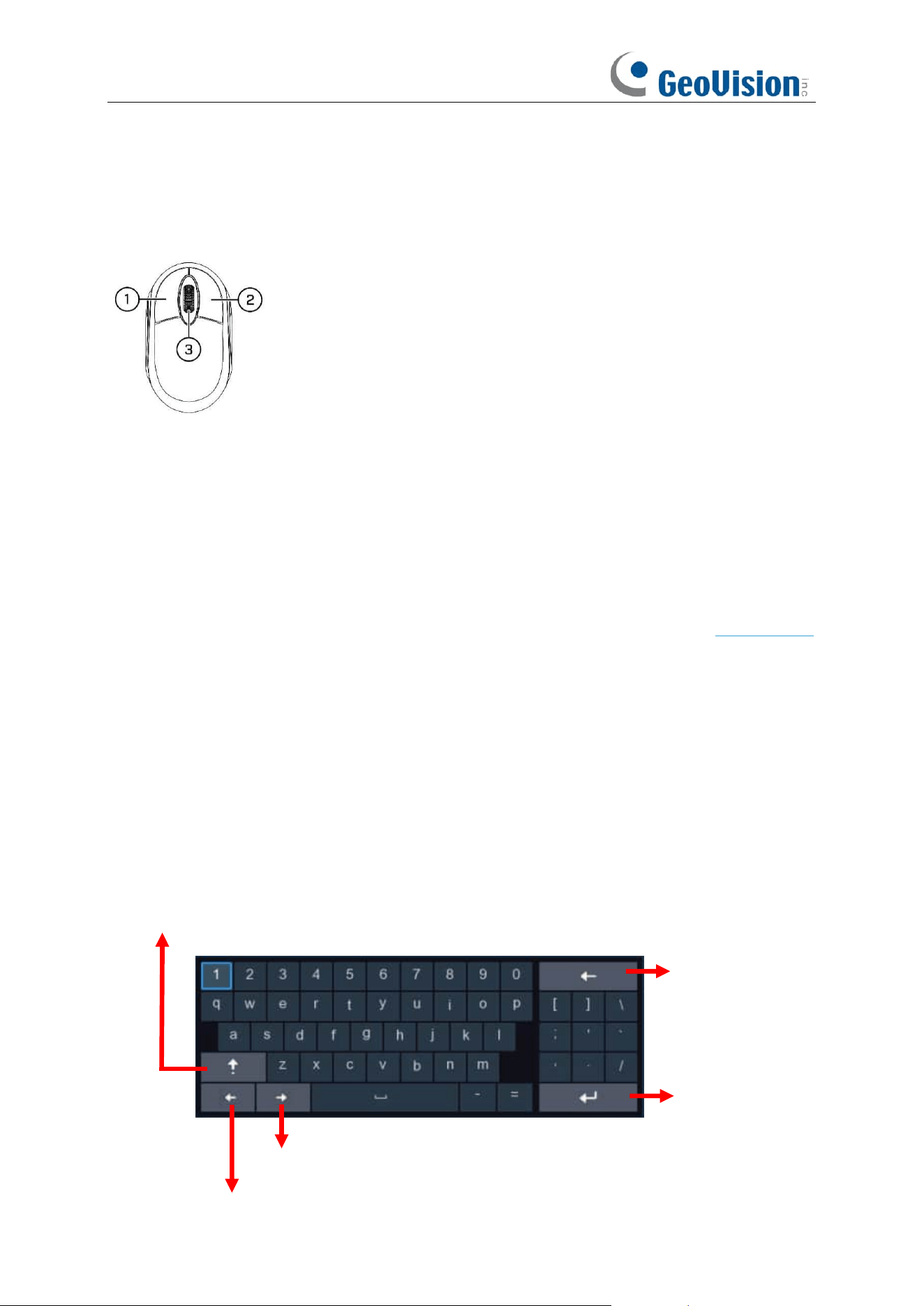
3.2 Using the Virtual Keyboard
You will see the virtual keyboard automatically on the screen when you need to enter data
Click to delete a
character
Click to finish
Click to toggle the keyboard to
upper case and more punctuation
Move the cursor to left
Move the cursor to right
14
3.3 Password
3.3.1 Password Generation
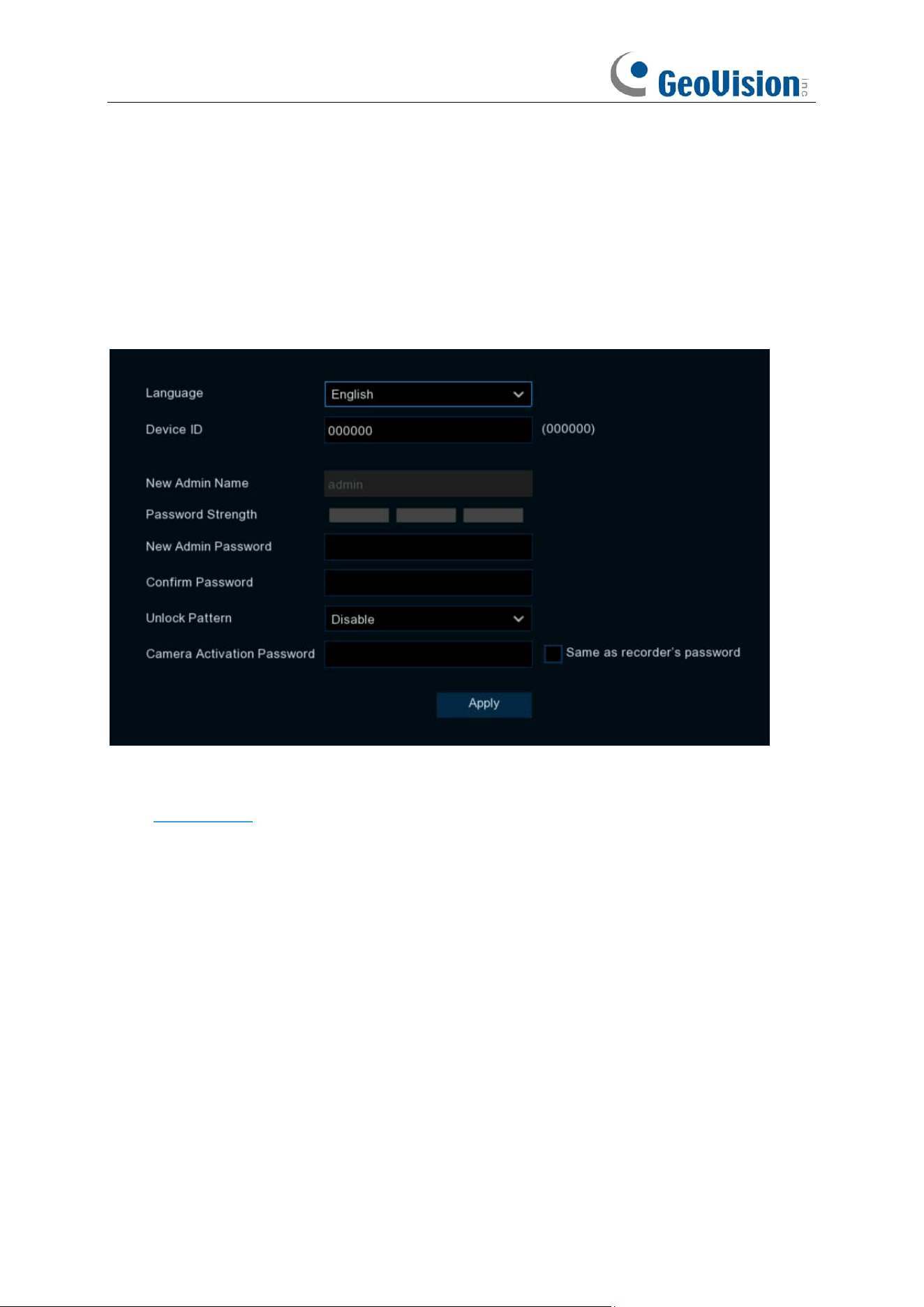
For the first time when you run the NVR, you must be required to set your own password
immediately in order to protect your privacy. Be sure to record your username and password and
save them in a secure place.
Language:
Choose an OSD language.
Device ID:
Input the device ID in the parentheses. Default ID is 000000. View more about Device
ID on 5.7.1 General.
New Admin name:
To set your own administrator name.
New Admin Password:
To set your own password. The password must be a combination of 8
characters.
Confirm Password:
Enter your own password again.
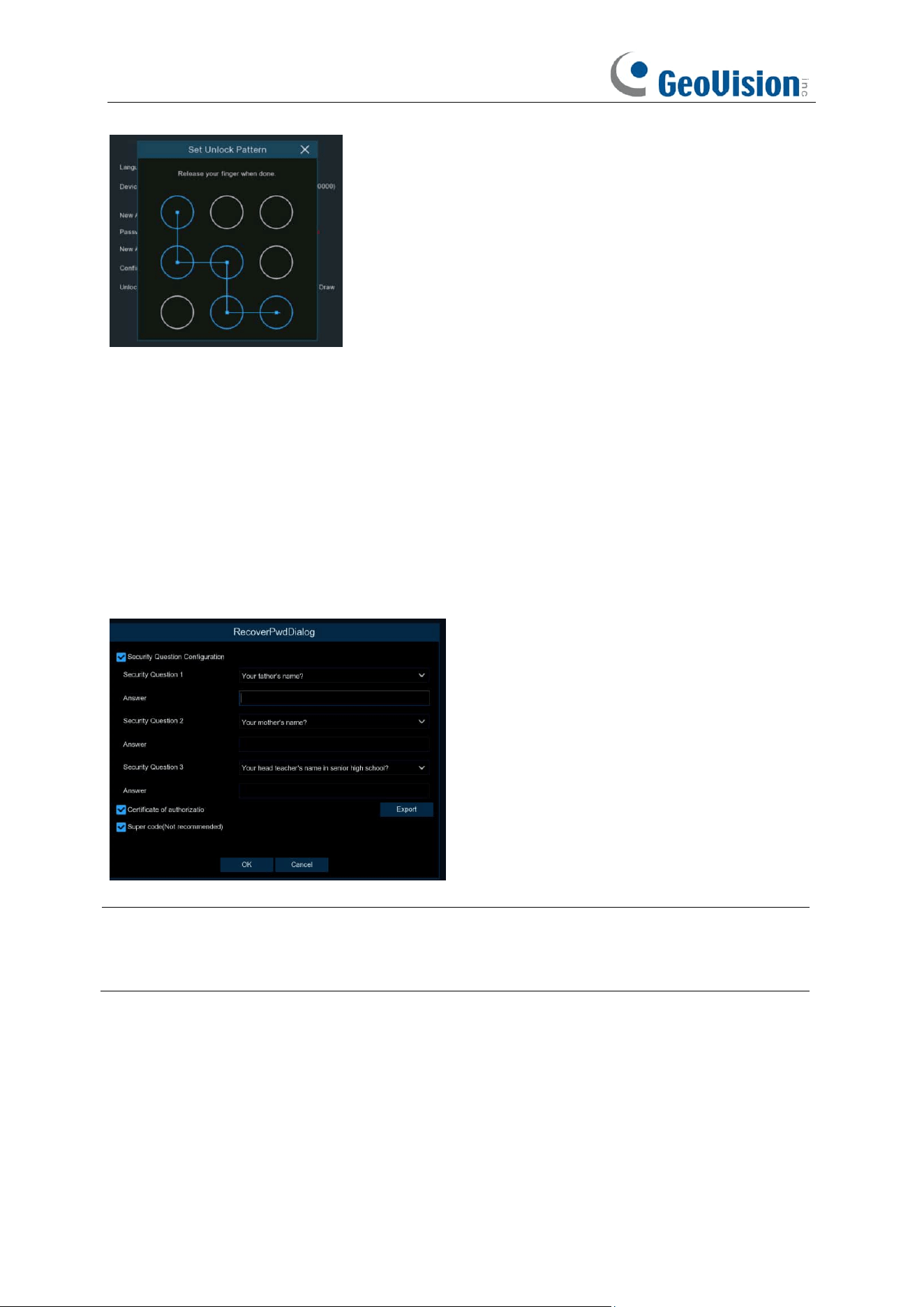
Unlock Pattern:
Select
Enable
to draw your pattern lock.
Camera Activation Password:
This password will be used to activate an inactivated camera that
is connected to the NVR. When
Same as recorder's password
is unchecked, user-defined
camera activation passwords are supported. When
Same as recorder's password
is checked,
the device's login password will be automatically applied as the camera activation password.
Click Apply to confirm your settings. The system will require to set the password recovery
questions in case you forget the password.
15
Tick the box of Security Question Configuration, and then choose 3 questions and input your
answer to each question.
If you tick the box of Certificate of Authorization, you need to click the Export button to save a
secret key to your USB flash drive. It will help to reset the password with the secret key in future.
Super code: It is a backup method to reset your password. If you enable this function, a
temporary & time-bound super code will be able to generated. It is allowed to login the system with
the super code and create your new password. However, the super code is not recommended to
be enabled for safety reason.
Caution:
Make sure to set at least one of the 3 password recovery methods in case you forget
the password. If you select
Cancel,
no password recovery methods will be available when you
forget your password. Contact our technical personnel to reset the password.
16
3.3.2 Reset Password
If you forget your password, you will be unable to login the system, reset your password with
below methods:
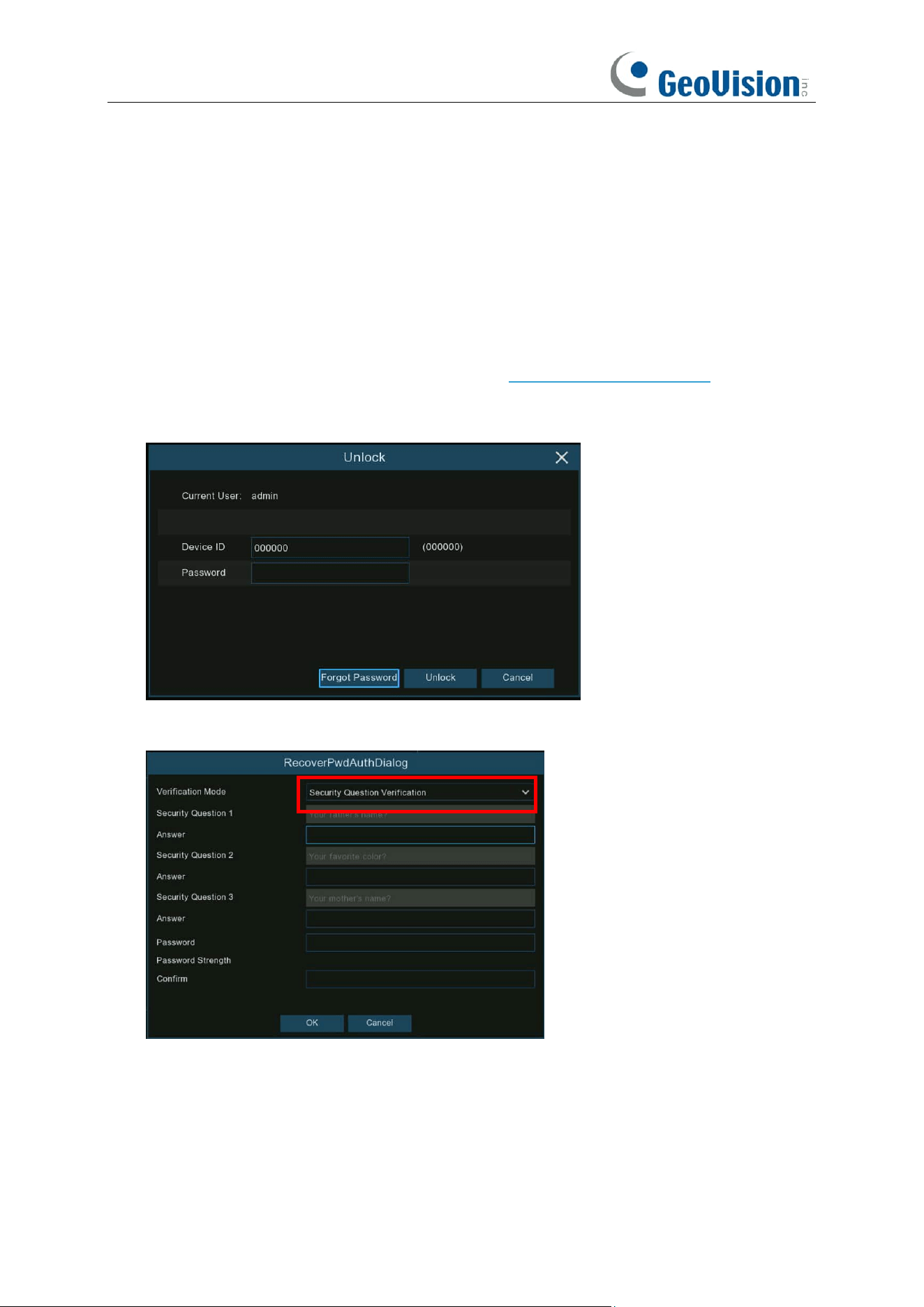
3.3.2.1 Reset with Password Recovery Questions
If you had enabled the password recovery questions in 3.3.1. Password Generation, you are able
to reset your password with security questions.
1. Click the Forgot Password button on the login window.
2. Choose Security Question Verification. Input the answer to each question and then input
new password. Click OK to activate the new password.
17
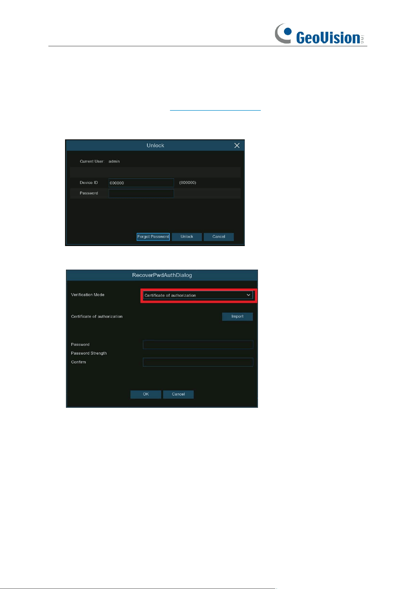
3.3.2.2 Reset with Secret Key
If you had exported the secret key in 3.3.1. Password Generation, you are able to reset your
password with secret key.
1. Click the Forgot Password button on the login window.
2. Choose Certificate of Authorization. Click Import button to load the secret key from your
USB flash drive, and then input new password. Click OK to activate the new password.
18
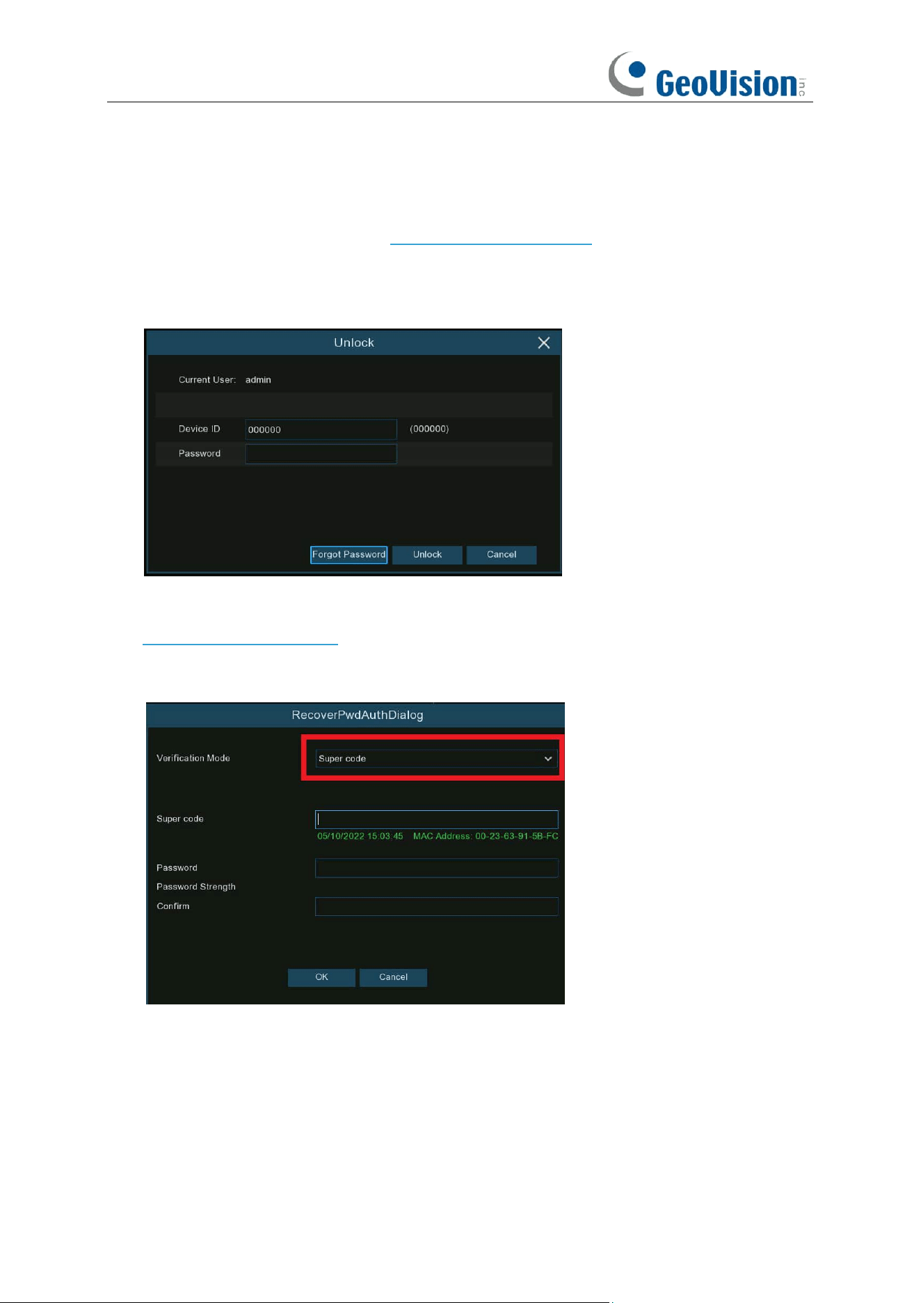
3.3.2.3 Reset with Super Code
If you had activated the Super Code in 3.3.1. Password Generation, you are able to reset your
password with super code. Contact our support team for the super code before proceeding with
the following steps.
1. Click the Forgot Password button on the login window.
2. Choose Super Code.
3. Provide the date and MAC address information to our support personnel at
support@geovision.com.tw.
4. Input the Super Code you get from the technical personnel, and input the new password.
Click OK to activate the new password.
19
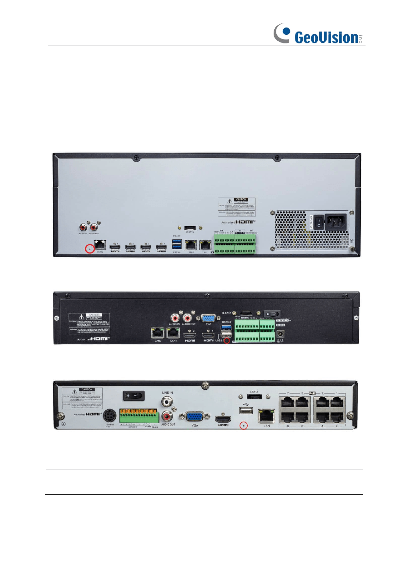
3.3.2.4 Hard Reset
If you are unable to reset the password with any one of the methods mentioned above, you can try
to hard reset your NVR.
GV-RNVR256G0-N
GV-RNVR3240-N
GV-RNVRL810-P
Press and hold for 10 seconds on the button with a small pin till the NVR beeps.
Caution: The hard reset will not only reset the password but also load all system settings to the
default values. You self-defined settings will be lost.
20
Chapter 4 NVR Starting up
4.1 Start Wizard
Startup Wizard will help configure the system and get the NVR works quickly.
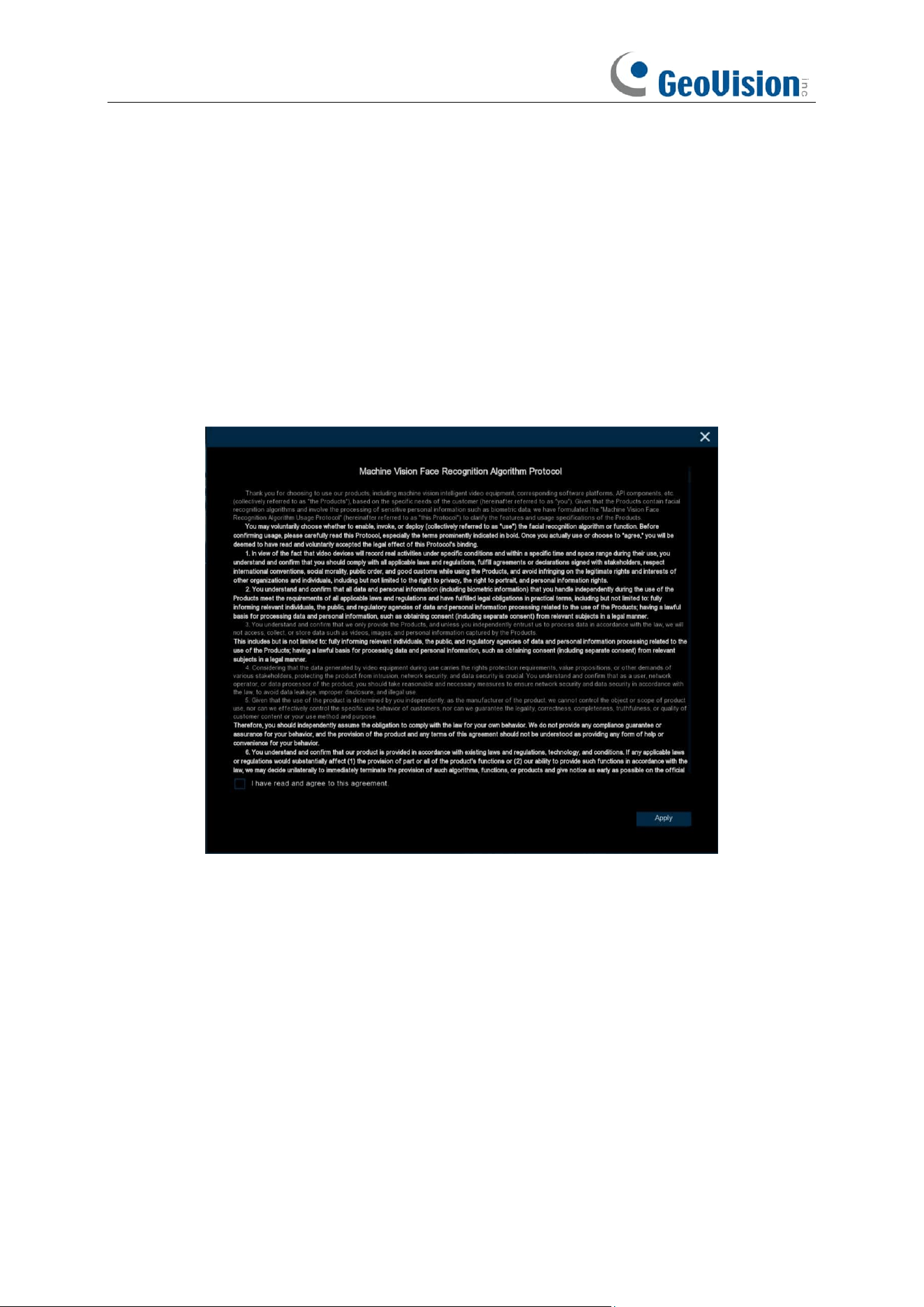
For models that support face recognition function. When you enter the system for the first time, the
machine vision face recognition algorithm agreement will pop up. Check "I have read and agree to
this agreement" and save it. When the device is connected to an AI camera that supports face
recognition, the face recognition function can be enabled. Otherwise, the face recognition function
will not be enabled.
21
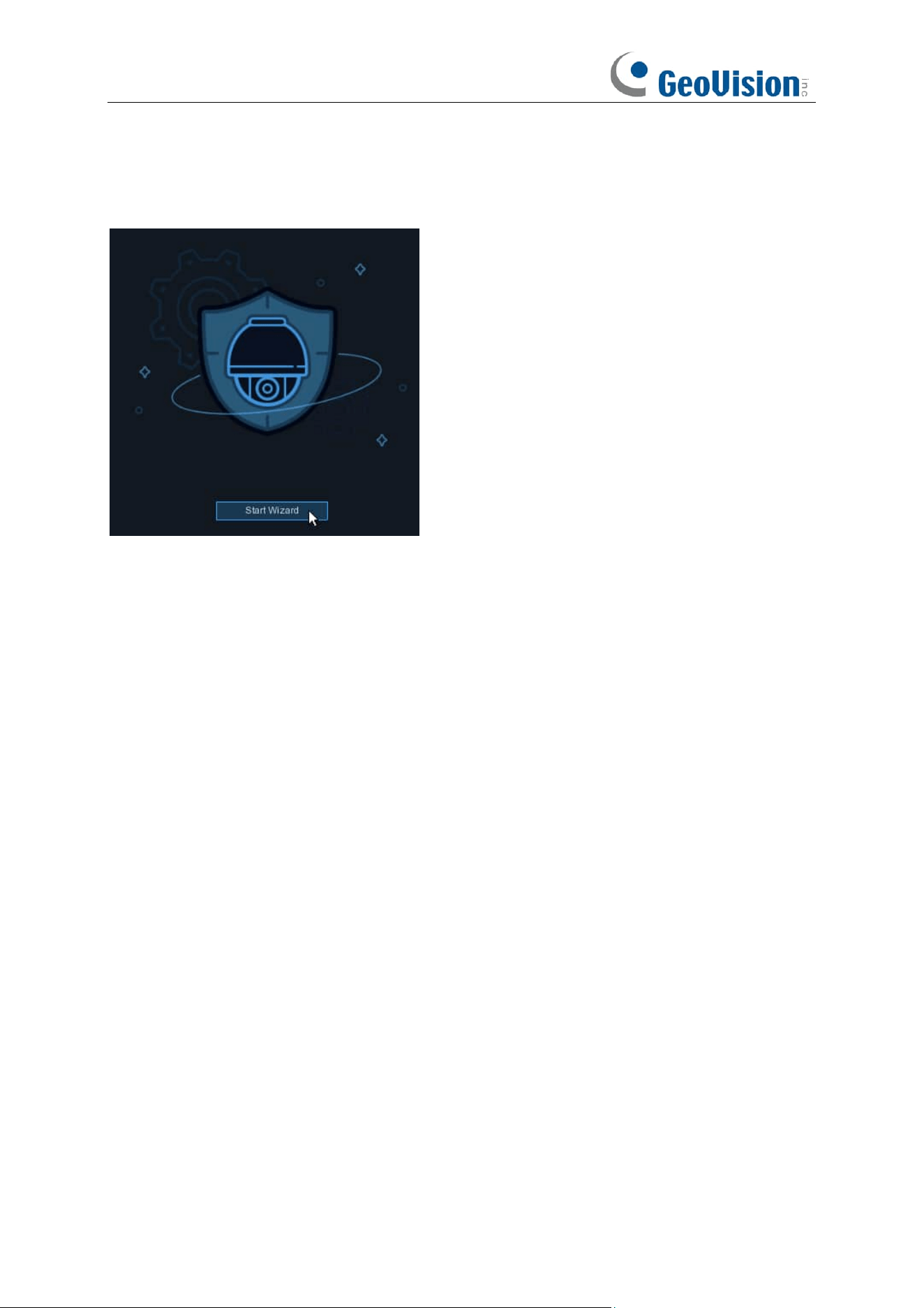
4.1.1 Start Wizard
Click the
Start Wizard
to proceed to the next step
22
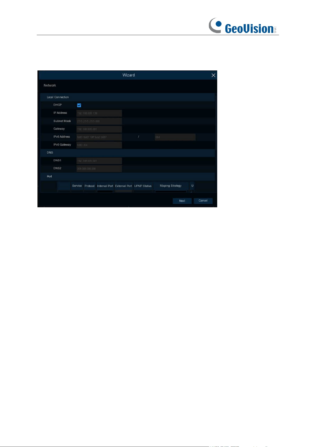
4.1.2 Network Configuration
Network Card Mode:
switch Single Address Mode or Double Address Mode, NVR will reboot after
successful switching. (Note: Models with POE only support Double Address Mode)
Single Address Mode:
Binds both ports to a single IP address. Selecting this mode can increase
the bandwidth and form a redundant array of network cards, load sharing, one of the network port
fails, the other network port immediately take over the load, the service will not be interrupted.
Double Address Mode:
The two network ports are set up with different IP addresses, gateways,
etc., and work independently of each other. The LAN port accessing the external network should
be set as the default route.
Network Card Select:
Toggles the display of network parameter information of LAN1 or LAN2,
this option is grayed out and unavailable in single NIC mode.
DHCP IPv4:
If you connect to a router that allows DHCP, check this box, the router will
automatically assign all IPv4 protocol network parameters to the NVR, after unchecking the box, IP,
Subnet Mask, Gateway, DNS will be automatically changed back to the parameters that were set
when you unchecked the box the last time (Note: Currently the program does not support DHCP
IPv6)
If you connect to a router allows to use DHCP, check the
DHCP
box. The router will assign
automatically all the network parameters for your NVR. Unless the network is manually addressed
below parameters:
IP Address
: The IP address identifies the NVR in the network. It consists of four groups of
numbers between 0 to 255, separated by periods. For example, “192.168.001.100”.

23
Subnet Mask
: Subnet mask is a network parameter which defines a range of IP addresses that
can be used in a network. If IP address is like a street where you live then subnet mask is like a
neighborhood. The subnet address also consists of four groups of numbers, separated by periods.
For example, “255.255.000.000”.
Gateway
: This address allows the NVR to access the Internet. The format of the
Gateway
address is the same as the
IP Address
. For example, “192.168.001.001”.
IPv6 Address:
Input the IPv6 address you got from your ISP. It consists of eight groups of
numbers between 0 and FFFF separated by colons.
For example, "ABCD:EF01:2345:6789:ABCD:EF01:2345:6789"
Subnet Prefix Length:
subnet prefix length.
IPv6 Gateway:
IPv6 gateway IP address of the network where the device is located.
DNS1/DNS2
: DNS1 is the primary DNS server and DNS2 is a backup DNS server. Usually, it
should be enough just to enter the DNS1 server address.
Default Route:
In dual-address mode, set the LAN port accessing the external network as the
default route. (Note: This option is grayed out in Single Address Mode)
24
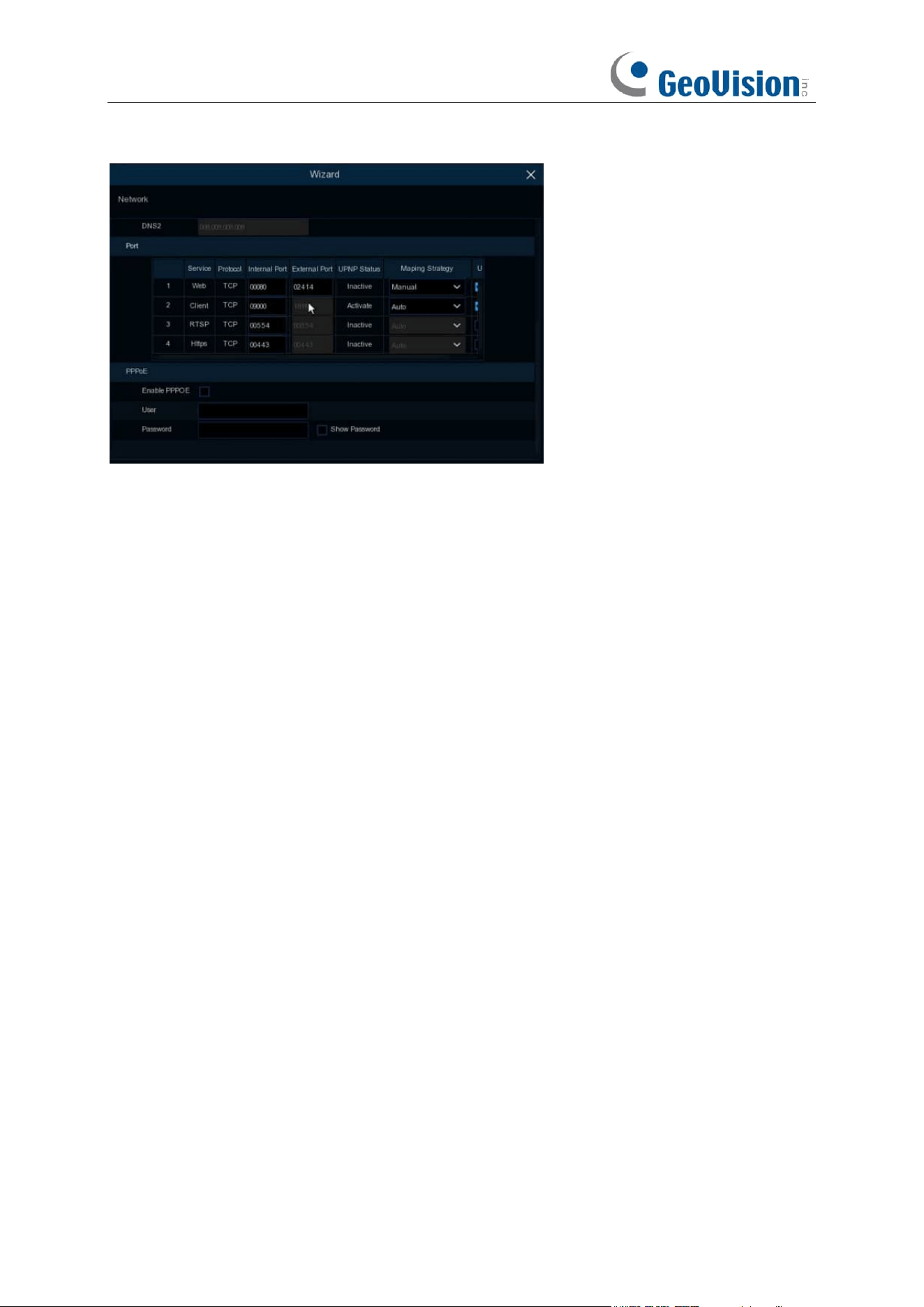
Port
Web:
This is the port that you will use to log in remotely to the NVR (e.g. using the Web Client). If
the default port 80 is already taken by other applications, please change it.
Client:
This is the port that the NVR will use to send information through (e.g. using the mobile
app). If the default port 9000 is already taken by other applications, please change it.
RTSP:
This is the port that the NVR will be allowed to transmit real-time streaming to other device
(e.g. using a streaming Media player).
Https:
This is the port that you will use to log in remotely to the NVR by browsers with https
protocol.
Internal Port:
Used for LAN connection.
External Port:
Used for WAN / Internet connection.
UPNP:
If you want to log in remotely to the NVR using Web Client, you need to complete the port
forwarding in your router. Enable this option if your router supports the UPnP. In this case, you do
not need to configure manually port forwarding on your router. If your router does not support
UPnP, make sure the port forwarding is completed manually in your router.
Mapping Strategy:
If you want the port randomly distributed by the router UPNP server, choose
“
Auto
”; If you want to manually forwarded the port, choose “
Manual
”.
PPPoE:
This is a protocol that allows the NVR to connect to the network directly via a DSL
modem.
Enable PPPOE:
The NVR will reboot to activate the PPPoE setting after it is enabled.
PPPOE Network Card Select:
Select the LAN port for dial-up access. (Note: This option is not
shown in single NIC mode)
User:
PPPOE user name.
Password:
PPPOE password.
25
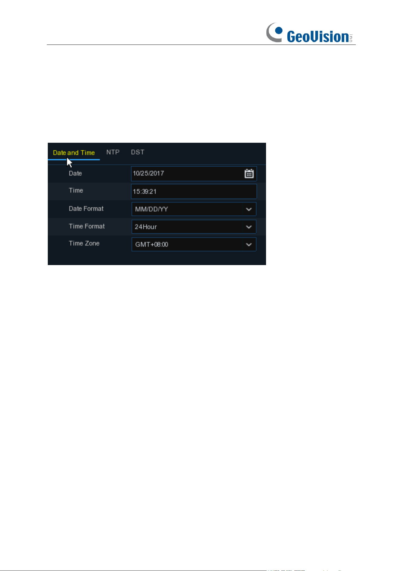
4.1.3 Date/Time
This menu allows you to configure the Date, Time, Date Format, Time Format, Time Zone, NTP
and DST.
Date and Time
Click on the calendar icon to set the current system date.
Date:
Click on the calendar icon to set the system date.
Time:
Click to set the system time.
Date Format:
Choose from the dropdown menu to set preferred date format.
Time Format:
Choose time format between 24Hour and 12Hour.
Time Zone:
Set the correct time zone.
26
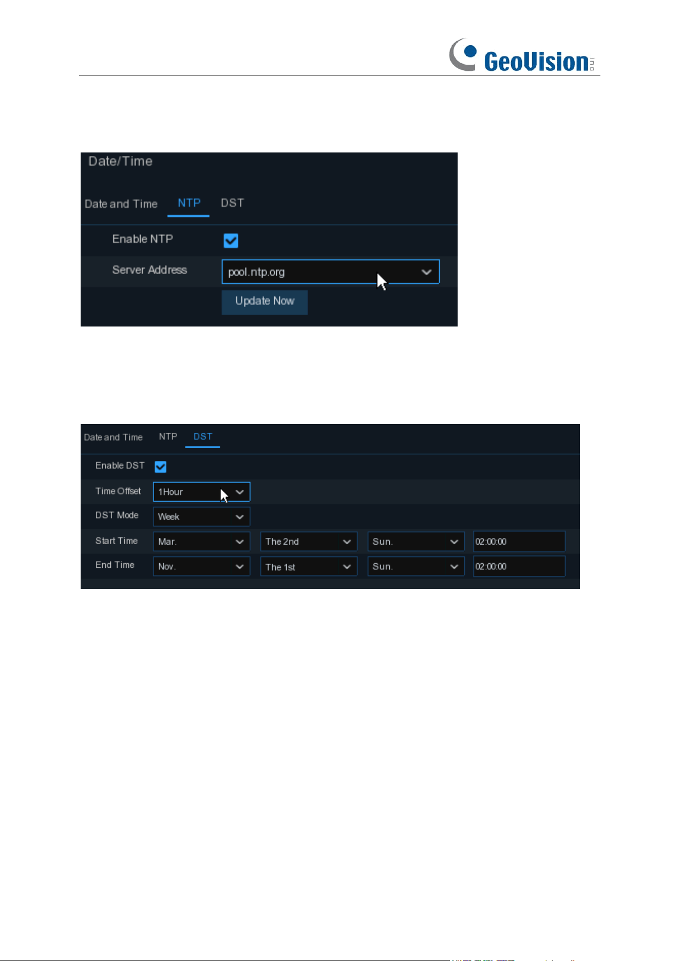
NTP
NTP stands for Network Time Protocol. This feature allows you to synchronize the date and time
automatically on the NVR over Internet. Therefore, the NVR needs to be connected to the Internet.
Check the “
NTP
” box, and select the NTP server.
DST
DST stands for Daylight Savings Time.
DST
: Enable if Daylight Saving Time (DST) is observed in your region
Time Offset
: Select the amount of time to offset for DST
Time Mode
: Choose to set the daylight-saving time in weeks or in days
Start Time/End Time
: Set the start time and end time for daylight saving
27
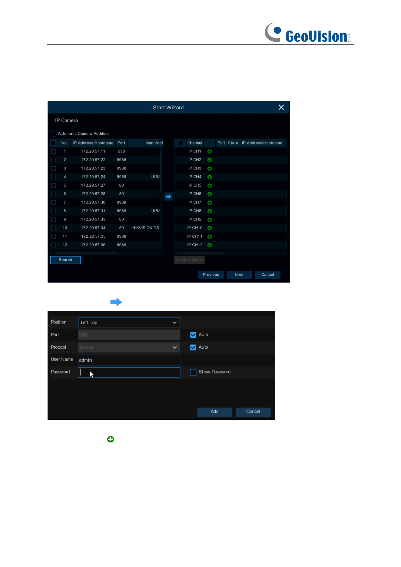
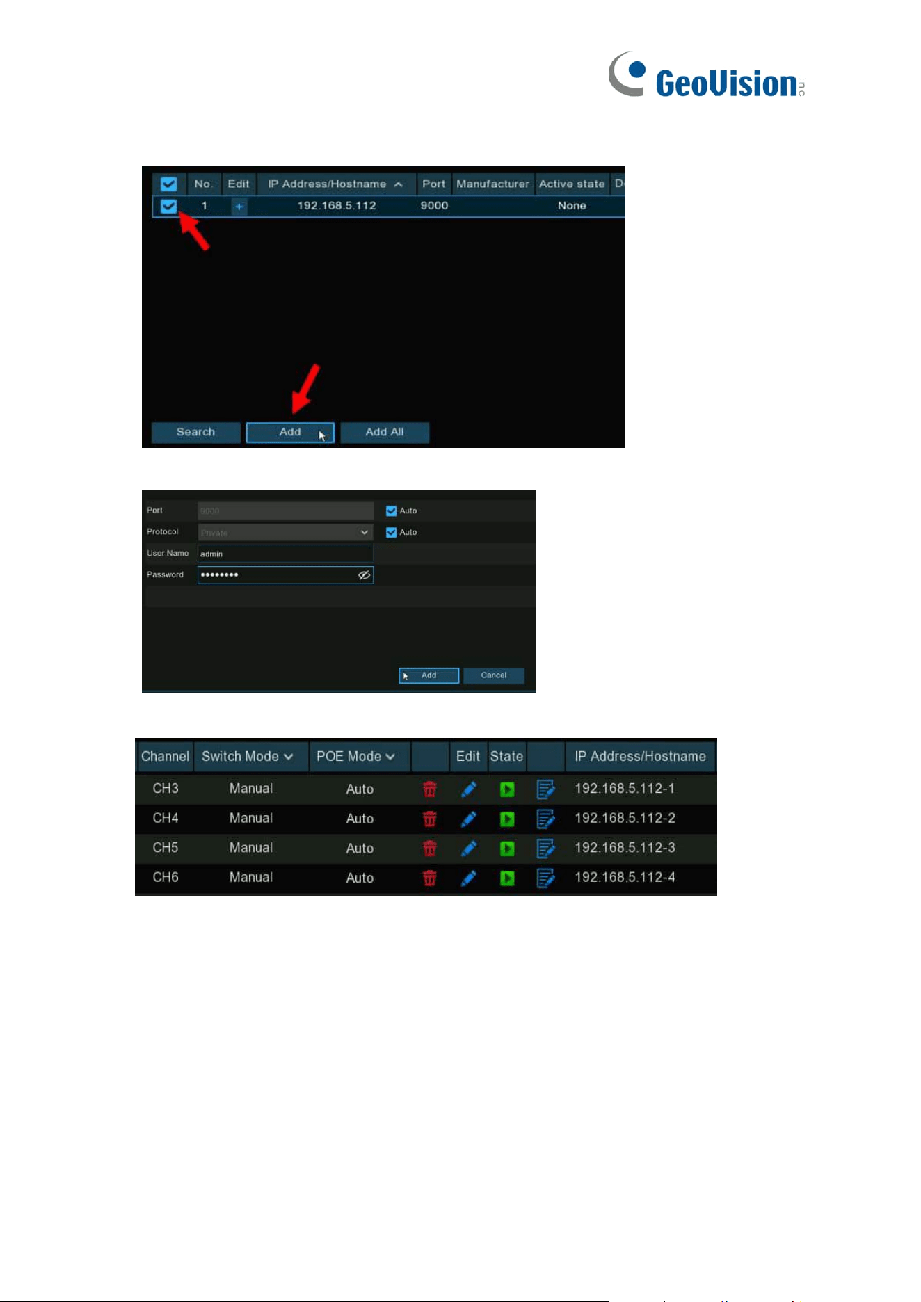
4.1.4 IP Camera
This menu allows you to add IP cameras to the NVR.
Click
Search
to search IP cameras in the same network. Choose the IP camera(s) you want to
add, and then click icon to add to the NVR.
Enter the camera’s user name & password to add the camera(s).
You can also click button to add individual IP camera to a single channel.
28
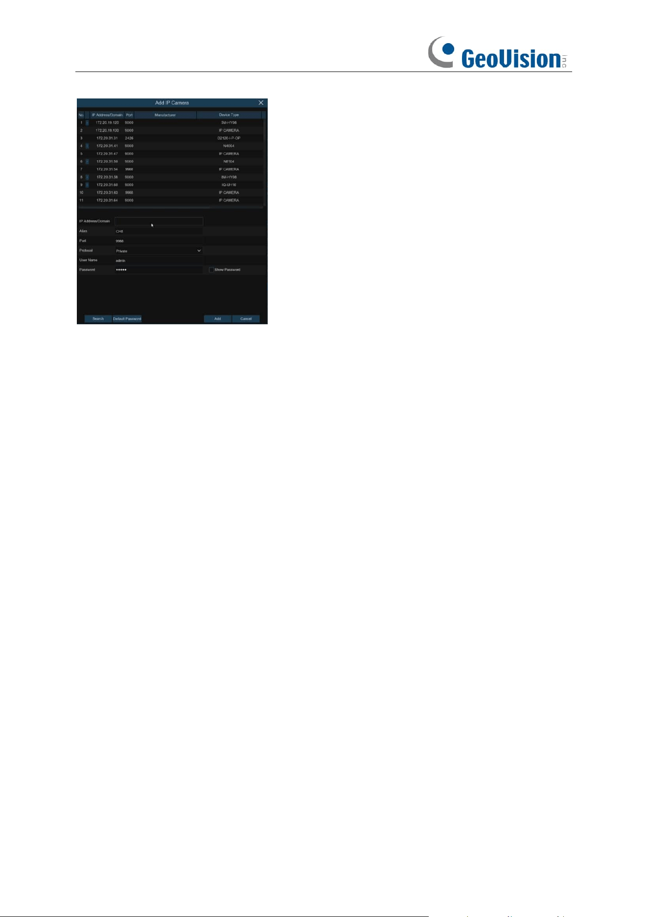
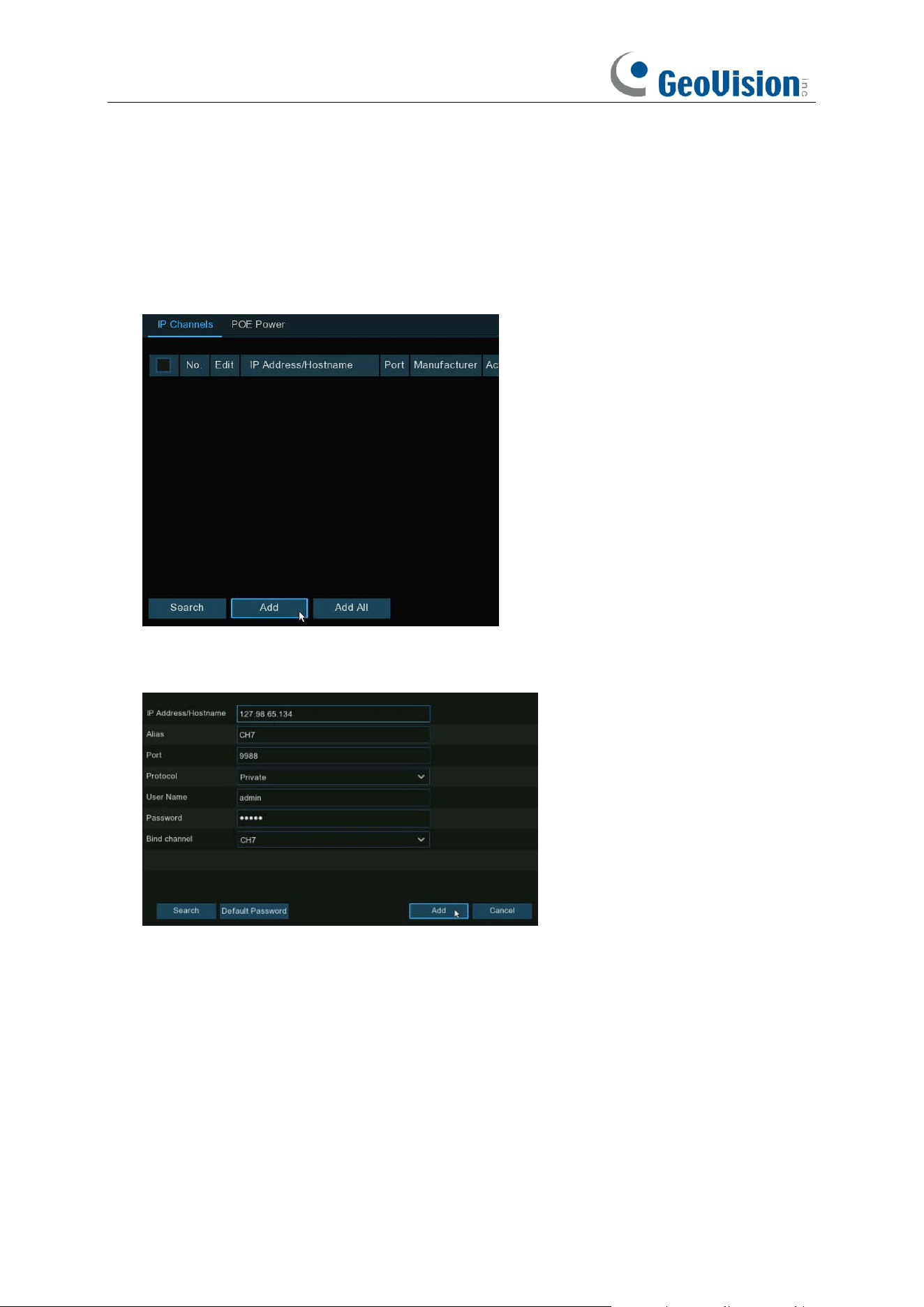
Click
Search
button to search IP cameras, and then click one of the IP cameras in the device list.
IP Address/Domain:
IP address or domain name of the IP camera
Alias:
Name of the IP camera
Position:
Position to display the camera name on the screen.
Port:
Port of the IP camera. It is set to 80 by default. Modify it if necessary.
Protocol:
Choose the protocol of the IP camera from the dropdown menu
⚫ Select
Onvif
for GV-IP cameras
⚫ Select
Private
for GV-RBL5800 / RBL5811 / REB5800 / RFER12700
⚫ Select
RTSP
, and type the commands as shown below:
Main Stream: rtsp://IP address:port/rtsp/streaming?channel=xx&subtype=0
Sub Stream: rtsp://IP address:port/rtsp/streaming?channel=xx&subtype=1
User Name:
User Name of the IP camera
Password:
Password of the IP camera
Bind channel:
Choose a channel of the NVR you want to attach to
Automatic Camera Addition:
Enable this function for the device to automatically add cameras to
the channels where cameras are not added.
29
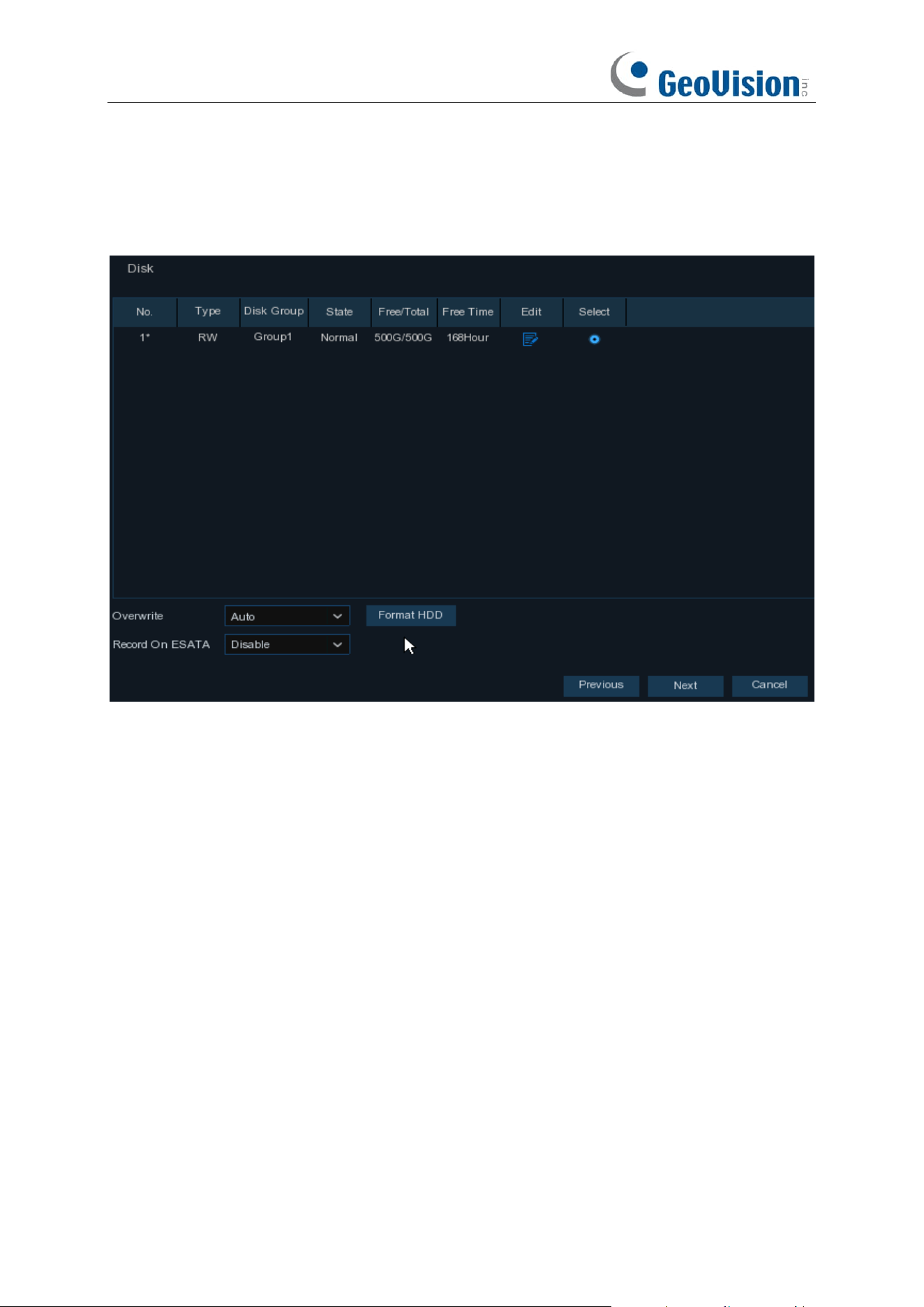
4.1.5 Disk
If the HDD is installed in the NVR for the first time, it must be formatted. Select the HDD and then
click
Format HDD
button to format the HDD.
Overwrite
: Use this option to overwrite the old recordings on the HDD when the HDD is full. For
example, if you choose the option 7 days then only the last 7 days recordings are kept on the HDD.
To prevent overwriting any old recordings, select Disable. If you have disabled this function, check
the HDD status regularly, to make sure the HDD is not full.
Add NAS HDD:
To add your NAS disk.
Record On ESATA
: If your NVR comes with an e-SATA port on the rear panel, you can enable to
record the video to e-SATA HDD.
30
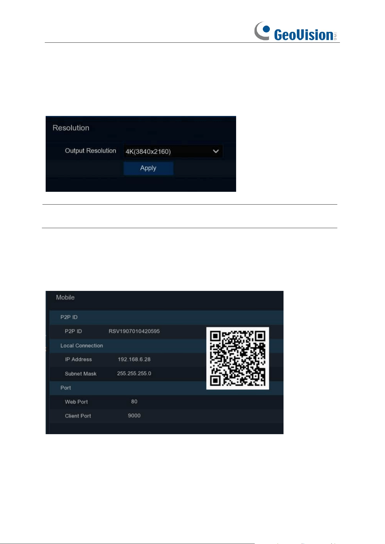
4.1.6 Resolution
Choose an output resolution matches to your monitor. The NVR supports to adjust the output
resolution automatically to match the best resolution of your monitor when the system is starting
up.
Note: If you connect to a 4K / 8K HDMI monitor, you can choose max. 4K (3840 x 2160) / 8K
(7680 × 4320) resolution.
4.1.7 Mobile
If your NVR come with a P2P ID, you can scan the QR code with your mobile app to view the NVR
remotely.
31
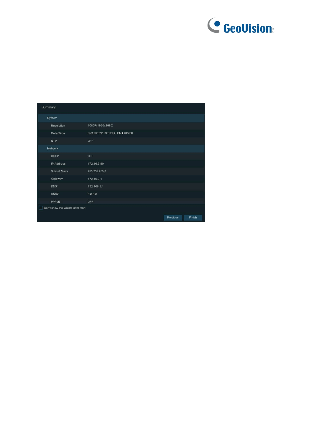
4.1.8 Summary
You can check the system summary information you had set in the start wizard and finish the
wizard.
Tick “
Don't show this window next time
" if you don’t want to display Start Wizard when system
reboot next time. Click
Finish
button to save & exit.
32
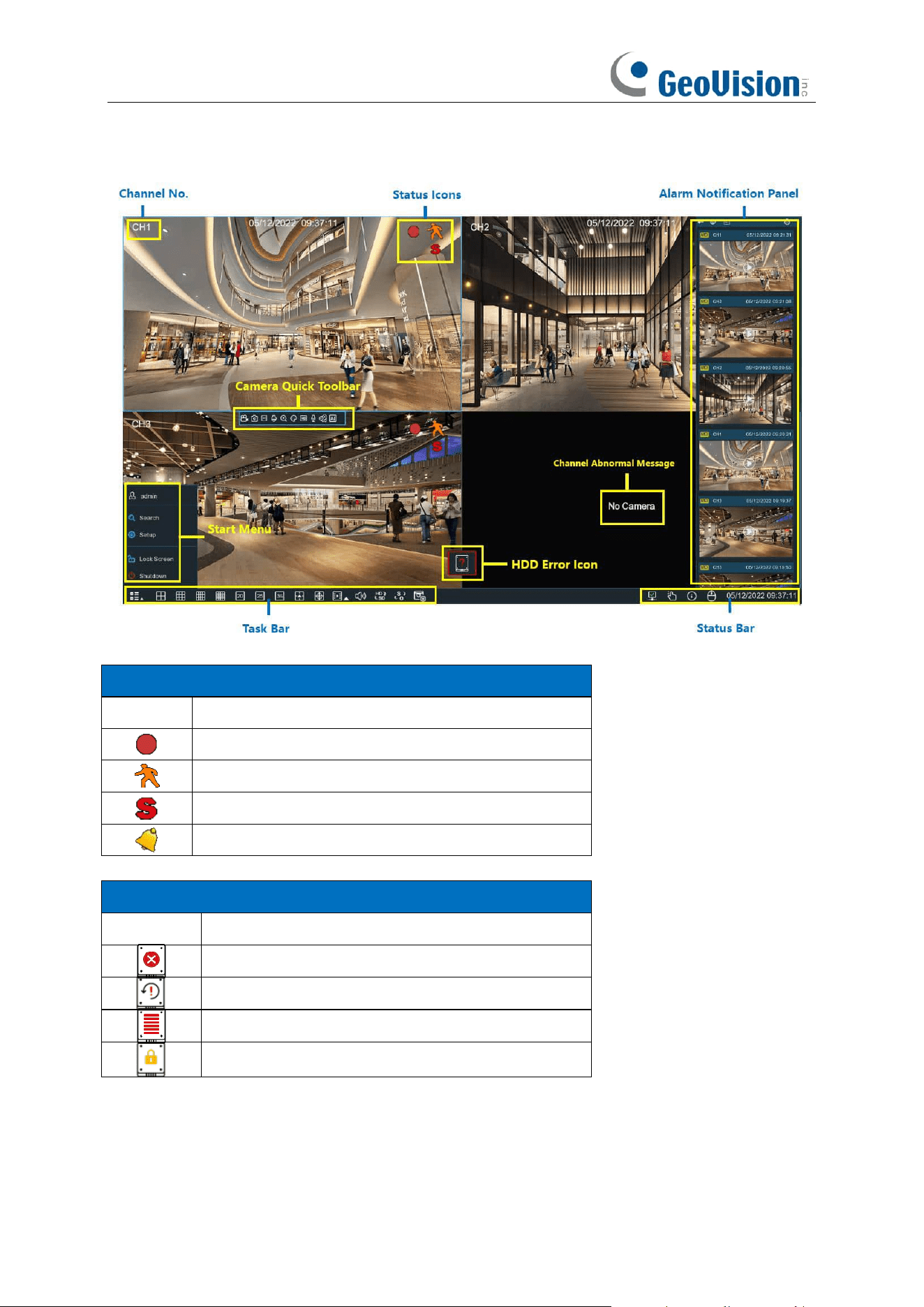
4.2 Live View Screen Overview
Status Icons
Icon
Meaning
The camera is being recorded currently
A motion alarm is happening
An intelligent or Ai alarm is happening
The external I/O alarm device is being triggered
HDD Error Icons
Icon
Meaning
HDD is uninstalled or in error
HDD is unformatted
HDD is full
HDD is read-only
33
Channel Abnormal Message
Message
Meaning
No Camera
No camera is added to this channel. You can click the add
icon to add a new camera.
Failed to connect to camera,
please check the network
connection!
The added camera is off-lined or lost connection. Please
check the camera working status or network connection.
You can click the edit icon to check the camera status.
User name or password error!
Incorrect user name or password of the camera. Click the
edit icon to modify.
Resource Not Enough
No enough system resource to decode the camera images,
please try to change the cameras to sub-stream mode;
If there are 2 or more cameras are using MJPEG decoding,
only 1 camera can be encoded at the same time.
No enough bandwidth for this
camera!
The camera cannot get online because the total bitrate of
all connected cameras exceeds the NVR's bandwidth
limitation.
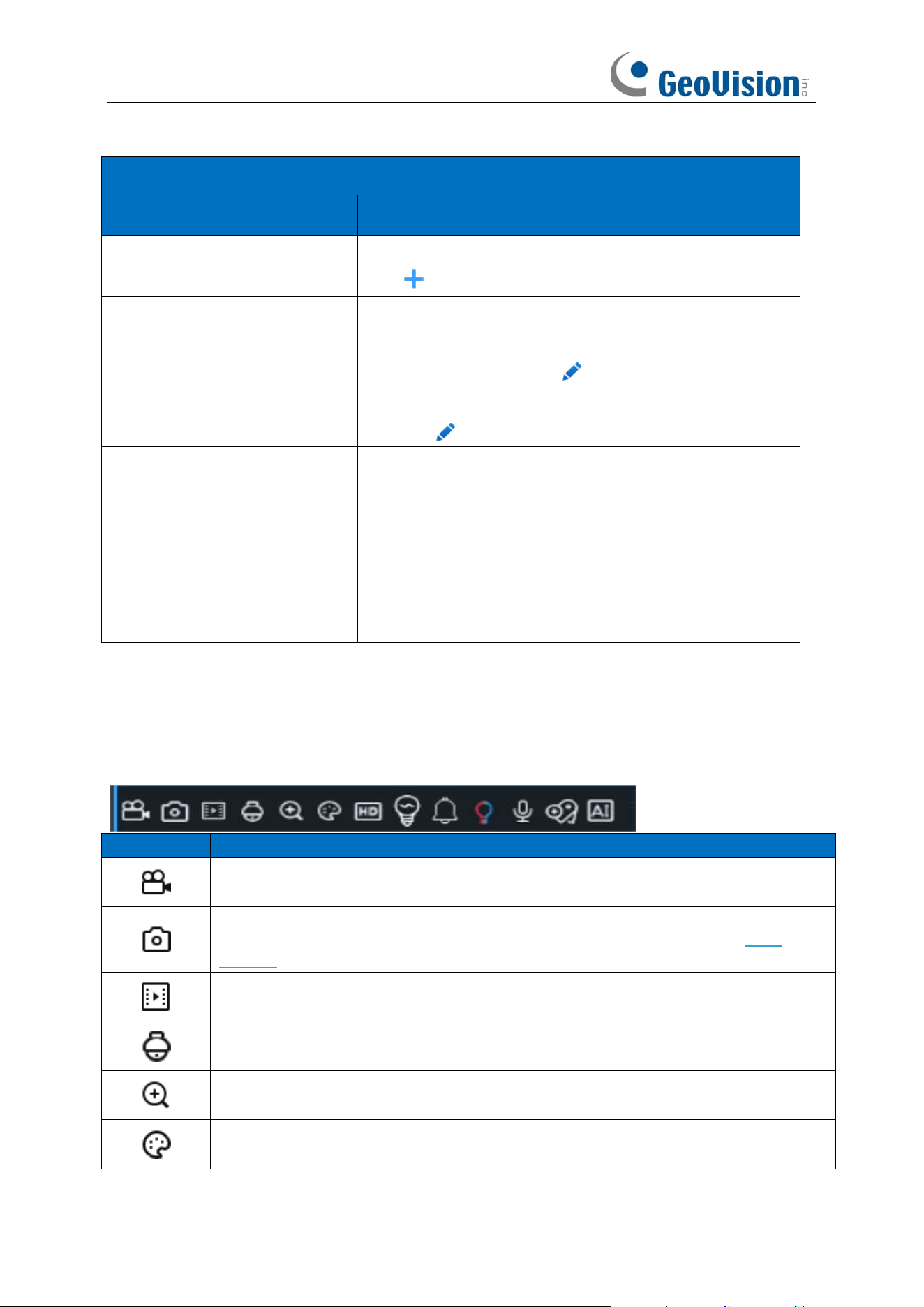
4.2.1 Camera Quick Toolbar
In live viewing, click the left button of your mouse on a connected camera to display the Camera
Quick Toolbar.
Icon
Meaning
Click to manually record the channel immediately. If the manually recording is in
process, the icon will be in red color. Click one more time to stop manual record.
Click to save a snapshot of the current camera image. Manual Capture must be
enabled to use this feature. For details on enabling Manual Capture, see 5.2.4
Capture.
Click to play the latest 5 minutes recording of this channel
Click to enter PTZ control panel;
Click to control zoom and focus of motorized varifocal lens
Click to zoom-in the channel. Scroll the wheel button of your mouse to zoom in and
zoom out the image.
Click to adjust the image color of the channel.
34
To switch the live view video stream between HD & SD. HD is mainstream images,
SD is substream images.
Click this button to enter fisheye mode. To use this button, device support is required
and a fisheye camera should be connected first.
Click to start two-way voice communication
If your camera has white light LEDs, click this button to turn on or turn off the LEDs.
If your camera has a built-in speaker, click this button to turn on or turn off the alarm
sound.
If your camera has warning light LEDs, click this button to turn on or turn off the
LEDs.
Tag button. It supports to fast search by adding a tag in live view. See more on 7.1.5
Tag Search.
AI statistics. Hover the mouse upon the icon to view AI statistics when the AI function
is activated in your NVR.
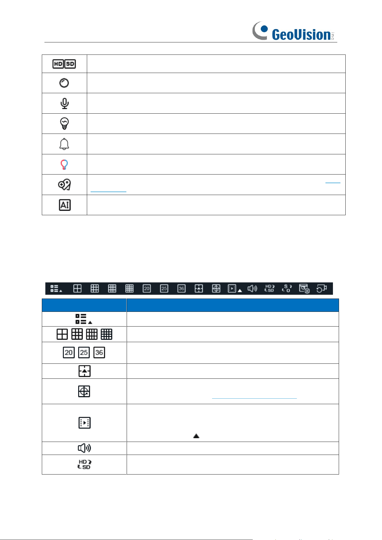
4.2.2 Taskbar
In the Taskbar, you are able to enter the system menu, start playback and change the live view
display, etc.
Icon
Meaning
Click to pop up the Start Menu
Click to display multiple channels in live view screen
Click to display 20/25/36 channels in live view screen (only applicable
to GV-RNVR256G0-N, GV-RNVR3240-N)
Click to choose more display layouts in live view screen
Click to start viewing channels in a sequence. You're able to set the
sequence display mode on 5.7.1.3 Output Configuration.
Quick playback. You can choose to play the recording for all channels
from the beginning of the day, or you can choose the play the latest 5
seconds, 10 seconds, 30 seconds, 1 minute or 5 minutes by clicking
the triangular button .
Click to adjust audio output volume
Click to switch the live view image resolution for all channels between
mainstream and substream.
35
Click to switch the image scale for all channels between original and
stretch.
Click to switch among real-time, balanced, or smooth view. It affects
the live view video quality by changing the bitrate and frame rate.
Click this button to restore the scrambled channel positions.
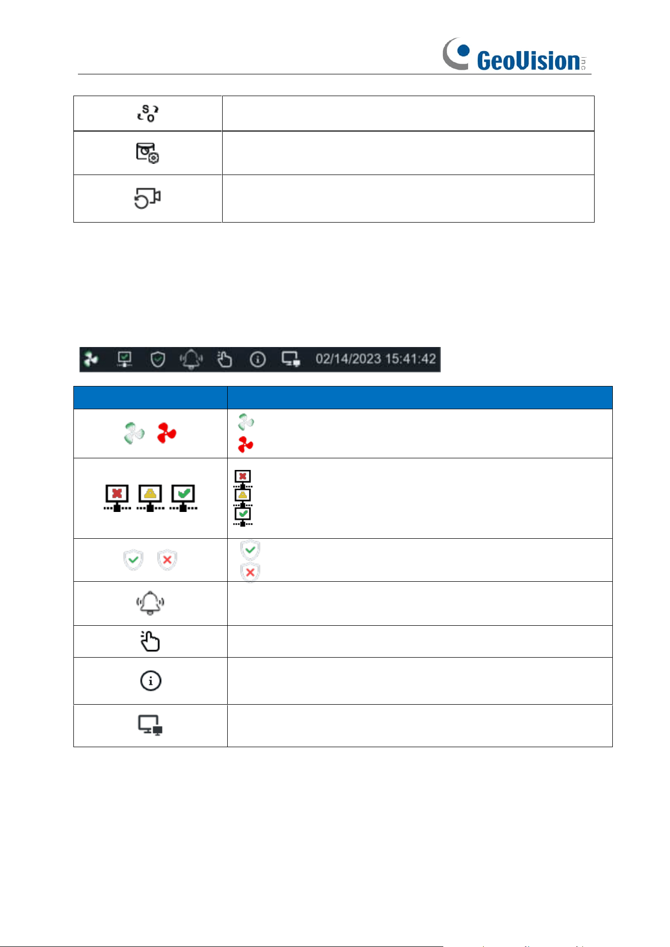
4.2.3 Status Bar
In the Status Bar, you are able to check the network connection status, turn on/off white light LEDs
and alarm sound, start and stop manual record, check the system information, disable mouse and
system time.
Icon
Meaning
Fan status is normal
Fan status is abnormal
: Network is disconnected.
: Network is connected but offline.
: Network is well connected.
The device is in arming status.
The device is in disarming status.
To turn on or turn off all the white light LEDs and alarm sound for
available cameras.
To operate manual record and manual relay alarm output
To view system information, channel information, record info and
network state.
Click this button to switch the mouse between the primary screen and
the secondary screen. To use this button, device support is required.
36
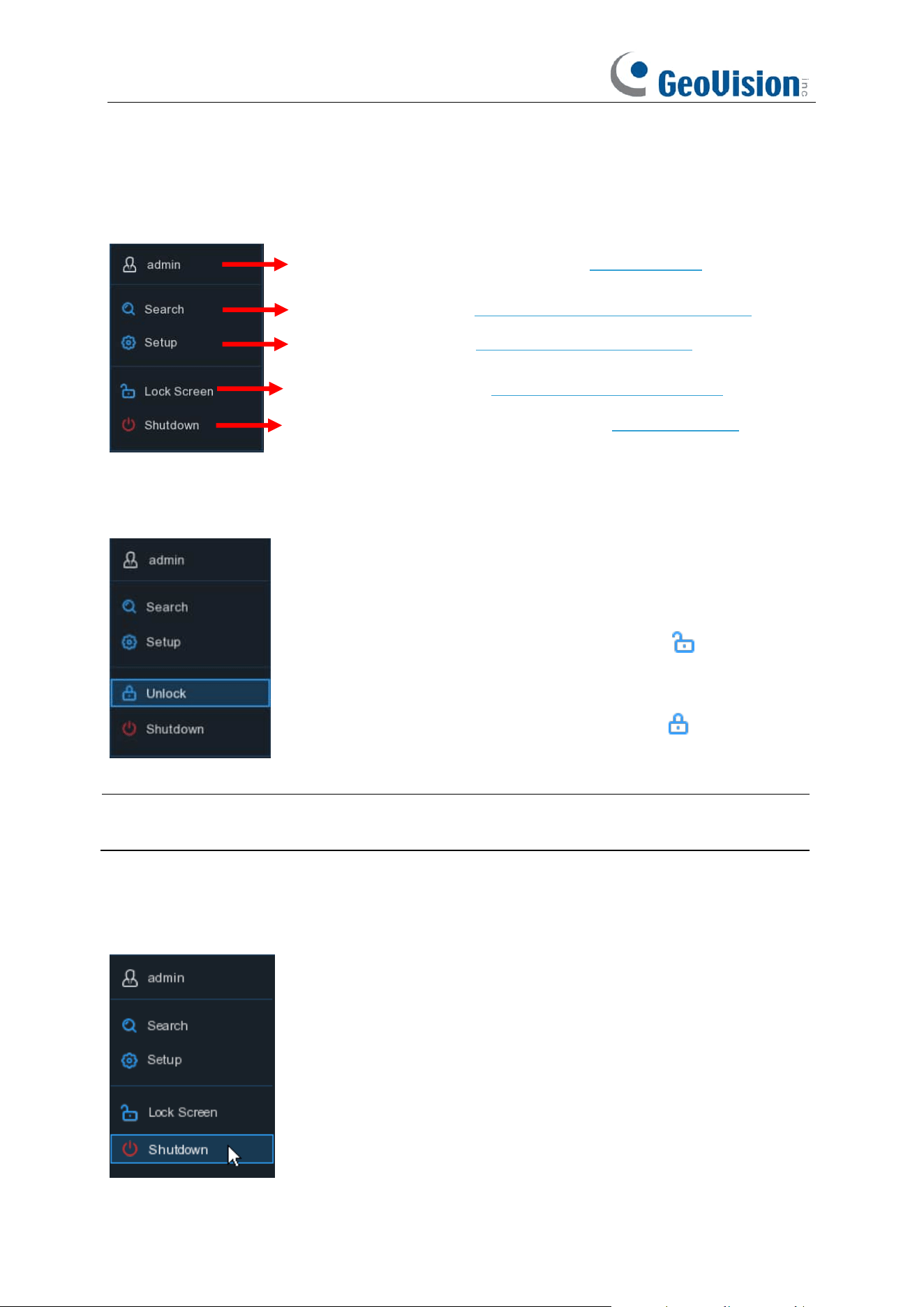
4.2.4 Start Menu
With the start menu, you can switch user, search & playback, enter system setup menu, lock &
unlock the screen, shut down, reboot & logout the system.
4.2.4.1 Unlock and Lock Screen
Note: To set up the duration of menu timeout or disable the timeout function, go to General >
System > Menu Timeouts / Idle Lock Time.
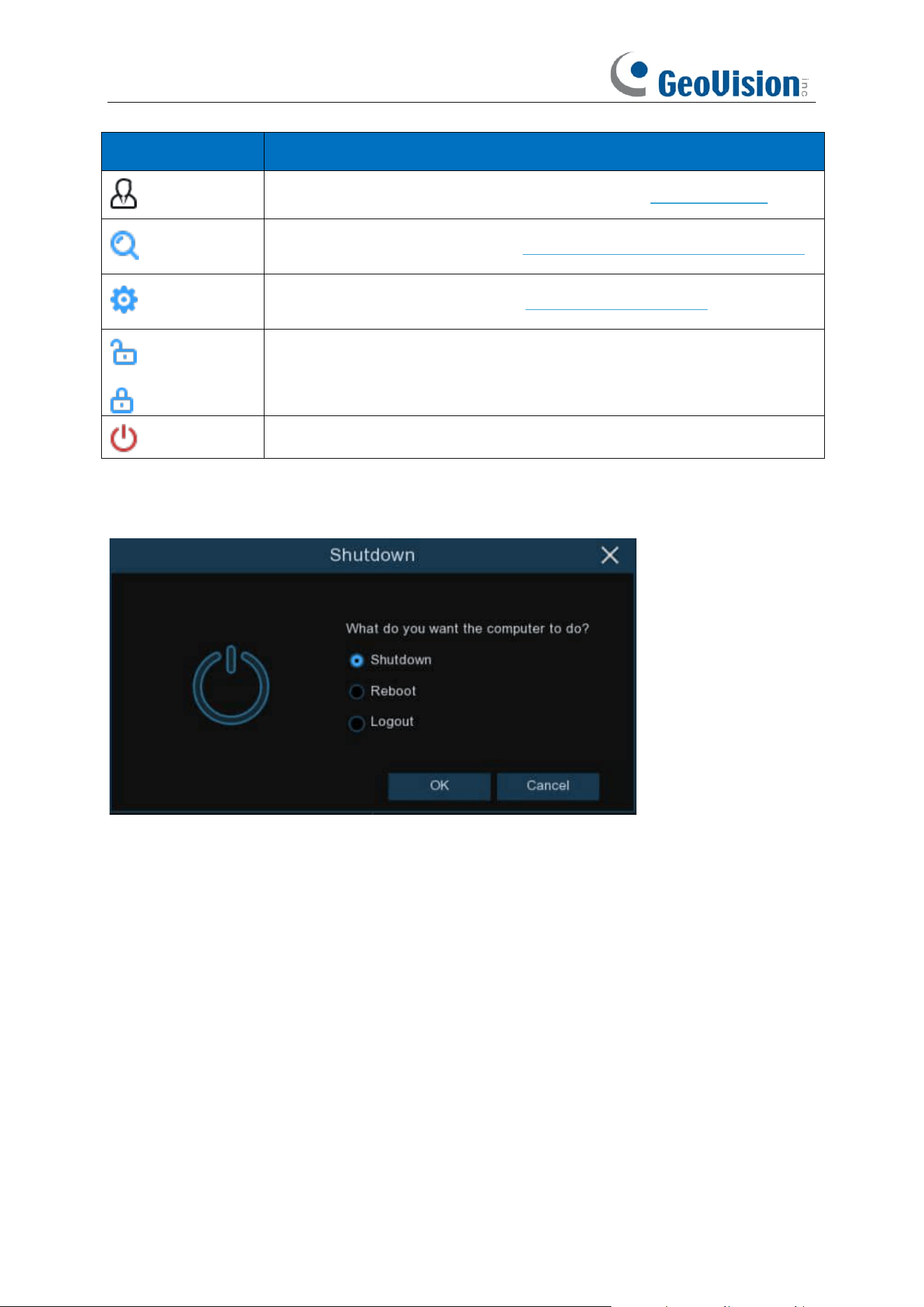
4.2.4.2 Shutdown
To switch user. To enable multi-user, see 5.7.2 Multi-user.
Search & Playback. See Chapter 7 Search, Playback & Backup
NVR System Setup. See Chapter 5 NVR System Setup
Lock & unlock screen. See 4.2.4.1 Unlock and Lock Screen.
Shutdown, reboot & logout the system. See 4.2.4.2 Shutdown.
The screen will be locked to protect unauthorized OSD operation while
the NVR is not in menu operation 1 minute.
If necessary, you can also lock the screen operation manually. To do so,
go to Star Menu, and then click the Lock Screen icon to lock the
system immediately.
If the system is locked, you can click the Unlock icon to unlock the
system for further operation.
37
Item
Description
admin
To switch user. To enable multi-user, please view on 5.7.2. Multi-user.
Search
Search & Playback. View more on Chapter 7. Search, Playback & Backup.
Setup
NVR System Setup. View more on Chapter 5. System Setup
Lock Screen
Unlock
Lock & unlock screen.
Shutdown
Shutdown, reboot & logout the system.
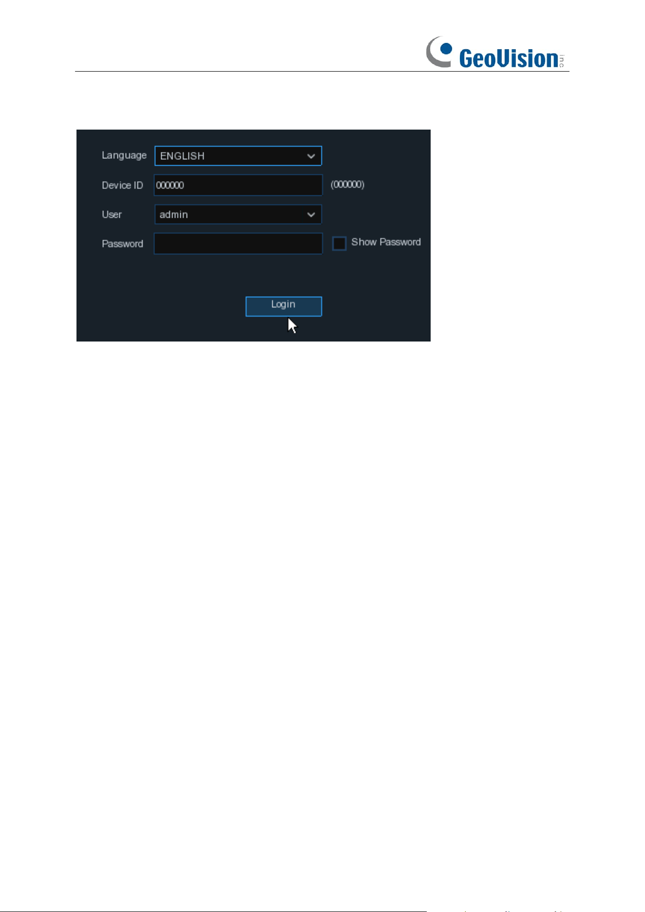
Click the
Shutdown
button from Star Menu, and the check the further action you want to move.
Click
OK
button, system will require to input the Admin password to authenticate.
38
If you choose
Logout
the system, the live viewing screen will be disappeared. You will need to
login the system for further operations.
39
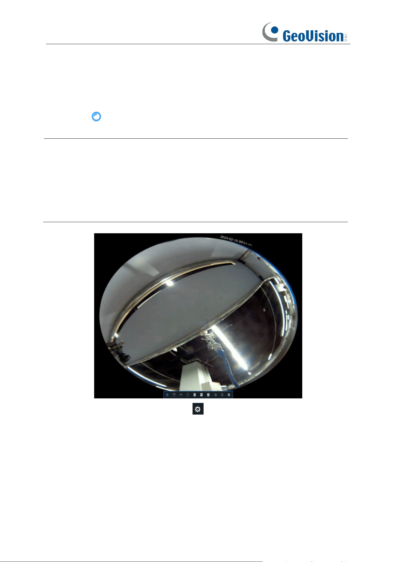
4.2.5 Fisheye Camera
After a fisheye camera is added to the device and the device goes online, the fisheye operation
icon is displayed in the shortcut menu of the preview channel area and the playback menu. You
can click the button to open the fisheye-mode operation page.
Note:
1. Only GV-RNVR256G0-N supports fisheye dewarping. GV-RNVRL810-P / RNVR3240-N
does not support fisheye dewarping.
2. A maximum of 1 channel is supported for fisheye dewarping.
3. Only Internet Explore supports the fisheye dewarping function on the Web interface.
4. Fisheye dewarping is not supported by playback recordings.
5. To enable the fisheye mode for other cameras, go to Channel > Channel, click the Edit
icon on the desired camera, and select Fisheye for the Camera Mode.
On the fisheye-mode operation page, click the button on the toolbar at the bottom to open the
menu for setting the fisheye camera installation mode. Then, select the mode in accordance with
the actual installation mode, and save the setting to make it take effect.
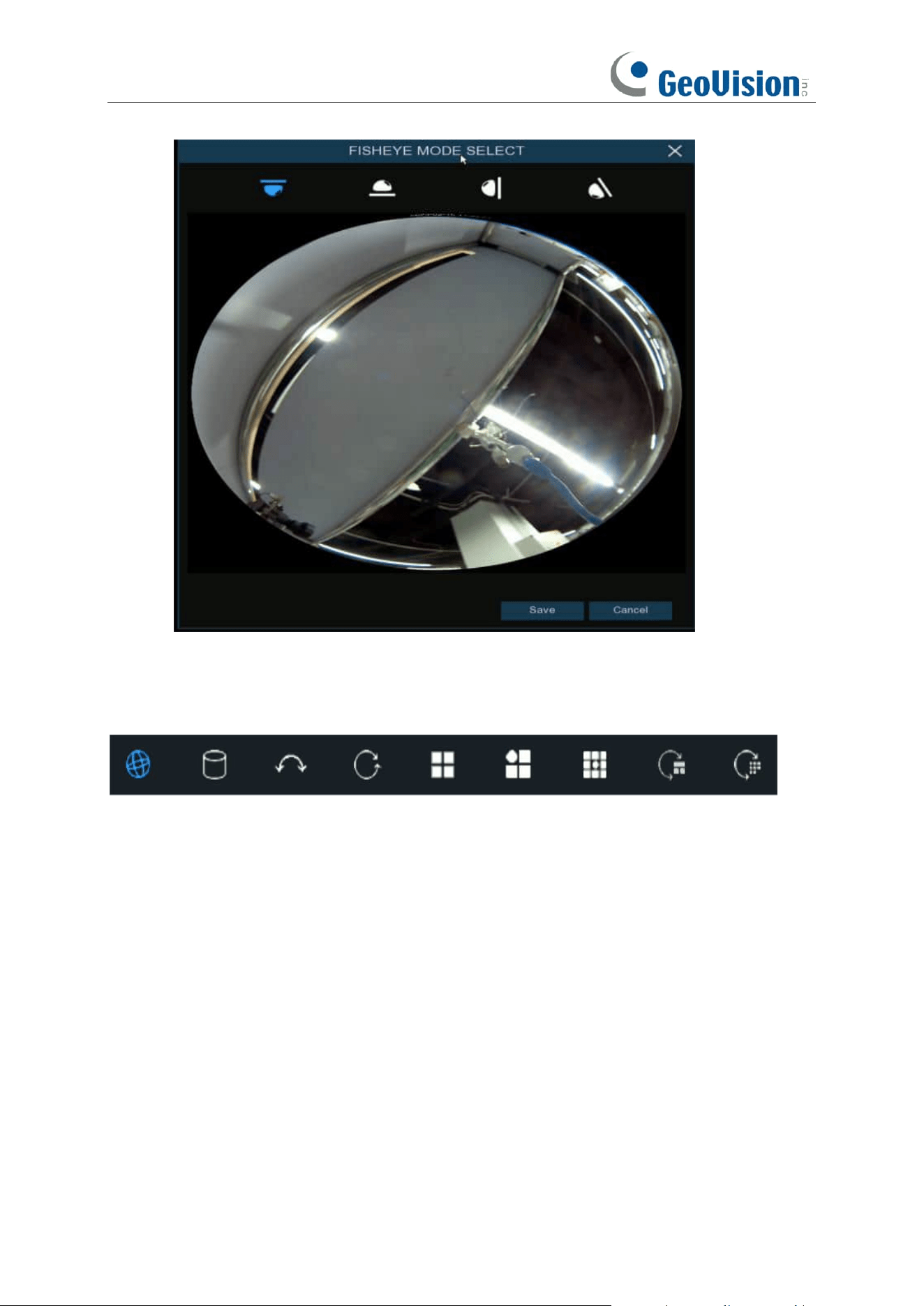
40
After the corresponding fisheye installation mode is set, the viewing modes supported in the
selected installation mode are displayed on the toolbar at the bottom. You can switch the modes
as needed and you can also drag and zoom the screen.
41
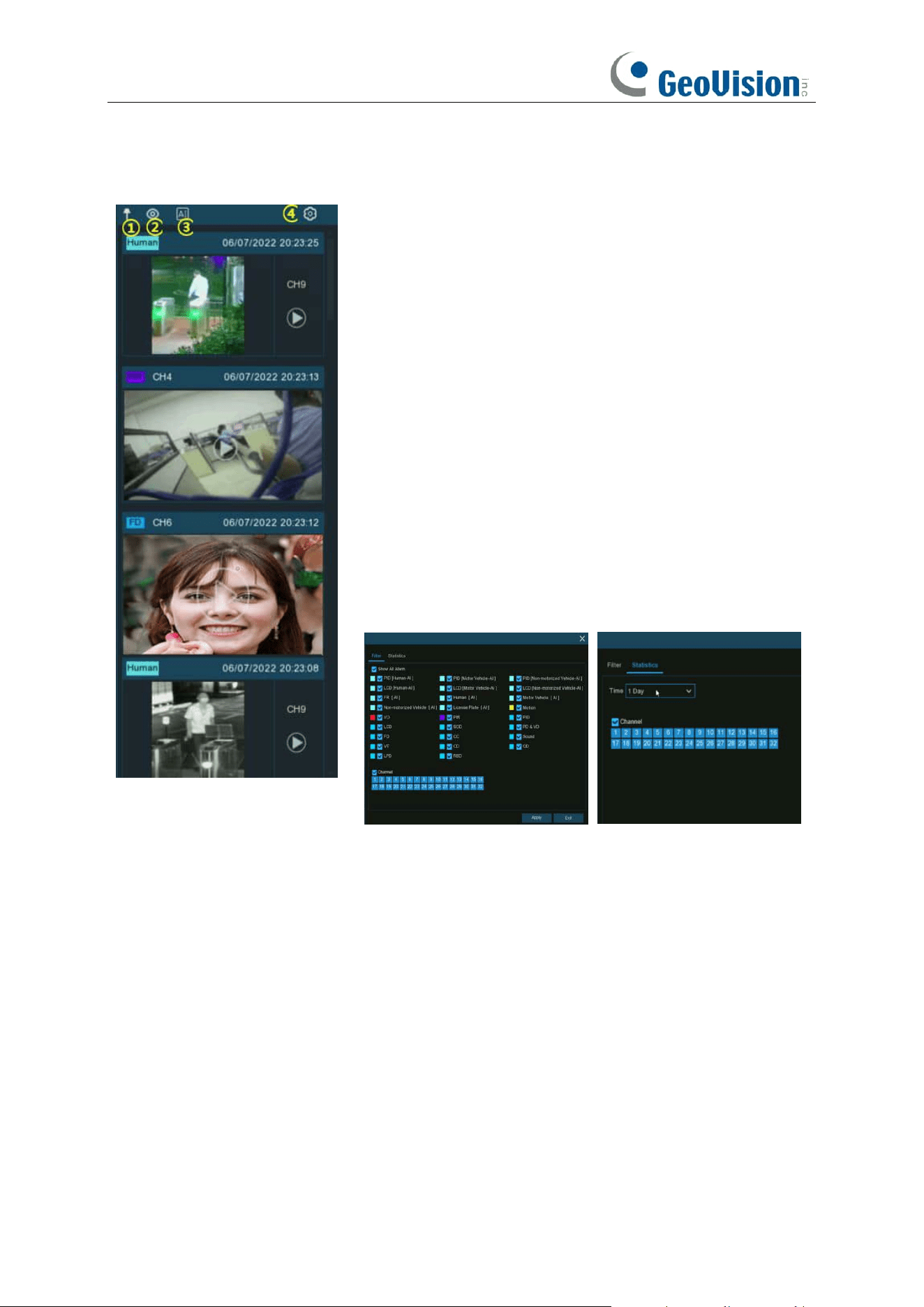
4.2.6 Alarm Notification Panel
The Alarm Notification Panel displays thumbnails of alarm
events that have occurred. Events are color-coded according
to the event type. Use the mouse scroll wheel to scroll up and
down (place the mouse cursor over the notification panel first).
Click the play button next to or over the thumbnail to play the
event.
1. Click to display the notification panel at all times.
2. Click to hide the notification panel.
3. Click to reveal AI statistics information.
4. Click to reveal the Filter and Statistics functions (shown
below).
Use the Filter function to customize which alerts and which
camera will appear in the notification panel. You can also
customize the time duration and channels you want to display
in AI statistics.
42
Chapter 5 NVR System Setup
You can configure the NVR for Channel, Record, Alarm, Network, Device & System from
Start
Menu
→
Setup
.
5.1 Channel
In this section, you can configure the camera, live view display, manage IP cameras, adjust IP
camera’s image, PTZ setup, motion setup, convert mode, and more.
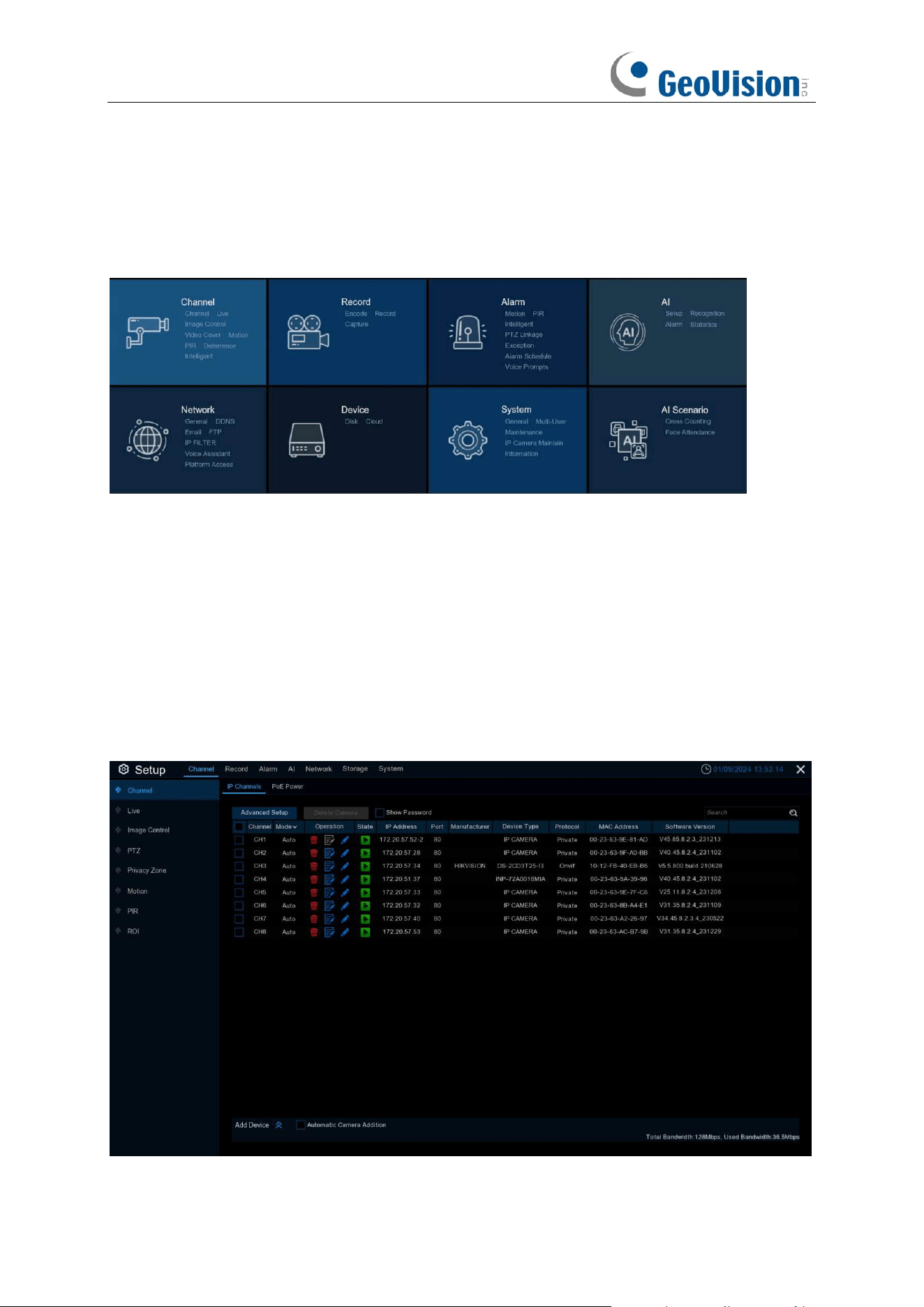
5.1.1 IP Channels
You're able to add and delete IP cameras in this menu.

43
1. Click Add Device to expand and collapse the device search window.
a. Click Search button to search and display the devices under the same LAN. Based on
the search result, select one or more devices, and click Add to enter the corresponding
information to complete the addition.
b. Based on the search result, you can select multiple devices, click Batch IP Modification,
set the correct information, you can batch IP modification for the selected cameras.
c. Check Automatic Camera Addition, the device will automatically add cameras to the
channels where cameras are not added.
2. Click the Advanced Setup button to enter the device's password to open the Advanced
Setup page, where you can do the following:
a. Default Password: Set the default password for the device to connect to the camera via
Private/Onvif/RTSP protocol. The default password for the Private protocol can be used
to activate the connected camera that is not activated. When Use the Admin password
as camera activation/connection password is checked, the Private protocol will use the
device administrator password for activation/connection of the accessed camera.
b. Modify Camera Password: You can modify the password of the online camera.
c. Priority of PoE Channels (only supported by PoE NVR):
i. Enable the priority of PoE Channels. If the channel has been manually added
cameras. Continue to access the camera on the corresponding PoE port of the
channel. The manually added camera will be replaced with the PoE accessed
camera. (Unchecked Remember My Selection, it will only take effect once)
ii. Enable Manual Add Priority. If a camera has been manually added to a channel,
continue to access the camera on the corresponding PoE port of the channel, and
the previously manually added camera will not be replaced by a PoE-accessed
camera. (Unchecked Remember My Selection, which takes effect only once)
iii. If you do not enable any priority item. Cameras have been manually added to the
current channel. Continue to access the camera on the corresponding PoE port of
the channel. a pop-up window will prompt that the camera already exists on the
current channel and ask whether to replace it.
d. Restore IP Channel Connection: When the device forgets the password and resets the
password by restoring the factory settings. You can click Restore IP Channel Connection
to restore the channel connection parameters before restoring the factory settings, and
add the original online camera with one click.
e. Export & Import Camera: You can export the added IPC information as a backup. It can
be used for re-importing or importing into other devices after the device is restored to
factory settings (the exported information does not contain the connection password).
3. Select the camera that has been added to the device, click the Delete Camera button to
delete the camera.
4. Check Show Password, enter the device password to verify that the camera has been added
to the device connection password can be displayed.
Click the Search icon to search for online cameras on your LAN, select the camera you want to
add and enter the correct information to add it.
44
5.1.1.1 Connect External Cameras from LAN or Internet
If you want to connect to an IP camera from LAN or internet, please make sure your NVR is
well-connected to the LAN and or internet.
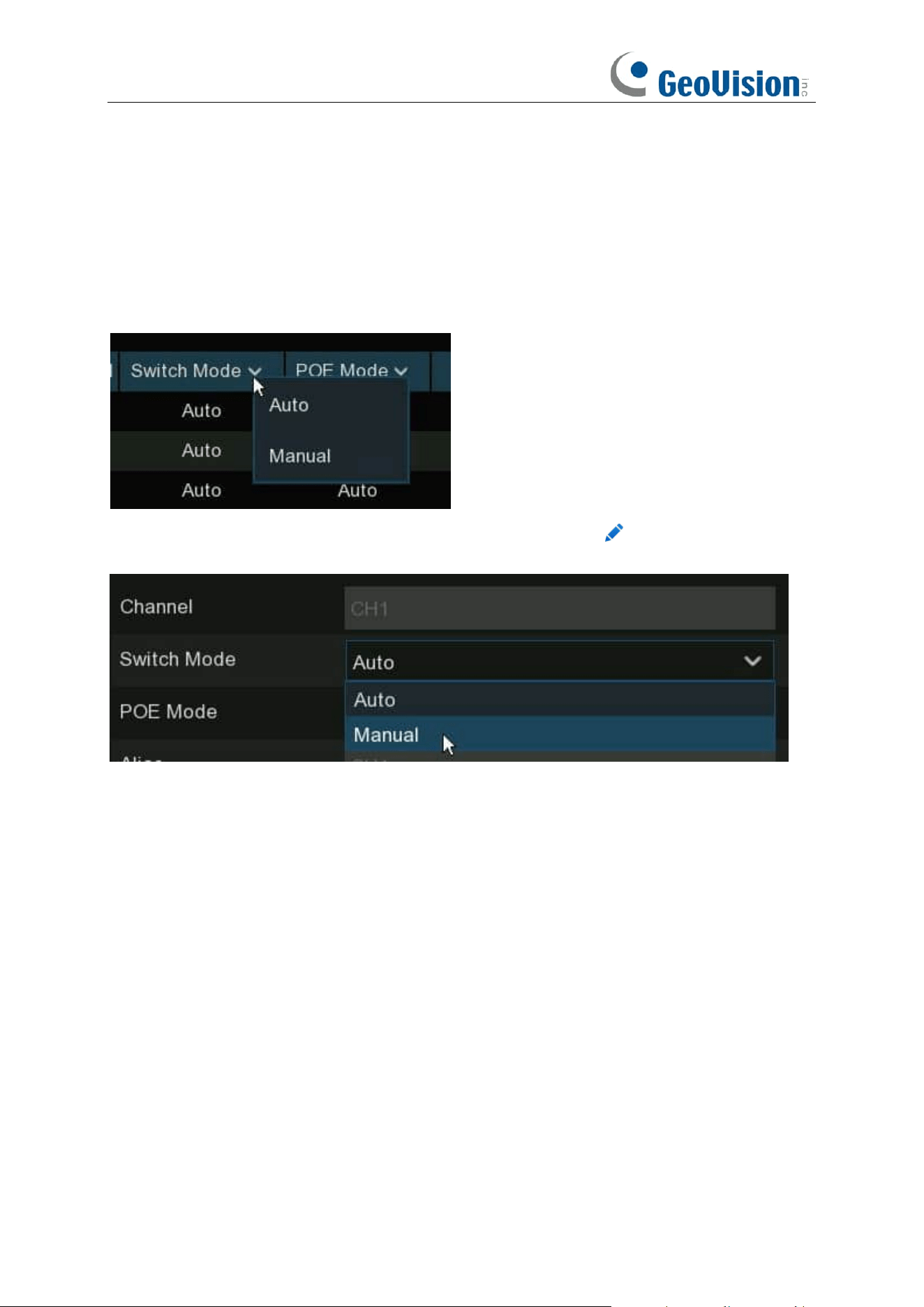
If you want to all channels manually, click the drop-down arrow next to Switch Mode, and then
select "Manual".
If you want to add an individual channel manually, click the edit icon in the channel list, and
then click the drop-down arrow next to Switch Mode to select "Manual" and click OK to save.
45
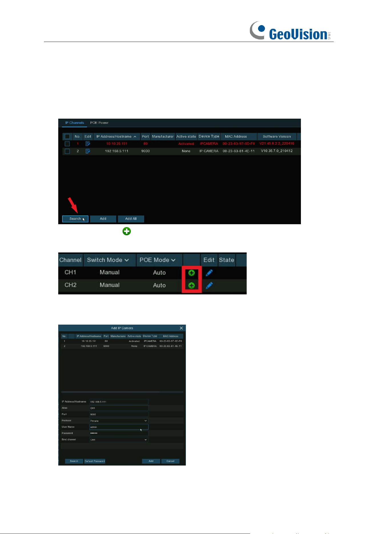
5.1.1.1.1 Add Individual Camera in the LAN
1. Change the PoE mode to be Manual.
2. Click
Search
button, all available cameras in the LAN will be displayed.
3. Or click the Add icon in the channel list to add a camera to an individual channel. Click
Search
button, all available cameras in the LAN will be displayed.
4. Click on the camera you want to connect, and then complete below parameters, and input the
user name and password of the camera and then click Add button.
46
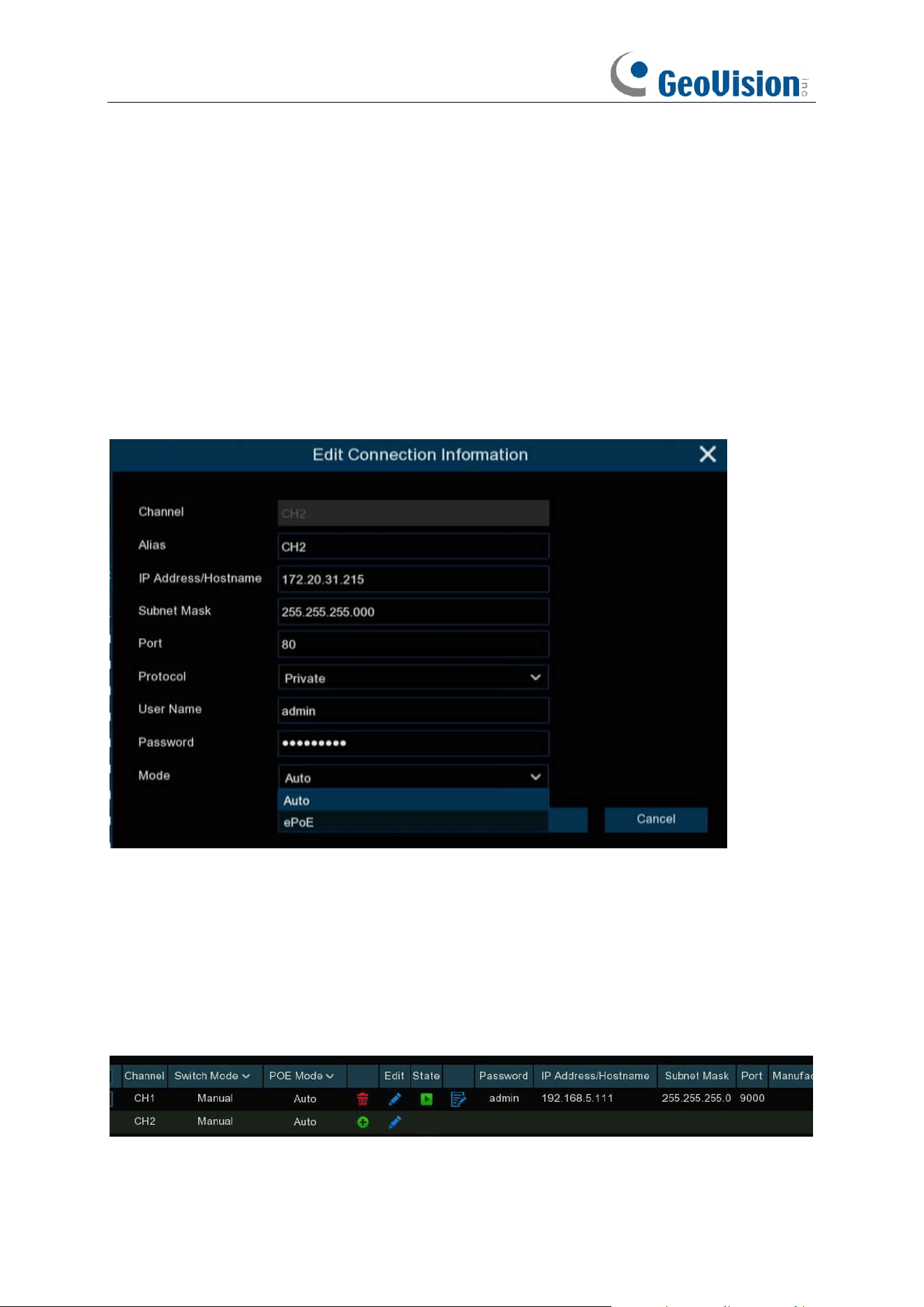
Alias: To define the camera ID title you want to display in the live view screen.
Port: Camera communication port. It is set to 80 by default. Modify it if necessary.
Protocol: To select the connection protocol.
⚫ Select
Onvif
for GV-IP cameras
⚫ Select
Private
for GV-RBL5800 / RBL5811 / REB5800 / RFER12700
⚫ Select
RTSP
, and type the commands as shown below:
Main Stream: rtsp://IP address:port/rtsp/streaming?channel=xx&subtype=0
Sub Stream: rtsp://IP address:port/rtsp/streaming?channel=xx&subtype=1
Bind channel: To determine which channel you want to add the camera.
Mode: Click the Mode drop-down box to select auto or ePoE mode. Note the ePoE mode is only
supported by models with PoE ports.
Note: In auto, the transmission bandwidth of 100Mbps supports a maximum transmission distance
of about 120 meters; in ePOE mode will limit the transmission bandwidth to 10Mbps to expand the
transmission distance to about 230 meters. (To ensure transmission stability, Cat5E or Cat6 cable
is recommended)
Click Add button.
5. The added camera will be displayed in the channel list.
47
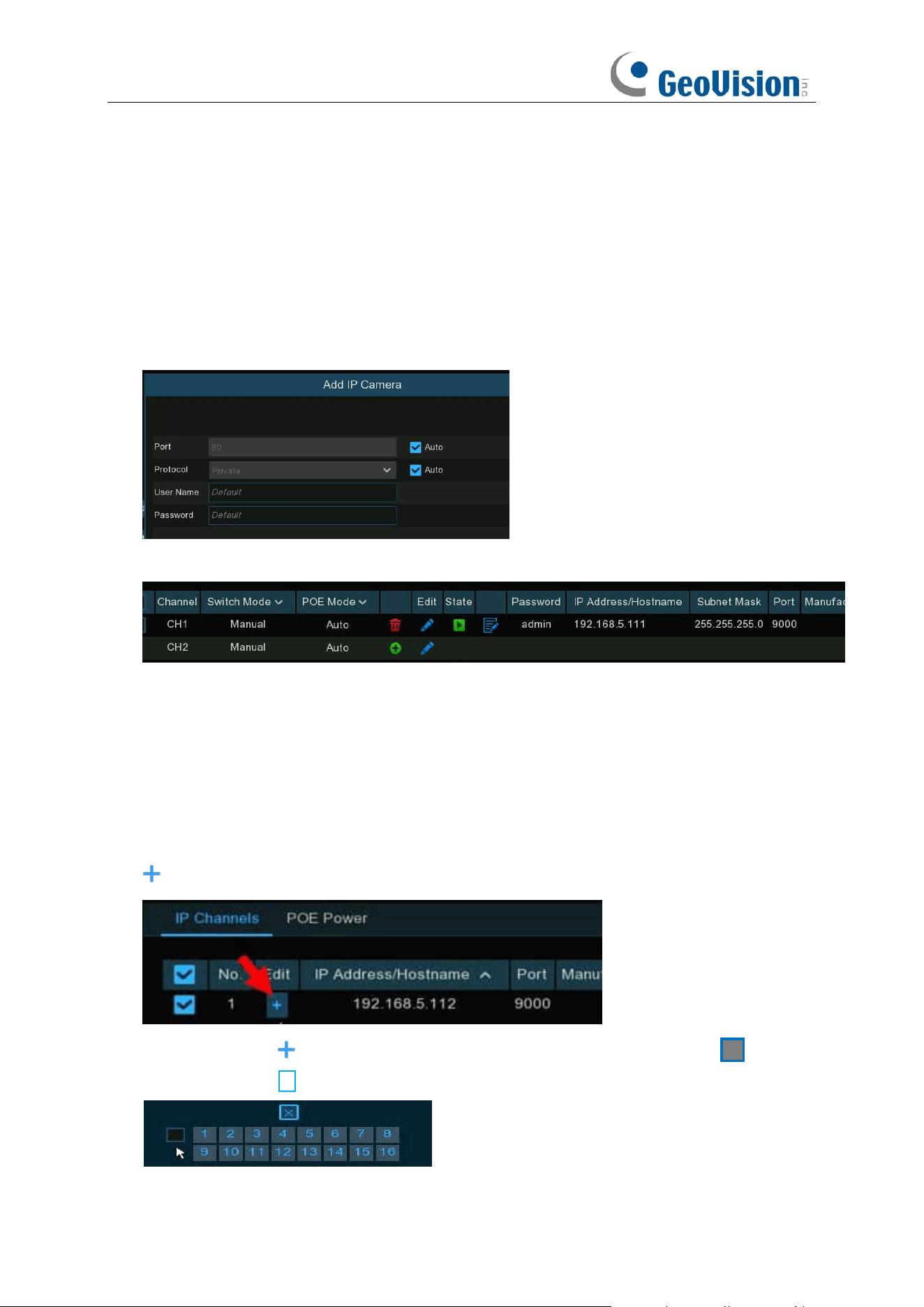
5.1.1.1.2 Add Multiplex Cameras in the LAN
1. Click
Search
button, all available cameras in the LAN will be displayed. Or click
Add All
button, the NVR will search & add all available cameras in the LAN.
2. Select the cameras from the search result, and then click “
Add
”. You would need to input the
user name and password of the cameras. Please make sure all the cameras you want to add
use the same user name and password. Otherwise, the cameras with different user name and
password will be unable to get connected.
3. The added cameras will be displayed in the channel list.
5.1.1.1.3 Add Cameras from Other NVR in the LAN
The NVR allows to add cameras from other NVRs in the local network.
1. Click
Search
button, all available devices in the LAN will be displayed. There is an edit icon
displayed if the device is an NVR.
2. Click the edit icon and select the camera channel one by one or tick the box to select
all cameras. Click icon to go back to search list.
48
3. Select the NVR in the search list, and then click
Add
button.
4. Input the user name and password of the NVR and then click
Add
button.
5. The added cameras will be displayed in the channel list.
49
5.1.1.1.4 Add Cameras from the Internet
If your NVR is connected to internet, you're able to add cameras from internet with WAN IP
address.
1. Click
Add
button in the search page.
2. Input the IP address or domain name, port, protocol, user name & password of the IP camera.
Click
Add
button to add the camera.
50
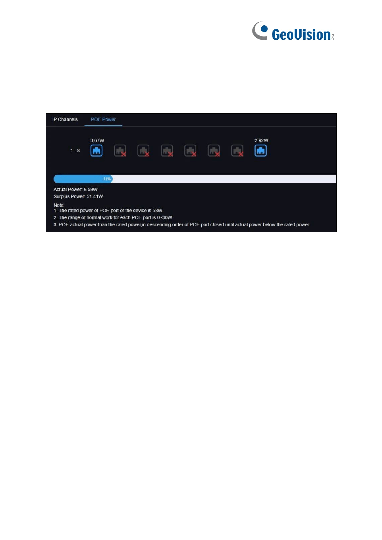
5.1.1.2 PoE Power
In this page, you will find the real-time power consumption of each PoE port, total actual power &
rated power.
Actual power usage: Used power
Surplus power usage: remaining power
Note:
1. The total rated power of the device's POE interface is 58W maximum. The total rated power
of the POE interface of different models of NVR is not the same).
2. The normal operating range of each POE port is 0 ~ 30W.
3. If the actual power of POE port is higher than the rated power, it will be reduced in the order
of POE port closing until the actual power of POE port is lower than the rated power.
51
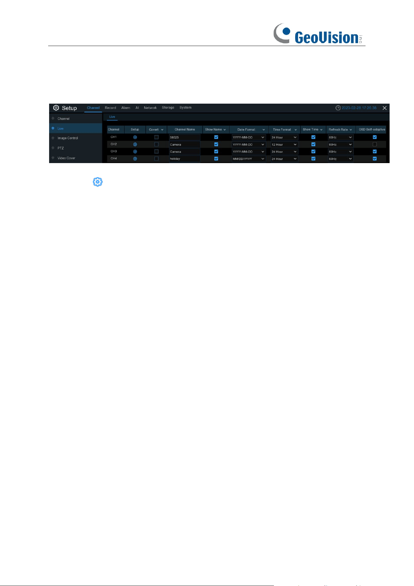
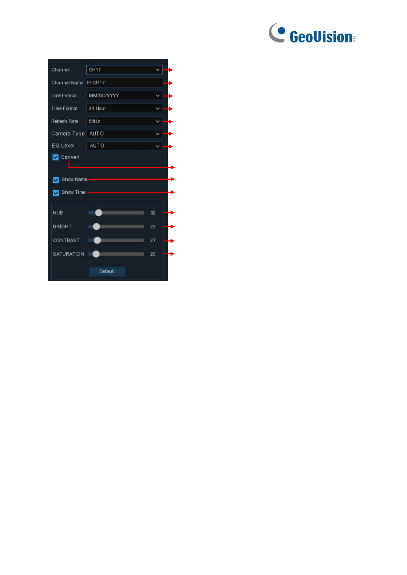
5.1.2 Live
To configure camera parameters.
Channel
: Display channel number.
Setup
: Click icon into the setup page.
Hide Preview: To hide the camera images in live view.
Convert: To hide the camera images in live view. If the covert is enabled, only live view images will
be hidden. Recording images won't be affected. Enable this if your NVR and TV is in a public area
(shop, warehouse, etc.), but you don't want others to see an image from the camera.
Channel Name: Give a name to the camera.
Show Name: Leave this enabled to display the camera name in Live View mode, otherwise click
the checkbox to disable it. It affects both live view & recording images.
Date Format: To choose a date format.
Time Format: To choose a time format.
Show Time: Leave this enabled, as a timestamp will be embedded on all video recordings. Click
the checkbox if you wish to disable it. It affects both live view & recording images.
Refresh Rate: Choose the right value according to the frequency of alternating current in your
region.
OSD Self-adaptive / Auto Text Color: Used to set whether to change the font color of OSD in
accordance with the screen background to ensure clear display.
52
Choose a channel to configure
Give a name to the camera
Date format to display for the camera (for IP camera only)
Time format to display for the camera (for IP camera only)
Adjust the Bright value for the image color
Adjust the Contrast value for the image color
Adjust the Saturation value for the image color
Refresh Rate of the camera (for IP camera only)
To show the camera name in live view screen
To show the system time in live view screen
Choose a camera type (Auto, AHD, TVI, CVI) for analog camera
Choose an AHD EQ (Enhanced Quality) level depends on your
camera video cable
Check the box If you want to hide the live image of this channel
Adjust the Hue value for the image color
Click Default to load default settings, click Apply to save settings,
click right buttons of your mouse to exit.
53
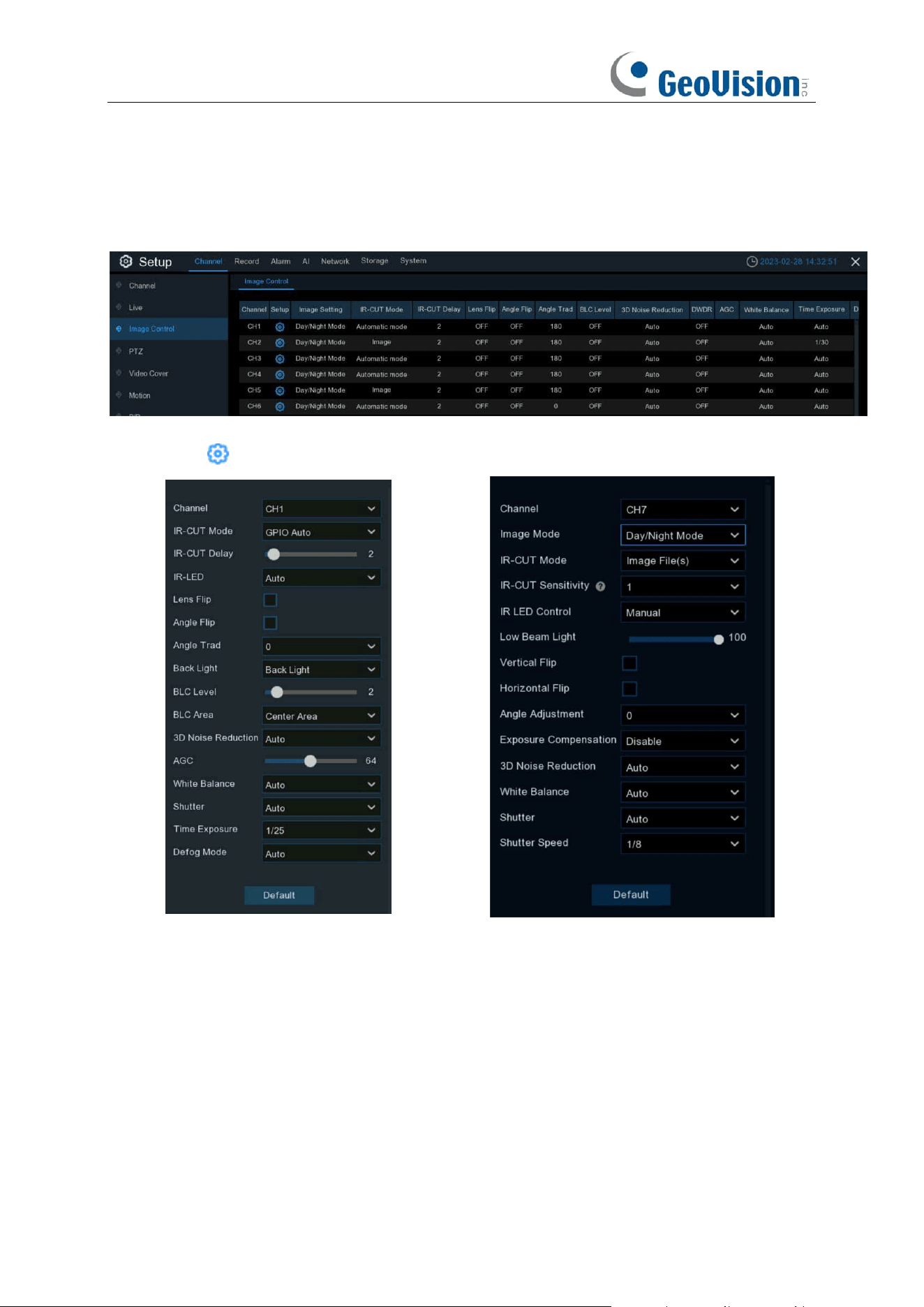
5.1.3 Image Control
This menu allows you to control image settings for supported IP cameras. If the camera is
connected to the NVR with Onvif protocol, it might be not supported to configure.
Setup
: Click icon into the setup page. The interface varies based on different models.
Channel: Choose a channel to configure.
IR-CUT Mode: Lets you choose how the camera handles color and how it manages the transition
from daytime to night-time and vice versa:
➔
GPIO AUTO
will instruct the camera to switch automatically from "Color Mode" to "Black
White mode" and vice versa. It is accomplished through the light sensor.
➔
Color Mode
will instruct the camera to operate in color mode only. In low light conditions, the
color will be quite faint. Image clarity will also be reduced in low-light conditions.
➔
Black White Mode
will instruct the camera to operate in black & white mode only.

54
➔
Image Mode
will instruct the camera to switch automatically from "Color Mode" to "Black
White mode" and vice versa. It is accomplished through the software.
➔
B/W Schedule
allows to set the images as black & white color in a certain duration.
IR-CUT Delay: Controls the delay of the IR cut filter when transitioning from daytime to night-time.
The default setting will be suitable for most camera locations but can be adjusted if needed. Click
and hold the slider left or right to change. The higher the number, the greater the delay.
IR-LED: To configure the IR LRD lighting method.
➔
Smart IR:
If you want the LED lighting to be managed by the system, then select this.
➔
Manual
: You're able to configure the brightness of the LED lights including low-beam lights
and high-beam lights individually.
➔
OFF:
Turn off the LED light always
Vertical Flip: Invert the image up and down.
Horizontal Flip: Invert image orientation horizontally.
Corridor Mode: This allows you to make better use of the camera's vertical angle for an optimized
view of long, narrow scenes. Enable this if your camera is viewing a narrow corridor.
Angle Trad / Adjustment: Rotate the image 180°.
Mirror: Turn the image upside down and/or horizontally reverse the orientation of the image.
Exposure Compensation: When the surrounding illumination and the object have large
differences in brightness, you can enable the exposure compensation to get a better image.
➔
DWDR:
Images produced by wide dynamic range (WDR) function sensors can have proper
exposure on both the darker and lighter parts of the image, giving more detail across a wider
dynamic range between the shadows and highlights by brightening dark areas and darkening
bright areas. If it is enabled, click and hold the slider left or right to change the
WDR
Level
.
➔
HLC:
High Light Compensation (HLC) allows your camera to compensate for brighter parts of
your image, maintaining detail in brighter parts of the image that would otherwise be blown out.
When you enable HLC, the camera will take bright spotlight-like areas into consideration and
adjust the exposure accordingly. With HLC, your camera will try to properly expose your entire
scene while reducing the brightness of the highlights. If it is enabled, click and hold the slider
left or right to change the
HLC
Level
.
➔
BLC:
Back Light Compensation (BLC) allows you to choose which areas of your scene should
be properly exposed instead of letting the camera choose for you. By enabling BLC, the
camera over-exposes the brighter parts of your image in order to properly expose the darker
parts. If it is enabled, click and hold the slider left or right to change the
BLC
Level
.
➔
Disable
:
Disable exposure compensation.
White Balance: Used to set white balance. There are two mode options.
➔
Auto
: In this mode, the white light is adjusted by the default parameters.
➔
Manual
: In this mode, you can manually set the synthetic gained white light of red, green, and
blue.

55
Shutter: Used to set the shutter exposure time. There are two mode options.
➔
Auto
: In this mode, a proper exposure time is automatically selected in accordance with the
configured
Time Exposure
value.
➔
Manual
: In this mode, the configured
Time Exposure
value is used.
Time Exposure: Used to set the exposure time of the camera. This parameter is used together
with the Shutter parameter.
3D Noise Reduction: Used to reduce the noise in the image so as to make the image clearer.
There are three mode options.
➔
Auto
: In this mode, the camera automatically selects the noise reduction effect in accordance
with algorithms.
➔
OFF
: The noise reduction function is disabled.
➔
Manual
: In this mode, image noise is reduced in accordance with the noise reduction
coefficient manually configured.
Default: Click this button to restore the default image parameter setting.
56
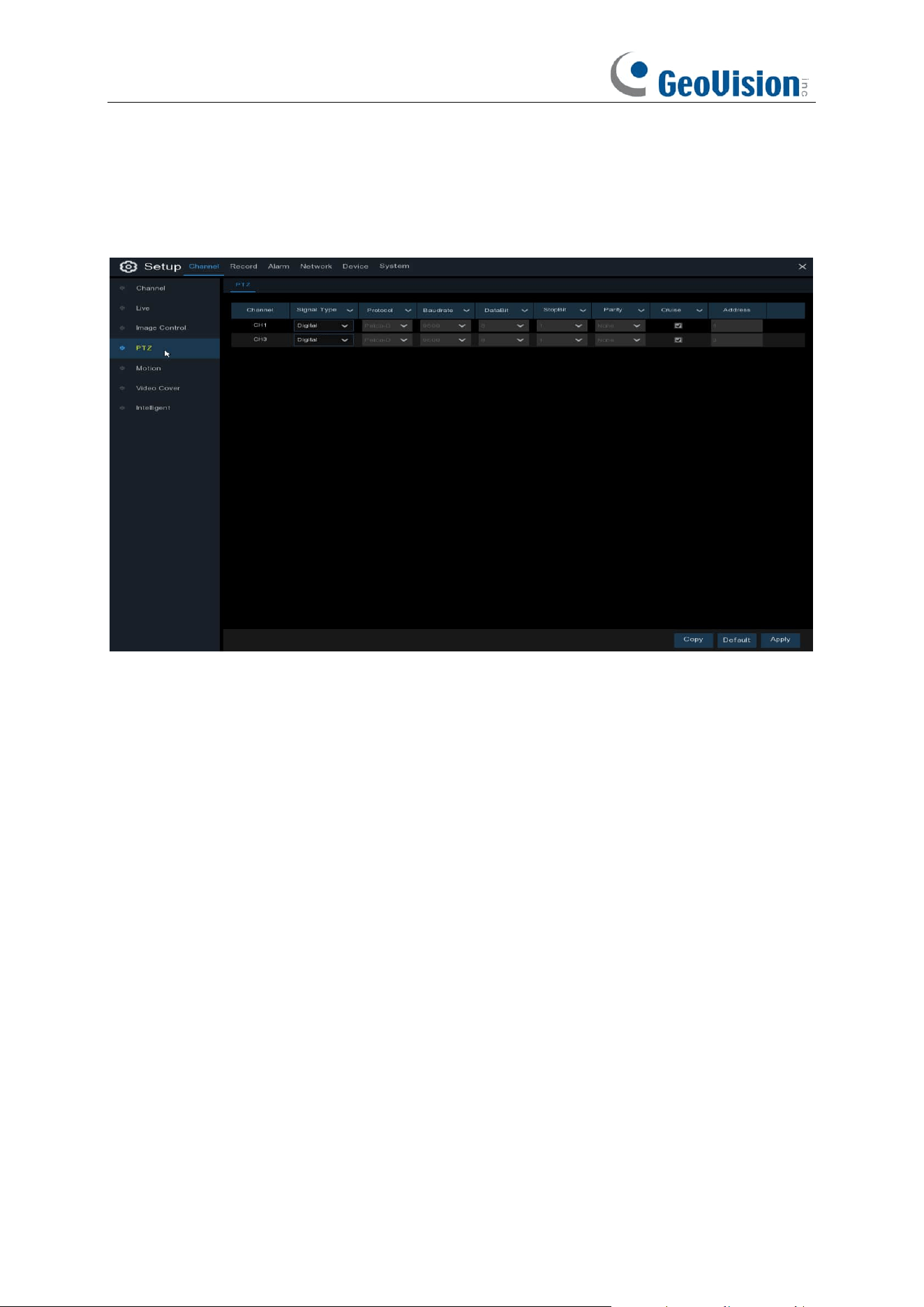
5.1.4 PTZ
This menu allows you to configure the PTZ (Pan-Tilt-Zoom) settings for the dome camera.
Channel:
Channel name
Signal Type:
Analog for analog channels, Analog & Digital for IP channels.
Protocol:
Choose the communication protocol between the PTZ capable camera and NVR. If
your camera support UTC (Up the Coax) function, you can choose COAX1 or COAX2 to display
your camera OSD menu or control the UTC PTZ function.
Baudrate:
The speed of the information sent from the NVR to the PTZ-capable camera. Make
sure it matches the compatibility level of your PTZ-capable camera.
DataBit / StopBit:
The information between the NVR and PTZ-capable camera is sent in
individual packages. The
DataBit
indicates the number of bits sent, while the
EndBit
indicates the
end of the package and the beginning of the next (information) package. The available parameters
for
DataBit
are:
8
,
7
,
6
,
5
. the available parameters for the
StopBit
are
1
or
2
.
Parity
: For error check. See the documentation of your PTZ-capable camera, to configure this
setting.
Cruise
: Enable to use the Cruise mode. In order to use the Cruise mode, you need to set a
number of preset points.
Address
: Set the command address of the PTZ system. Be noted that each PTZ-capable camera
needs a unique address to function properly
57
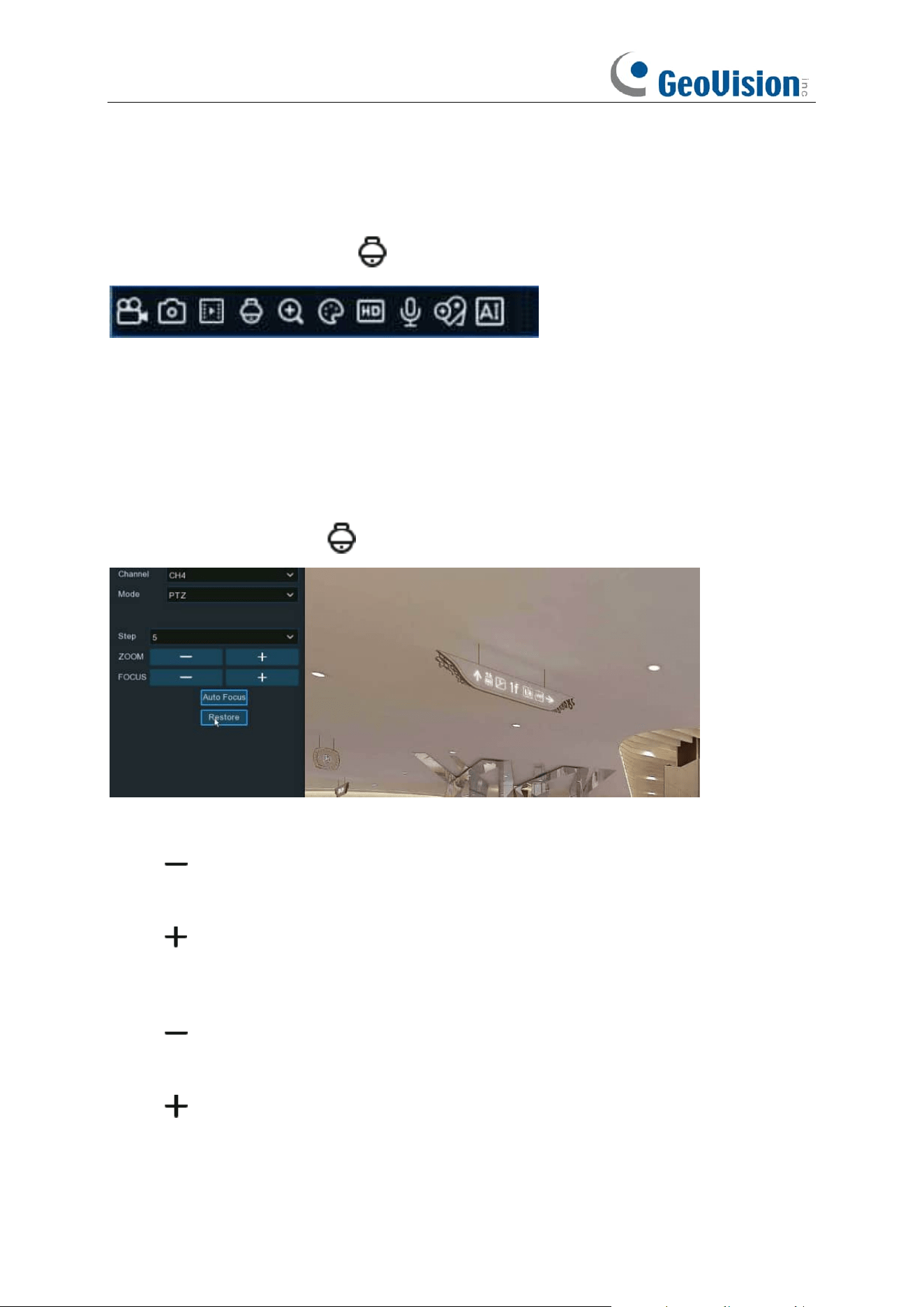
5.1.4.1 MFZ & PTZ control
In live viewing, click the left button of your mouse on a connected camera to pop up the Camera
Quick Toolbar. Click the PTZ icon to enter PTZ control panel.
5.1.4.1.1 Controlling Your MFZ Camera
You're able to adjust the optical lens to zoom in or zoom out if a MFZ (Motorized Focus & Zoom)
camera is connected.
In live viewing, click the left button of your mouse on the MFZ camera to pop up the Camera Quick
Toolbar. Click the PTZ button to enter MFZ control panel.
Step:
To set the steps of each movement of the MFZ lens
Zoom:
To control the zoom in and zoom out:
➔ : Single click on the button, the lens will perform one movement to zoom out the image
and auto focus. Click and hold on the button to perform continuous movements till you
release the mouse button.
➔ : Single click on the button, the lens will perform one movement to zoom in the image
and auto focus. Click and hold on the button to perform continuous movements till you
release the mouse button.
Focus:
To fine turn the focus by manual:
➔ : A single click on the button, the lens will perform one movement to focus out the image.
Click and hold on the button to perform continuous movements till you release the mouse
button.
➔ : A single click on the button, the lens will perform one movement to focus in the image.
Click and hold on the button to perform continuous movements till you release the mouse
button.
Auto Focus:
Auto focus on the objects.
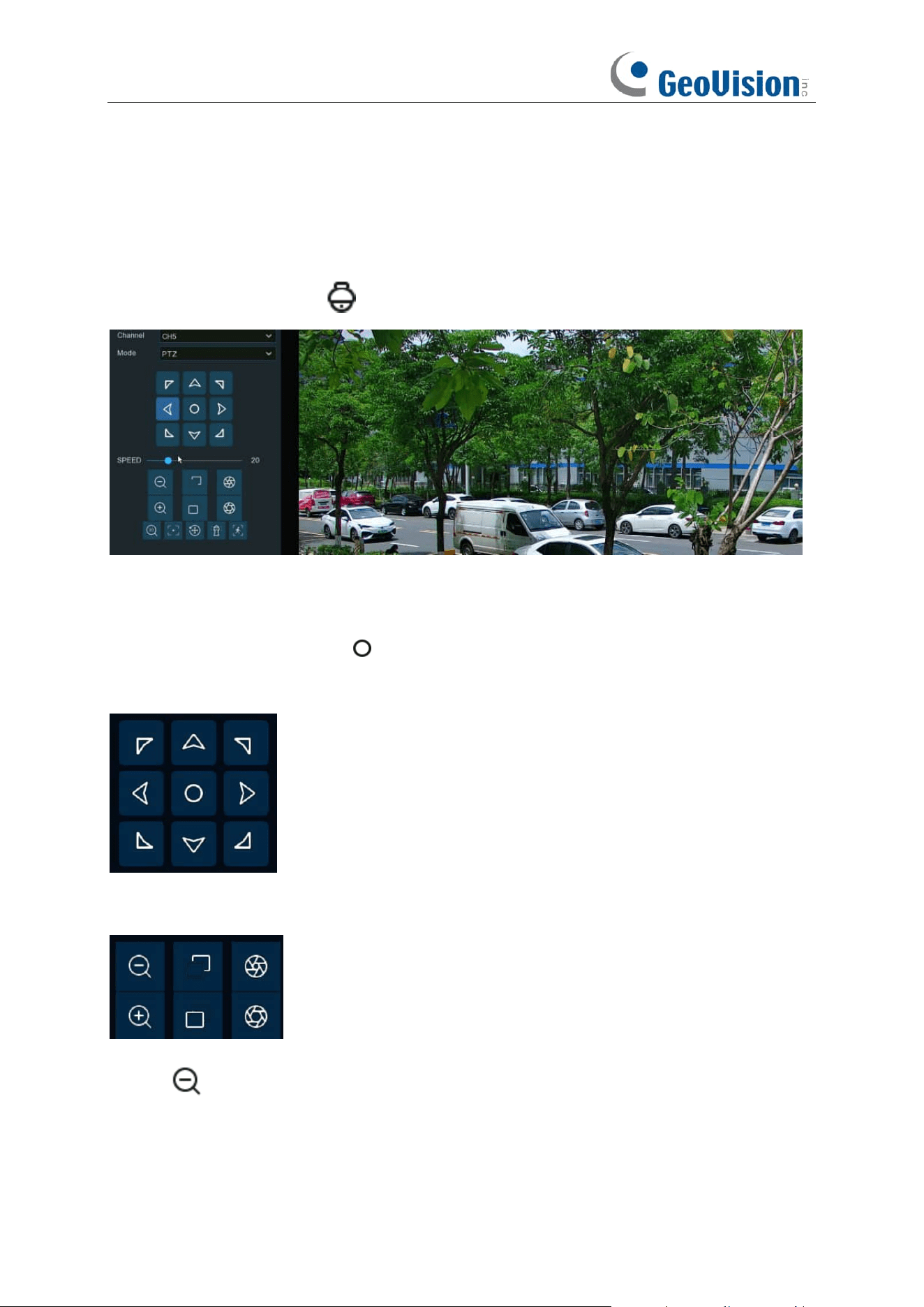
58
Restore:
Restore the camera to default status.
5.1.4.1.2 Controlling Your PTZ Camera
In live viewing, click the left button of your mouse on the PTZ camera to pop up the Camera Quick
Toolbar. Click the PTZ button to enter PTZ control panel.
Mode:
To control the PTZ camera by PTZ, Preset, Line Scan, Watch Mode, Tour and Pattern
Scan.
Directional Buttons:
Click and hold the directional buttons to move the camera in the direction
selected. Click the middle button to continually rotate the camera towards the left (click the
any directional button to stop). If you want to change the rotation speed, you need to stop the
rotation firstly, and then start again after changing the speed.
Speed:
Adjust the speed control to alter how fast or slow the camera will pan or tilt. Move the
slider to decrease or increase the speed.
Lens Control Buttons:
To control the optical zoom, focus length and iris of the lens.
➔ Single click on the button, the lens will perform one movement to zoom out the
image and auto focus. Click and hold on the button to perform continuous movements till
you release the mouse button.

59
➔ Single click on the button, the lens will perform one movement to zoom in the image
and auto focus. Click and hold on the button to perform continuous movements till you
release the mouse button.
➔ Click and hold the button to decrease the focal length.
➔ Click and hold the button to increase the focal length.
➔ Click to reduce the iris value, image will get darker.
➔ Click to increase the iris value, image will get brighter.
5.1.4.1.2.1 Controlling PTZ
In this section, you're able to control the Pan/Tilt/Zoom and more.
1. Select PTZ mode.
2. Click the directional buttons to move the camera
3. To adjust the speed to pan or tilt.
4. To control the optical zoom, focus and iris of the lens.
5. Using functional buttons:
➔ 3D PTZ control. After clicking on this button, you're able to control the pan/tilt/zoom
directly on the live view screen.
⚫ Click on any point in the image, and then the image will be centered on the clicked point.
⚫ Drag: You can zoom in or zoom out the image by dragging your mouse on the image:
Click on the image and hold the mouse to drag a rectangle from point A to point B, the camera will
zoom in to get the objects closer.
Click on the image and hold the mouse to drag a rectangle from point B to point A, the camera will
zoom out to get the objects farther.
➔ Auto focus.
➔ Load default values. All the parameters you set will be lost and restored to default
values.
➔ Start or stop Watch Mode. See more on 5.1.4.1.2.3 Watch Mode.
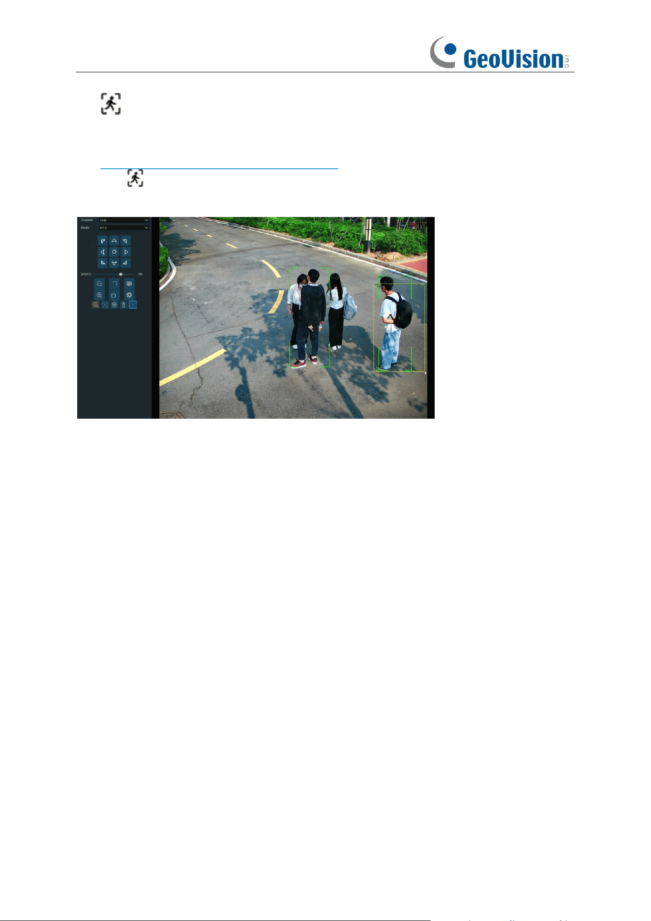
60
➔ If your PTZ camera supports auto tracking on the movement of human beings, you're
able to control the tacking by manual if there are several detected targets to let the camera
focused on a certain target. Before using this function, please make sure you have already
activated the human detection function and enable the PTZ auto tracking function, view in
5.4.1.2. PD & VD (Human & Vehicle Detection).
Click the button, and then click and hold your mouse on the live view screen, drag a rectangle
with yellow line to frame the targeted person. The camera will focus on the select person till he/she
disappears from view.
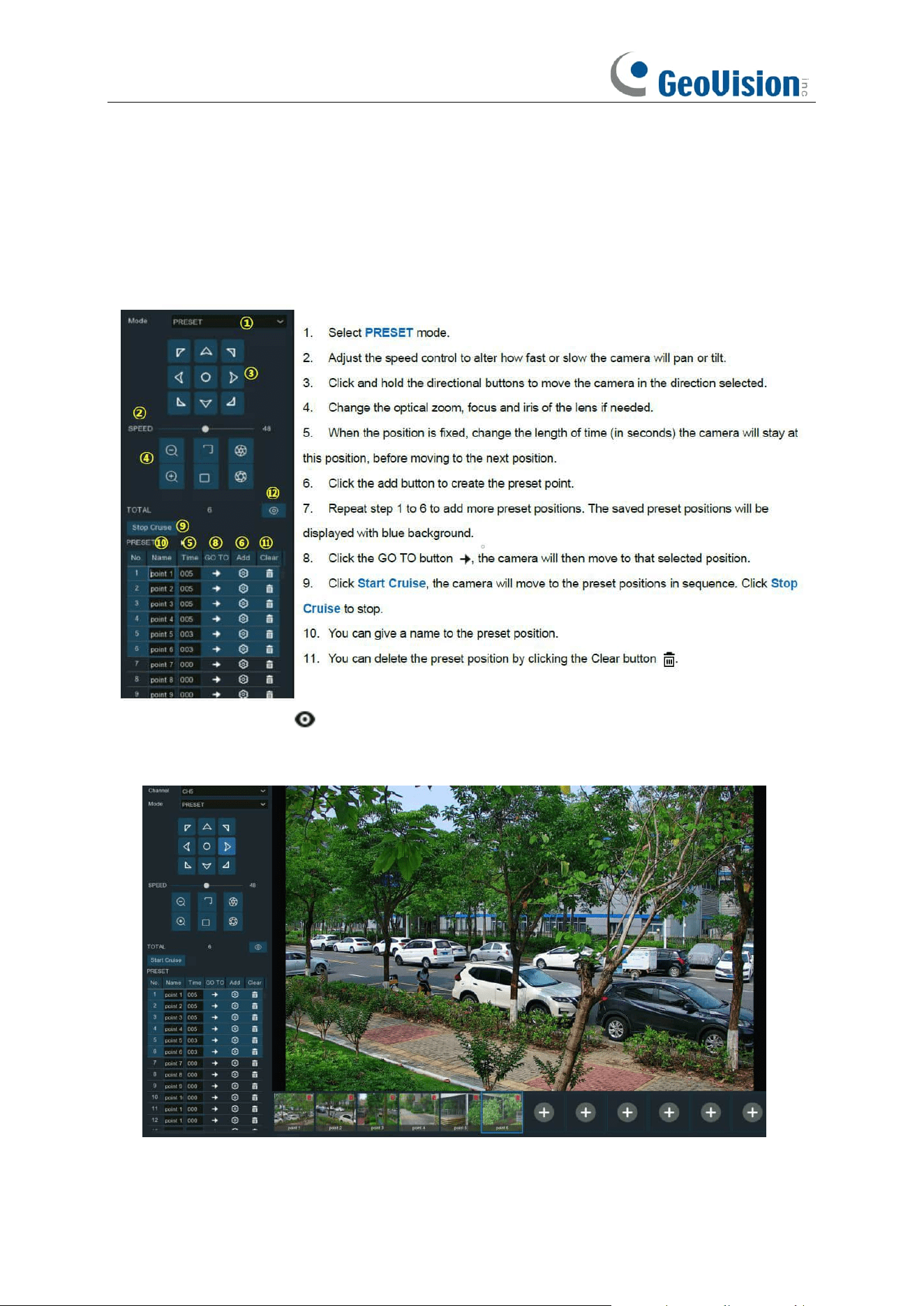
61
5.1.4.1.2.2 Preset Position
In this section, you're able to configure the preset positions. A preset position is a particular
position within the image that you would like the camera to focus on. Up to 255 different preset
positions can be created.
12. Click the visual icon , you will see the thumbnail of preset position is displayed on the
bottom of the live view image. You can go to, delete or add a preset position in the visual
interface.
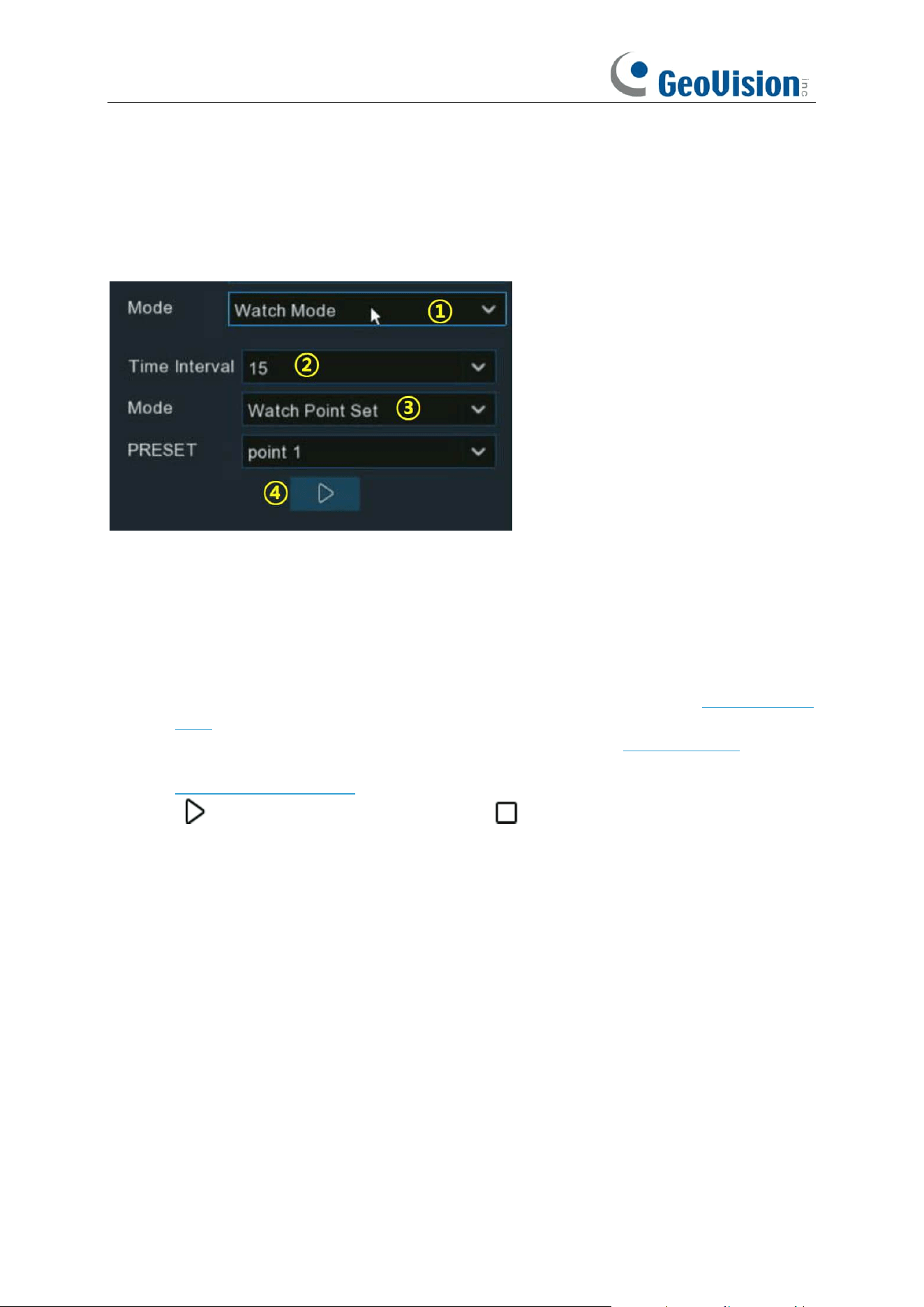
62
5.1.4.1.2.3 Watch Mode
Watch mode allows the camera to perform a preset action when there is no any operation to the
camera, such as moving to a preset position, starting cruise, etc.
1. Select the Watch Mode.
2. Set the time interval. It means the length of time that must elapse before the watch mode is
taken action. For example, the watch mode is activated and the interval is set to 15, the
camera will perform the watching action if there is no operation to the camera in 15 seconds.
3. Choose the action when the watch mode is activated:
➔ Default Cruise: The camera will be continually rotated towards the left
➔ Preset Position: The camera will be moved to a selected preset position and stay.
➔ Line Scan: The camera will be implemented the Line Scan. See more on 5.1.4.1.2.4 Line
Scan.
➔ Tour: The camera will be implemented the Tour. See more on 5.1.4.1.2.5 Tour.
➔ Pattern Scan: The camera will be implemented the Pattern Scan. See more on
5.1.4.1.2.6 Pattern Scan.
4. Click button to start the Watch Mode. Press button to stop.
5.1.4.1.2.4 Line Scan
Line Scan allows the camera to automatically cruise between position A to position B horizontally.
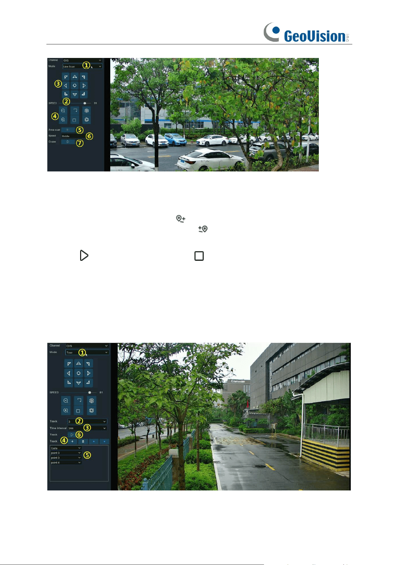
63
1. Select Line Scan mode.
2. Adjust the speed control to alter how fast or slow the camera will pan or tilt.
3. Click and hold the directional buttons to move the camera in the direction selected.
4. Change the optical zoom, focus and iris of the lens if needed.
5. When the first position is fixed, click button to record this position A. Repeat step 3 & 4 to
move the camera to another position. Click to record the position B.
6. Adjust the cruise speed.
7. Click button to start Line Scan. Press button to stop.
5.1.4.1.2.5 Tour
With the Tour function, you're able to configure maximum 4 tracks of auto cruise by choosing
different preset positions.
1. Select Tour mode.
2. Select a track. Maximum 4 tracks available.
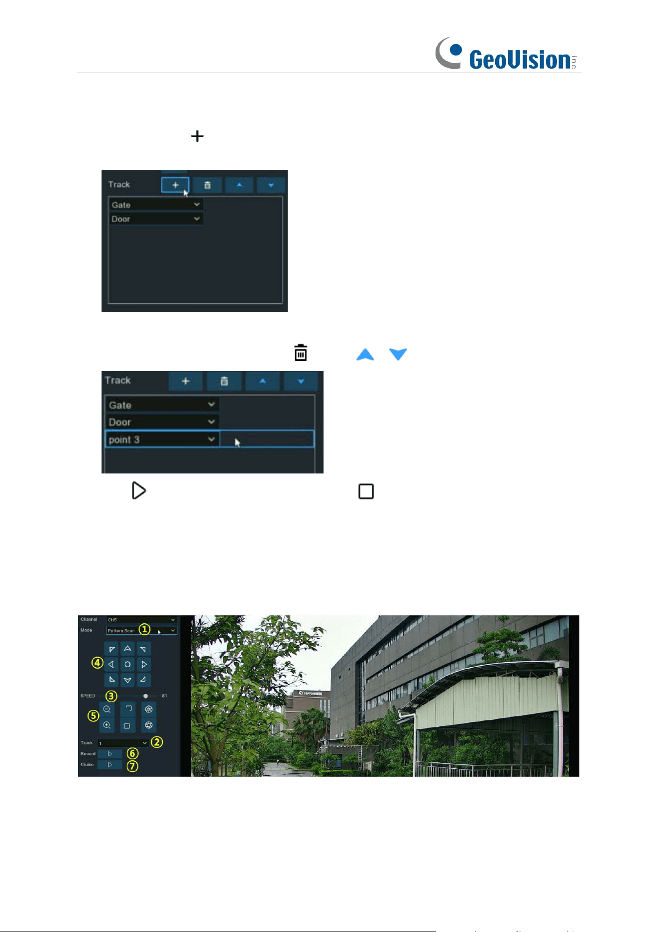
64
3. Set the time interval. It means the length of time that the camera will stay in each preset
position.
4. Click add button , a position box will be added and displayed in the position list. Click the
box to choose a preset position. Maximum 32 positions can be added to a track.
5. Click on the blank area on the right side of the position box, and then delete the preset
position by clicking the delete button , or click / button to change its sequence.
6. Click button to save and start the tour. Press button to stop.
5.1.4.1.2.6 Pattern Scan
This is a function that allows the camera to implement auto cruise by following a pre-record route.
1. Select Pattern Scan mode.
2. Select a track. Maximum 4 tracks available.
3. Adjust the speed control to alter how fast or slow the camera will pan or tilt.
4. Click and hold the directional buttons to move the camera in the direction selected.
65
5. Change the optical zoom, focus and iris of the lens if needed.
6. When the start position is fixed, click button to start recording. Repeat step 4 & 5 to adjust
the position. Press to finish the recording of route.
7. Click button, the camera will be moved exactly same as the route which was recorded in
step 6, including zoom, focus, direction. Press to stop.
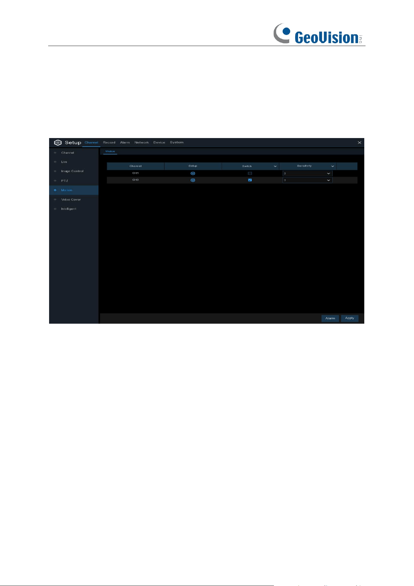
66
5.1.5 Motion
This menu allows you to configure motion parameters. When motion has been detected
by one or more cameras, your NVR will alert you to a potential threat at your home. It does this by
sending you an email alert with an attached image from the camera to use as a reference (if this
option is enabled) and/or sending push notifications via the mobile app.
Switch
: Enable or disable motion detection.
Sensitivity
: Set the sensitivity level. Level 1 the lowest sensitivity level while level 8 is the highest
sensitivity level.
SMD by Recorder: Used for the cameras that do not support intelligent motion detection.
SMD by Camera: Used for the IP cameras that support intelligent motion detection. There are 4
types available: Motion, Pedestrian, Vehicle, and Pedestrian & Vehicle.
➔
Motion:
The camera will detect all motion events, including movements of human beings,
vehicles, animals, trees, etc.
(Note: Some models of IP cameras support this function. The SMD by Recorder function will be
grayed out and unavailable after connecting to this model of IP camera.)
If your camera or NVR supports smart motion detection (SMD), you'll be able to choose below
advanced motion detection targets:
➔
Pedestrian:
The camera only alert when the movements of human beings are detected.
➔
Vehicle:
The camera only alert when the movements of vehicles are detected.
➔
Pedestrian & Vehicle:
The camera only alert when the movements of human beings
and/or vehicles are detected.
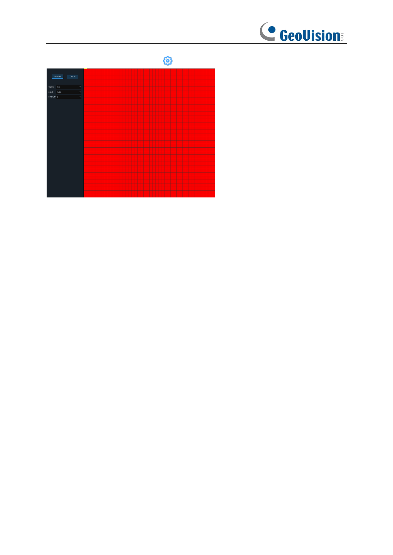
67
Motion Detection Area Setup
: Click icon into the setup page.
1. The whole screen is marked for motion detection (red blocks) as default. Optionally click
"Clear All" to delete all the default detection area.
2. To create a new detection area, press and hold the left mouse button to select the cell or
square that you want to start at, then click and drag to select the area that you want to create.
Release the mouse to finish.
3. Multiple areas can be created. Each cell or square can be enabled to detect motion. The
same action also applies when deleting an area.
4. Movement outside of the motion detection areas won't be detected therefore will not trigger
recordings or event notifications.
5. Adjust the sensitivity if required, then right-click the mouse to exit.
6. Click "
Apply
" to save changes made.
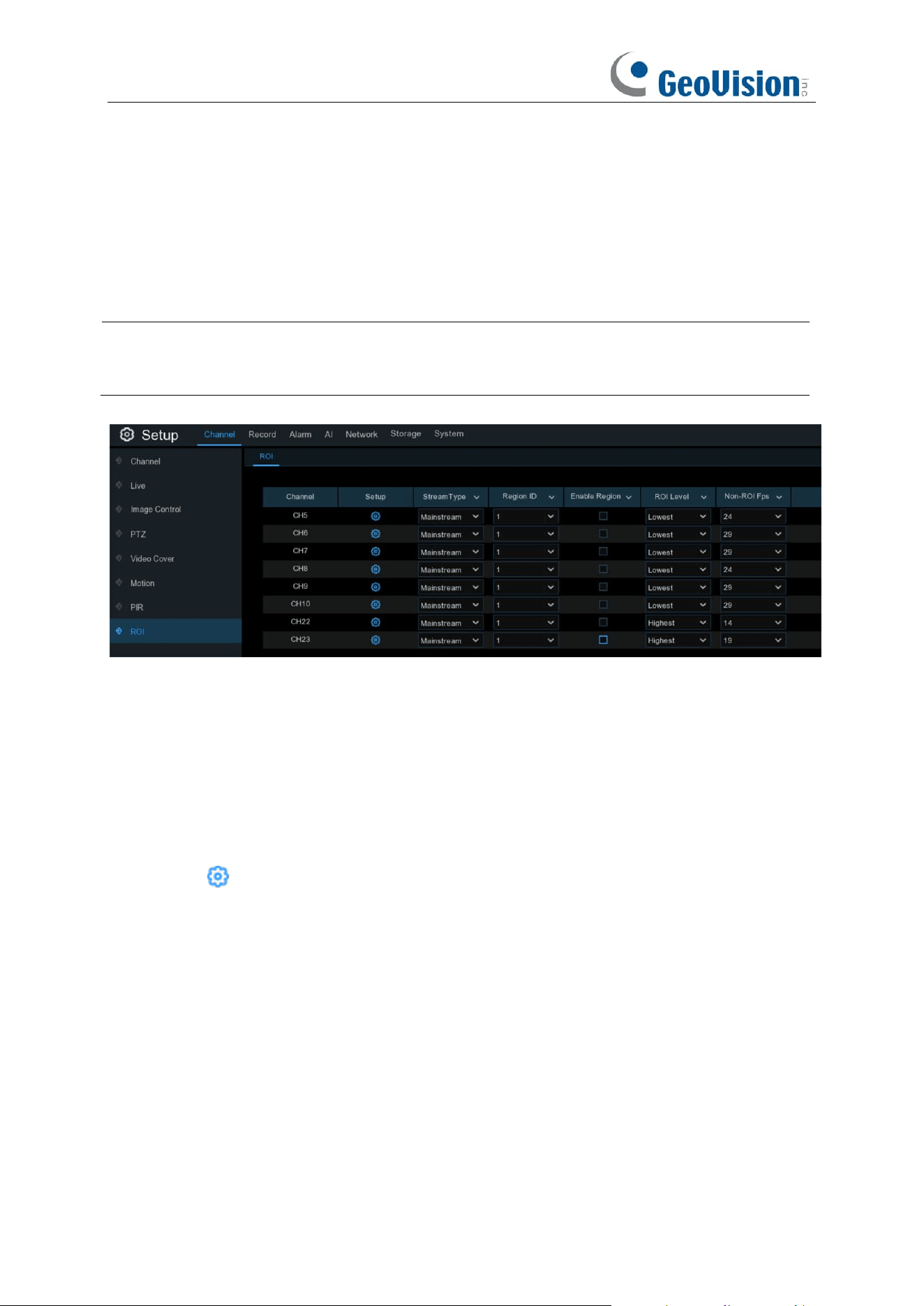
68
5.1.6 ROI
Regions of Interest (ROIs) are selected regions for special attention in the video area. This
function aims to improve the image encoding quality of the selected regions and reduce the
encoding quality outside the selected regions, so as to ensure the image sharpness of the regions
for special attention under the condition of constant bitrate.
Note: This function is only applicable when the NVR is connected to the following GV-IP
cameras: RBL5800 / RBL5811 / REB5800 / RFER12700. It cannot be used with the H.264 and
H.265 encoding types at the same time.
Stream Type: Select the stream type to set.
Region ID: Select the region ID to be set. You can set at most eight region IDs.
Enable Region: Used to set whether to enable the selected regions: The Region ID and Enable
Region parameters of the selected regions are mutually independent and need to be configured
separately.
ROI Level / Video Quality: Used to set the image quality of the selected regions. The higher the
quality is, the clearer and the smoother the image is.
Non-ROI Fps / RONI Frames: Used to set the frame rate outside the selected regions.
Setup: Click to open the setting page.
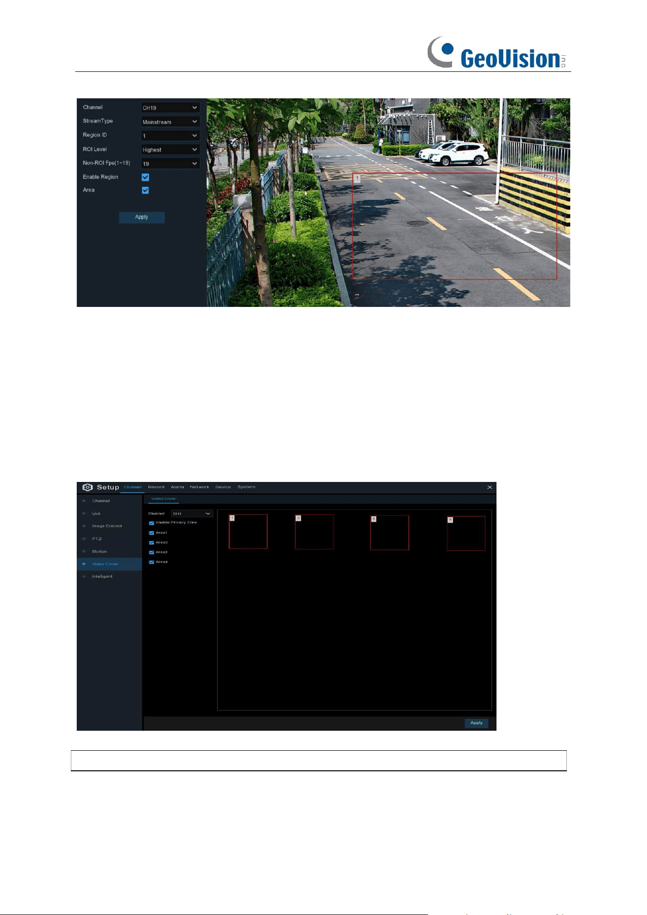
69
Area: Used to set whether to enable ROI selection. The configuration takes effect after you click
Apply.
5.1.7 Video Cover / Privacy Zone
This menu allows you to create privacy zone(s) if you want to partially cover some certain part of
the image. You can create up to 4 privacy zones in any size and location on the camera image.
Enable the Privacy Zone, and choose how many zones you need. The zone(s) appear as “red
box”. Click the edge of the red box and drag it to any size to create a privacy zone.
Note:
The areas of privacy zones set will be invisible in both live view & recording video.
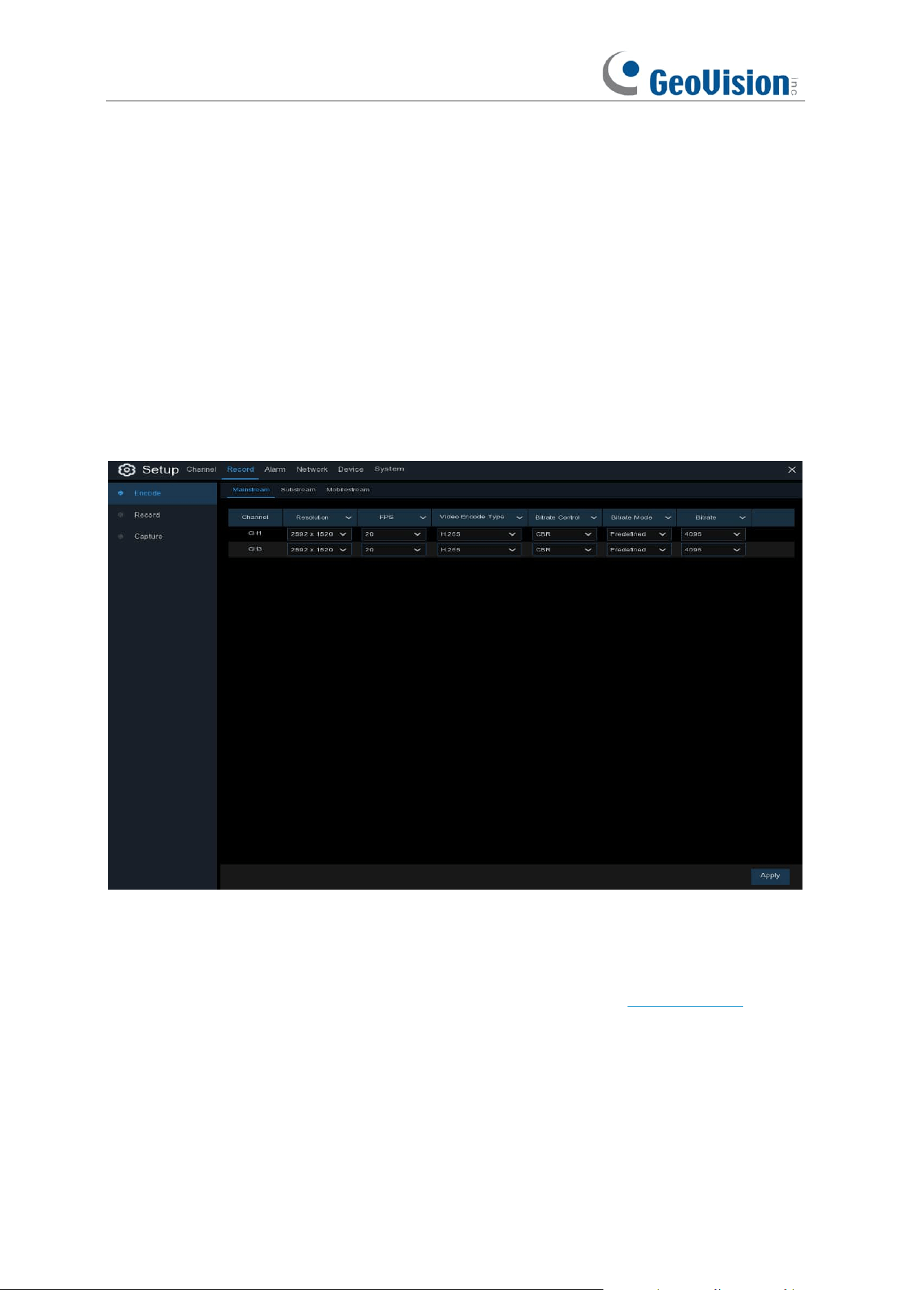
70
5.2 Record
The recording configuration options are available in the Record and Capture menus accessible
from the Main Menu. From here, you can access and change the recording frame rate & resolution
and recording schedule for each camera connected. You can also enable and set a schedule for
your NVR to take a snapshot each time when an event occurs.
5.2.1 Video Encoding
This menu allows you to configure the recording video or network transmission picture quality.
Generally, Mainstream defines the recording video quality which will be saved in the HDD;
Substream defines the video quality which is being viewed via remote access, for example web
client & CMS; Mobilestream defines the video quality which is being viewed via remote access via
mobile devices.
Resolution
: This parameter defines how large the recorded image will be.
FPS
: This parameter defines the number of frames per second the NVR will record.
Video Encode Type / Encoding Format:
For IP camera only. NVR supports H.264 IP camera
only. If you choose H.265, live view screen of the IP channel will display “Decoding Failed”.
Bitrate Control / Encoding Mode
: Select the bitrate level. For a simple scene, such as a gray
wall is suitable constant bitrate (
CBR
). For more complex scene, such as a busy street is suitable
variable bitrate (
VBR
).
Bitrate Mode / Config Mode:
If you want to set the bitrate by yourself, then choose
User-defined
mode. If you want to select the predefined bitrate, choose
Predefined
mode.
Bitrate:
This parameter corresponds to the speed of data transfer that the NVR will use to record
video. Recordings that are encoded at higher bitrates, will be of better quality.
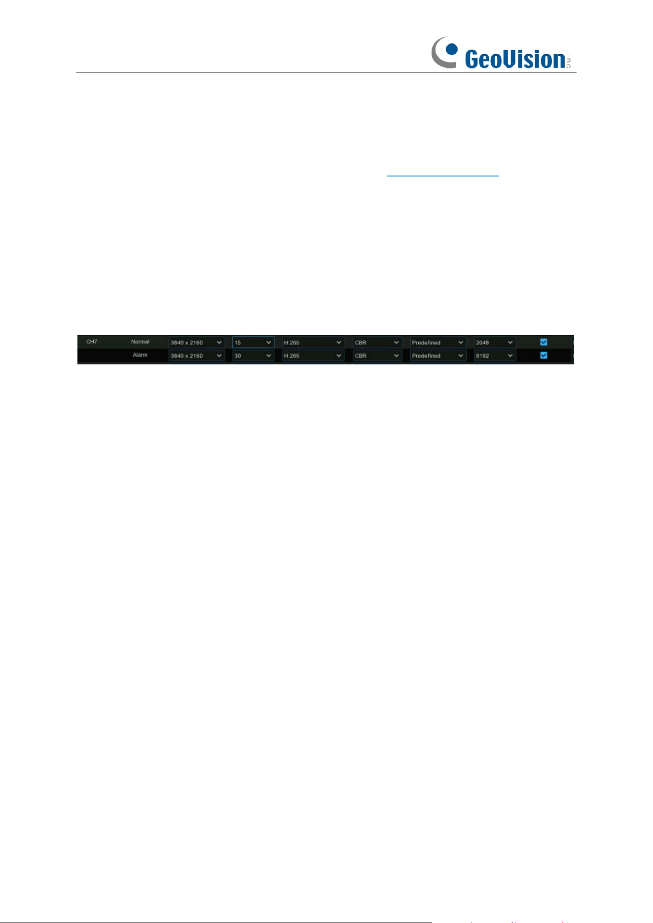
71
Video Quality: Available for VBR only, you can select the recording quality that will define the
variable bitrate used, from lowest to highest.
Audio: If your camera has built-in microphone or external audio input device, you're able to record
the audio streaming together with the video streaming. Click the checkbox to disable or enable.
Make sure you have already enabled the Audio streaming in 5.2.2. Audio Encoding if you want to
record the audio streaming.
I Frame Interval: This configures the number of partial frames that occur between full frames
(I-Frames) in the video stream. For example, in a scene where a door opens and a person walks
through, only the movements of the door and the person are stored. The stationary background
that occurs in the previous partial frames are not encoded. As the I-Frame increases, the number
of partial frames also increases. Higher values are only recommended on networks with high
reliability, otherwise leave the default selection.
ETR: If your camera supports ETR function, it allows you to set independent video streaming for
normal and alarm triggered recording.
For example, you can decrease the frame rate and bitrate to reduce the recording file size in
normal recording, and increase the frame rate and bitrate to have clearer and more fluent camera
images when an alarm event occurs. The ETR options are available for mainstream only.
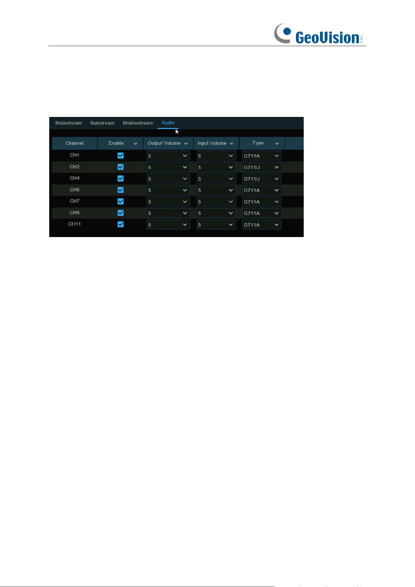
72
5.2.2 Audio Encoding
If your camera has built-in microphone or external audio input device, you're able to activate the
audio stream, define the input/output volume, and select the audio encode type.
Enable: To turn on or turn off the audio streaming.
Output Volume / Local Audio Volume: To choose the audio output volume.
Input Volume: To choose the audio input volume.
Type: To choose the audio encoding codec.
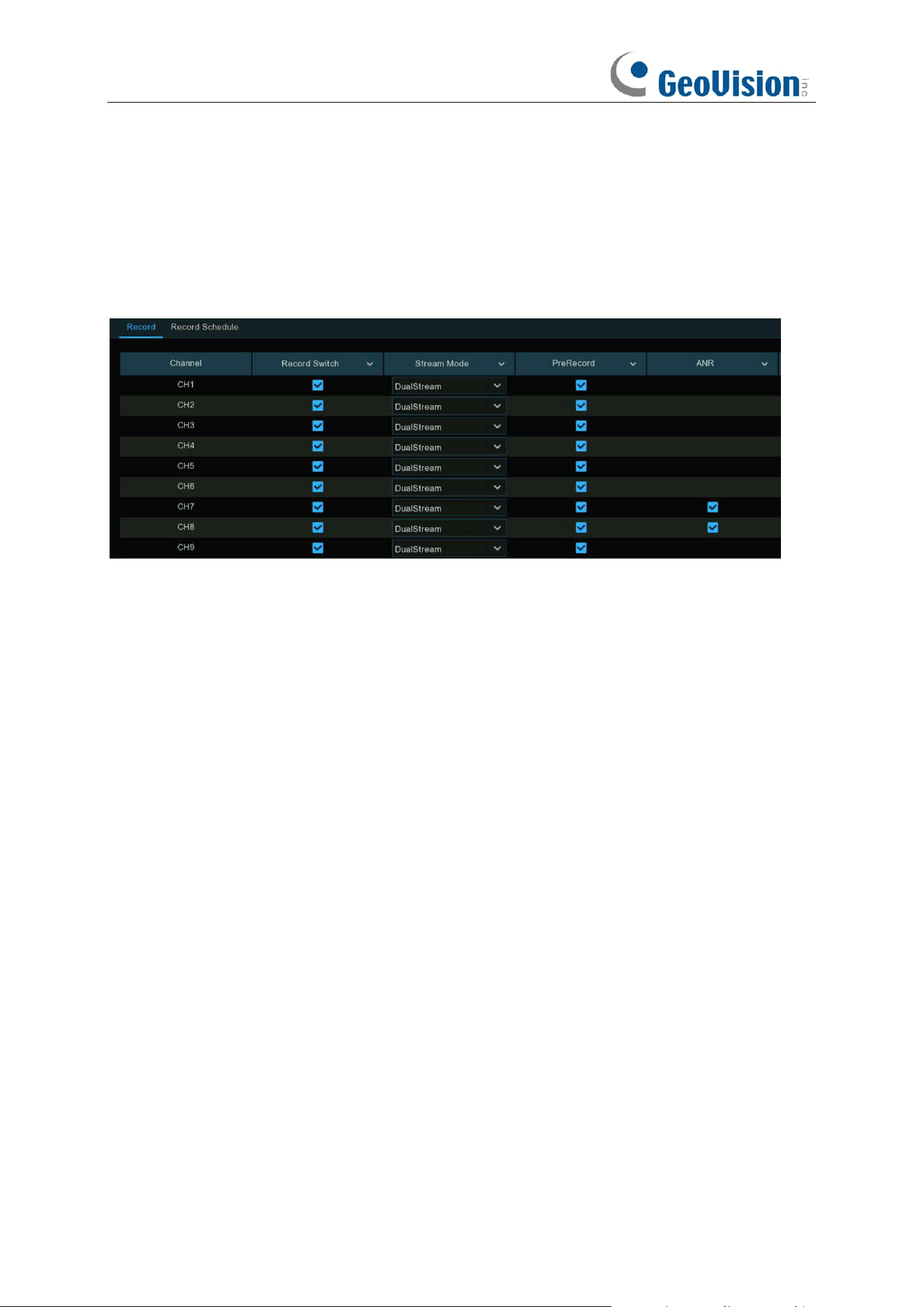
73
5.2.3 Record
This menu allows you to configure the channel recording parameters.
5.2.3.1 Recording Configuration
Record Switch
: Check to enable the recording in this channel.
Stream Mode
: Choose the recording quality. If you choose Dualstream, the system will record in
both Mainstream & Substream.
PreRecord
: If this option is enabled, the NVR starts recording a few seconds before an alarm
event occurs. Use this option if your primary recording type is motion or I/O alarm based.
ANR: Generally, videos are stored in the NVR when network connection is normal between the
NVR and cameras. With ANR (Automatic Network Replenishment) function, the camera would
start continuous recording and store videos in SD card instead when the connection is lost. Once
the network is restored, the video recordings will be sent back to NVR's storage. It is
recommended to enable ANR if your camera supports this function.
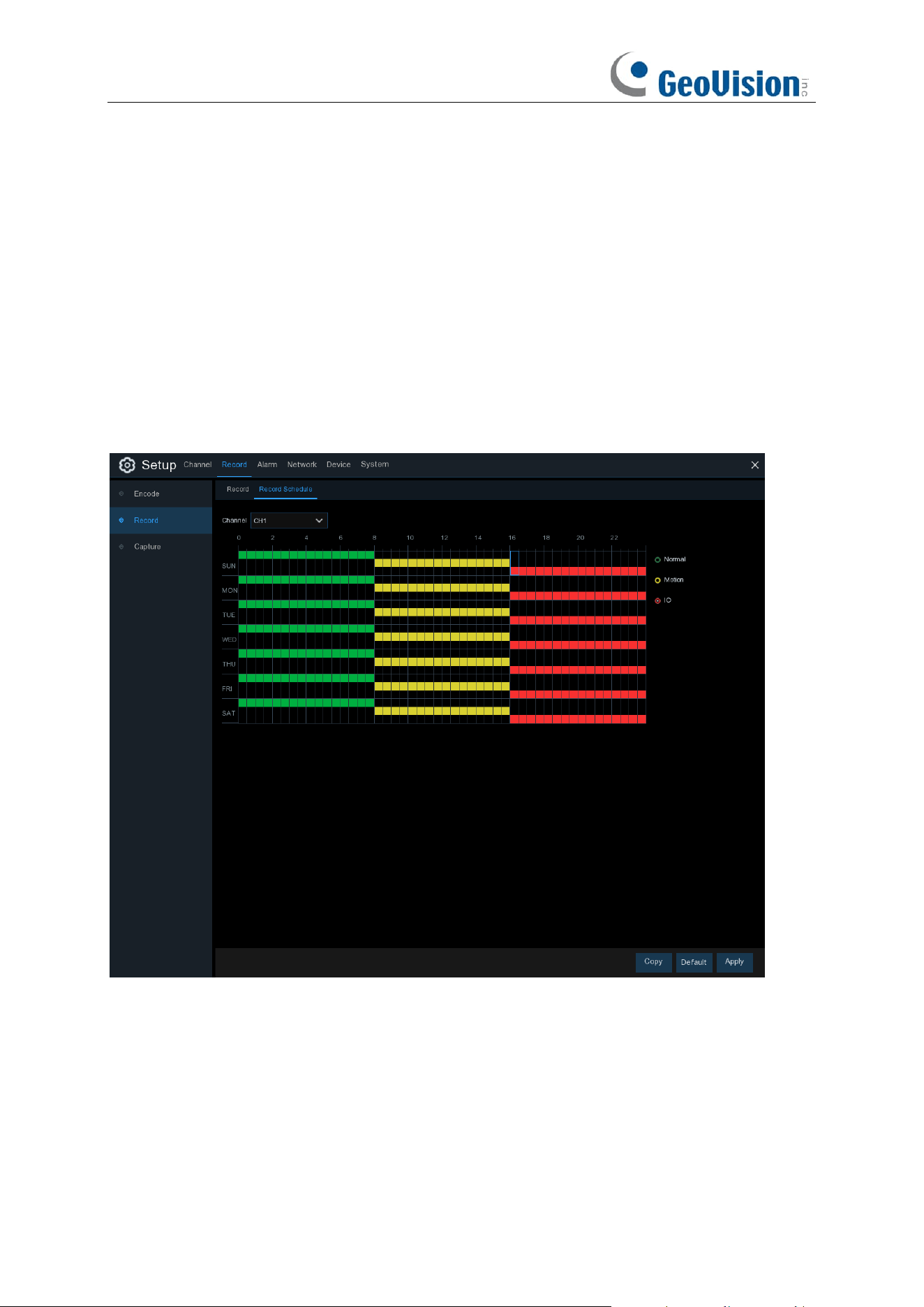
74
5.2.3.2 Record Schedule
This menu allows you to specify when the NVR records video and defines the recording mode for
each channel. The recording schedule lets you set up a schedule like, daily and hourly by normal
(continuous) recording, motion recording, I/O alarm recording. To set the recording mode, click
first on the mode radio button (Normal, Motion, IO), then drag the cursor to mark the slots. The
recording schedule is valid only for one channel. If you want to use the same recording schedule
for other channels, use
Copy
function. Click
Apply
to save your settings.
Channel
: Select the channel to set its recording parameters.
Normal
: When the time slot is marked green, this indicates the channel performs normal recording
for that time slot.
Motion
: When the time slot is marked yellow, this indicates the channel records only when a
motion is detected during that time slot.
IO
: When the time slot is marked red, this indicates the channel records only when the sensor is
triggered during that time slot.
No Record
: A time slot marked black means that there is no recording scheduled for the time slot.
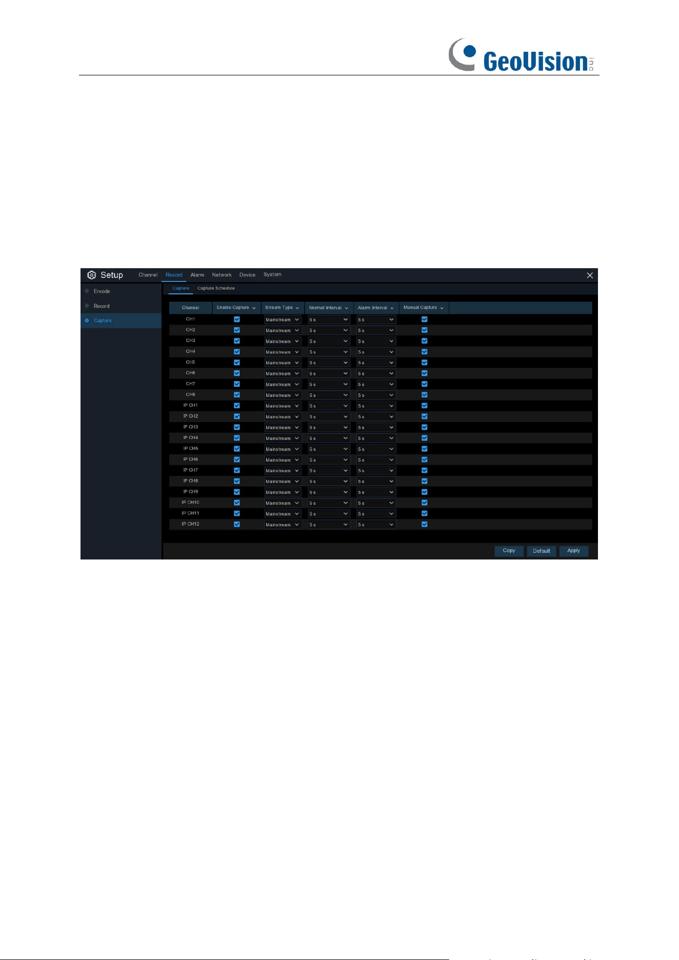
75
5.2.4 Image Capture
You can enable and set a schedule for your NVR to take a snapshot each time an event occurs. It
helps to find alarm events quickly and can also be used for timelapse photography.
5.2.4.1 Capture
Auto Capture: When enabled, your NVR will take a snapshot each time an event occurs.
Enable Capture
: Enable or disable automatic capturing on the channel.
Stream Type
: Select the image resolution by mainstream or substream.
Normal Interval
: Time interval to capture an image in normal recording.
Alarm Interval
: Time interval to capture an image when motion or IO alarm is triggered
Manual Capture
: Enable or disable manual capture in the channel
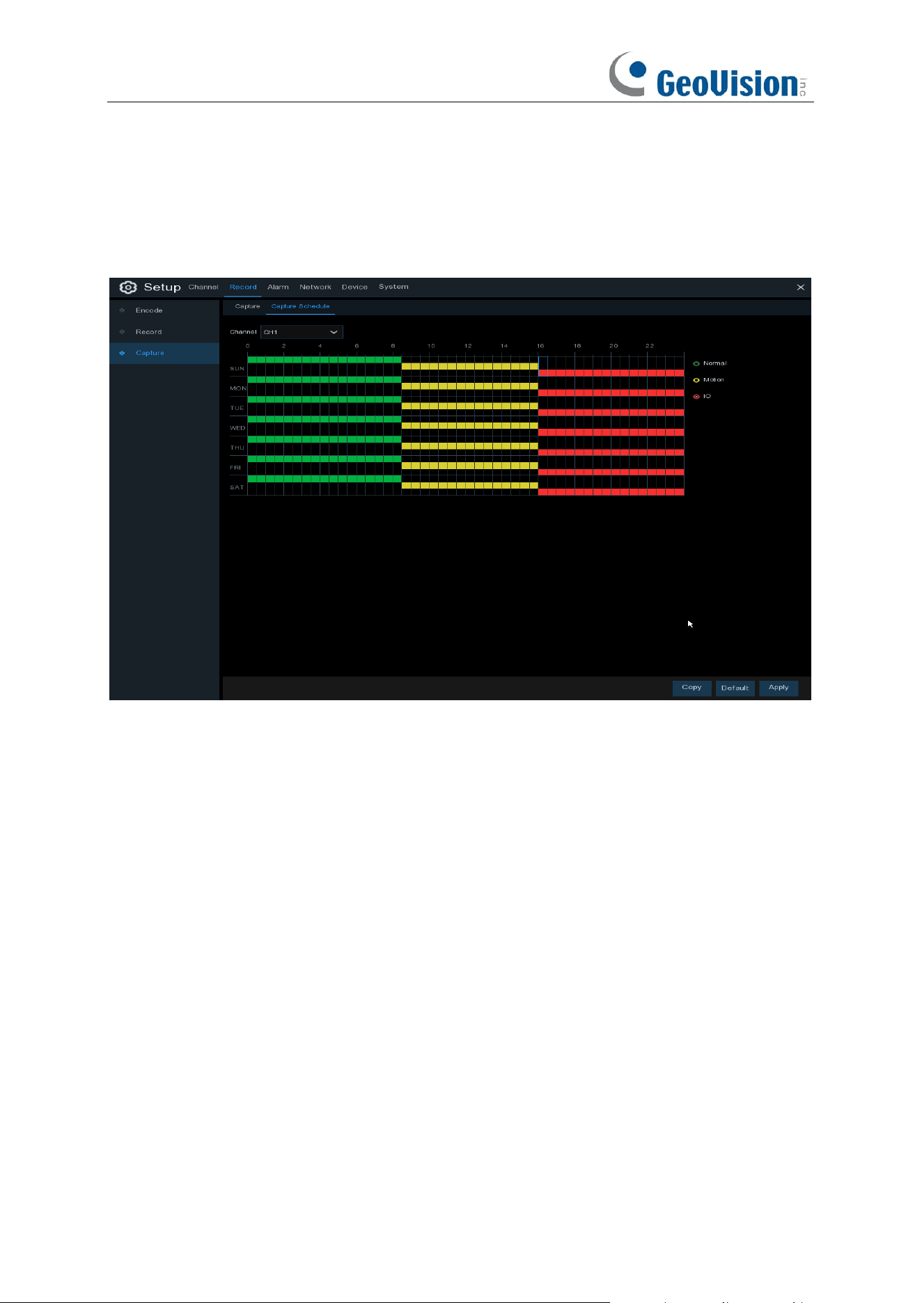
76
5.2.4.2 Capture Schedule
You must create a capture schedule so your NVR can take snapshots when an event has occurred
or if you want to take snapshots using a time interval (every 5 seconds, for example).
Channel
: Select the channel to set its capture parameters.
Normal
: When the time slot is marked green, this indicates the channel performs normal capture
for that time slot.
Motion
: When the time slot is marked yellow, this indicates the channel capture images only when
a motion is detected during that time slot.
IO
: When the time slot is marked red, this indicates the channel capture images only when the
sensor is triggered during that time slot.
No Capture
: A time slot marked black means that it won’t capture any images for the time slot, but
you can manually capture images if you enable the manual capture function in the channel.
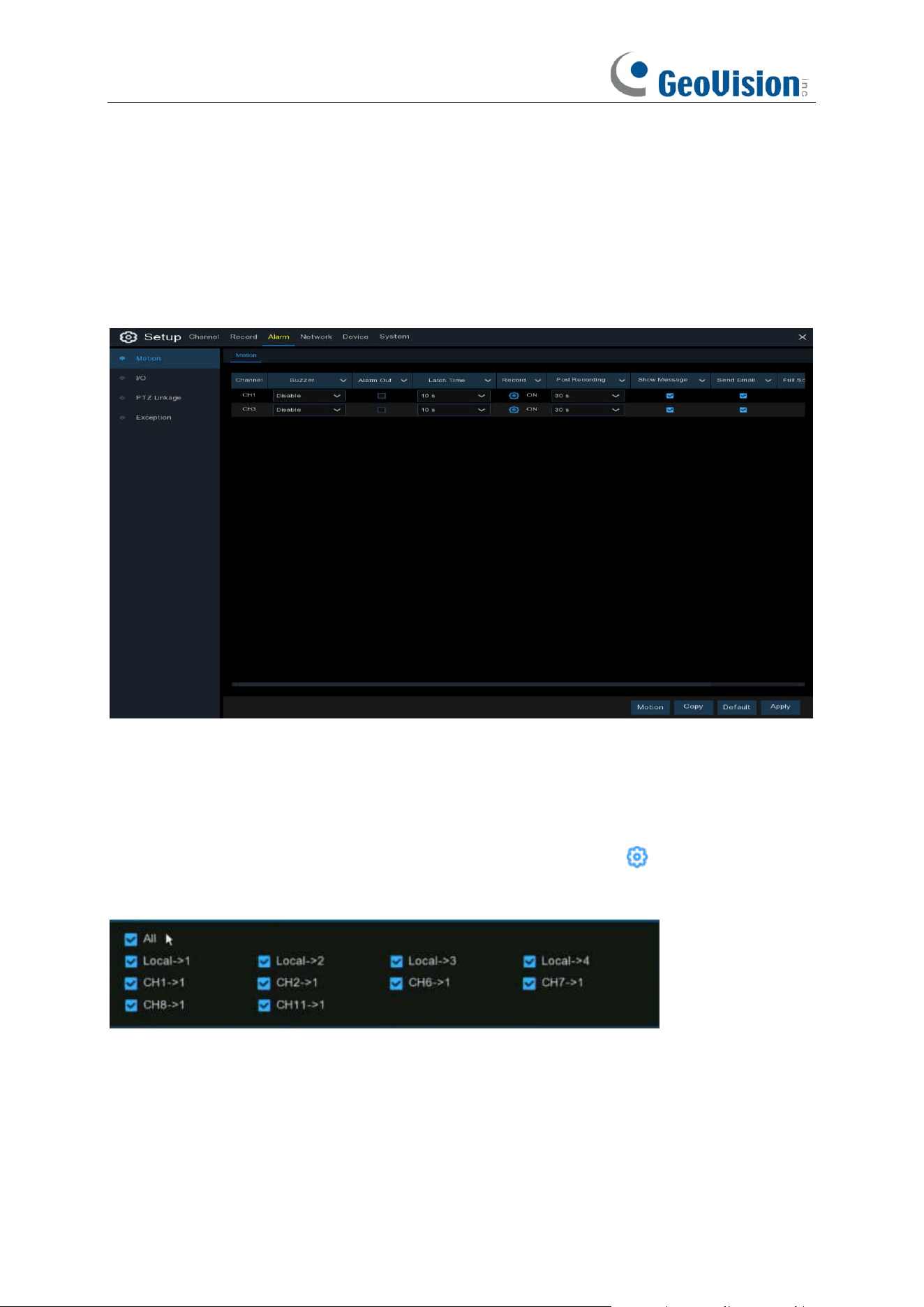
77
5.3 Alarm
In this section, you can configure the alarm parameters.
5.3.1 Motion
Click
Alarm
button to configure the motion detection alarm function:
Channel:
Channel name.
Buzzer:
The NVR can use its internal buzzer to emit an alarm tone. You can set the buzzer
duration in seconds when the motion is detected.
Alarm Out: If your NVR or IP camera supports to connect external replay output devices, the
system can send an alert message to the external alarm devices. Click button, to choose the
external alarm devices:
⚫
Local
: The external alarm devices connected to the NVR.
⚫
CHx ->
1
: The external alarm devices connected to IP cameras.
Latch Time
: To configure the external alarm time when motion is detected.
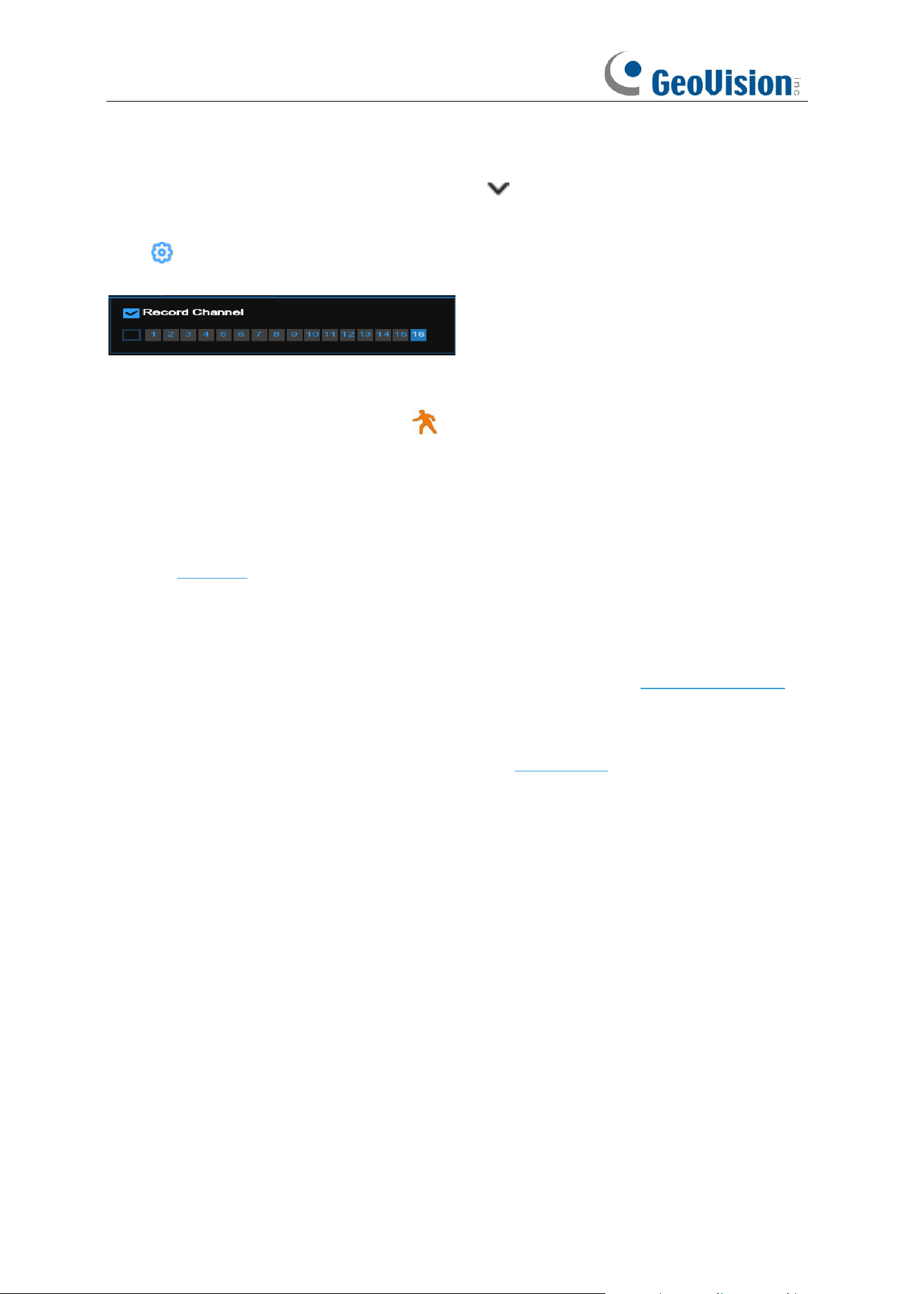
78
Record / Channel: This option instructs your NVR to trigger additional cameras to start recording
when motion is detected. Click the drop-down arrow to choose all channels to be recorded or
not.
Click icon and choose which channel you want to record when the motion detection is
triggered.
Post Recording
: You can set how long after an event occurs that the NVR will continue to record.
The recommended recording length is 30 seconds but it can be set higher up to 5 minutes.
Show Message
: Check the box to display
icon on the live view screen when the motion is
detected.
Send Email
: You can let the NVR to send you an auto-email when the motion is detected.
Full Screen
: If this function is enabled and a motion is detected in a channel, you will see that
channel in full screen.
FTP Upload
: To upload alarm images/videos to FTP server when motion is detected. To enable
FTP, see 5.6.3 FTP for details.
Picture/Video to Cloud: Click the checkbox to copy snapshots/videos to the cloud via Dropbox or
Google Drive when the detection is triggered.
Voice Prompts: If your NVR connects with a speaker, you can select a customized alert voice
when the detection is triggered. See how to add customized alert voice on 5.3.6 Voice Prompts.
Event push Platform: Click the checkbox, this type of message will be pushed to the client when
an alarm is triggered.
Motion: To configure the motion detection. See more on 5.1.5. Motion.
Default: Click "Default" to revert to default settings.
Copy: Use the "Copy" function to apply all settings to the other connected cameras.
Save: Click "Save" to save settings.
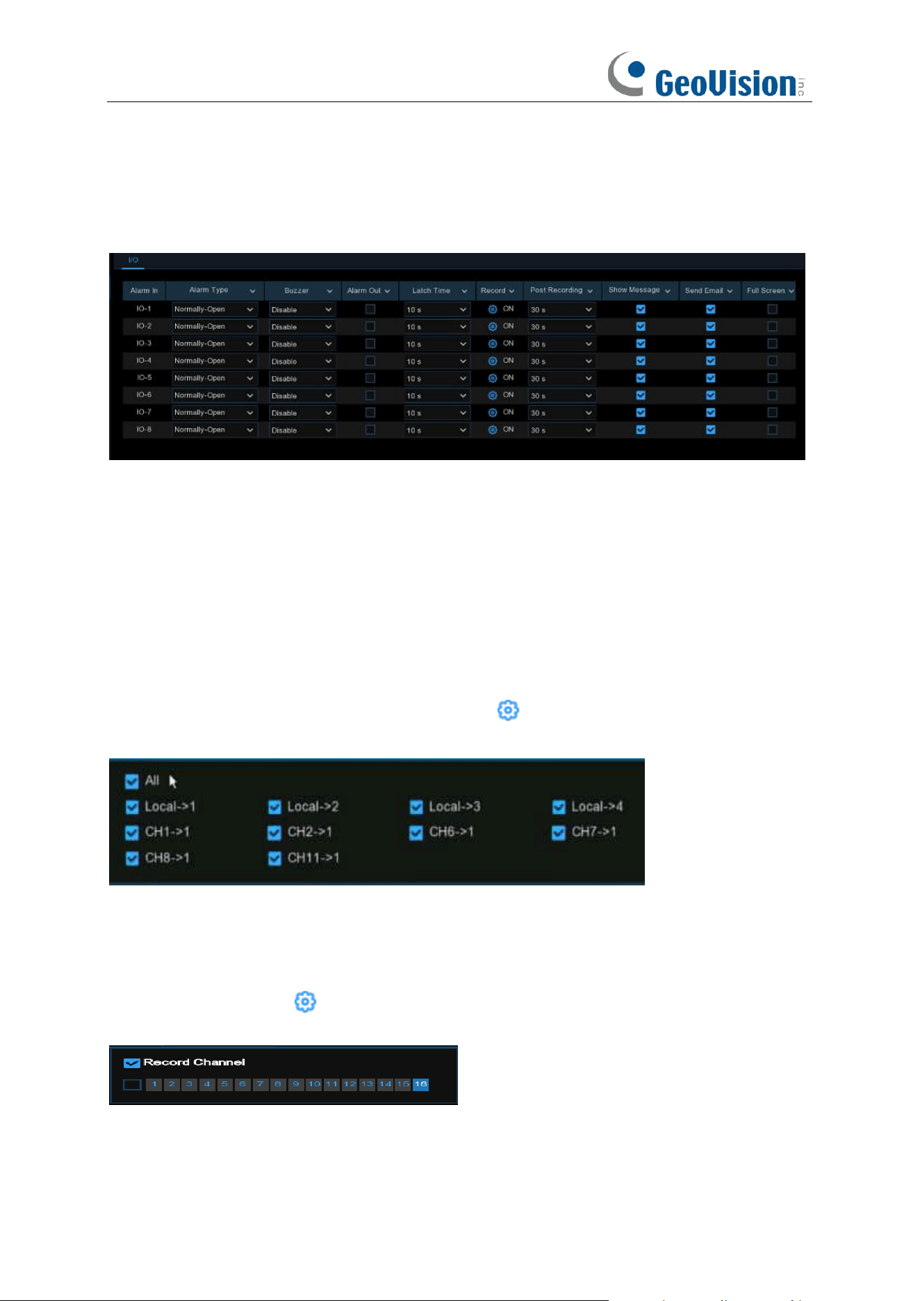
79
5.3.2 I/O Alarm
This is an optional function, it will appear if your NVR supports sensor I/O, you connect external
sensor I/O alarm devices to work with the NVR.
Alarm In:
I/O channel.
⚫
Local
: The external alarm devices connected to the NVR.
⚫
CHx<-
1
: The external alarm devices connected to IP cameras.
Alarm Type / IO State:
There are 3 types for your choice: Normally-Open, Normally-Close, and
OFF. Choose the one to match your sensor type, or choose OFF to close the sensor trigger
function.
Buzzer:
The NVR can use its internal buzzer to emit an alarm tone. You can set the buzzer
duration in seconds when a sensor is triggered.
Alarm out:
Tick to enable external alarm device to emit an alarm tone when a sensor is triggered.
If your NVR or IP camera supports to connect external replay output devices, the system can send
an alert message to the external alarm devices. Click button, to choose the external alarm
devices:
⚫
Local
: The external alarm devices connected to the NVR.
⚫
CHx->
1
: The external alarm devices connected to IP cameras.
Latch Time:
you can set how long the buzzer will sound when external sensor is triggered (10s,
20s, 40s, and 60s).
Record / Channel
: Click icon and choose which channel(s) you want to record when the
motion detection is triggered.
Post Recording:
You can set how long alarm record will last when alarm ends (30s, 1 minute, 2
minutes, 5 minutes).
Show Message:
Display the alarm messages on the screen when sensor is triggered.

80
Send Email:
Set to send email to specified email when sensor is triggered.
Full Screen:
When sensor is triggered, the corresponding channel will be switched to the full
screen mode.
FTP Picture/Video Upload
: To upload alarm images/videos to FTP server when I/O alarm is
triggered. To enable FTP, see 5.6.3 FTP
for details.
Picture/Video to Cloud: Click the checkbox to copy snapshots/videos to the cloud via Dropbox or
Google Drive when the detection is triggered.
Event push Platform: Click the checkbox, this type of message will be pushed to the client when
an alarm is triggered.
Voice Prompts: If your NVR connects with a speaker, you can select a customized alert voice
when the detection is triggered. See how to add customized alert voice on 5.3.6 Voice Prompts.
Default: Click "Default" to revert to default settings.
Copy: Use the "Copy" function to apply all settings to the other connected cameras.
Apply: Click "Apply" to save settings.
5.3.3 Intelligent Alarm
See 5.4.3.4 FD/PID/LCD/CC/CD/QD/RSD/SOD/Sound Detection/Video Tampering
Alarm/Intrusion/Region Entrance/Exiting Alarms for details.
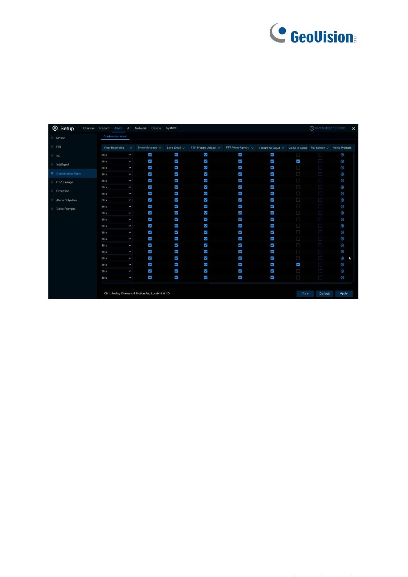
81
5.3.4 Combination Alarm
Combination Alarm function allows to set a combination of 2 alarm types. The NVR will only alert
when both the alarm types in the combination are triggered at the same time. This would help to
minimize the false alarm rate.
Channel: Channel name.
Enable Alarm / Switch: Enable enables combination alarm (combination alarm system
parameter of the channel configuration takes effect, alarm parameter set separately by the
channel is not effective). Disable does not enable combination alarm (combination alarm system
parameter configured by the channel is not effective, and event alarm system parameter set
separately by the channel does take effect).
Channel combination alarm is enabled. Combination Configure selects two alarm types. When
both alarms are triggered within the same time period, the notification information such as buzzer,
mail, push, upload is enabled. When only one of the alarms is triggered or when it is not triggered
or when alarms other than the combination occurs, email, push and other notifications will not be
sent. Two alarm types can be combined casually.
Buzzer:
The DVR can use its internal buzzer to sound an alarm. You can set the buzzer duration
(in seconds) when triggering a combined alarm.
Alarm out:
Check whether the external alarm device is triggered when the combination alarm is
triggered.
Latch Time:
You can set the duration of triggering the external alert devices (10s, 20s, 40s, and
1Min).
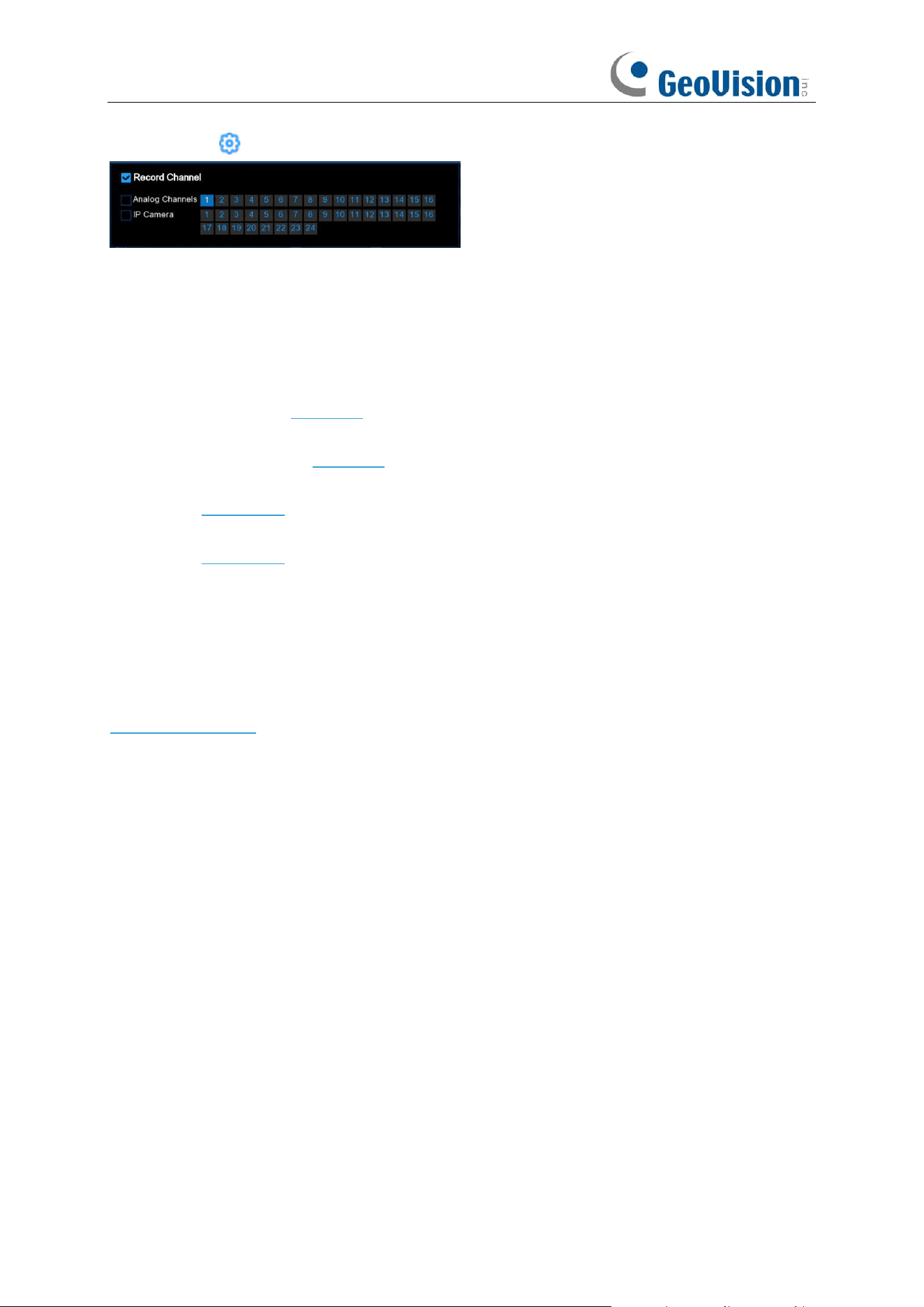
82
Record:
Click icon and select the channel to record when triggering the combination alarm.
Post Recording:
You can set the duration of continuous DVR recording after the event occurs.
The suggested recording time is 30 seconds, but can be set to up to 5 minutes.
Show Message:
Select this box to display the corresponding alert icon on the real-time display
screen when a combined alarm is detected.
Send Email:
Set to send email to specified email when sensor is triggered.
FTP Picture Upload:
To upload alarm images to FTP server when I/O alarm is triggered. To
enable FTP, please view 5.6.3 FTP.
FTP Video Upload:
To upload alarm videos to FTP server when
Combination alarm
is triggered.
To enable FTP, please view 5.6.3 FTP.
Picture to Cloud:
To upload alarm images to cloud storage when
Combination alarm
is triggered.
Please view 5.6.2 Cloud.
Video to Cloud:
To upload alarm videos to cloud storage when
Combination alarm
is triggered.
Please view 5.6.2 Cloud.
Full Screen:
When
Combination alarm
is triggered, the corresponding channel will be switched
to the full screen mode.
Event push Platform: Click the checkbox, this type of message will be pushed to the client when
an alarm is triggered.
Voice Prompts: Voice prompts, when triggering Combination alarm, the audio file imported by
the voice prompt (requiring IPC to support the voice prompt function) can be visible for details
5.3.7 Voice Prompts.
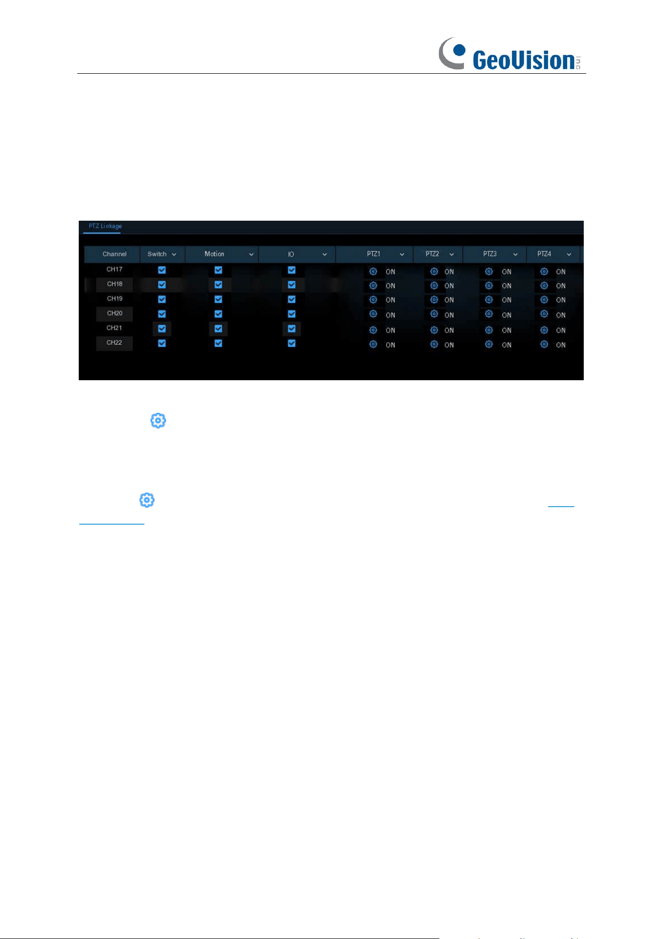
83
5.3.5 PTZ Linkage
If you had connected the PTZ cameras, you can set the linkage between PTZ cameras and Motion
Alarm and/or external I/O sensor alarm. With the linkage function, you can turn your PTZ cameras
focus to the preset point when a motion or I/O alarm happens.
Switch
: Enable or disable the PTZ linkage function.
Alarm: Click button to choose the alarm source to enable the PTZ linkage function when the
selected alarm occurs.
Motion:
Motion detection alarm will trigger the PTZ linkage function it is checked.
IO:
IO alarm will trigger the PTZ linkage function it is checked.
PTZ:
Click icon to associate the PTZ cameras with preset points. View preset point at
5.1.4
PTZ control
.
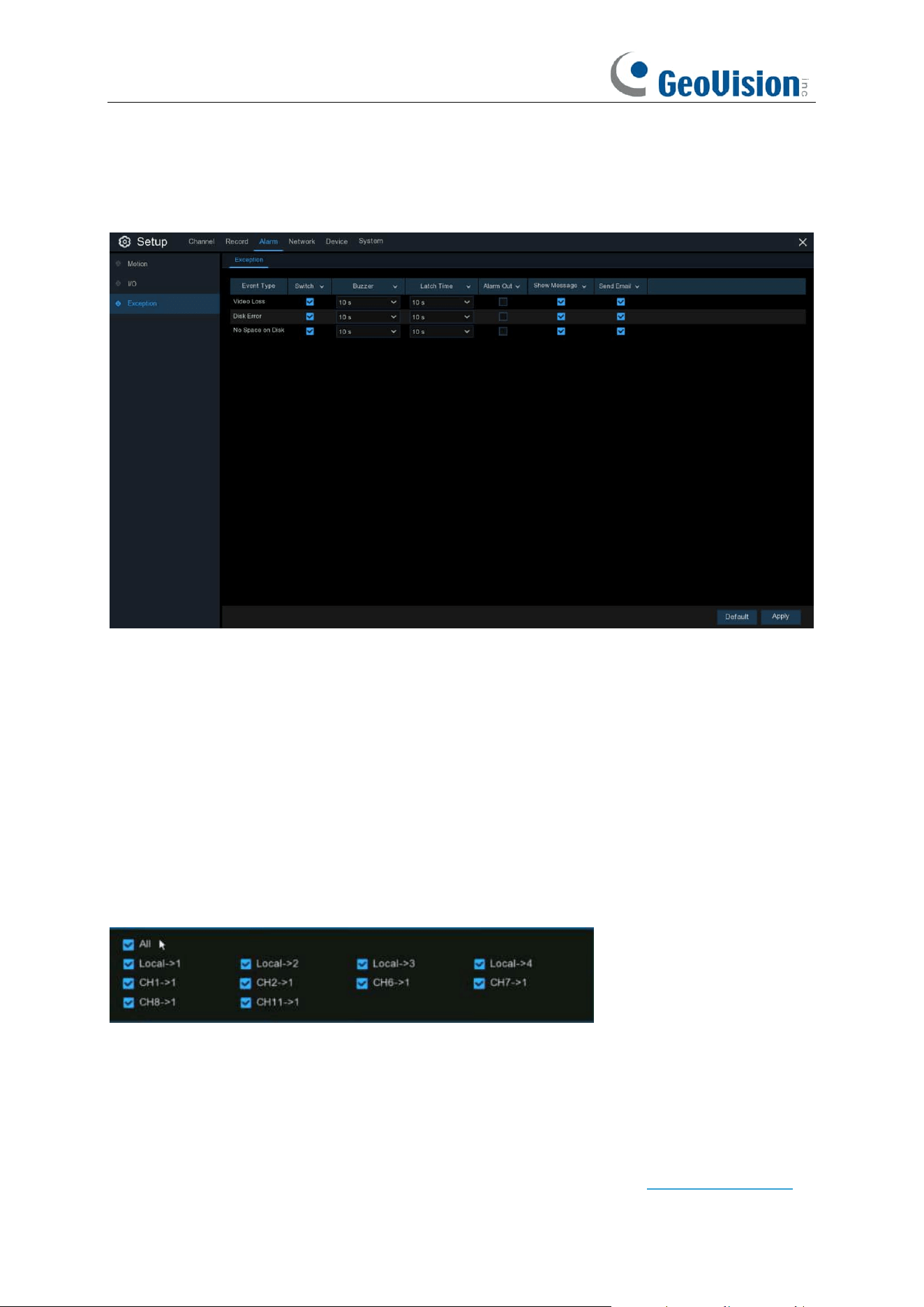
84
5.3.6 Exception
This menu allows you to set the type of events that you want the NVR to inform you.
Event Type
: Select the event type from below options:
-
No Space on Disk
: When an HDD is full.
-
Disk Error
: If the HDD is not detected properly.
-
Video Loss
: If a camera is not connected properly.
- Fan Abnormal:
An alarm is raised when the fan fails to operate properly, the fan is faulty, the
rotating speed is low, or the fan stops.
Switch
: Check the box to enable the monitoring of the event.
Buzzer
: Set the buzzer duration when the event occurs (Off/10s/20s/40s/60s). To disable buzzer,
select
OFF.
Latch Time
:
This is an optional function. Determine
how long the external alarm device to sound
(10s, 20s, 40s, 60s) if your NVR support to connect external alarm device.
Alarm Out
: This is an optional function. Click to enable the external alarm device to sound.
⚫
Local
: The external alarm devices connected to the NVR.
⚫
CHx ->
1
: The external alarm devices connected to IP cameras.
Show Message
: Check the box to display a message on the screen when No Space on Disk, Disk
Error, or Video Loss event happens.
Send Email
: Let the NVR to send you an auto-email when an event occurs.
Voice Prompts: If your NVR connects with a speaker, you can select a customized alert voice
when the detection is triggered. See how to add customized alert voice on 5.3.6 Voice Prompts.
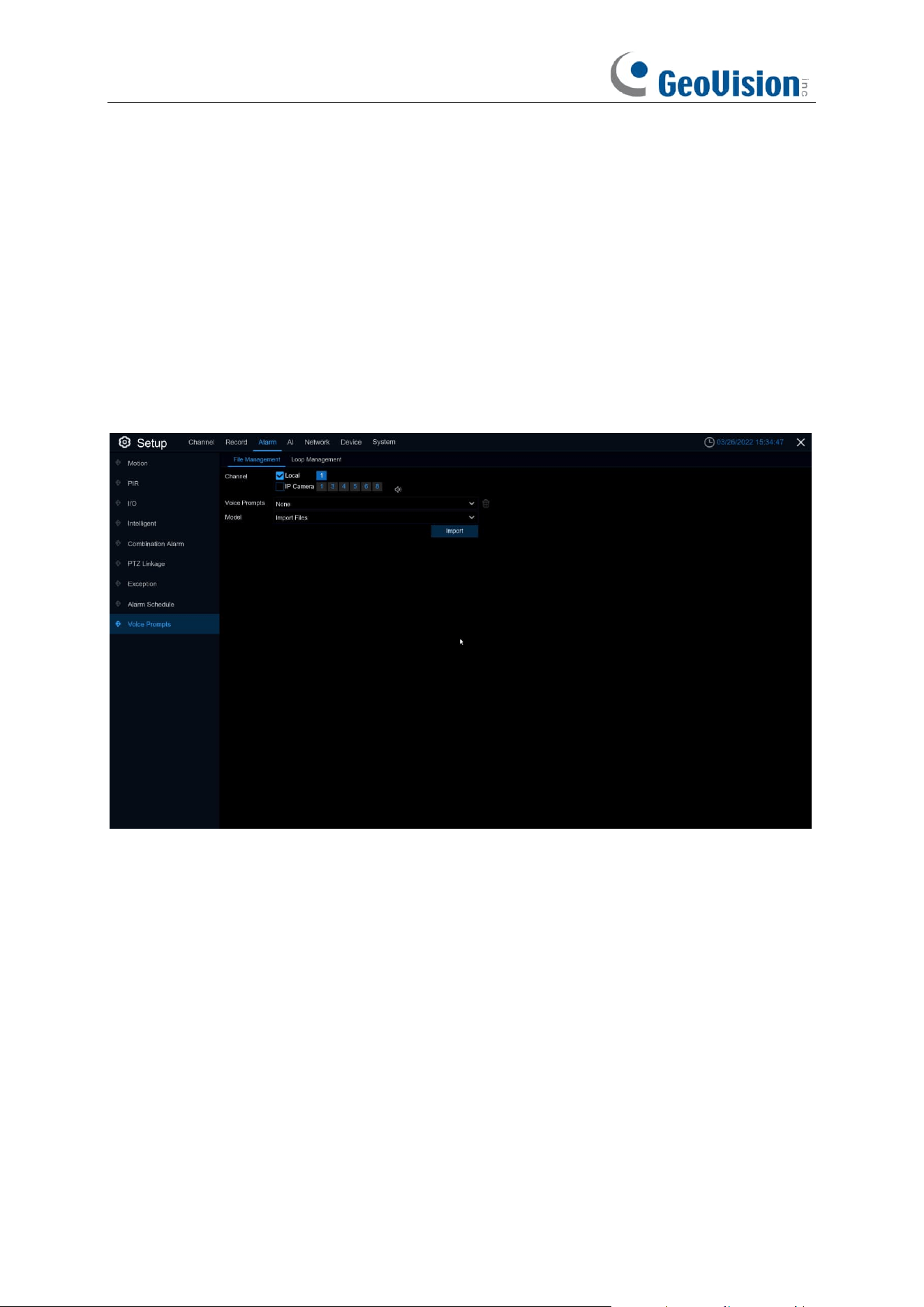
85
5.3.7 Voice Prompts
This function is to realize the alarm linkage when the alarm occurs. The system collects the alarm
signal and the voice broadcast equipment, and automatically or manually plays the associated
audio to the "intrusion" object on the scene.
5.3.7.1 File Management
GV-RNVR256G0-N
The system provides 3 different methods to create customized voices:
Import Files
,
Local
Conversion
and
Internet Server Conversion
Click
Import
to
import costumed audio using the following 3 methods:
Import File:
Local import (support the import of audio files in MP3, WMA, WAV format). Choose
Import Files
mode, and then click the
Import
button, and choose the audio file from your USB
memory. It is allowed to add only 1 file at a time. You can add multiple files at a time in the web
page.
Local Conversion:
Local translation (input of text content to be translated, translated to audio file,
and automatically saved to hard disk storage). Choose
Local Conversion
mode, and then input
the name of the file & plain text. Click
Import
button, the system will convert the text you input into
a voice file and save to the NVR storage.
Internet Server Conversion:
Web server translation (by locally entering the translated text
content, sent to the network server for translation into audio files, and automatically saved to the
local hard disk storage).
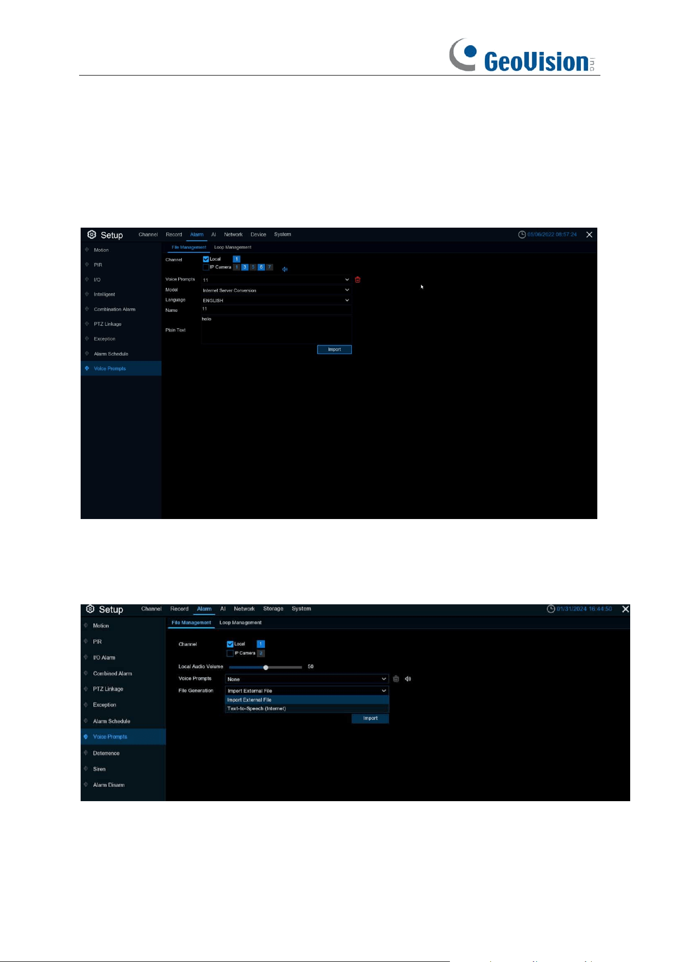
86
Internet Server Conversion
has multiple language options
. Local Conversion
language
selection is to English by default, and it doesn’t choose any other language for the user.
The input box has a maximum allowed input length of 1,024 bytes.
Import File
import audio files,
face database allow file size of 1~500K, non-face database allows file size of 1~5M.
After importing audio file, you can select which file to play in
Voice Prompt.
Only Local is supported for the broadcast mode.
Local: Local broadcast (when choosing this broadcast mode, the audio output shall is connected
to the device side)
GV-RNVRL810-P / GV-RNVR3240-N
Click
Import
to import broadcast audio, support two kinds of audio import methods, respectively,
Import External File, Text-to-Speech (Internet).
Import External File:
Local import (supports importing MP3, WMA, WAV format audio files).
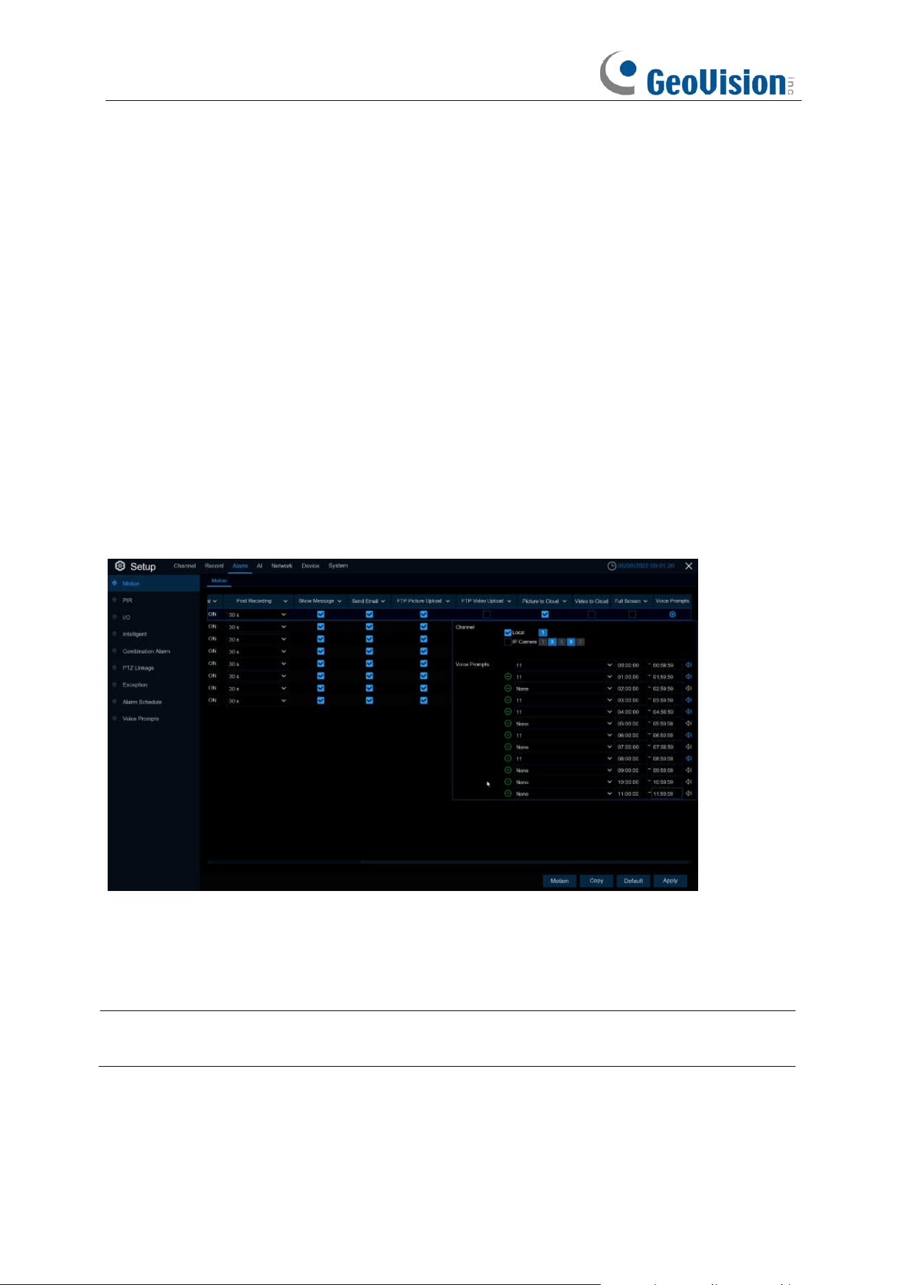
87
Text-to-Speech (Internet):
Web server translation (by locally inputting the text content to be
translated. Sent to the network server for translation into audio files. It is automatically saved to the
local hard disk for storage).
The maximum input length of the text input box is 200 bytes.
Import File:
Import audio file, the allowed file size for face and license plate library is 1~500K, and
the allowed file size for non-face and license plate library is 1~5M.
After importing audio, it can be selected in Voice Prompts.
Voice Prompts: Support 2 kinds of Prompts, respectively: Local and IPC channel.
Local Audio Volume:
you can adjust the volume output size of local broadcasting.
Local:
local broadcasting (when selecting this type of broadcasting, the device side needs to be
connected to the audio output device)
IP Camera:
IP Camera Broadcasting (to select this broadcasting method, the camera program
must have the voice broadcasting function, and at the same time, the camera side must support
audio output).
Voice Prompts setting by time period
An alarm type can support setting the voice broadcast of up to 12 time periods. There is no conflict
between the start and end time of any time period.
Voice broadcast setting based on face recognition: This function is to realize that when face
recognition occurs, the system collects the alarm signal and the voice broadcast equipment for
linkage, and automatically plays the associated audio to the scene "intrusion" object.
Note:
Imported audio based on black and white list face images can only be used for the
associated images.
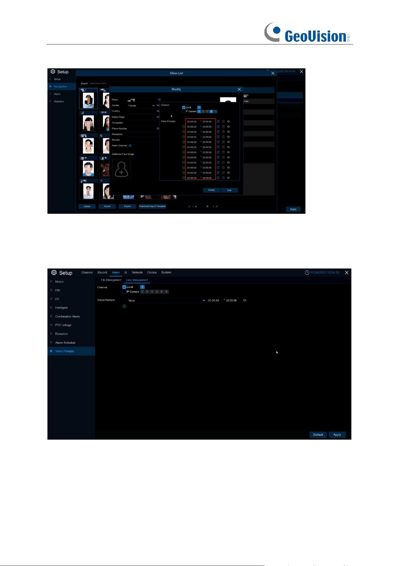
88
When the face detection events occur, there will be a voice prompt.
5.3.7.2 Loop Management
Voice Prompts selects the audio file, and after setting the time period, the selected audio file will
be played repeatedly without alarm or hearing the audio file, supporting the voice broadcast for up
to 12 time periods.
Local: Local broadcast (when choosing this broadcast mode, the audio output shall be connected
to the device side)
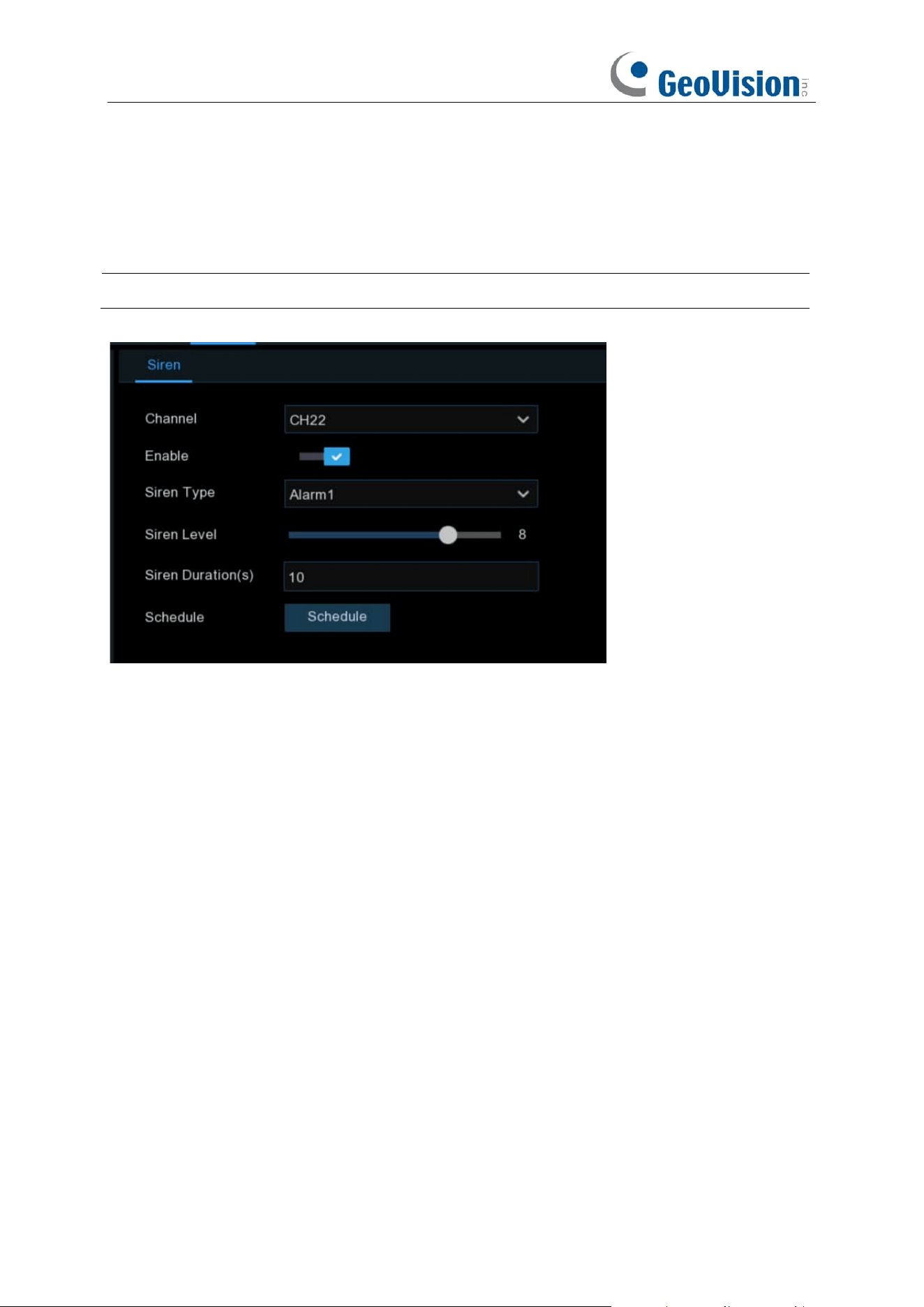
89
5.3.8 Siren
If the camera connected to the device has a built in speaker, you can set the siren related
parameters in this module.
Note: This function is only applicable when the NVR is connected to the GV-RFER12700.
Channel: Select the switch channel.
Enable: Used to set whether to enable the siren function.
Siren Type: Used to select the siren audio file. By default, two audio files are provided. You can
also import three customized audio files (of PCM format or WAV format). The audio sample rate of
the imported file cannot exceed 8000 Hz, and the file size cannot exceed 256 KB. After you select
a customized audio file to be imported, a Delete button appears on the right of the file, and you
can click the Delete button to delete the audio file. (Note: This function is supported by some IP
cameras only.)
File Name: If you select User-defined for Siren Type, you can enter the file name and click the
Import button on the right to import the customized audio file from a USB flash disk.
Siren Level: Used to set the siren volume level, which ranges from 1 to 10. The higher the level is,
the louder the volume is.
Siren Duration(s): Used to set the siren duration. You can adjust the value between 5 to 180
seconds.
Schedule: If the IP camera is connected to the NVR via the HTTP port, you can click the Schedule
button to open the setting page.
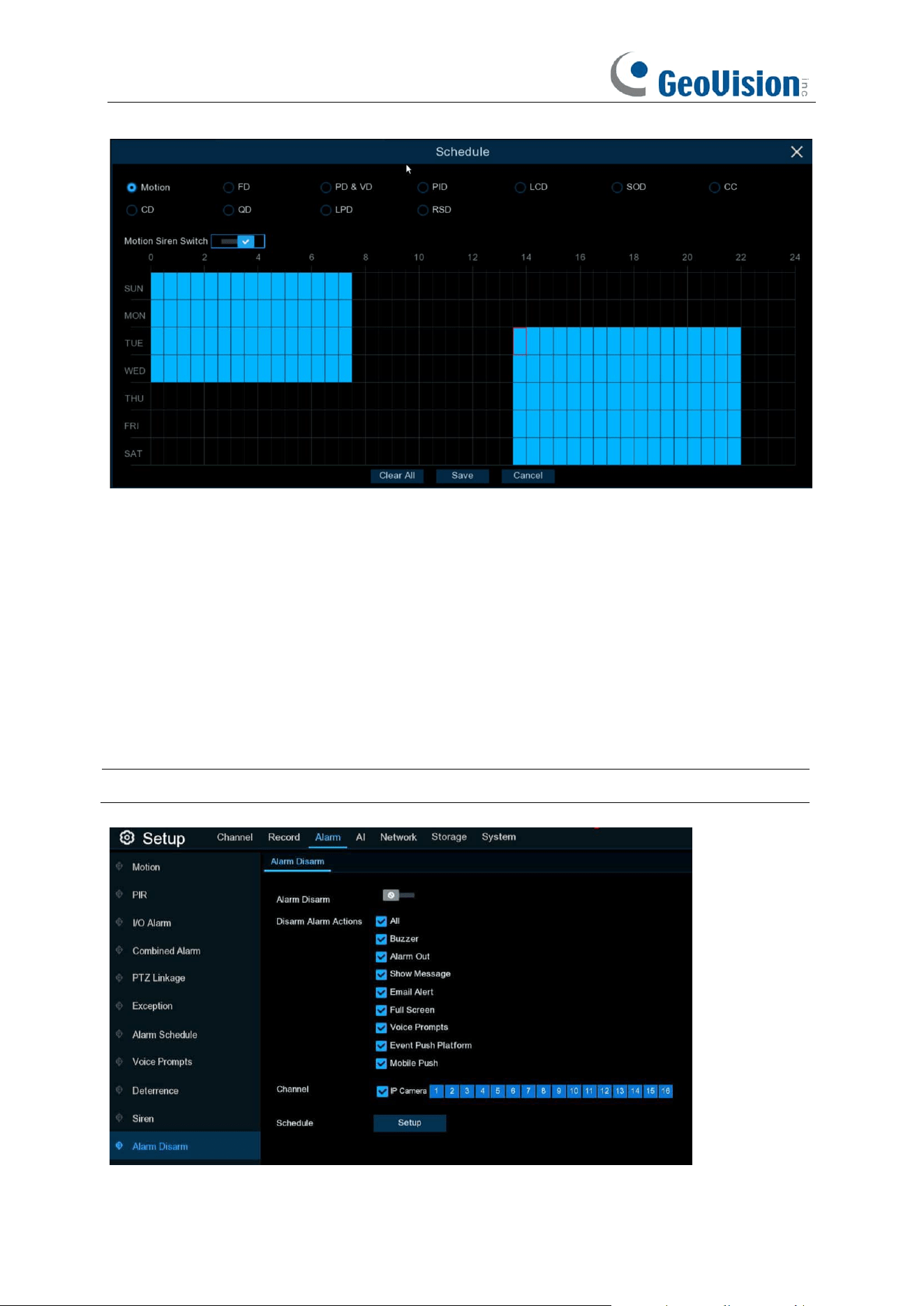
90
If a channel is selected in the schedule, it indicates that the channel can trigger siren alarms during
the corresponding period.
You can set the siren linkage alarm and effective time of a function by selecting the corresponding
function sub-tab and switch.
Clear All: Click this button to clear the selected status on all sub-tabs.
5.3.9 Disarming
After the one-click disarming function is enabled, you can cancel the response of the device to
various alarms. On this page you can set the relevant parameters including the disarming switch,
channel, type, and schedule.
Note: The Exception system alarms are not controlled by one-click disarming.
Disarming / Alarm Disarm: Used to set whether to enable the one-click disarming function.
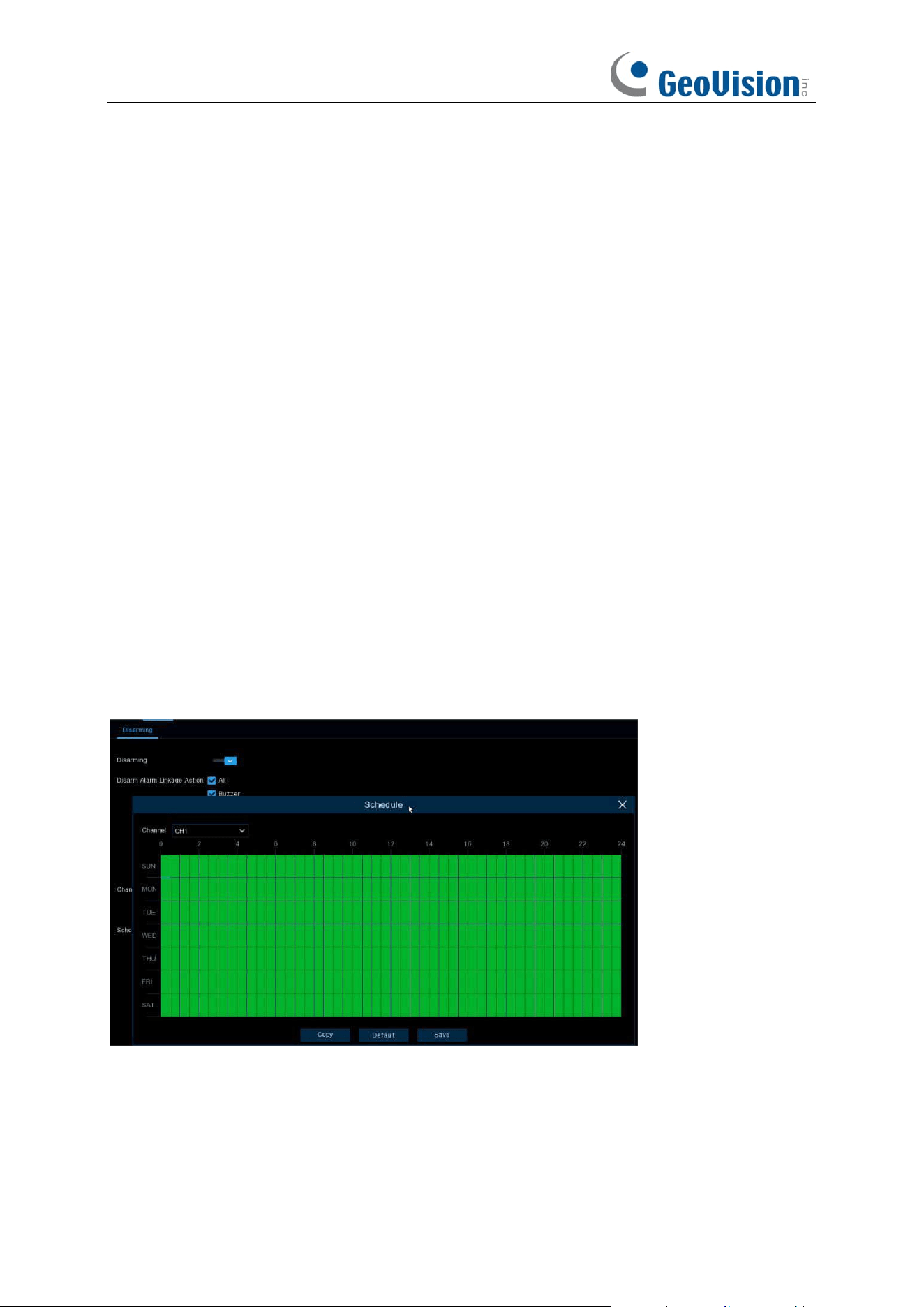
91
Disarm Alarm Linkage Action: Used to set the alarm linkage types to be disarmed.
All: Select or clear all the types.
Buzzer: Used to set whether to enable the buzzer. When the one-click disarming function is
enabled, you can select this option to disable the buzzer.
Alarm Out: Used to set whether to enable external alarm output. When the one-click disarming
function is enabled, you can select this option to disable the external alarm device when an alarm
is triggered.
Show Message: Used to set whether to display messages. When the one-click disarming function
is enabled, you can select this option to not display the alarm messages when motion is detected
on the preview page.
Send Email: Used to set whether to send emails. When the one-click disarming function is
enabled, you can select this option to make the NVR not automatically send an email when an
alarm is triggered.
Full Screen: Used to set whether to display in full screen. When the one-click disarming function
is enabled, you can select this option to make the channel configured with full-screen mode not
enter full screen mode on the preview screen when the channel triggers an alarm.
Event push Platform: When the alarm is triggered, the device does not push the alarm
information to the third-party platform.
Mobile Push: When one-key disarming is open, check Mobile Push, when alarm is triggered, the
device will not push the alarm information to the app.
Voice Prompts: Used to set whether to enable voice prompts. When the one-click disarming
function is enabled, you can select this option to disable voice prompts when a channel configured
with voice prompts triggers an alarm.
Channel: Select the channels to be disarmed.
Schedule: Click the Setup button to open the schedule setting page.
If a channel is selected in the schedule, it indicates that the channel is in disarming status within
the corresponding period.
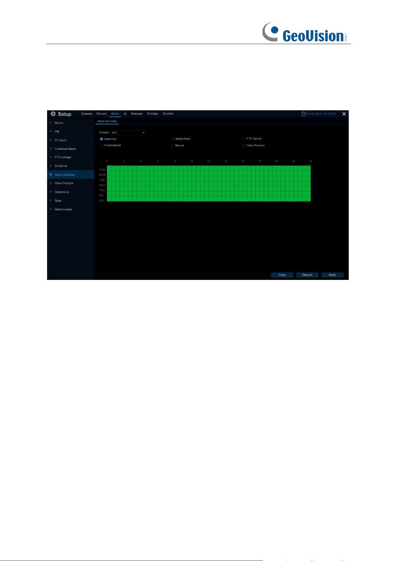
92
5.3.10 Alarm Schedule
In this menu, users can set the time period for external alarm output devices, push, FTP upload,
cloud upload, buzzer and other alarm response types to work through the schedules.
Channel: Select the channel and set its capture parameters.
When the time slot is marked in green, it means the channel is working for that time slot.

93
5.4 AI
The AI functions include
FD (Face Detection), PD & VD (Pedestrian and Vehicle Detection),
PID (Perimeter Intrusion Detection), LCD (Line Crossing Detection), CC (Cross Counting),
HM (Heat Map), CD (Crowd Density Detection), QD (Queue Length Detection),
and
RSD
(Rare Sound Detection)
.
Note:
1. The AI functions are only supported by the following AI-capable GV-R Series IP cameras.
Make sure to upgrade your camera to the latest firmware.
⚫ GV-RBL5800
⚫ GV-RBL5811
⚫ GV-REB5800
⚫ GV-RMS32810
2. To properly connect to the abovementioned IP cameras, make sure to the correct protocol
(
Private
). See 4.1.4 IP Camera for details.
3. The detection functions, including Face Detection, PD & VD, Perimeter Intrusion Detection,
Line Crossing Detection, Cross Counting, Crowd Density Detection, and Queue Length
Detection, might be mutually exclusive due to performance limitation. When the checkbox
of
Switch
is in grey color and unable to check, that means another AI function was enabled
in this camera already.
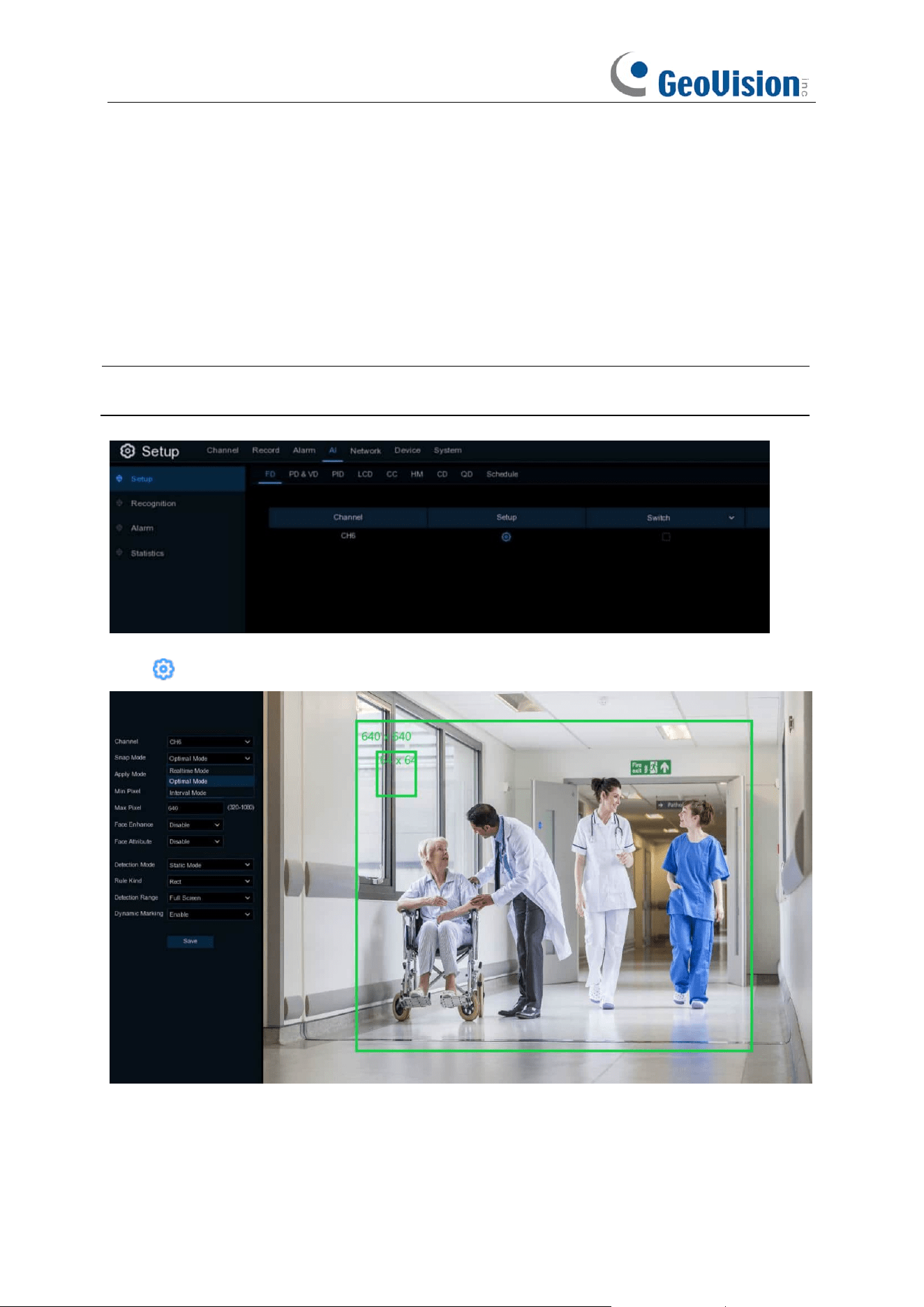
94
5.4.1 Setup
5.4.1.1 FD (Face Detection)
Face Detection function detects the faces of moving people appear in a pre-defined region, and a
series of actions can be taken when the alarm is triggered.
Note
: To enable the channel Face Detection function, you need to read and agree to the Face
Recognition Service Agreement.
Switch
: To enable or disable the face detection.
Click to configure the face detection conditions.
Channel: Channel selection

95
Snap / Capture Mode: There are “Optimal Mode” (automatically select & push the best image
from all face images of the same person whose faces were captured during his/her duration of
stay), “Realtime Mode” (push the first captured face image and push again the last captured face
image from the same person) and “Interval Mode” (customized the capture time and interval).
Apply Mode / Face Angle: Set the face detection angle, including “Frontal View”, “Multi Angle”
and “Customize / User-defined” mode.
If “Customize” mode is selected:
Roll Range: Set the range of face rotation under the customize mode.
Pitch Range: Set the range of face pitch under the customize mode
Yaw Range: Set the range of face horizontal flipping under the customize mode.
Picture Quality:
Set the picture quality.
Frontal View Default:
To load default values of front view.
Multi Angle Default:
To load default values of multi angle view.
Min Pixel: Set the minimum detection pixel box. The face can be recognized only when it is larger
than the pixel box.
Max Pixel: Set the maximum detection pixel box. The face can be recognized only when it is
smaller than the pixel box.
Face Enhance: Face enhancement makes it easier to recognize the moving faces, but it may
lower the whole picture quality.
Face Attribute: Enable this function to detect mask, glasses and facial expression.
Detection Mode: Motion Mode will detect moving faces. Static Mode will detect both moving faces
and still faces.
Rule Kind / Trigger Mode: Rect (rectangular) and Line (linear)
If you choose Rect mode, you can choose “Full Screen” or “Customize / User-defined” to adjust
the shape of rectangular detection zone in the camera image. Faces appear in this zone will be
detected and captured.
If you choose Line mode, you need to adjust the position, length of the line, and choose the
detection direction from B→ A or A→B.
Dynamic Marking / Bounding Box: If you enable this option, a capture box will be displayed
upon the face image in both live view images and recording files.
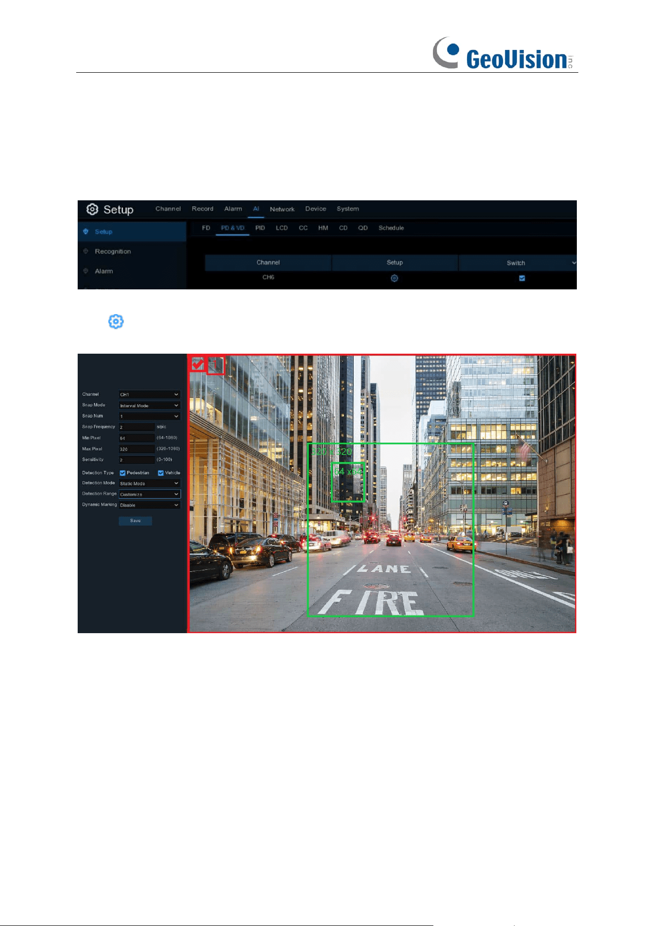
96
5.4.1.2 PD & VD (Pedestrian and Vehicle Detection)
Pedestrian and Vehicle Detection function detects the moving people / vehicles in a pre-defined
region, and a series of actions can be taken when the alarm is triggered.
Switch
: To enable or disable the Human & Vehicle detection.
Click to configure the detection conditions.
Channel: Channel selection
Snap Mode / Capture Mode: There are “Optimal Mode” (automatically select & push the best
image from all captured images of the same vehicle during its duration of stay), “Realtime Mode”
(push the first captured image and push again the last captured image from the same vehicle) and
“Interval Mode” (customized the capture time and interval).
Min Pixel: Set the minimum detection pixel box. The target objects can be recognized only when it
is larger than the pixel box.
Max Pixel: Set the maximum detection pixel box. The target objects can be recognized only when
it is smaller than the pixel box.
Sensitivity: Set the sensitivity level. Level 1 the lowest sensitivity level while level 100 is the
highest sensitivity level.
Detection Type: Choose the detection target objects.

97
Detection Mode: Motion Mode will detect moving objects. Static Mode will detect both moving
faces and still objects. Hybrid Mode means both static and moving targets are detected. Setting
the motion mode can reduce false alarms.
Detection Range: Set the detection zone. You can choose “Full Screen” or “Customize” to
adjust the shape of rectangular detection zone in the camera image. Target objects appear in this
zone will be detected and captured.
Dynamic Marking / Bounding Box: If you enable this option, a capture box will be displayed
upon the detected objects in both live view images and recording files.
PTZ Auto Tracking: If your PTZ camera is connected, you might see this function. Enable to
activate the PTZ auto tracking function. View more on 5.1.4.1.2.1 Controlling PTZ.
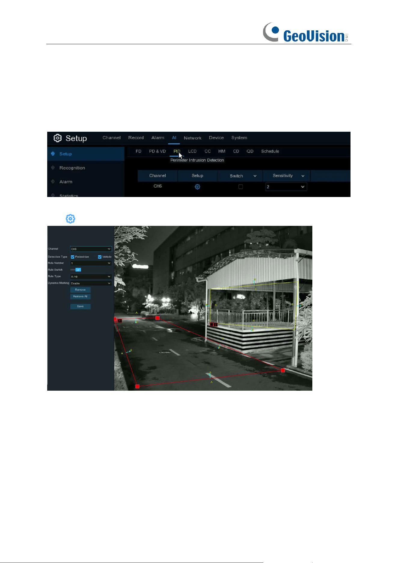
98
5.4.1.3 PID (Perimeter Intrusion Detection)
Perimeter
Intrusion Detection function detects people, vehicle or other objects which enter and
loiter in a pre-defined virtual region, and some certain actions can be taken when the alarm is
triggered.
Switch
: To enable or disable the Perimeter Intrusion Detection.
Click to configure the detection conditions.
Channel: Channel selection
Detection Type: Choose the detection target objects.
Rule Number
: Max. 4 rules available.
Rule Switch:
Activate or inactivate the rule.
Rule Type:
Detection direction from B→ A, A→B or A→B
Dynamic Marking / Bounding Box: If you enable this option, the border of the detection zone will
be displayed in both live view images and recording files.
1. Choose one of the
Rule Number
. It is the number of LCD lines. Maximum 4 lines you can
draw.
2. Choose the detection target type.
3. To enable the detection in
Rule Switch
.
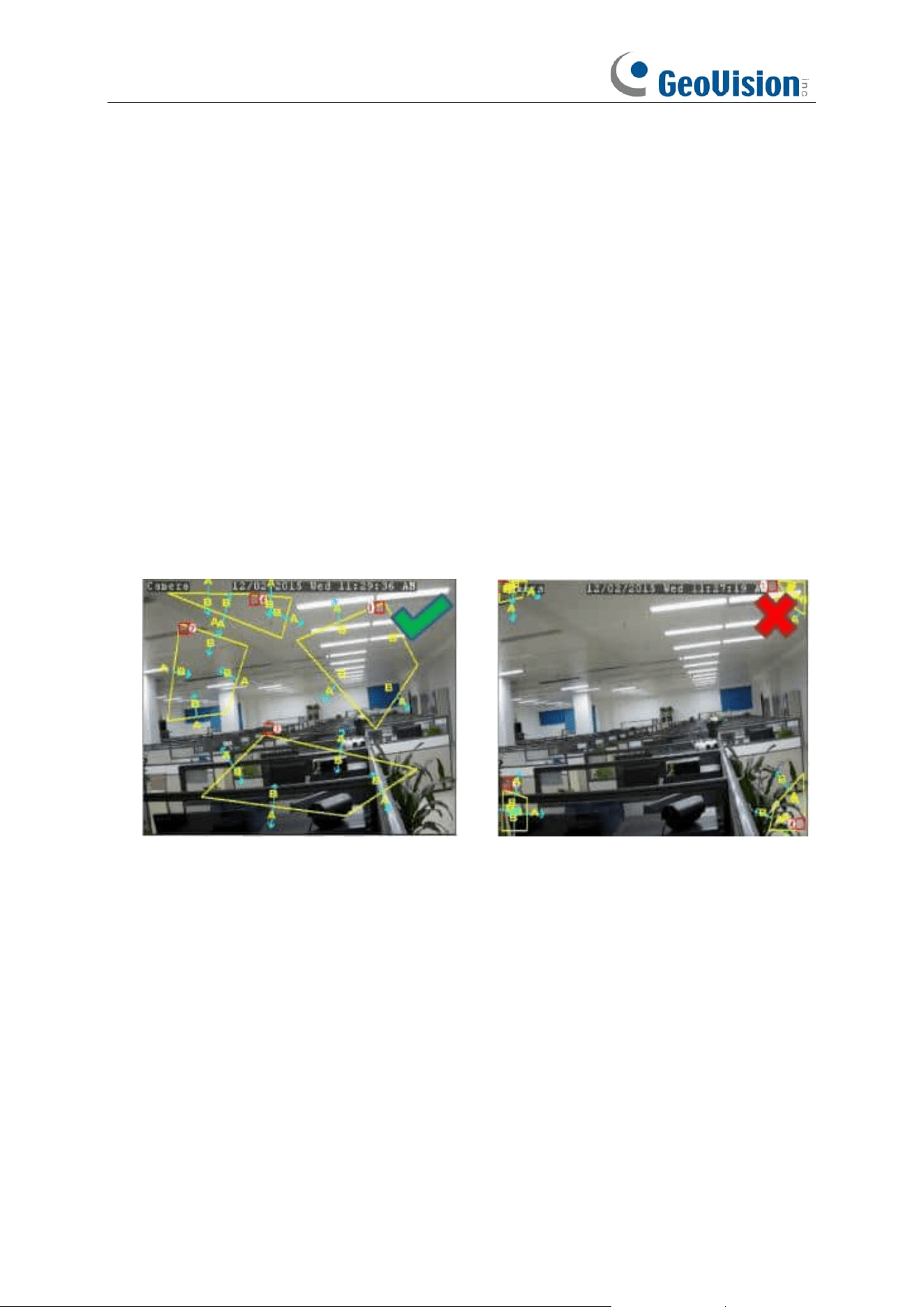
99
4. Choose a
Rule Type
.
A→B: NVR will only detect the objects move from side A to side B;
B→A: NVR will only detect the objects move from side B to side A;
A→B: NVR will detect the objects move from either side B to side A or side A to side B.
5. Use your mouse to click 4 points in the camera picture to draw a virtual region. The sharp of
the region should be a convex polygon. Concave polygon will be not able to save.
6. Click
Save
to save your settings.
7. If you want to modify the position or sharp of region, click the red box in the region, the borders
of the region will be changed to red color. Click and hold the left button of your mouse to move
the position of the region, or drag the corners to resize the region.
8. If you want to remove one of the regions from the camera picture, click the red box in the
region and then click
Remove
button. Click
Remove All
will delete all regions.
Notice:
1) The perimeter shall not be too close to the edges/corners of the camera picture, since it may
fail to trigger the detection when the target pass through the edges/corners.
2) The shape of the regions shall not be too narrow/small, since it may fail to trigger the detection
when the target passes through outside the perimeter.
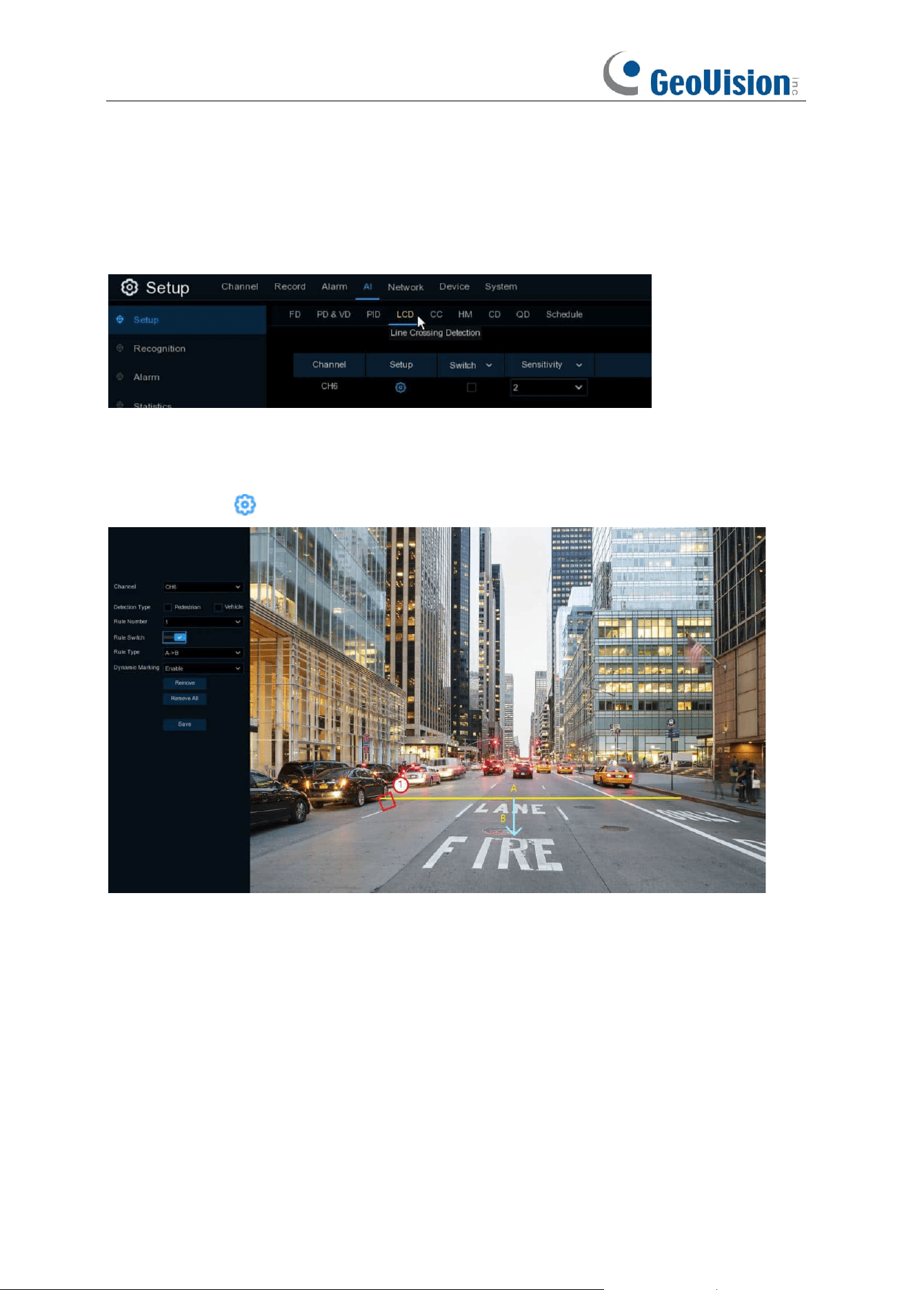
100
5.4.1.4 LCD (Line Crossing Detection)
Line Crossing Detection function detects people, vehicle or other objects which cross a
pre-defined virtual line, and some certain actions can be taken when the alarm is triggered.
Switch:
Check the box to enable the LCD function.
Sensitivity
: The sensitivity setting for triggering area intrusion detection, the higher the sensitivity
setting, the easier it is to trigger the alarm.
Click
Setup
icon to configure the detection conditions.
Channel
: Select the channel you want to configure
Target Validity: Used to adjust the detection validity of the target. The higher the validity, the more
closely the target matches the set criteria, for example, a motor vehicle. However, higher validity
levels also increase the risk of false negatives, while lower validity values may lead to false
positives. The range is from 1 to 4, with lower values indicating higher confidence levels.
Min Pixel: Set the minimum detection pixel box. The target objects can be recognized only when it
is larger than the pixel box.
Max Pixel: Set the maximum detection pixel box. The target objects can be recognized only when
it is smaller than the pixel box.
Detection Type: Choose the detection target objects.
Rule Number
: Max. 4 rules available.
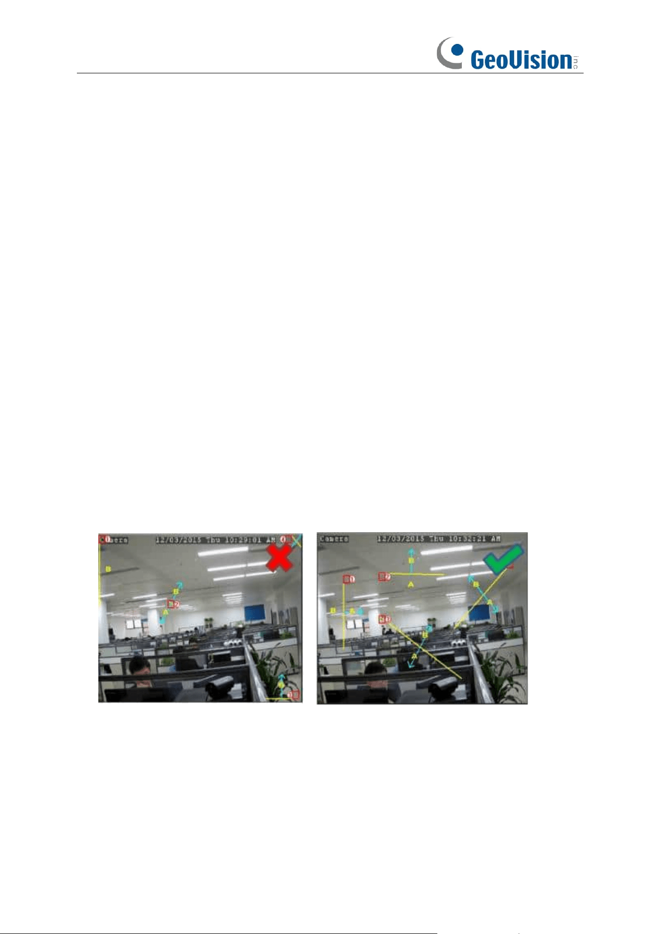
101
Rule Switch:
Activate or inactivate the rule
Dynamic Marking / Bounding Box: If you enable this option, the border of the detection zone will
be displayed in both live view images and recording files.
1. Choose one of the
Rule Number
. It is the number of LCD lines. Maximum 4 lines you can
draw.
2. Choose the detection target type.
3. To enable the detection in
Rule Switch
.
4. Choose a
Rule Type
.
A→B: NVR will only detect the action from side A to side B;
B→A: NVR will only detect the action from side B to side A;
A→B: NVR will detect the action from either side B to side A or side A to side B.
5. Use your mouse to click 2 points in the camera picture to draw a virtual line.
6. Click
Save
to save your settings.
7. If you want to modify the position or length of the line, click the red box in the line, the color of
the line will be changed to red color. Click and hold the left button of your mouse to move the
line, or drag the terminals to modify the length or position of the line.
8. If you want to remove one of the lines from the camera picture, click the red box in the line and
then click
Remove
button. Click
Remove All
will delete all lines.
Notice:
1) The lines shall not be too close to the edges of the camera picture, to avoid any failure to trigger
an alarm when the target cross through it.
2) The lines shall not be set too short, to avoid any failure to trigger an alarm when the target
passes outside it.

102
5.4.1.5 CC (Cross-Counting)
Cross-Counting function counts the times for moving objects or people across the virtual lines.
Switch:
Check the box to enable the function.
Sensitivity
: Set the sensitivity level. Level 1 the lowest sensitivity level while level 4 is the highest
sensitivity level.
Click
Setup
icon to configure the detection conditions.
Channel
: Select the channel you want to configure
Type: Choose the detection target objects. Motion will detect all moving objects, Person will
detect human beings only, Vehicle will detect vehicles only.
Alarm Number
: The NVR will send an alert if the number of entries minus the number of exits
exceeds the alarm number. E.g., the number of entries is 601 while the number of exits is 400, and
the alarm number you set is 200, 601-400 > 200, then the NVR will send an alert.
Start Time
: Set the detection start time.
End Time
: Set the detection end time.
Reset Count
: Clear the counting number.
Rule Number
: Only 1 rule available.
Rule Switch:
Activate or inactivate the rule.
1. Choose the detection target type.
2. Set the
Alarm Number
,
Start Time
and
End Time
.
3. To enable the detection in
Rule Switch
.
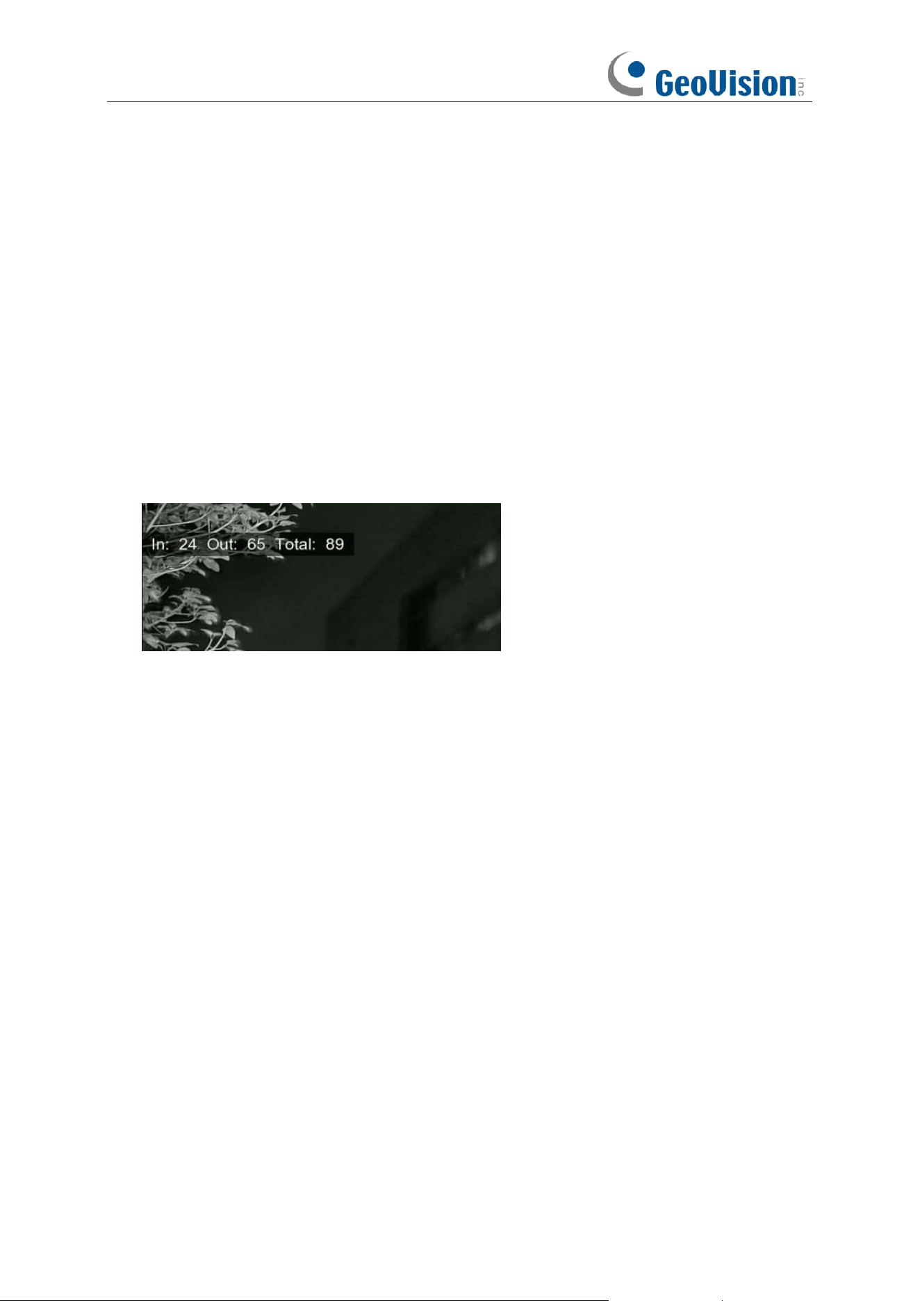
103
4. Choose a
Rule Type
.
A
→
B:
If a target object is detected moving from side A to side B, the system will count 1 to
enter number; if a target object is detected moving from side B to side A, the system will count
1 to exit number.
B
→
A:
If a target object is detected moving from side B to side A, the system will count 1 to
enter number; if a target object is detected moving from side A to side B, the system will count
1 to exit number.
5. Use your mouse to click 2 points in the camera picture to draw a virtual line.
6. Click
Save
to save your settings.
7. If you want to modify the position or length of the line, click the red box in the line, the color of
the line will be changed to red color. Click and hold the left button of your mouse to move the
line, or drag the terminals to modify the length or position of the line.
8. If you want to remove one of the lines from the camera picture, click the red box in the line and
then click
Remove
button. Click
Remove All
will delete all lines.
9. The statistical data of cross counting will be displayed on the left top corner of the image.
10. If you want to clear the statistical data of cross counting, click the
Reset Count
button.
11. If you want the green tracking frame that surrounds a detected object to be invisible during live
view mode and playback, then choose Disable in the
Dynamic Marking / Bounding Box.
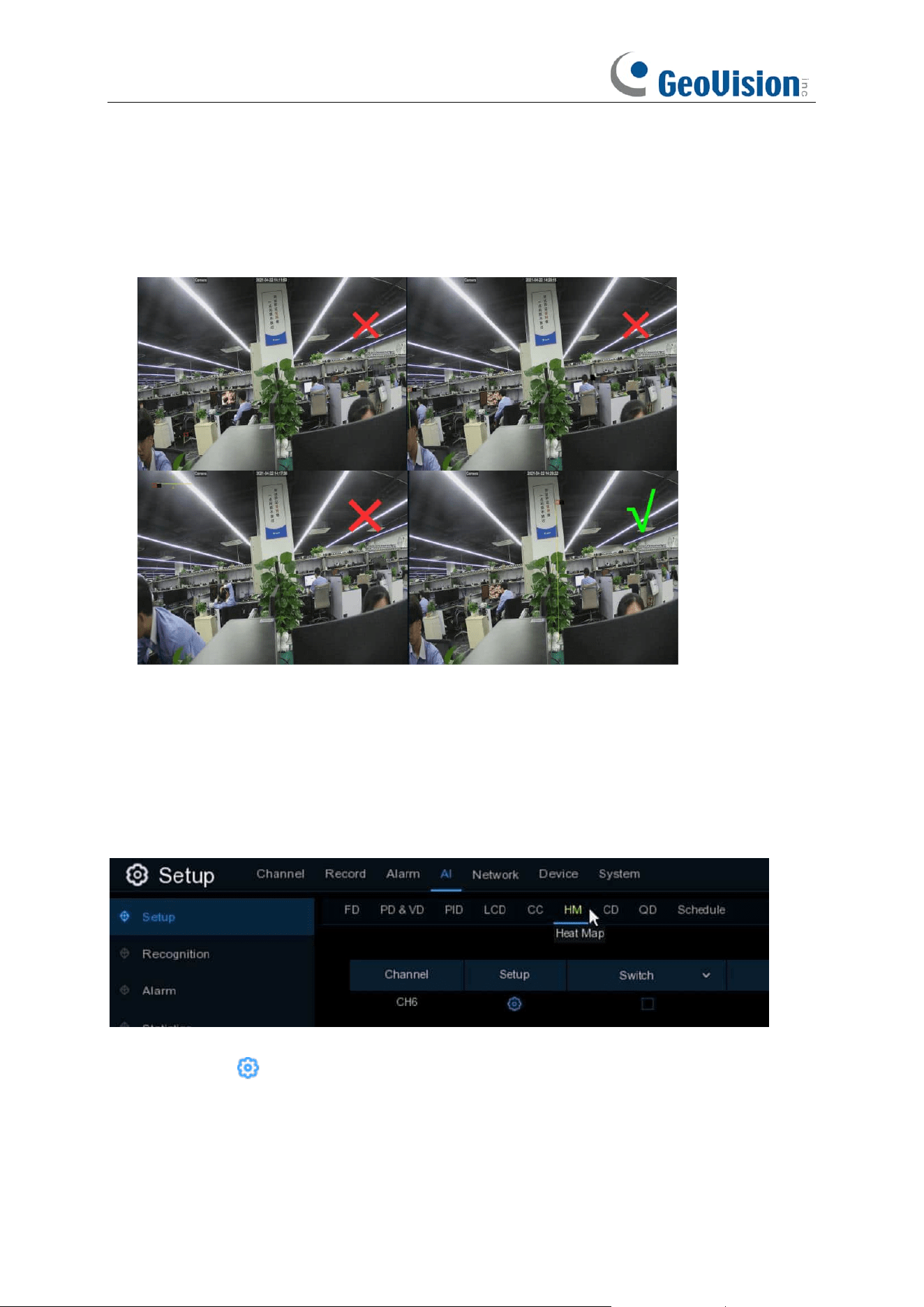
104
Notice:
1) The lines shall not be too close to the edges of the camera picture, to avoid any failure to
trigger an alarm when the target cross through it.
2) The lines should be in the area that detected object can be reach.
3) The lines shall not be set too short, to avoid any failure to trigger an alarm when the target
passes outside it.
5.4.1.6 HM (Heat Map)
Automatically regular detect and count the movement of objects in the monitoring area. The
frequency of people flows will be identified by different colors.
Switch:
Check the box to enable LCD function.
Click
Setup
icon to configure the detection conditions.
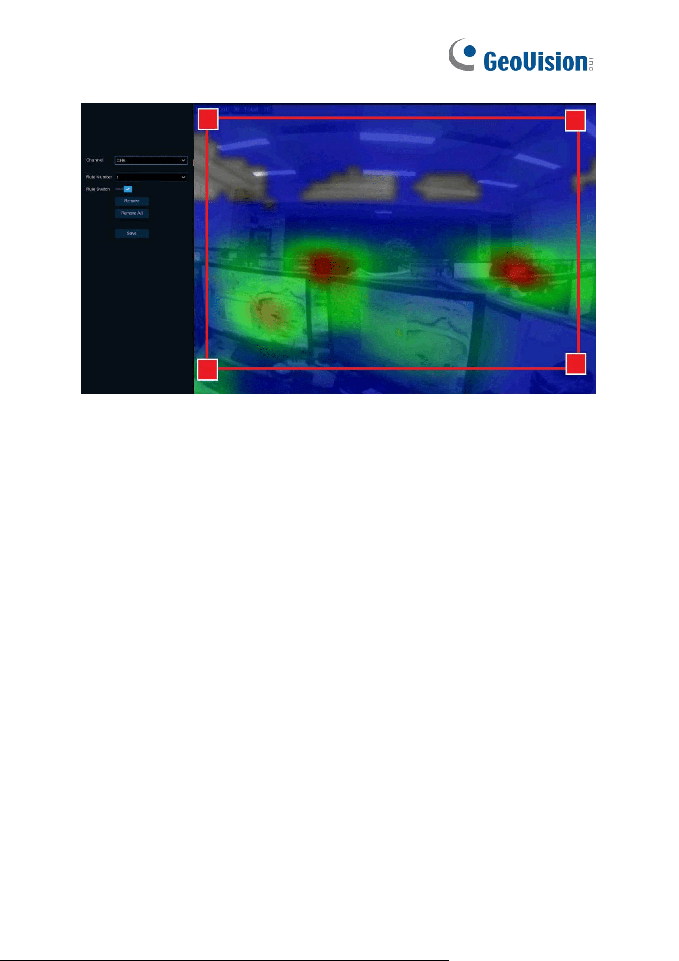
105
1. To enable the detection in
Rule Switch
.
2. Use your mouse to click 4 points in the camera picture to draw a virtual region. The sharp of
the region should be a convex polygon. Concave polygon will be not able to save.
3. Click
Save
to save your settings.
4. If you want to modify the position or sharp of region, click the red box in the region, the borders
of the region will be changed to red color. Click and hold the left button of your mouse to move
the position of the region, or drag the corners to resize the region.
5. If you want to remove one of the regions from the camera picture, click the red box in the
region and then click
Remove
button. Click
Remove All
will delete all regions.
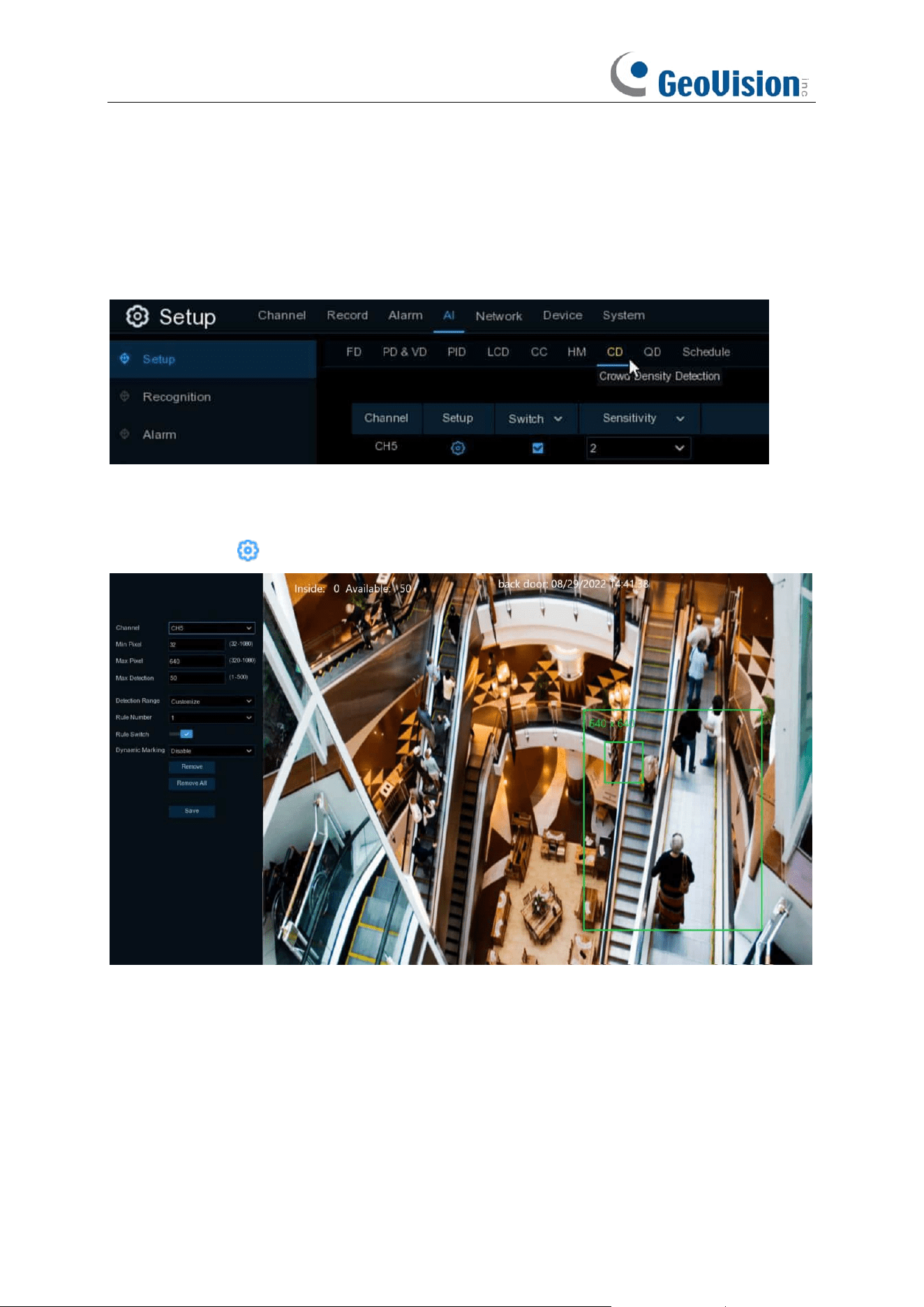
106
5.4.1.7 CD (Crowd Density Detection)
Crowd density detection is used to detect crowd gathering to maintain a controllable order in
certain area.
Switch:
Check the box to enable the CD function.
Sensitivity
: Set the sensitivity level. Level 1 the lowest sensitivity level while level 4 is the highest
sensitivity level.
Click
Setup
icon to configure the detection conditions.
Min Pixel: Set the minimum detection pixel box. The people can be recognized only when he/she
is larger than the pixel box.
Max Pixel: Set the maximum detection pixel box. The people can be recognized only when he/she
is smaller than the pixel box.
Max Detection / Capacity:
The NVR will send an alert if the number of people inside the detection
area exceeds the Max Detection number.
Dynamic Marking / Bounding Box: If you enable this option, the border of the detection zone will
be displayed in both live view images and recording files.
1. Set the min. pixel and max. pixel.

107
2. Set the limitation number in
Max. Detection / Capacity
.
3. To enable the detection in
Rule Switch
.
4. Set the
Detection Range
to be full screen or customize.
5. If you choose customized detection range, you will need to use your mouse to click 8 points in
the camera picture to draw a virtual region.
6. Click
Save
to save your settings.
7. If you want to modify the position or sharp of region, click the red box in the region, the borders
of the region will be changed to red color. Click and hold the left button of your mouse to move
the position of the region, or drag the corners to resize the region.
8. If you want to remove one of the regions from the camera picture, click the red box in the
region and then click
Remove
button. Click
Remove All
will delete all regions.
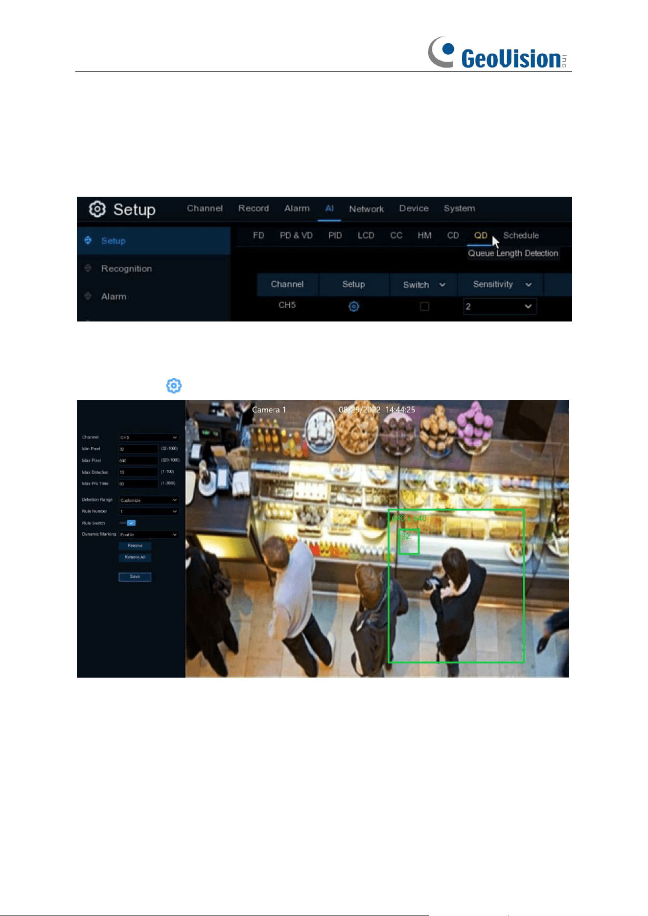
108
5.4.1.8 QD (Queue Length Detection)
Queue length detection is used to detect the status of a queue, including its length and
stagnation time.
Switch:
Check the box to enable the QD function.
Sensitivity
: Set the sensitivity level. Level 1 the lowest sensitivity level while level 4 is the highest
sensitivity level.
Click
Setup
icon to configure the detection conditions.
Min Pixel: Set the minimum detection pixel box. The people can be recognized only when he/she
is larger than the pixel box.
Max Pixel: Set the maximum detection pixel box. The people can be recognized only when he/she
is smaller than the pixel box.
Max Detection / Capacity:
The NVR will send an alert if the number of crowds in the line inside
the detection area exceeds the Max Detection number.
Max. Pro Time / Max. Staying Time:
The NVR will send an alert if the stagnation time of the
queue is longer than the given processing time.

109
Dynamic Marking / Bounding Box: If you enable this option, the border of the detection zone will
be displayed in both live view images and recording files.
1. Set the min. pixel and max. pixel.
2. Set the limitation number in
Max. Detection
.
3. Set the limitation number in
Max. Pro Time
, the unit is second.
4. To enable the detection in
Rule Switch
.
5. Set the
Detection Range
to be full screen or customize.
6. If you choose customized detection range, you will need to use your mouse to click 8 points in
the camera picture to draw a virtual region.
7. Click
Save
to save your settings.
8. If you want to modify the position or sharp of region, click the red box in the region, the borders
of the region will be changed to red color. Click and hold the left button of your mouse to move
the position of the region, or drag the corners to resize the region.
9. If you want to remove one of the regions from the camera picture, click the red box in the
region and then click
Remove
button. Click
Remove All
will delete all regions.
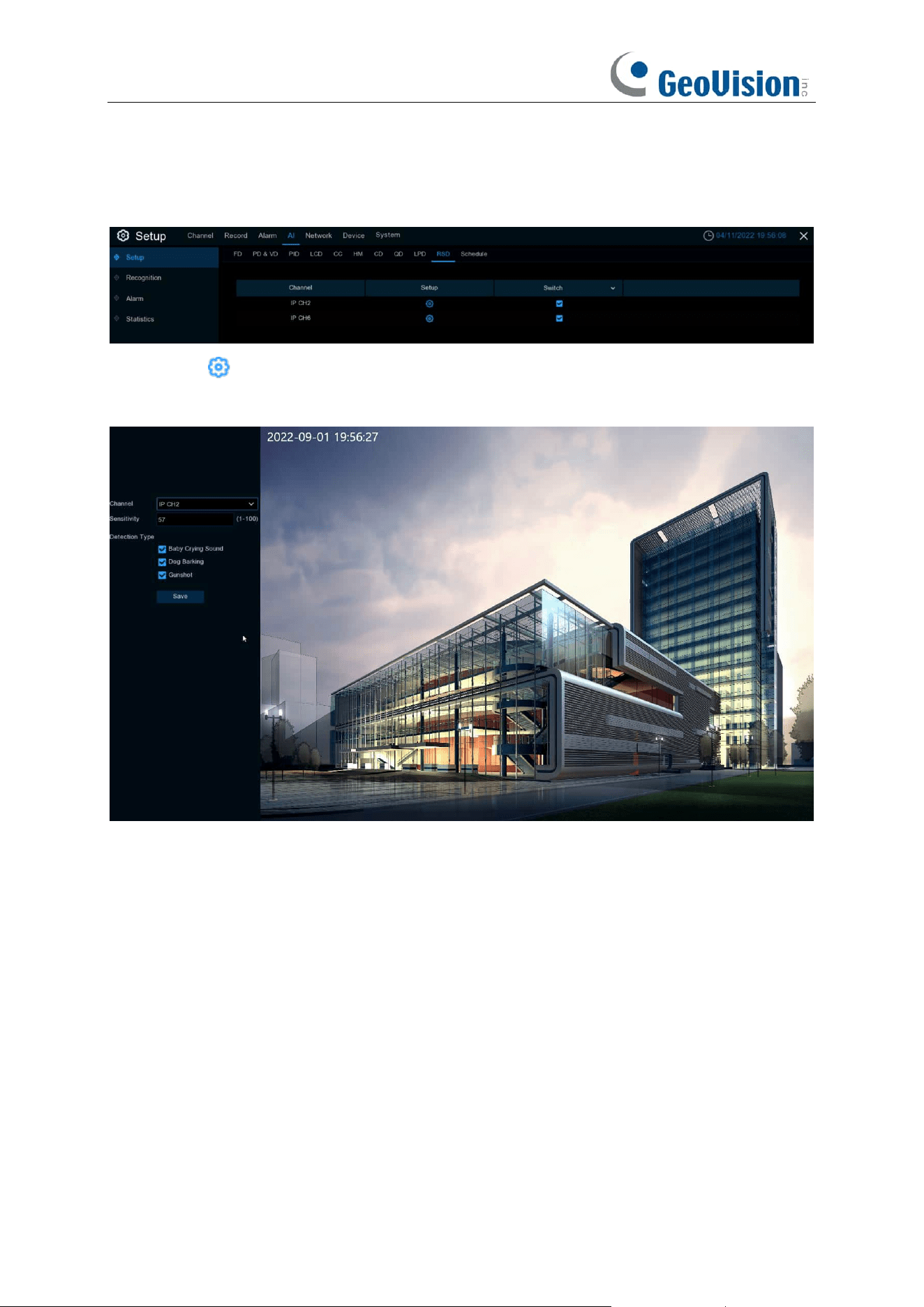
110
5.4.1.9 RSD (Rare Sound Detection)
Setup: Click to enter setup page.
Switch: Enable or disable RSD function.
Channel: Channel selection.
Sensitivity: Sensitivity, 1 is the minimum,100 in the maximum.
Detection Type: Choose the detection type by clicking to enable detection for Baby Crying
Sound, Dog Barking, or Gunshot.
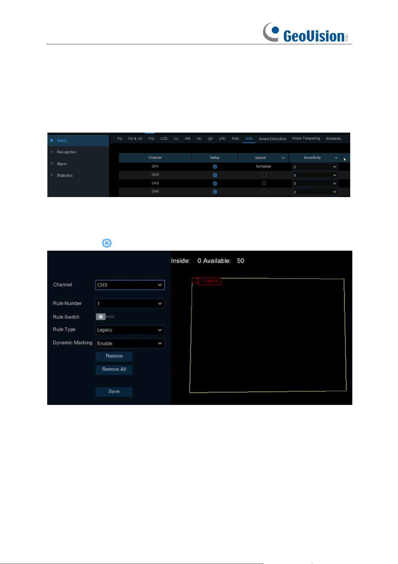
111
5.4.1.10 SOD (Stationary Object Detection)
Stationary Object Detection function detects the objects left over or lost in the pre-defined region
such as the baggage, purse, dangerous materials, etc., and a series of actions can be taken when
the alarm is triggered.
Switch:
Check the box to enable SOD function.
Sensitivity
: Set the sensitivity level. Level 1 the lowest sensitivity level while level 4 is the highest
sensitivity level.
Click
Setup
icon to draw a virtual region in the camera image.
Channel
: Select the channel you want to configure
Rule Number
: Max. 4 rules available.
Rule Switch:
Activate or inactivate the rule
1. Choose one of the
Rule Number
. It is the number of SOD area. Maximum 4 areas you can set
for SOD function.
2. To enable the detection in
Rule Switch
.
3. Choose a
Rule Type
.
Legacy: NVR will only detect the left-over objects;
Lost: NVR will only detect the lost objects;
Lost & Legacy: NVR will detect both left-over & lost objects.
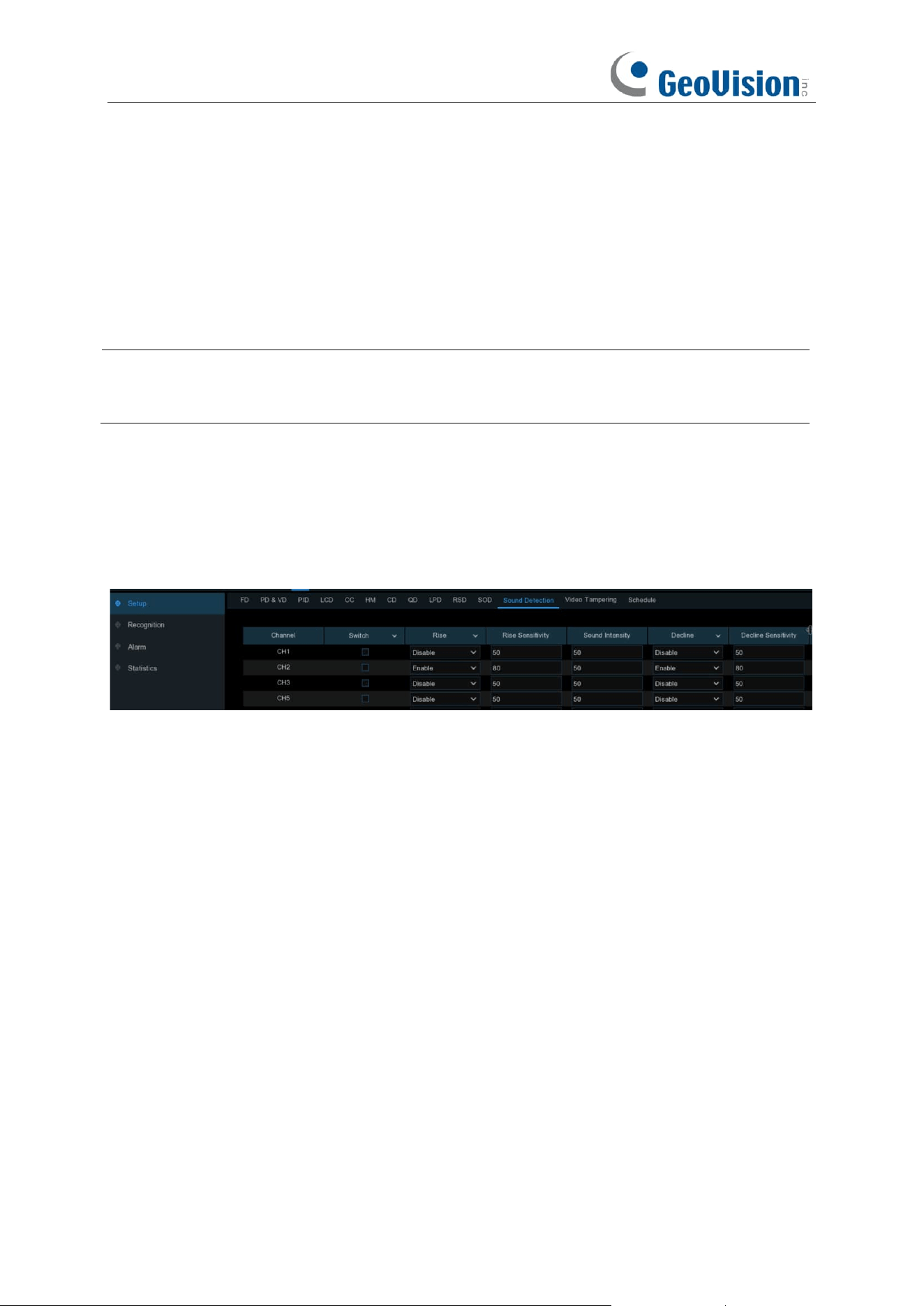
112
4. Use your mouse to click 4 points in the camera picture to draw a virtual region. The shape of
the region should be a convex polygon. Concave polygon is not applicable.
5. Click
Save
to save your settings.
6. If you want to adjust the size of the region, click the red box in the region, the borders of the
region will be changed to red color. Long press the left button of your mouse to move the
whole region, or drag the corners to resize the region.
7. If you want to remove one of the regions from the camera picture, click the red box in the
region and then click
Remove
button. Click
Remove All
will delete all regions.
Note:
1. The detection area shall be greater than or equal to the size of the detected object.
2. The detected object cannot be covered.
5.4.1.11 Sound Detection
With the sound detection, it can trigger an alarm while detecting the sound rise or decline, and
some certain actions can be taken when the alarm is triggered.
Switch: Enable or disable sound detection.
Rise: Enable or disable sound rise detection.
Rise Sensitivity: Set the sensitivity level. Level 1 the lowest sensitivity level while level 100 is the
highest sensitivity level.
Sound / Volume Intensity: Set a threshold of sound intensity, the lower value, the more
sensitivity.
Decline: Enable or disable sound Decline detection.
Decline Sensitivity: Set the sensitivity level. Level 1 the lowest sensitivity level while level 100 is
the highest sensitivity level.
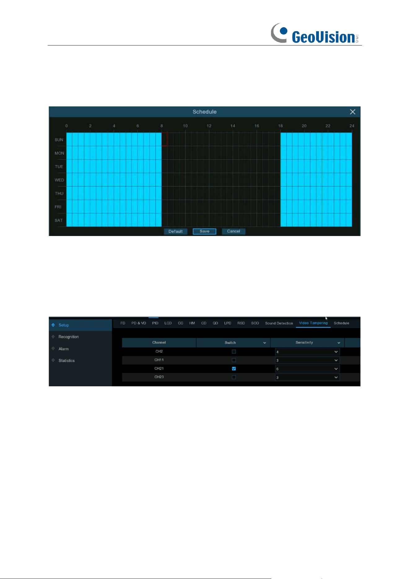
113
Schedule: Each square represents 30 minutes. Using the mouse, click on a particular square to
change or click and drag the mouse over the squares corresponding to your desired period. The
sound detection will be activated if the time table is in blue color, oppositely the detection will be
inactivated if the time table is in black color.
5.4.1.12 Video Tampering
Video Tampering detects the occlusion of camera images, and some certain actions can be taken
when the alarm is triggered.
Switch: Enable or disable the function
Sensitivity: The sensitivity level is from 1 to 6, with a default value of 3. Higher sensitivity will be
easier to trigger the detection.
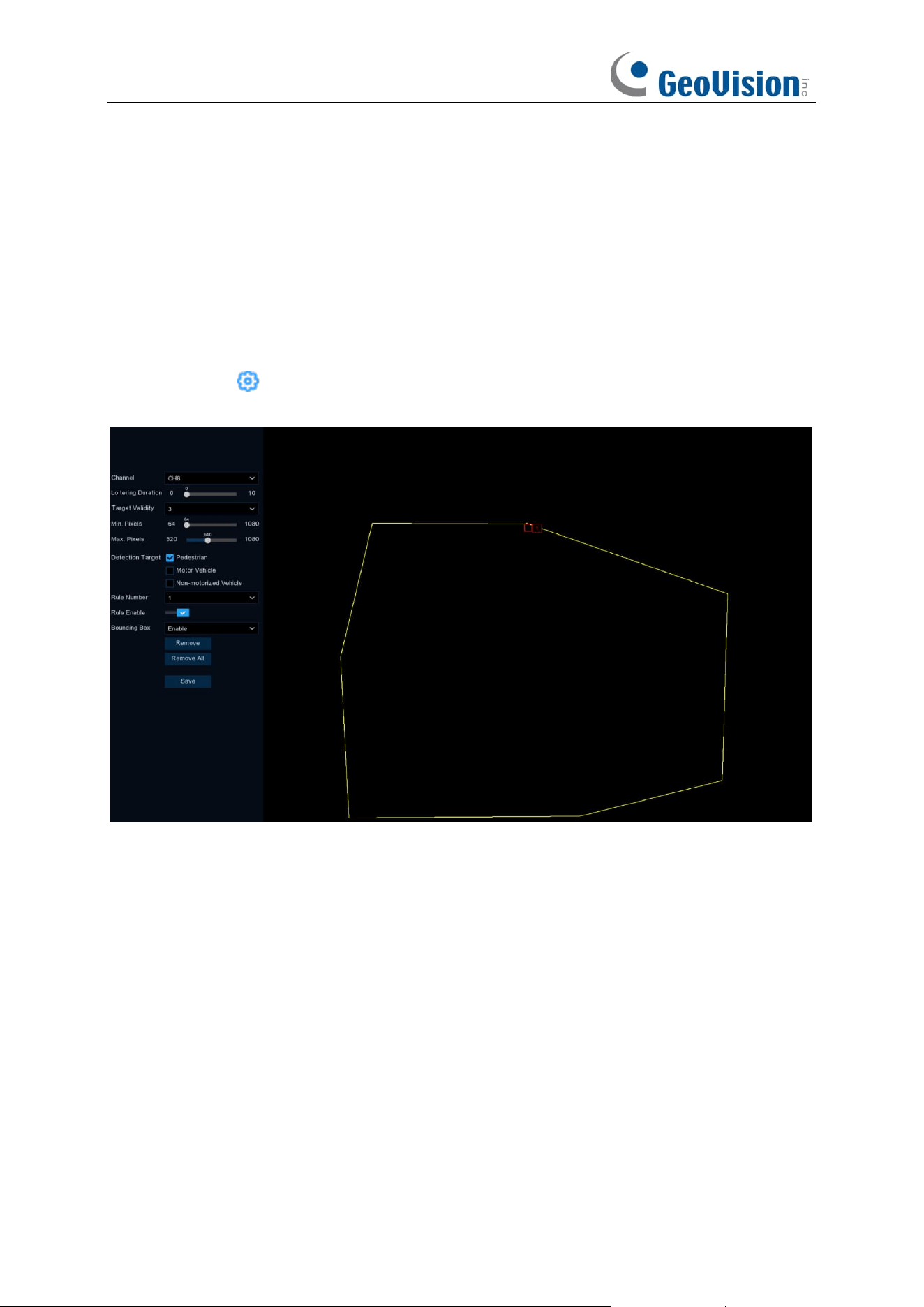
114
5.4.1.13 Intrusion
Intrusion detection detects whether there is an object in the video to invade the set restricted area.
Linkage alarm according to the judgment result.
Switch:
Check the box to enable the Intrusion function.
Sensitivity
: The sensitivity setting for triggering area intrusion detection, the higher the sensitivity
setting, the easier it is to trigger the alarm.
Click
Setup
icon to configure the detection conditions.
Channel
: Select the channel you want to configure.
Time Threshold: Indicates that the target enters the alert area and stays there for the duration of
the time before generating an alarm. For example, if it is set to 5, the alarm will be triggered
immediately after the target invades the area for 5s, and the maximum duration can be set to 10s.
Target Validity: The similarity between the detection target and the set detection type. The alarm
is triggered only when the set similarity level is reached or exceeded. The higher the setting level
the higher the similarity requirement, the more obvious the desired target characteristics and the
higher the alarm accuracy. Levels can be set from 1 to 4.1 represents a similarity of 80% or more,2
represents a similarity of 60% or more,3 represents a similarity of 40% or more,4 represents a
similarity of 20% or more.
Min. Pixel: Sets the min recognized pixel. The target has to be larger than the set pixel to be
recognized.
Max. Pixel: Sets the max recognized pixel. The target has to be smaller than the set pixels to be
recognized.
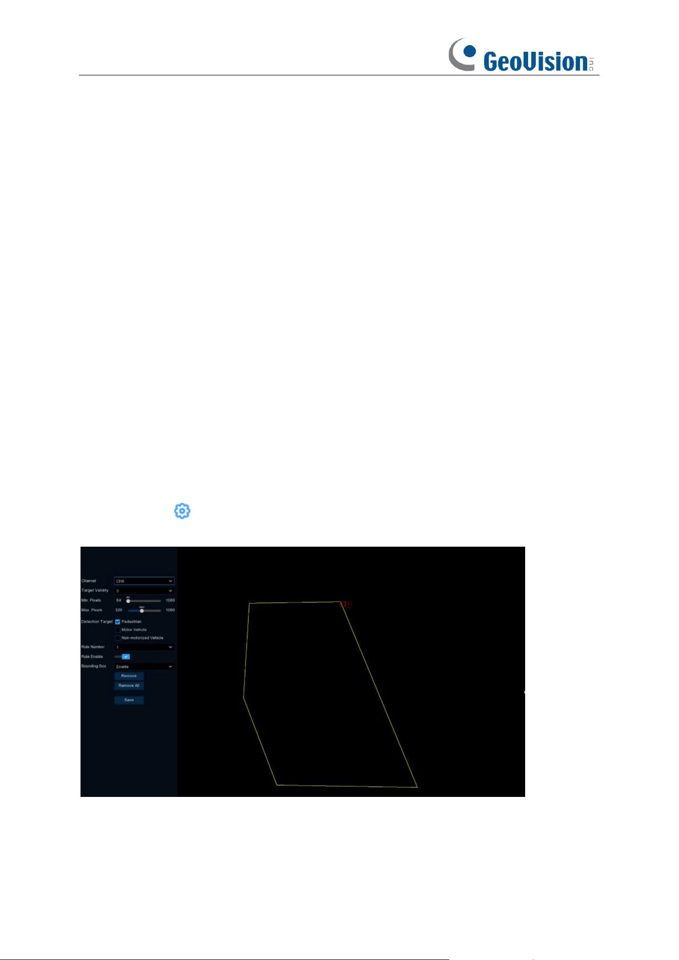
115
Detection Target: Setting the detection type;
Pedestrian: Only intruding pedestrians are detected;
Motorized: Only intruding motorized vehicles are detected;
Non-Motorized: Only intruding non-motorized vehicles are detected;
Don't Select Any Type: All moving targets are detected.
Rule Number: Select the rule number, click the left mouse button in the right preview screen to
draw the detection area connected with the first and last endpoints, and then click Save to
complete the area drawing. When you need to clear the warning area, click "Remove" to delete the
selected area; click "Remove All" to delete all areas.
Rule Enable: Enable detection in Rule Switch.
Bounding Box: When on, the target detection box is displayed in the live screen.
5.4.1.14 Region Entrance / Exiting
The Region Entrance / Exiting detection function can detect whether an object enters / leaves the
set warning area and link the alarm according to the judgment result. The specific setting steps are
shown below.
Switch:
Check the box to enable the Intrusion function.
Sensitivity
: The sensitivity setting for triggering area intrusion detection, the higher the sensitivity
setting, the easier it is to trigger the alarm.
Click
Setup
icon to configure the detection conditions.
Channel
: Select the channel you want to configure.
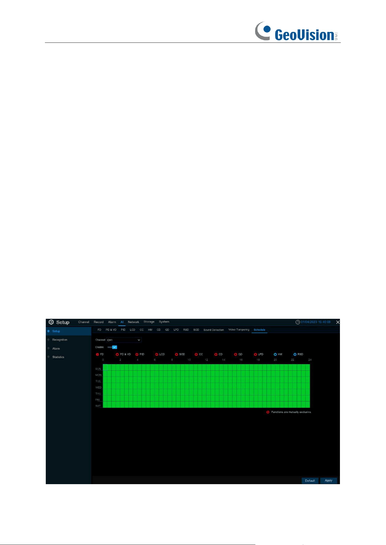
116
Target Validity: The similarity between the detection target and the set detection type. The alarm
is triggered only when the set similarity level is reached or exceeded. The higher the setting level
the higher the similarity requirement, the more obvious the desired target characteristics and the
higher the alarm accuracy. Levels can be set from 1 to 4.1 represents a similarity of 80% or more,2
represents a similarity of 60% or more,3 represents a similarity of 40% or more,4 represents a
similarity of 20% or more.
Min. Pixel: Sets the min recognized pixel. The target has to be larger than the set pixel to be
recognized.
Max. Pixel: Sets the max recognized pixel. The target has to be smaller than the set pixels to be
recognized.
Detection Target: Setting the detection type;
Pedestrian: Only Enter Region pedestrians are detected;
Motorized: Only Enter Region motorized vehicles are detected;
Non-Motorized: Only Enter Region non-motorized vehicles are detected;
Don't Select Any Type: All moving targets are detected.
Rule Number: Select the rule number, click the left mouse button in the right preview screen to
draw the detection area connected with the first and last endpoints, and then click Save to
complete the area drawing. When you need to clear the warning area, click "Remove" to delete the
selected area; click "Remove All" to delete all areas.
Rule Enable: Enable detection in Rule Switch.
Bounding Box: When on, the target detection box is displayed in the live screen.
5.4.1.15 Schedule

117
In order to active the AI function, you need to config the schedule. The schedule will be active in
24 hours x 7 days.
To set the schedule, choose one channel then click on one of the detection items on the right side,
then drag the cursor to mark the slots. The schedule is valid only for the selected channel each
time when you set. If you want to use the same schedule for other channels, use Copy function.
Click Save to save your settings.
Functions are mutually exclusive: Functions that are mutually exclusive with the selected
function.
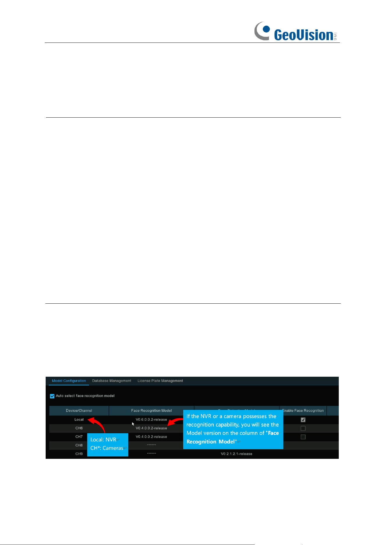
118
5.4.2 Face Recognition
To start face recognition, you need to configure the face recognition algorithm model and
database.
Note:
1.
For
GV-RNVR256G0-N
, the function is only applicable when connected to the following R
Series AI-capable GV-IP cameras. Make sure
Face Detection
is enabled on the cameras.
⚫ GV-RBL5800
⚫ GV-RBL5811
⚫ GV-REB5800
⚫ GV-RMS32810
2.
For
GV-RNVRL810-P / GV-RNVR3240-N,
the function is only applicable when connected to
the following R Series AI-capable GV-IP cameras. Makre sure
Face Recognition
is
enabled on the cameras.
⚫ GV-RBL5800
⚫ GV-RBL5811
⚫ GV-REB5800
⚫ GV-RMS32810
3.
To see AI applications for different scenarios using Face Recognition results, see 7.1.9.5
Face Attendance, 7.1.9.1 Face Search, and 7.1.9.4 Repeat Visitors.
5.4.2.1 Model Configuration
To choose the face algorithm model. Auto select recognition model is recommended. Face
Recognition is enabled by default.
The face AI algorithm mainly includes two parts: Detection and Recognition.
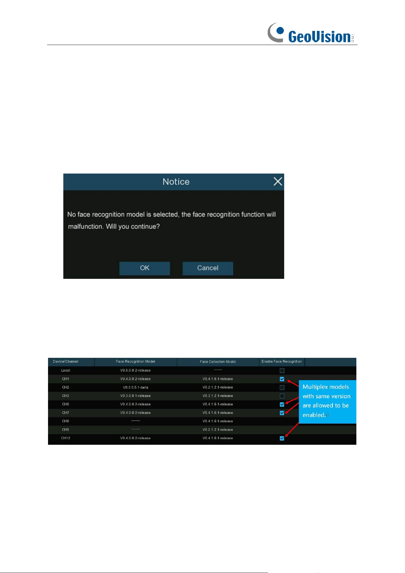
119
➔ Recognition is mostly used to extract, analyze and compare the face features. Recognition
capability is possessed by the NVR and some of IP cameras.
To fully implement the face detection and recognition function, the system will select a face
recognition model automatically when you use the face AI function at the first time.
If you want to choose the model by manual, untick the checkbox of "Auto select recognition
model", and then tick the checkbox of the model you want to enable.
Rules & advices for manual selection:
1. At least one face recognition algorithm model must be enabled, otherwise the face recognition
function would malfunction.
2. Between NVR and camera, you can only select either-or.
3. Models with across versions are disallowed to be selected.
4. Newer version (with bigger digital sequence) is preferred to be selected due to its algorithm
optimization and database update.
5. Multiplex models with same version are allowed & recommended to be enabled. This would
help to decrease the analysis loading on a single NVR or camera and accelerate the
recognition.
If one or more selected cameras (not all) are off-line, the recognition mission will be automatically
assigned to the rest of selected camera(s).
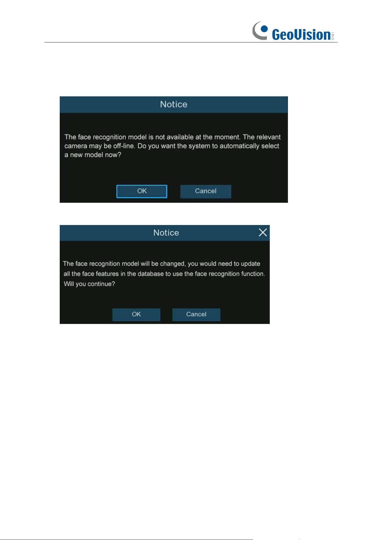
120
6. When the Model is enabled on a single camera and if the camera is off-line, the face
recognition will stop working. System will send an alert notification shown as below. Click
"
OK
" to let the system automatically select a new model. If you click "
Cancel
", you would
need to configure the recognition model by manual later.
7. If you want to change the model to a different version, the system would send you a notice,
click "
OK
" to continue.
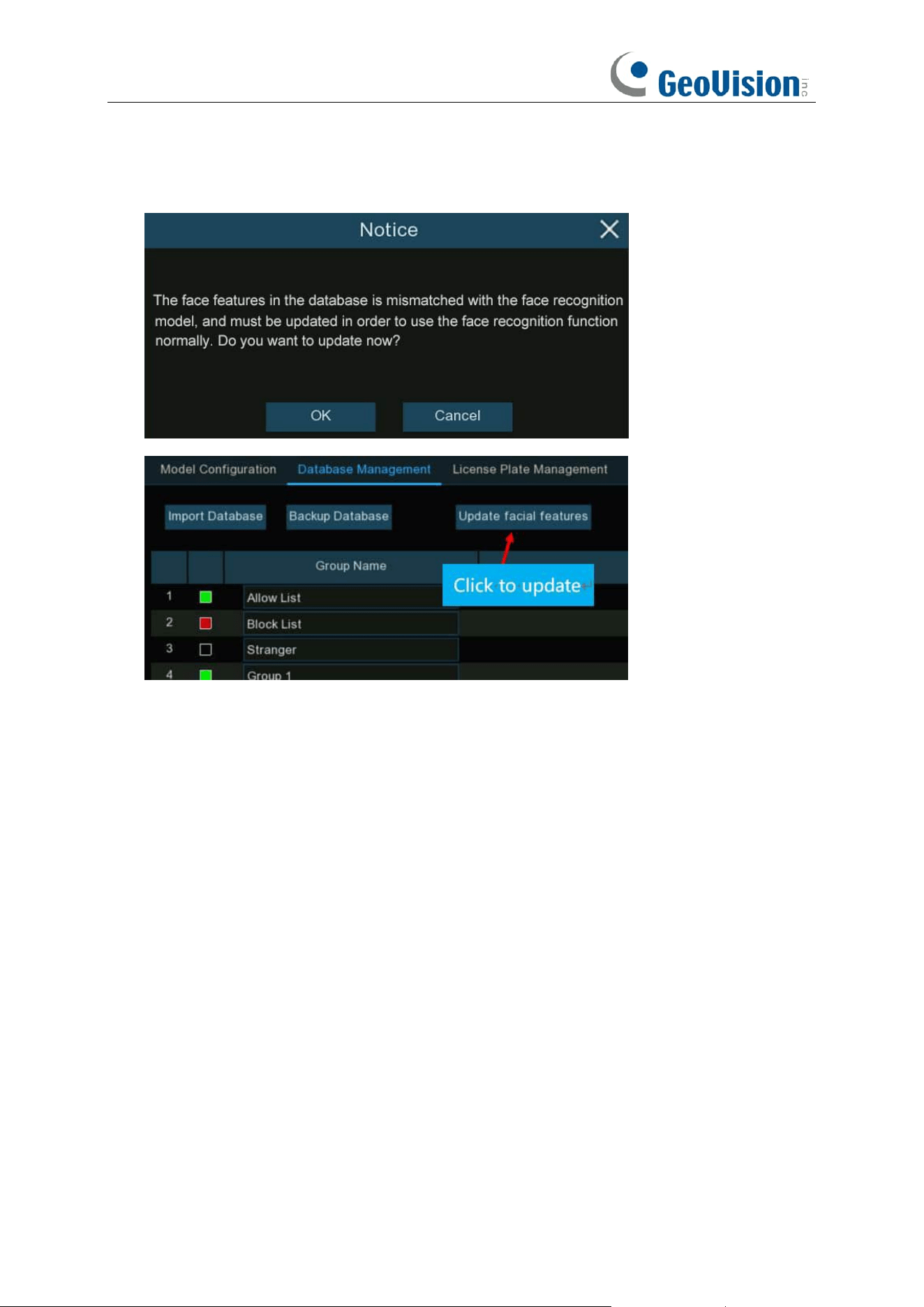
121
8. If the recognition model has been changed to a different version, the system would send you
a notice, click "
OK
" to continue. If you click "
Cancel
", you would need to go to "
Database
Management
" menu and then click "
Update facial features
" button to update the database.
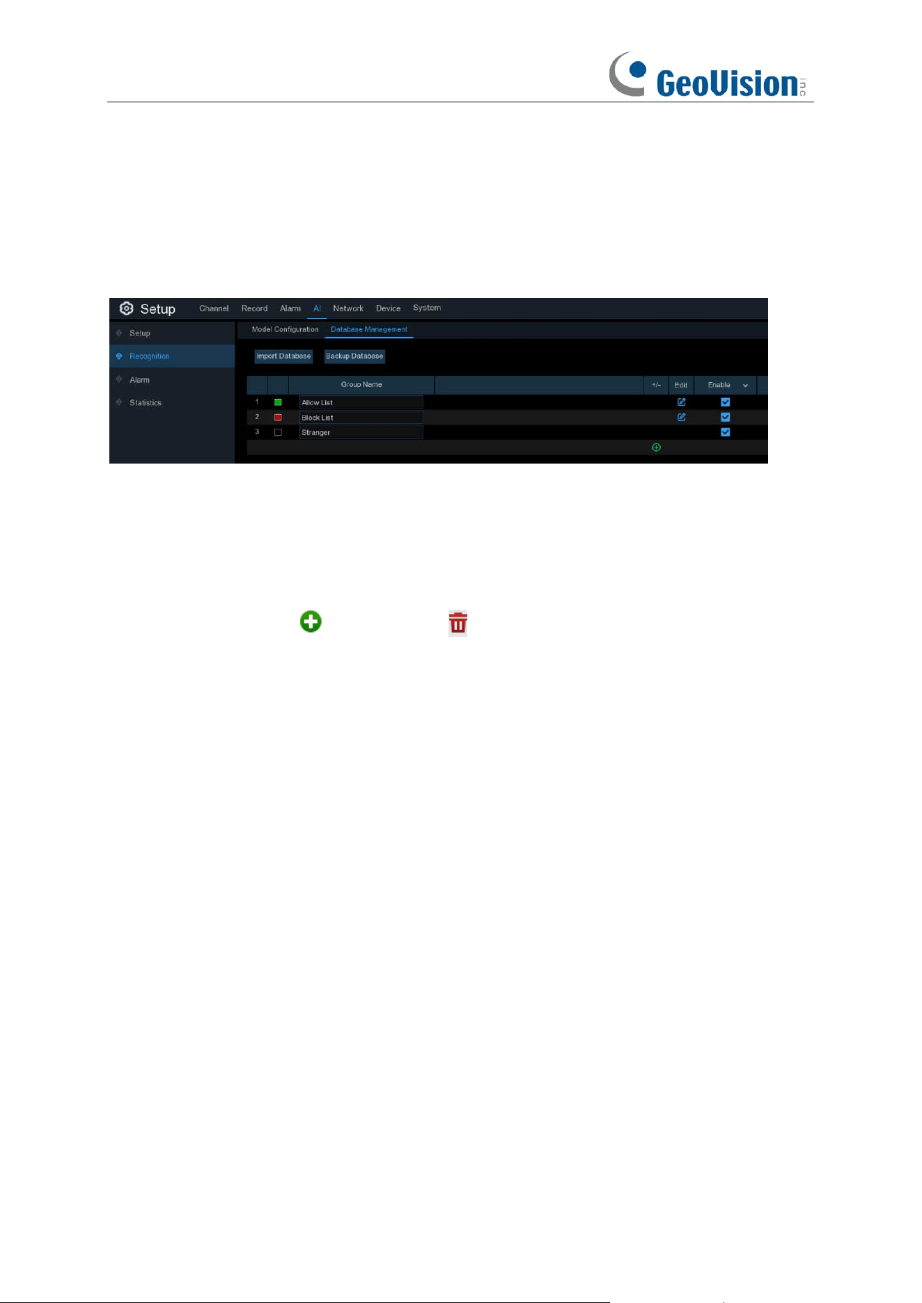
122
5.4.2.2 Database Management
You're able to create and manage the face profiles (database) to classify different people into
different groups in order to quickly identify people in remote and realize intelligent alarm
beforehand.
There are 3 default groups: Allow List, Block List, and Stranger:
➔
Allow List:
Mostly used to define a list of people that are regarded as acceptable or
trustworthy, such as family members, colleagues, frequent customers, etc.
➔
Block List:
Mostly used to define a list of people that are regarded as unacceptable or
untrustworthy and should be excluded or avoided.
➔
Stranger:
All ungrouped people will be identified as stranger.
You can use the add icon and delete icon to add or delete customized groups.
Import Database: Import database from USB memory / local HDD storage. Note that this will
overwrite the existing settings and face profiles.
Backup Database: Export database to USB memory / local HDD storage.
Enable: Check to enable the group.
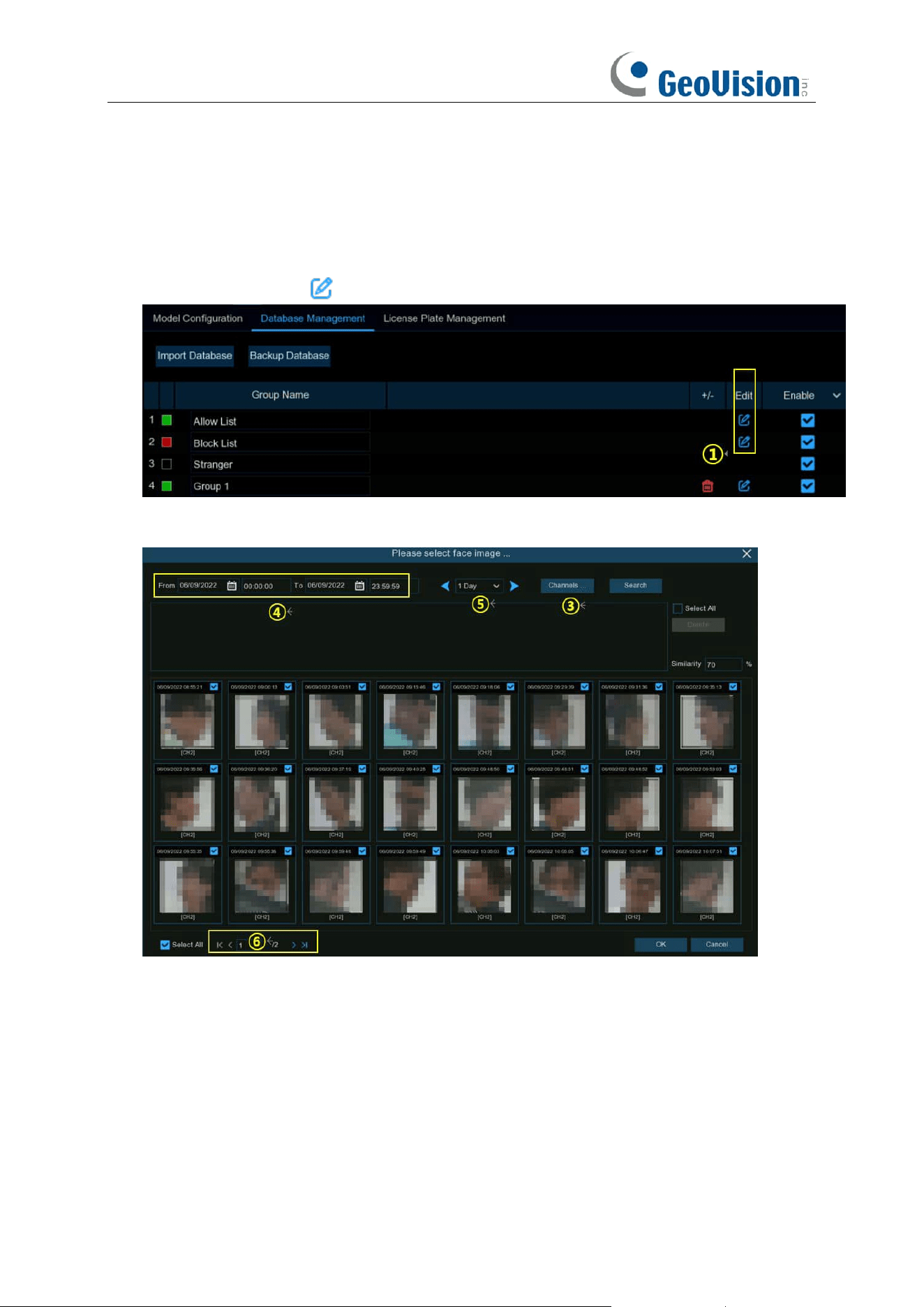
123
5.4.2.2.1 Creating Face Profiles from Local Storage Device
This section will show how to create face profiles from face images that have been captured and
stored on your NVR.
1. Click the "
Edit
" button of the group that you would like to create face profiles for.
2. From the Group window, click the "
Import
" button, then click the "
Local Storage Device
"
button.
This page appears.
3.
Channels:
All channels are set to search by default. You can specify the cameras you want to
search on.
4. Use the calendar to specify the date range.
5. Choose the day duration, and then use the arrow buttons to quickly display face images from
the previous or next day(s).
6. The search result will be displayed in the face list automatically. Use the arrow buttons to
display previous or next page of results.
7. You can narrow the search result by using the similarity:
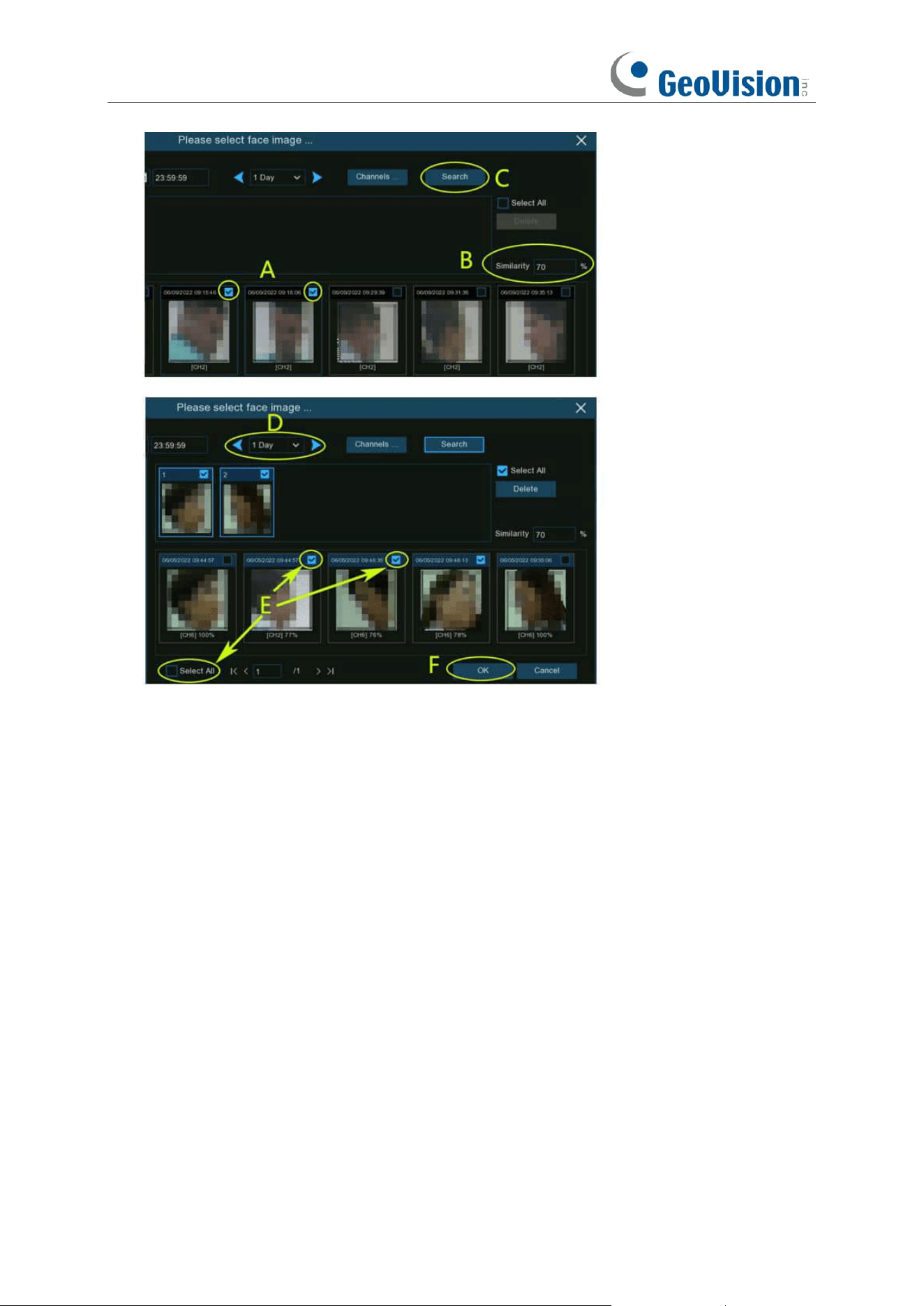
124
A. First, select the targeted face image(s) from the search result.
B. And then set the Similarity value. It is the face similarity threshold (%). The higher the
number is, the more precise the result will be.
C. Click Search button, the system will search for faces with an equal or greater similarity
than the specified value.
D. If you want to search from other days, choose the day duration, and then use the arrow
buttons to quickly display face images from the previous or next day(s).
E. Tick the checkbox to select individual face image, or tick "Select All" to select all face
images in current page of search result.
F. Once you've selected one or more face images, click the "OK" button. The system will go
to profile edit page.
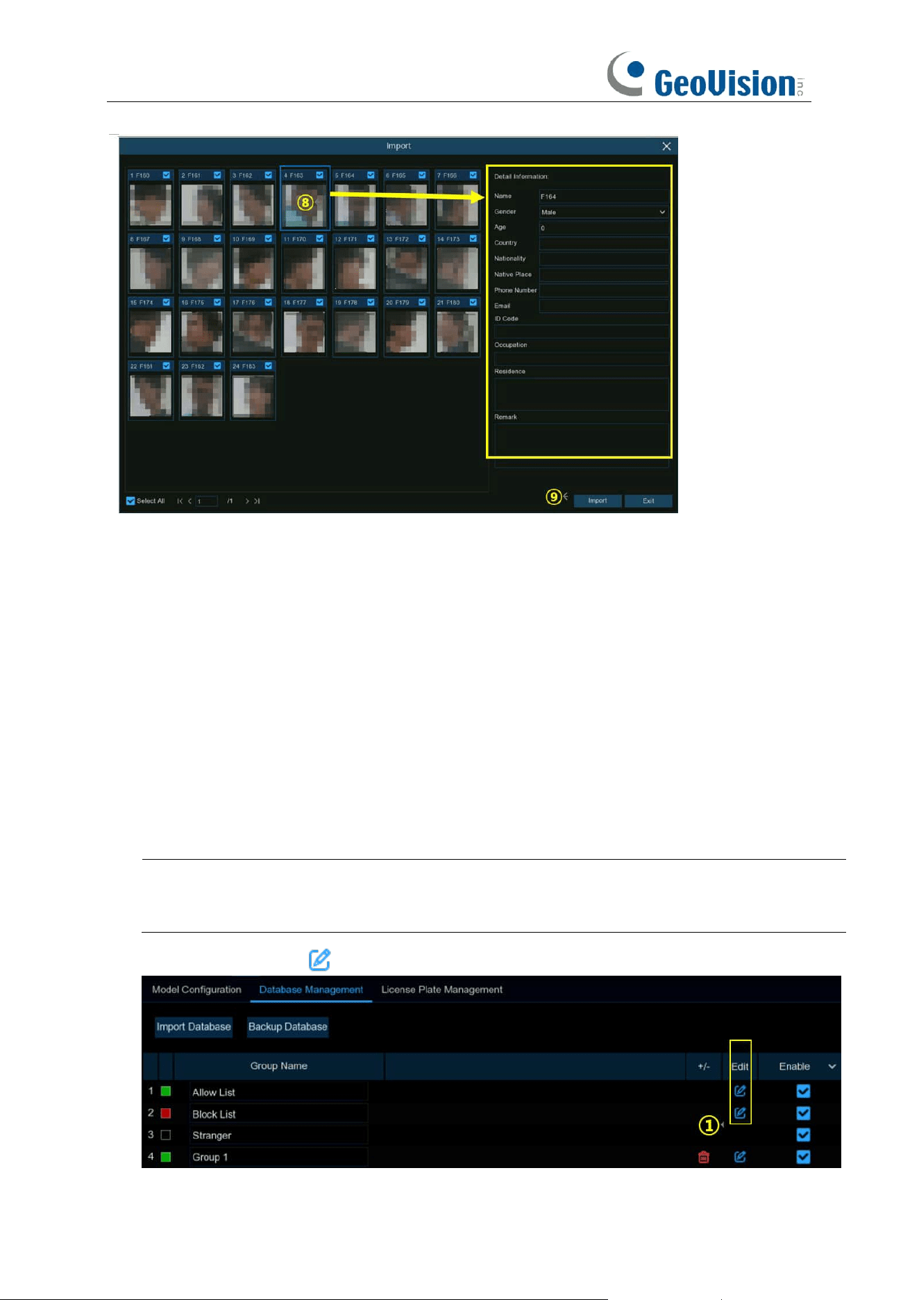
125
8. Click on a face image, then enter their identification details, such as the person's name and
age. By default, each face image is given a face ID as its name.
9. When finished, click "
Import
" button. The face profile is now created and assigned to the
group.
5.4.2.2.2 Creating Individual Face Profile from External Storage
Device
1. Copy the face images to your USB flash drive, and then insert the USB device into the USB
port of the NVR.
Note: The supported formats of face image are ".jpg", ".jpeg", ".png", and ".bmp". The supported
dimension of the image is from 80 x 80 to 800 x 800 pixels, and the maximum supported size is
500KB.
2. Click the "
Edit
" button of the group that you would like to create face profiles for.
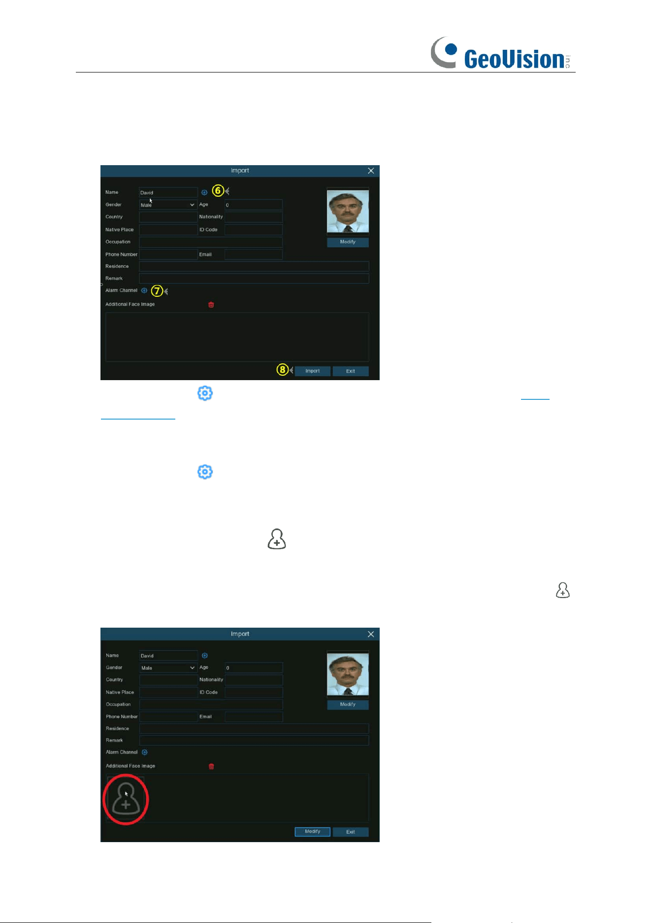
126
3. From the Group window, click the "
Import
" button, then click the "
External Storage Device
"
button.
4. Click on the face image you want to import, and click
OK
.
5. Edit the face profile of the people.
6. Click setup button to configure the voice prompt for the person. View more on 5.3.7.
Voice Prompts to learn how to configure this function. Note that the voice file you import here
takes effect only to this person. If you had set several periods of time, you would need to
import voice file for each period.
7. Click setup button to configure the
Alarm Channel
. The system will alert when the face
is detected and captured by the selected cameras.
8. Click
Import
button to import the face profile.
9. Now you will see an add button displayed in the
Additional Face Image
window. You
are able to add additional face images at different angles for the same person to improve face
recognition accuracy from local and/or external storage device by clicking the add button .
Maximum 10 images allowed to add.
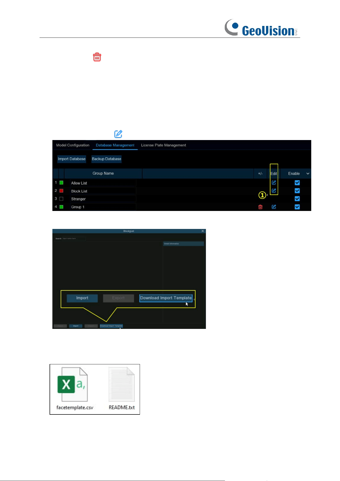
127
Click delete button to delete select image.
Click Modify button to finish, then click Exit button or right click your mouse to exit.
5.4.2.2.3 Creating Bulk Face Profiles from External Storage Device
If you want to create a batch of face profiles at once, please proceed as below:
1. Click the "
Edit
" button of the group that you would like to create face profiles for.
2. From the Group window, you will find the "
Download Import Template
" button.
3. Insert your USB flash drive, and then click the
Download Import Template button
, a zip file
named "import_template_enu.zip" will be downloaded into your USB flash drive.
4. Unzip the file, and you will get 2 files shown as below.
5. Create and name a new folder.
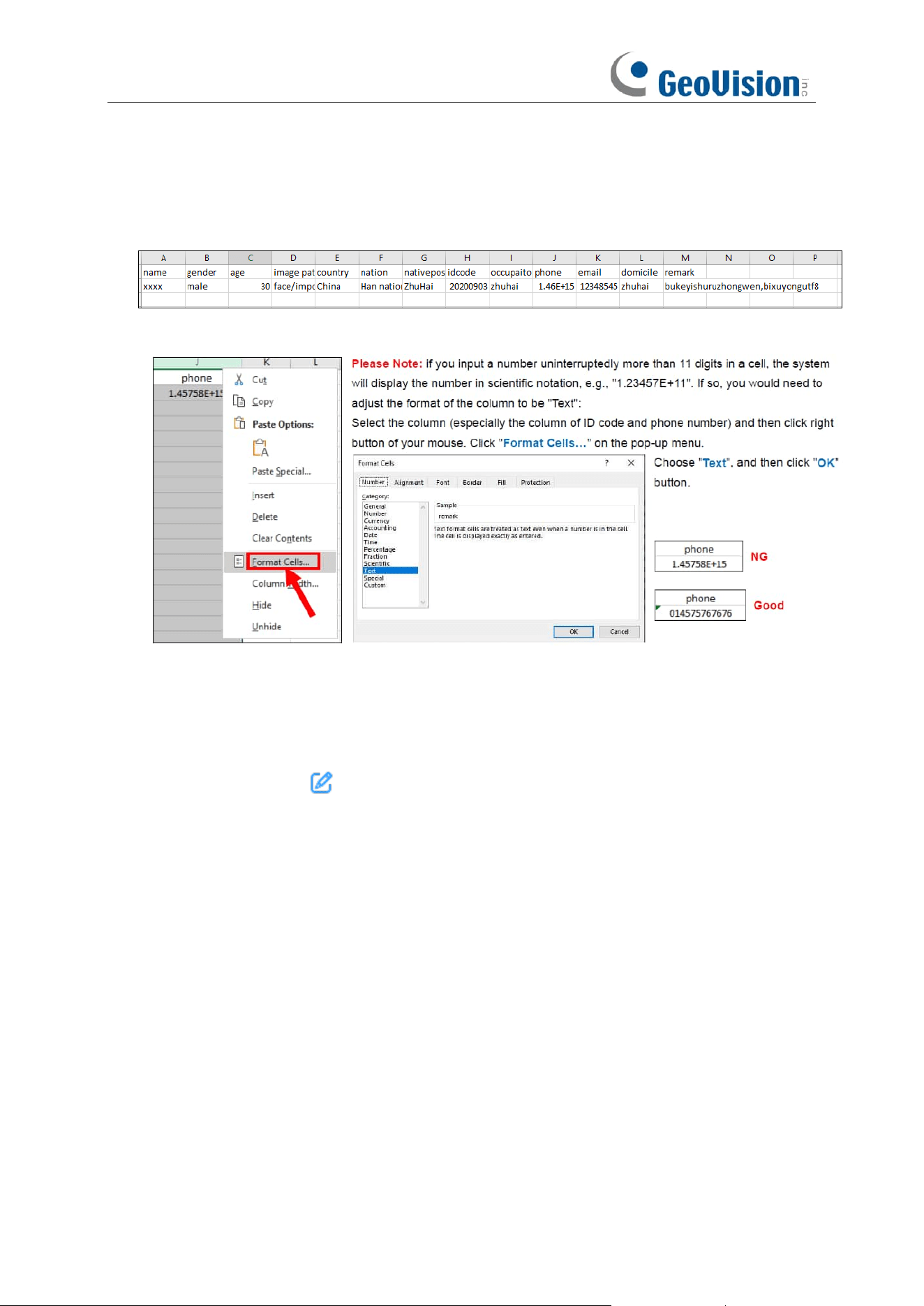
128
6. Copy the “facetemplate.csv” file and the face images into the folder. Make sure the formats of
face image are ".jpg", ".jpeg", ".png", or ".bmp", the dimension is between 80x80 and 800x800
pixels, and the size is no more than 500KB.
7. Double click on the “facetemplate.csv” file to run it with Excel. The content is shown as below:
8. Edit the cells according to your actual conditions as illustrated as below:
9. Save the .csv file. Make sure the file is saved as CSV UTF-8 type.
10. Copy the whole folder, including the face images and the "facetemplate.csv", and paste it to
your USB flash drive.
11. Insert the USB flash drive into the USB port of your NVR.
12. Click the "
Edit
" button of the group that you would like to create face profiles for.
13. From the Group window, click the "
Import
" button, then click the "
External Storage Device
"
button.
14. Find out and click on the "facetemplate.csv" file from your USB flash drive, and then click OK.
15. The face profiles are shown. Click
Import
button to import the face profiles into the NVR.
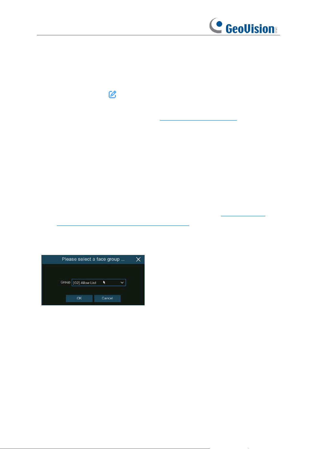
129
5.4.2.2.4 Editing Face Profiles
If you want to edit or delete a face profile, please proceed as below:
1. Click on the edit button of the group you want to edit
2. In the group edit page, you're able to execute below operations:
➔
Import:
To import face images. View on 5.4.2.2 Database Management.
➔
Export:
To export face image(s) to external USB flash drive.
⚫ Click
Export
button directly to export all face images in this group.
⚫ Click on one of the face images, and then click
Export
button to export an individual
image.
⚫ Click and hold the left button of your mouse, then drag the cursor to select multiple
images, and then click
Export
button to export the selected images.
3. Move the mouse cursor upon the image you want to edit and then click left button of your
mouse to select it. Click right button of your mouse to display a pop-up menu.
4. With the pop-up menu, you're able to:
➔
Edit:
Click to edit the face profile. Check how to edit the profile on 5.4.2.2.2 Creating
Individual Face Profiles from External Storage Device.
➔
Move To:
Click to move the face to another group.
Choose the targeted group, and then click OK.
➔
Delete:
To delete the select face profile.
➔
Detail Information:
Click to view the details of the selected face profile.
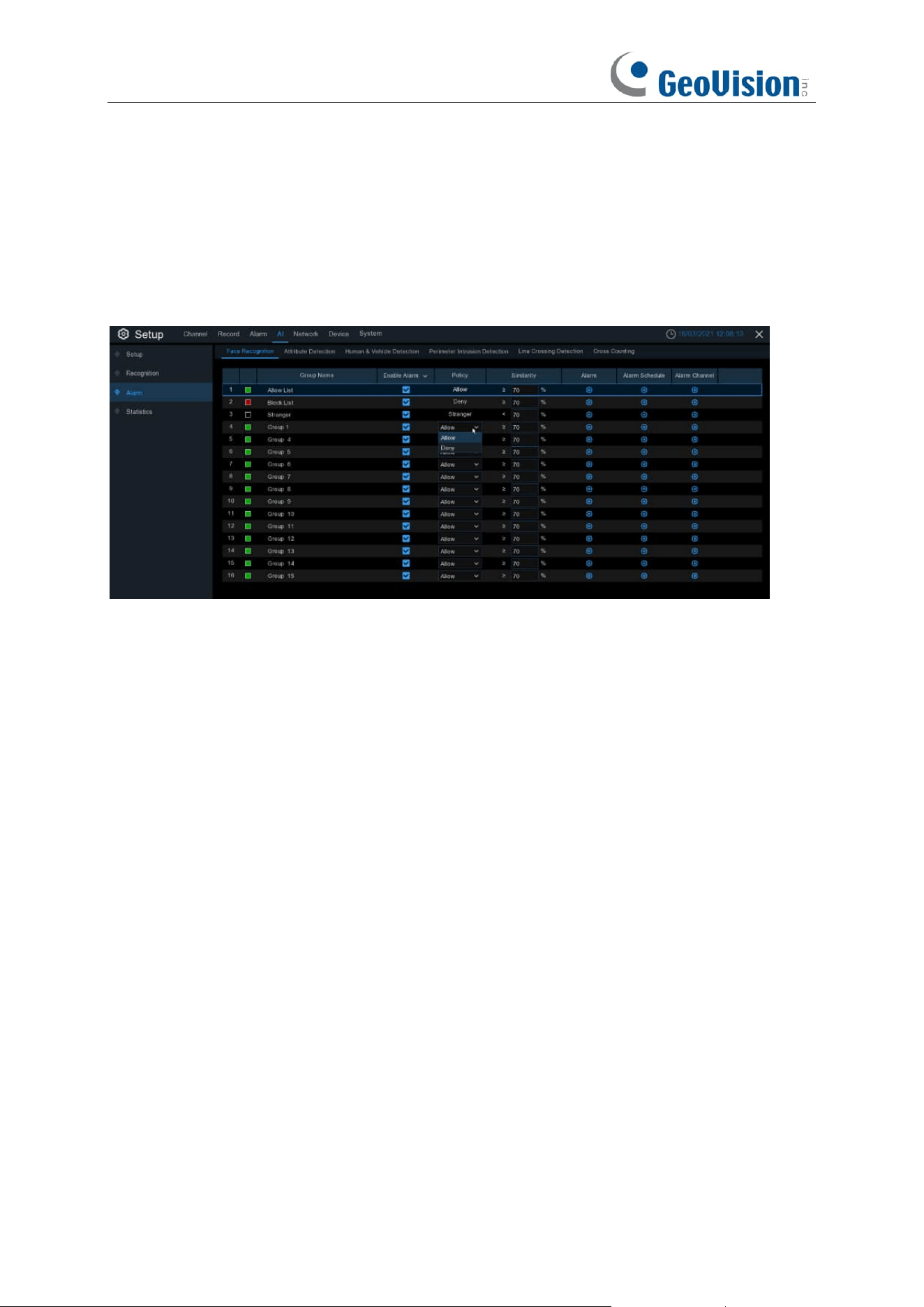
130
5.4.3 Alarm
5.4.3.1 FR (Face Recognition)
To configure alarm actions for different face groups when faces detected.
Enable Alarm: Tick the checkbox of the group(s) you want to enable alarm function. If the
checkbox isn't enabled, no actions specified for the group such as alarm notifications will be
actioned by your NVR. It is strongly recommended that the "Enable" checkbox for the "Stranger"
group remains ticked. This allows your NVR to save the images of every single face detected,
including those that do not match any existing face profiles to the database. You can use these
captured face images later to create or improve face profiles in the Allow List & Block List groups.
Policy: To set the group to be Allow list or Deny list.
Similarity: Set the similarity of comparison.
Alarm Channel: To choose which channel(s) will be applied to the alarm setting.
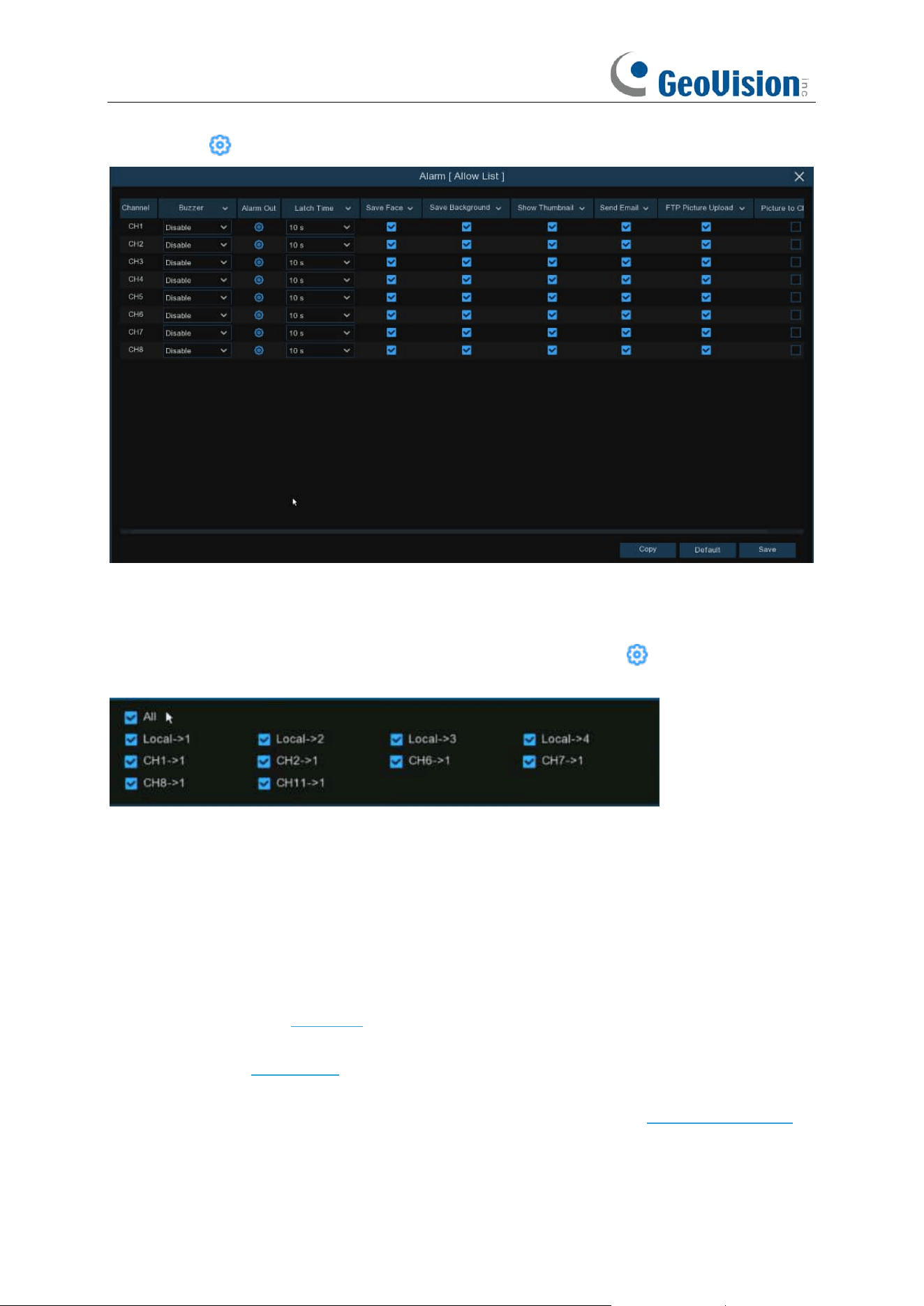
131
Alarm:
Click
to configure the alarm actions.
Buzzer:
The NVR can use its internal buzzer to emit an alarm tone. You can set the buzzer
duration in seconds when an alarm is triggered.
Alarm Out
: If your NVR or IP camera supports to connect external replay output devices, the
system can send an alert message to the external alarm devices. Click button, to choose the
external alarm devices:
⚫
Local
: The external alarm devices connected to the NVR.
⚫
CHx ->
1
: The external alarm devices connected to IP cameras.
Latch Time
: To configure the external alarm time when an alarm is triggered.
Face Capture:
To save the captured face.
Save Background:
To save the whole image when an alarm is triggered.
Show Thumbnail:
To pop-up the thumbnail image in live view screen when an alarm is triggered.
Send Email
: You can let the NVR to send you an auto-email when an alarm is triggered.
FTP Picture Upload
: To upload alarm images to FTP server when an alarm is triggered. To
enable FTP, please view 5.6.3 FTP.
Picture to Cloud:
To upload alarm images to Cloud server when an alarm is triggered. To enable
Cloud, please view 5.6.2 Cloud.
Voice Prompts:
If your NVR connects with a speaker, you can select a customized alert voice
when the detection is triggered. See how to add customized alert voice on 5.3.6 Voice Prompts.
Event Push Platform:
When an alarm is detected, it will send an alarm message to the third-party
platform that the device is connected to.
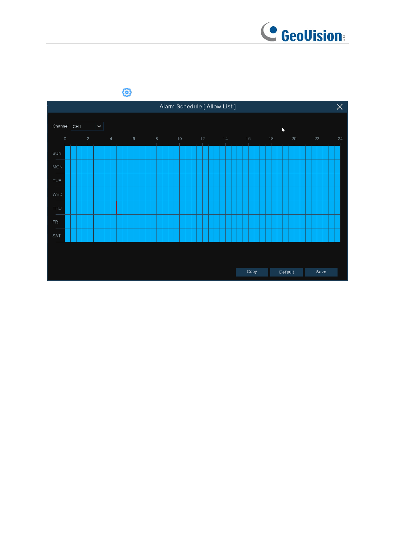
132
Default:
Click "
Default
" to revert to default settings.
Copy:
Use the "
Copy
" function to apply all settings to the other connected cameras.
Save:
Click "
Save
" to save settings.
Alarm Schedule:
Click icon to configure the alarm schedule for each channel.
Channel
: Select the channel to set its capture parameters.
To set the schedule, choose one channel then drag the cursor to mark the slots. The blue blocks in
the time slots will be active for alarm. The schedule is valid only for the selected channel each time
when you set. If you want to use the same schedule for other channels, use Copy function. Click
Save to save your settings.
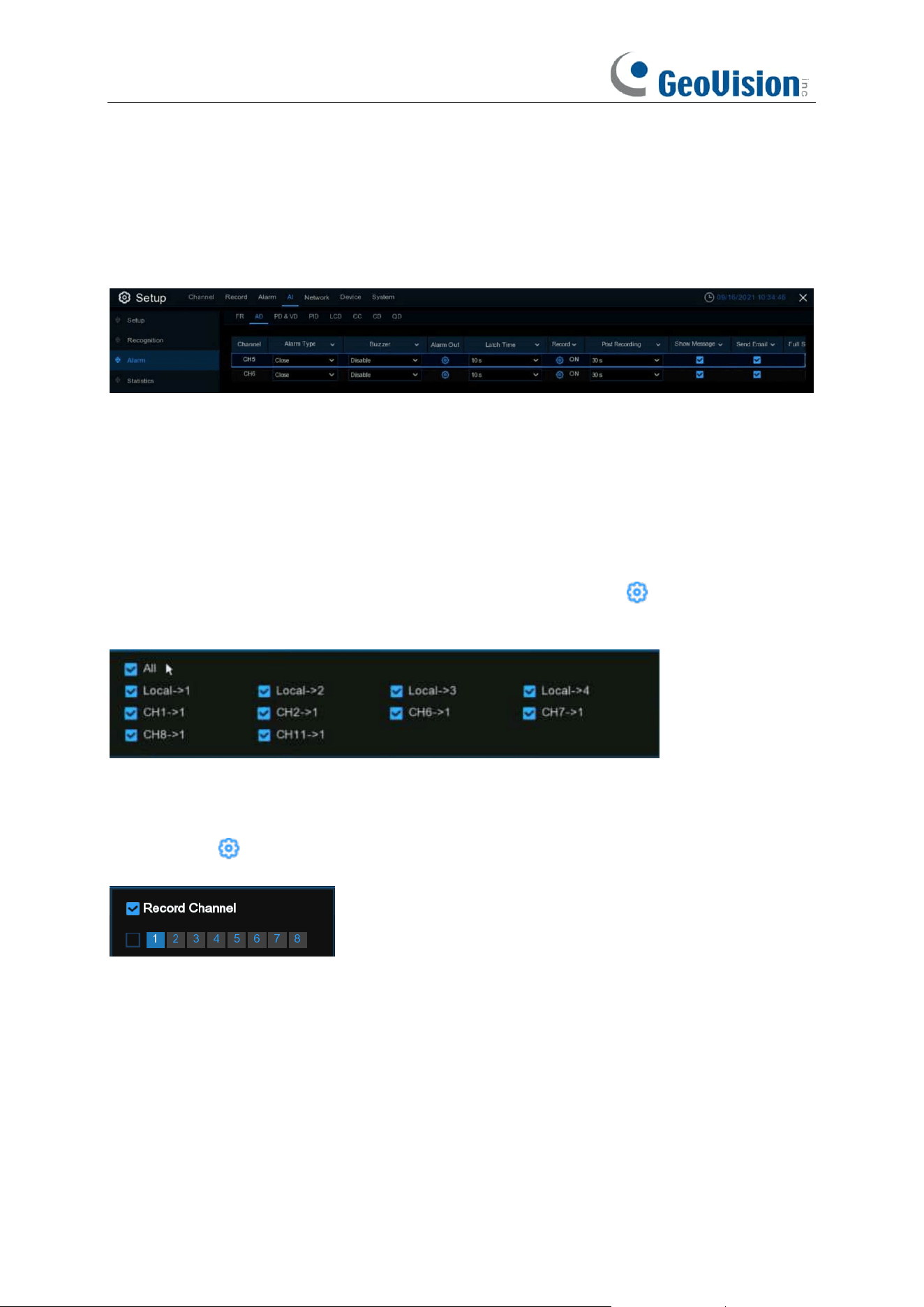
133
5.4.3.2 AD (Attribute Detection) / Face Attributes
Attribute detection is a function to detect people’s facial features and send an alarm according to
the settings. This is applicable for Face Detection function.
Alarm Type: Select the alarm trigger condition. If the selection is “No Mask”, the NVR will send an
alarm if it detects a person doesn’t wear a face mask. If the selection is “Wear Mask”, the NVR will
send an alarm if it detects a person wears a face mask. Select “Close” to disable the face mask
detection.
Buzzer:
The NVR can use its internal buzzer to emit an alarm tone. You can set the buzzer
duration in seconds when an alarm is triggered.
Alarm Out: If your NVR or IP camera supports to connect external replay output devices, the
system can send an alert message to the external alarm devices. Click button, to choose the
external alarm devices:
⚫
Local
: The external alarm devices connected to the NVR.
⚫
CHx ->
1
: The external alarm devices connected to IP cameras.
Latch Time
: To configure the external alarm time when an alarm is triggered.
Record
: Click icon and choose which channel(s) you want to record when the alarm is
triggered.
Post Recording
: You can set how long after an event occurs that the NVR will continue to record.
The recommended recording length is 30 seconds but it can be set higher up to 5 minutes.
Show Message
: Check the box to display “
S
” icon on the live view screen when the alarm is
triggered.
Send Email
: You can let the NVR to send you an auto-email when an alarm is triggered.
Full Screen
: If this function is enabled and an alarm is triggered in a channel, you will see its full
screen images in live view.
Event Push Platform:
When an alarm is detected, it will send an alarm message to the third-party
platform that the device is connected to.
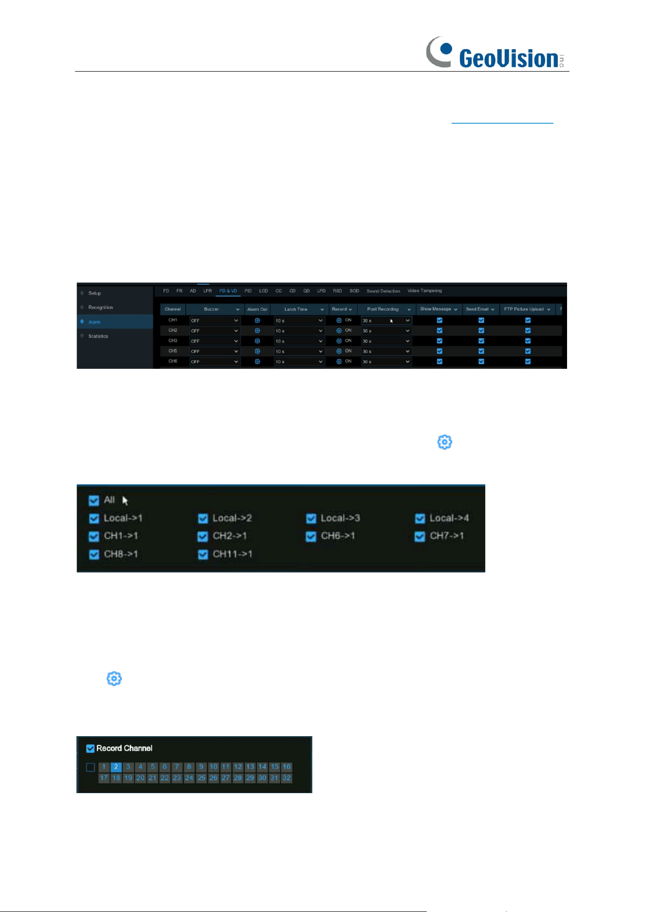
134
Voice Prompts: If your NVR connects with a speaker, you can select a customized alert voice
when the detection is triggered. See how to add customized alert voice on 5.3.6 Voice Prompts.
Default: Click "Default" to revert to default settings.
Copy: Use the "Copy" function to apply all settings to the other connected cameras.
Apply: Click "Apply" to save settings.
5.4.3.3 PD & VD (Human & Vehicle Detection) Alarm
To configure alarm actions when human beings and/or vehicles are detected.
Buzzer: When alarm event is detected, you can enable the NVR's buzzer to alert you for a
predetermined amount of time. Click the drop-down menu to select a time.
Alarm Out: If your NVR or IP camera supports to connect external replay output devices, the
system can send an alert message to the external alarm devices. Click button, to choose the
external alarm devices:
Local: External alarm devices connected to the NVR.
CHx->1: External alarm devices connected to IP cameras.
Latch Time: To configure the external alarm time when the detection is triggered.
Record: This option instructs your NVR to trigger additional cameras to start recording when
motion is detected. Click the drop-down arrow to choose all channels to be recorded or not.
Click button, click the "Record Channel" checkbox to enable recording. Click the checkbox in
front of the channel number to select all channels or click on the individual camera number that
you want to trigger for recording.

135
Post Recording: This option instructs your NVR to record for a set time after an event has
occurred. For most instances, the default selection will be suitable, however, you can change this
if you wish.
Show Message: When the detection is triggered, the alarm icon will appear on screen.
Send Email: An email alert will be sent when alarm event is detected. Click the checkbox if you
want to disable this.
FTP Picture Upload: Click the checkbox to copy snapshots to your ftp server when the detection
is triggered.
FTP Video Upload: Click the checkbox to copy videos to your ftp server when the detection is
triggered.
Picture to Cloud: Click the checkbox to copy snapshots to the cloud via Dropbox or Google Drive
when the detection is triggered.
Video to Cloud: Click the checkbox to copy videos to the cloud via Dropbox or Google Drive
when the detection is triggered.
Full Screen: Click the checkbox to view the camera full-screen in Live View mode when the
detection is triggered.
Event Push Platform:
When an alarm is detected, it will send an alarm message to the third-party
platform that the device is connected to.
Voice Prompts: If your NVR connects with a speaker, you can select a customized alert voice
when the detection is triggered. See how to add customized alert voice on 5.3.6 Voice Prompts.
Default: Click "Default" to revert to default settings.
Copy: Use the "Copy" function to apply all settings to the other connected cameras.
Apply: Click "Apply" to save settings.
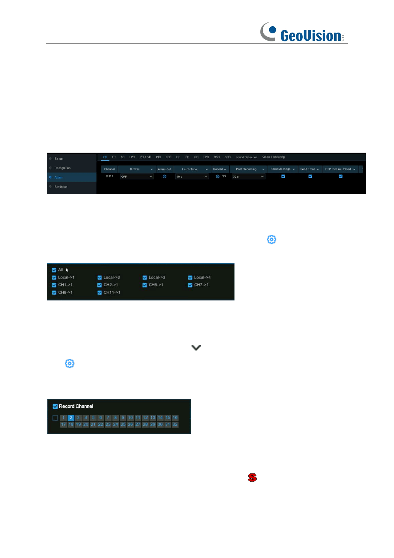
136
5.4.3.4 FD/PID/LCD/CC/CD/QD/RSD/SOD/Sound Detection/Video
Tampering Alarm/Intrusion/Region Entrance/Exiting Alarms
The setting method to configure alarm actions is same for FD, PID, LCD, CC, CD, QD, RSD, SOD,
Sound Detection and Video Tampering.
Buzzer: When alarm event is detected, you can enable the NVR's buzzer to alert you for a
predetermined amount of time. Click the drop-down menu to select a time.
Alarm Out: If your NVR or IP camera supports to connect external replay output devices, the
system can send an alert message to the external alarm devices. Click button, to choose the
external alarm devices:
Local: External alarm devices connected to the NVR.
CHx->1: External alarm devices connected to IP cameras.
Latch Time: To configure the external alarm time when the detection is triggered.
Record: This option instructs your NVR to trigger additional cameras to start recording when
motion is detected. Click the drop-down arrow to choose all channels to be recorded or not.
Click button, click the "Record Channel" checkbox to enable recording. Click the checkbox in
front of the channel number to select all channels or click on the individual camera number that
you want to trigger for recording.
Post Recording: This option instructs your NVR to record for a set time after an event has
occurred. For most instances, the default selection will be suitable, however, you can change this
if you wish.
Show Message: When the detection is triggered, the alarm icon will appear on screen.
Send Email: An email alert will be sent when alarm event is detected. Click the checkbox if you
want to disable this.

137
FTP Picture Upload: Click the checkbox to copy snapshots to your ftp server when the detection
is triggered.
FTP Video Upload: Click the checkbox to copy videos to your ftp server when the detection is
triggered.
Picture to Cloud: Click the checkbox to copy snapshots to the cloud via Dropbox or Google Drive
when the detection is triggered.
Video to Cloud: Click the checkbox to copy videos to the cloud via Dropbox or Google Drive
when the detection is triggered.
Full Screen: Click the checkbox to view the camera full-screen in Live View mode when the
detection is triggered.
Event Push Platform:
When an alarm is detected, it will send an alarm message to the third-party
platform that the device is connected to.
Voice Prompts: If your NVR connects with a speaker, you can select a customized alert voice
when the detection is triggered. See how to add customized alert voice on 5.3.6 Voice Prompts.
Default: Click "Default" to revert to default settings.
Copy: Use the "Copy" function to apply all settings to the other connected cameras.
Apply: Click "Apply" to save settings.
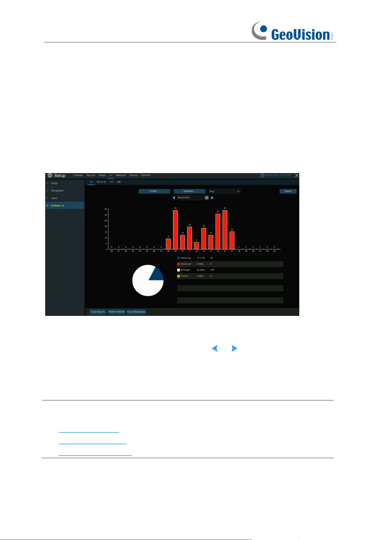
138
5.4.4 Statistics
You are able to check and manage the statistics of FR (Face Recognition), PD&VD (Pedestrian
and Vehicle Detection), CC (Cross Counting), and HM (Heat Map) in this section.
5.4.4.1 FR (Face Recognition)
You can check the face recognition statistics in a certain period.
1. Choose the group(s) and channel(s).
2. Select the period from day, week, month, quarter and year.
3. Click the calendar icon to choose the date, and click or button to move to last or next
period.
4. The statistics will be displayed in pie chart and column chart.
5. Click
Export
button if you want to export the data to USB memory.
Note:
See the following sections for the functions of
Face Search, Repeat Visitors,
and
Face
Attendance:
7.1.9.1 Face Search
7.1.9.4 Repeat Visitors
7.1.9.5 Face Attendance
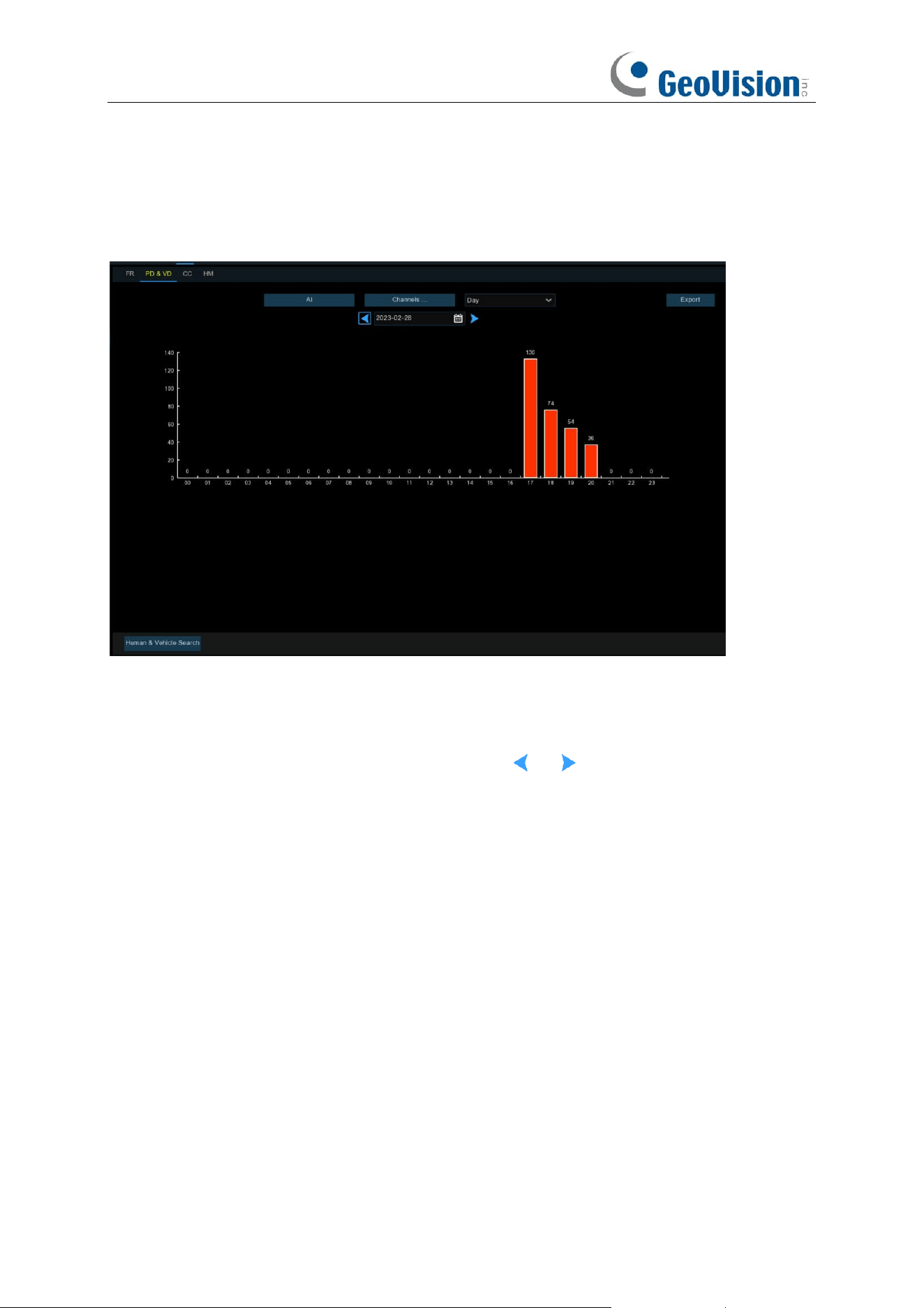
139
5.4.4.2 PD&VD (Pedestrian and Vehicle Detection)
You can check the face recognition statistics in a certain period.
1. Choose the detection type in Intelligent / AI.
2. Choose the channel(s).
3. Select the period from day, week, month, quarter and year.
4. Click the calendar icon to choose the date, and click or button to move to last or next
period.
4. The statistics will be displayed in pie chart and column chart.
5. Click
Export
button if you want to export the data to USB memory.
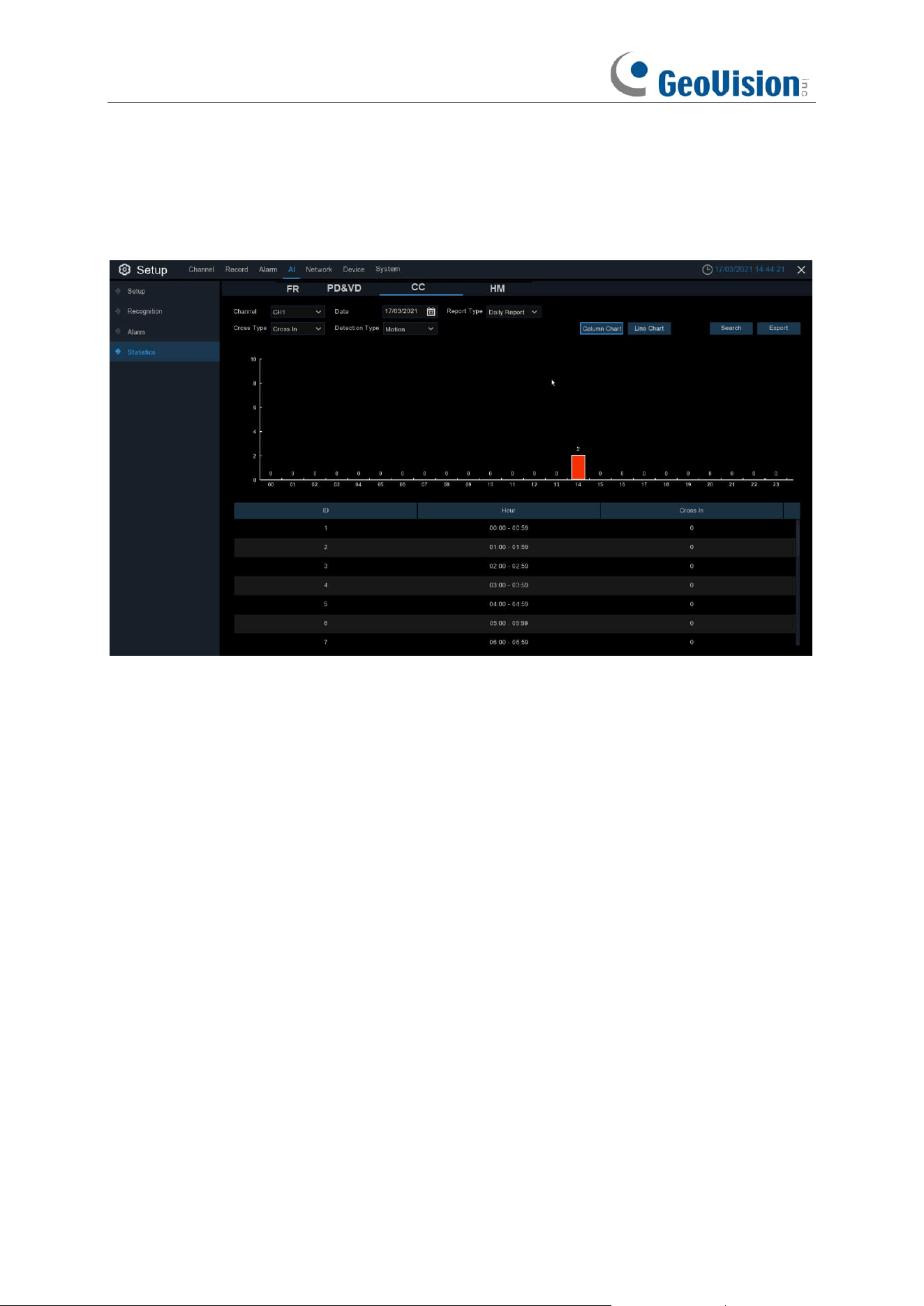
140
5.4.4.3 CC (Cross-Counting)
You can check the cross counting statistics in a certain period.
1. Choose the channel & date.
2. Choose the Report Type: Daily, Weekly, Monthly or Annually.
3. Choose the Cross Type: Cross In or Cross Out.
4. Choose the Detection Type: Motion, Person or Vehicle.
5. Click Search button, the result will be displayed in either Column Chart or Line Chart.
6. Click
Export
button if you want to export the data to USB memory.
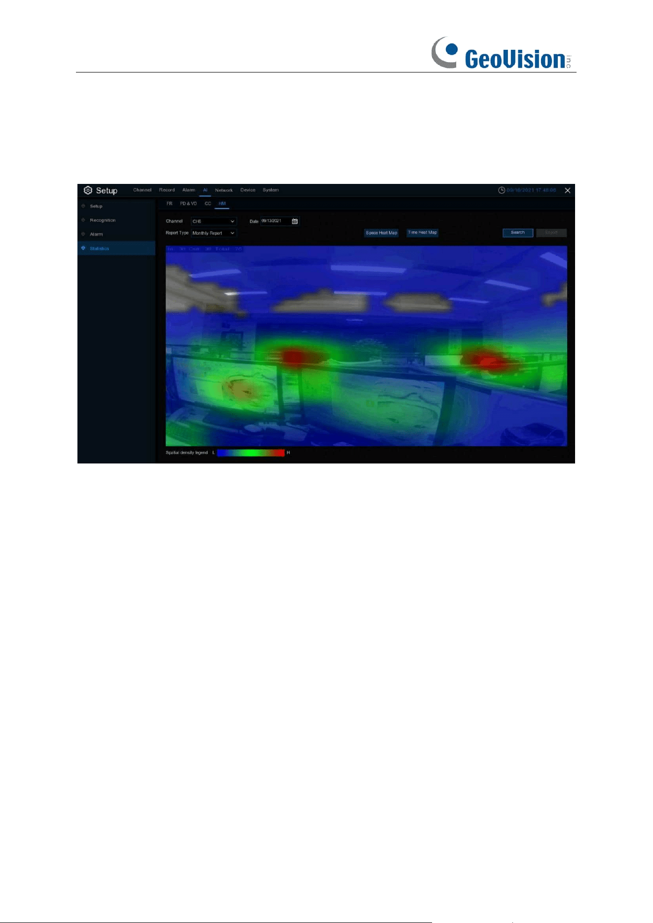
141
5.4.4.4 HM (Heat Map)
You can check the heat map statistics in a certain period.
1. Choose the channel & date.
2. Choose the Report Type: Daily, Weekly, Monthly or Annually.
3. Set the Start Hour / End Hour.
4. Click Search button, the result will be displayed in either Column Chart or Line Chart.
5. The result can be displayed by Space & Time.
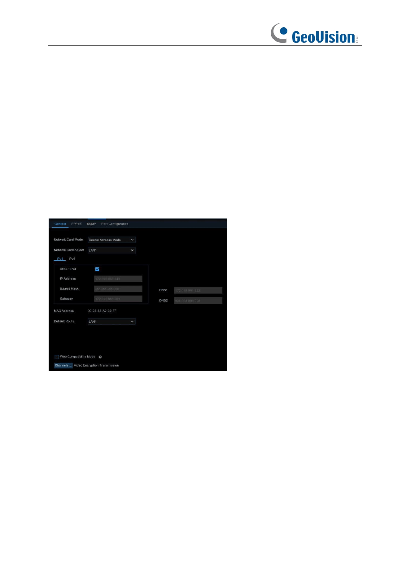
142
5.5 Network
This menu allows you to configure network parameters, such as PPPoE, DHCP. The most
common types are DHCP. Most probably your network type is DHCP, unless the network is
manually addressed. If you need an authentication user name and password to the Internet, then
choose PPPoE.
5.5.1 General
5.5.1.1 General
Network Card Mode: Used for switching between Single Address Mode and Double Address
Mode. After switching succeeds, the NVR is restarted.
Single Address Mode: In Single Address Mode, two network ports are bound to one IP address.
You can select this mode to increase the bandwidth and form a redundant network card array to
share the load. If one network port fails, the other network port will immediately take over all the
load and the service will not be interrupted.
Double Address Mode: In Double Address Mode, two network ports are configured with IP
addresses and gateways of different network segments respectively, and the two network ports
are operating independently of each other. The LAN port for connecting the external network
should be configured as the default route.
Network Card Select: Used for setting whether to display the network parameter information of
LAN1 or LAN2. This option is not available in Single Address Mode.

143
DHCP IPv4: To connect a router that allows DHCP, select this option. the router automatically
assigns all the IPv4 network parameters to the NVR. If you do not select this option, the IP address,
subnet mask, gateway, and DNS will automatically change back to the setting when you
unchecked the option last time. (Note: Currently, DHCP IPv6 is not supported.)
IP Address: The IP address is the identification of the NVR in the network. An IP address consists
of four numbers between 0 and 255, separated by periods, for example, 192.168.001.100.
Subnet Mask: A subnet mask is a network parameter that defines the range of IP addresses that
can be used in the network. A subnet address consists of four numbers, separated by periods, for
example, 255.255.000.000.
Gateway: The IP address of the gateway of the network where the device is located. The default
value is 192.168.001.001.
DNS1/DNS2: DNS1 is the preferred DNS server and DNS2 is the alternate DNS server.
IPv6 Address: The IPv6 address is the identification of the NVR in the network. An IPv6 address
consists of eight numbers between 0 and FFFF, separated by colons. For example,
ABCD:EF01:2345:6789:ABCD:EF01:2345:6789.
Subnet Prefix Length: Subnet prefix length.
IPv6 Gateway: The IP address of the IPv6 gateway of the network where the device is located.
Default Route: In the dual-access mode, set the LAN port to the external network as the default
route. Note that this option is unavailable for Single Address Mode.
Web Compatibility Mode: If the device cannot be accessed through the Web, you can select this
option to have a try. Insecure encryption is used when this option is enabled. Thus you must be
careful in selecting this option.
Channels…: Click this button to set the channels for encrypting and transmitting video streams to
clients.
Video Encryption Transmission:
Note:
1. In Single Network Card Mode, the device can access the network through either of the two
LAN ports. If both LAN ports are connected to network cables, they must be connected to
the same switch.
2. In Double Network Card Mode, the two LAN ports cannot be connected to the same switch.
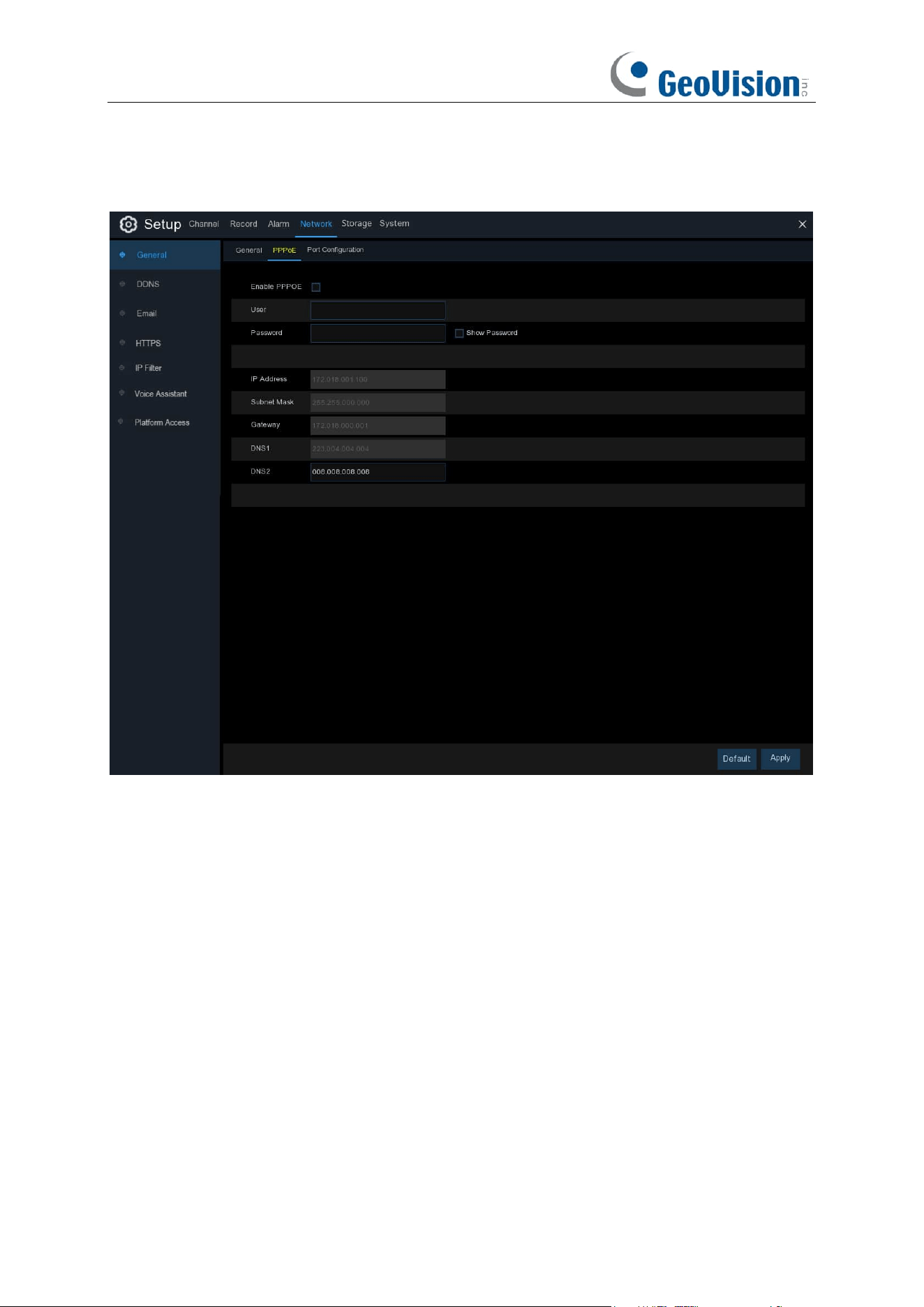
144
5.5.1.2 PPPoE
This is an advanced protocol that allows the NVR to connect to the network more directly via DSL
modem.
Check the “Enable PPPOE” box, and then enter the User name & Password of the PPPoE.
Click
Apply
to save, system will reboot to active the PPPoE setting.
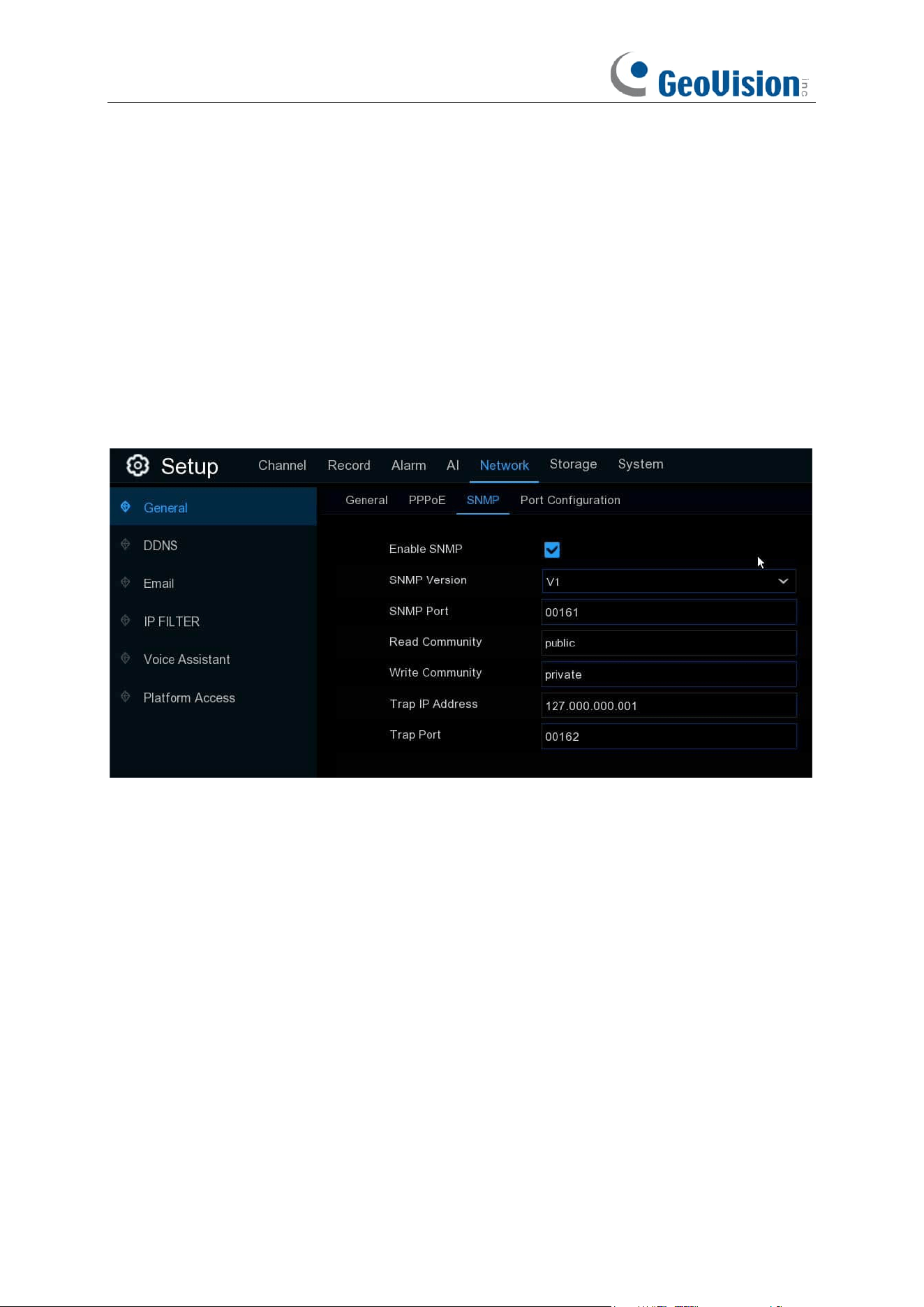
145
5.5.1.3 SNMP
SNMP (Simple Network Management Protocol) is an Internet Standard protocol for collecting and
organizing information about managed devices on IP networks and for modifying that information
to change device behavior.
With the SNMP, you are allowed to connected the NVR with 3
rd
party network management
platform and acquire the NVR information, such as firmware version number, device type,
resolution, frame rate, etc.
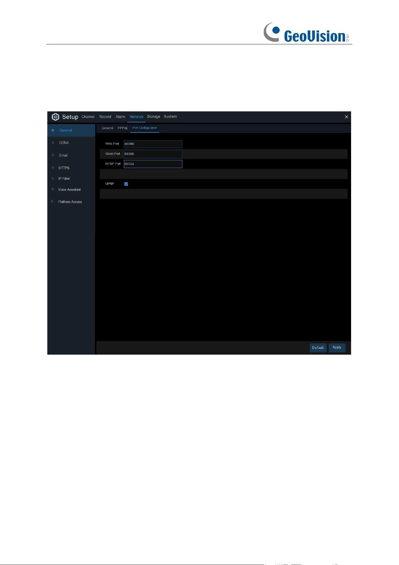
146
5.5.1.4 Port Configuration
GV-RNVR256G0-N
http/https/rtsp: This port is mostly used to log into your NVR via webpage or 3
rd
party streaming
player by rtsp protocol. If the default port number (80) is used by other devices in the network, you
may need to change it.
Client Port: This is the internal port that your NVR will use to send information through. This
particular port number (9000) is not used by many devices, however, if you have another NVR-like
device, you may need to change it.
Internal Port: It is mostly used to access the NVR from the same LAN.
External Port: It is mostly used to access the NVR from a different LAN or internet. You need to
forward the external ports to internet from your router manually If you want to access your NVR via
internet, which would be a little more complicated for users without network knowledge. Using
UPNP would make it easier.
Web Port
: This is the port that you will use to log in remotely to the NVR (e.g. using the Web
Client). If the default port 80 is already taken by other applications, change it.
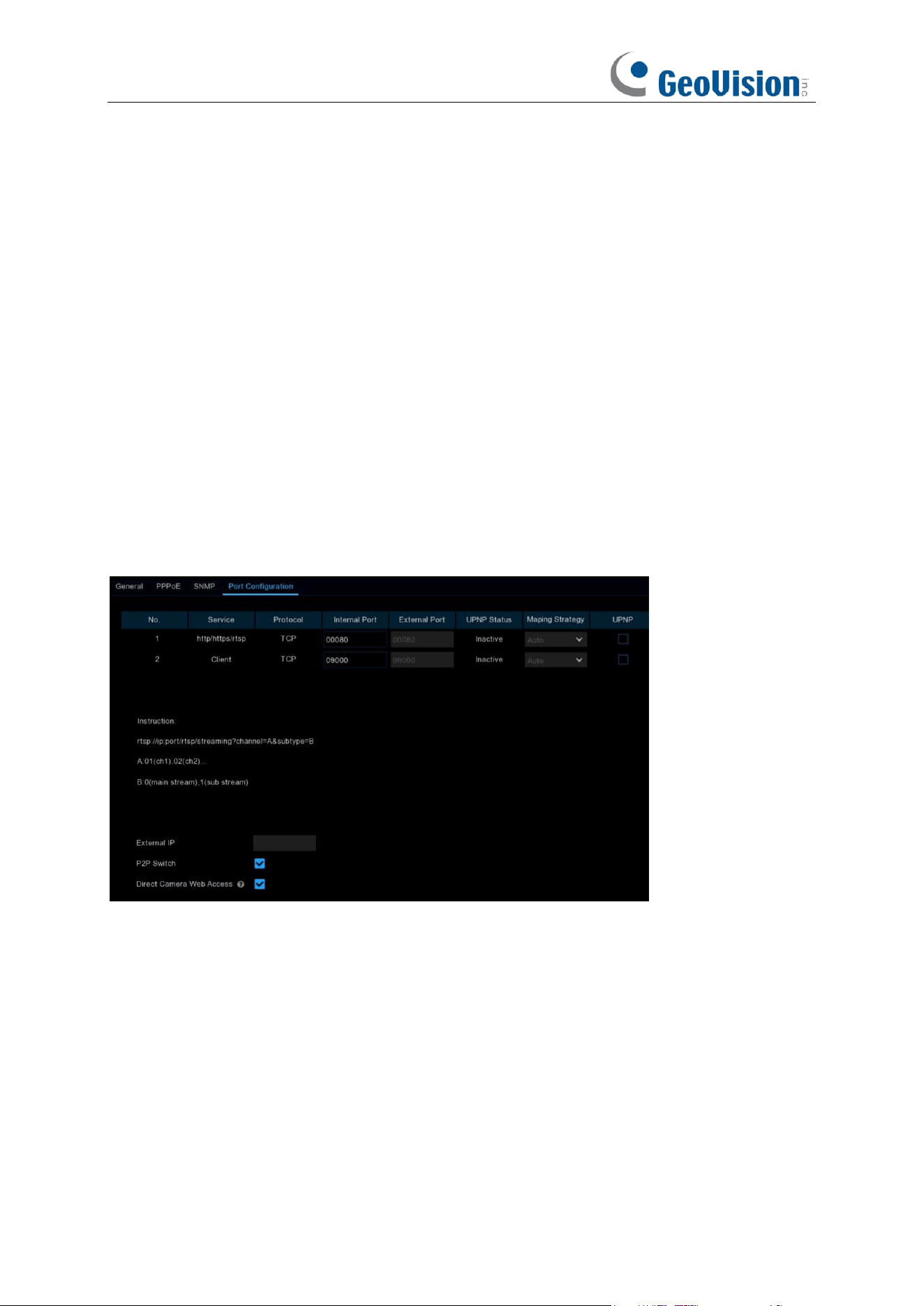
147
RTSP Port:
Default is
554, if the default port 554 is already taken by other applications, change it.
UPNP is a network protocol designed to allow network-connected devices to automatically obtain
and forward the ports from the router.
1. Tick the checkbox of "
UPNP
".
2. Choose "
Auto
" on Mapping Strategy, the external port will be automatically obtained and
forwarded from your router.
3. If you want to change the external port by manual, choose "
Manual
" on Mapping Strategy and
then modify the port accordingly.
P2P Switch: Click to enable P2P function.
IP Camera Hyperlink: This advanced feature allows to visit the webpage of the IP cameras which
are connected to the NVR when you're accessing in the NVR's webpage. Tick the checkbox to
enable this feature and click "Apply" to save, you will find the hyperlink of each capable IP camera
on the NVR's webpage. This is not a universal feature for all IP cameras. It varies with models or
firmware versions.
GV-RNVRL810-P / GV-RNVR3240-N
http/https/rtsp:
This port is mostly used to log into your NVR via webpage or 3
rd
party streaming
player by rtsp protocol.
UPNP:
If you want to log in remotely to the NVR using Web Client via different router/LAN, you
need to complete the port forwarding in your router. Enable this option if your router supports the
UPNP. In this case, you do not need to configure manually port forwarding on your router. If your
router does not support UPNP, make sure the port forwarding is completed manually in your
router.
Mapping Strategy:
Select "Manual" for mapping type, users can edit and set the external port
(the port on the router); if it is "Auto", a random external port (different from the internal port) will be
mapped.
External IP:
The device's external IP.
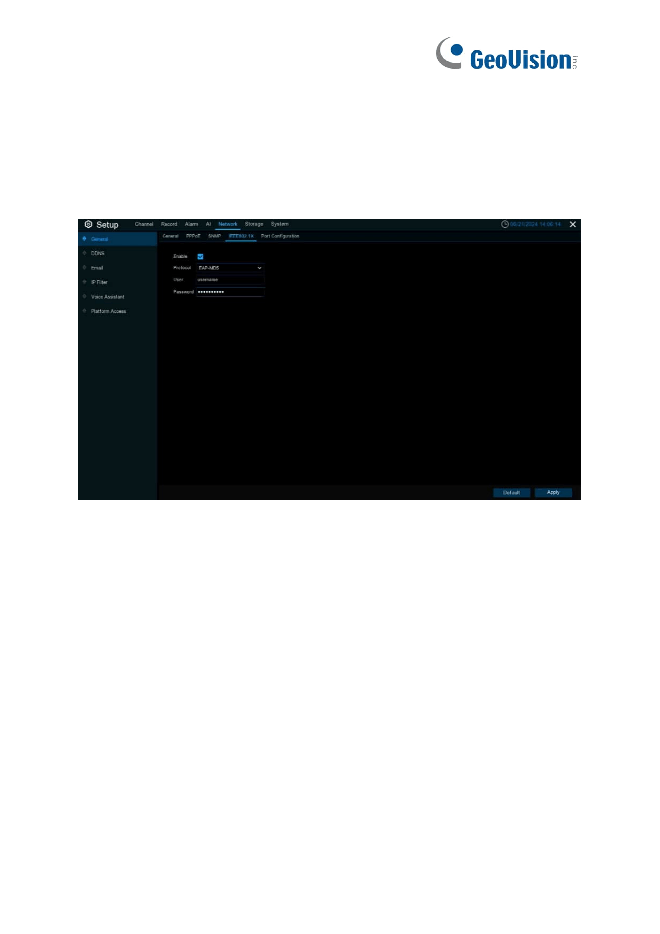
148
P2P Switch:
P2P switch, when off, users will not be able to access the device with P2P ID.
Direct Camera Web Access: Enable to access IPC's WEB page via hyperlink on NVR's Web side.
5.5.1.5 IEEE802.1X
Enable: Used to turn on or off IEEE802.1X.
Protocol: Select the desired authentication method.
Username / Password: The username and password must be the same with the username
and password applied for and registers in the authentication server.
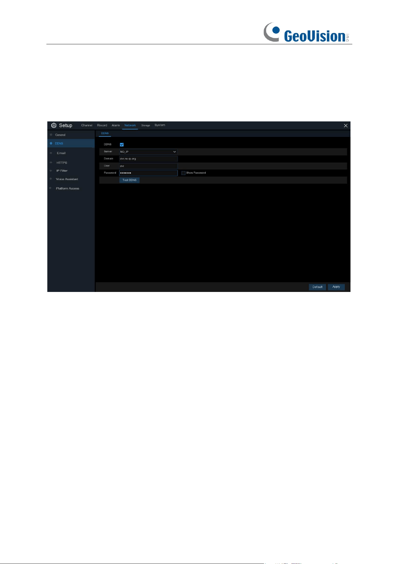
149
5.5.2 DDNS
This menu allows you to configure DDNS settings. The DDNS provides a static address to simplify
remote connection to your NVR. To use the DDNS, you first need to open an account on the
DDNS service provider’s web page.
DDNS
: Check to enable DDNS.
Server
: Select the preferred DDNS server (DDNS_3322, DYNDNS, NO_IP, CHANGEIP,
DNSEXIT, GeoDDNS).
Domain
: Enter the domain name you created on the DDNS service provider’s web page. This will
be the address you type in the URL box when you want to connect remotely to the NVR via PC.
Fox example: NVR.no-ip.org.
User/Password
: Enter the user name and password you obtained when creating an account on
the DDNS service provider’s web page.
After all parameters are entered, click
Test DDNS
to test the DDNS settings. If the test result is
“Network is unreachable or DNS is incorrect”, check whether the network works fine, or the DDNS
information is correct or not.
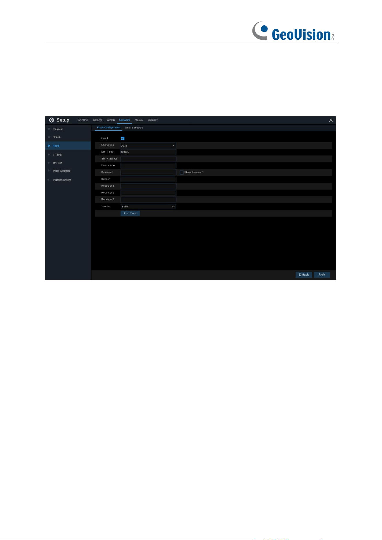
150
5.5.3 Email
This menu allows you to configure email settings. Complete these settings if you want to receive
the system notifications on your email when an alarm is triggered, HDD becomes full, HDD is in
error state, or Video Loss occurs.
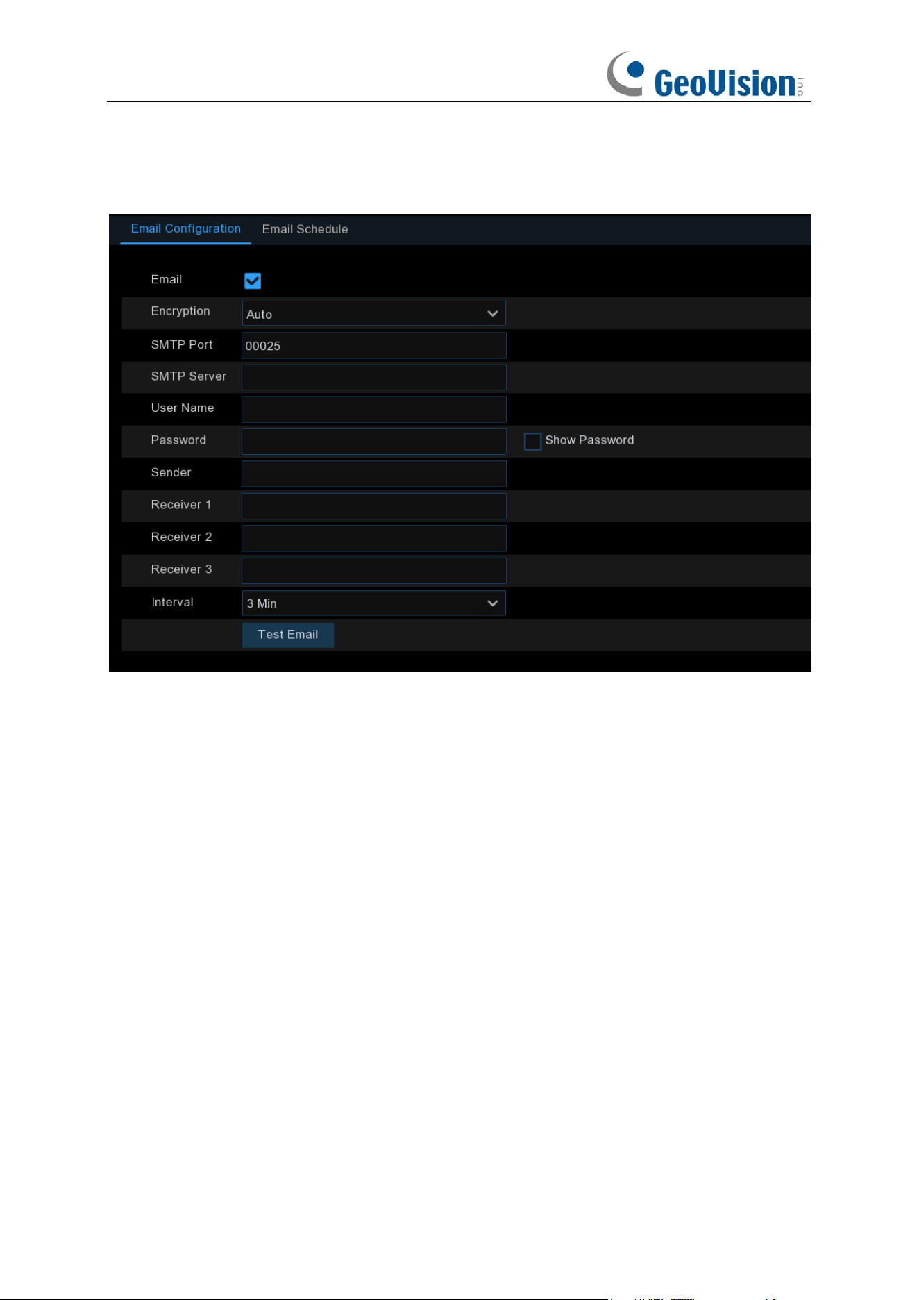
151
5.5.3.1 Email Configuration
Email
: Check to enable.
Encryption
: Enable if your email server requires the SSL or TLS verification. If you are not sure,
set to be
Auto.
SMTP Port
: Enter the SMTP port of your email server.
SMTP Server:
Enter the SMTP server address of your email.
User Name
: Enter your email address.
Password
: Enter the password of your email.
Receiver 1~3
: Enter the email address where you want to receive the event notifications from the
NVR.
Interval
: Configure the length of the time interval between the notification emails from the NVR.
To make sure all settings are correct, click
Test Email
. The system sends an automated email
message to your inbox. If you received the test email, it means the configuration parameters are
correct.
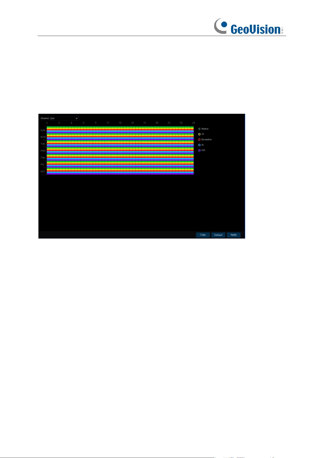
152
5.5.3.2 Email Schedule
If email alerts are enabled on your NVR, alerts would be emailed 24 hours as default. You can
change the schedule when your NVR can send those alerts. For example, you may only want to
receive alerts during the day but not in the evening. An alternative schedule can be created for
each camera.
The color codes on email schedule have the following meanings:
Green
: Slot for Motion detection.
Yellow
: Slot for I/O Alarm (optional).
Red
: Slot for Exception (HDD full, HDD error, or Video Loss).
Blue
: Slot for Intelligent Analysis / AI detection.
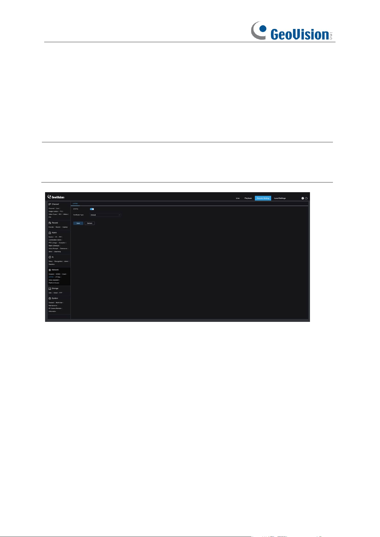
153
5.5.4 HTTPS
HTTPS is an HTTP channel aimed at security, ensuring the security of the transmission process
through encrypted transmission and identity authentication based on HTTP.
You can configure the HTTPS protocol on this menu. Devices can be connected using the HTTPS
protocol.
Note:
1. This function is only available on the Web interface.
2. Use the following command to access the Web interface of the NVR: https:<IP
address>:<port>.
Certificate Type
: Authentication types, including Default and Custom. Users can use their own
certificates to connect devices with the Custom option.
Certificate: Under the Custom type, select a custom certificate.
Key: Under the Custom type, select a custom Key file.
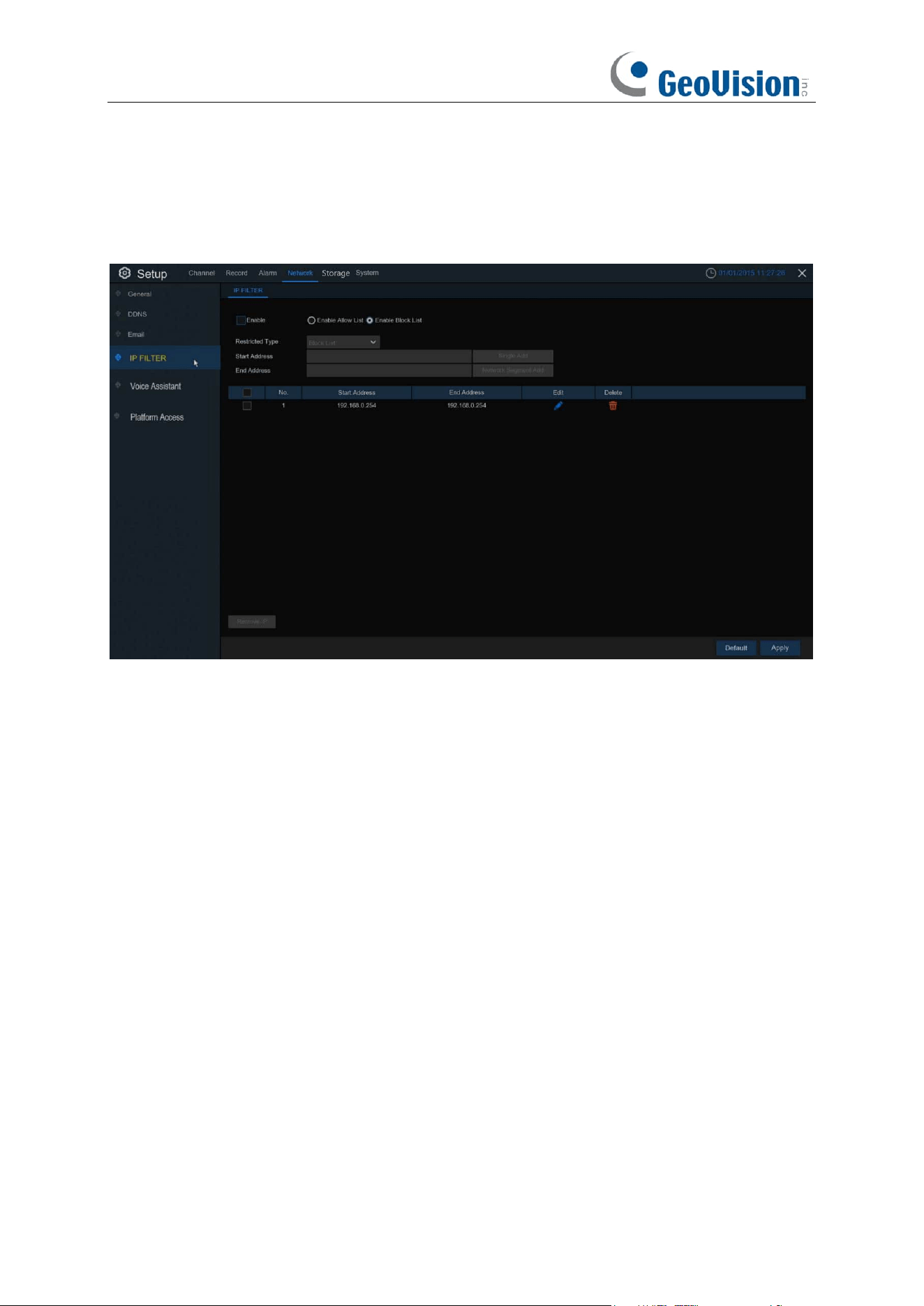
154
5.5.5 IP Filter
This function allows you to set a allow list and black list so that only the IP addresses on the allow
list can connect to the device.
Enable: Enable or disable the IP filter function. Once enabled, you can select to filter the IP
addresses by allow list or black list.
Restricted Type: Select the list (Black List or Allow List) to finish relevant configurations.
Single Add: Enter the IP address to add to the list.
Network Segment Add:
Start Address: Input the Start Address.
End Address: Input the End Address.
Allow List: It includes a range of IP addresses you define that indicates what IP addresses are
allowed to access your NVR to prevent unauthorized IP addresses from logging into your NVR.
1. Tick the checkbox of Enable to activate the IP filter function.
2. Click on the ratio button of "
Enable Allow List
".
3. Choose "
Allow List
" from "
Restricted Type
".
4. If you want to add individual IP address into the allow list, click "
Single IP Address
" to input
the IP address. If you want to add a block of IP addresses, click "
IP Address Range
" to input
the start IP address and end IP address.
5. Click
Save
. Only IP address(es) from the Allow List can access your NVR now.

155
Block List: It includes a range of IP addresses you define that indicates what IP addresses are
forbidden to access your NVR to prevent unauthorized IP addresses from logging into your NVR.
1. Tick the checkbox of Enable to activate the IP filter function.
2. Click on the ratio button of "
Enable Block List
".
3. Choose "
Block List
" from "
Restricted Type
".
4. If you want to add individual IP address into the allow list, click "
Single IP Address
" to input
the IP address. If you want to add a block of IP addresses, click "
IP Address Range
" to input
the start IP address and end IP address.
5. Click
Save
. IP address(es) from the Block List is forbidden to access your NVR now.
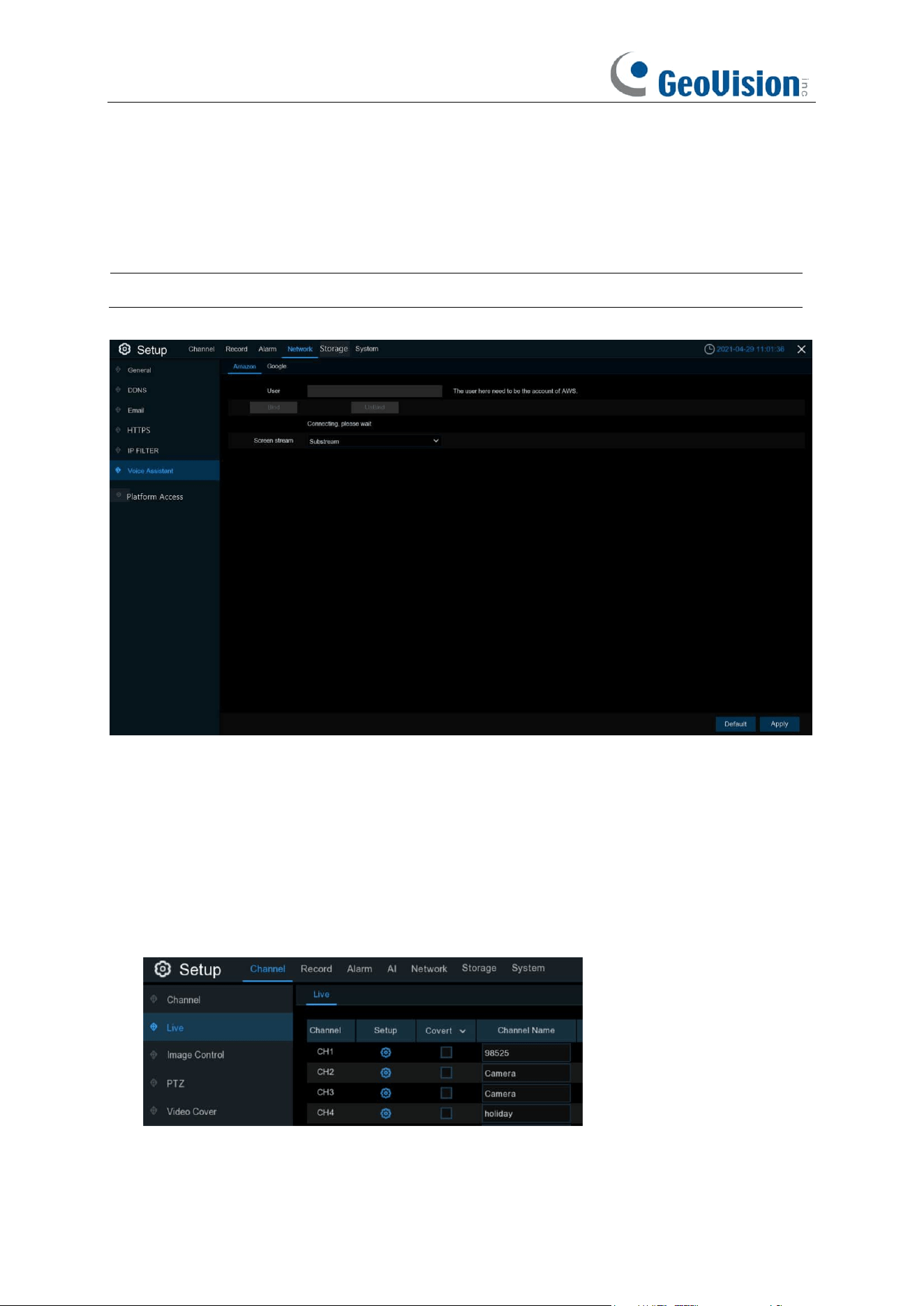
156
5.5.6 Voice Assistant
The voice assistant function allows to connect your NVR to your GoogleCast or Amazon Fire TV
Stick, and cast the real-time surveillance images on your TV monitor by voice control.
Note: This function only supports a maximum of one channel live view.
5.5.6.1 Voice Assistant with Amazon Fire TV Stick
1. Input your Amazon account, and the click "Bind" button to bind your Amazon account. Then
choose the video stream you want to cast on your TV monitor.
2. Go to Channel –> Live menu, and give a Channel Name which is easy to call to the channel(s)
you want to cast on your TV monitor.
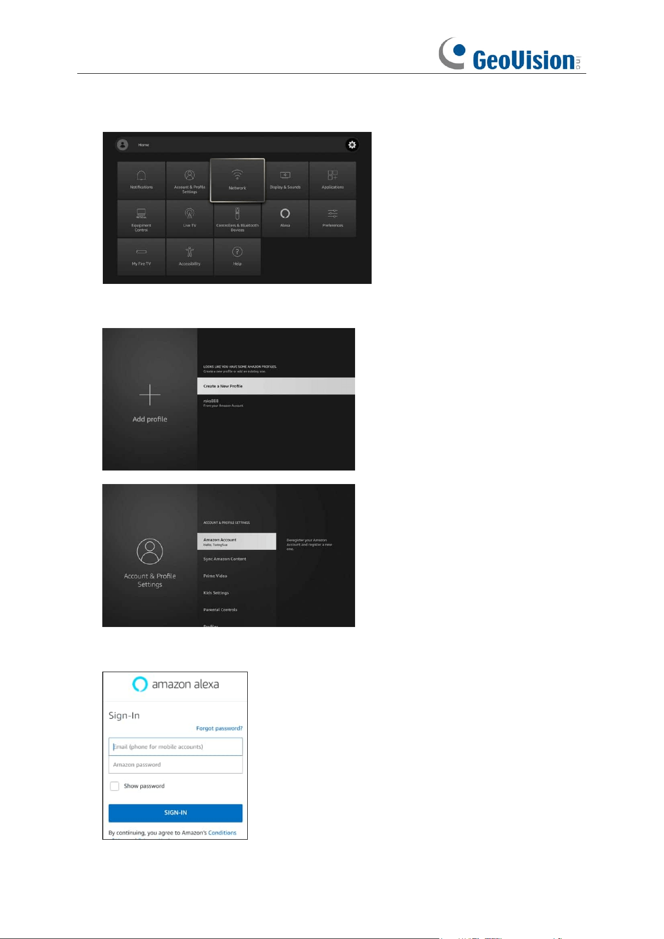
157
3. Connect the Fire TV Stick to your TV monitor, and power on it. Connect the Fire TV Stick to
the Wi-Fi which is in the same LAN with your NVR.
4. To use your existing profile or add a new profile and login your Amazon account which is
same as the one you bind to the NVR.
5. Search and install Amazon Alexa to your mobile phone from app store, and then login with the
Amazon account which is same as the one you bind to the NVR.
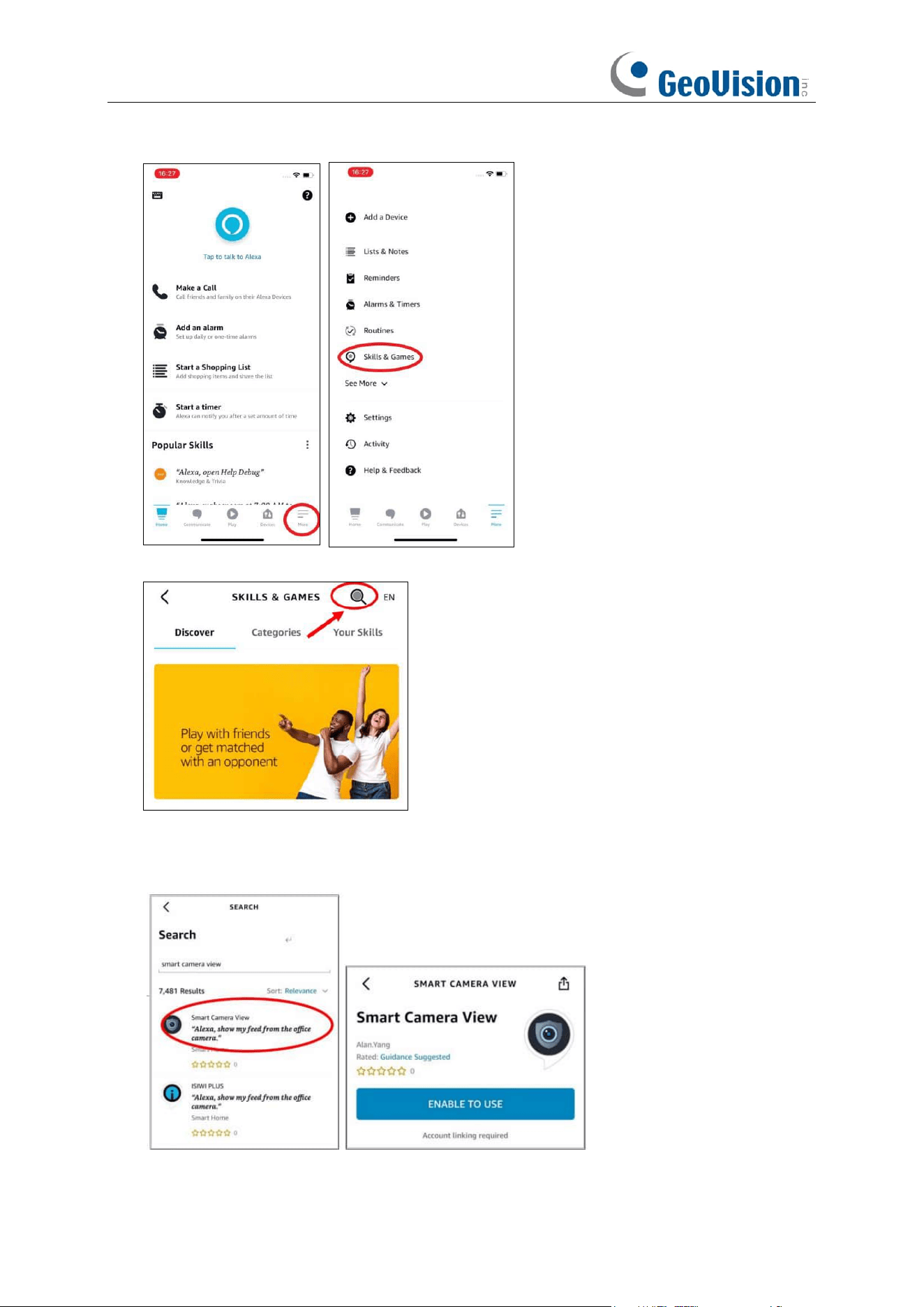
158
6. Touch "More", and then touch "Skills & Games".
7. Touch the search icon on the top right corner.
8. Input the keyword: smart camera view, and search.
9. Touch the "Smart Camera View" app in the search result list. And then Touch "ENABLE TO
USE".
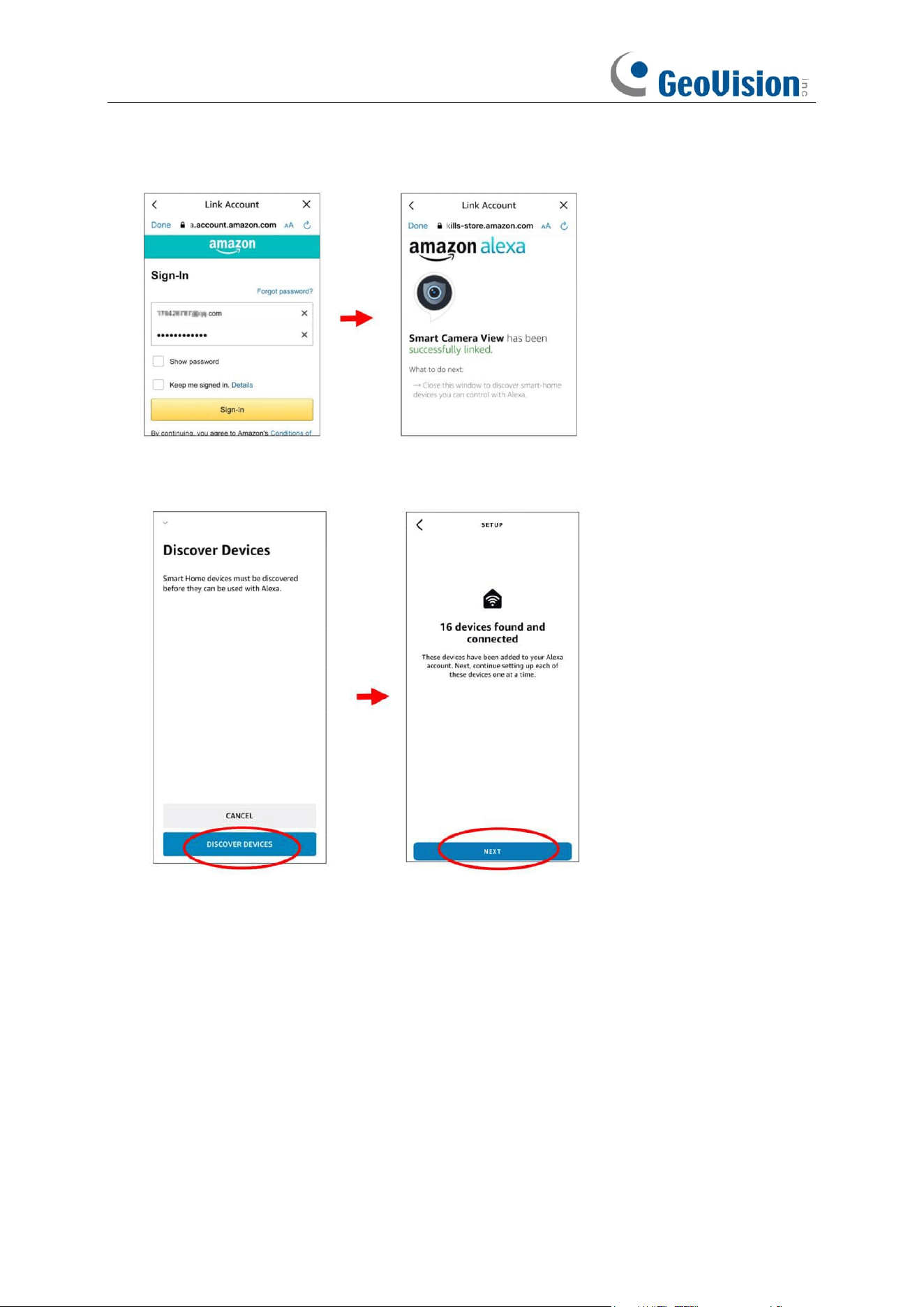
159
10. You would need to link your Amazon account. Sign in the Amazon account which is same as
the one you bind to the NVR. Touch "Done" after the skill is successfully linked.
11. Touch "DISCOVER DEVICES" and wait a moment for the app to search the cameras. Touch
"Next" when the devices were found and connected.
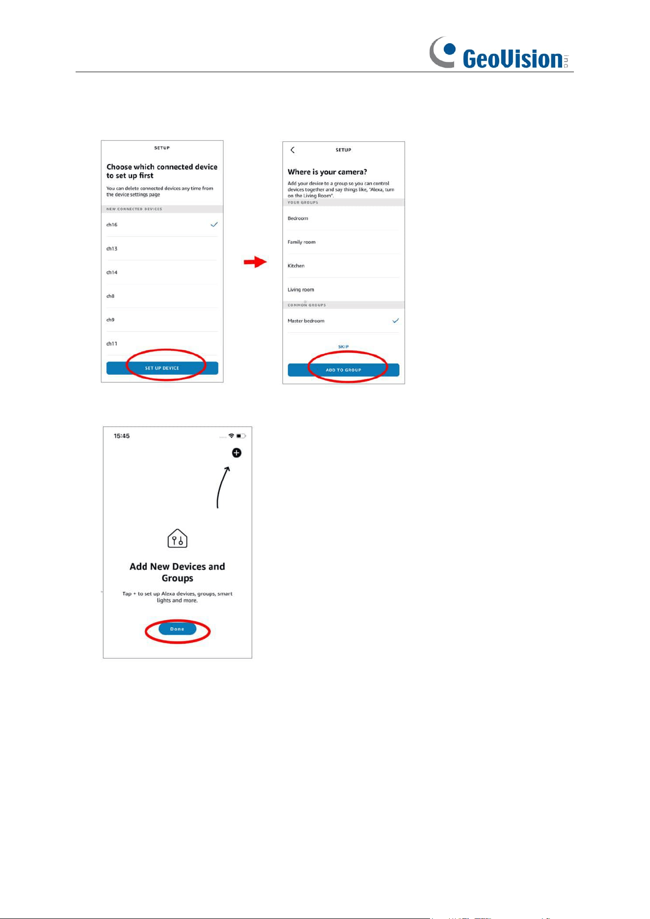
160
12. Choose one of the devices and then touch "SET UP DVICE". You can add the camera to a
group or skip.
13. Repeat setup 12 to add all cameras and then touch "Done" to finish.
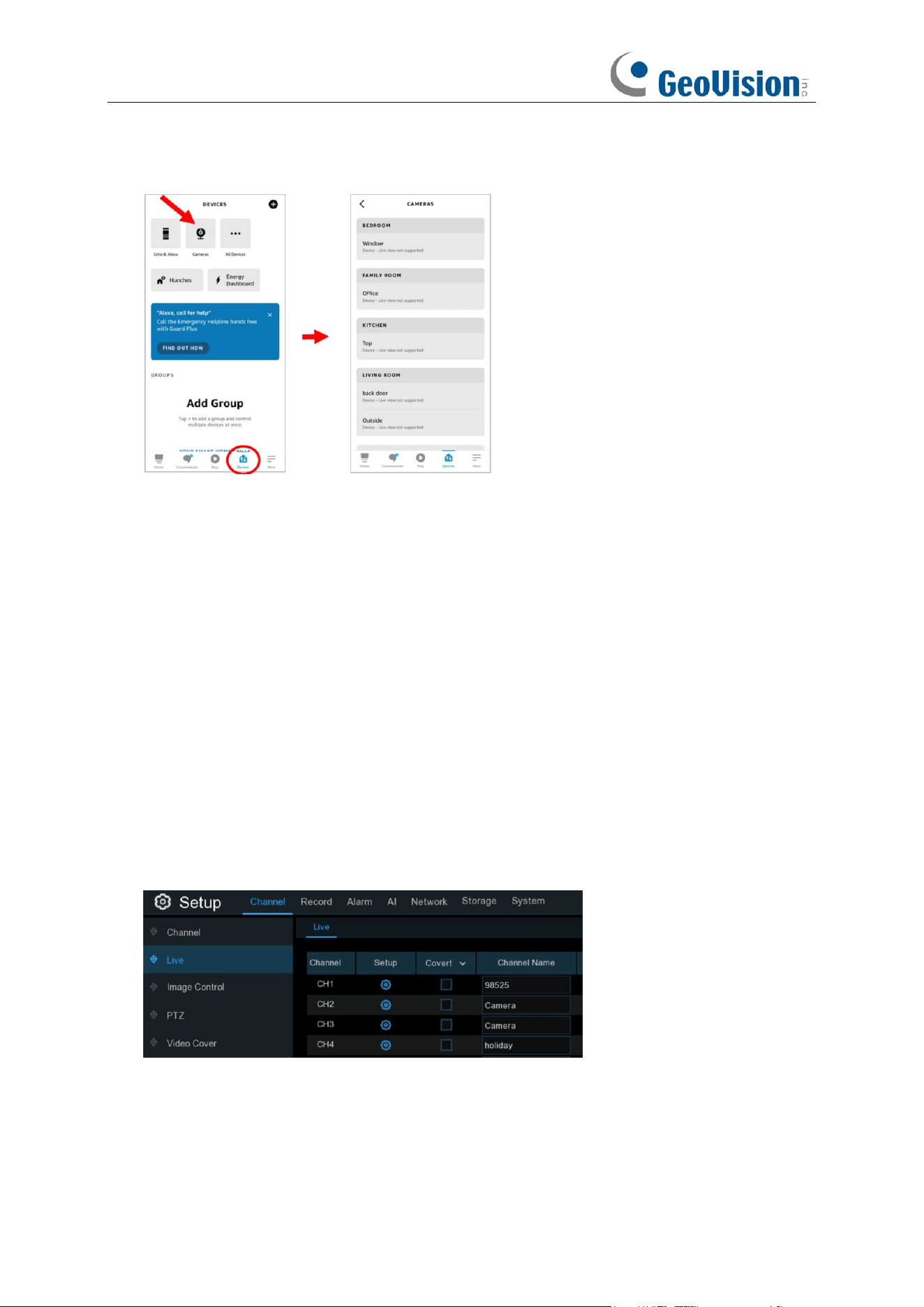
161
14. All added cameras will be listed in the Devices. Touch the “
Cameras
” icon to check all added
cameras.
15. Press and hold on the voice button on the remote controller of the fire TV stick, and speak the
command clearly. The command could be like: Show the XXX camera / Show XXX. XXX is
the camera channel name. For example, if the channel name is "Office", you could speak
"Show my office camera".
16. Wait for a while, you will see the real time images from the Office camera on your TV monitor.
17. If you want to quit the camera live view, speak "Stop".
18. If you have changed the channel name, you would need to discover and add the camera
again.
5.5.6.2 Voice Assistant with Google Chromecast
1. Input your Google account, and the click "Bind" button to connect to bind your Google
account. To choose the video stream you want to cast on your TV monitor.
2. Go to Channel – Live menu, and give a Channel Name which is easy to call to the channel(s)
you want to cast on your TV monitor.
3. Connect the Chromecast to your TV monitor, and power on it.
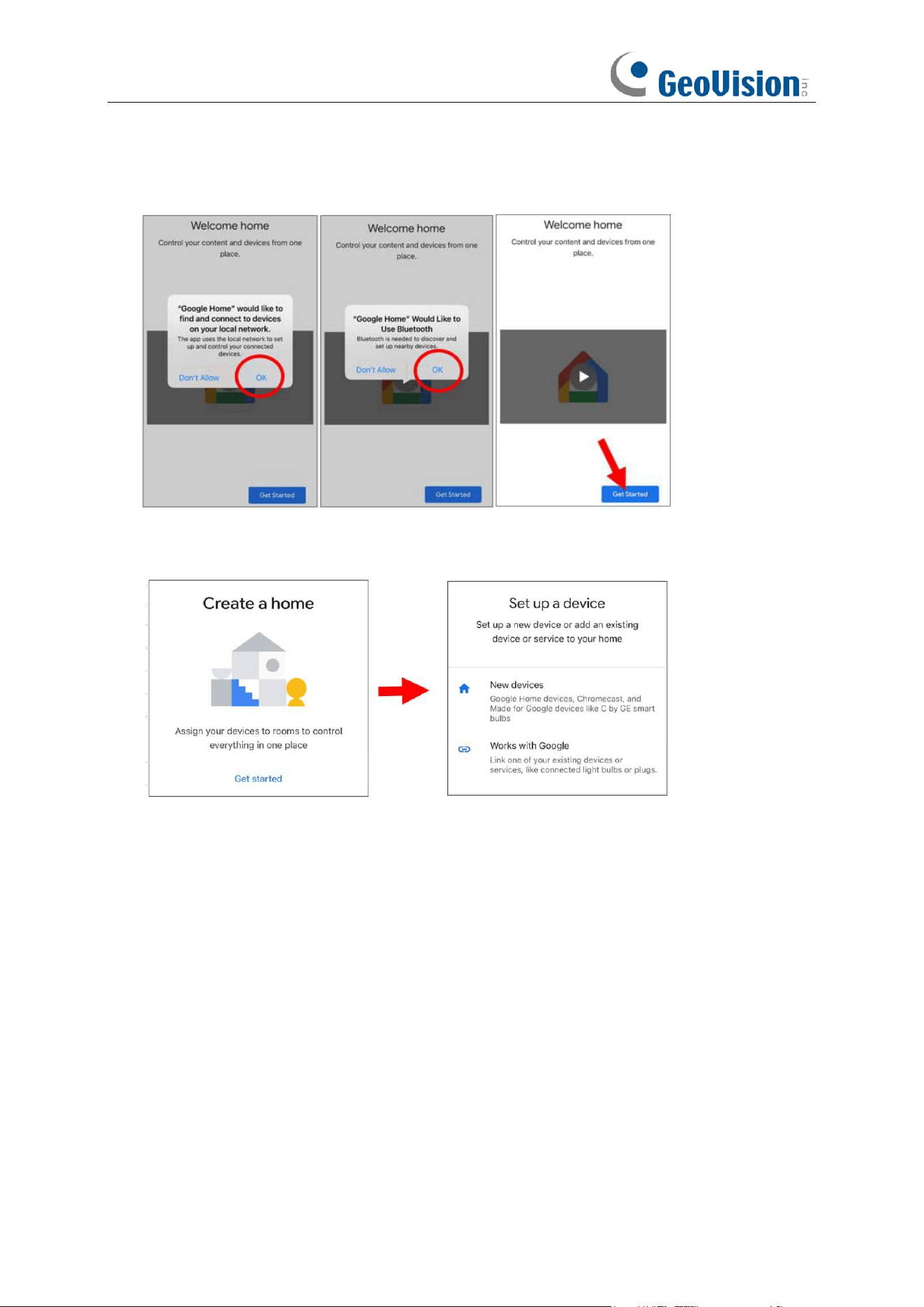
162
4. Search and install Google Home app to your mobile phone from app store. Run the installed
Google Home app, touch "OK" to allow the app to use your local network and Bluetooth and
then touch "Get Started".
5. To log in your Google account which is the same as the one you bind to the NVR.
6. Touch “Get Started” to create a home, and then touch “New devices.”
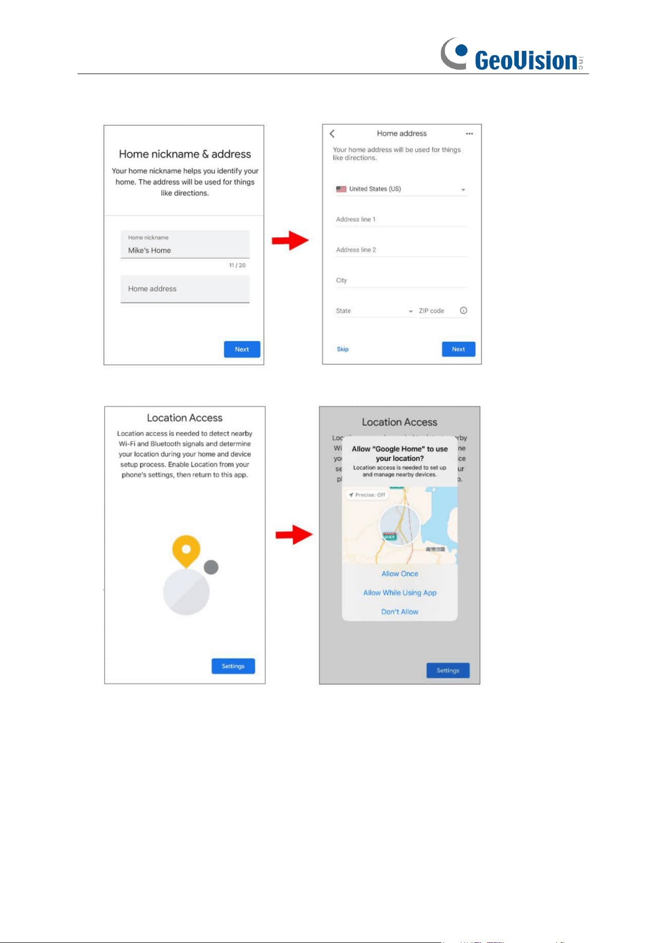
163
7. Input the Home nickname and address and then touch “Next”.
8. To allow location access for the app.
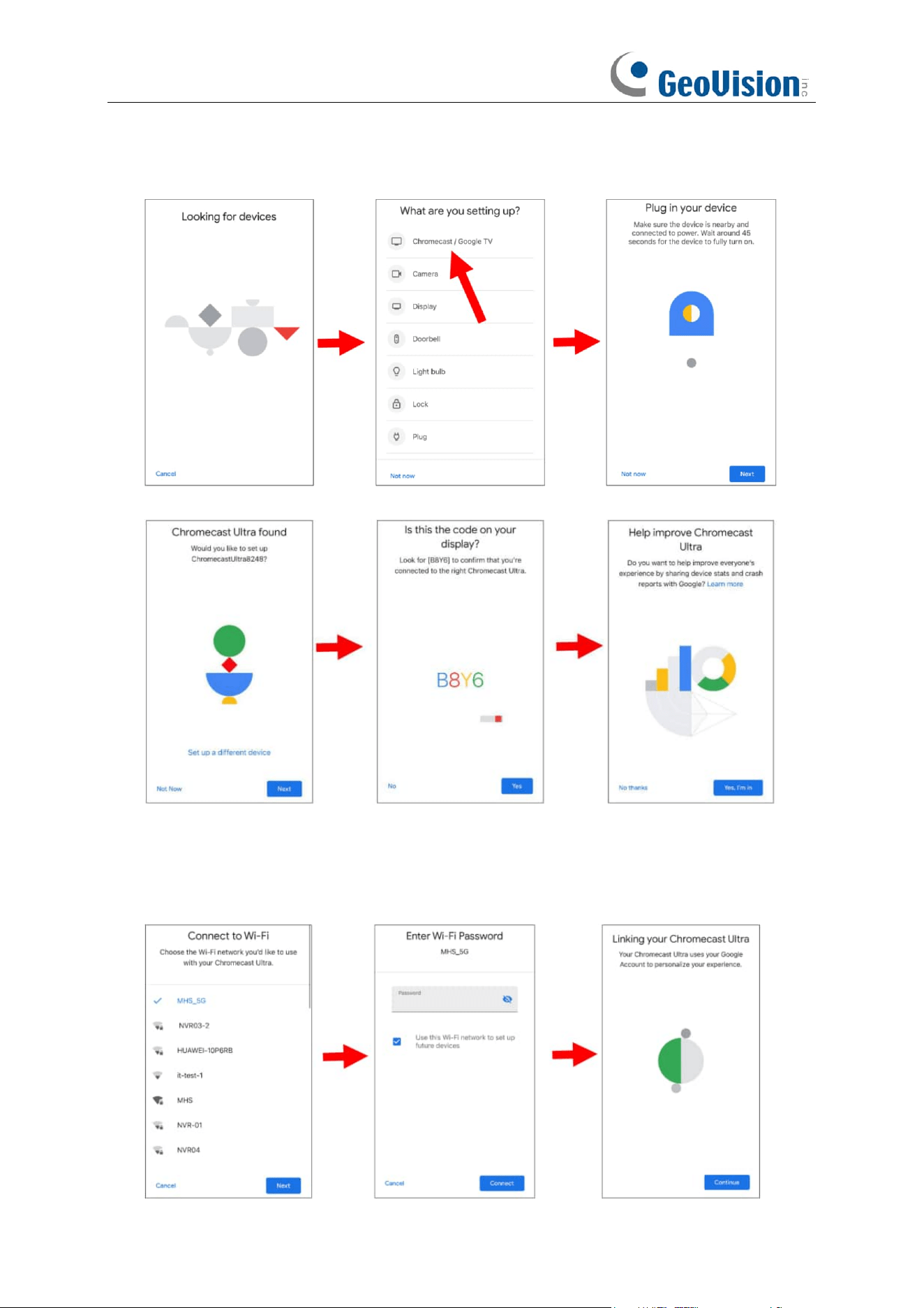
164
9. The app will automatically try to search devices from your local network. Choose Chromecast
/ Google TV. Make sure your Chromecast is turned on already, then touch "
Next
".
10. Your Chromecast will be found. Touch "
Next
" to connect. Confirm the code by touching "
Yes
".
11. Choose a location for your Chromecast, then touch "Next".
12. Choose the Wi-Fi network for your Chromecast and input the Wi-Fi password to connect.
Make sure the Wi-Fi you choose is the same one with your mobile phone and is in the same
local network with your NVR. Touch "Continue" to next step.
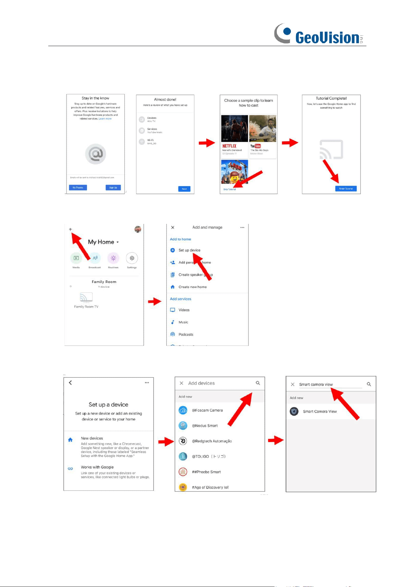
165
13. Touch "No Thanks", or "Sign Up" to login your google account. Touch "Next" and "Skip
Tutorial", and then touch "Finish Tutorial".
14. Now the Chromecast has been added to your Google Home. Touch the + icon on the left top
corner. Indoor, then choose “Set up device”.
15. Choose “Work with Google”, touch the search icon on the right top corner and then input
“smart camera view”.
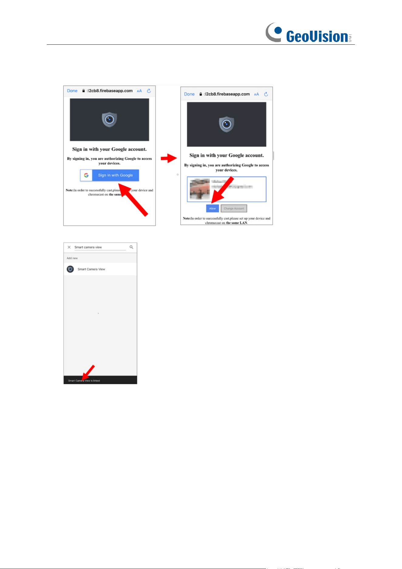
166
16. Touch on “Smart Camera View” in the search result. You would need to sign in your Google
account and allow Google to access your device.
17. Wait for a while, the Smart Camera View application will be linked to Google Home.
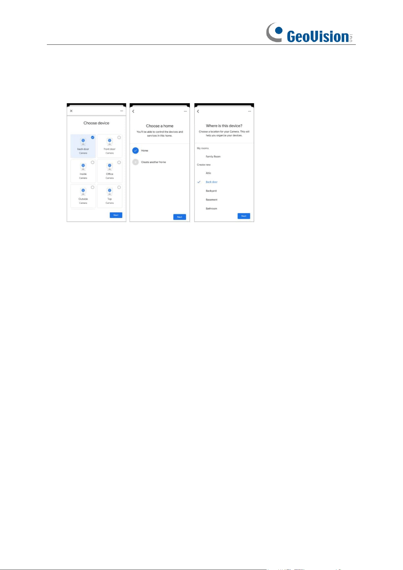
167
18. Now the available cameras in your NVR will be displayed. Choose one of the cameras and
then touch "Next" button. Choose a home & location for the cameras step by step. Repeat
this step to add all cameras.
19. Search and install Google Assistant app to your mobile phone from app store.
20. Run the Google Assistant, login your google account which is same as the one you bind to the
NVR.
21. Now, you're able to stream your camera to your TV monitor by using text or voice command,
like "Show/play the *** Camera on XXX TV", in which *** is the channel name of the camera,
XXX is your TV's name.
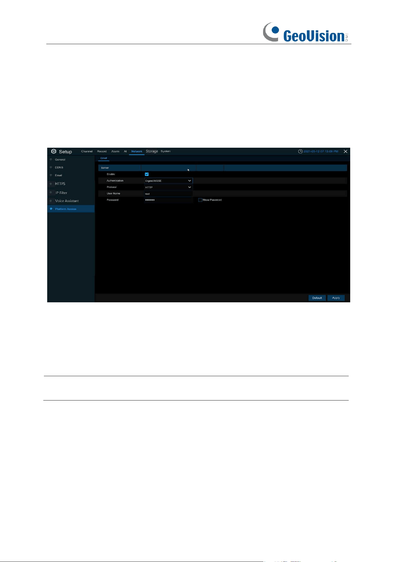
168
5.5.7 Platform Access
5.5.7.1 Onvif
Enable this function to allow devices to be searched and added by other third-party platforms
through the ONVIF protocol.
Enable: Enable switch. If turn off this menu, the service will be failed.
Authentication: Login authentication mode, authentication methods including Digest_sha256,
Digest, Digest/WSSE, and WSSE.
Protocol: Connection protocol
Username: Login user name
Password: Login user password
Note:
The stream connected by the back end through the ONVIF protocol are all the pictures of
the first channel.
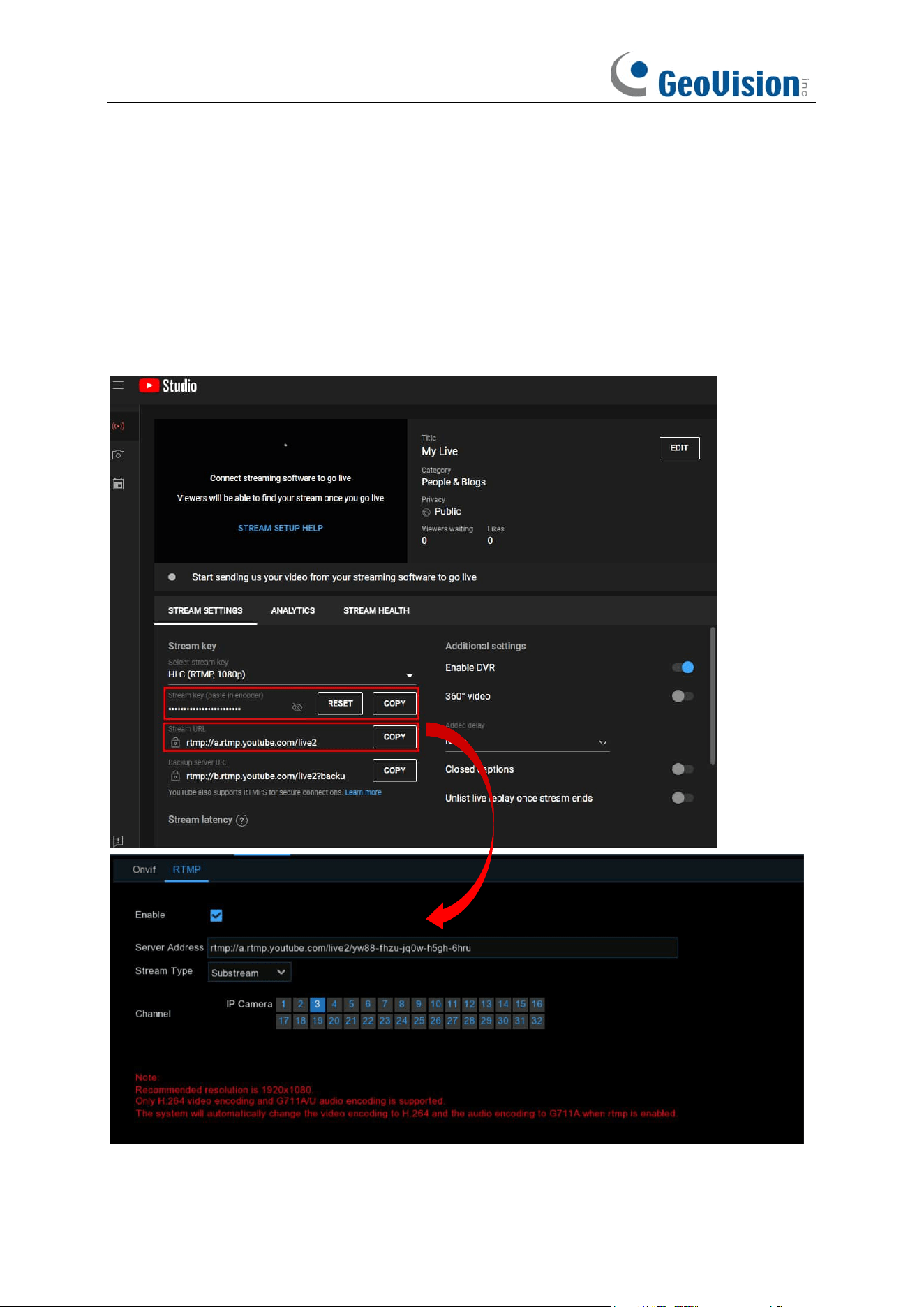
169
5.5.7.2 RTMP
The audio and video streams of the NVR channels can be pushed to the YouTube website by
RTMP for live broadcasting. To use this function, you need to do the following: Register a YouTube
account, create a live streaming studio, set the URL and live code of the live streaming studio, set
the live server address bar for the device, and enable and configure the code stream type and live
broadcasting channels. After saving the configuration, you can go to the YouTube live room to
refresh the page to watch live broadcasting.
Enable: Used to set whether to enable the RTMP live broadcasting function.
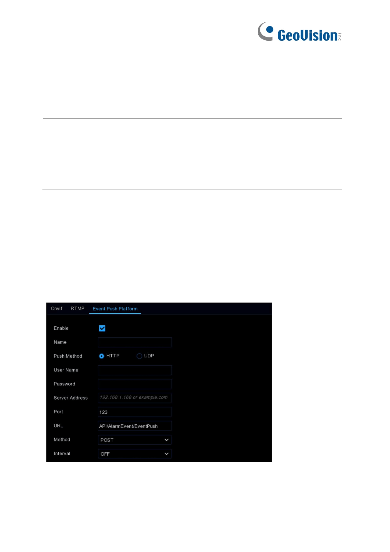
170
Server Address: Enter the live broadcasting address and live code of the YouTube server. (Note:
"/" is used between the live broadcasting address and live code of the YouTube server.)
Stream Type: Select the stream type of the live broadcasting channel. Both main stream and
substream are supported.
Channel: Select the channel for live broadcasting. Only one channel can be selected.
Note:
1. To ensure the live broadcasting effect, it is recommended that the resolution of the stream
not exceed 1920 × 1080.
2. Live broadcasting can be conducted for only the data streams of H.264 video encoding
format and G711A/U audio encoding format.
3. A YouTube live code can be set for only one device and cannot be reused.
5.5.7.3 Event Push Platform
It is used to push the alarm information from the device to the specified third-party platform (the
use of this function is required to ensure that the third-party platform has completed the docking
debugging with the device).
Event push is divided into HTTP push and UDP push: HTTP has POST and GET methods; UDP
has unicast, multicast and broadcast methods.
HTTP push
Enable: Enable or disable the event push function.
Name: Set the name of the device to be used for sending alert messages to the third-party
platform.
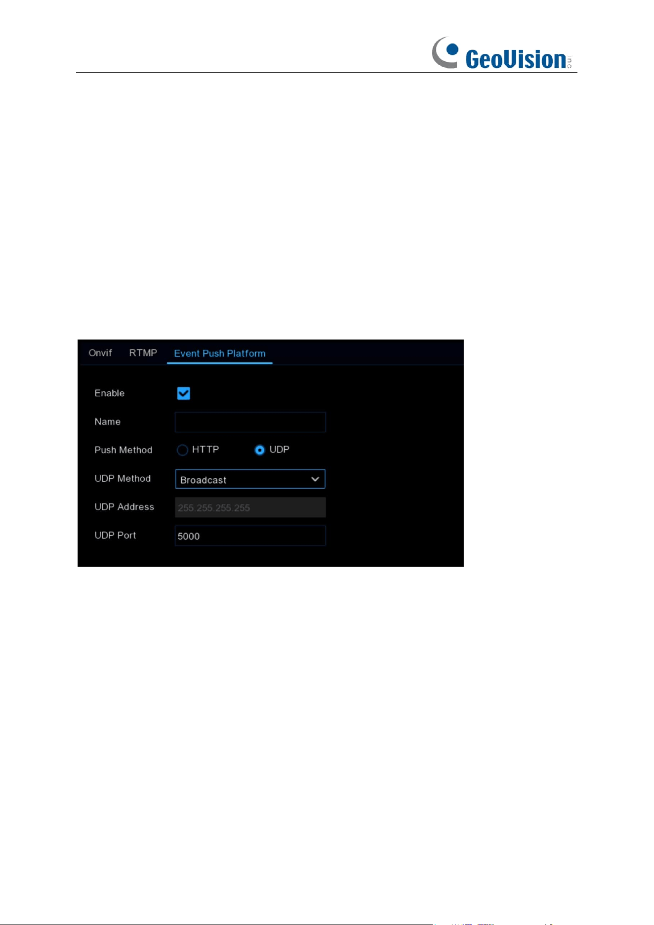
171
Push Method: Support HTTP push method and UDP push method, check HTTP for HTTP push
method, check UDP for UDP push method.
User Name: User name of the third-party platform
Password: Password of the third-party platform
Server Address: Address of the third-party platform
Port: Third-party platform server port (port range 1-65535).
URL: Third-party platform server API interface.
Method: HTTP push type. Support POST method and GET method: only HTTTP-POST method
supports push map, others are just push message without accompanying push map; the alarm
type of push map is consistent with the preview alarm bar on web side.
Interval: Interval of keepalive, according to the set time, the device will send messages to the
server regularly, UDP has no keepalive mechanism.
UDP push
Enable: Enable or disable the event push function.
Name: Set the name of the device used to send alert messages to the third-party platform.
Push Method: Support HTTP push method and UDP push method. If HTTP is checked, it is HTTP
push method, if UDP is checked, it is UDP push method.
UDP Method: Support Unicast, Multicast and Broadcast:
Unicast: Enter the IP address and port of the client's UDP server to receive push messages, and
only this address can receive messages.
Multicast: Multiple client UDP servers on the same network segment with the same UDP address
and port can receive the message, and other non-UDP addresses will not receive the message.
Broadcast: All UDP servers on the same network segment can receive the message.
UDP Address: UDP server address.
UDP Port: UDP server port (port range 1-65535).
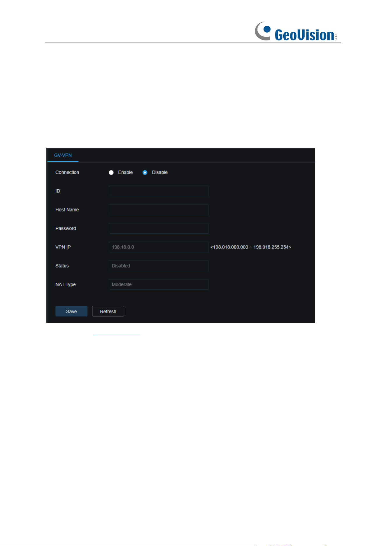
172
5.5.8 GV-VPN
GV-VPN is an application empowered by P2P VPN technology and the cloud-based platform,
GV-Cloud. By applying GV-VPN, users are allowed to create a virtual private network environment
enclosed for multiple NVRs. It saves the trouble of separate router configurations and links the
NVRs to the same virtual private network. Note that this is only applicable to GV-RNVRL810-P /
GV-RNVR3240-N.
For details, see GV-VPN Guide.
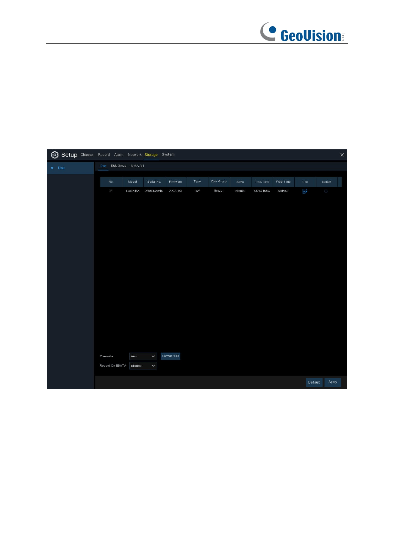
173
5.6 Storage
In this section, you can configure the internal HDD function.
5.6.1 Disk
This menu allows you to check & configure the internal HDD(s). You need to format the HDD only
at the first startup and if you replace a new HDD.
Format HDD
: Select the HDD you want to format and then click
Format HDD
. To start formatting,
you need to enter your user name and password and then click
OK
to confirm to continue
formatting.
Overwrite
: Use this option to overwrite the old recordings on the HDD when the HDD is full. For
example, if you choose the option 7 days then only the last 7 days recordings are kept on the HDD.
To prevent overwriting any old recordings, select
OFF
. If you have disabled this function, check
the HDD status regularly, to make sure the HDD is not full. Recording will be stopped if HDD is full.
Record on ESATA
: This menu only displayed when your NVR is coming with an e-SATA port on
the rear panel. It will allow to record the video to external e-SATA HDD to enhance your HDD
capacity. If the e-SATA recording function is enabled, e-SATA backup function will be disabled.
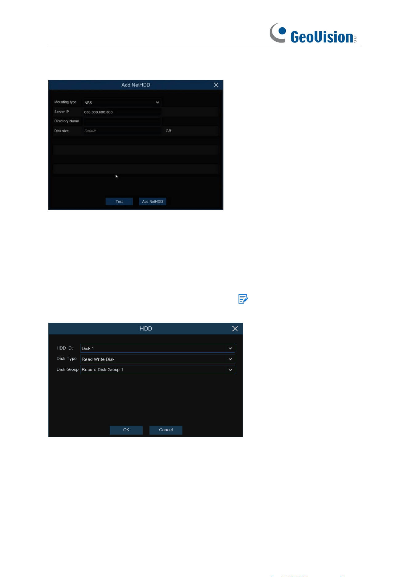
174
Add NetHDD: To add your NAS disk.
Mounting Type: To choose the mounting type from NFS and SMB/CIFS. You would need to input
the account name and password of NAS if you choose SMB/CIFS.
Server IP: IP the IP address of NAS storage.
Directory Name: Input the directory name on which you want to save your recording data.
Disk Size: To set the capacity size of the NAS storage.
Test: Click to test the connection of NAS storage.
Add NAS HDD: Click to add NAS storage.
If your NVR supports to install multiple HDDs, the edit icon appears in your system, you can
click it to edit the HDD as below:
Disk Type:
Read-write, read-only, and redundant.
Read-write mode is the normal status for a HDD to save recording or search recording to play.
To prevent important video data from being overwritten during cyclic recording, the HDD can be
set as
Read-only
mode. New recording will be not able to save into this read-only HDD. You can
still search recording from this read-only HDD to play.
A
Redundant
HDD can be used to automatically backup video footage on the recording
(read-write) hard drive. When a redundant HDD is set, the system can be set to record cameras in
parallel to both the recording hard drive and the redundant hard drive in case of hard drive failure.
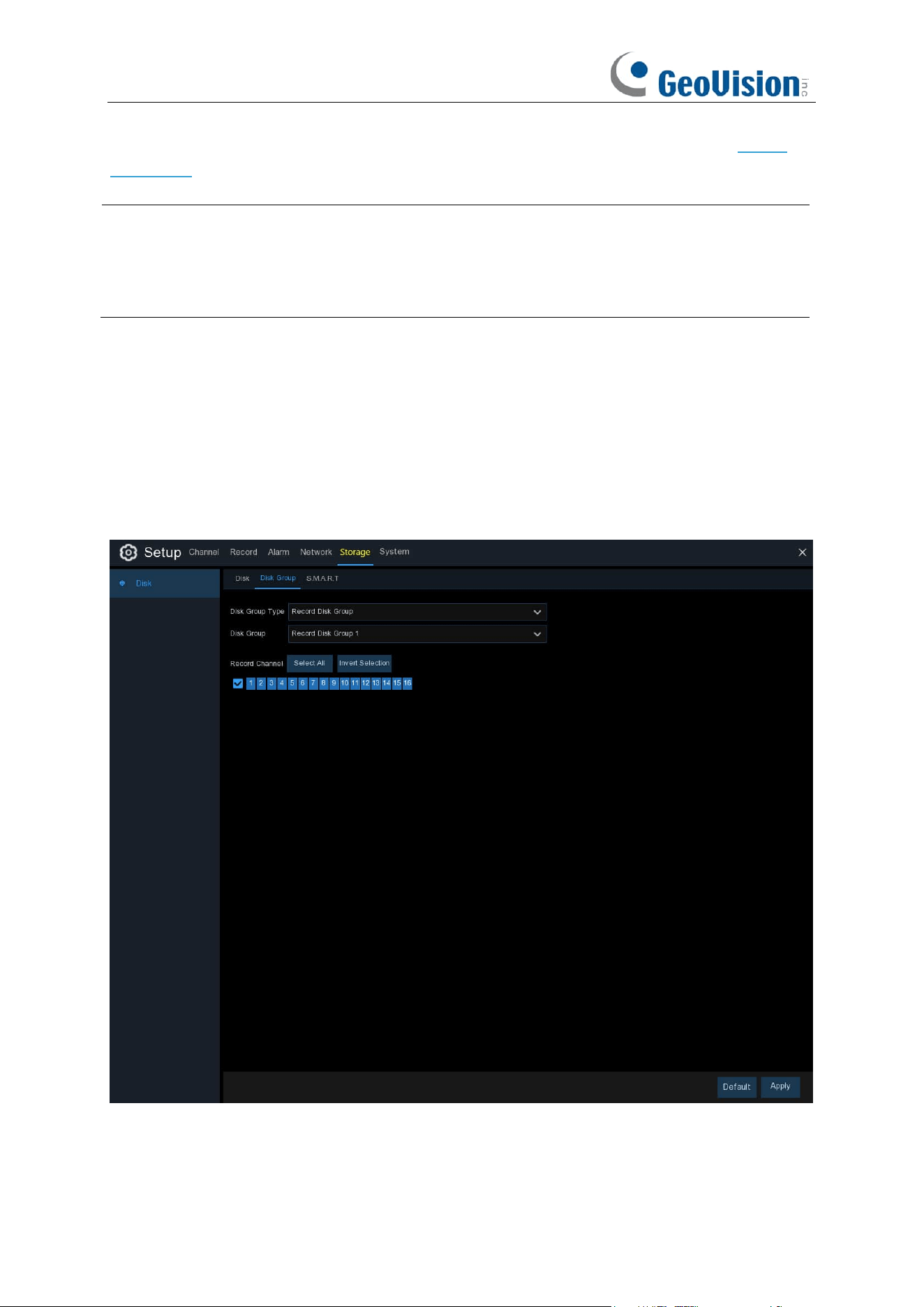
175
Disk Group: You can set the disks into different disk group for recording. See more on 5.6.1.1
Disk Group.
Note:
1. Redundant disk supports to save mainstream recording only.
2. If the disk type has been changed, the hard disks might be unmounted and offline. Please
wait a while till the hard disks mounted again.
5.6.1.1 Disk Group
If your NVR supports to install multiple HDDs, you can configure the HDD to be different groups.
HDD groups allow you to balance recordings across multiple hard drives. For example, you can
record channels 1~4 to one hard drive and 5~8 to a second hard drive. This can reduce the
amount of wear on the hard drives and may extend the life of the hard drives.
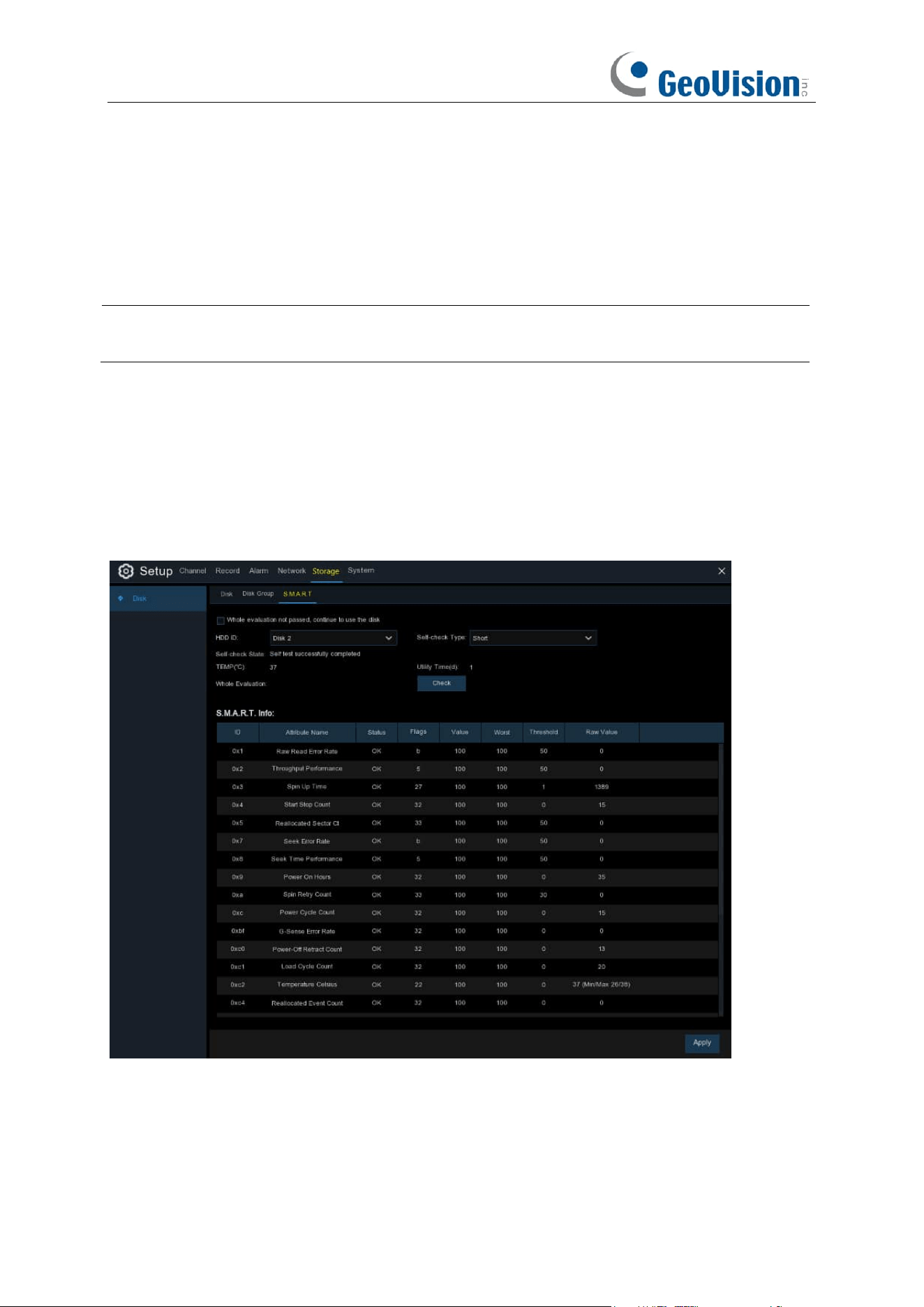
176
1. Use the dropdown next to
Disk Group Type
to select the type of group to configure.
2. Use the dropdown next to
Disk Group
to select the specific group within the selected group
type.
3. Click the numbered boxes representing channels to record channels to HDDs in the selected
group.
4. Click
Apply
to save.
Note:
There will be a prompt for models with more than 32 channels. It is recommended that the
video channel configuration of a single disk group should not exceed 32 channels.
5.6.1.2 S.M.A.R.T
This function can be used to display technical information on the hard drive installed inside your
NVR. You can also perform a test (there are three types available) to evaluate and detect potential
drive errors.
Whole Evaluation not passed, continue to use the disk:
If for some reason the hard drive has
developed a fault (such as one or more bad sectors), you can instruct your NVR to continue saving
to the drive.
Self-check Type:
There are three types available:
177
Short:
This test verifies major components of the hard drive such as read/write heads, electronics
and internal memory.
Long:
This is a longer test that verifies the above as well as performing a surface scan to reveal
problematic areas (if any) and forces bad sector relocation
Conveyance:
This is a very quick test that verifies the mechanical parts of the hard drive are
working.
Note
: When performing a test, your NVR will continue to work as normal. If an HDD S.M.A.R.T
error found, the HDD can be continued to use, but there will be a risk to lose recording data. It is
recommended to replace a new HDD.
5.6.1.3 RAID
The RAID function has a high requirement on hard disk performance. To ensure long-term stable
operation and reliability of RAID, it is recommended that you use enterprise-class hard disks
(including brand, model, and capacity) for RAID creation and other configurations. If
surveillance-class or desktop-class hard disks are used, data security may be affected. The
company shall not be liable for the data loss or data damage caused thereby.
Note:
The RAID function is only applicable to GV-RNVR256G0-N.
5.6.1.3.1 Enabling RAID
Choose Main Menu > System > General to open the general setting page. Select Enable Raid to
enable the RAID function, and then save the configuration. The configuration will take effect after
the system is restarted.
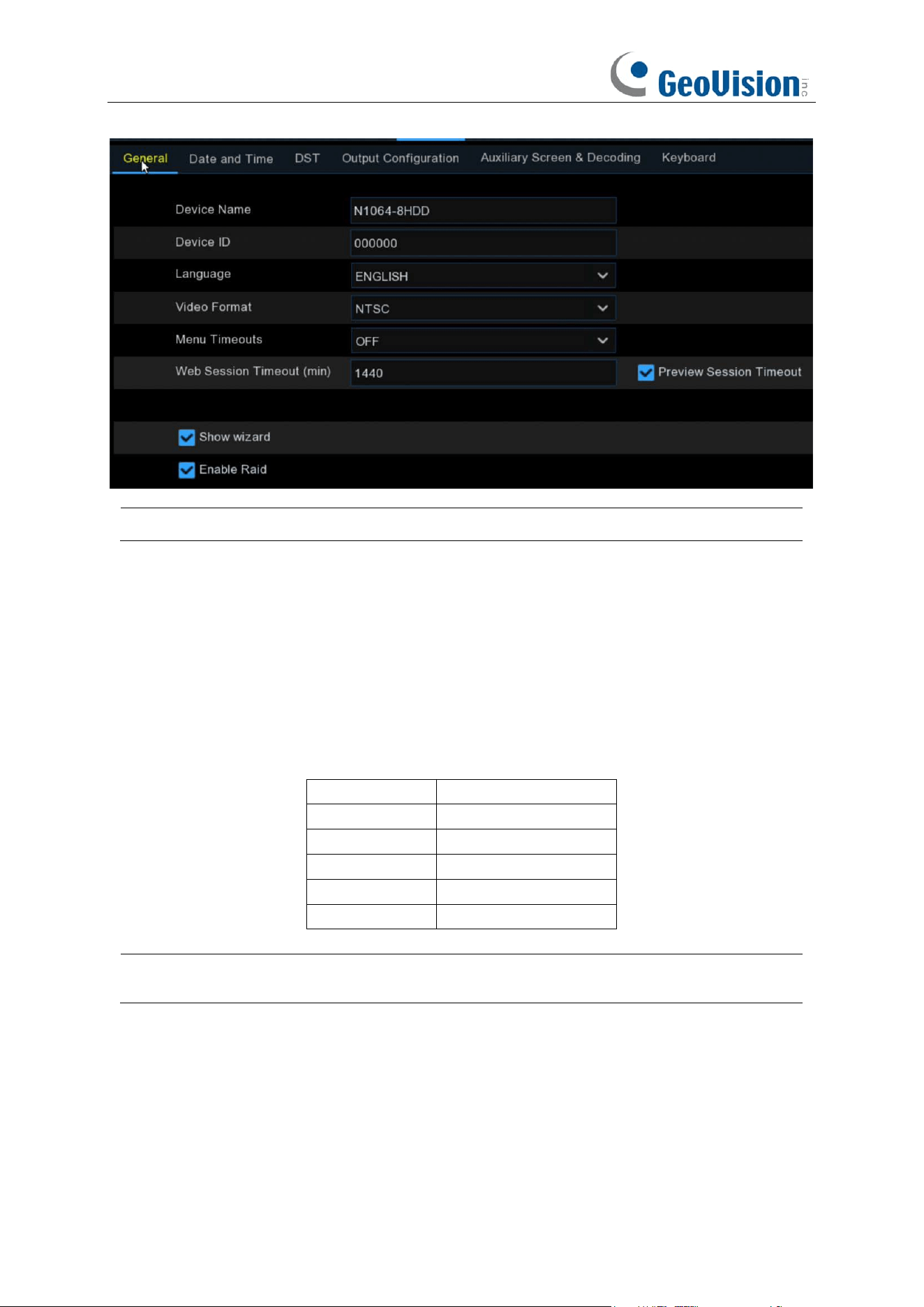
178
Note: After the RAID function is enabled, the NVR does not support E-SATA and NAS.
5.6.1.3.2 Creating RAID
You can create RAID either in one click or manually. For one-click creation, RAID5 is created by
default. For manual creation, RAID0, RAID1, RAID5, RAID6, and RAID10 are supported. You can
create different types of RAID in accordance with the actual number of hard disks to be accessed.
Hard Disk Quantity for RAID Creation
RAID Type
Hard Disk Quantity
RAID0
≥ 2
RAID1
2
RAID5
≥ 3
RAID6
≥ 4
RAID10
4 or 8
Note: The capacity of a single hard disk used for RAID creation is not less than 4 TB. For an
installed hard disk with a capacity less than 4 TB, it cannot be selected for RAID creation.
(1) Automatic RAID Creation
Through one-click configuration, the device can quickly create RAID and virtual disks. RAID5 is
created by default in one-click configuration, and at least four hard disks should be installed.
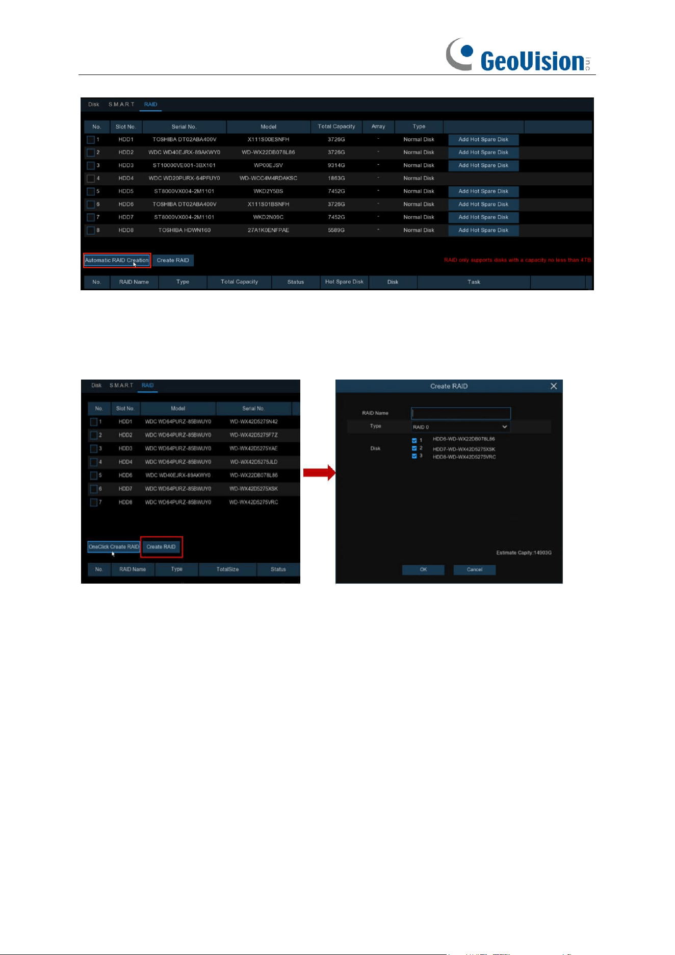
179
(2) Creating RAID Manually
To create RAID manually, click Create RAID to open the Create RAID page. Set the RAID name,
select the RAID type, select the hard disks, and click OK to create the RAID. After the RAID is
created, format the RAID.
To enable the RAID for normal use, you need to format the RAID first. After RAID formatting is
completed, open the disk group configuration page, select the disk group and recording channels,
and ensure that camera recording is normal.
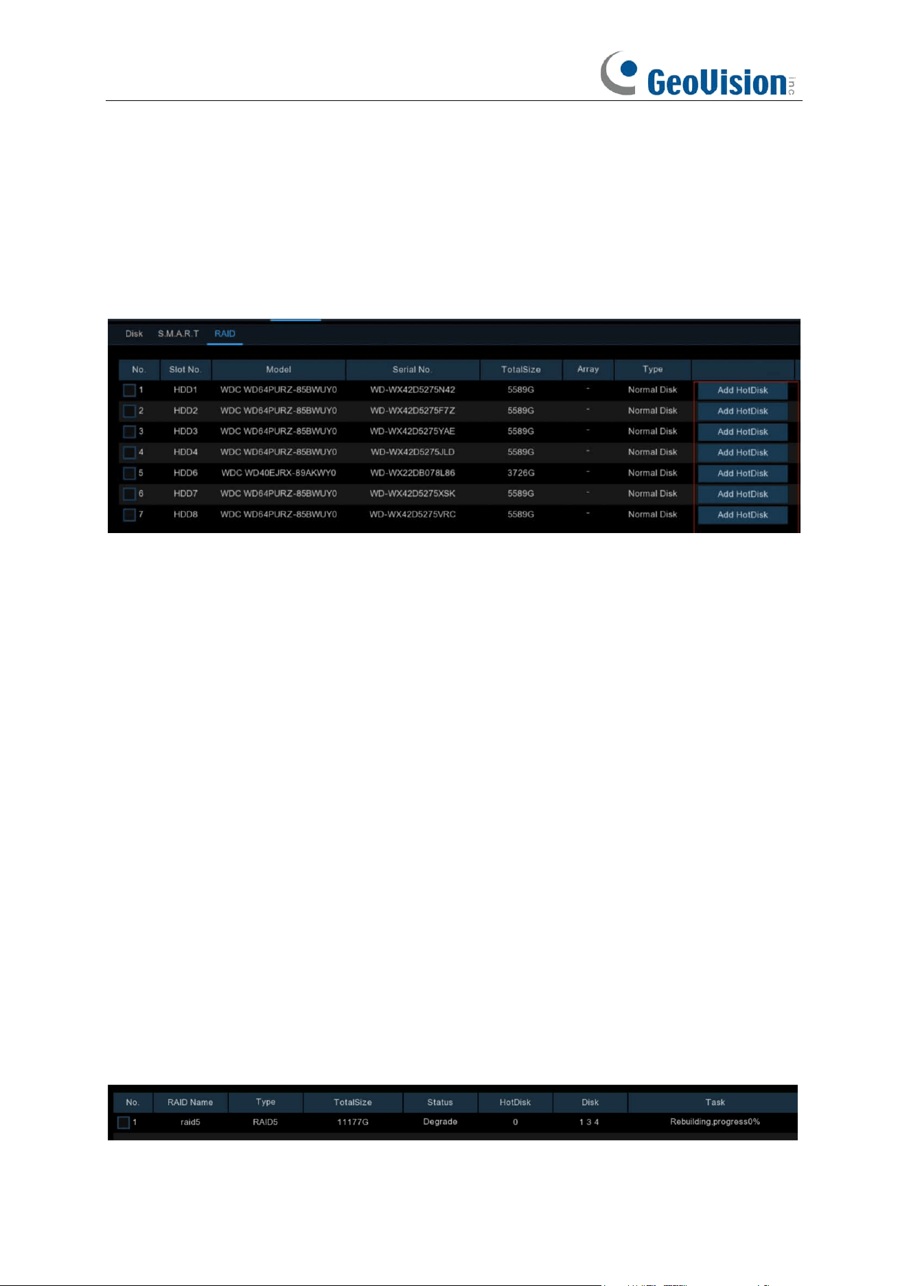
180
5.6.1.3.3 Setting Hot Spare Disks
To ensure RAID security, when RAID is in degraded status, the system can automatically carry out
RAID rebuilding. Therefore, it is recommended that hot spare disks be configured.
On the RAID configuration page, select an idle hard disk, click the Add HotDisk button, and
confirm the hot spare disk setting. (Hot spare disks are public disks and can be used by all created
RAIDs.)
5.6.1.3.4 Rebuilding RAID
The operational status of a RAID includes normal, degraded, and offline. To give full play to RAID
advantages and ensure the security and reliability of data storage, you can maintain the disks in a
timely manner by viewing RAID status. For a RAID, when there is no physical disk loss, the RAID
is in normal status; when the number of physical disks lost exceeds the threshold for the RAID
type, the RAID is in offline status; when the actual situation is between the two cases, the RAID is
in degraded status. When a RAID is in degraded status, it can be restored to normal status
through RAID rebuilding.
(1) Rebuilding RAID Automatically
Automatic RAID rebuilding requires that the device should be configured with hot spare disks in
advance and the hot spare disk capacity should be not less than the capacity of the smallest disk
of the RAID. If the above conditions are met, when a hard disk in a RAID is lost or damaged, the
hot spare disk is activated and considered as a candidate disk for the RAID, and then the
automatic rebuilding task is started.
For example, RAID5 consists of hard disks 1, 2, and 3, and hard disk 4 has been configured as a
hot spare disk. Hard disk 2 fails in operation, and the system does not detect it. Therefore, RAID5
is in degraded status, and hard disk 4 is immediately activated and considered as a candidate disk.
Then, the rebuilding process is started.
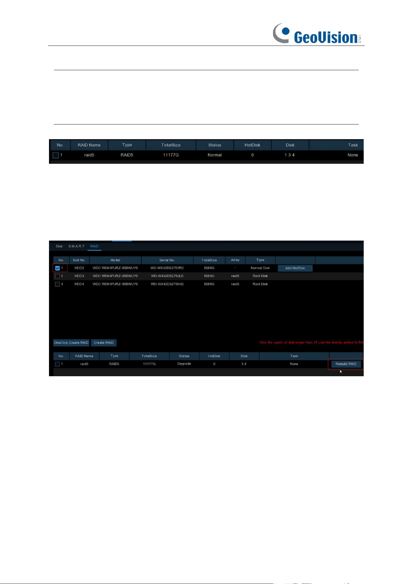
181
Note:
1. After rebuilding is completed, the RAID is restored to normal status.
2. After automatic rebuilding is completed, insert a normal hard disk and set it as a hot
spare disk to ensure that the automatic rebuilding process can be started normally the
next time an exception occurs.
(2) Rebuilding RAID Manually
When a RAID is in degraded status, if it has no hot spare disk, automatically rebuilding cannot be
implemented. You need to manually rebuild the RAID to restore it to normal status.
On the RAID configuration page, select an idle disk, and click the Rebuild RAID button, verify the
password, and then start RAID rebuilding. After the rebuilding is completed, the RAID is restored
to normal status.
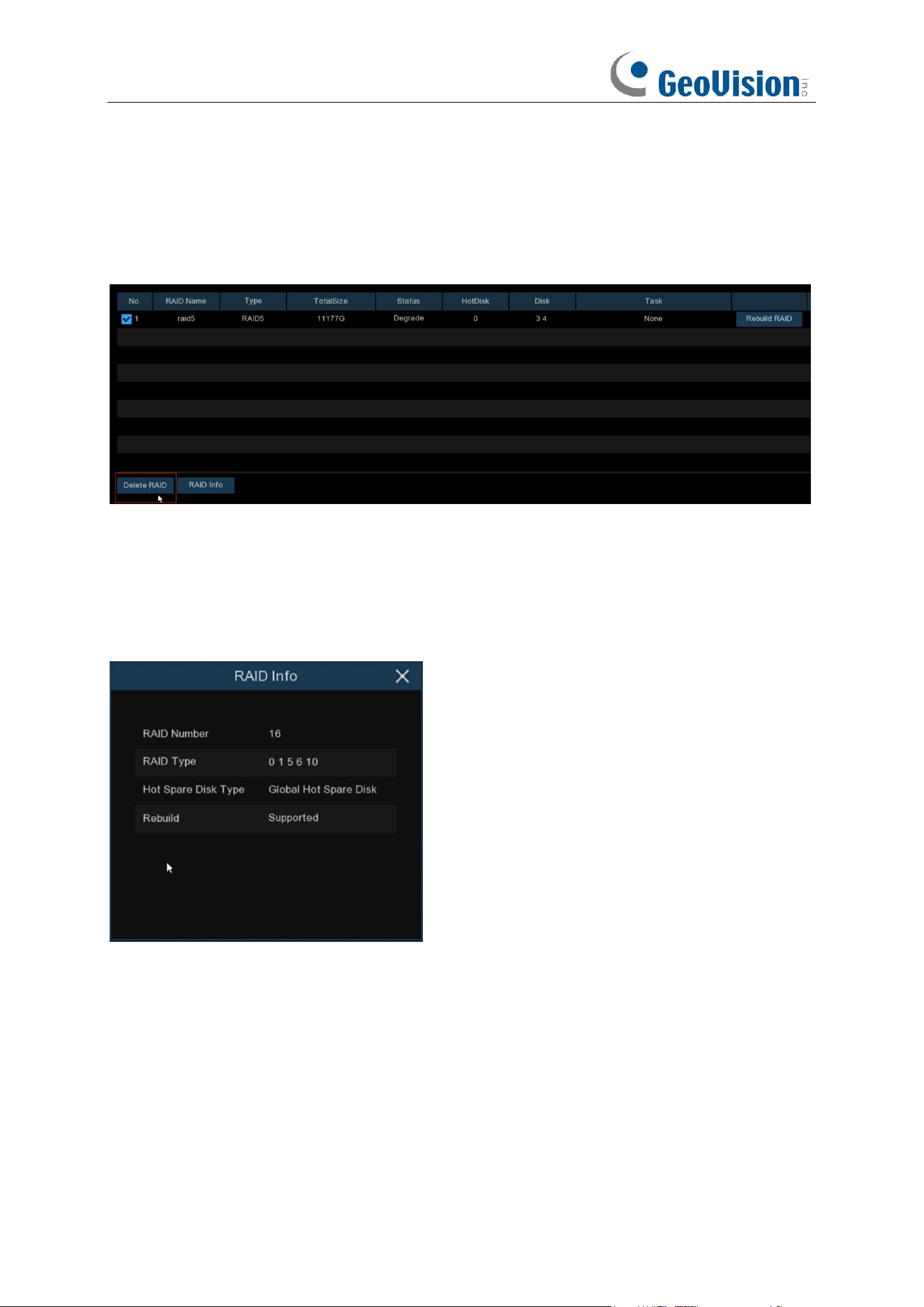
182
5.6.1.3.5 Deleting RAID
Select the RAID to be deleted, click the Delete RAID button, enter the administrator password,
and click OK to delete the RAID.
5.6.1.3.6 Viewing RAID Information
Click the RAID Info button to open the RAID Info page to view the RAID function information.
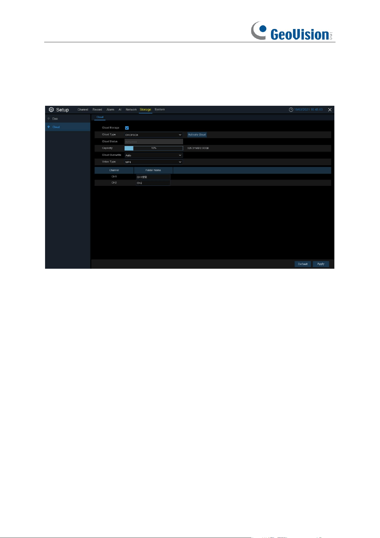
183
5.6.2 Cloud
Cloud function allows to upload pictures and videos to your cloud storage. It supports Dropbox and
Google Drive storage now.
Cloud Type: To choose Dropbox or Google Drive.
Cloud Status: This will change to Activated when active.
Capacity: When activated, this will display how much free space you have on your cloud storage.
Cloud Overwrite:
Use this option to overwrite the old recordings on the storage when it is full. For
example, if you choose the option 7 days then only the last 7 days recordings are kept on the
storage. To prevent overwriting any old recordings, select
OFF
. If you have disabled this function,
please check the cloud storage status regularly, to make sure the capacity is not full. Recording
will be stopped if the space is full.
Video Type: To choose the video format you want to upload.
Folder / Driver Name: To create a folder for each camera for saving its uploading files.
5.6.2.1 Dropbox Settings
1. Before activation, we recommend that you create a Dropbox account first. Go to
www.dropbox.com, input your name, email address, and password, agree to the terms &
conditions, then click or tap the sign up button. If you already have a Dropbox account, you
can skip this step.
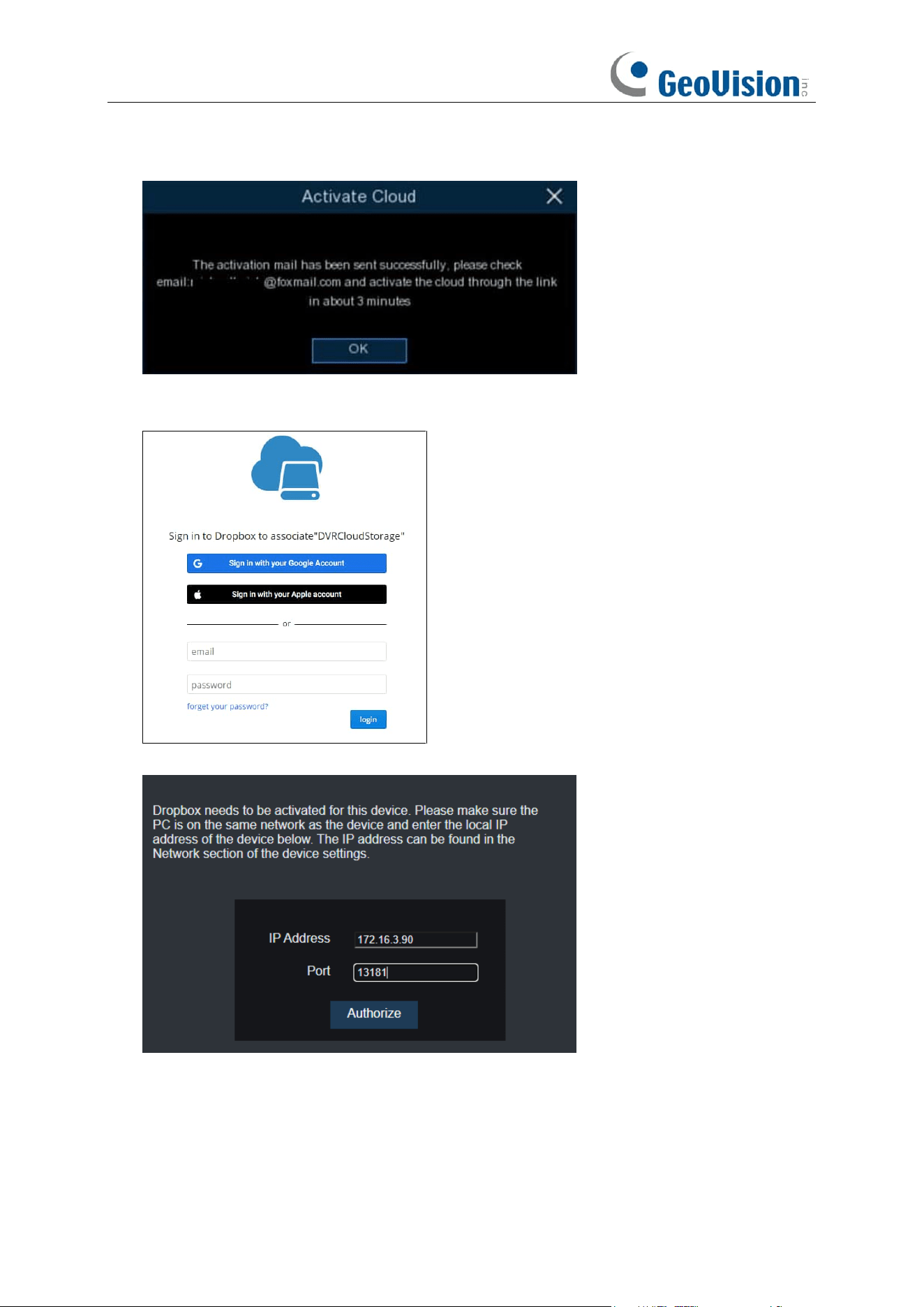
184
2. Click the Activate Cloud button, the system will send an activation letter to your receiver
email box which you have set in the Email Setup page.
3. Login your email box and click the link in the email content. It will turn to the cloud server
authorization login page. Input your Dropbox account name and password to login.
4. Input the NVR’s local IP address and web port, and then click Authorize.
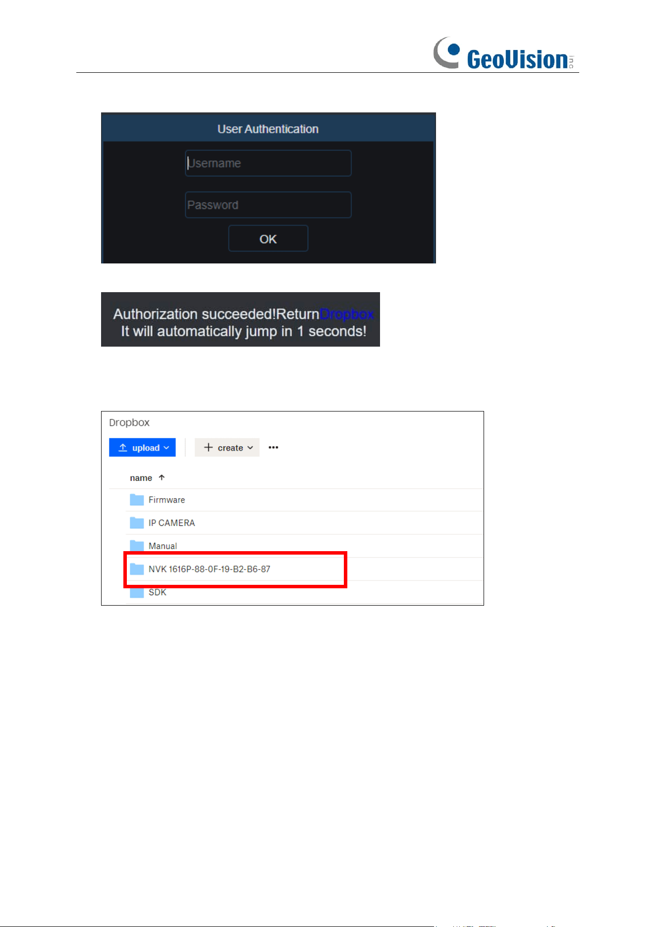
185
5. Input the NVR’s user name and password and then click OK.
6. Authorization finished; the webpage will turn to your Dropbox.
7. The Cloud has completed the setup if you find a new folder named by your NVR device name
and MAC address in the Dropbox storage. Your alarm pictures and videos will be uploaded to
this folder.
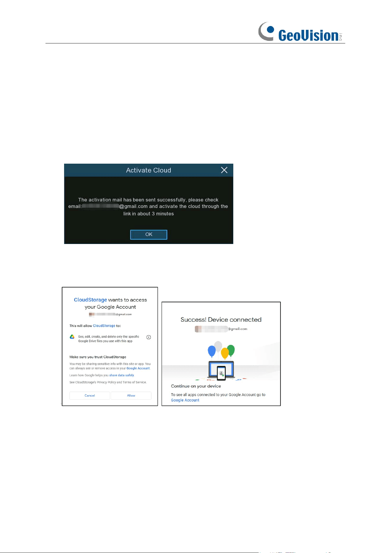
186
5.6.2.2 Google Drive Settings
1. Before activation, we recommend that you create a Google Drive account first. Go to
https://www.google.com/drive, input your name, email address, and password, agree to the
terms & conditions, then click or tap the sign up button. If you already have a Google Drive
account, you can skip this step.
2. Click the
Activate Cloud
button, the system will send an activation letter to your receiver
email box which you have set in the Email Setup page.
3. On the email, you will find an activation code and a link illustrated as below. Click the link and
then enter the activation code you received on the webpage, and then click Next.
4. Enter your Google account and password to login your Google Drive.
5. Click Allow, the settings of your Google Drive cloud have completed now.
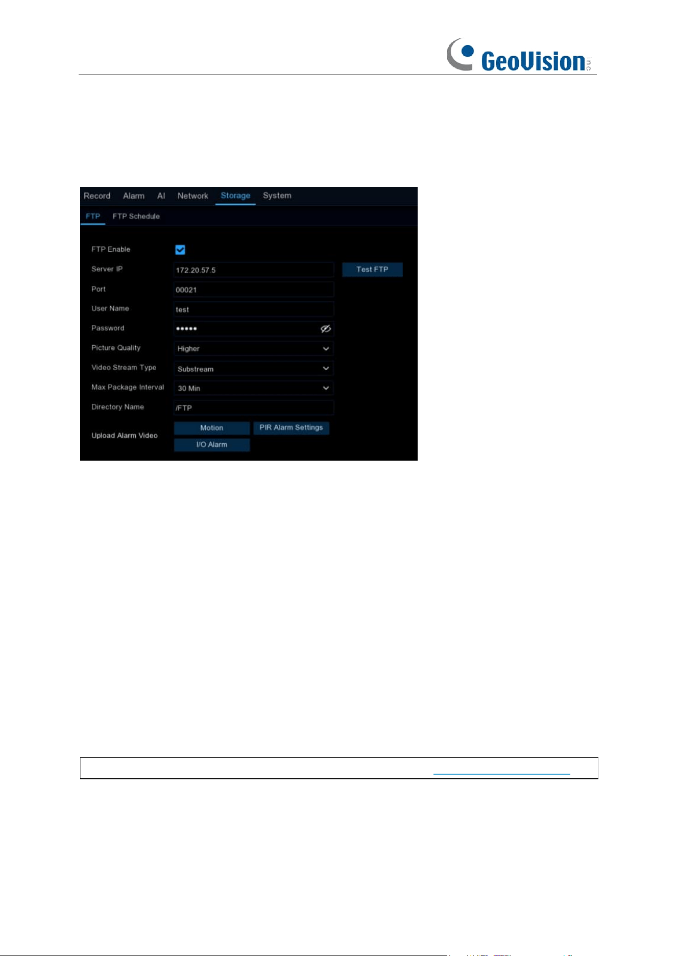
187
5.6.3 FTP
This menu allows you to enable FTP function to view and load captured snapshots from NVR to
your storage device over FTP.
FTP Enable
: Click to enable FTP function.
Server IP
: Enter your FTP server IP address or domain name.
Port
: Enter the FTP port for file exchanges.
Name/ Password
: Enter your FTP server user name and password.
Picture Resolution: To choose the resolution of snapshots that you want to upload. Maximum
resolution is 1920 x 1080.
Picture Quality: Choose the image quality of snapshots that you want to upload.
Video Stream Type: Choose mainstream or substream video you want to upload.
Max Package Interval: Set the maximum package interval, that is, what is the maximum
recording time of an event, if it exceeds this time, it will create another video file to continue
recording.
Directory Name
: Enter the default directory name for the FTP file exchanges.
Test FTP
: Click to test the FTP settings.
Upload Alarm Video:
Set the warning type for uploading video to FTP, click the option to enter the
warning menu in the corresponding alarm type.
Note:
To play videos uploaded to FTP server, make sure you use GV-R Series Video Player.
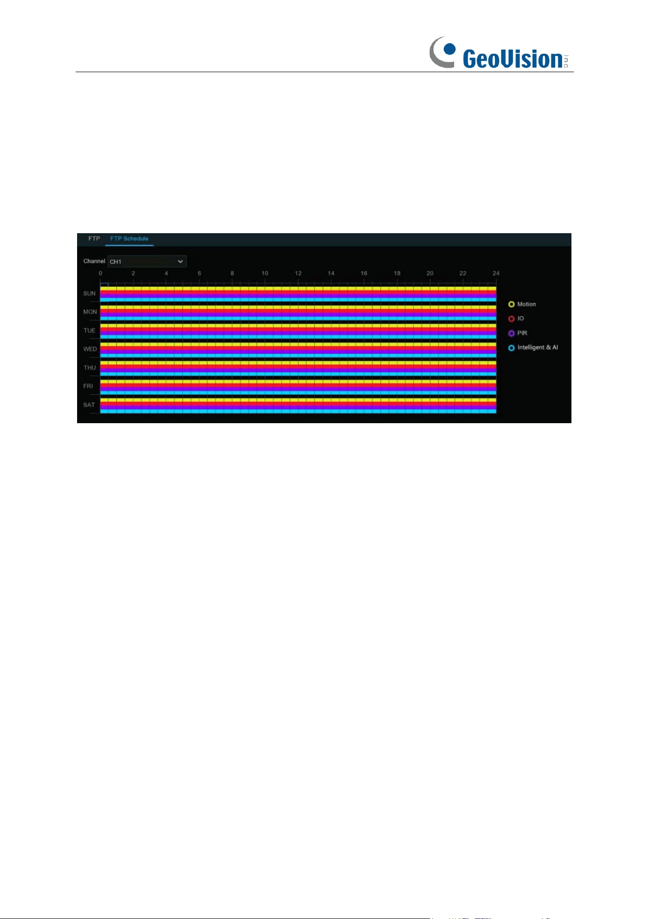
188
5.6.3.1 FTP Schedule
If FTP upload is enabled on your NVR, alarm images or videos would be uploaded 24 hours as
default. You can change the schedule when your NVR to upload the alarm images or videos. For
example, you may only want to receive alarm images or videos during the day but not in the
evening. An alternative schedule can be created for each camera.
1. Select a channel you want to set the schedule.
2. Click on ratio button of the alarm type that you want to upload for:
➔
Motion:
Upload for motion detection alarm images or videos
➔
IO:
Upload for I/O triggered alarm images or videos
➔
Intelligent & AI:
Upload for Intelligent or AI detection alarm images or videos
3. Using the mouse, click on a square to change or click and drag the mouse over the squares
corresponding to your desired period
4. Repeat step 2 & 3 to set the schedule for other alarm type.
5. The set schedule is valid only for one channel. If you want to use the same recording
schedule for other channels, use
Copy
function.
6. Click
Apply
to save your settings.
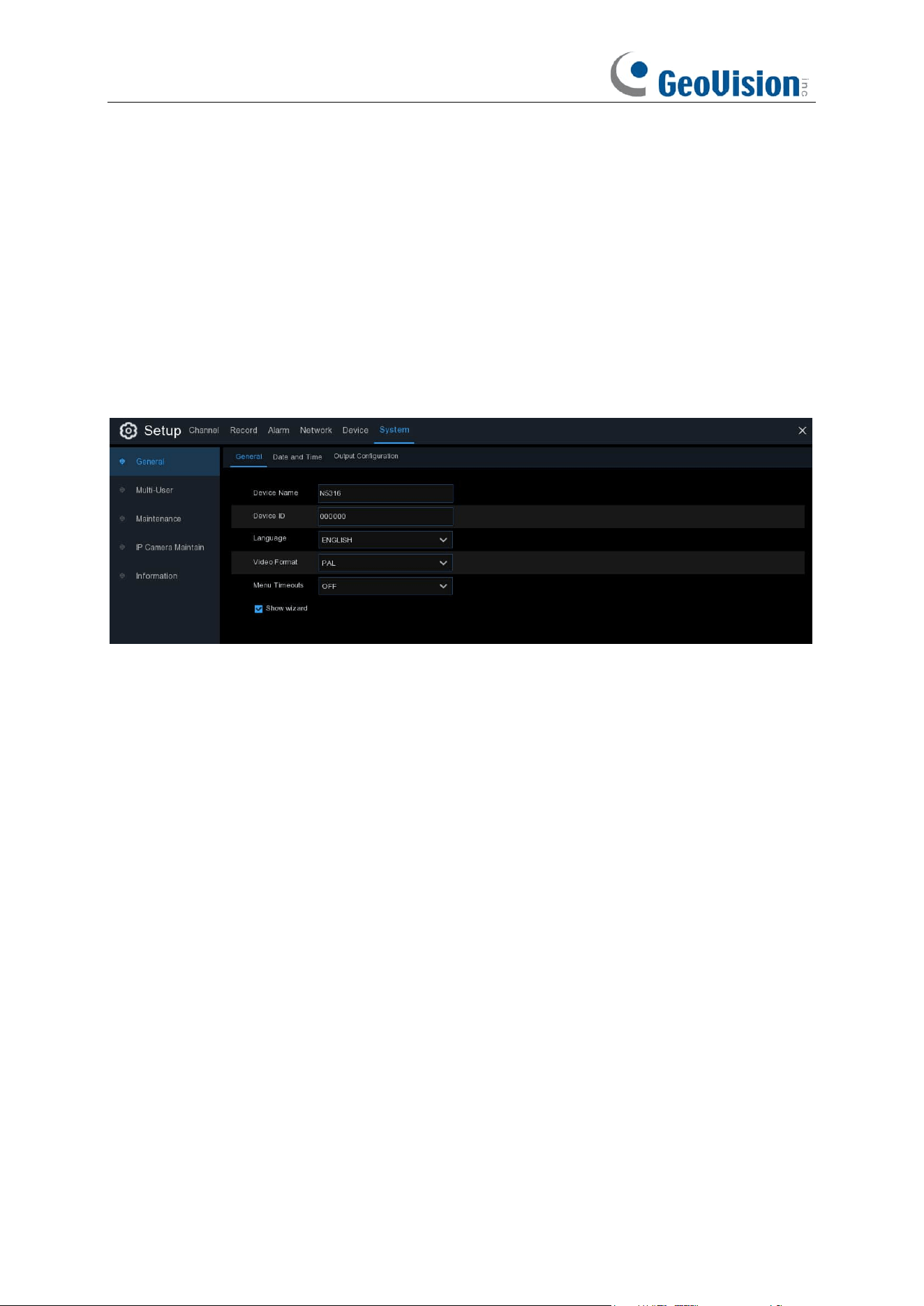
189
5.7 System
Change general system information such as date, time and region, edit passwords and
permissions, and more.
5.7.1 General
5.7.1.1 General
Device Name
: Enter the desired name for your NVR. The name can include both letters and
numbers.
Device ID
: Enter the desired ID for your NVR. The device ID is used to identify the NVR, and can
only be composed of numbers. For example, 2pcs NVRs are installed in the same place, the
Device ID is 000000 for one of the NVRs, and 111111 for another NVR. When you want to operate
the NVR with a remote controller, both NVRs may receive the signal from controller & act at the
same time. If you want to control only the NVR with ID 111111, you can input the Device ID 111111
in login page with remote controller for further operations.
Language
: Select a language you would like the system menus to be displayed in. Multiple
languages are available.
Video Format
: Select the correct video standard for your region.
Menu Timeouts / Idle Lock Time
: Click the drop-down menu to select the time your NVR will exit
the Main Menu when idle. This function is set to “OFF” by default (password protection will be
temporarily disabled).
Web Session Timeouts: Enter the time (in minutes) your NVR will exit web access when idle in
the setting page. Adjustable time can be set from 5 minutes to 1,440 minutes. If you tick on the
checkbox of "Preview Session Timeouts", the web access will be exited also when idle in the live
view page.
Show Wizard
: Click the checkbox if you would like to display the Startup Wizard each time you
turn on or reboot your NVR.
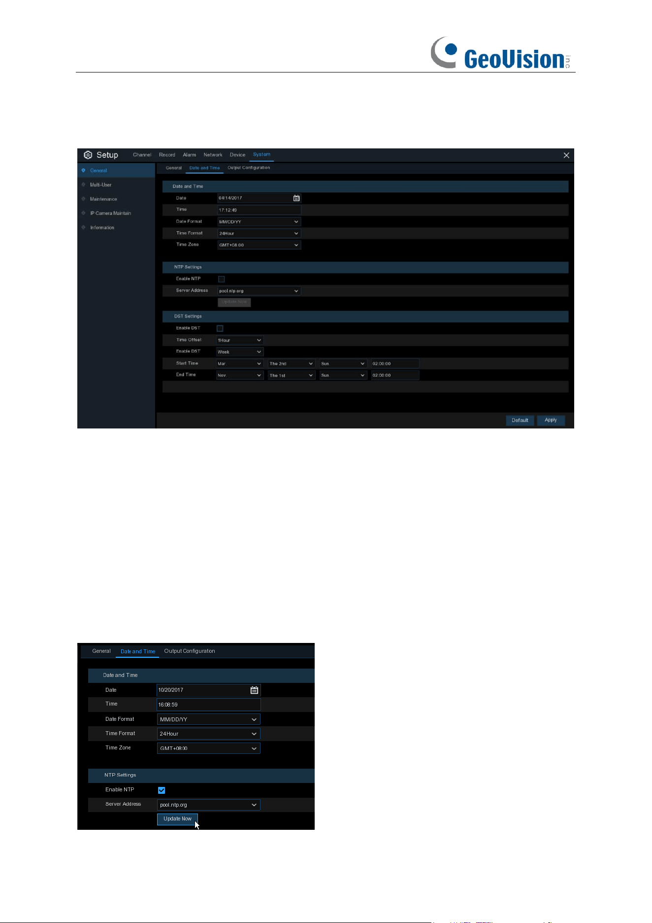
190
5.7.1.2 Date and Time
Date & Time
Date:
Click the calendar icon to change the date.
Time:
Click the dialogue box to change the time.
Date Format
: Select the preferred date format.
Time Format
: Select the preferred time format.
Time Zone
: Select a time zone relevant to your region or city.
NTP Settings
The NTP (Network Time Protocol) function allows your NVR to automatically sync its clock with a
time server. This gives it the ability to constantly have an accurate time setting (your NVR will
periodically sync automatically).
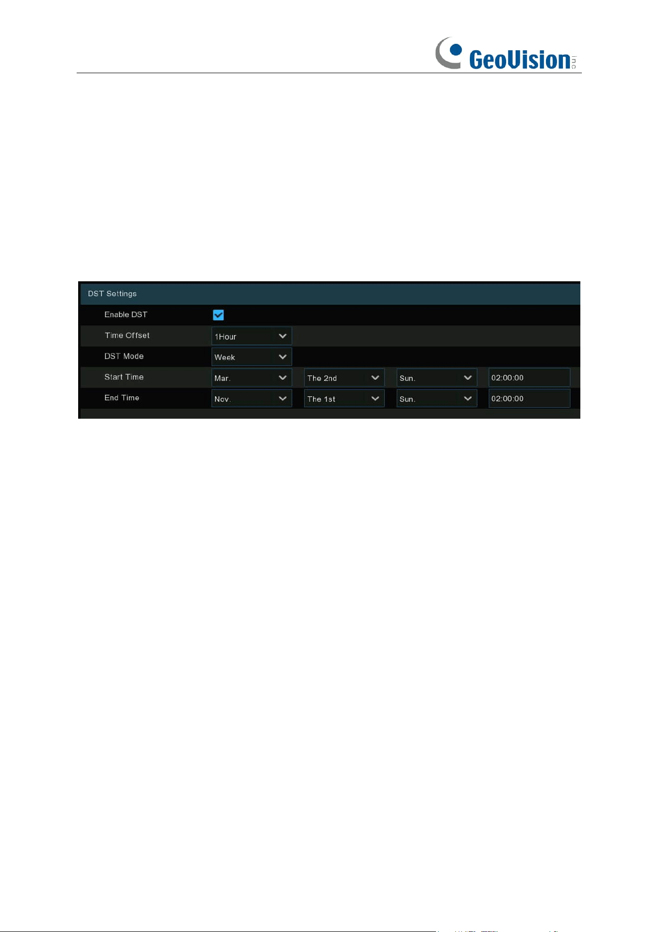
191
Tick the checkbox of "Enable NTP", and select a "Server Address", click "Update Now" to
manually sync the date & time. When NTP function is enabled, system will update the system time
at 00:07:50 per day or every time when the system is starting up. Click "Apply" to save your
settings.
5.7.1.3 DST Settings
The DST (Daylight Saving Time) function allows you to select the amount of time that Daylight
Saving has increased by in your particular time zone or region.
Enable DST
: If Daylight Saving applies to your time zone or region, check this option to enable.
Time Offset
: Select the amount of time that Daylight Saving has increased by in your time zone.
This refers to the difference in minutes, between Coordinated Universal Time (UTC) and the local
time.
Enable DST:
You can select how Daylight Saving starts and ends:
Week:
Select the month, a particular day and time when Daylight Saving starts and ends. For
example, 2 a.m. on the first Sunday of a particular month.
Date:
Select the start date (click the calendar icon), end date and time when Daylight Saving starts
and ends.
Start Time / End Time
: Set the start time and end time for Daylight Saving.
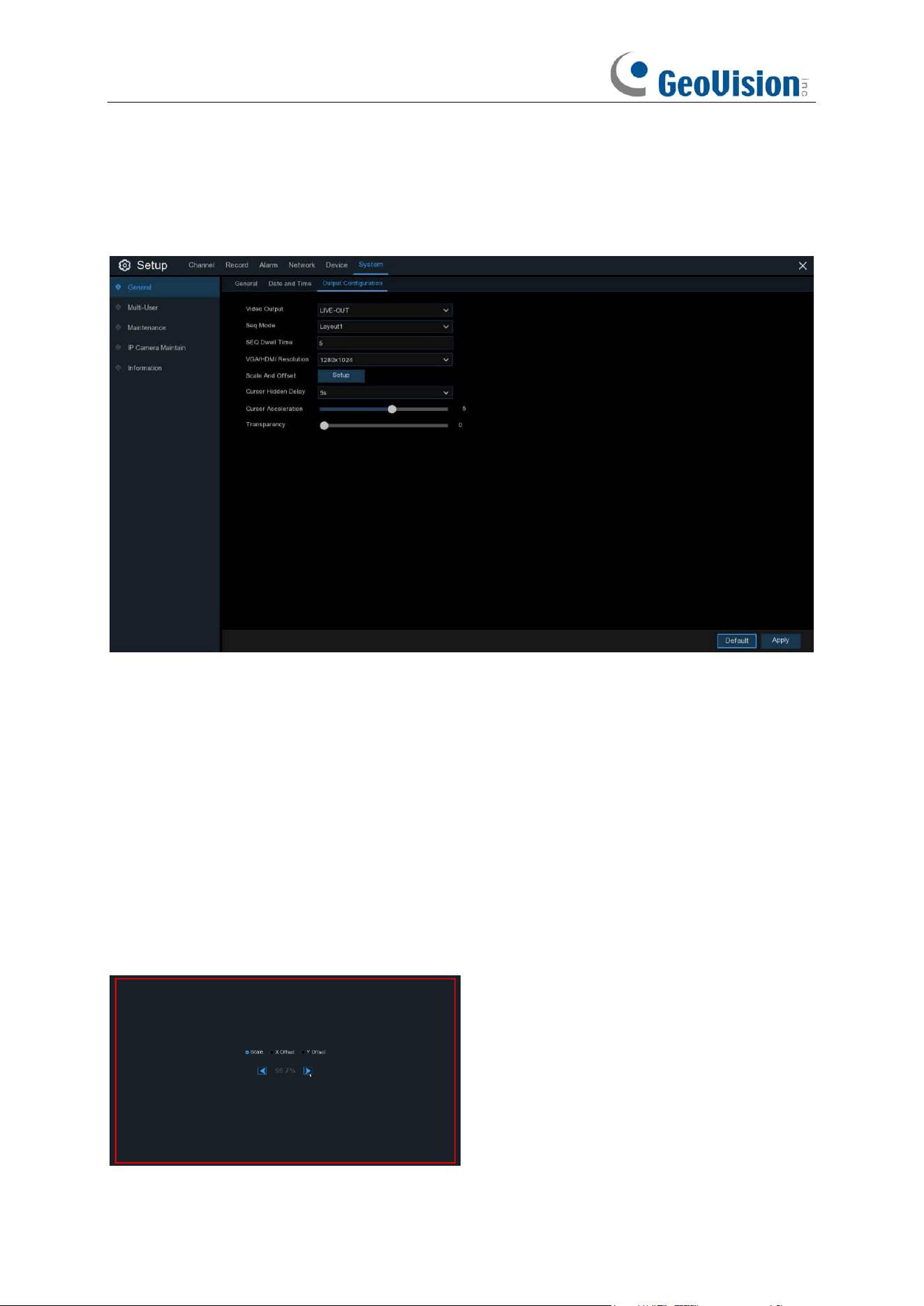
192
5.7.1.4 Output Configuration
This menu allows you to configure video output parameters.
Video Output
: To choose the output options:
LIVE-OUT
is used to configure the main output parameters.
Choose
LIVE-OUT
from the Video Output drop-down menu.
SEQ Mode
: Select how many video channels you would like to display when your NVR is in
sequence mode.
SEQ Dwell Time:
Enter in seconds the maximum length of time you would like to display a video
channel in sequence mode before displaying the next video channel (300 seconds is the
maximum).
Output Resolution
: Select a display resolution that is suitable for your TV. 1920 x 1080 will suit
most TVs. If your NVR supports 4K output resolution, you can select either 2K (2560 x 1440) or 4K
(3840 x 2160) to take advantage of the higher resolution that your 4K TV provides.
Scale and Offset
: The NVR supports to adjust the size & position of the display screen to match
your monitor or TV. Click
Setup
button to adjust.
Scale: To adjust the size of the displayed screen
by scale.
X Offset: To move the displayed screen to left
or right.
Y Offset: To move the displayed screen to up or
down.
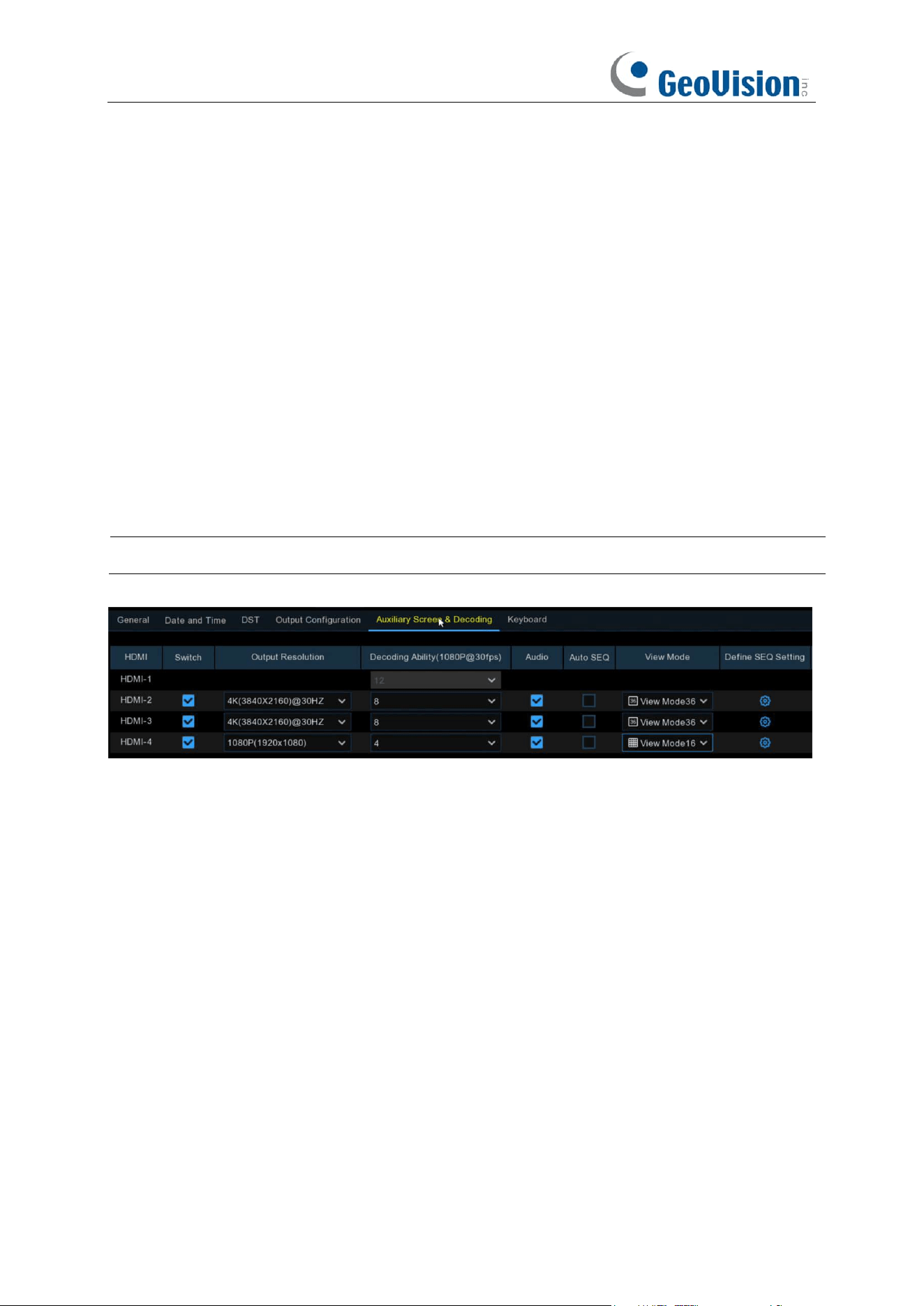
193
Click once or long press the left button of your mouse on the arrow to adjust the size and position,
or you can scroll the wheel of the mouse to adjust. Click the right button of your mouse to exit, and
click
Apply
to save your modifications.
Cursor Hidden Delay
: Click the drop-down menu to select the time your NVR will hide the mouse
cursor when idle. You can also disable this by selecting “OFF” (password protection will be
temporarily disabled).
Cursor Acceleration
: To adjust the speed to move the mouse cursor.
Transparency
: Click and hold the slider left or right to change how transparent the Menu Bar and
Main Menu will appear on-screen. Adjust accordingly.
5.7.1.5 Auxiliary Screen & Decoding
The following three output parameters for secondary screen display should be configured: HDMI-2,
HDMI-3, and HDMI-4.
Note:
The function is only applicable to GV-RNVR256G0-N.
Switch: Used to set whether to enable the secondary screen display.
Output Resolution: Select the display resolution suitable for the secondary screen.
Decoding Ability(1080P@30): Used to set the decoding capability of the secondary screen. For
example, you can set the decoding capability of HDMI-2 to 8, meaning that HDMI-2 can provide a
preview of eight 1080P 30-frame channels.
Audio: Used to set whether to enable the secondary screen audio.
Auto SEQ: Used to set whether to enable SEQ mode on the secondary screen.
View Mode: Select the number of video channels to be displayed statically on the secondary
screen.
Define SEQ Setting: Select the number of channels to be displayed statically on the secondary
screen.
Seq Mode: Select the number of video channels to be displayed in SEQ mode on the secondary
screen.
SEQ Dwell Time: Used to set the SEQ dwell time on the secondary screen in seconds.
Spot Poll Setting: Select the channels for sequential display on the secondary screen in dynamic
mode.
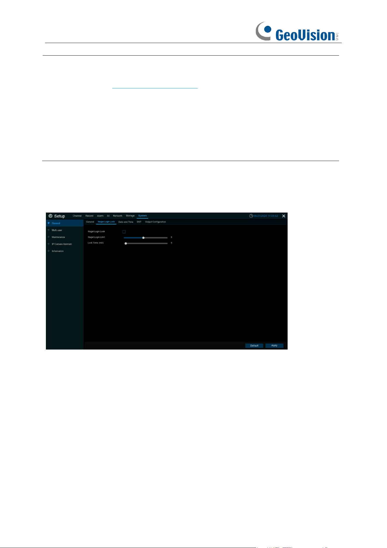
194
Note:
1.
You can set the output resolution of HDMI-1 on the output configuration page. For more
information, see 5.7.1.4 Output Configuration. When the output resolution of HDMI-1 is 8K,
HDMI-2 output will not be available.
2.
A maximum of simultaneous 152 channels of live view is applicable when the following
conditions are fulfilled:
i. With 4 screen display
ii. When HDMI-1 resolution is set to 4K or below
iii. HDMI-1 view mode will be set to 64 channels automatically
5.7.1.6 Illegal Login Lock
Illegal Login Lock:
Check to enable the function.
Illegal Login Limit / Lock Time (min):
Specify to activate the lockout when reaching the number
of failed login attempts and for the lockout duration.
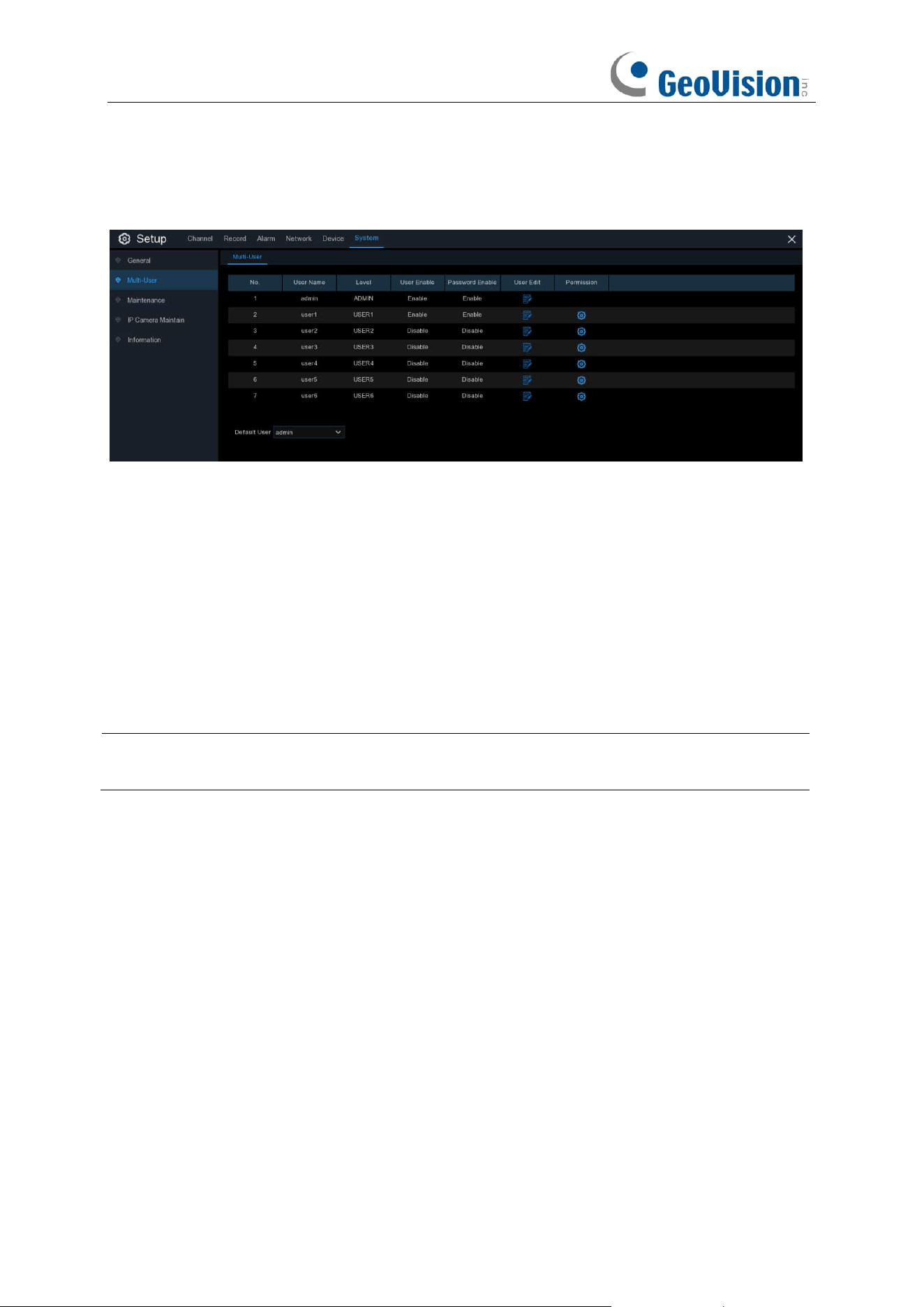
195
5.7.2 Multi-user
This menu allows you to configure the user name, password and user permission.
The system supports the following account types:
•
ADMIN — System Administrator
: The administrator has full control of the system, and
can change both administrator and user passwords and enable/disable password
protection.
•
USER — Normal User
: Users only have access to live viewing, search, playback, and
other functions. You may set up multiple user accounts with varying levels of access to the
system.
• Default User: Select the default user to login the system when the system starts. admin is
the default user account. If multiple user accounts have been created, click the drop-down
menu to turn this off.
Note:
For normal user to be able to change its password, the system administrator must grant
the permission of
Subuser Password Change
first.
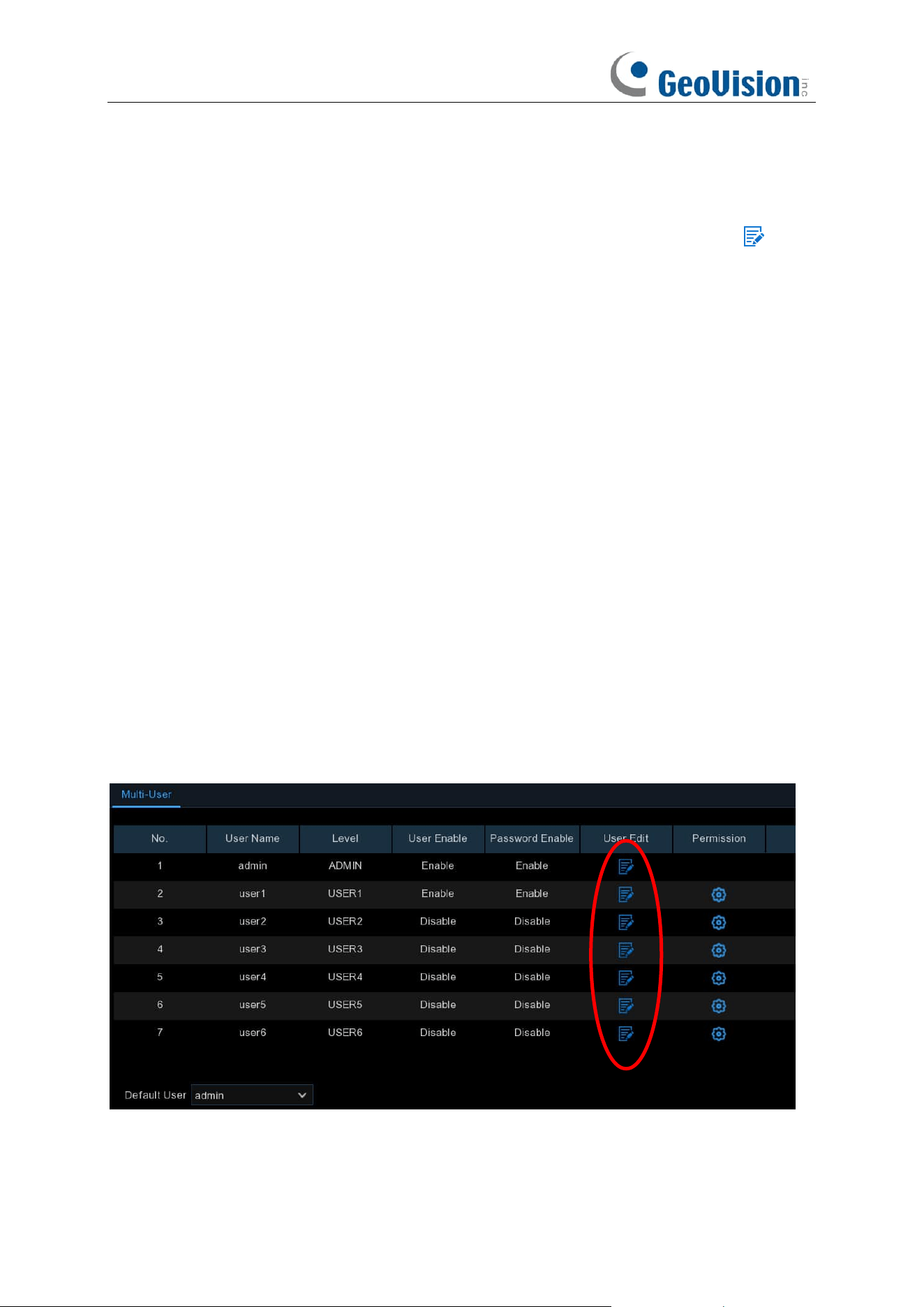
196
5.7.2.1 Changing Password
To change the password for the administrator or user accounts, click the User Edit icon . The
password has to be a minimum of 8 characters and can contain a mixture of numbers and letters.
Enter your new password again to confirm, and then click
Save
to save your new password. You
will be required to input your old password to authenticate.
Password Enable:
It’s strongly recommended to enable the password to protect your privacy. If
you want to disable the password protection, ensure your NVR is placed in a secure place.
5.7.2.2 Adding New Users
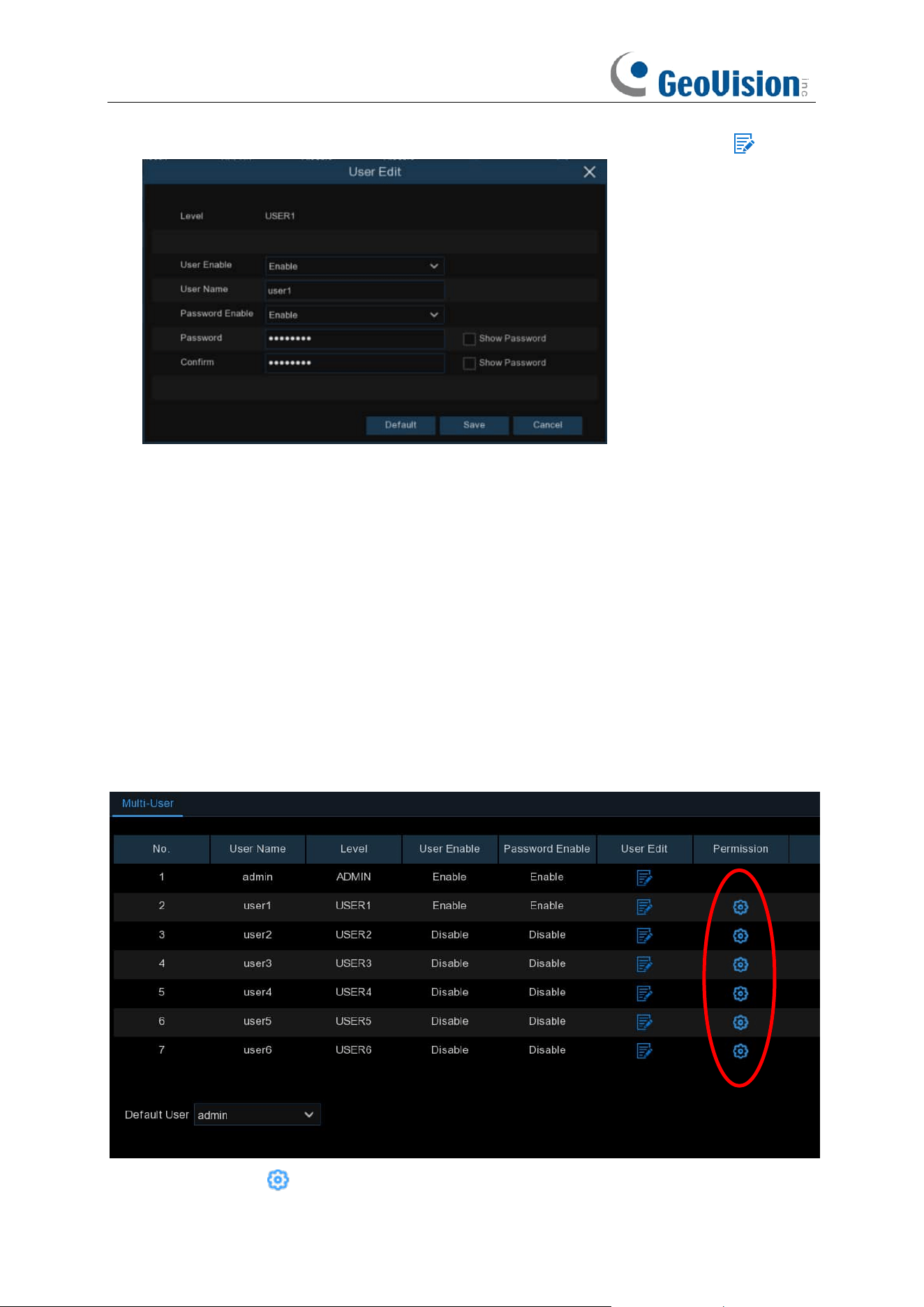
197
1. Select one of the user accounts that is currently disabled, click the User Edit icon .
2. Select
Enable
from the drop-down next to
User Enable
.
3. Click the field next to
User Name
to change the user name for the account.
4. Select
Enable
from the drop-down next to
Password Enable
.
5. Click the field next to
Password
to enter the desired password.
6. Click the field next to
Confirm
to reenter the password.
7. Click
Save
. You will be required to input your Admin password to authenticate.
5.7.2.3 Setting User Permissions
The administrator account is the only account that has full control of all system functions. You can
enable or disable access to certain menus and functions of each user account.
1. Click the edit icon under Permission tab.
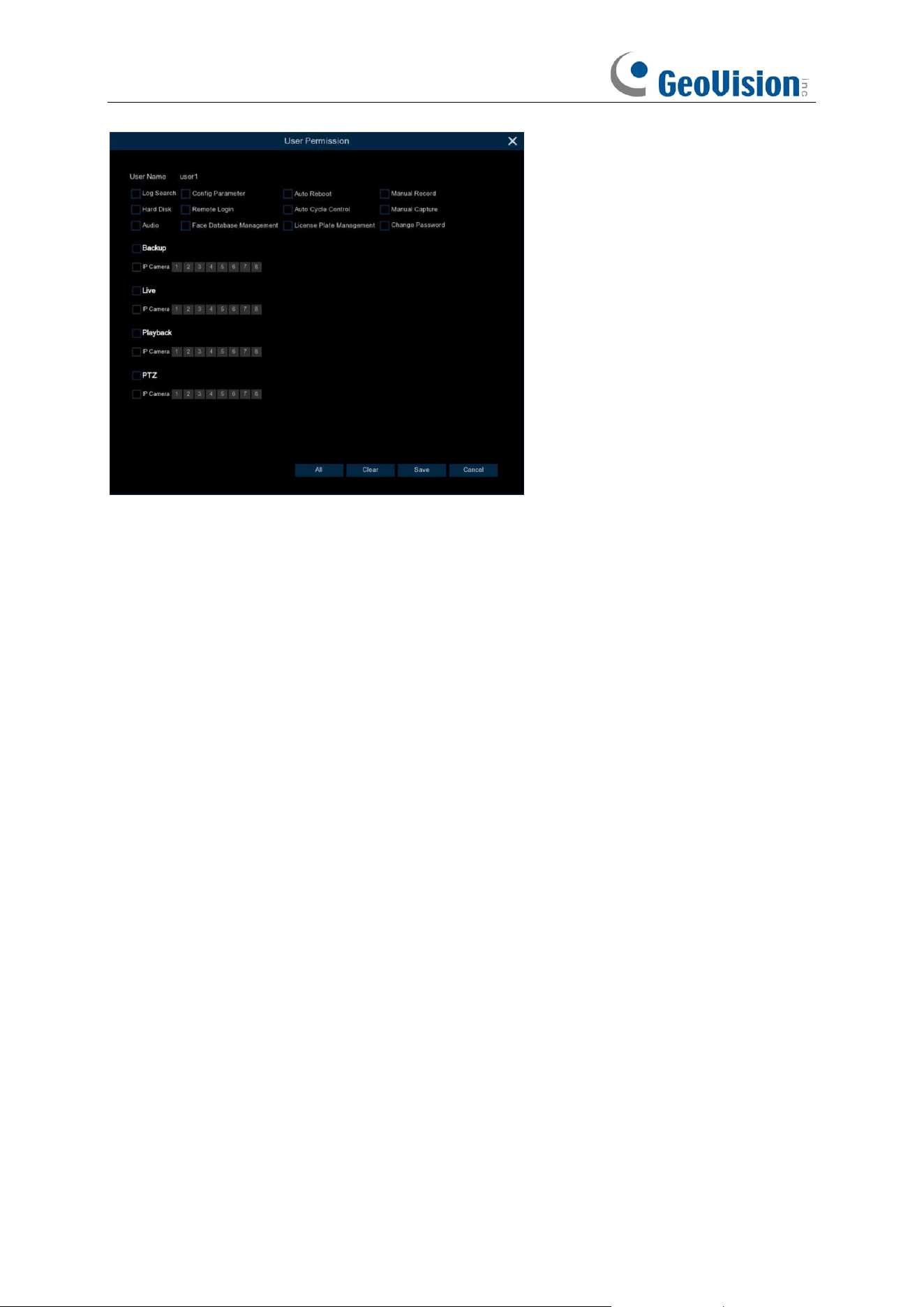
198
2. Check the boxes next to any system menus or capabilities you would like the user to access.
Click
All
to check all boxes. Click
Clear
to check none of the boxes.
3. Click
Save
to save your modifications.
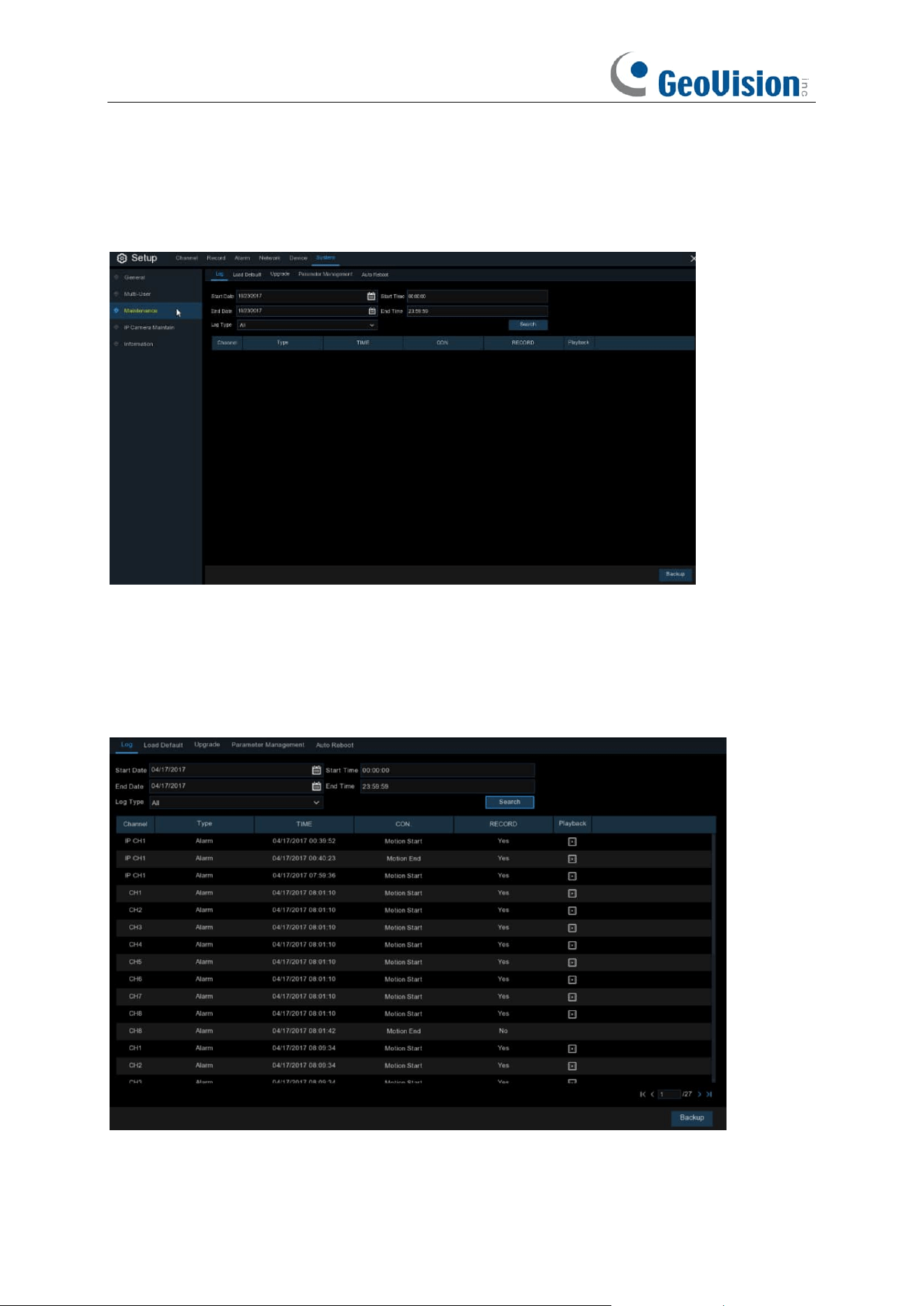
199
5.7.3 Maintenance
In this section, you will be able to search & view the system log, load default settings, upgrade the
system, export & import system parameters and manager system auto reboot.
5.7.3.1 Log
The system log shows you important system events, such as motion alarms and system warnings.
You can easily create a backup file of the system log for a set time period to a USB flash drive.
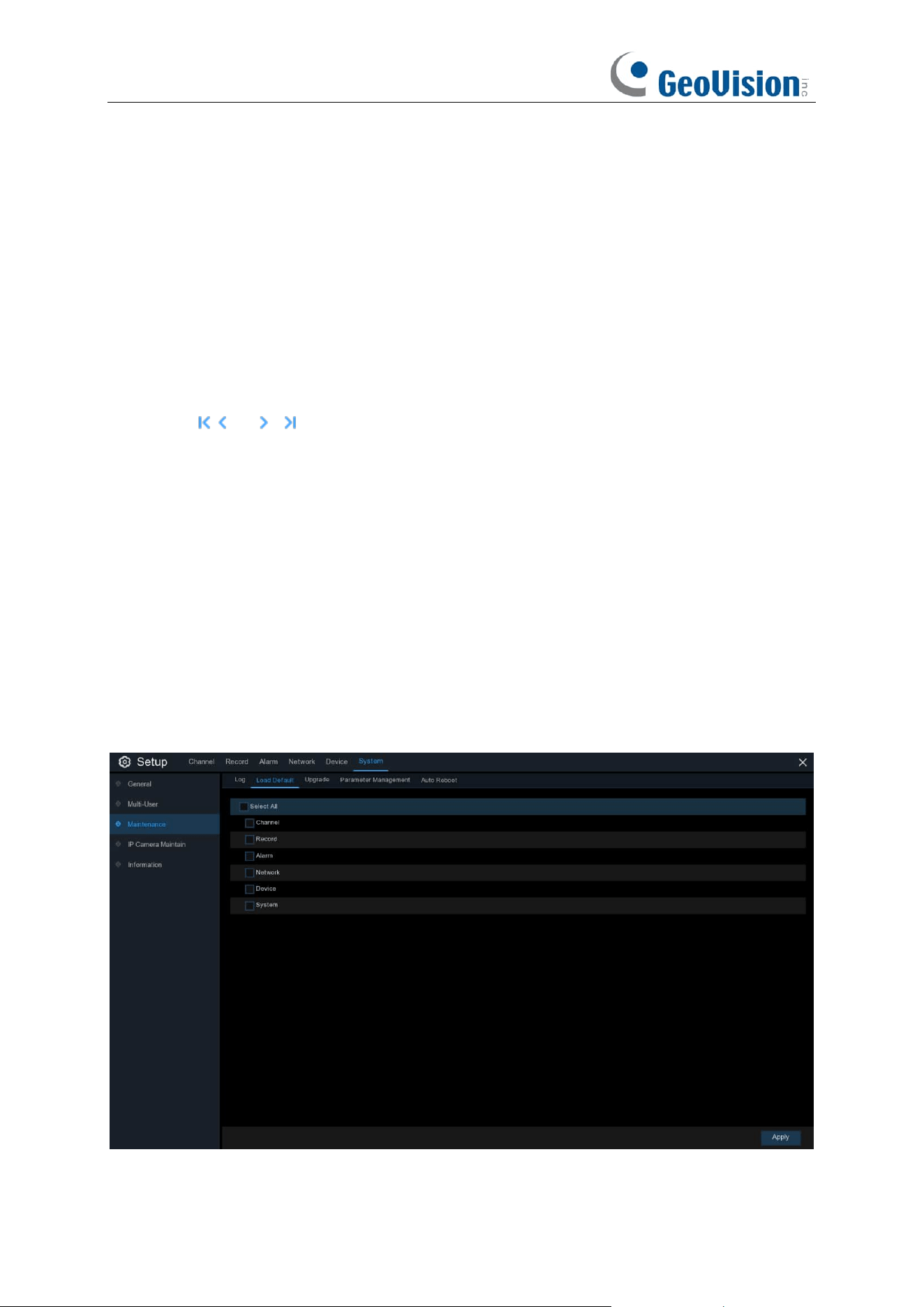
200
Log Searching and Backing Up:
1. Click the field next to
Start Date
&
Start Time
to choose the starting date & time for your
search from the on-screen calendar.
2. Click the field next to
End Date
&
End Time
to choose the end date & time for your search from
the on-screen calendar.
3. Select the type of events you would like to search for from the dropdown next to
Log Type
, or
select
All
to see the entire system log for the selected time period.
4. Click
Search
.
5. Browse system log events from your search period:
o
Video events can be played back instantly by clicking in the
Playback
column. Right-click to
return to your search results.
o
Use the / buttons in the bottom-right corner of the menu to move between pages
of system log events.
6. Click
Backup
to create a backup of the system log for your search period. Make sure your flash
derive has been connected to the NVR’s USB port.
7. The backup drive menu appears. Navigate to the folder you want the backup file to be saved in,
then click
OK
to begin.
5.7.3.2 Load Default
Reset the NVR settings to its out-of-box state. You can choose to reset all settings at once, or just
settings on specific menus. Restoring default settings will not delete recordings and snapshots
saved to the hard
drive.
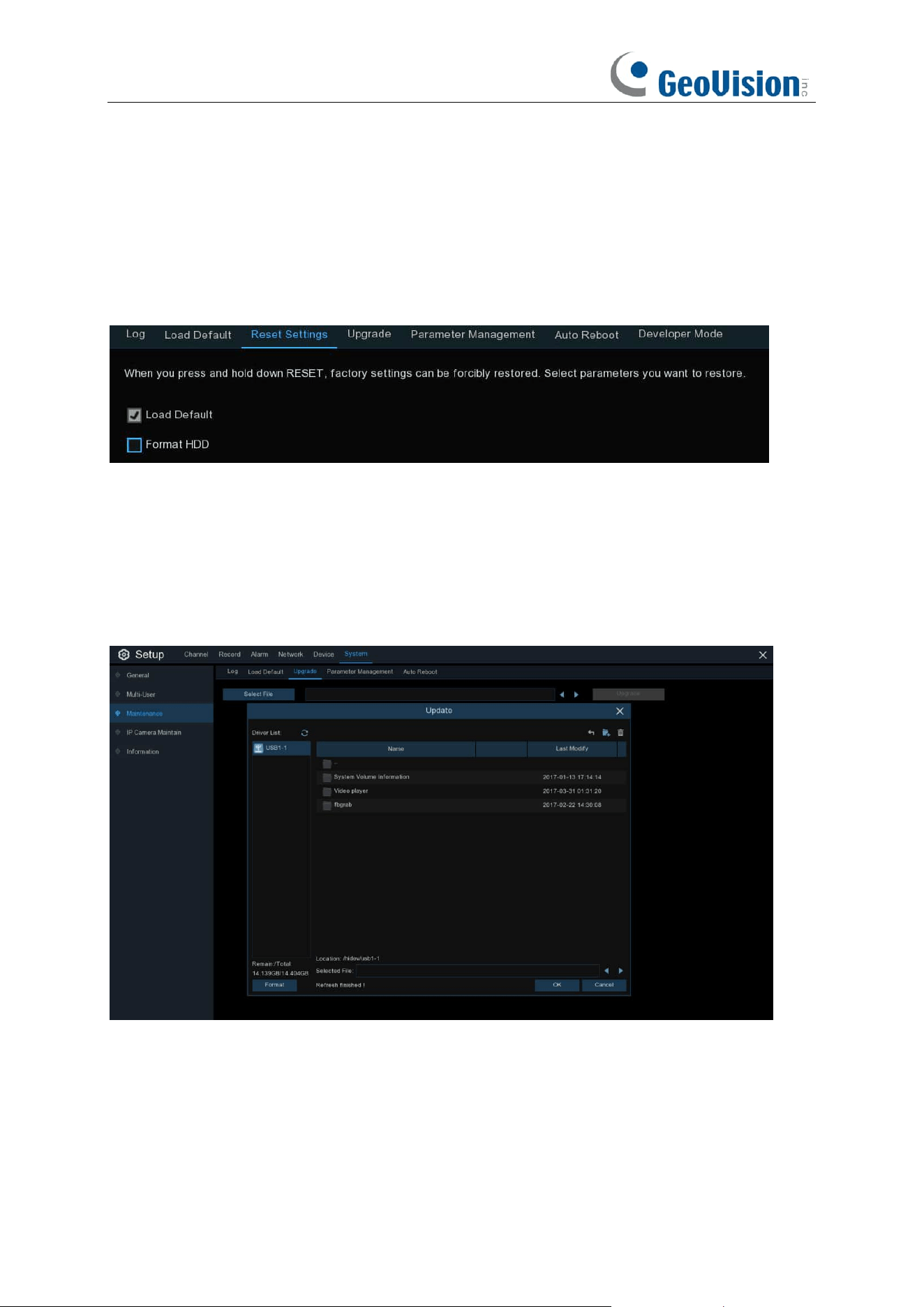
201
Check the items you want restore, or check
Select All
to choose all items. Click
Apply
to load
default settings of your chosen items.
5.7.3.3 Reset Settings
If your NVR comes with a reset button on the rear panel, you will see this menu.
By default, when you press and hold 10 seconds on the reset button with a small pin till the NVR
beeps, the NVR will restore default settings. You can tick the checkbox to format HDD if needed.
5.7.3.4 Upgrade
1. Copy the firmware file (.sw file) to your USB drive, and insert the USB flash drive into the NVR’s
USB port.
2. Click Select File button to choose the firmware file in your USB flash drive, then Click
OK
.
3. Click
Upgrade
button to start system upgrade. The system upgrade will last around 5-10
minutes, do NOT power off the NVR or remove the USB from NVR during firmware upgrade.
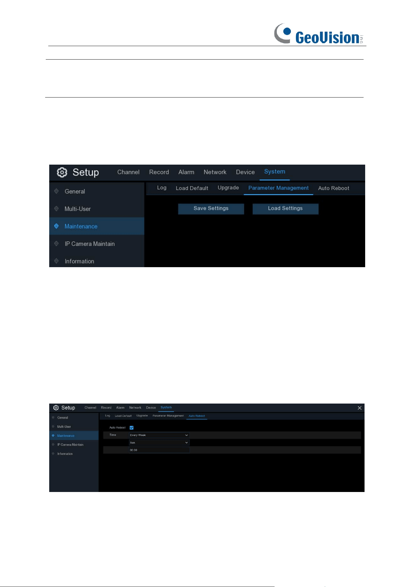
202
Note:
You can optionally upgrade the firmware using
GV-IP Device Utility
(V9.0.1 or later). See
Chapter 5.2 Upgrading Firmware Using GV-IP Device Utility in GV-RNVR256G0-N Quick Start
Guide.
5.7.3.4 Parameter Management
You can export the main menu settings you have configured to a USB flash drive, or import an
exported setting file from USB flash drive to the NVR.
Save Settings
: Click to save the NVR current system settings to the USB device. You will be
required to input the Admin password to authenticate.
Load Settings
: Once you have created a system settings export, you can import the settings on
another NVR. Click
Load Settings
button to
navigate to the system settings file you want to
import from your USB flash driver.
You will be required to input the Admin password to
authenticate.
5.7.3.5 Auto Reboot
This menu allows the system to auto reboot the NVR regularly. It is recommended to leave this
function enabled, as it maintains the operational integrity of your NVR.
Auto Reboot
: Check to enable.
Time:
You can set the NVR to reboot by day, week or month.
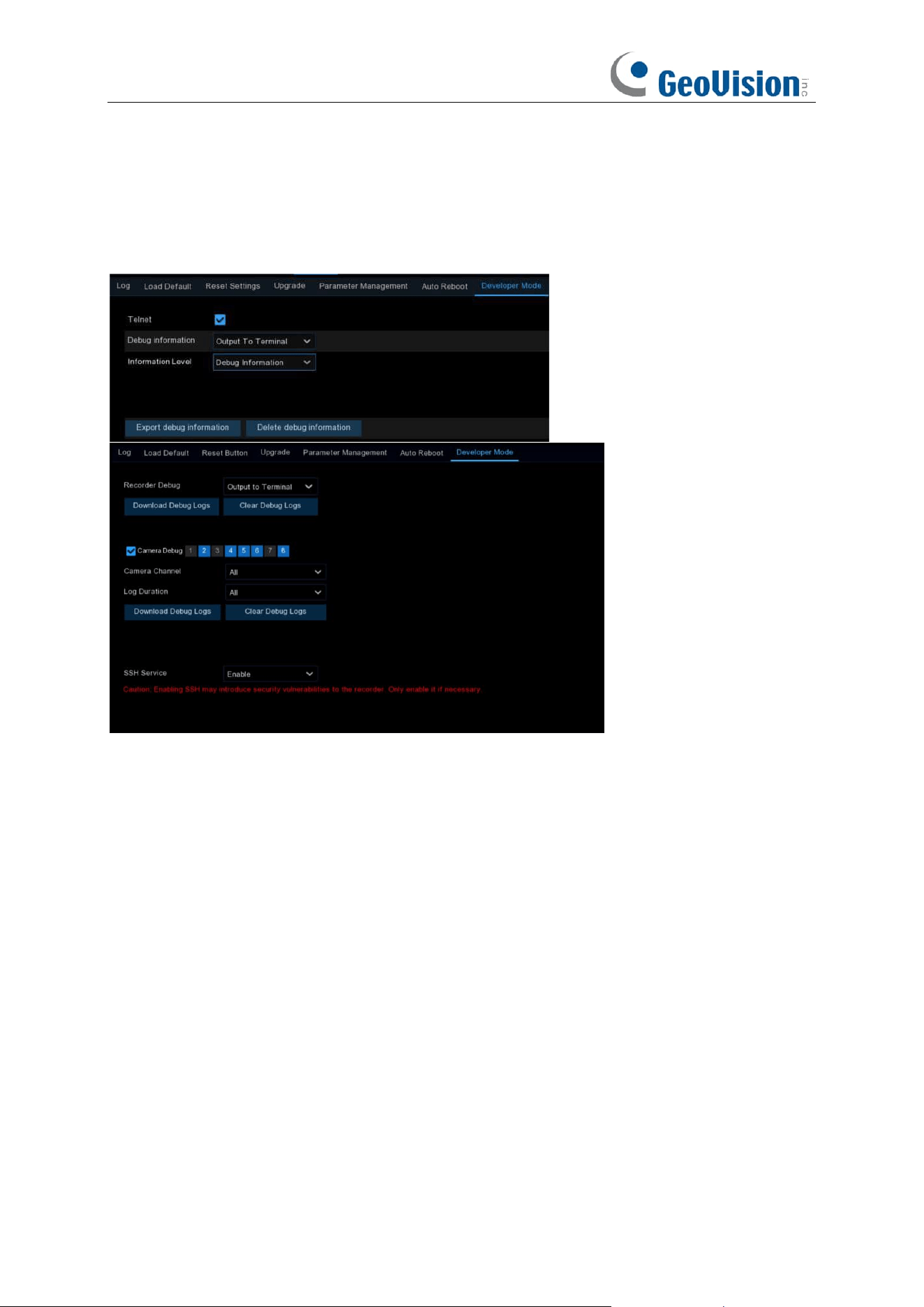
203
5.7.3.6 Developer Mode
This is an advantage feature on some certain models, which is used to acquire debug log for
authorized professionals when you report a defective complaint.
Telnet: This is used for an authorized technician to connect to your NVR remotely. Please keep it
disabled unless you're required by an authorized technician.
Debug Log / Recorder Debug: It is used for authorized professionals to learn the system running
status.
➔
Disabled:
Debug log won't be saved.
➔
Output to Terminal:
Debug log will be outputted to terminal port.
➔
Output to Disk:
Debug log will be saved to hard disk drive.
Information Level: Used to set the printing level of serial port log information. To enable technical
personnel to quickly locate problems, you can set the log output levels in accordance with the
device maintenance requirements.
System Information: Only system-level logs (such as low-level drivers) and necessary
information during program operation are outputted.
Error Information: In addition to system information, the errors or exception information
during program operation are also included in the error log.
Running Information: In addition to the error log, some important information during
program operation is also outputted for the developer to analyze the program running status.

204
Debug Information: In addition to running information, the relevant information added by the
developer in advance to assist debugging and positioning is also outputted. There is much print
information at this level, which may affect device operation. In general, it is recommended that this
option be disabled.
Debug Trace Information: At this level, more detailed debug information is output, further
assisting technical personnel to analyze and position the bugs of functional modules. This option
is enabled only when the technical personnel clearly require more detailed information.
Export Debug Log: Export the debug log file from hard disk drive to your USB flash drive.
Delete Debug Log: Delete the debug file from the hard disk drive.
Camera Channel
: Set whether to record the camera's serial logs to the VCR, select the channel
and save, the corresponding channel of the camera debug logs will be transmitted to the VCR side
for saving.
Log Duration:
Set the debug log duration.
Download Debug Logs:
Export the camera debug logs to a USB flash drive, supporting saving
by channel and recording time.
Clear Debug Logs:
Deletes the camera debug logs stored on the hard disk.
SSH Service:
When enabled, you can use SSH to access the device.
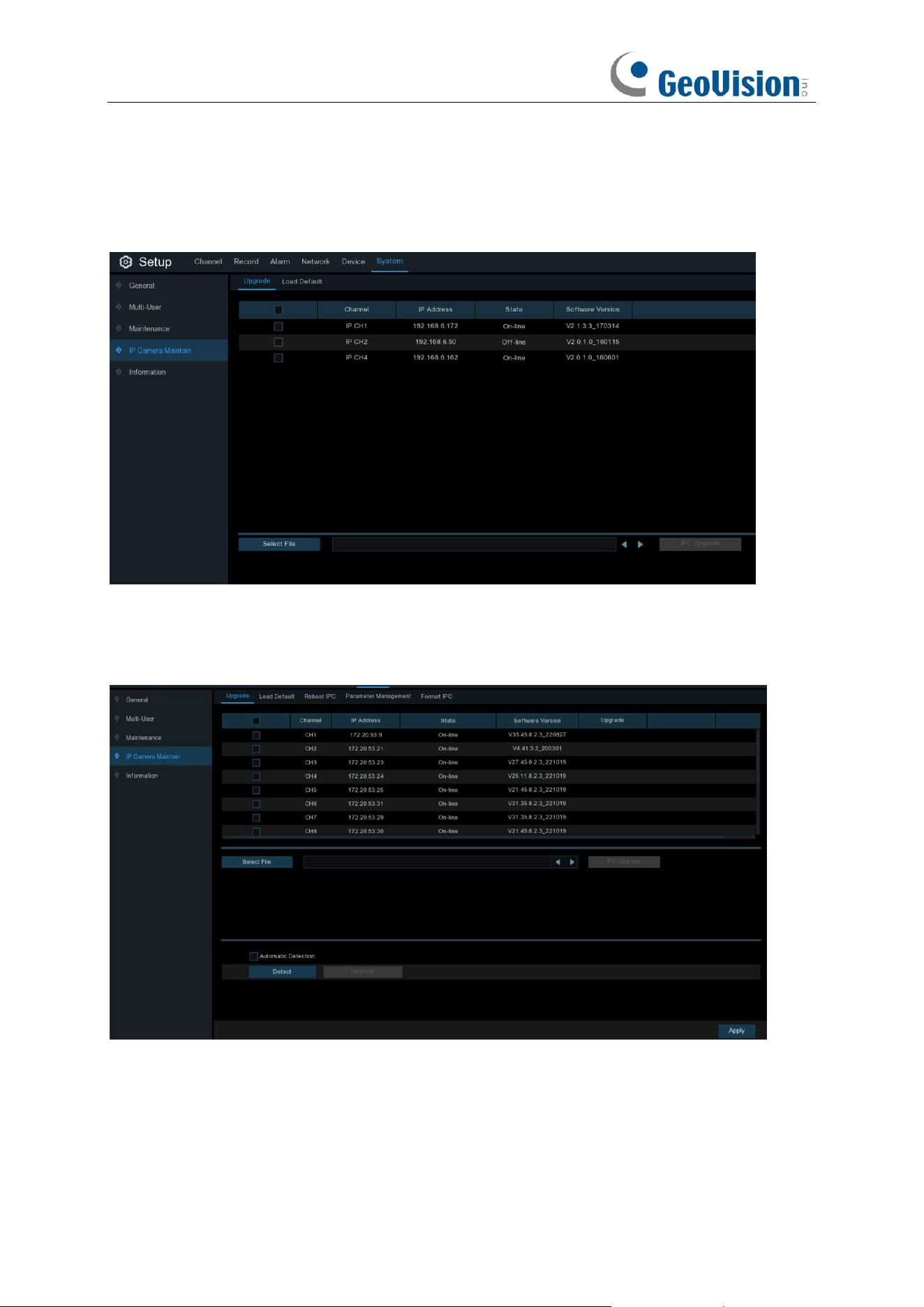
205
5.7.4 IP Camera Maintain
This menu allows you to upgrade the IP camera’s firmware and restore default settings of IP
camera.
5.7.4.1 Upgrade IP Camera
1. Choose one of the IP cameras you want to upgrade firmware.
2. Click
Select File
select the update file from your USB flash drive, then click
OK
.
3. Click
IPC Upgrade
button to start upgrading. You will be required to input the Admin password
to authenticate. Do NOT power off the NVR and IP camera or remove the USB during the
upgrading.
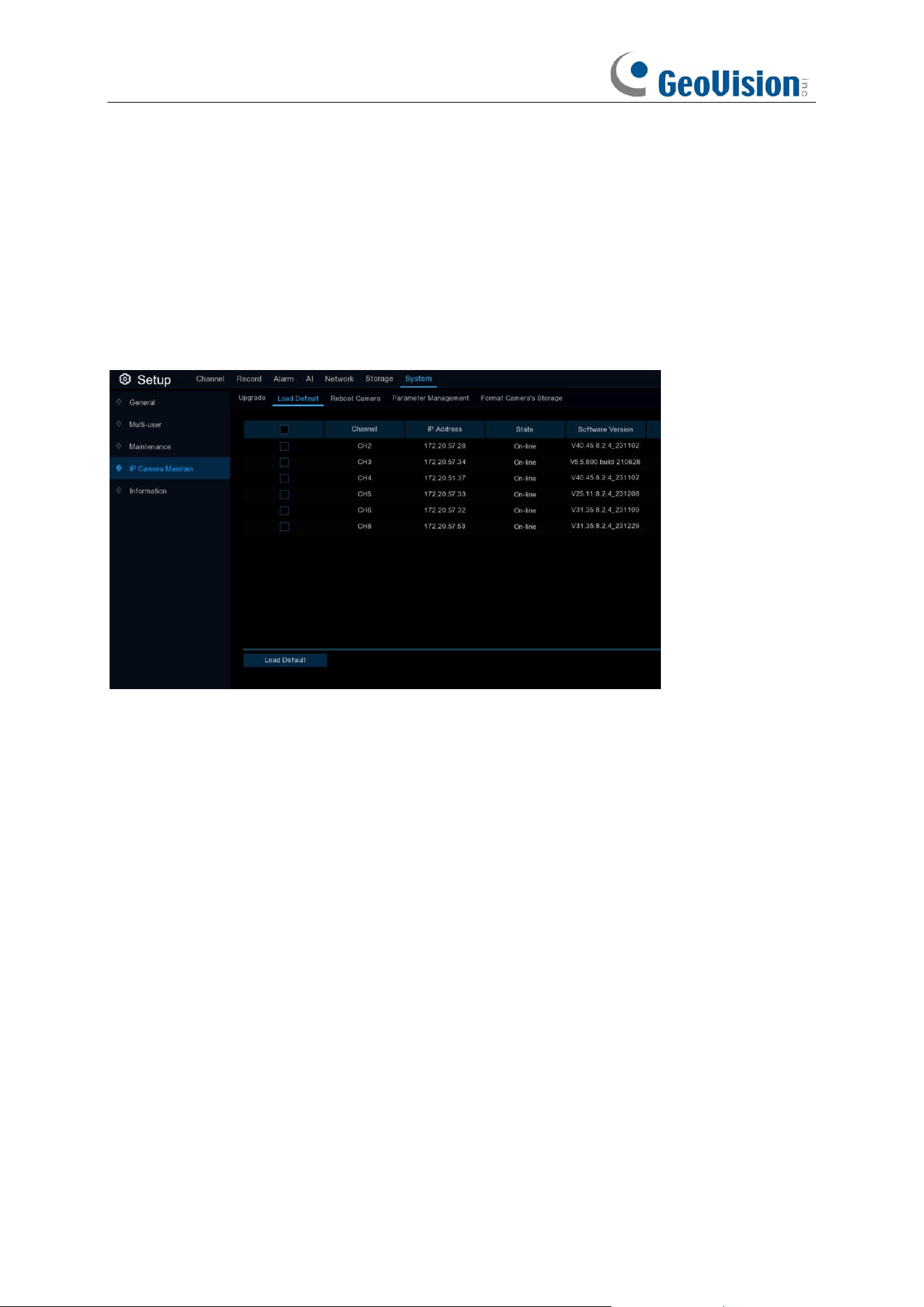
206
For some certain IP cameras which support online upgrade, you can tick "Automatic Detection" if
you want to automatically check the upgrade file from server at regular intervals.
Click Detect button to check if new firmware is available instantly. If new firmware is available,
follow the on-screen instructions.
5.7.4.2 Load Default Settings for IP Camera
1. Choose the IP cameras you want to restore.
2. Click
Load Default
to restore settings.
You will be required to input the Admin password to
authenticate.
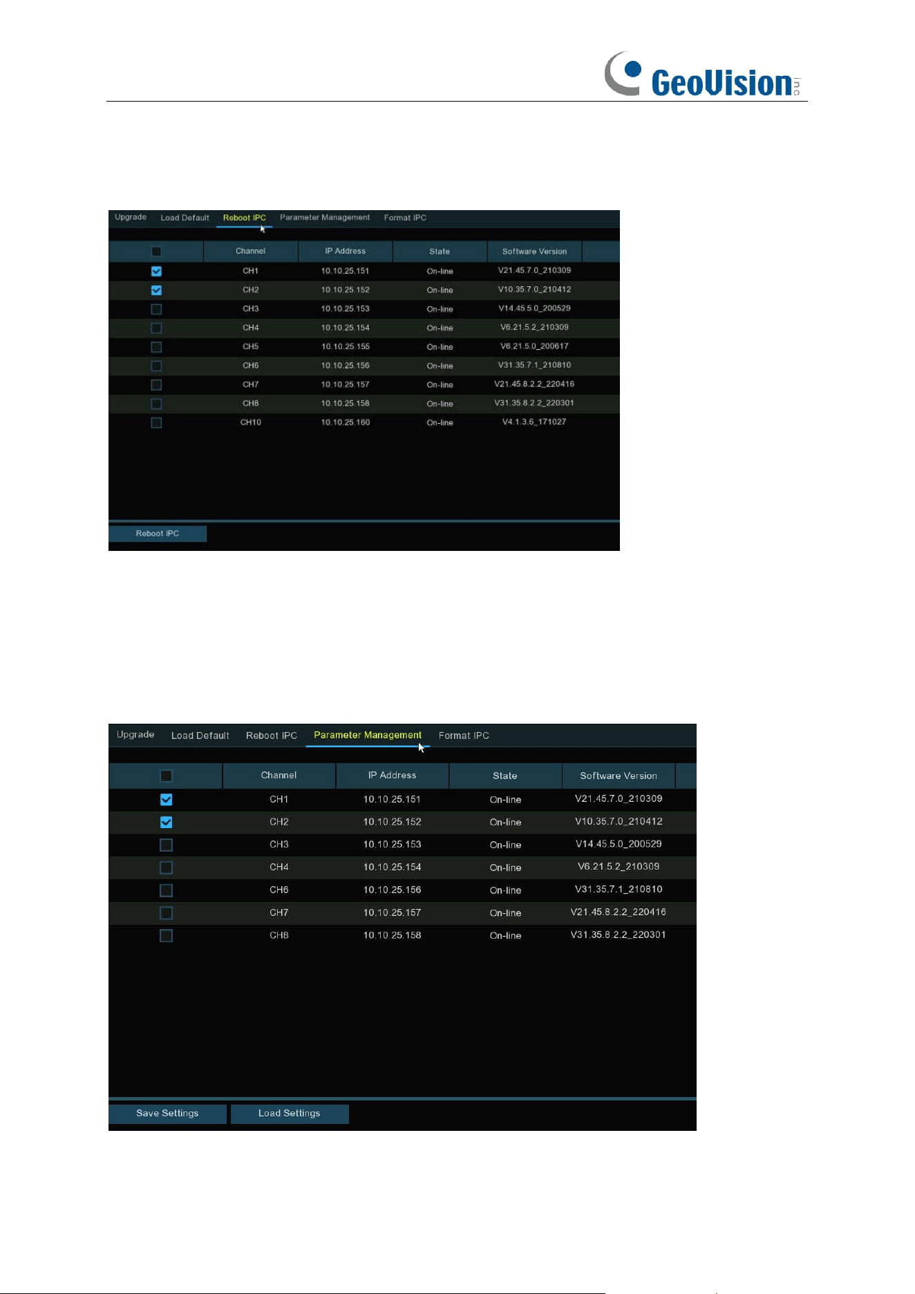
207
5.7.4.3 Reboot IP Camera
In case of any issues, choose the camera(s) and then click "Reboot IPC / Camera" button to
reboot selected camera(s).
5.7.4.4 Parameter Management
Select the camera(s), and then click "Save Settings" to export the configuration file containing all
the settings that you have customized to your USB flash drive.
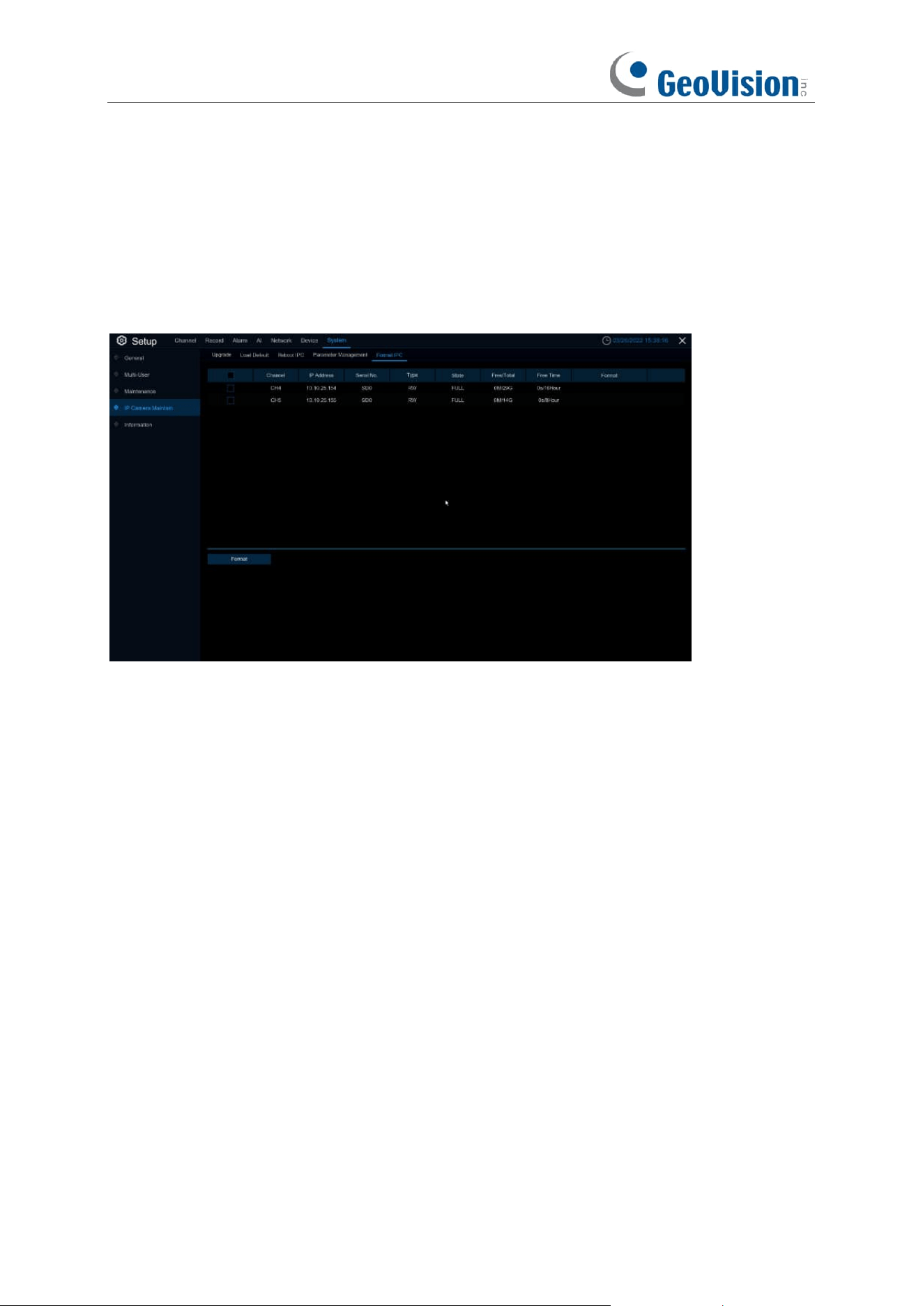
208
Load Settings: Click this button to import a configuration file containing all the settings that you
have customized and apply to the selected camera(s).
5.7.4.5 Format IP Camera
To format the SD card installed on the supported IP camera.
Select the camera, and then click "Format" to format its SD card.
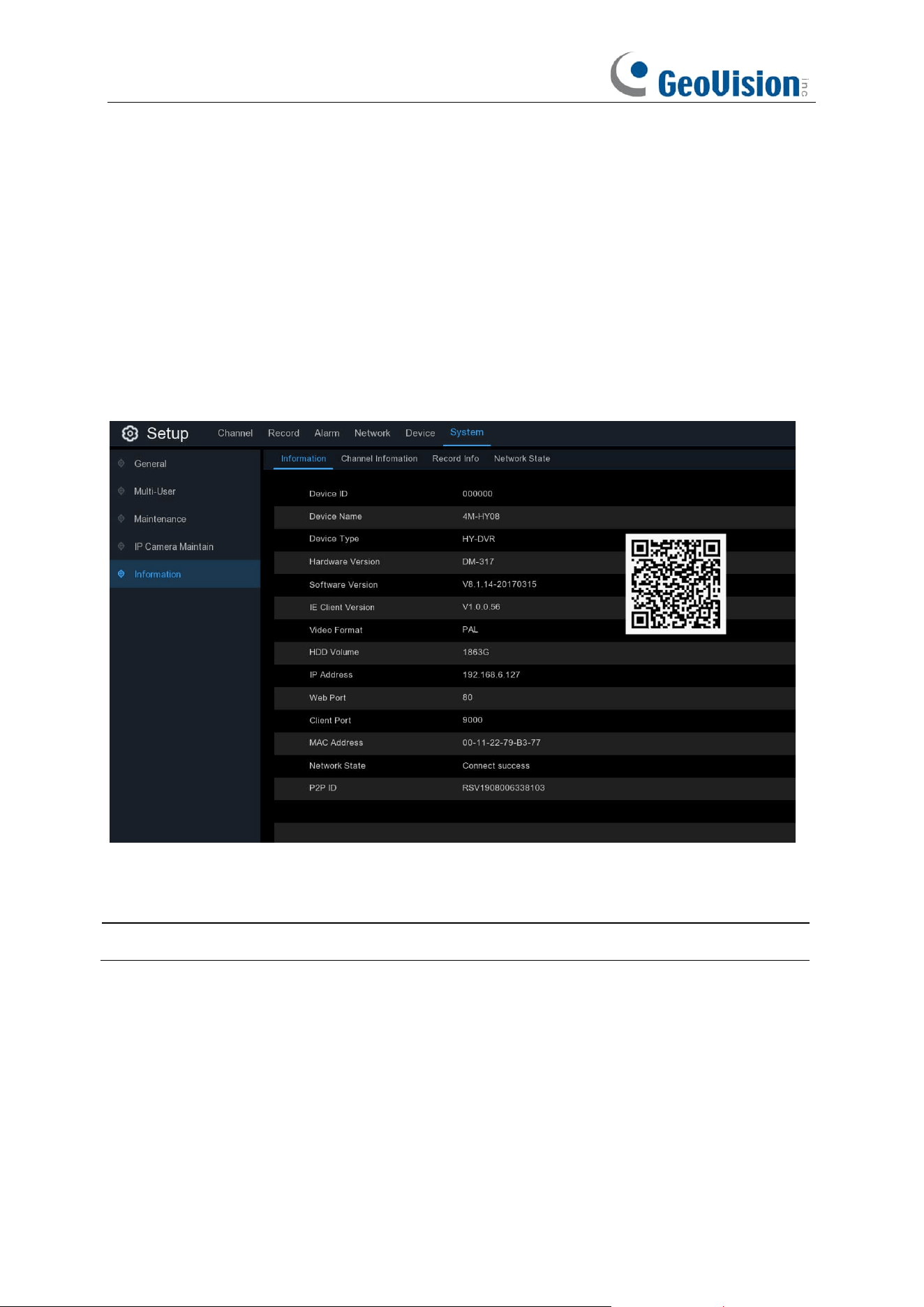
209
5.7.5 System Information
This menu allows you to view the system information, channel information, record information &
network status.
5.7.5.1 Information
View system information such as device ID, device model name, IP address, MAC address,
firmware version and more.
If your NVR supports P2P function, you will find the P2P ID & P2P QR code in the information
page. You can scan this QR cord with the mobile app to remote view the NVR.
Note:
The P2P function is only available in GV-Eye mobile app V3.2.0 or later.
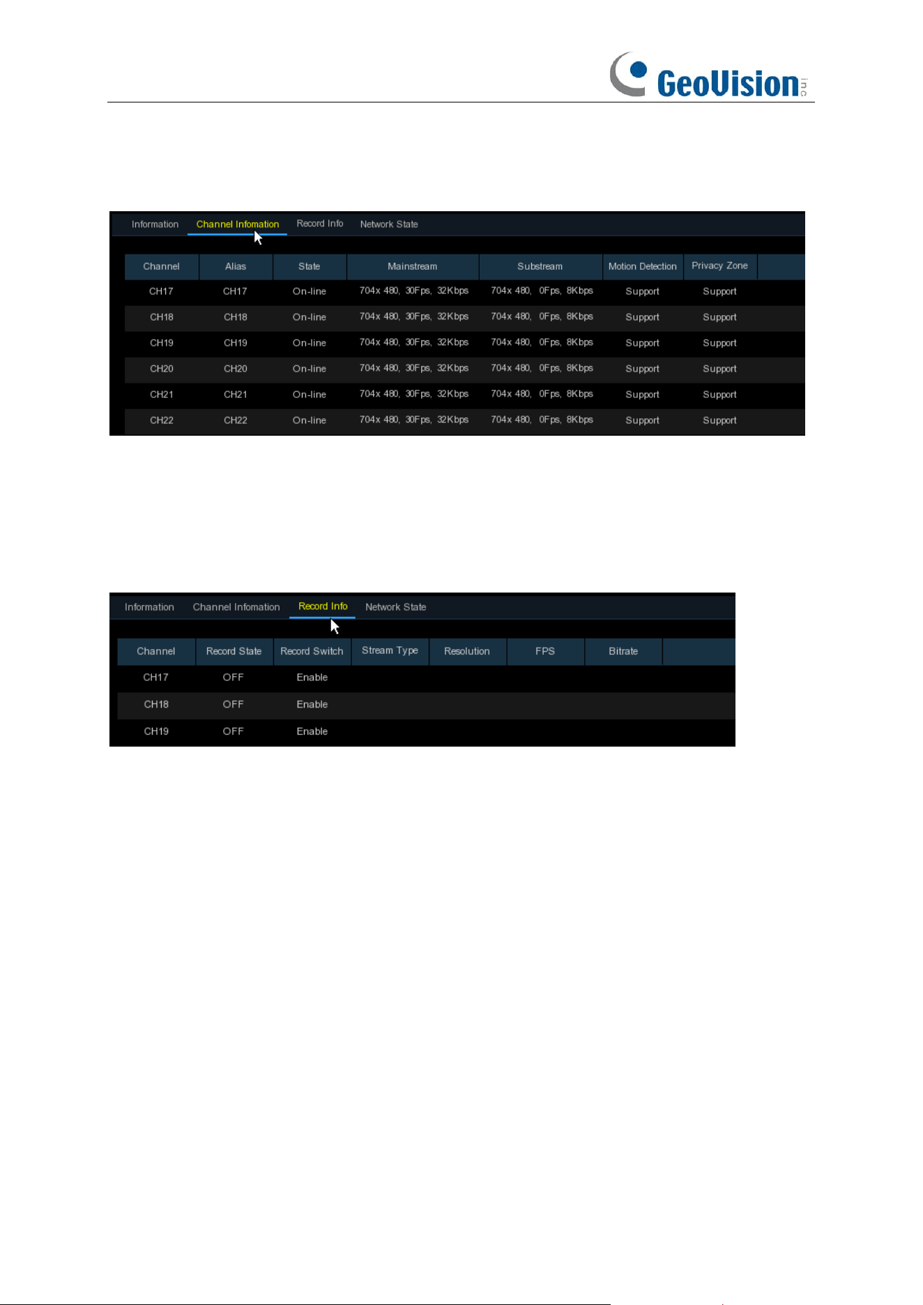
210
5.7.5.2 Channel Information
View channel information for each connected camera such as alias, mainstream and substream
recording specifications, motion detection status & privacy zone.
5.7.5.3 Record Information
View recording information for each connected camera such as bitrate, stream type, recording
resolution and frame rate (FPS).
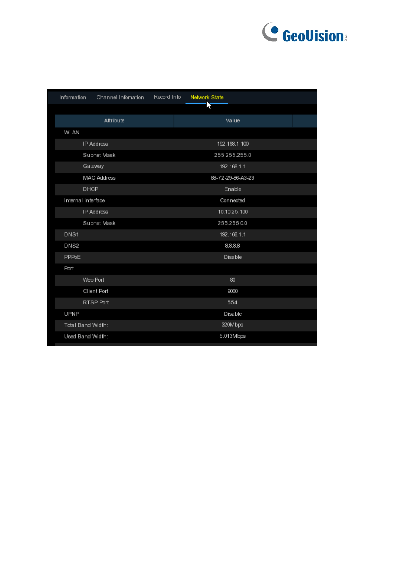
211
5.7.5.4 Network State
View network information.
Total Band Width:
It shows the NVR’s total input band width for IP cameras.
Used Band Width:
It shows the used band width of IP cameras.
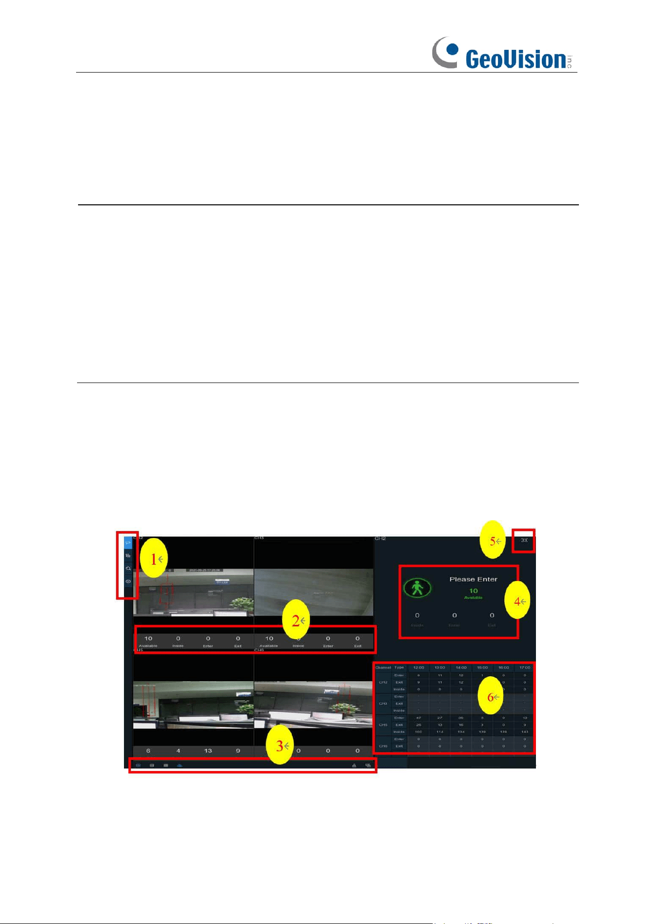
212
Chapter 6 AI Scenario
AI Scenario function provides AI applications for different specific scenarios. Click the submenu
title in the main setup page to get into the individual function setup page.
Note:
1. The AI Scenario functions are only applicable when connected to the following R Series
AI-capable GV-IP cameras. Make sure the corresponding AI functions are enabled on the
cameras.
⚫ GV-RBL5800
⚫ GV-RBL5811
⚫ GV-REB5800
⚫ GV-RMS32810
2. These settings are not available on the NVR’s Web interfaces.
6.1 Cross Counting
This is an AI application based on cross counting function, which helps to control the attendance
number of customers/visitors/vehicles in public places, like restaurants, parks, zoos, theaters,
museums, car parks, etc.
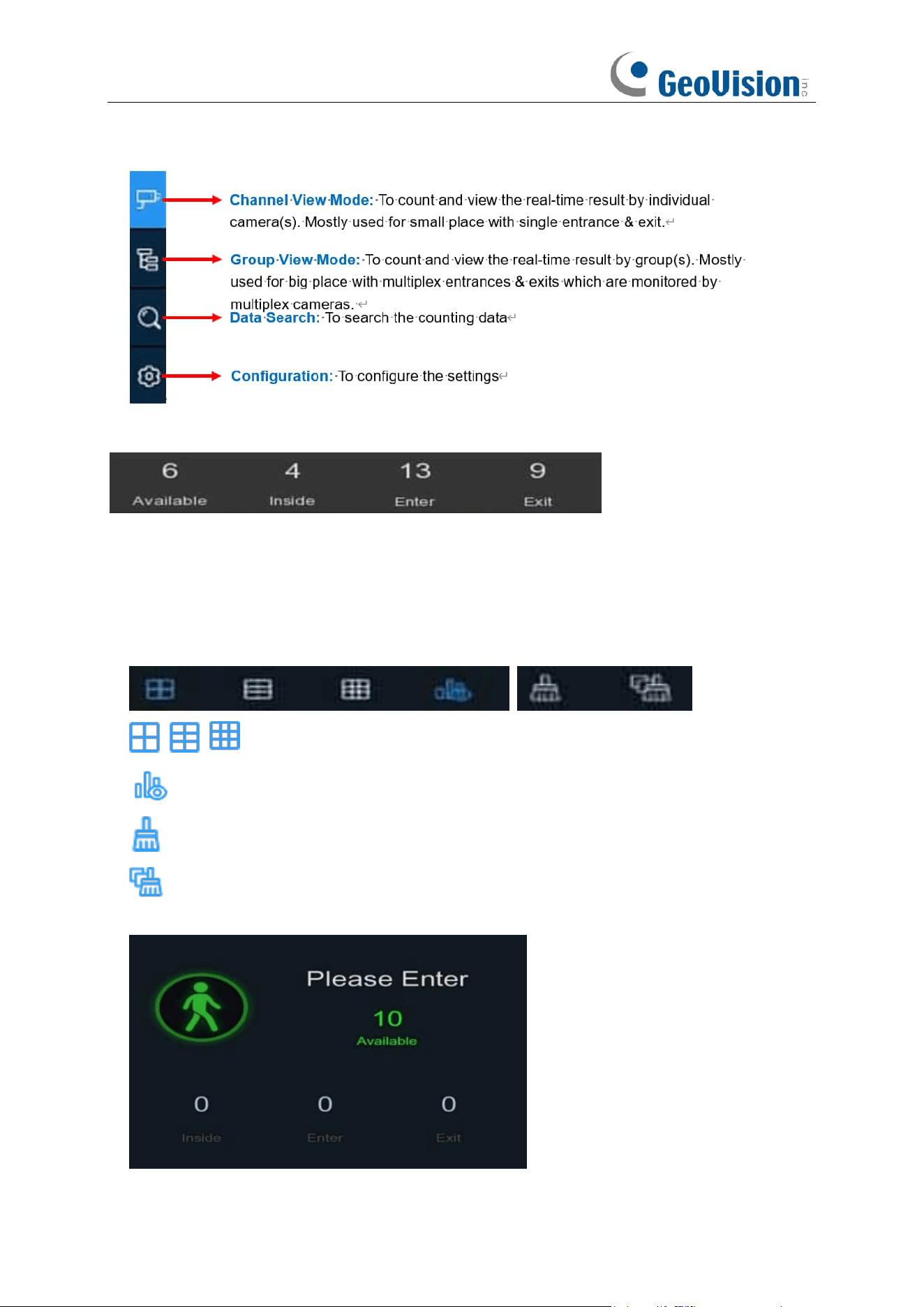
213
1. Navigation bar on the left side:
2. Real-time data display:
Available: Remaining allowed attendance number
Inside: Current attendance number inside the control area
Enter: Recorded number of total entrants
Exit: Recorded number of total leaving attendance.
3. Real-time counting data display:
Screen display layout of 4/6/9 channels.
To show or hide the real-time data display.
Clear counting data for the selected channel
Clear counting data for all channels
4. Real-time counting data information bar
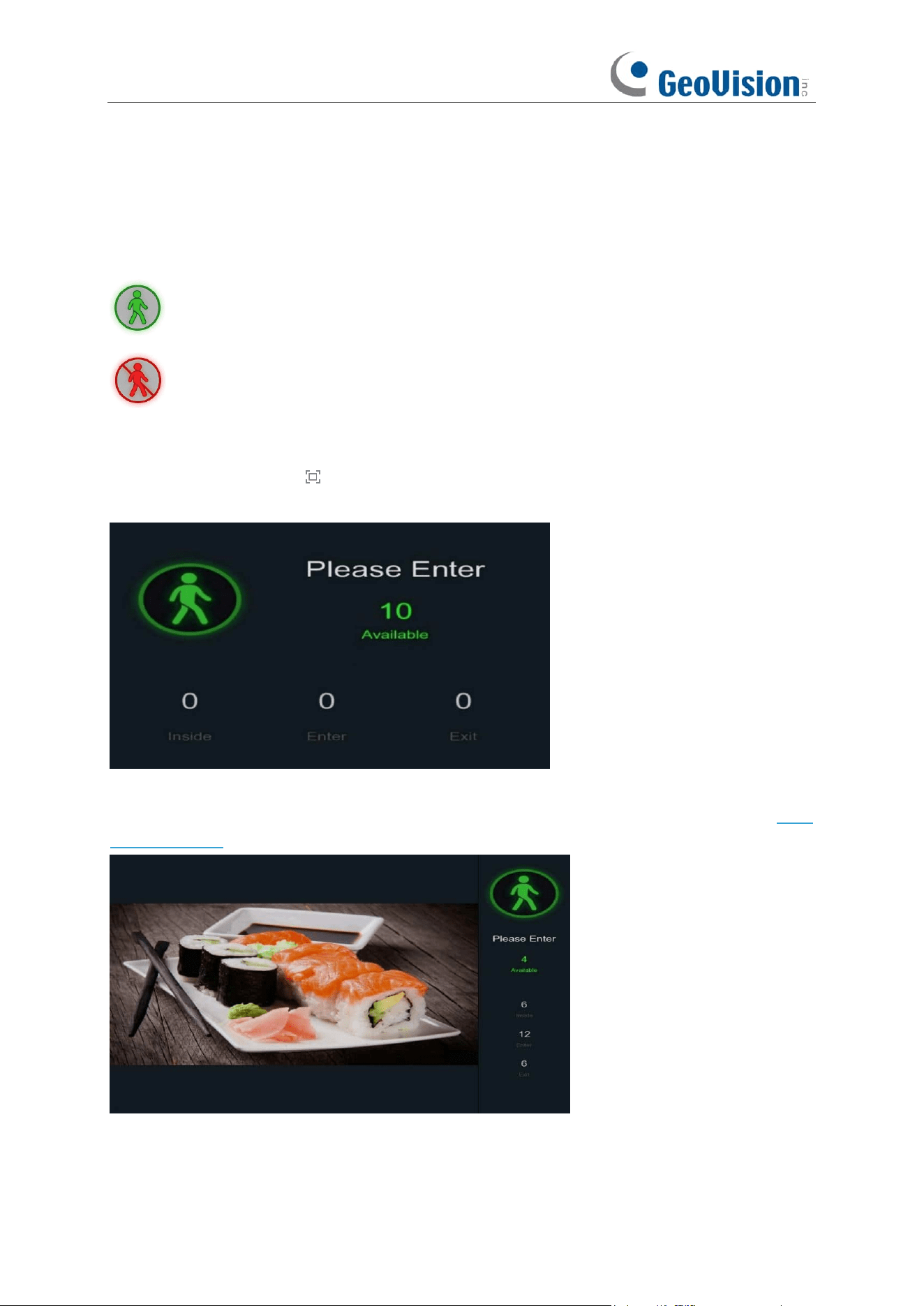
214
This bar will display the real-time counting data for the selected channel.
Available: Remaining allowed attendance number
Inside: Current attendance number inside the control area
Enter: Recorded number of the total entrants
Exit: Recorded number of the total leaving attendance.
If the available number is more than 0, the figure will be in green color.
If the available number is 0, the figure will be in red color.
5. Full Screen Button:
Click the full screen icon to display the real-time counting data for the selected channel(s)
or group(s).
If you have enabled the
Advertise Mode
, your advertising pictures will be displayed with the
real-time counting data together in the full screen mode. Learn more for
Advertise Mode
on 6.1.3
Advertise Mode.
Right click your mouse to exit the full screen mode.
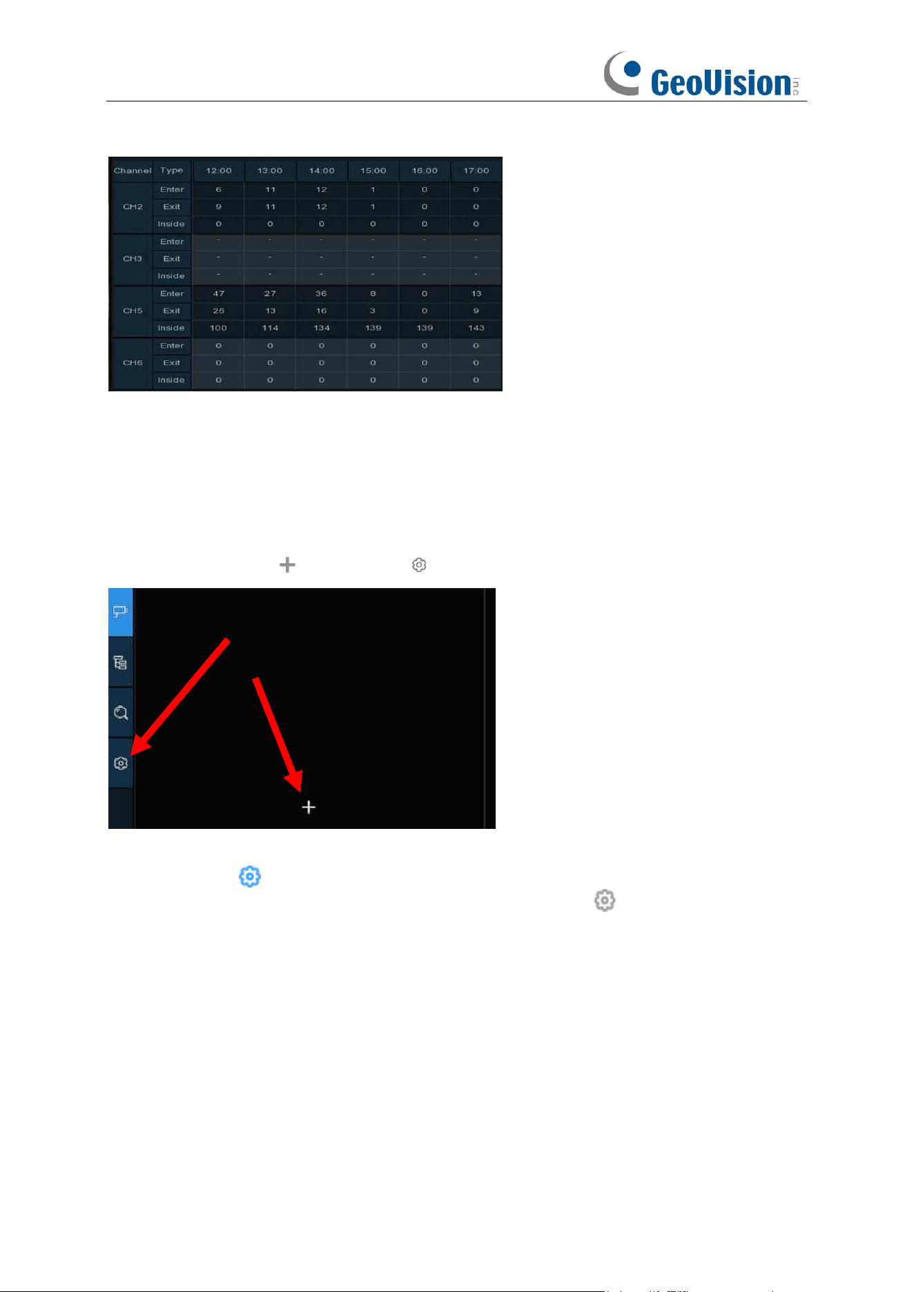
215
6. Statistic data chart:
The all-day counting statistical data of all activated channels will be displayed below the real-time
counting data information. Use the mouse wheel to move the timeline toward left or right.
6.1.1 Channel View Setup
1. Click the add icon or setup icon to get to the configuration page.
2. Enable the channel(s) you want to realize the counting function in the
Channel
list. The Setup
& Alarm icon will be in blue color if the camera in that channel supports AI function; on
the contrary, if the camera doesn’t support AI function, the icon will be in grey color.
3. Set the
Capacity
number for each channel, which is the maximum limitation of the
attendance.
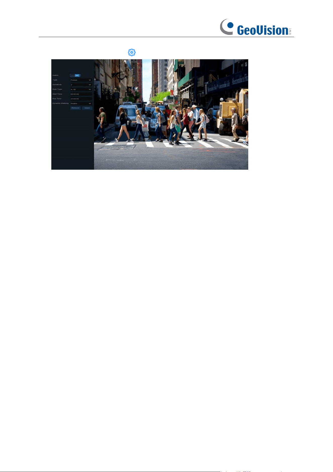
216
4. Click one of the
Setup
icons to configure the detection conditions.
Switch
: Activate or inactivate the detection.
Type: Choose the detection target objects. Motion will detect all moving objects, Person will
detect human beings only, and Vehicle will detect vehicles only.
Sensitivity
: Set the sensitivity level. Level 1 the lowest sensitivity level while level 4 is the highest
sensitivity level.
Rule Type
:
A
→
B:
If a target object is detected moving from side A to side B, the system will count 1 to enter
number; if a target object is detected moving from side B to side A, the system will count 1 to exit
number.
B
→
A:
If a target object is detected moving from side B to side A, the system will count 1 to enter
number; if a target object is detected moving from side A to side B, the system will count 1 to exit
number.
Start Time
: Set the detection start time.
End Time
: Set the detection end time.
Dynamic Marking / Bounding Box: If you enable this option, the border of the detection zone will
be displayed in both live view images and recording files.
Configuration Steps
:
1. Activate the
Switch
.
2. Choose the detection target type.
3. To set the
Sensitivity
.
4. Choose a
Rule Type
.
5. Set the
Start Time
and
End Time
.
6. Use your mouse to click 2 points on the camera picture to draw a virtual line.
7. Click
Save
to save your settings.
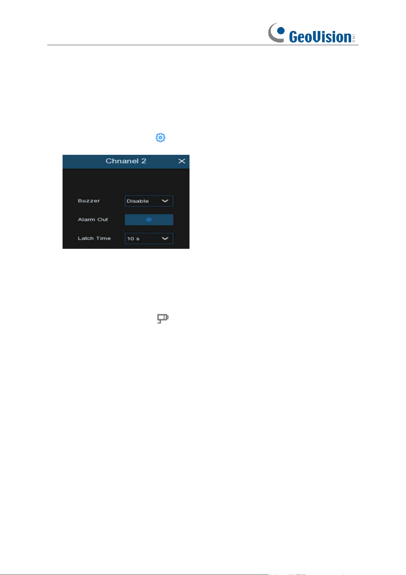
217
8. If you want to modify the position or length of the line, click the red box in the line, the color of
the line will be changed to red color. Click and hold the left button of your mouse to move the
line, or drag the terminals to modify the length or position of the line.
9. If you want to remove one of the lines from the camera picture, click the red box in the line and
then click
Remove
button.
10. Right click your mouse to exit the setup page.
11. Repeat step 3 to finish the configuration for all channels you want to activate the function.
12. Click one of the
Alarm
icons to configure the alarm actions when the Available number is
0.
Buzzer:
Set the buzzer duration in seconds when the Available number is 0.
Alarm Out
: If your NVR supports to connect to external alarm device, you can set to emit an alarm
tone.
Latch Time
: To configure the external alarm time when the Available number is 0.
Right click your mouse to exit the alarm setup page, and then click
Save
button to save the
settings.
13. Click the
Channel View
icon to view the live images & counting data of all activated
channels.
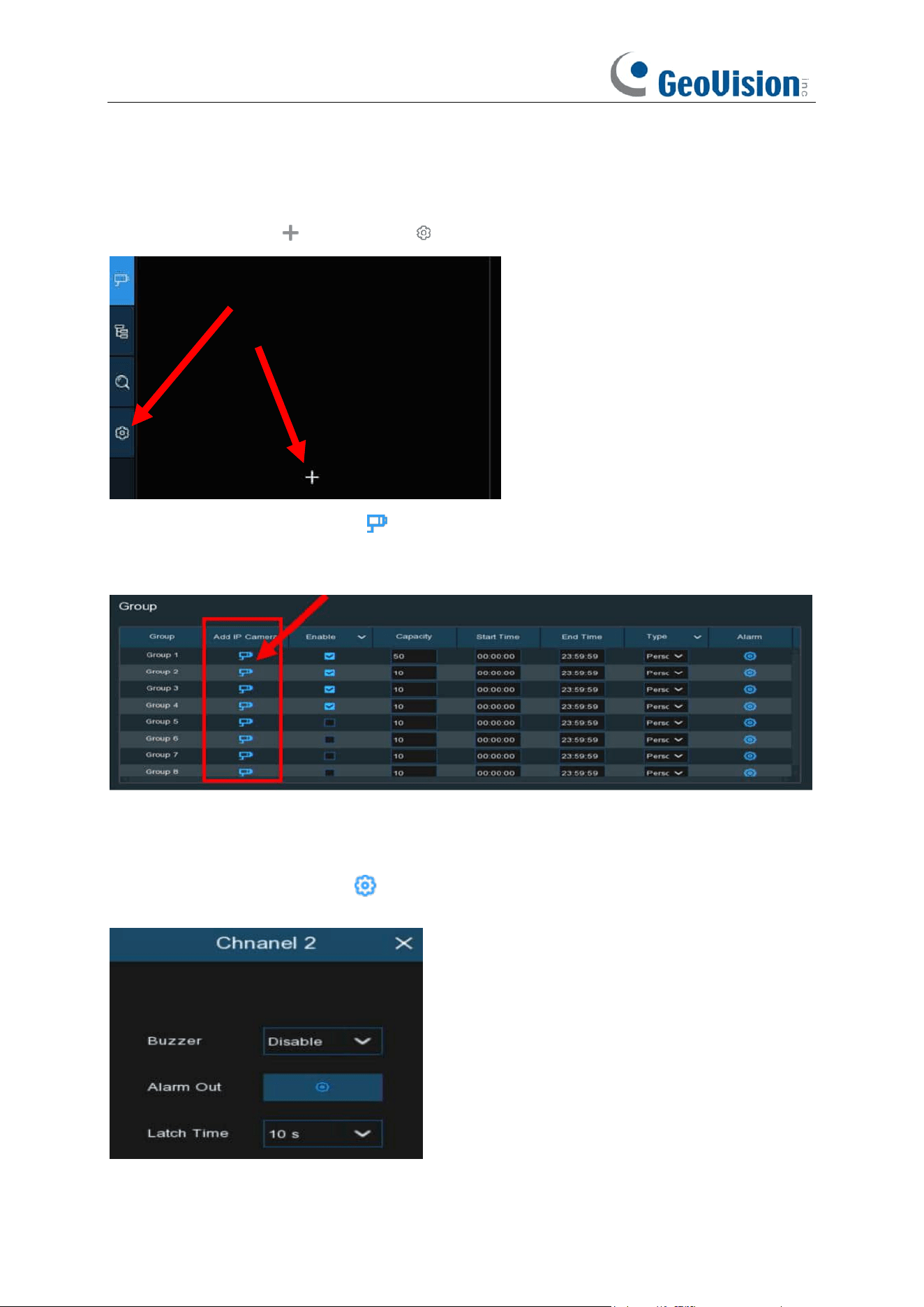
218
6.1.2 Group View Setup
1. Click the add icon or setup icon to get to the configuration page.
2.
Click the
Add IP Camera
icon to add channel(s) to the group. Max. 8 groups can be set,
but each one channel can be added to 1 group only. If a channel is enabled in the Channel
View mode, it will be not allowed to add to any group.
3. Check the Enable box to activate the group.
4. Set the
Capacity
number,
Start Time
,
End Time
of each group.
5. Choose the detection target
Type
from
Person
,
Vehicle
and
Motion
.
6. Click one of the
Alarm
icons to configure the alarm actions when the Available number is
0.
Buzzer:
Set the buzzer duration in seconds when the Available number is 0.
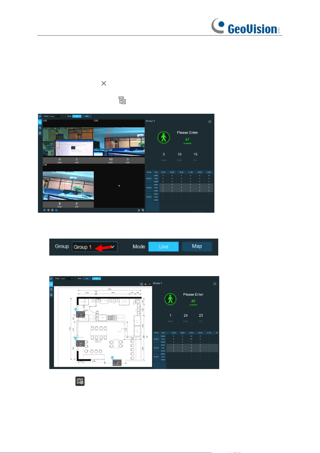
219
Alarm Out
: If your NVR support to connect to external alarm device, you can set to emit an alarm
tone.
Latch Time
: To configure the external alarm time when the Available number is 0.
7. Click the close icon or right click your mouse to go back to previous configuration page,
and then click
Apply
button to save the settings.
8. Click the
Group View
icon to view the live images & counting data of all activated
groups.
9. You can choose which group you want to view the real-time live images and counting
data.
10. Furthermore, it supports to display the counting data in Map mode. Click the
Map
button
to configure the settings.
11. Click the icon to add a map image from your USB memory.
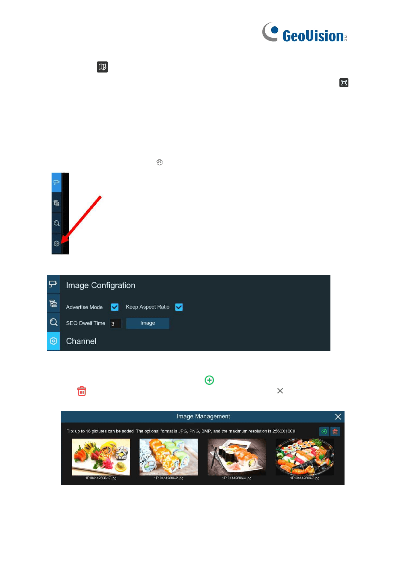
220
12. Click icon to adjust the site of the IP cameras. Click and hold the channel icon and
move one by one to adjust the position of your IP cameras on the map. You can click
icon to display the map in full screen.
6.1.3 Advertise Mode
The system supports to demonstrate your advertising pictures with the Cross Counting functions.
1. Click the
Configuration
icon to in the
Navigation bar
to get to the configuration page.
2. Check the Advertise mode in the
3. Click
Image
button to load advising pictures from your USB memory. It supports to add
maximum 16 pictures with jpg, png and bmp format, and the maximum resolution should be
no more than 2560 x 1600. Click the add icon to add new picture(s) and click delete
icon to delete the added picture one by one. Click the close icon or right click your
mouse to go back to previous configuration page.
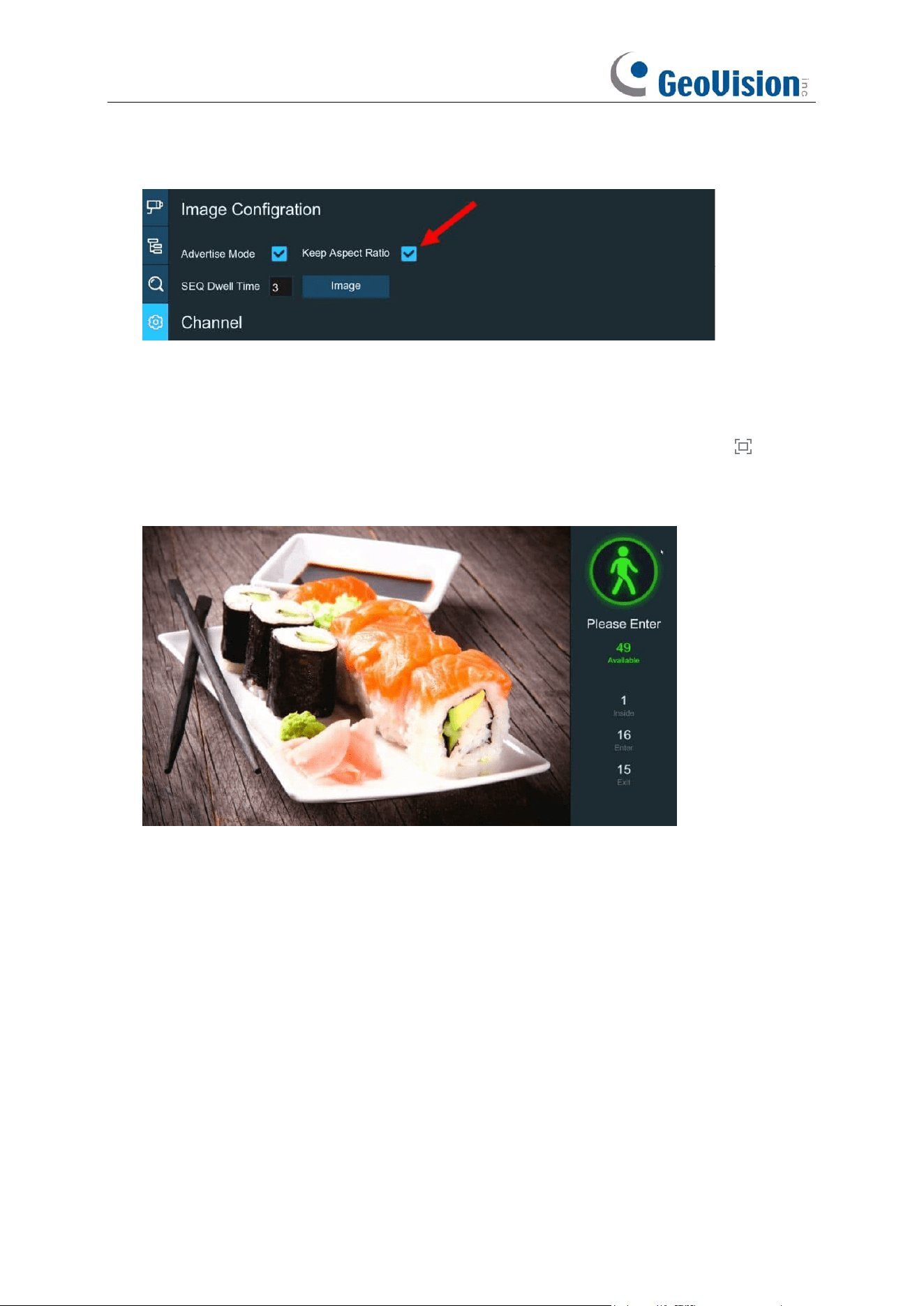
221
4. Check the
Keep Aspect Ratio
box if you want to display the images with their original aspect
ratio. Uncheck the box if you want the pictures to be stretched and displayed full screen.
5. Set the
SEQ Dwell Time
in seconds which will decide how long each picture will stay in the
screen.
6. Click
Apply
button to save your settings.
7. Go back to Channel View mode or Group View mode, click the full screen button on the
right upper corner to display your advertising pictures and the real-time counting data for the
selected channel(s) or group(s).
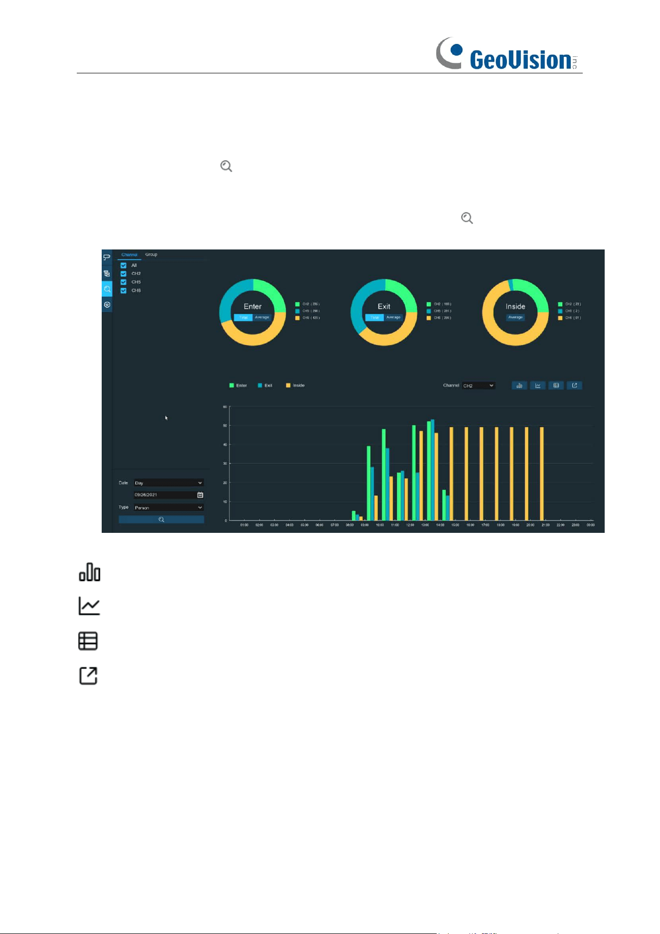
222
6.1.4 Search Counting Data
1. Click the
Search
icon to search the counting data.
2. It allows you to search separately for Channels and Groups. Choose the channel(s) or
group(s) you want to search, set the search duration by day, by week, by month or by year
and choose the target type you want to search. Click the search icon , the result will be
displayed on the right side of the window.
Click to display the result in column chart
Click to display the result in tendency chart
Click to display the result in detail chart
Click to export the result into your USB flash drive
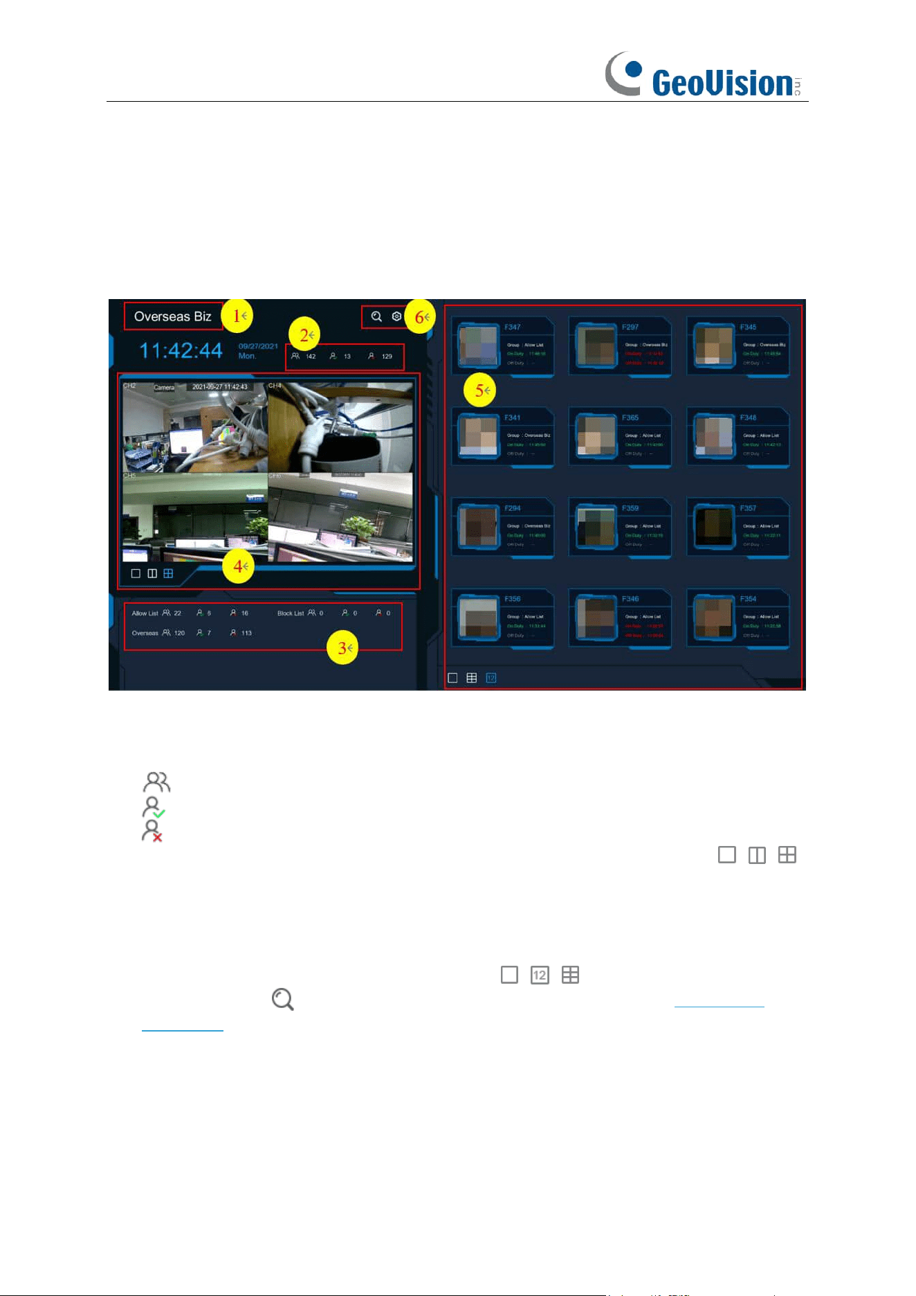
223
6.2 Face Attendance
Face Attendance is an AI application based on Face Recognition results. You’re able to view and
check the real-time statistical data of attendance management visually.
1. Custom title.
2. Overall attendance statistical data of all selected groups.
3. Individual attendance statistical data of each selected group.
The total number of people who need to check attendance
The number of people who have checked attendance already
The number of people who haven’t checked attendance.
4. Live view screen: To display the live camera images. Click the screen split icons , ,
to change the display layout.
5. Push notifications of latest persons who have checked the attendance, including the Name/ID
of the person, captured face image, group, clock in time, and clock out time. Normal clock in &
clock out time will be displayed in green color. Abnormal clock in & clock out time will be
displayed in red color. Click the screen split icons , , to change the display layout.
6. Click search icon to search the face attendance data. Check more on 7.1.9.1 Face
Attendance.
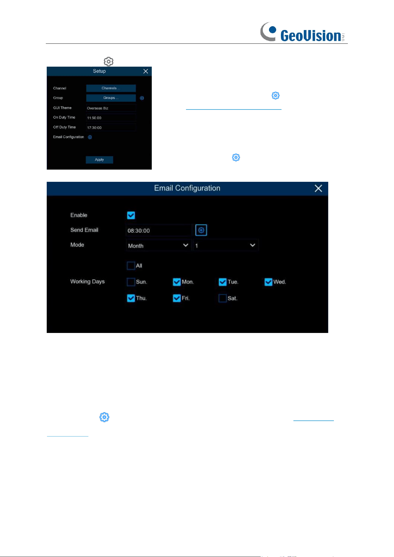
224
Click Setting icon to configure the face attendance settings.
Enable: Check the box if you want to send the attendance statistical data by email.
Send Email: Set the preset time for sending the email.
Mode: Choose to send the email once in every Day, every Week, or every Month.
Day: Send the attendance statistical data of previous day once a day.
Week: Send the attendance statistical data of last 7 days once a week.
Month: Send the attendance statistical data of last month once a month.
Working Days: To select the working days. It will affect the attendance statistical data.
Click the setting icon to configure your email configuration. Check more on 5.5.3.1 Email
Configuration.
Channels: To choose the channels for face detection
Group:
To choose the attendance people group. If you want
to edit the group database, click the icon to edit. Check
more on 5.4.2.2 Database Management.
GUI Theme:
To give a custom title to the face attendance.
On Duty Time:
To set the on-duty time.
Off Duty Time:
To set the off-duty time.
Email Configuration:
To send the attendance statistical
data by email. click the icon to edit the email
configuration.
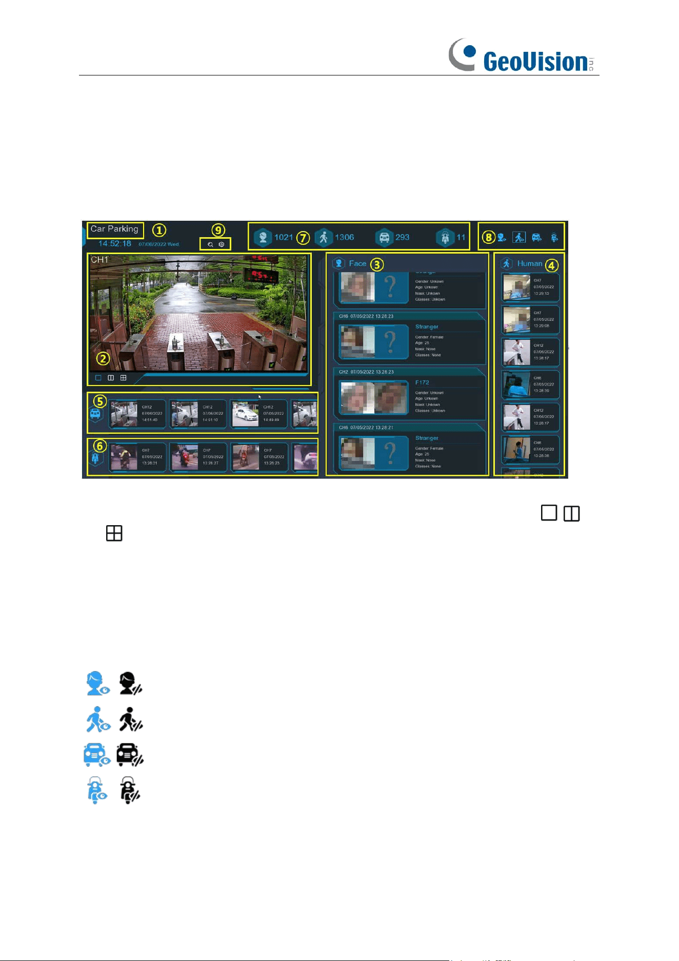
225
6.3. Object Classification
Object Classification is an AI application based on face detection, human and vehicle function,
which is used to classify and count the number of detected faces, human beings, motor vehicles
and non-motor vehicles in a certain period.
1. Customized title of the object classification.
2. Live view screen: to display the live camera images. Click the screen split buttons
to change the display layout. Continuously click a button to display next page.
3. Notifications of detected face images. Use the mouse wheel to move up and down.
4. Notifications of detected human images. Use the mouse wheel to move up and down.
5. Notifications of detected motor vehicles. Use the mouse wheel to move left and right.
6. Notifications of detected non-motor vehicles. Use the mouse wheel to move left and right.
7. Statistical data of detected objects in a selected period.
8. Click the icons to display or hide relative object:
To display or hide face images.
To display or hide human images.
To display or hide motor vehicle images.
To display or hide non-motor vehicle images.
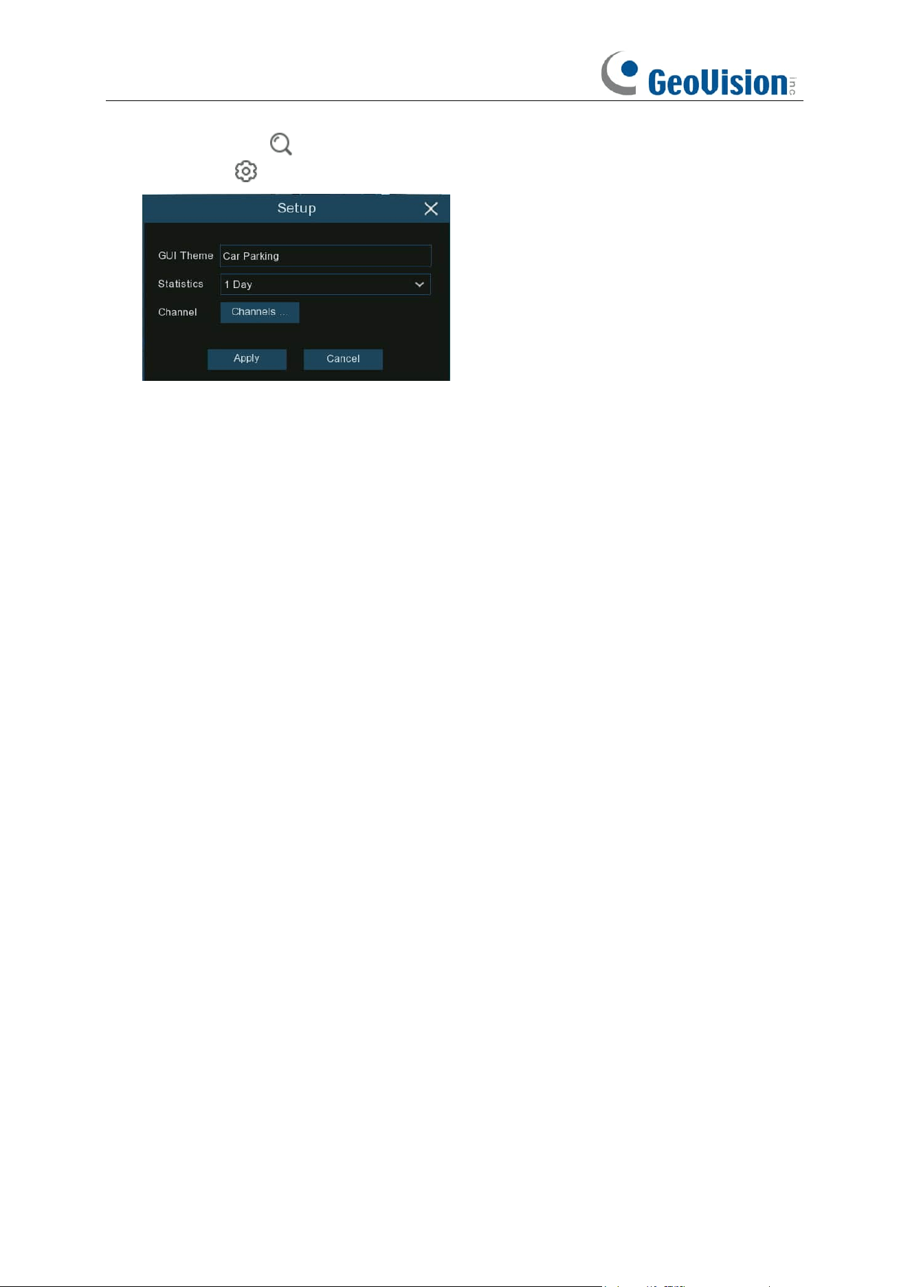
226
9. Click search icon to search the recording of human & vehicle detection events. Click
Setting icon to configure the object classification settings:
GUI Theme: To give a customized title to the object classification.
Statistics: To select the time period you want to show the data.
Channels: Click to choose channel(s) of which you want to show the data.
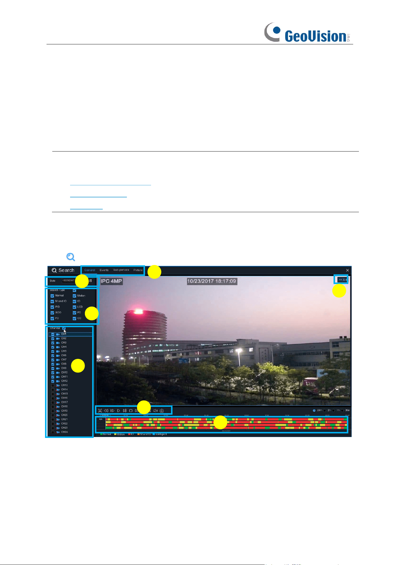
227
Chapter 7 Search, Playback & Backup
The Search function gives you the ability to search for and play previously recorded videos as well
as snapshots that are stored on your NVR’s hard drive. You have the choice of playing video that
matches your recording schedule, manual recordings or motion events only. The Backup function
gives you the ability to save important events (both video and snapshots) to a USB flash drive. A
maximum of 16 channels of playback is supported.
Note:
To play the video clips saved locally on your PC, install and launch one of the following
players
before
locating the recordings. Wait for 3 ~ 30 seconds before the video starts to play.
1. GV-R Series Video Player
2. VLC Media Player
3. KM Player
7.1 Using Search Function
Click
Search
button in the Start Menu to enter search section.
1.
Search Options:
the system provides various search & playback methods: General, Events,
Sub-periods, Smart & Pictures
2.
Search Date:
search by a date to play back.
3.
Search Type:
the system provides different search types to narrow your search.
4.
Channel Selection:
to choose the channels you want to search & play.
5.
Video Playback Controls:
to control the video playback.
1
2
3
4
5
6
7
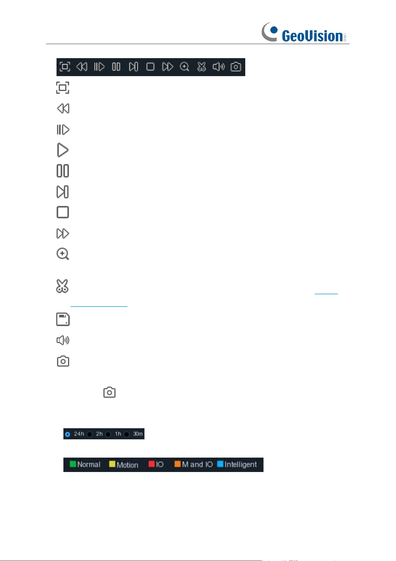
228
Enlarge the video playback to full screen
Rewind, x2, x4, x8 and x16
Slow Play, 1/2, 1/4 and 1/8, 1/16 speed
Play
Pause
Play frame by frame. Click once to play a frame of the video
Stop
Fast Forward, x2, x4, x8 and x16
Digital Zoom: Click to zoom in then click-and-drag on a camera image during playback to
zoom in on the selected area. Right-click to return to regular playback.
Video Clip. Quickly save a section of video to a USB flash drive. View more on 7.1.1.1
Video Clip Backup
Save Video Clip.
Volume Control
: scroll the slider bar to increase or decrease volume.
Snapshots: to capture a snapshot image to your USB flash drive. If the video playback is
in split-screen view, move the mouse cursor to the channel you want to capture, and then
click the icon to save the snapshot.
6.
Timeline:
Continuous recordings are shown with colored bars to represent different types of
recording (legend shown in the bottom-right corner of the display). Use the timeframe options
( ) to view a smaller or larger time period.
Different types of recording shown in different colors:
Continuous Recording in
Green
color;
Motion Recording in
Yellow
color;
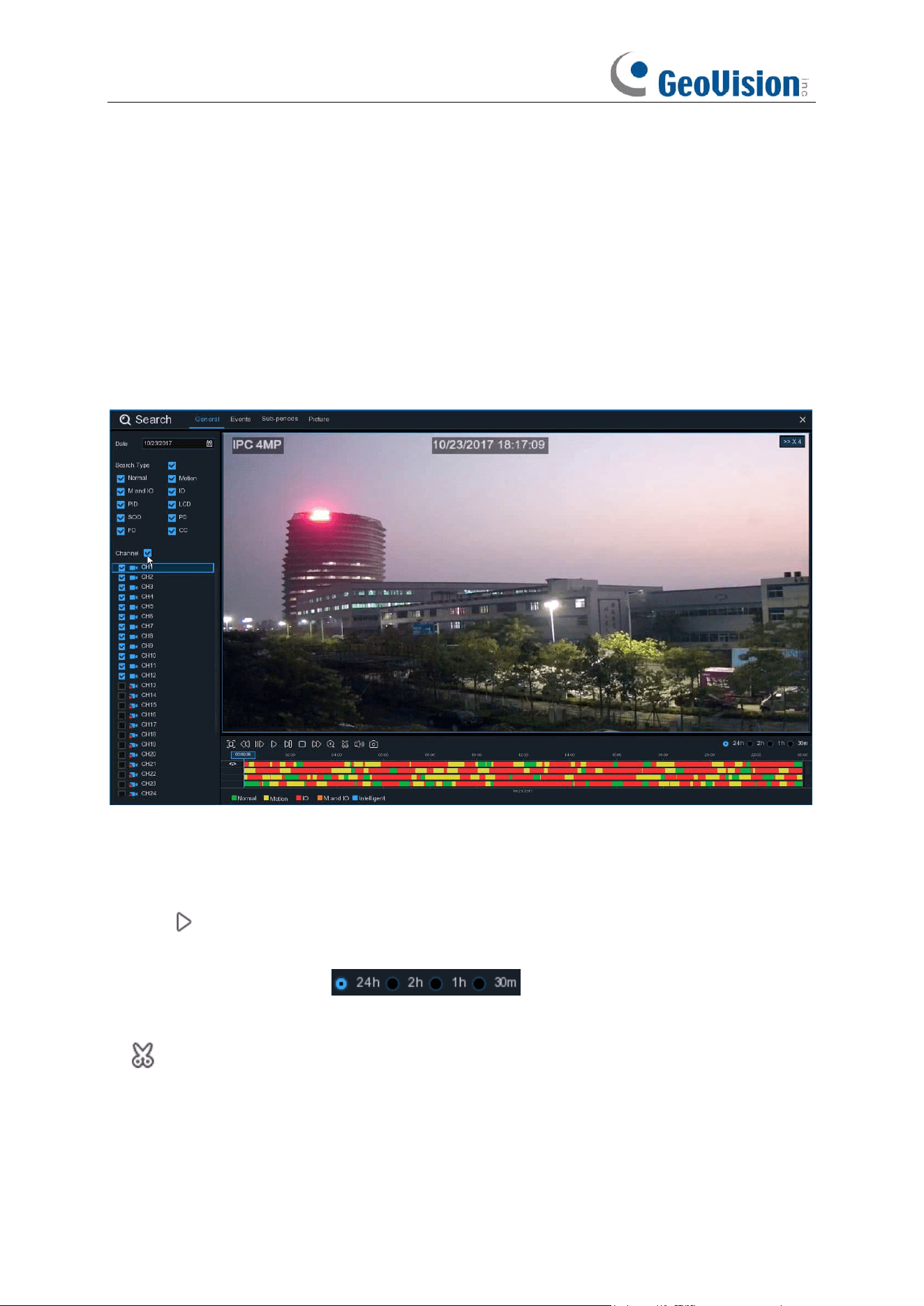
229
I/O Recording in
Red
color;
Motion & I/O Recording in
Orange
color;
AI / Intelligent Recording in
Blue
color;
7.
Playback Status:
display the video play status.
7.1.1 Search & Play Video in General
This menu gives an option to search & play recording for a selected date.
1. Select a date to search for video recording from the calendar.
2. Choose a search type.
3. Check channels you would like to search, or check
Channel
to search all connected channels.
4. The search result will display on the timeline from 00:00 to 24:00.
5. Click button to start playback.
6. Control the playback with buttons on
Video Playback Controls.
7. Use the timeframe options ( ) to view a smaller or larger time period.
8. If you want to quickly save a section of video during playing back to a USB flash drive, use the
Video Clip
backup
function.
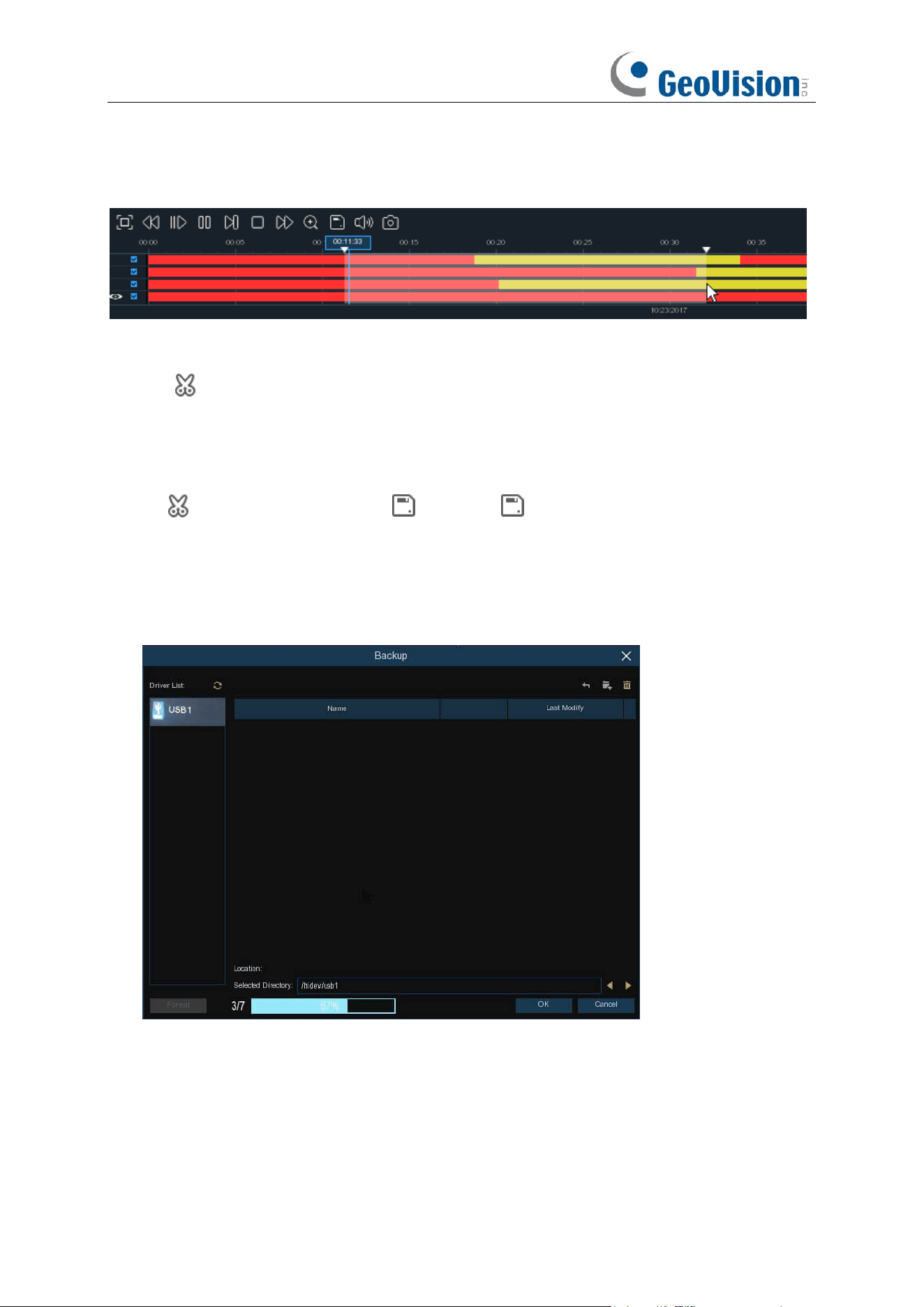
230
7.1.1.1 Video Clip Backup
1. Insert your USB flash drive to the NVR.
2. Start a video recording playback.
3. Click icon.
4. Check the channel(s) you want to make a video clip backup.
5. Move the mouse cursor to the timeline where you want to start the video clip.
6. Press and hold the left button of your mouse, and drag the drag the cursor to the timeline where
you want to end the video clip.
7. The icon has been changed to icon, click to save the video clip.
8. Select a file type for your backup files, click
Save
button to save the video clips. Make sure your
USB driver has enough space to save the video clips.
The backup drive menu appears. Navigate to the folder you want the backup files to save in.
9. Click
OK
to begin. The progress bar at the bottom of the window shows you the progress of the
backup.
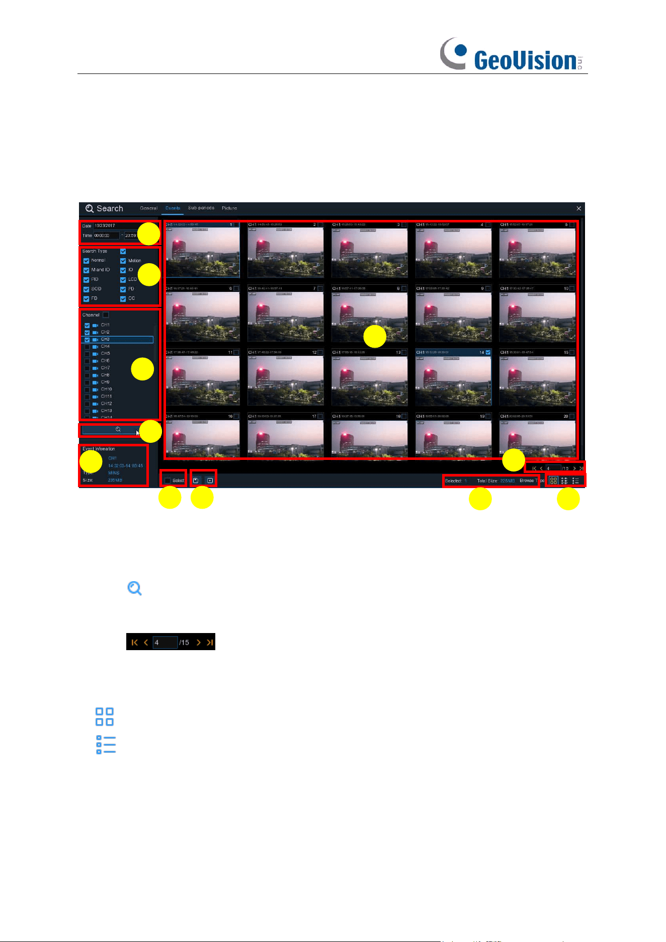
231
7.1.2 Event Search, Playback & Backup
Event search lets you view a list of video recordings with the channel, start and end time, and
recording type conveniently summarized. You can also quickly back up events to a USB flash
drive.
To search, play & back up for events:
1. Choose the date & time you want to search.
2. Check the recording types you want to search, or check Search Type to choose all.
3. Choose the channels you want to search, or check Channel to choose all channels.
4. Click icon to start search.
5. Events fitting your search criteria are displayed in list form. You can double click the left button
of your mouse upon one of the events to play the video immediately.
6. Click icons in the bottom-right corner of the menu to browse between pages
of events, or input the page you want to browse.
7. You can switch the view of list form in by clicking below icons which is show at the right bottom
corner of the screen:
Thumbnails view.
You can view the snapshots of the events.
List view.
The events will be displayed in list.
2
10
1
3
4
5
6
7
8
9
11
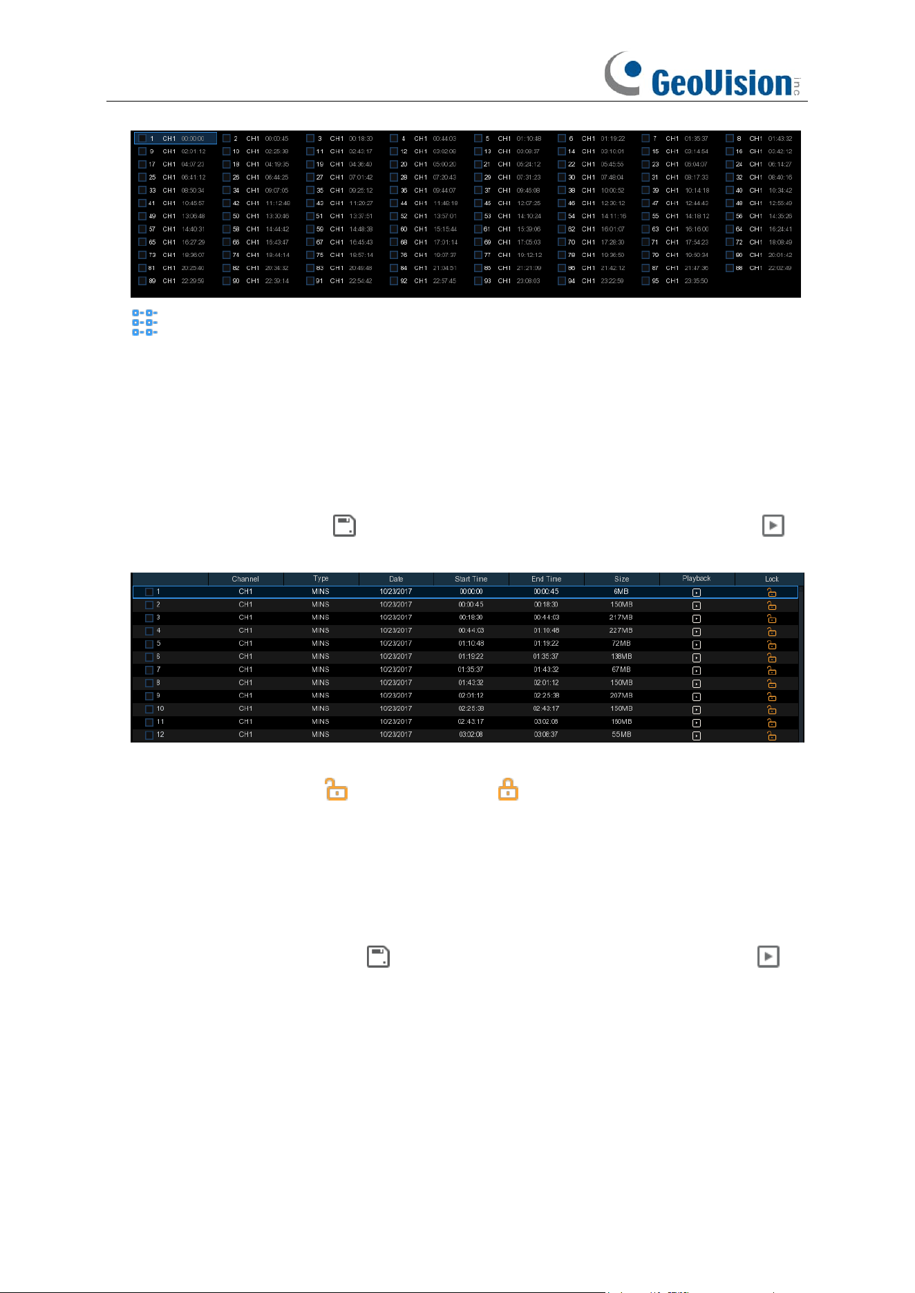
232
Detailed view.
You can view the details of the events.
8. When you click the left mouse button on one of the video clips, the system displays the event
video clip information in the lower left corner of the screen.
9. Check the checkbox to sort the files in a descending order.
10. Check the checkbox after the event number to select a file, or check the checkbox after the
event number to select all video clips on the page.
11. The number of files selected and the total size information will be displayed in the lower right
corner of the screen.
12. After selecting "File", click the icon to save the picture to a USB flash drive, or click
the icon to play the video clips.
In the detailed view mode, you can lock the video events to keep events from being overwritten
in the hard drive. Click the icon to lock or click to unlock the events.
1. When you click the left button of your mouse upon one of the event, system will show the
event information on the left bottom corner of the screen.
2. Check the box next the number of the event to select files, or check the box next
Select
to
select all events in the page.
3. The number of selected files, total size information will be displayed at the right bottom of the
screen.
4. After selecting file, you can click icon to save the video to USB flash drive. Or click
icon into event playback control window to play the video.
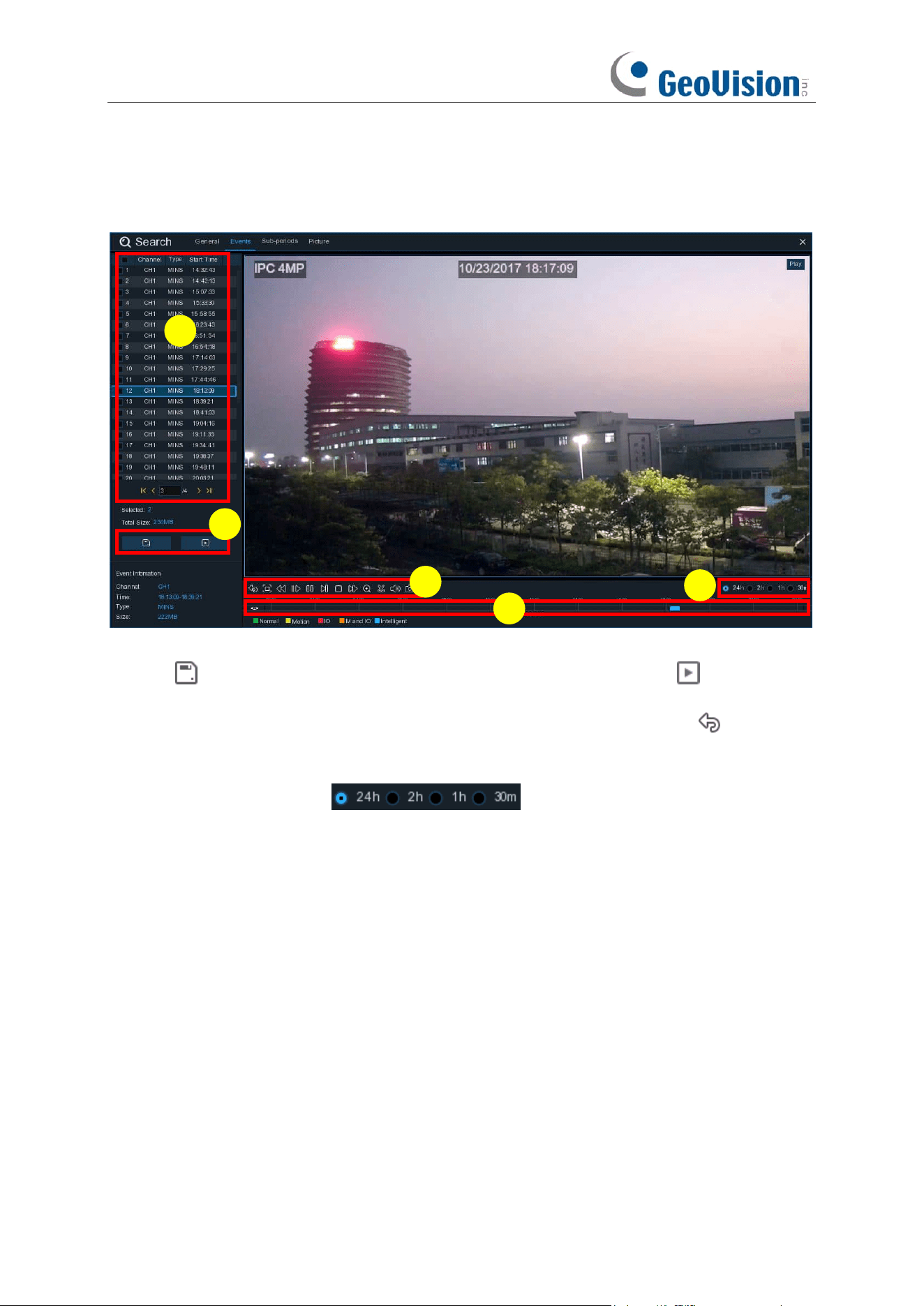
233
7.1.2.1 Event Playback Control
1. Event List, you can select the events here.
2. Click icon to save your selected event videos to USB flash drive. Click icon to play
video.
3. Control the playback with buttons on
Video Playback Controls.
You can click icon or click
right button of your mouse to exit the playback and return to event search window.
4. The event you are playing now will be displayed on the timeline.
5. Use the timeframe options ( ) to view a smaller or larger time period.
4
3
1
2
5
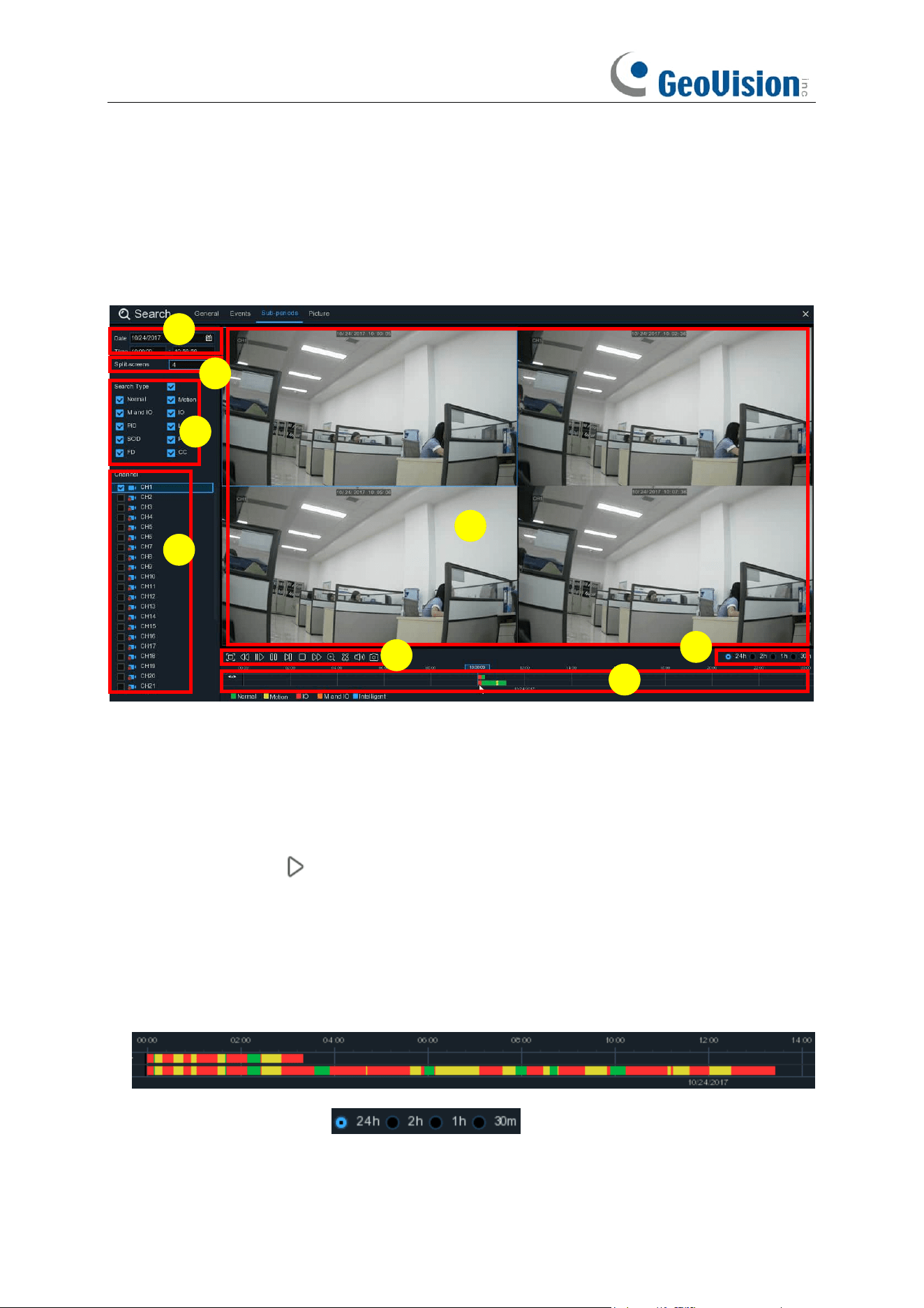
234
7.1.3 Sub-periods Playback
Sub-periods playback allows you to play multiple normal recordings and motion events
simultaneously from a single channel. With normal and event recordings, the video is divided
evenly depending on the split-screen mode that has been selected. For example, if the video is an
hour long and you have selected Split-screens x 4, each split-screen will play for 15 minutes.
To search & play video in sub-periods:
1. Choose the date & time you want to search.
2. Choose the split-screens you want the videos to be played in.
3. Check the recording types you want to search, or check Search Type to choose all.
4. Choose the channels you want to search. Note that this function only supports to search & play
one channel at a time.
5. Click the play button to start playing. Control the playback with buttons on
Video Playback
Controls.
6. Videos are being played in split-screens.
7. Click the left button of your mouse upon a particular split-screen, the time period of the video
split-screen will be displayed on the timeline. The color bar on the top of the timeline indicates
the time span of the video split-screen you have clicked. The color bar on the bottom of the
timeline indicates the time span for the whole videos you have searched.
8. Use the timeframe options ( ) to view a smaller or larger time period.
6
8
1
3
7
5
4
2
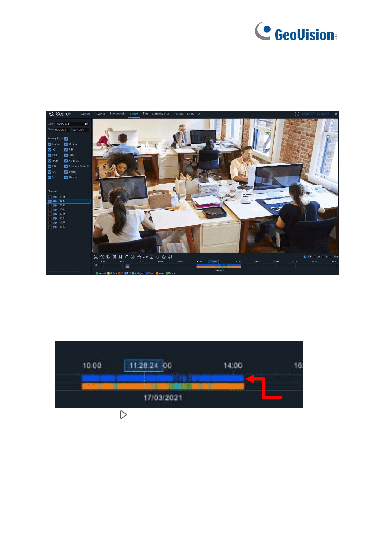
235
7.1.4 Smart Search
With Smart search function, you will be able to quickly search and play the motion recording
videos which were triggered by human beings.
To search & play video in Smart Search:
1. Choose the date & time you want to search.
2. Check the recording types you want to search, or check Search Type to choose all.
3. Choose the channel you want to search. Smart Search supports to search & play one channel
only at a time.
4. The Smart Search result will be displayed in the time slot in blue color.
5. Click the play button to start playing. Control the playback with buttons on
Playback
Controls.
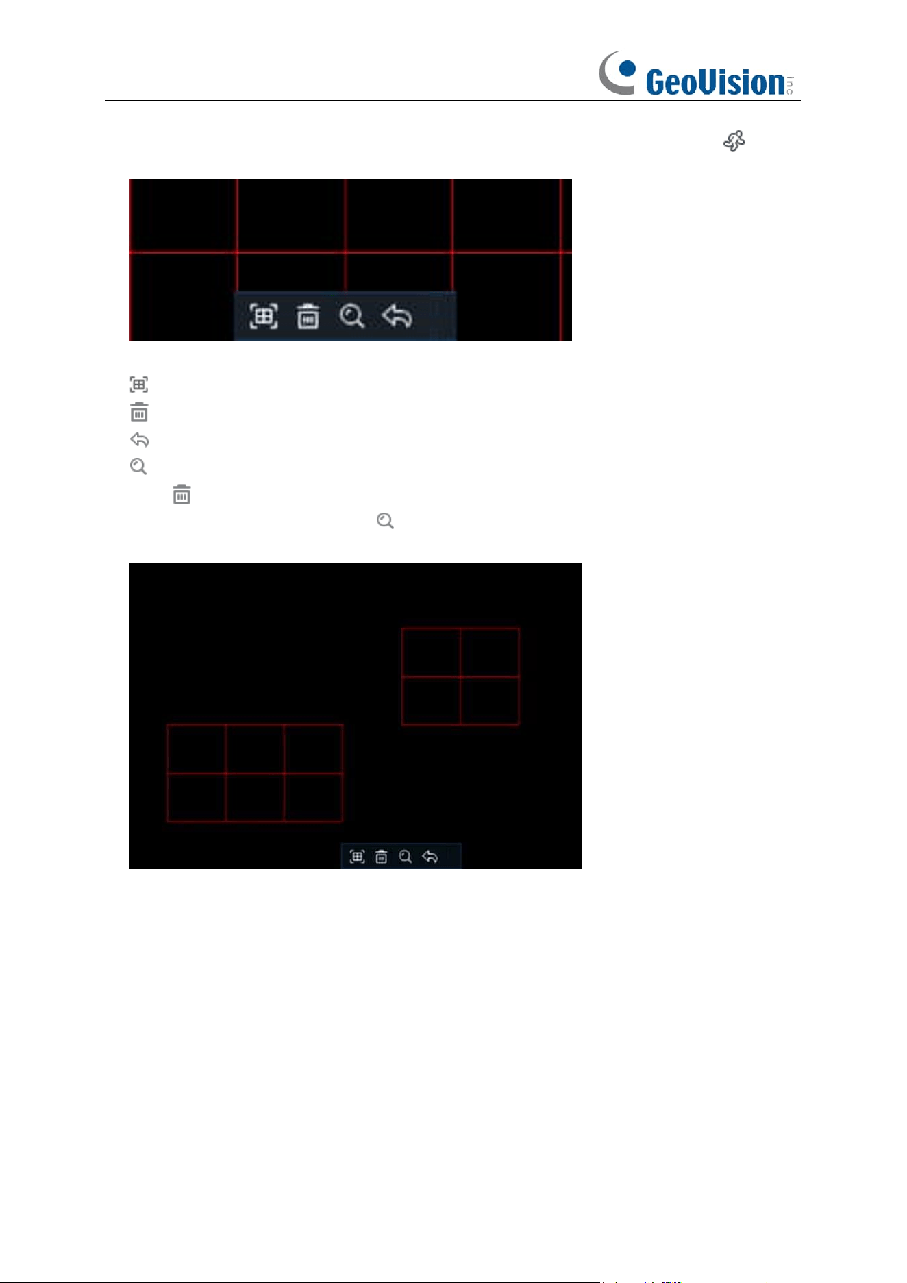
236
6. It supports to narrow the search by selecting a certain area in the images. Click the icon
on the
Playback Controls
bar, the aera selection page will be displayed.
The selected aera will be marked with red grids.
: select whole image.
: clear your selection.
: go back to playback interface.
: search.
Click button to clear all selection, and then use your mouse to select the certain areas you
want to search in the image. Click button, the system will search the display the smart
search result for the selected areas.
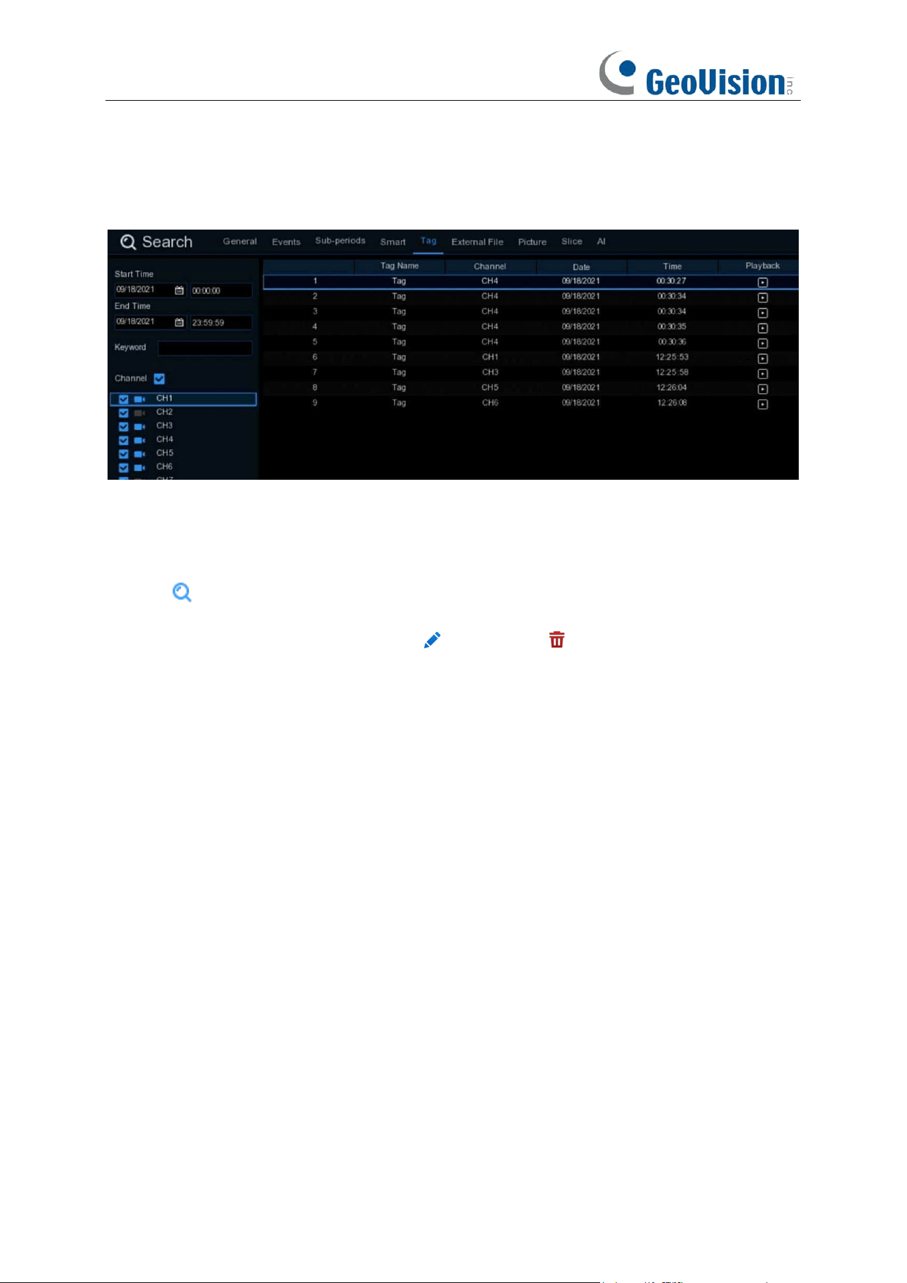
237
7.1.5 Tag Search
You can search, play and manage the contents with tags you added in live view and/or playback.
1. Select the start time and end time you want to search.
2. Select the channel(s) you want to search.
3. If you gave customized tag names to the tags, you can input the keyword to narrow your
search.
4. Click button to search. The tags will be displayed on the right window. Click the play button
to start playing.
5. If you want to modify the tag name, click button. Click button to delete the tag.
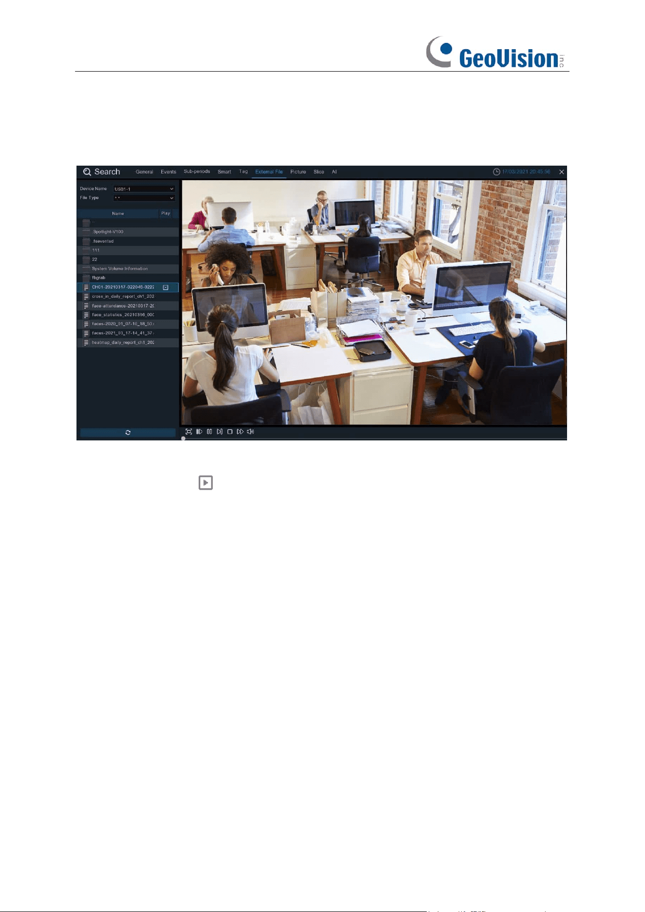
238
7.1.6 Play External File
The NVR supports to play the videos saved in the external USB memories.
Insert your USB memory into the USB port, find out the folder where the video files are saved, and
then click the play icon to play the video.
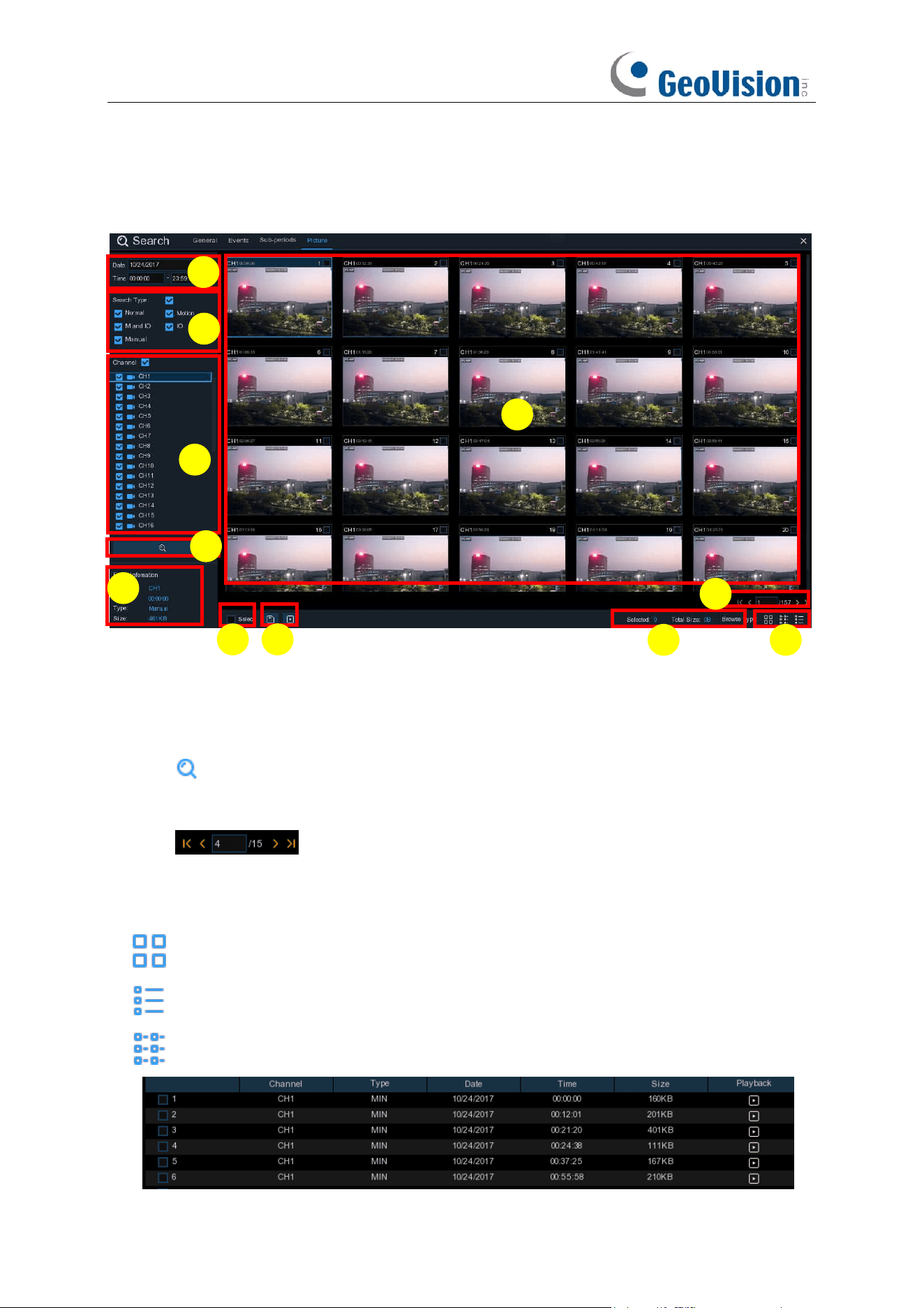
239
7.1.7 Picture Search & View
This function can be used to search, play and copy snapshots to a USB flash drive.
To search, play & back up pictures:
1. Choose the date & time you want to search.
2. Check the picture capture types you want to search, or check Search Type to choose all.
3. Choose the channels you want to search, or check Channel to choose all channels.
4. Click button to start search.
5. Pictures fitting your search criteria are displayed in list form. You can double click one of the
pictures to get a larger view.
6. Click icons in the bottom-right corner of the menu to browse between pages
of pictures, or input the page you want to browse.
7. You can switch the view of list form in by clicking below icons which is show at the right bottom
corner of the screen:
Thumbnails view. You can view the snapshots of the events.
List view. The events will be displayed in list.
Detailed view. You can view the details of the events.
2
10
1
3
4
5
6
7
8
9
11
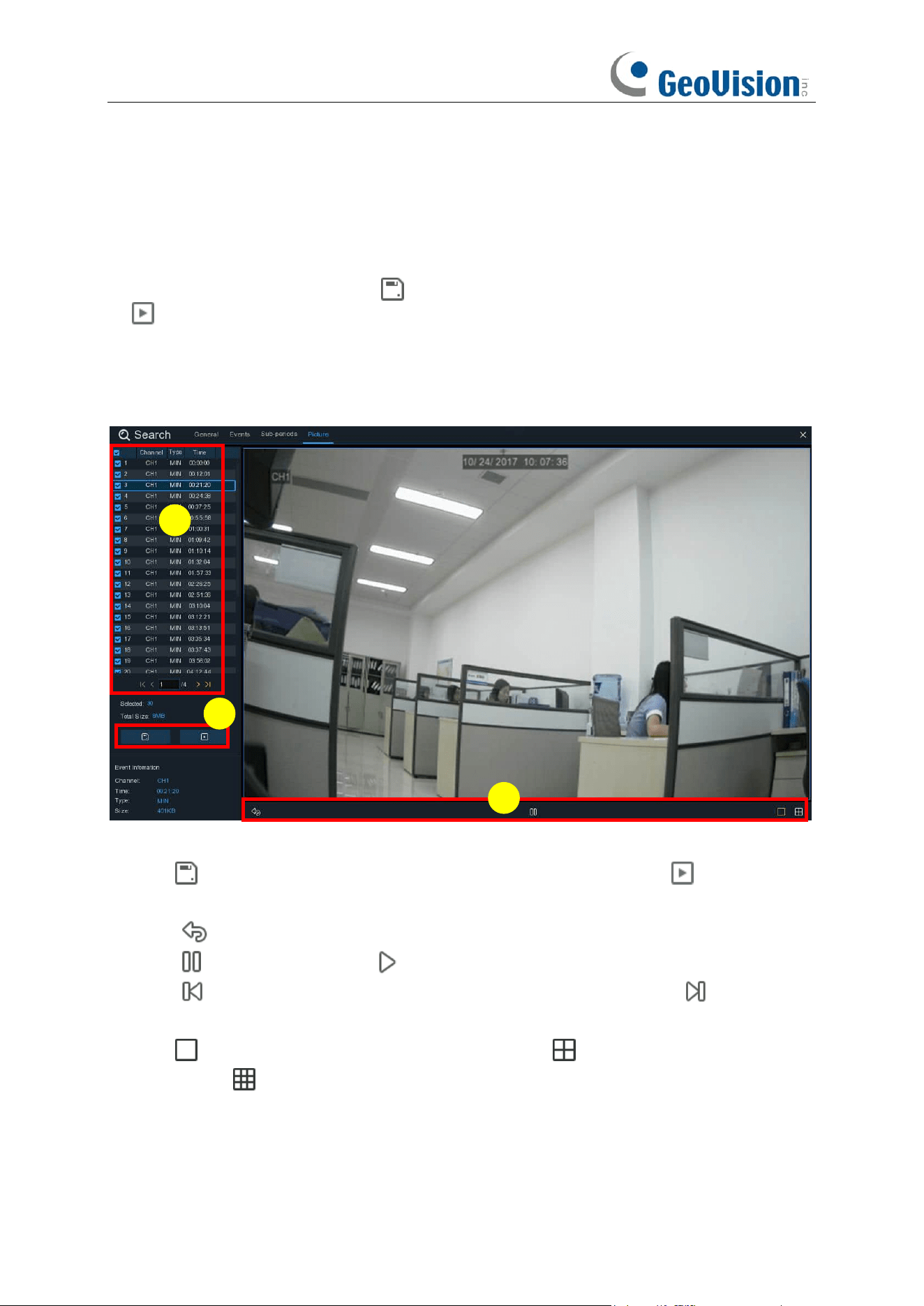
240
8. When you click the left button of your mouse upon one of the pictures, system will show the
picture information on the left bottom corner of the screen.
9. Check the box next the number of the event to select files, or check the box next
Select
to
select all pictures in the page.
10. The number of selected files, total size information will be displayed at the right bottom of the
screen.
11. After selecting file, you can click button to save the pictures to USB flash drive. Or click
button to go into picture preview control window.
7.1.7.1 Picture Preview Control
1. Picture List, you can select the pictures here.
2. Click button to save your selected pictures to a USB flash drive. Click button to view
the pictures in slideshow.
3. Press button to exit preview control window and go back to picture search window.
Press button to pause, press to resume slideshow.
Press button to display previous snapshot or group of snapshots, press to display the
next snapshot or group of snapshots.
Click button to view a single snapshot at a time, click button to view four snapshots at
a time, press buttons to view nine snapshots at a time.
3
1
2
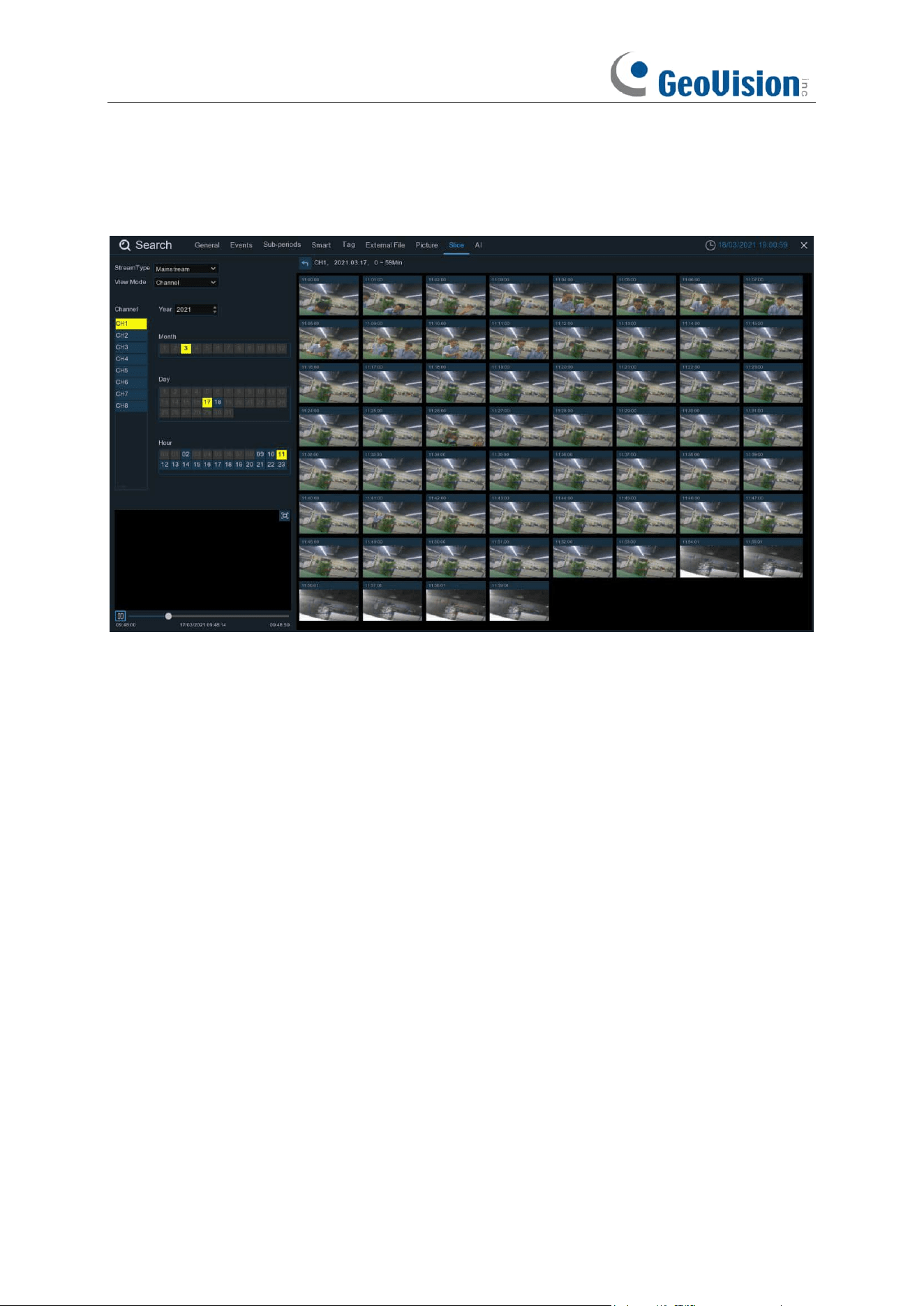
241
7.1.8 Slice Search
This is a function to slice each hour’s video into 60 fragments.
Choose the video stream type, channel, date, and hour. The system will display 60 thumbnail
images of each minute on the screen. Click on any one of the thumbnail images, the video will be
played on the left bottom corner.
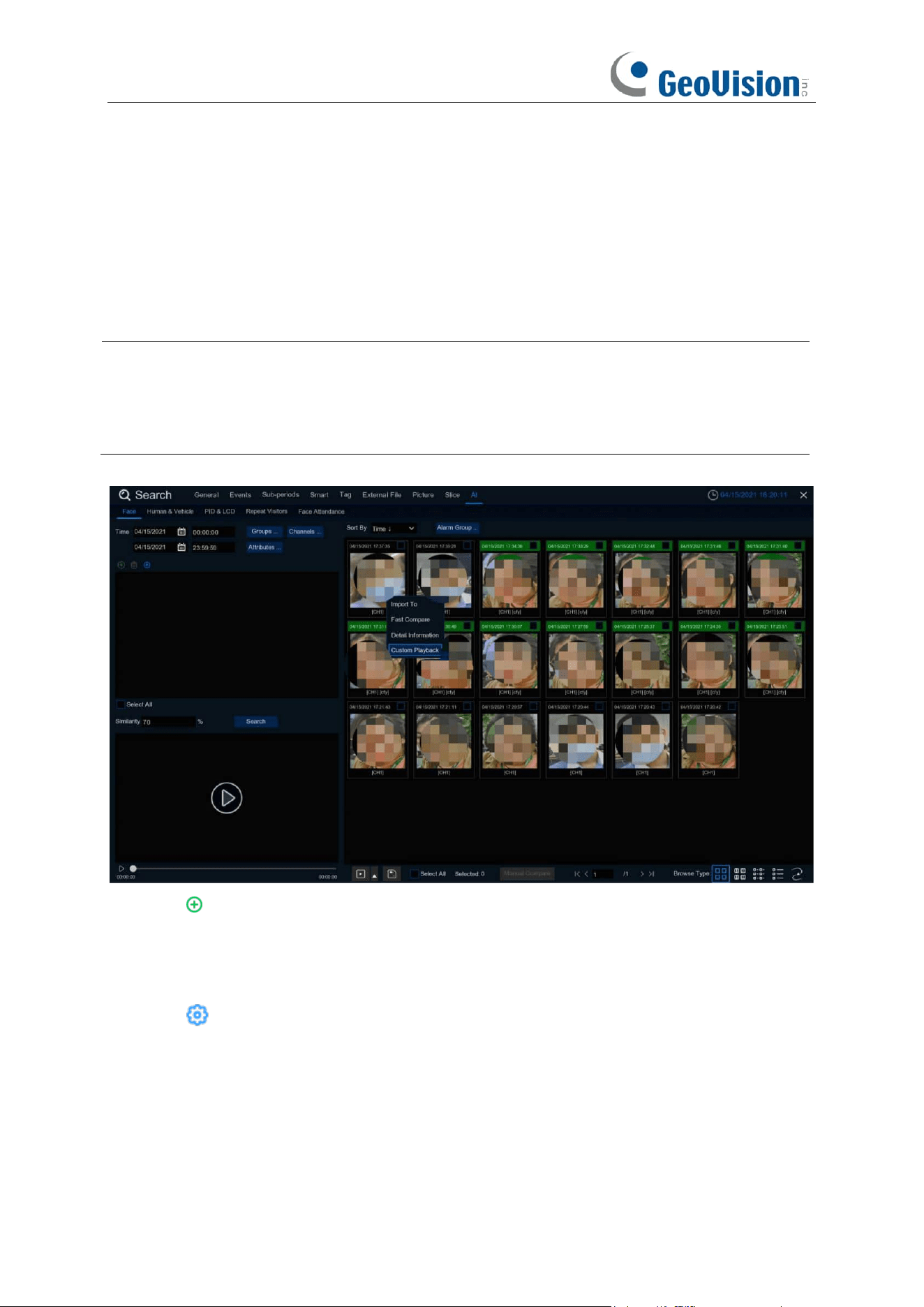
242
7.1.9 AI Search
7.1.9.1 Face Search
Choose date, time, channel, groups to search all captured faces.
Note:
The Face Search and Tracking functions are based on Face Detection and/or Face
Recognition results. See 5.4.1.1 FD (Face Detection) and 5.4.2 Face Recognition. Make sure
Face Attribute
is enabled in
Face Detection
before you can use facial features to find search
results.
1. Click icon to add customized faces.
2. Choose the
Channels
you want to search.
3. You can also set search conditions of the facial features in
Attributes
.
4. Choose the Face Recognition group in
Alarm Groups
.
5. Click icon to configure the AI settings.
6. Click
Search.
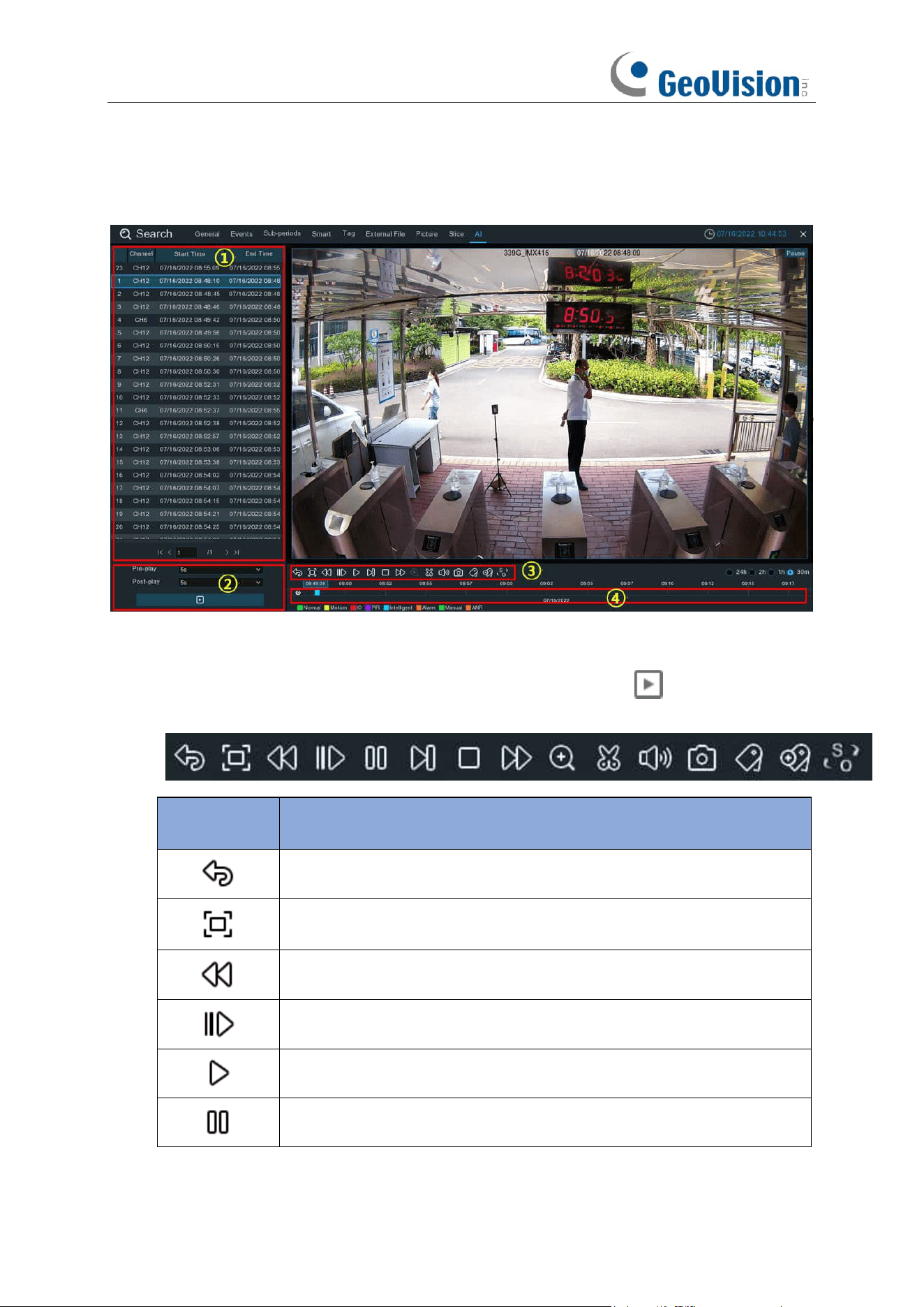
243
7.1.9.1.1. Playing Events
1. Event List.
Use the arrow buttons to turn page or use the keypad to navigate to a specific
page. Double-click on an event to play it directly.
2. You can add time duration before and after the event and then click button to play.
3.
Video Playback Controls:
to control the video playback.
Button
Function
Return to event search page
Enlarge the video playback to full screen
Rewind button, subsequent presses of the button will change the rewind
speed.
Slow Play, subsequent presses of the button will change the play speed
Play in normal speed
Pause
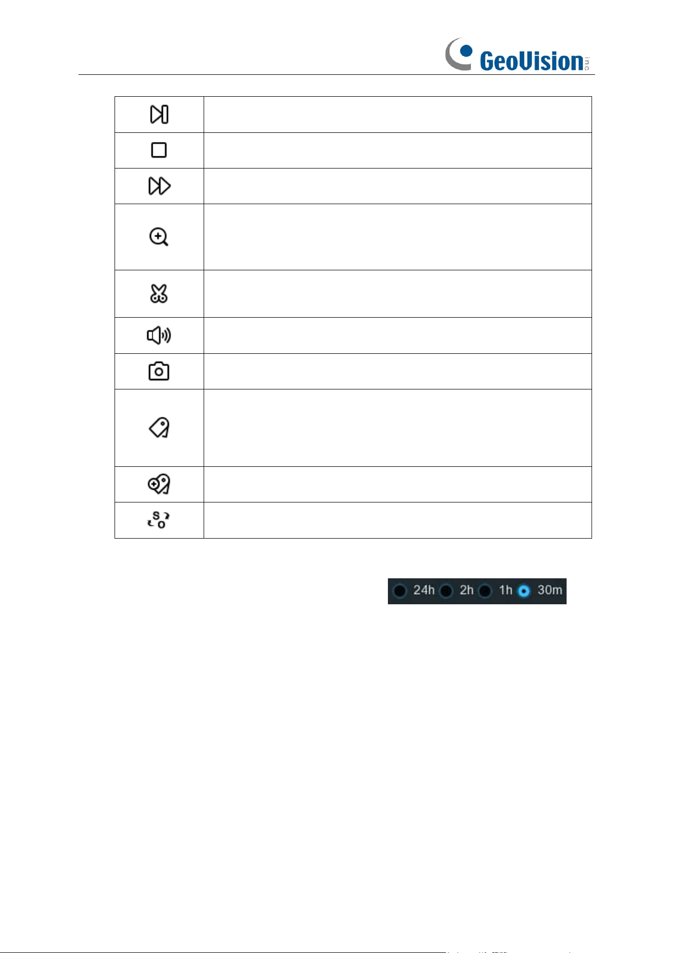
244
Play frame by frame. Click once to play a frame of the video
Stop playing
Fast forward button, subsequent presses of the button will change the
speed.
Select a camera, click this button then use the scroll button on the
mouse to zoom. Use the picture-in-picture screen to select a different
area to view. Right-click to exit.
This button allows you to edit the video by setting mark in and mark out
points which you can then copy to a USB flash drive.
Click to adjust audio output volume
Click to take a snapshot and save to your USB flash drive
Tagging allows you to record information such as a person or object
within the video. Click on a camera to select, pause the video when you
see a person or object to be tagged, then press this button (multiple
tags can be created).
Same as above, but you can name the tag.
Click to switch the image scale for all playing cameras between original
and stretch.
4.
Timeline:
Quick locate the playback position by clicking on the time line.
You can zoom in or
zoom out the timeline by using the timeframe options for
precise location.
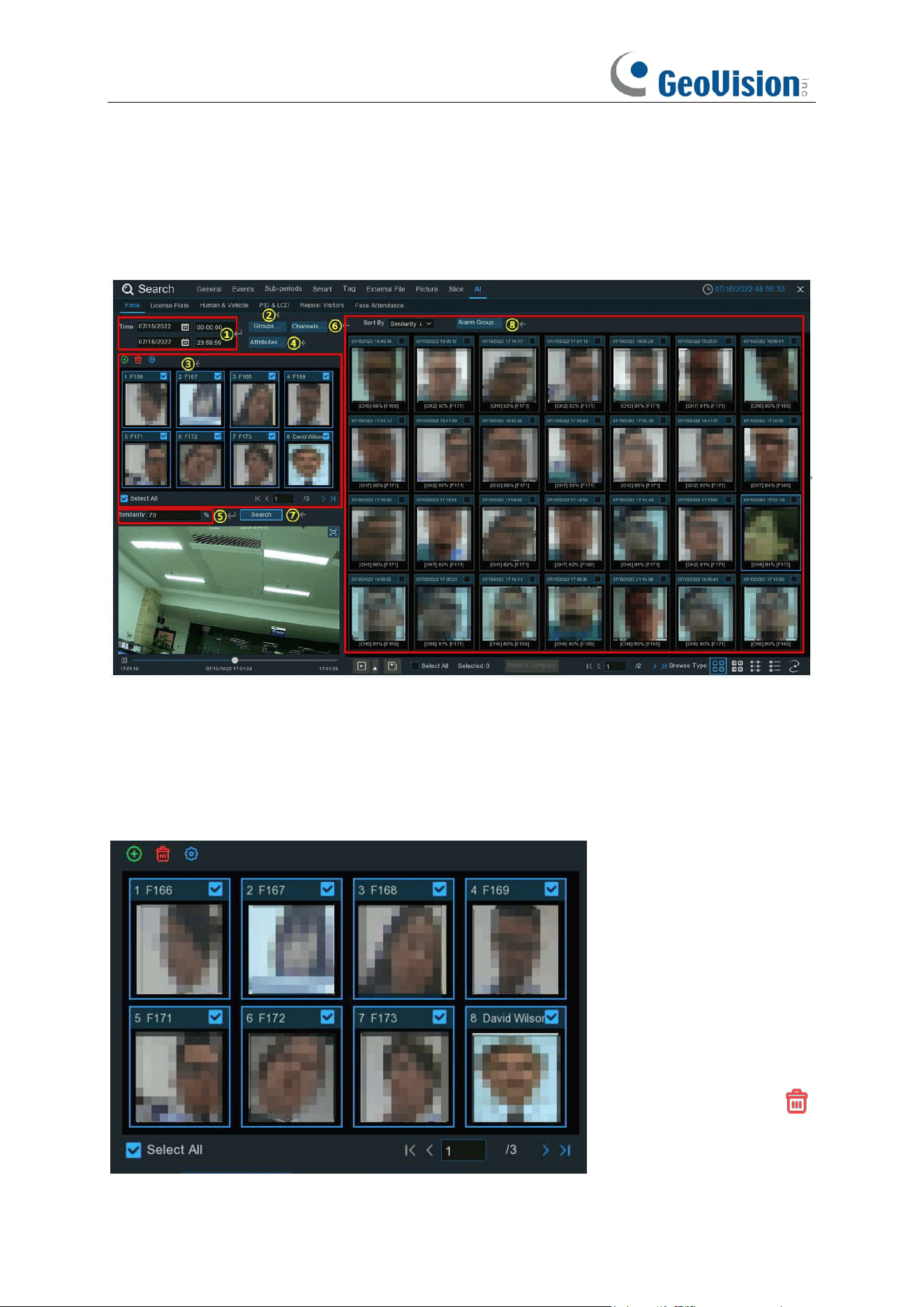
245
7.1.9.1.2. Search & Compare Face Images (Recognition)
You can appoint one or more face profiles selected from face recognition data base and then
search, the system will compare and display the face images that match your search criteria.
1. Click the calendar icon to select a date to search on. A red underline on a date indicates
snapshots were taken on those particular dates. For time, you can search over 24 hours or
you can use the keypad to enter a specific start and end time
2. Click Groups button, and then select the groups where your targeted face profiles are saved
in.
3. All face profiles exist in your selected group(s) will be displayed in the display window:
All face profiles are selected
by default. You can untick the
checkbox of "Select All" to
deselect all.
Tick or untick the checkbox
above each image to select
or deselect it.
If you want to delete a face
profile, click on the image,
and then click the button .
If you want to add more

246
targeted face images, click add button , and then select face images from internal or external
storage device.
4. If you have enabled the Face Attributes detection (5.4.1.1 FD (Face Detection)), you can click
here to appoint the attribute(s) you want to search.
5. Set the Similarity: Set how closely, in percentage terms, the detected face must match a
targeted face to be considered a recognized match. The default threshold is 70%. A higher
similarity % will result in fewer false recognition results.
6. The system searches all channels by default. You can click the "
Channels
" button to select
specific channel(s) that you want to search for.
7. Click
Search
button to commence a search.
8. The face images that match your search criteria will be displayed. You can narrow your
search by selecting specific alarm group(s).
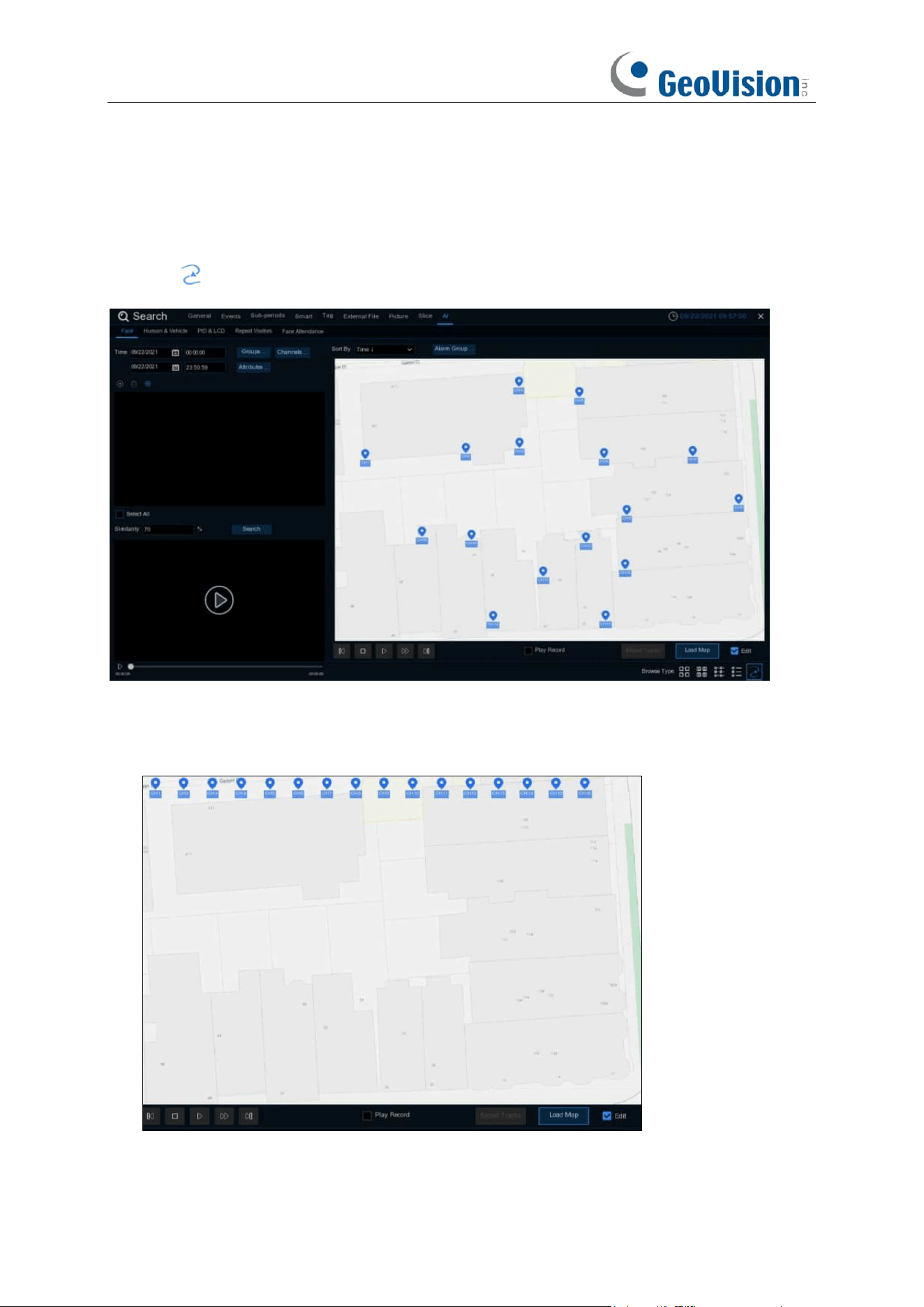
247
7.1.9.1.3 Face Tracking on E-Map
E-Map function helps track a person’s faces.
Click the icon to set the E-Map function.
1. Click Load Map button to load a map image from your USB memory.
2. Check the Edit box. Click and hold the channel icon and move one by one to adjust the site of
your IP cameras on the map. Uncheck the Edit box to quit the edition.
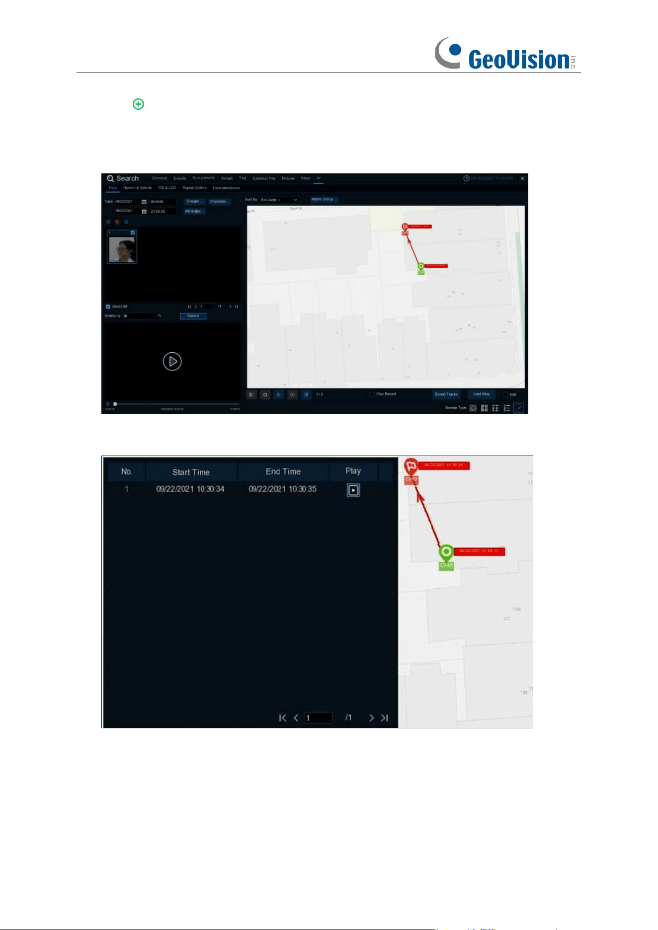
248
3. Click icon to select one face image from local storage or external USB storage. Select
date & time, group(s), channel(s), set the similarity rate, and then click
Search
button. The
system will display the result on the e-map. If the person was captured by multiple cameras,
the system will display his/her moving track on the map.
4. Click one of the sites on the map, it will display the captured date & time. Click the
Play
button,
the recorded video will be played in the left bottom corner.
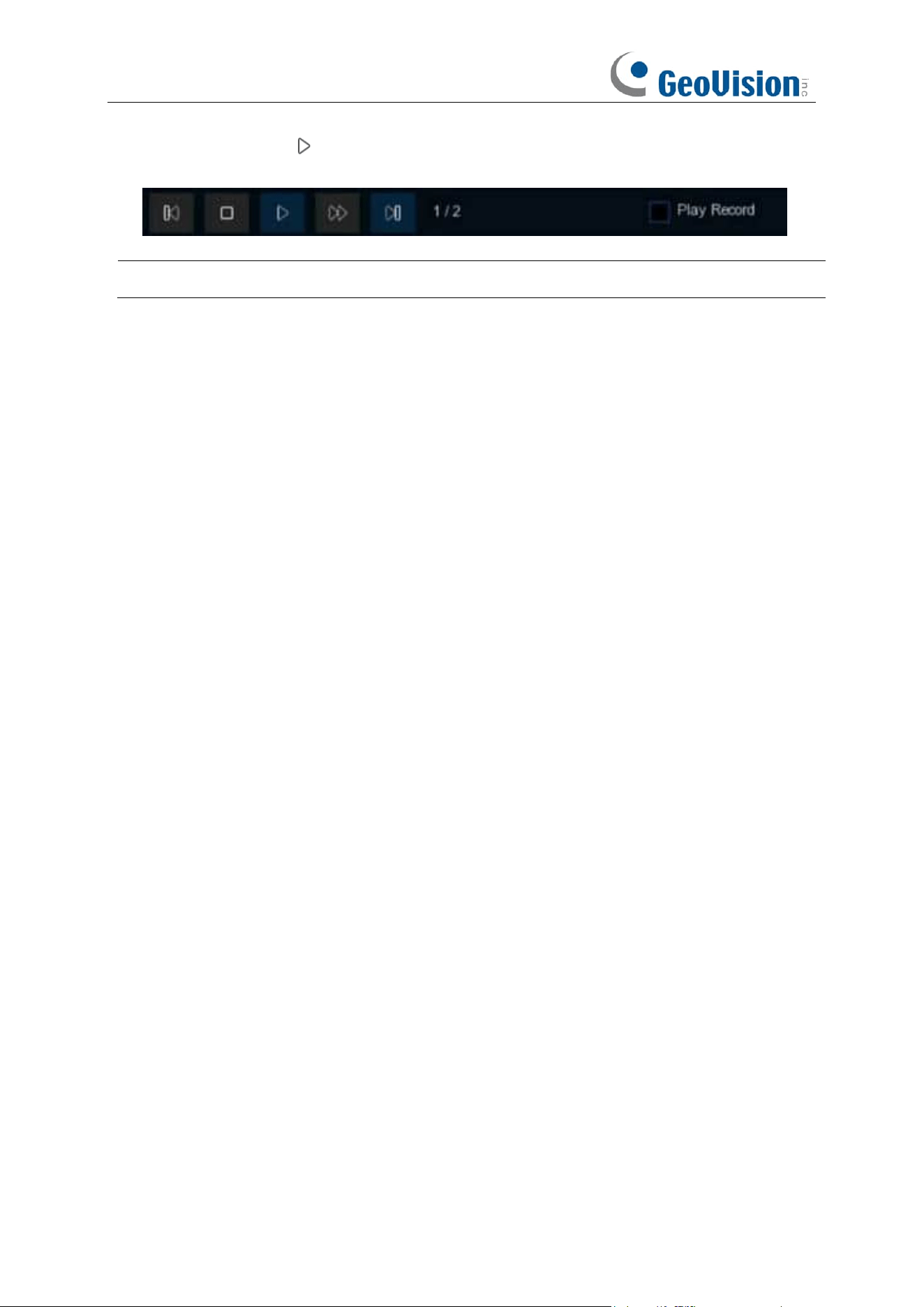
249
5. Click the play button on the play control, the system will automatically demonstrate the
moving track. Check the
Play Record
box, recorded videos will be played meanwhile.
Note:
The tracking function is only applicable to one person at a time.
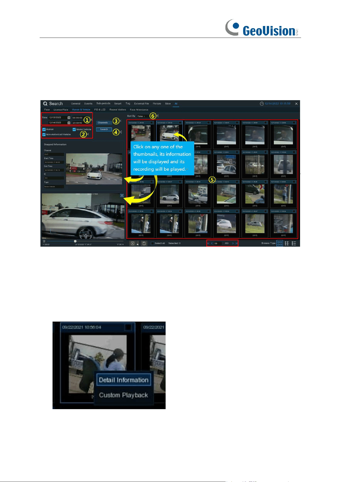
250
7.1.9.2 Human & Vehicle
The system provides a quick search for pedestrians and vehicles.
1. Select the date & time, channel(s).
2. Choose the detection type: Human and/or Vehicle.
3. Click Search, the result will be displayed on the right side of the window.
4. Click one of the images, the system will show its basic information on the left side of the
window, and the video will be played on the left bottom side.
5. Right click your mouse upon one of the images, you will have 2 options:
A. To view the file information.
B. To start playback of the file.
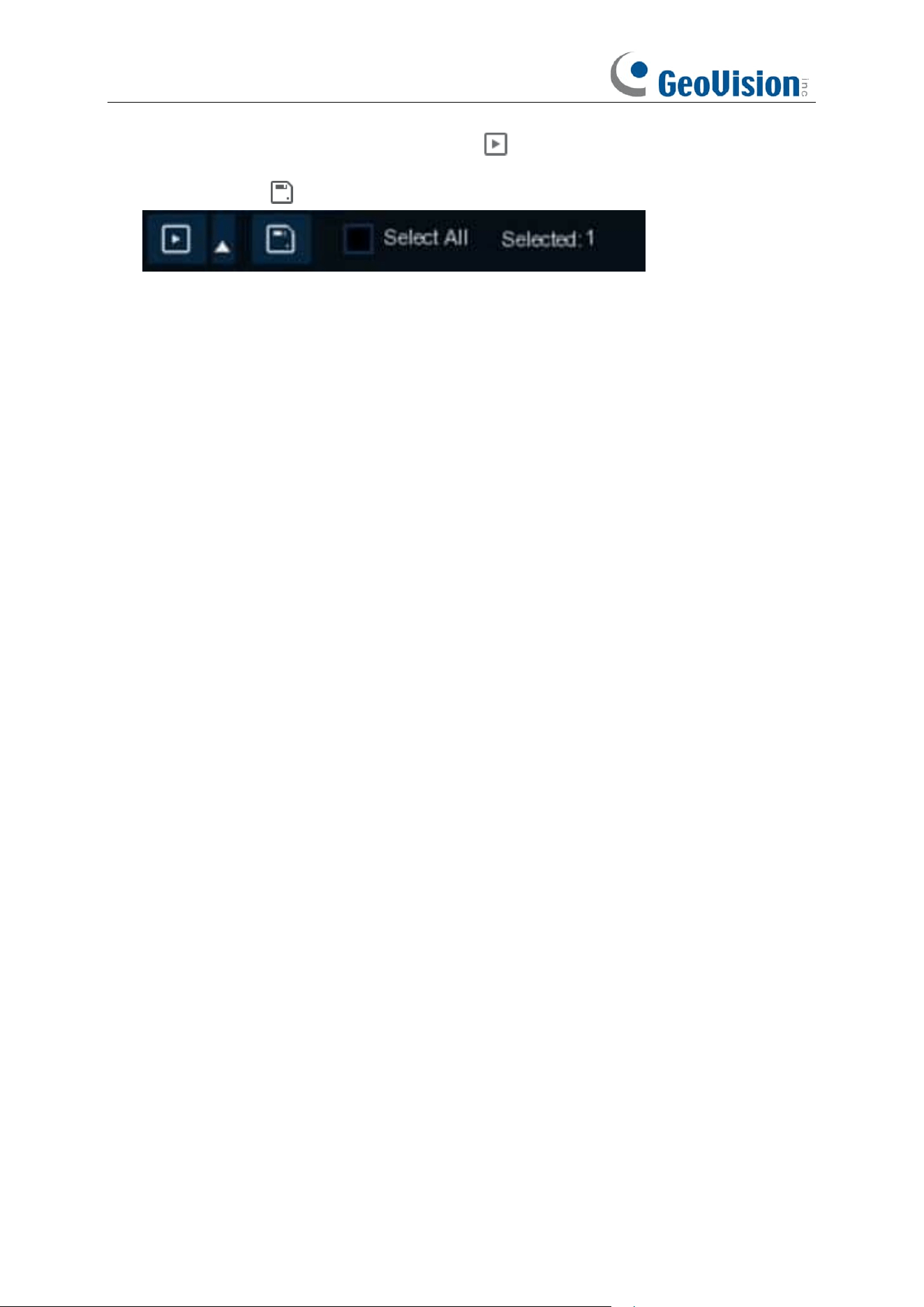
251
6. Choose one or more files, click the play button , the system will turn to the playback
interface to play the selected file(s). Click the
icon to select the time duration you would
like to play. Click to save the selected file(s) to your USB memory.
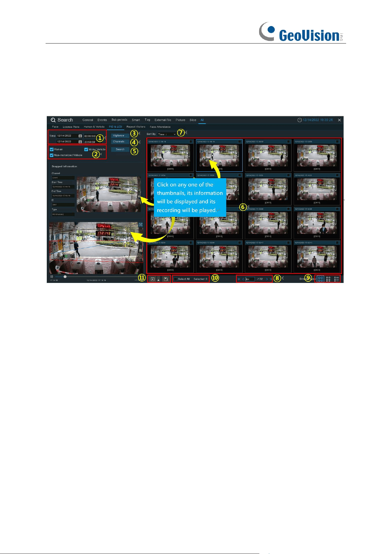
252
7.1.9.3 PID & LCD
The system provides a quick search for PID & LCD.
1. Click the calendar icon to select a date to search on. A red underline on a date indicates human
and/or vehicles were taken on those particular dates. For time, you can use the keypad to enter
a specific start and end time.
2. Select the target type(s) you want to search for.
3. Select PID and/or LCD in Vigilance.
4. The system searches all channels by default. You can click the "
Channels
" button to select
specific channel(s) that you want to search for.
5. Click
Search
button to commence a search.
6. The search result will be displayed on the right side of the screen.
7. You can change to display the images in ascending or descending order by time.
8. Use the arrow buttons to turn page or use the keypad to navigate to a specific page.
9. Click these buttons to change how the events are displayed. The default view is Thumbnail,
but you can change it to List or Detail.
10. Tick the checkbox above each event to select it, or tick the checkbox of "
Select All
" to select
all events in current page.
253
11. Click backup button to copy all selected face images to your USB flash drive. If you want
to save video files also, tick the checkbox of "
Record
", and then select the video format, adjust
the length of time before and after the events.
You can click play button to play the selected events, or click to add time duration
before and after the event and then play. See more on 7.1.9.1.1 Playing Events.
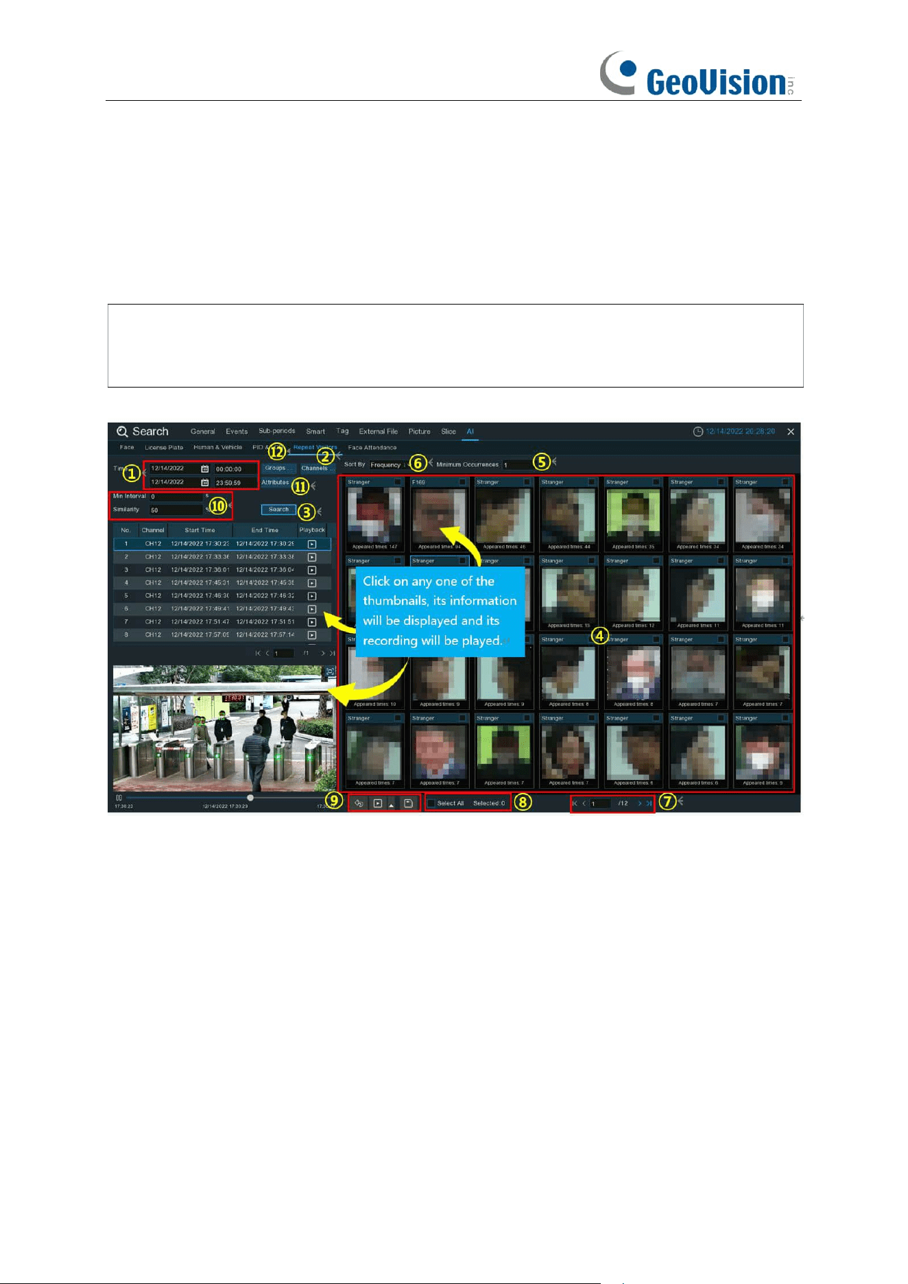
254
7.1.9.4 Repeat Visitors
This is a function to conduct a quick search of the occurrence frequency of persons in a certain
time period.
Note:
The Repeat Visitors function is based Face Detection and/or Face Recognition results.
See 5.4.1.1 FD (Face Detection) and 5.4.2 Face Recognition. Make sure
Face Attribute
is
enabled in
Face Detection
before you can use facial features to find search results.
1. Click the calendar icon to select a date to search on. A red underline on a date indicates
human and/or vehicles were taken on those particular dates. For time, you can use the
keypad to enter a specific start and end time.
2. The system searches all channels by default. You can click the "
Channels
" button to select
specific channel(s) that you want to search for.
3. Click
Search
button to commence a search.
4. The search result will be displayed on the right side of the screen. "
Appeared Times
" under
each thumbnail image indicates how many times the person was captured during your search
period.
5. You can input a number of "
Minimum Occurrences
" to hide the search result whose
appeared time is less than the number of minimum occurrences.
6. You can change to display the images in ascending or descending order by time or frequency.
7. Use the arrow buttons to turn page or use the keypad to navigate to a specific page.
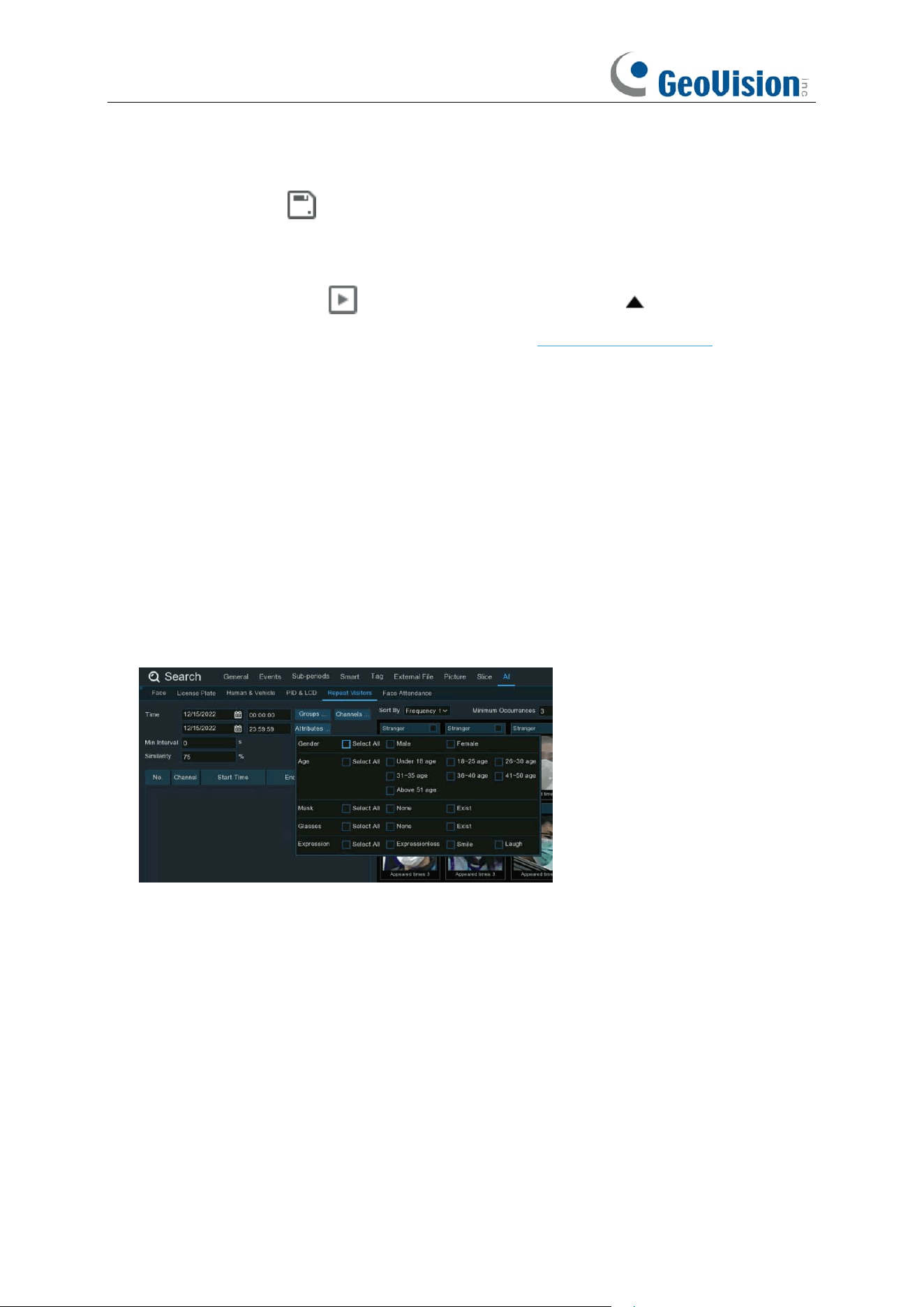
255
8. Tick the checkbox above each event to select it, or tick the checkbox of "
Select
" to select all
events in current page.
9. Click backup button to copy all selected face images to your USB flash drive. If you want
to save video files also, tick the checkbox of "
Record
", and then select the video format, adjust
the length of time before and after the events.
You can click play button to play the selected events, or click to add time duration
before and after the event and then play. See more on 7.1.9.1.1 Playing Events.
10. You can narrow your search by adjusting the "
Min. Interval
" time and the percentage of
"
Similarity
".
Min. Interval
is used to reduce the quantity of searched face images that repeatedly captured
within a short period time. For example, if the Min. Interval is set to 20 seconds, then starting
from the time of the first face image searched on the selected date, all the similar face images
that appear within 20 seconds will only display the first image. The system will display the first
image captured in every 20 seconds.
Similarity is used to set how closely, in percentage terms, the searched faces must match
each other to be considered a recognized same person. A higher percentage of similarity will
result in fewer false recognition results.
11. Furthermore, you can select the face features to execute refined search. Click "
Attributes
"
button, and then select the features you want to search for, and then click
Search
button
again.
12. By default, the system will search and display all captured face images during your searching
time period. If you want to search for the persons whose face profiles had been stored in the
groups, click the Group button and choose the face group(s) accordingly.
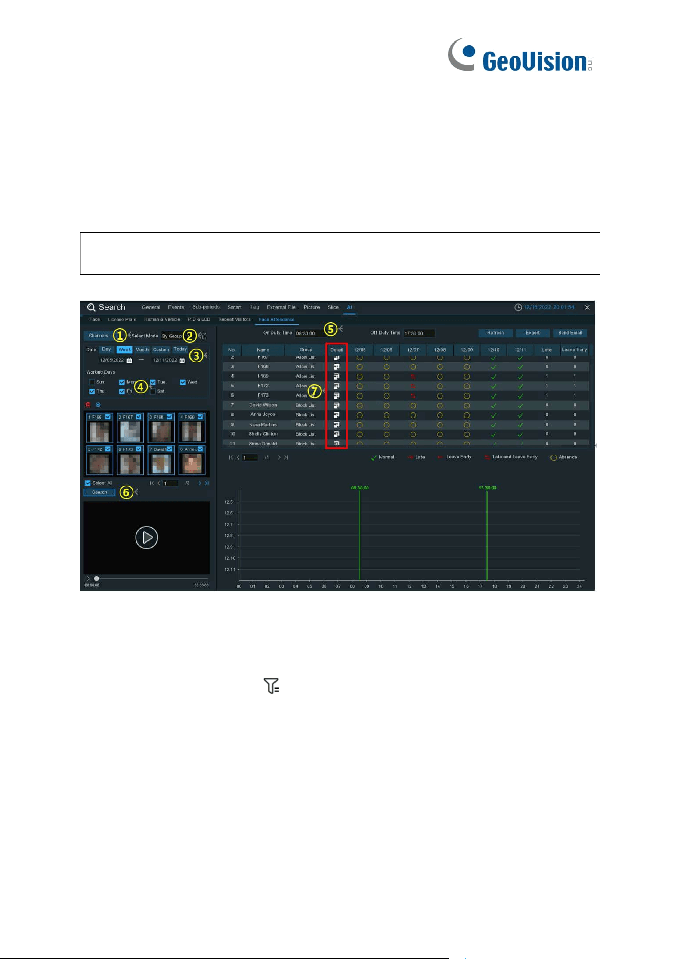
256
7.1.9.5 Face Attendance
Face Attendance is used to assist in attendance checking by faces. It will help analyze the
absenteeism, coming late and leaving early.
Note:
The Face Attendance function is based on Face Detection and/or Face Recognition
results. See 5.4.1.1 FD (Face Detection) and 5.4.2 Face Recognition.
1. Select the channel(s).
2. Select search by Group or by Person. If you choose
By Group
, all the persons in the selected
group(s) will be searched. If you choose
By Person
, only your selected person(s) will be
searched. Click the filter icon to choose group(s) or person(s). Your selected person(s)
will be displayed on the left middle side of the window.
3. Select the search date by an individual day, week, month, current day or customized date.
4. Set the Working Days.
5. Set the On Duty Time and Off Duty Time.
6. Click
Search
button, the result will be displayed on the right side of the window.
You can export the data to your USB flash drive or send by email.
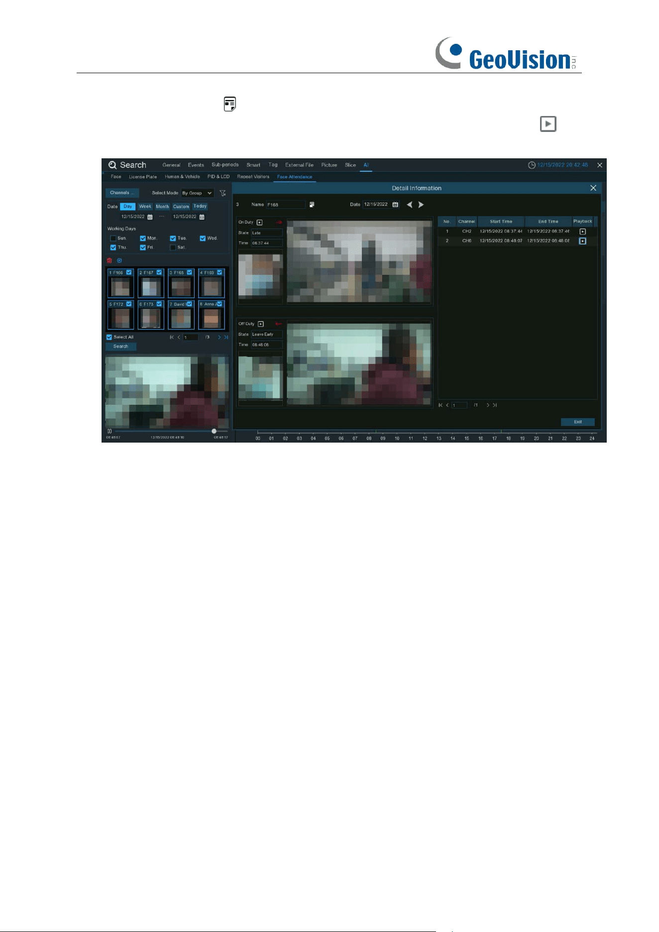
257
7. Click on the detail icon , you will see the captured images and videos of the first
occurrence and the last occurrence of the person in the day. Click on the play button to
have a quick playback.
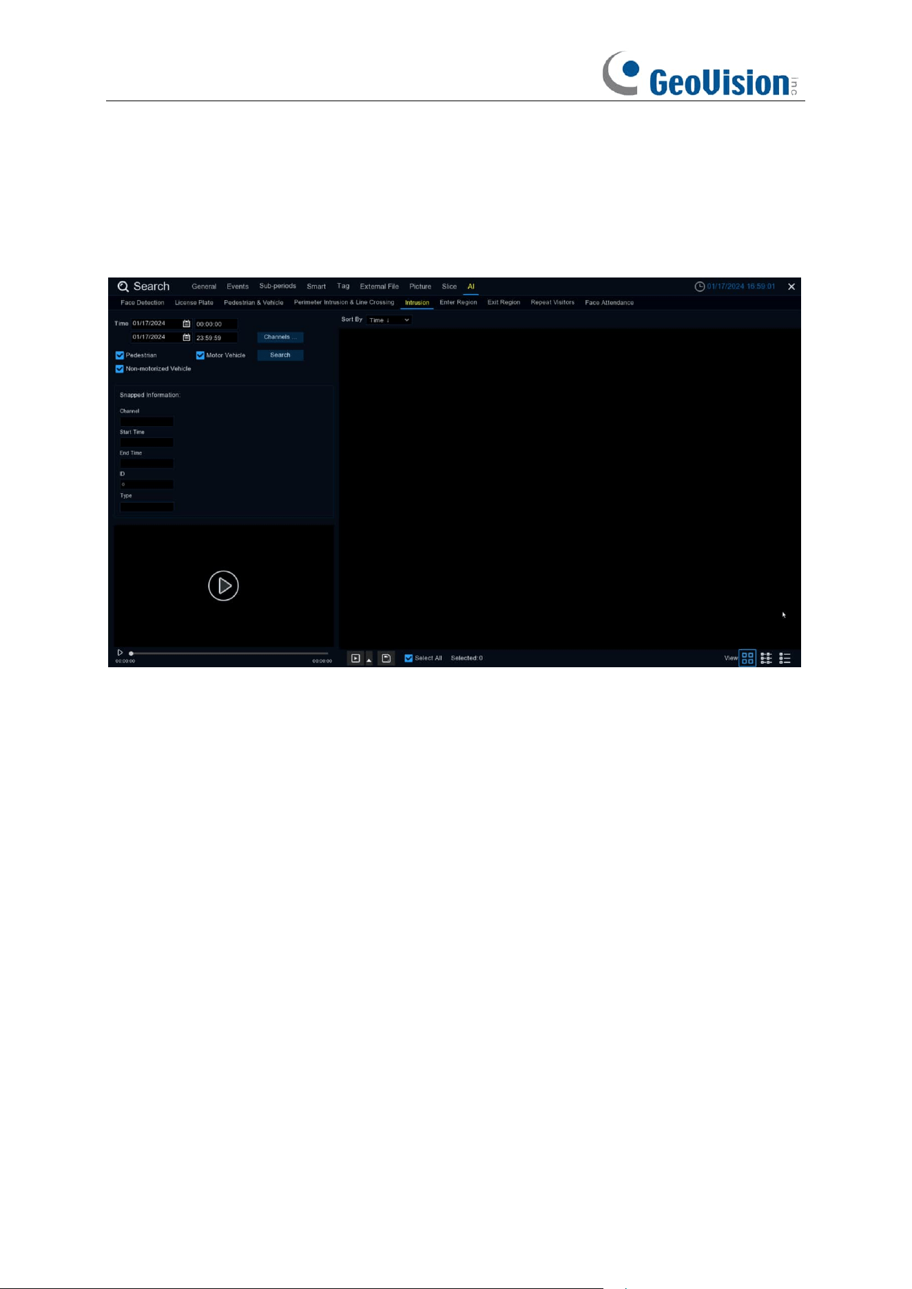
258
7.1.9.6 Intrusion / Region Entrance / Exiting
Select the date, time, channel and detection target type and click Search to search the alarm
events captured during the selected time period.

259
Chapter 8 Remote Access via Web Client
Use the Web Client to remotely access your NVR at any time via a PC. Before you access the
Web Client, you need to ensure that the internet settings of the NVR are configured properly.
8.1 Basic System Environment Requirements
The minimum requirements for hardware and OS required to run Web Client are given as below.
8.2
Web Plugin Download and Installation
To access the Web Client, do the following:
For IE/Chrome/Firefox:
1.
Launch the explorer on your PC and enter the NVR IP address or DDNS domain name (Host
Name) you have set on NVR in the URL box.
2.
For the first time you run the web client, system will require to install the web client plugin. Click
download
to download the plugin and install to your computer.
Item
Minimum
Recommended
CPU
Intel® Core™ i5 CPU
Intel® Core™ i5 CPU or higher
RAM
4G or more
8G or more
Hard Drive
500G or more
1000G or more
Display RAM
2G or more
4G or more
Display Resolution
1280*1024
1920*1080
OS
Windows 7 or above
Mac OS X® 10.9 or above
DirectX
DirectX 11
Direct3D
Acceleration Function
Ethernet Adapter
10/100/1000M Ethernet Adapter
Browser
IE 10 / 11
Safari V12.1 or above
Firefox V52 or above
Google Chrome V57 or above
Edge V79 or above
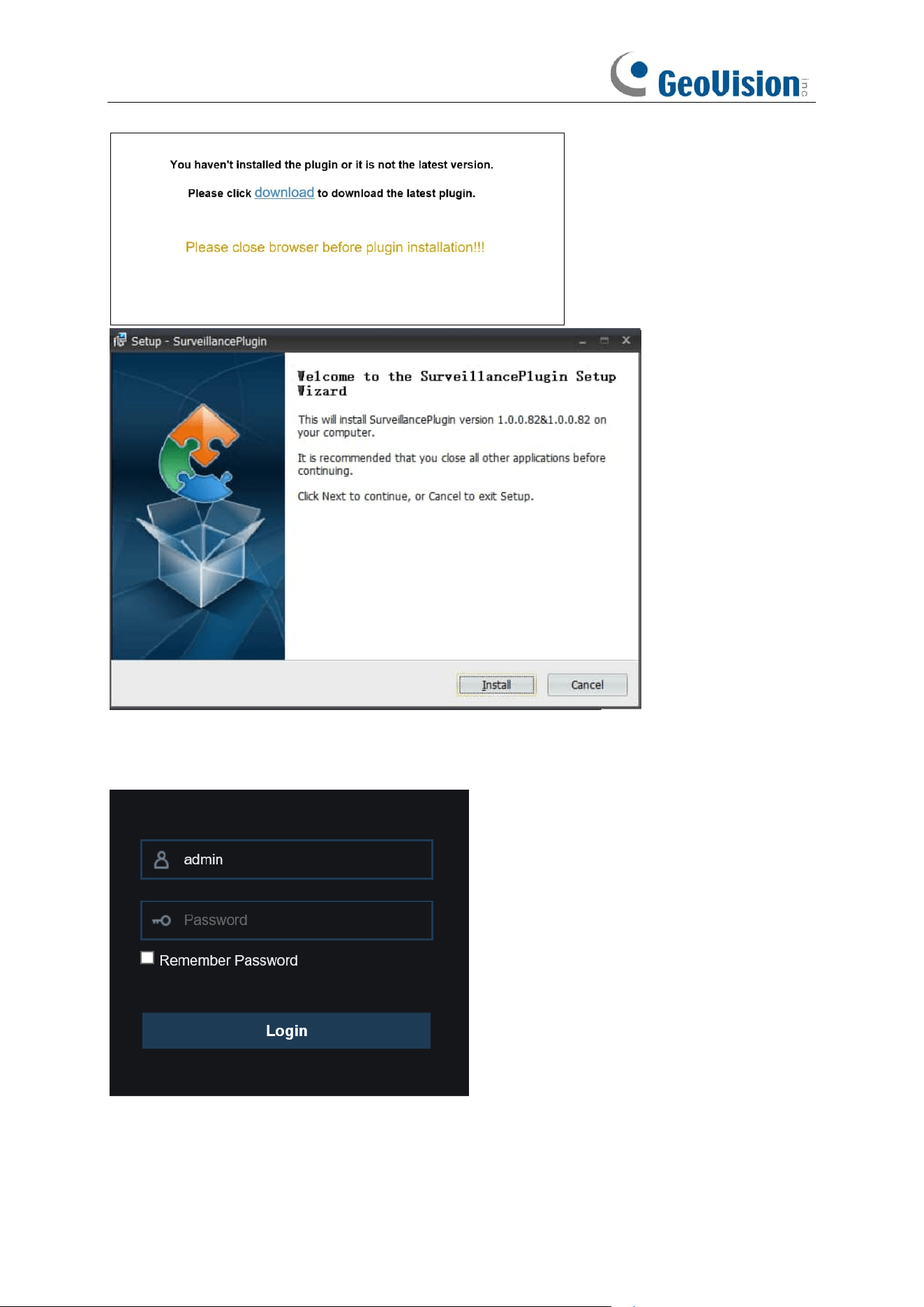
260
3.
After installing the plug-in, close & launch again your browser and repeat step 1 to open the
login page. Input your user name and password to login the web client.
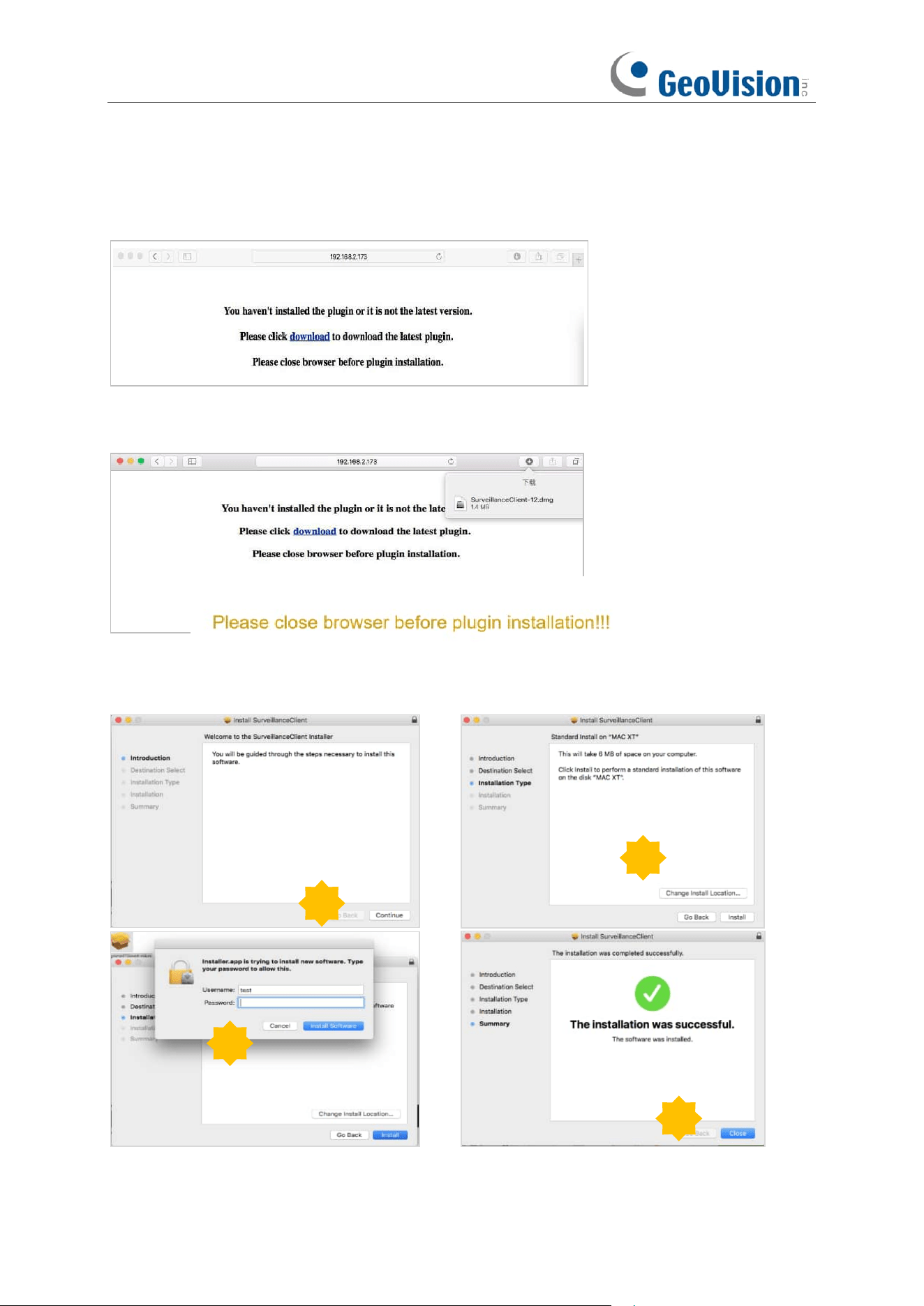
261
For Mac Safari:
1.
Launch the Safari in your Mac, and enter the NVR IP address or DDNS domain name (Host
Name) you have set on NVR in the URL box.
2.
Download the plug-in "SurveillanceClient.dmg", locate the downloaded file and double click it.
3.
Click on "Continue" --> "Install". Enter user name and password for Mac computer,
Click on "Install Software" --> "Close" to finish installation.
4.
Close Safari and open again to repeat step 1 to open the Web Client login page.
1
2
3
4
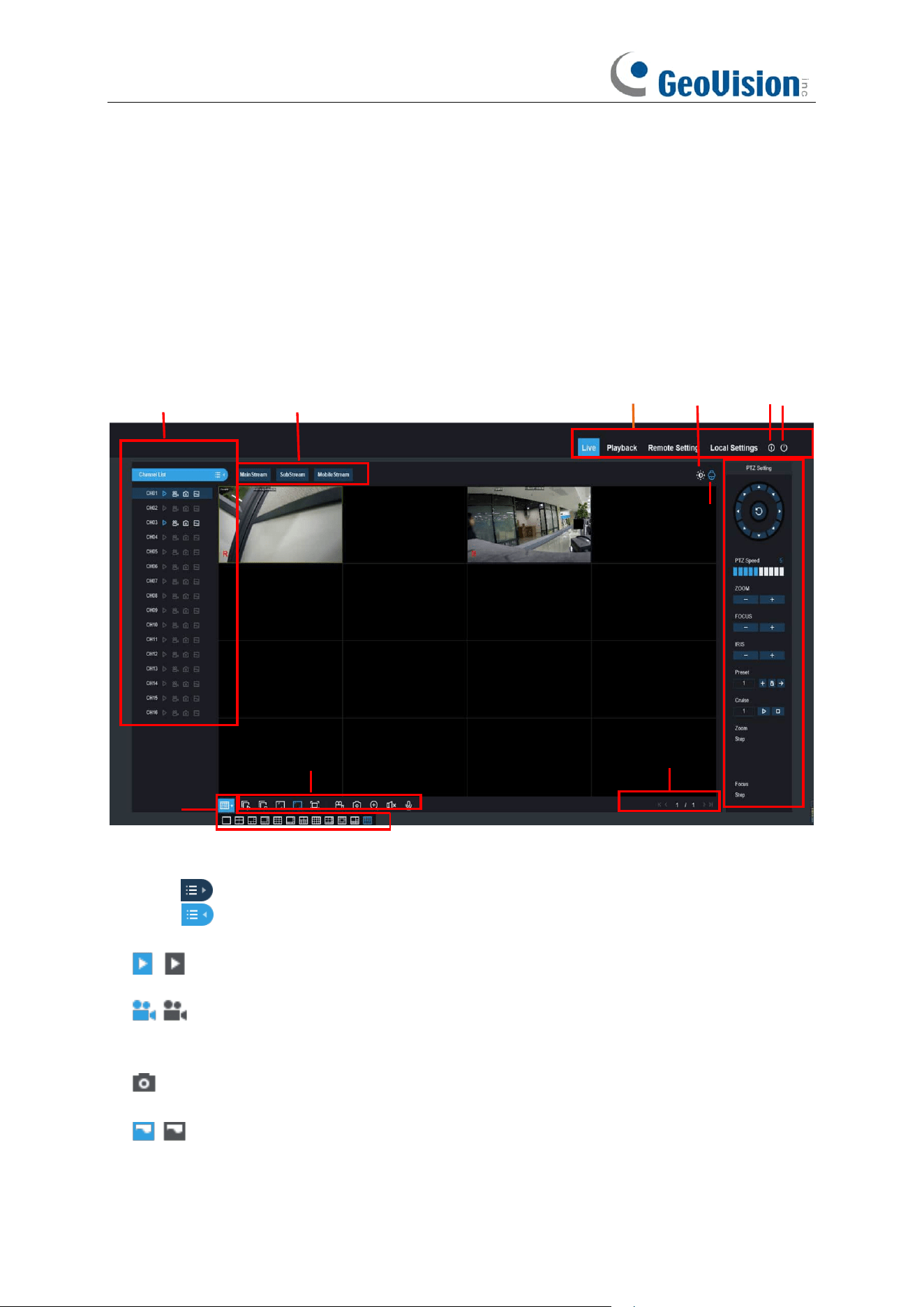
262
8.3 Web Client Manager
The web client supports to fully control the NVR with administrator account. Make sure to protect
your user name & password for preventing illegal login.
8.3.1 Live Interface
This is the first screen that opens after you have logged in to the Web Client. Here you can open or
close live preview, record video to local computer manually, take snapshots of the screens, PTZ
control, color adjustment, etc.
1- Channel List:
Open the channel list for quick camera function
Click button to display the Channel List.
Click button to hide the Channel List.
Turn the Live video stream on/off. The button is in blue color if the live video stream is
on.
Manual Recording buttons. Click to start manually recording live stream video. Click
again to stop recording. Manual recordings are saved to your computer. While in
recording, the button is in blue color.
Manual
snapshot
button. Click to save a snapshot of the current live display to your
computer.
Bitrate button. Set camera to use mainstream, substream or mobile stream video
settings. Mobile stream is available for IP channels only.
1
4
3
5
11
7
6
2
8
9
10
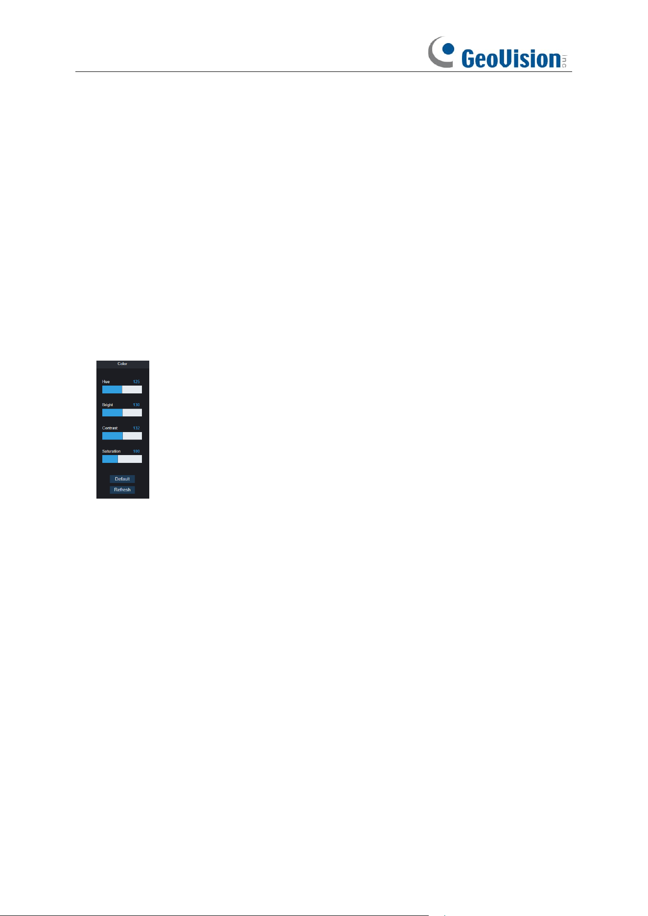
263
2- Live Video Stream Options:
Mainstream:
View all live videos using high-quality mainstream video settings.
Substream:
View all live videos using middle-quality substream video settings.
Mobile Stream:
View all live video using lower-quality mobile stream video settings to
conserve bandwidth. Available for IP channels only.
3- Main Menus:
Live:
View live video from cameras.
Playback:
View recorded video which is saved in NVR’s HDD.
Remote Setting:
Access functions of the NVR setting menus.
Local Settings:
Set download locations for recordings and snapshots taken using Web Client,
and choose file type for video files.
4- Information:
Hover over to see system details.
5- Exit.
6- Color Controls. Click to display or hide the color controls.
7- PTZ Controls:
Click to display or hide the PTZ controls for using PTZ cameras.
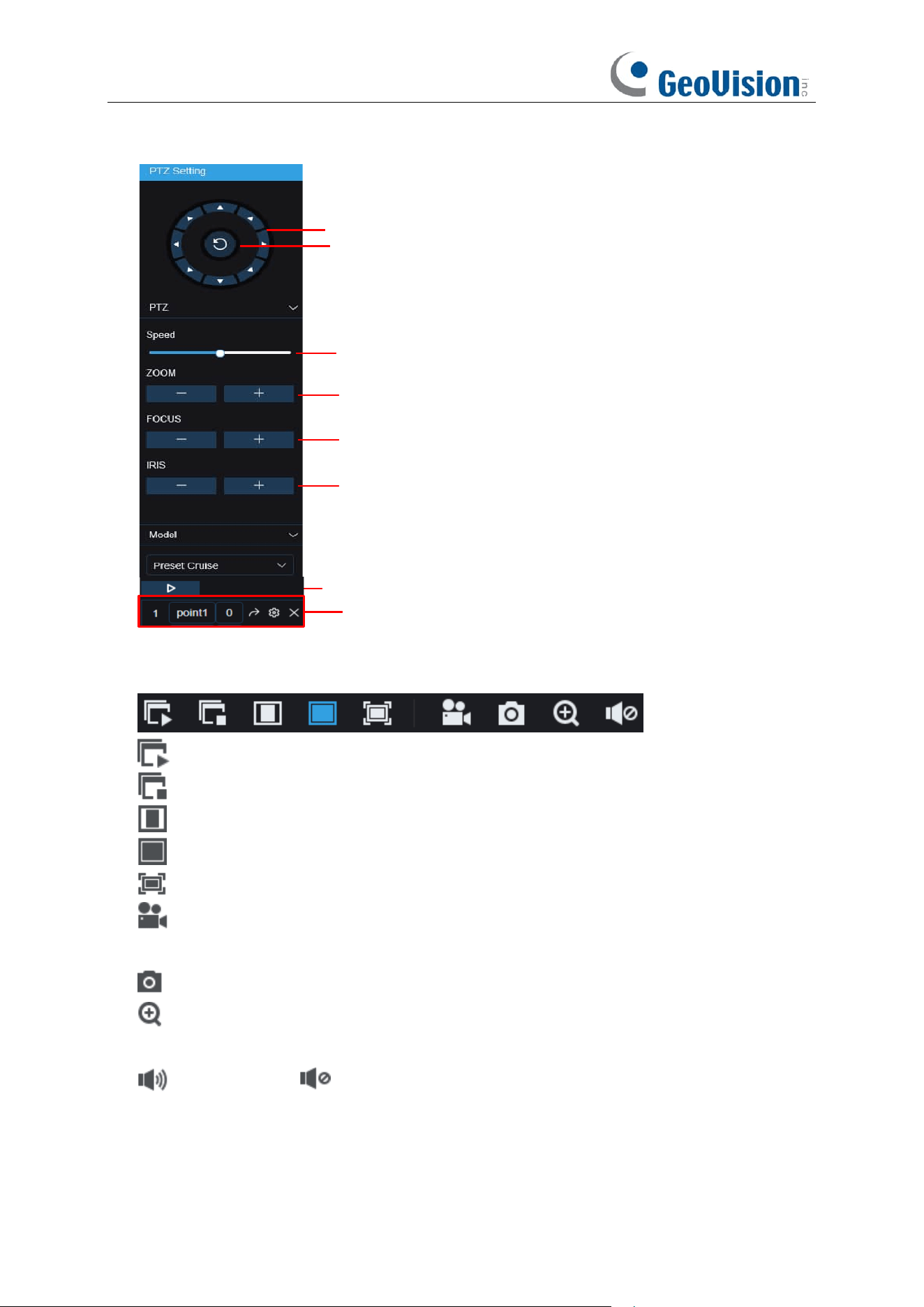
264
8-
PTZ Controls
Directional Arrows: Click to
move the PTZ camera
Automatic line scan
PTZ Speed
ZOOM: Click - / + to zoom in or out.
FOCUS: Click - / + to adjust focus.
IRIS: Click - / + to adjust iris.
Cruise: Start / stop PTZ cruise
Preset Point: Adjust time,
remove, or go to preset point
9- Live View Control Buttons:
Open the images on Live window.
Close all the Live channels
Original Proportions: Shows live video at the original proportions
Stretch: Stretch live video to fit the full area for each channel on screen.
To enlarge the web client to full screen.
Manual Recording: Click to start manually recording for all displayed channels. Click
again to stop recording. Manual recordings are saved to your computer.
Snapshot: Click to save snapshots of all current displayed channels to your computer.
Digital Zoom: Click upon on a live image, then click-and-drag over an area of the live
image to enlarge. Right-click to return to the normal display.
Volume Control. Volume is mute.
10- Navigation:
Shows current page number for the channels shown on screen. Use the arrow
keys to switch between pages.
11- Page View: Click to select how many channels appear on screen at a time.
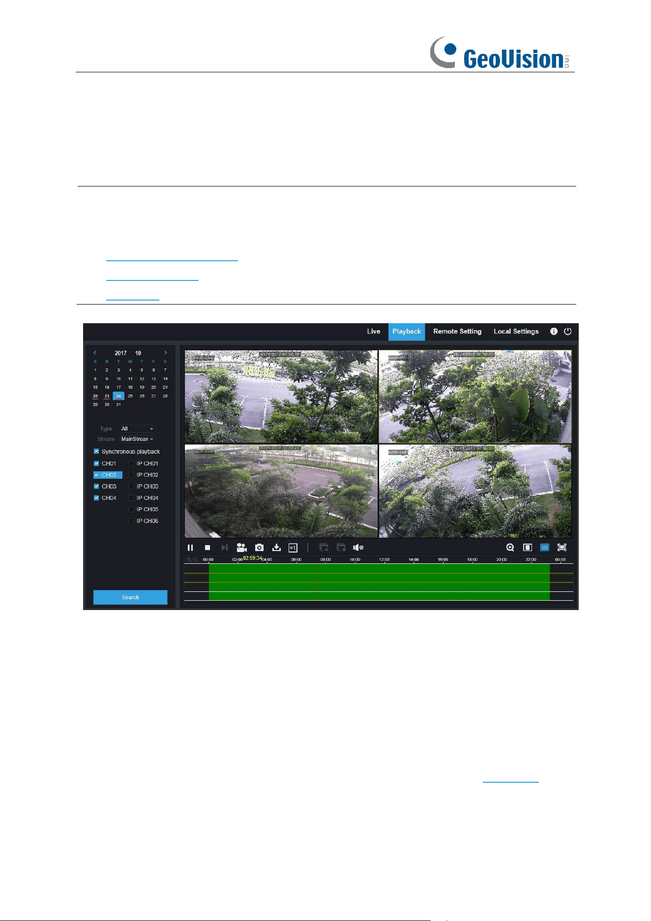
265
8.3.2 Playback
You can search & play recording videos stored in the HDD inside the NVR, and download the
videos to your computer.
Note:
To play the video clips downloaded from the Web Client Manager, install and launch one
of the following players
before
locating the recordings. Wait for 3 ~ 30 seconds before the video
starts to play.
1. GV-R Series Video Player
2. VLC Media Player
3. KM Player
To search recordings:
1. Click Playback in the top-right corner of the window.
2. Select a day on the calendar to search for recordings from. Days with recordings appear
with a red underline.
3. Select the recording type to search for from the dropdown next to Type, or select All to
search for all recordings.
4. To choose the video stream you want to search & play. If you want to play Substream
recordings, make sure you had set the NVR to record with Dualstream at 5.2 Record.
5. Check the channels you would like to search for recordings from. Check Synchronous
playback to play all channels at once.
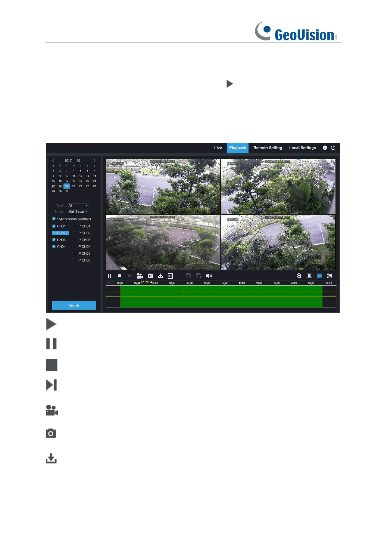
266
6. Click Search.
7. Recordings that fit your search will be displayed in the timeline. Click a section of video
where you would like to begin playback and click the play button.
8.3.2.1 Playback Control Buttons
Play the recordings
Pause
Stop
Go Forward One Frame:
Move frame-by-frame through playback. Only available when the
Synchronous playback
option is not checked.
Click upon one of the channels which is being played and then click record button to record
current video to your computer. Click again to stop recording.
Click upon one of the channels which is being played and then click capture button to take a
snapshot and save to your computer.
Opens the Download menu, which allows you to download several video recordings at once.
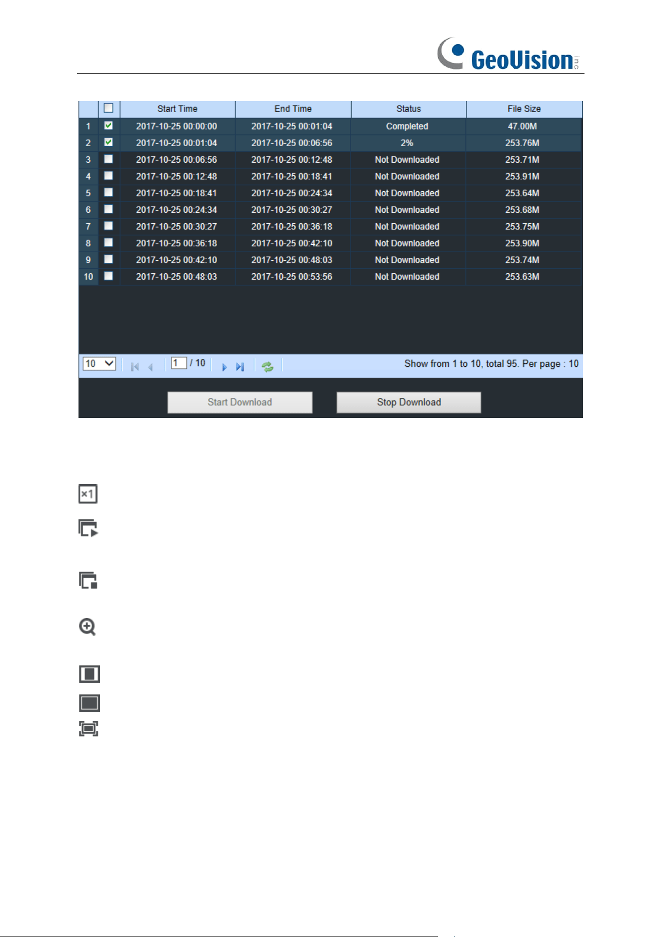
267
Choose the files you want to download, press
Start Download
button to begin, you will see the
download status. Press
Stop Download
button to stop.
Playback Speed.
Click to choose the playing speed.
Play All Channels:
Click to play all channels you have chosen to searched. Only available
when the
Synchronous playback
option is not checked.
Stop All Channels:
Click to stop playing all channels. Only available when the
Synchronous playback
option is not checked.
Digital Zoom: Click upon on a playing video, then click-and-drag over an area of the video to
enlarge. Right-click to return to the normal display.
Original Proportions: Shows the playing video at the original proportions
Stretch: Stretch the playing video to fit the full area for each channel on screen.
To enlarge the web client to full screen.
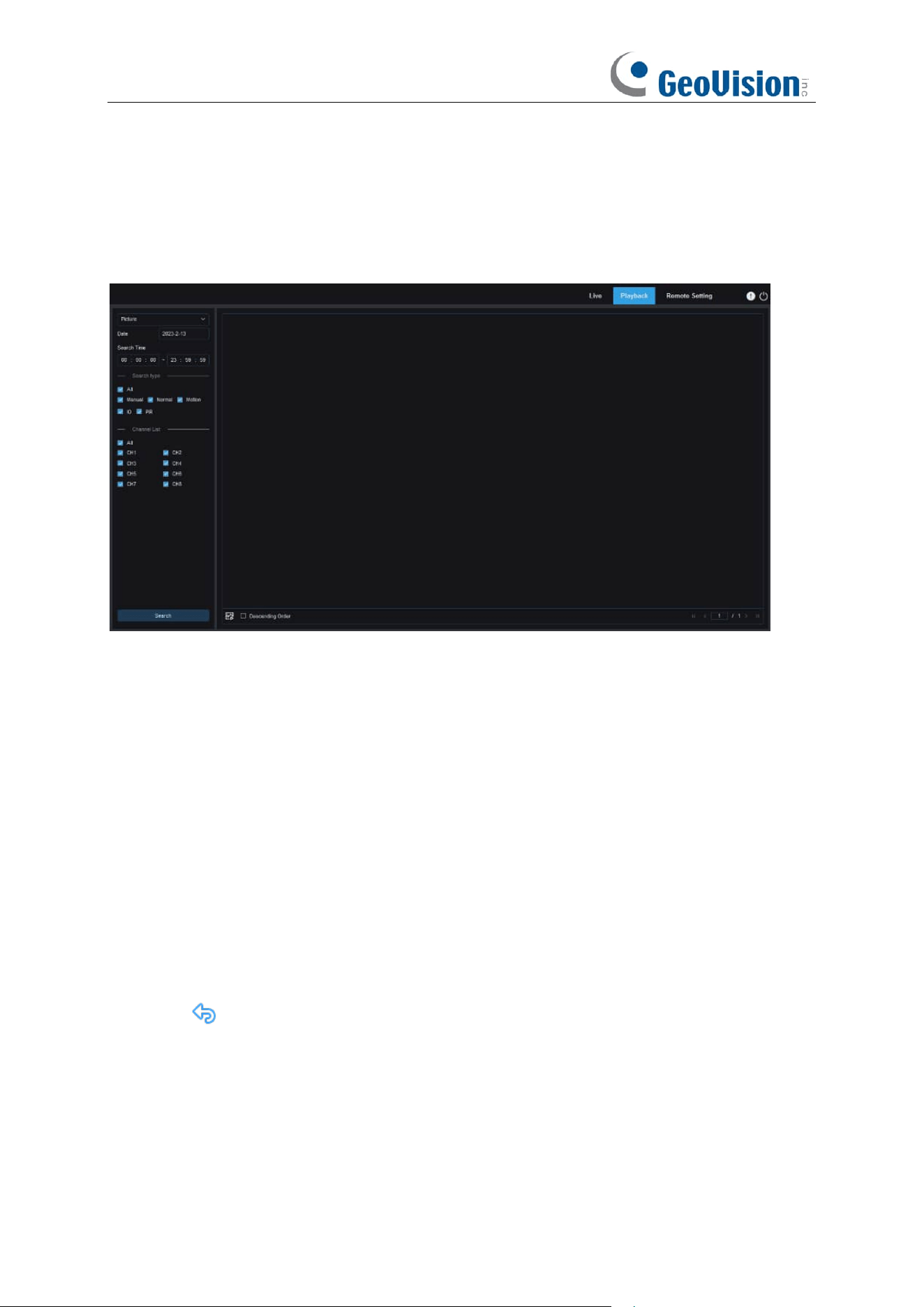
268
8.3.2.2 Image Playback
After the capture function is enabled for the device, you can search the captured images on this
page. A maximum of 5000 images can be searched at a time, and the time interval can be
modified as needed.
Searching images:
1. Click Playback in the top right corner of the page.
2. Select Picture from the drop-down list in the top left corner of the page.
3. Select the day to be searched on the calendar. The dates with snapshots are underlined in
red.
4. Select the image types to be searched from the Search Type menu, or select All to search all
image types.
5. Select the channels of which videos are to be searched.
6. Click Search.
7. The images meeting the search conditions are displayed in the right pane. If you double-click
an image, the videos with the time periods before and after the image will be played back.
Click to return to the previous page.
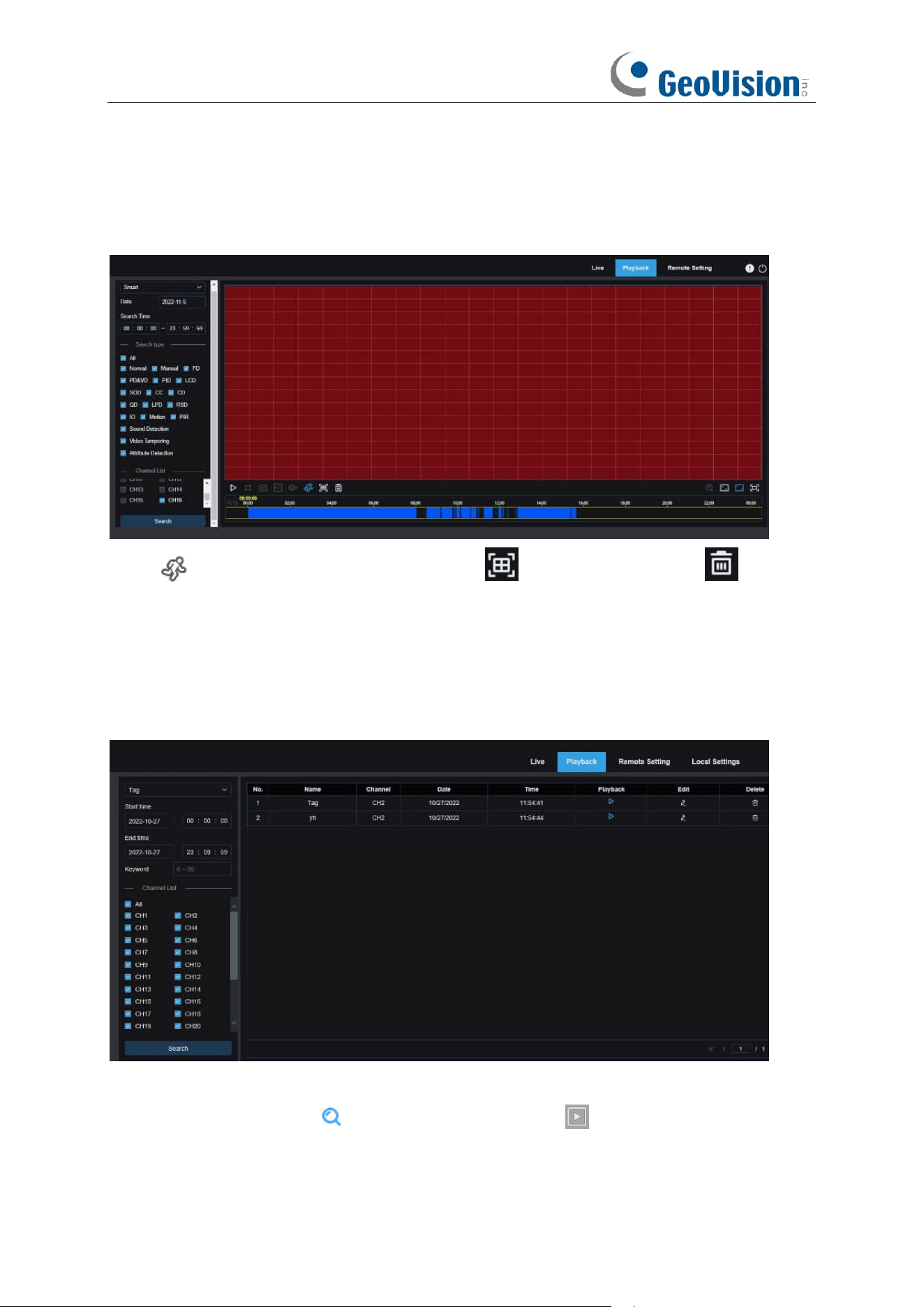
269
8.3.2.3 Smart Playback
After the motion detection function is enabled for the device, if there are motion detection alarms
triggered, you can search the smart playback videos.
Click to display the smart setting area. Click to select all areas. Click to clear
all selected areas.
8.3.2.4 Playback by Tag
On this page you can search all added tags, and edit, play back, or delete them as needed. Select
time and channels, and click to complete the search. Click to jump to the position marked
by the tag to play back the video.
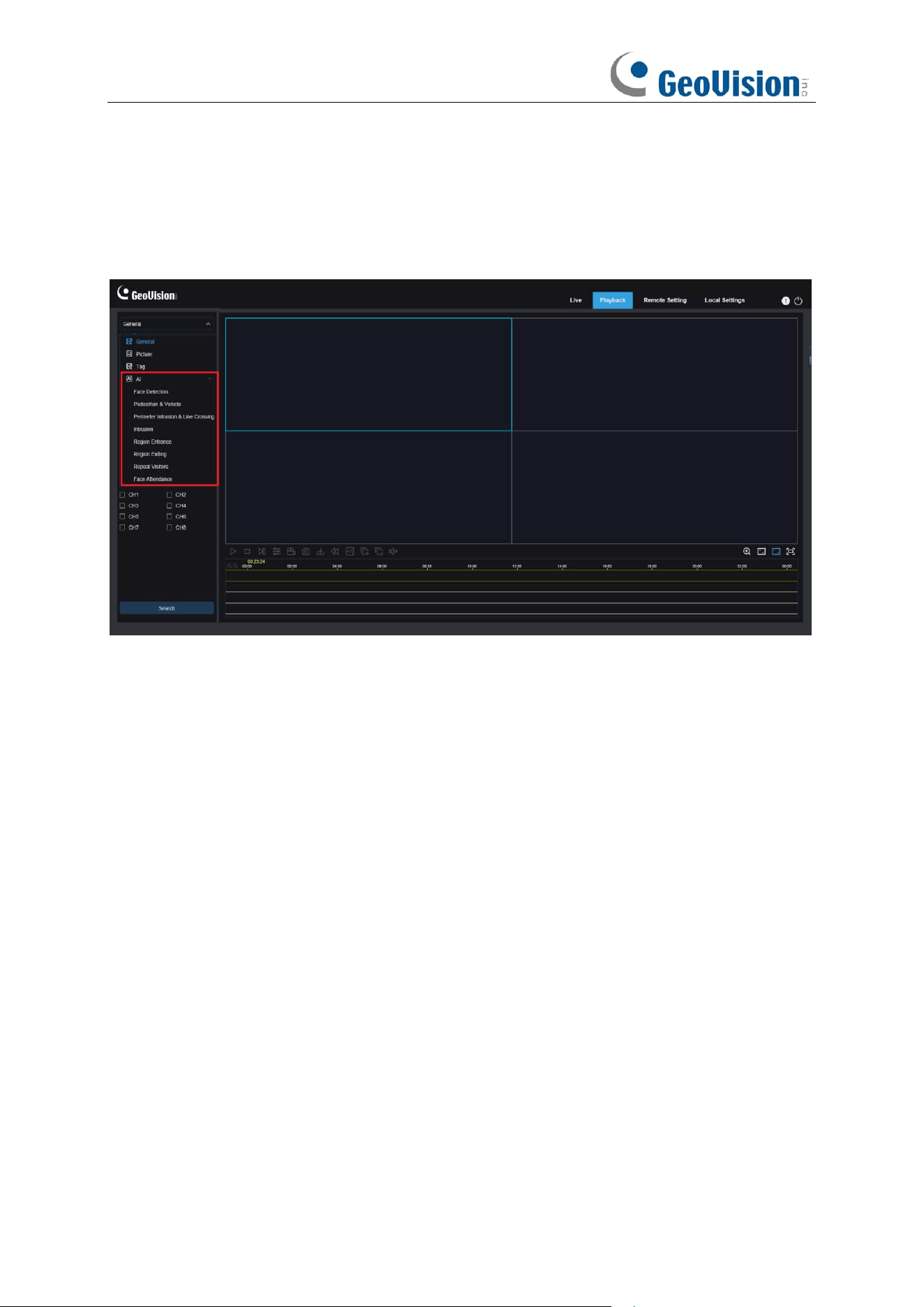
270
8.3.2.5 AI Playback
After the AI alarm function is enabled for the device, you can search AI alarm events on this page,
including Face Detection, Pedestrian and Vehicle Detection, PID&LCD, Repeat Visitors, and Face
Attendance, Intrusion, Region Entrance / Exiting events.
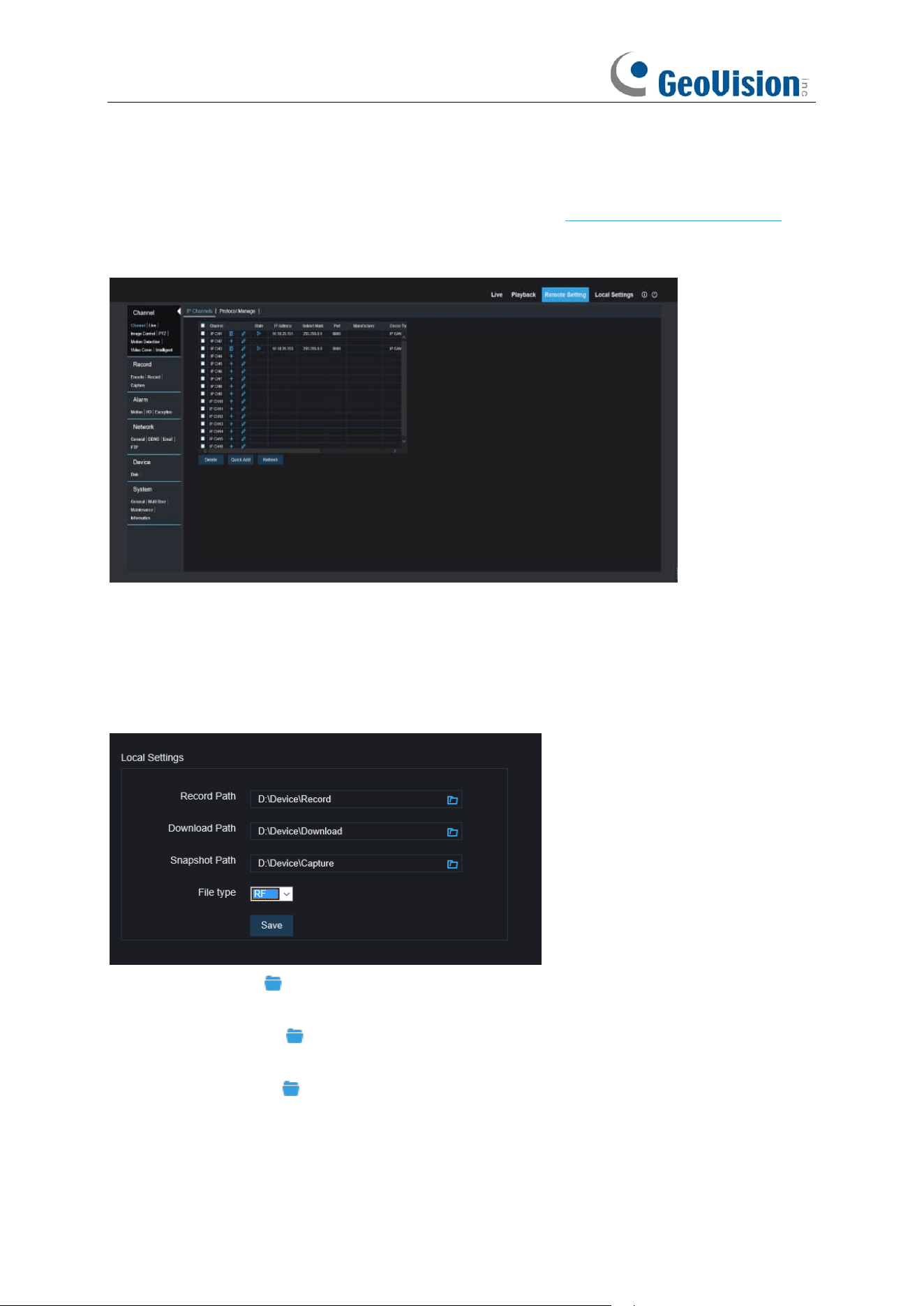
271
8.3.3 Remote Setting
Here you can remotely configure the settings of the NVR. See “Chapter 5 NVR System Setup” for
details on the NVR settings.
8.3.4 Local Setting
Set download locations for recordings and snapshots taken using Web Client, and choose file type
for video files.
Record Path:
Click to browse for and select the folder where you would like the manual
video recordings to be saved on your computer.
Download Path:
Click to browse for and select the folder where you would like to save the
download video recordings to your computer.
Snapshot Path:
Click to browse for and select the folder where you would like the manual
capture snapshots to be saved on your computer.
File Type:
Choose your preferred file type for manual recordings.
Save:
Click to save the modifications.


273
B. Troubleshooting
1. Q: What can I do if the system does not detect the HDD?
A: Check if the power supply system is properly connected and data cord and power cables
are securely connected, and if something wrong with the HDD interface. Or you may check if
your HDD is supported by referring to the specifications or descriptions.
2. Q: I have changed the password but forget the new password, how can I access the
system?
A: If you forget system password, consult with our technical personnel. We strongly suggest
user to set password easy to be remembered and relatively safe. If you have safety
requirement, do not set very simply password, such as 000000.
3. Q: We see abnormal video signal or even no video signal by connecting the NVR and
camera together. Power supply for both devices is OK. What is wrong?
A: Check network cable at NVR side to see if the cable is firmly connected and if it is worn out
and needs to be replaced, or to check if NTSC or PAL is selected consistently.
4. Q: How to prevent NVR from being influenced by heat?
A: The NVR needs to dissipate heat while it is running. Place the NVR in a place with good air
circulation and away from heat sources to ensure stability and life of the NVR.
5. Q: The remote controller of NVR doesn’t work while the monitor screen is OK and
panel keys are functional. Why?
A: Operate again by aiming the remote controller at the IR receiver on front panel. If it still
doesn’t work, check if the batteries in the remote controller are dying. If not, check if the
remote controller is broken.
6.
Q: I want to take out HDD from my PC and install it in NVR. Can it work?
A: All HDDs supported by the system can be used. But remember, once NVR runs, the data
on your HDD will be lost.
7.
Q: Can I play back while recording?
A: Yes. The system supports the function of playing while recording.
8.
Q: Can I clear some records on HDD of NVR?
A: In consideration of the file security, you may not clear part of records. If you want to remove
all the records, you can format HDD.
9.
Q: Why can’t I log in NVR client?
A: Check if the network connection settings are correct and RJ-45 port is with good contact.
And check if your account and password are correctly input.
10.
Q: Why can’t I find any records during playback?
A: Check if the data line connection for HDD is OK and system time is properly adjusted. Try a
few times and restart. If it still doesn’t work, check if the HDD is broken.

274
Q: Why NVR cannot control PTZ?
A: Check if:
a) PTZ in the front side is malfunctioned.
b) Setting, connection and installation of PTZ decoder are not correct.
c) PTZ setting of NVR is not correct.
d) Protocol of PTZ decoder does not match that of NVR.
e) Address of PTZ decoder does not match that of NVR.
f) If many decoders are connected, the farthest side of AB line of PTZ decoder should be
added 120Ω resistance to realize reflection suppression and impedance matching.
Otherwise, PTZ control will be unstable.
11.
Q: Why doesn’t dynamic detection work?
A: Check if the motion detection time and motion detection regional setting are correct and if
the sensitivity is set too low.
12.
Q: Why doesn’t alarm work?
A: Check if the alarm setting, alarm connection and alarm input signals are correct.
13.
Q: Why does buzzer keep alarming?
A: Check the alarm setting, check if motion detection function is enabled and object motion is
detected all the time and if I/O alarm is set as Always Off. Besides, refer to corresponding HDD
alarm setting.
14.
Q: Why can’t I stop recording by pressing “STOP” button or click “Stop Recording” in
context menu?
A: Pressing Stop or Stop Recording can only stop manual record. If you want to stop
Scheduled recording in certain time quantum, change the setting to No Record. To stop
Startup recording, change record mode to scheduled recording or manual recording. Then
you may stop recording by the prescribed methods. And another way of stopping recording
is to set channel as off status in record setting.

275
C. Usage Maintenance
1. To shut down NVR, firstly shut down the system and then turn off the power. Do not turn off
the power directly or HDD data will be lost or damaged.
2. Keep NVR away from heat sources or places.
3. Clean the internal dust regularly. Make sure the good ventilation of NVR so as to ensure the
good heat dissipation.
4. Do not hot plugging audio and video cables, or cables connected to ports like RS-232 or
RS-485. Otherwise, the ports will be damaged.
5. Check the HDD cable and data cable regularly to see if they are ageing.
6. Prevent the audio and video signals of NVR from being intervened by other electronic devices,
and prevent the HDD from being damaged by static electricity and induced voltage. If the
network cable is frequently plugged, it is suggested to replace connecting line regularly, or the
input signal may be unstable.
7. This is a class A product. It maybe bring wireless interference in life. Under this situation, it
need user to make measures.