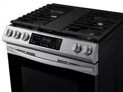

Dual Fuel Range
Installation manual
NSY6
**
8
*
5
***
DG68-01650A-02_IM_NSY6DG8550SRAA_EN+MES+CFR.indb 1DG68-01650A-02_IM_NSY6DG8550SRAA_EN+MES+CFR.indb 1 2024-12-03 오후 4:13:242024-12-03 오후 4:13:24
2 English
Contents
Contents
Before you begin 3
Important safety information 4
Read all instructions before using this appliance 4
Symbols used in this manual 4
California Proposition 65 Warning 4
Commonwealth of Massachusetts 4
General safety 4
Fire safety 5
Gas safety 5
Electrical and grounding safety 6
Installation safety 6
Location safety 7
Cooktop safety 7
Oven safety 8
Storage drawer safety 9
Self-cleaning oven safety 9
Dual fuel range components 10
What’s in the box 10
Installation requirements 11
Location requirements 11
To avoid breakage 14
Gas requirements 15
Special gas requirements (gas models sold in Massachusetts) 15
Electrical requirements 16
WARNING
If the information in this manual is not followed exactly, a re or
explosion may result causing property damage, personal injury or death.
• DO NOT store or use gasoline or other ammable vapors and liquids
in the vicinity of this or any other appliance.
• WHAT TO DO IF YOU SMELL GAS:
- DO NOT try to light any appliance.
- DO NOT touch any electrical switch.
- DO NOT use any phone in your building.
- Immediately call your gas supplier from a neighbor’s phone.
Follow the gas supplier’s instructions.
- If you cannot reach your gas supplier, call the re department.
• Installation and service must be performed by a qualied installer,
service agency, or the gas supplier.
Anti-tip device
WARNING
ALL RANGES CAN TIP, RESULTING IN PERSONAL INJURY.
TIPPING RANGES CAN CAUSE BURNS FROM SPILLS, PERSONAL
INJURY, AND/OR DEATH.
INSTALL AND CHECK THE ANTI-TIP BRACKET FOLLOWING THE
INSTRUCTIONS AND TEMPLATE SUPPLIED WITH THE BRACKET.
• To prevent accidental tipping of the range, attach an approved
anti-tip device to the oor. (See Installing the Anti-Tip Device in the
Installation Instructions.) Check for proper installation by carefully
tipping the range forward. The anti-tip device should engage and
prevent the range from tipping over.
• If the range is pulled out away from the wall for any reason, make
sure the anti-tip device is reengaged after the range has been pushed
back into place.
• Follow the installation instructions found in the Installation Manual.
Failure to follow these instructions can result in death, serious
personal injury, and / or property damage.
• To prevent accidental tipping of the range, DO NOT step, sit, or lean
on the door or drawer.
• Be sure your appliance is properly installed and grounded by a
qualied technician.
DG68-01650A-02_IM_NSY6DG8550SRAA_EN+MES+CFR.indb 2DG68-01650A-02_IM_NSY6DG8550SRAA_EN+MES+CFR.indb 2 2024-12-03 오후 4:13:242024-12-03 오후 4:13:24

English 3
Before you begin
Installation instructions 17
Installing your dual fuel range 17
Step 1. Unpack the range 17
Step 2. Meeting electrical connection requirements 17
Step 3. Accessing the power cord connection 18
Step 4. Installing the power cord 19
Step 5. Installing the conduit 20
Step 6. Replacing the access cover 22
Step 7. Connect the range to gas supply 22
Step 8. Convert to LP gas (optional) 23
Step 9. Install the anti-tip device 24
Step 10. Plug in and place 24
Step 11. Level the range 25
Step 12. Assemble the surface burners 25
Step 13. Check the ignition of surface burners 26
Step 14. Final installation checklist 27
ABOUT THIS MANUAL
READ THESE INSTRUCTIONS COMPLETELY AND CAREFULLY.
IMPORTANT NOTE TO THE INSTALLER
• Read all instructions contained in these installation instructions before
installing the range.
• Remove all packing materials from the oven compartments before connecting
the electric and gas supply to the range.
• Observe all governing codes and ordinances.
• Be sure to leave these instructions with the consumer.
• Installation of this appliance requires basic mechanical skills.
• Proper installation is the responsibility of the installer.
• Product failure due to improper installation is not covered under the Warranty.
IMPORTANT NOTE TO THE CONSUMER
Keep these instructions with your user manual for future reference.
• As when using any appliance generating heat, there are certain safety
precautions you should follow.
• Be sure your range is installed and grounded properly by a qualied installer
or service technician.
• Make sure the wall coverings around the range can withstand the heat
generated by the range.
• Cabinet storage space above the surface burners should be a minimum of
30 in (76.2 cm).
IMPORTANT NOTE TO THE SERVICER
The electrical diagram is in an envelope attached to the back of the range.
Before you begin
DG68-01650A-02_IM_NSY6DG8550SRAA_EN+MES+CFR.indb 3DG68-01650A-02_IM_NSY6DG8550SRAA_EN+MES+CFR.indb 3 2024-12-03 오후 4:13:242024-12-03 오후 4:13:24
4 English
Important safety information
Important safety informationImportant safety information
READ ALL INSTRUCTIONS BEFORE USING THIS
APPLIANCE
• All electrical and gas equipment with moving parts can be dangerous. Please
read the important safety instructions for this appliance in this manual.
The instructions must be followed to minimize the risk of injury, death, or
property damage.
• Save this manual. Please Do Not Discard.
SYMBOLS USED IN THIS MANUAL
WARNING
Hazards or unsafe practices that may result in severe personal injury or death.
CAUTION
Hazards or unsafe practices that may result in electric shock, personal injury, or
property damage.
NOTE
Useful tips and instructions.
These warning icons and symbols are here to prevent injury to you and others.
Please follow them explicitly. After reading this section, keep it in a safe place for
future reference.
CALIFORNIA PROPOSITION 65 WARNING
WARNING
Cancer and Reproductive Harm - www.P65Warnings.ca.gov
COMMONWEALTH OF MASSACHUSETTS
This product must be installed by a licensed plumber or gas tter qualied or
licensed by the State of Massachusetts. When using ball-type gas shut-off valves,
you must use the T-handle type. Multiple exible gas lines must not be connected
in series.
GENERAL SAFETY
WARNING
To reduce the risk of re, electric shock, personal injuries, and/or death, obey the
following precautions.
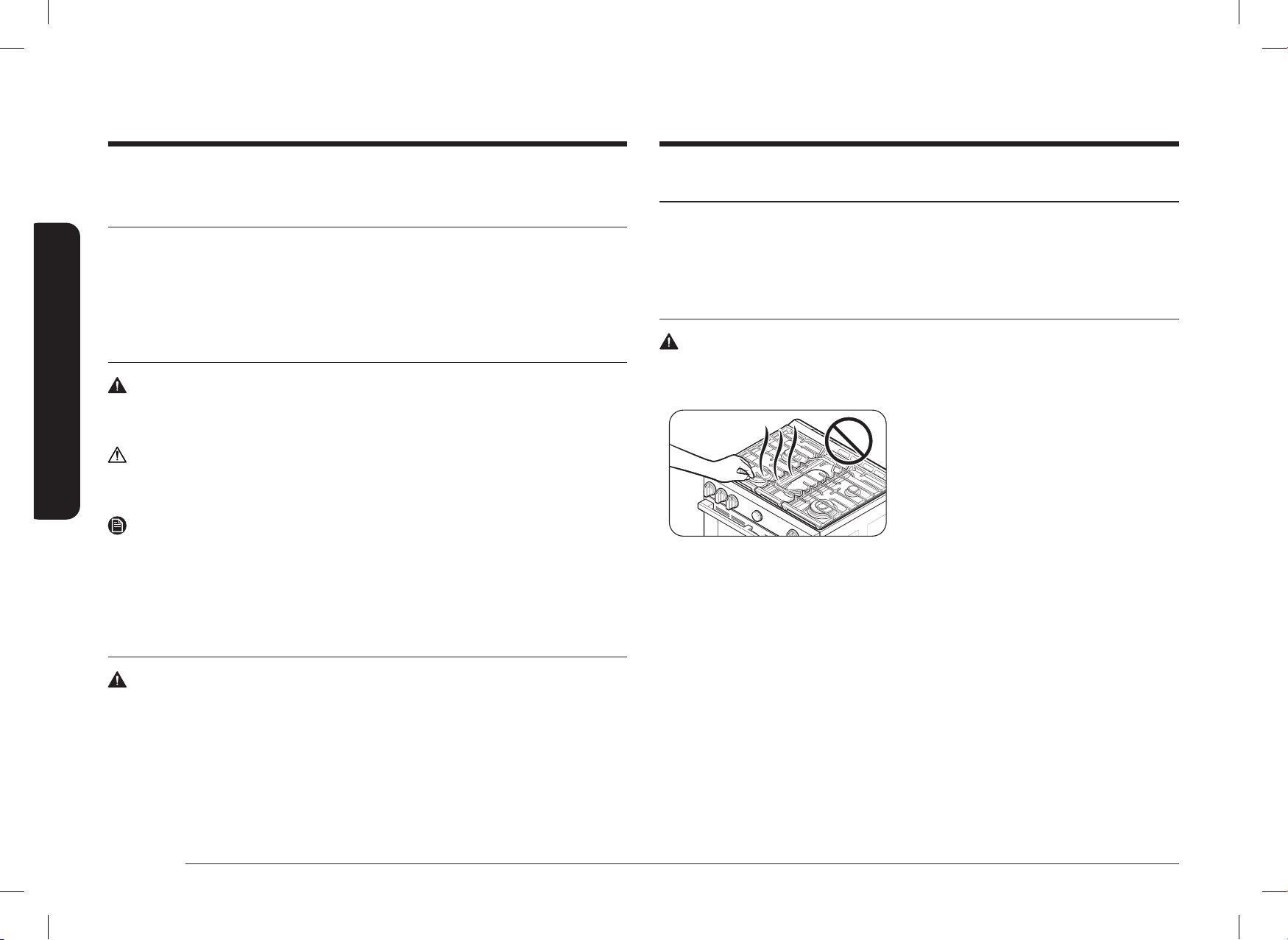
• Do not touch any part of the range,
including but not limited to, oven
burners, surface burners, or interior
surfaces during or immediately after
cooking.
• Know the location of the gas shut-off
valve and how to shut it off.
• Make sure the anti-tip device is properly installed on the range.
See the installation instructions for more information.
• Do not let children near, in, or on the range. Do not let children play with the
range or any part(s) of the range. Do not leave children unattended in an area
where the range is in use. For children’s safety, we recommend utilizing the
control/door lockout feature.
• Remove all packaging materials from the range before operating to prevent
ignition of these materials. Keep all packaging materials out of children’s
reach. Properly dispose the packaging materials after the range is unpacked.
• Do not store any object of interest to children on the cooktop or backguard
of the range. Children climbing on the range to reach items could be killed or
seriously injured.
• Do not operate the range if the range or any part of the range is damaged,
malfunctioning, or missing parts.
• Do not use the range as a space heater. This range is to be used for cooking
purposes only.
DG68-01650A-02_IM_NSY6DG8550SRAA_EN+MES+CFR.indb 4DG68-01650A-02_IM_NSY6DG8550SRAA_EN+MES+CFR.indb 4 2024-12-03 오후 4:13:242024-12-03 오후 4:13:24

English 5
Important safety information
GAS SAFETY
WARNING
To reduce the risk of re, electric shock, personal injuries, and/or death, obey the
following precautions.
If you smell gas:
• Close the valve and do not use the range.
• Do not light a match, candle, or cigarette.
• Do not turn on any gas or electric appliances.
• Do not touch any electrical switches or plug a power cord into an outlet.
• Do not use any phone in your building.
• Evacuate the room, building, or area of all occupants.
• Immediately call your gas supplier from a neighbor’s phone. Follow the gas
supplier’s instructions.
• If you cannot reach your gas supplier, call the re department.
Checking for gas leaks
Leak testing of the appliance shall be conducted according to the manufacturer’s
instructions. Do not use a ame to check for gas leaks. Use a brush to spread a
soapy water mixture around the area you are checking. If there is a gas leak, you
will see small bubbles in the soapy water mixture at the leak point.
• Do not use oven cleaners or oven liners in or around any part of the oven.
• Use only dry pot holders.
• Do not use the range to heat unopened food containers.
• Do not strike the oven glass.
• When disposing of the range, cut off the power cord and remove the door.
• Unplug or disconnect power before servicing.
• Make sure all meat and poultry is cooked thoroughly. Meat should always be
cooked to an internal temperature of 160 °F (71 °C). Poultry should always be
cooked to an internal temperature of 180 °F (82 °C).
FIRE SAFETY
WARNING
To reduce the risk of re, electric shock, personal injuries, and/or death, obey the
following precautions.
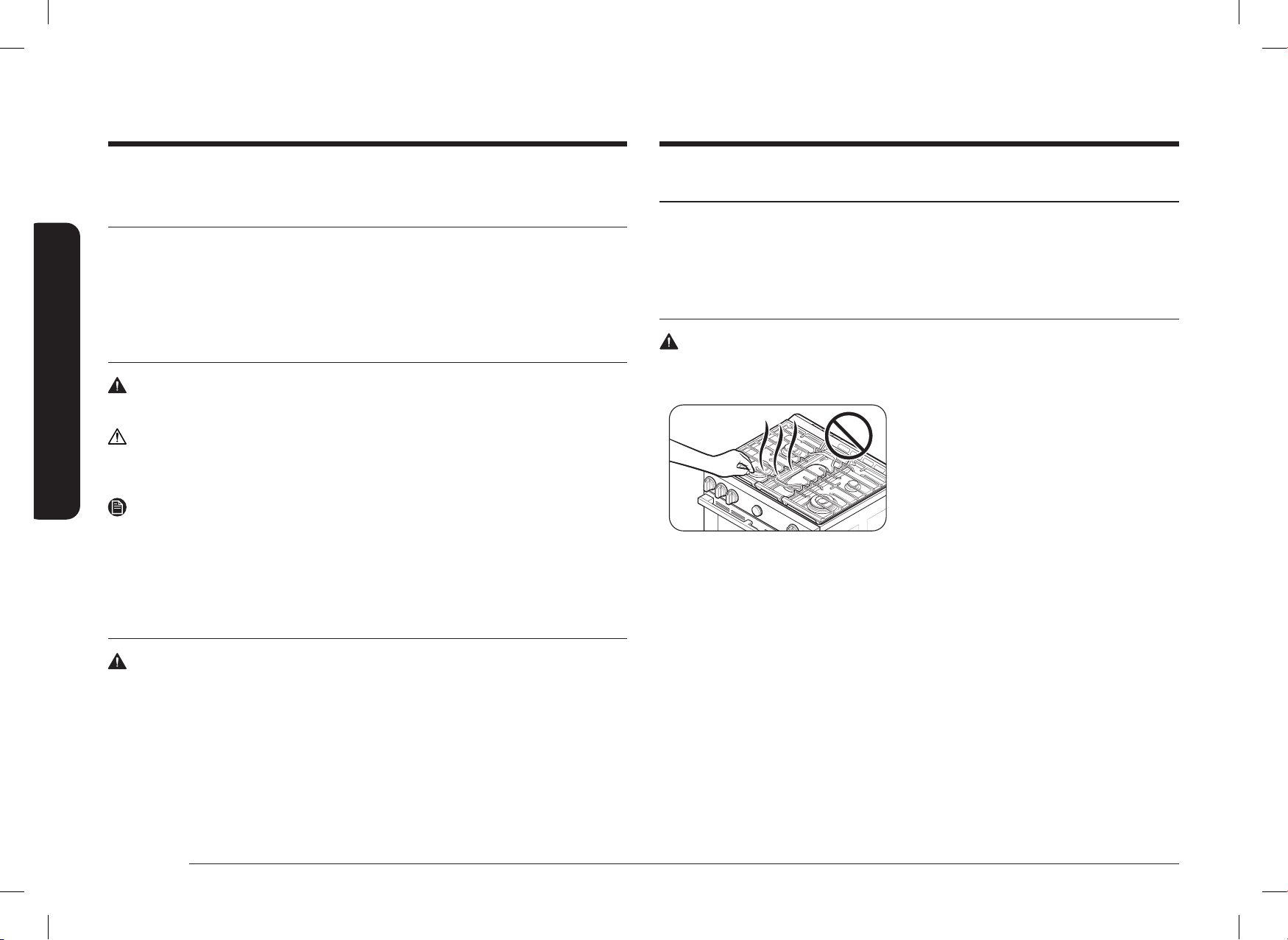
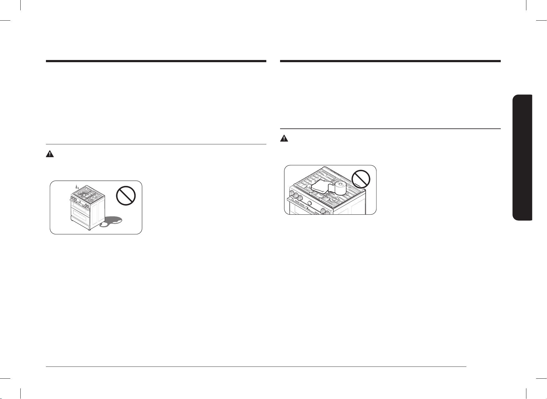
• Do not store, place, or use ammable or
combustible materials such as charcoal,
paper, plastic, pot holders, linens,
curtains, gasoline or other ammable
vapors or liquids near or inside the
range.
• Do not wear loose tting or hanging
garments while using the range.
• To avoid grease buildup, regularly clean the vents.
• Do not let pot holders or other ammable materials touch a heating element.
Do not use a towel or other bulky cloths in place of a pot holder.
• Do not use water on a grease re. To put out a grease re, turn off the heat
source and smother the re with a tight-tting lid or use a multipurpose dry
chemical or foam-type re extinguisher.
• If a grease re should occur in the oven, turn off the oven by pressing the OFF
button. Keep the oven door closed until the re goes out. If necessary, use a
multipurpose dry chemical or foam-type re extinguisher.
• Do not heat unopened food containers - buildup of pressure may cause
container to burst and result in injury.
DG68-01650A-02_IM_NSY6DG8550SRAA_EN+MES+CFR.indb 5DG68-01650A-02_IM_NSY6DG8550SRAA_EN+MES+CFR.indb 5 2024-12-03 오후 4:13:242024-12-03 오후 4:13:24

6 English
Important safety information
Important safety information
INSTALLATION SAFETY
WARNING
To reduce the risk of re, electric shock, personal injuries, and/or death, obey the
following precautions.
• Have your range installed and properly
grounded by a qualied installer,
in accordance with the installation
instructions. Any adjustment and
service should be performed only by
qualied gas range installers or service
technicians.
• Do not attempt to service, modify, or replace your range or any part of your
range unless it is specically recommended in this manual. All other service
should be referred to a qualied technician.
• Always use new exible connectors when installing a gas appliance. Do not
use old exible connectors.
• Make sure the anti-tip device is properly installed on the range. See the
installation instructions for more information.
• Due to the size and weight of the range, have two or more people move the
range.
• Remove all tape and packaging materials.
• Remove all accessories from the cooktop, oven, and/or lower drawer. Grates
and griddles are heavy. Use caution when handling them.
• Make sure no parts came loose during shipping.
• Make sure your range is correctly installed and adjusted by a qualied service
technician or installer for the type of gas (natural or LP) you will use. For
your range to utilize LP gas, the installer must replace the 5 surface burner
orices and 2 oven orices with the provided LP orice set, and reverse
the GPR adapter. These adjustments must be made by a qualied service
technician in accordance with the manufacturer’s instructions and all codes
and requirements of the authority having jurisdiction. The qualied agency
performing this work assumes the gas conversion responsibility.
ELECTRICAL AND GROUNDING SAFETY
WARNING
To reduce the risk of re, electric shock, personal injuries, and/or death, obey the
following precautions.
• Plug into a grounded 3-prong outlet.
• Do not remove the ground prong.
• Do not use an adapter or an extension
cord.
• Do not use a damaged power plug,
power cord, or loose power outlet.
• Do not modify the power plug, power cord, or power outlet in any way.
• Do not put a fuse in a neutral or ground circuit.
• Use a dedicated 240-volt, 60-Hz, 40-amp, AC, fused electrical circuit for this
range. A time-delay fuse or circuit breaker is recommended. Do not plug more
than one appliance into this circuit.
• Do not connect the ground wire to plastic plumbing lines, gas lines, or hot
water pipes.
• This range must be Earth grounded. In the event of a malfunction or
breakdown, grounding will reduce the risk of electrical shock by providing
a path for the electric current. This range is equipped with a cord having
a grounding plug. The plug must be rmly plugged into an outlet that is
properly installed and grounded in accordance with the local codes and
ordinances. If you are unsure whether your electrical outlet is properly
grounded, have it checked by a licensed electrician.
• Electrical service to the range must conform to local codes. Barring local
codes, it should meet the latest ANSI/NFPA No. 70 – Latest Revision (for the
U.S.) or the Canadian Electrical Code CSA C22.1 – Latest Revisions.
• It is the personal responsibility of the range owner to provide the correct
electrical service for this range.
DG68-01650A-02_IM_NSY6DG8550SRAA_EN+MES+CFR.indb 6DG68-01650A-02_IM_NSY6DG8550SRAA_EN+MES+CFR.indb 6 2024-12-03 오후 4:13:252024-12-03 오후 4:13:25
English 7
Important safety information
• Cabinet storage above the surface of the range should be avoided. If cabinet
storage above the range is necessary: allow a minimum clearance of 30 inches
(76.2 cm) between the cooking surface and the bottom of cabinets; or install a
range hood that projects horizontally a minimum of 5 inches (12.7 cm) beyond
the bottom of the cabinets.
COOKTOP SAFETY
WARNING
To reduce the risk of re, electric shock, personal injuries, and/or death, obey the
following precautions.
• Make sure all burners are off when not
in use.
• Do not use aluminium foil to line the
grates or any part of the cooktop.
• Do not leave burners unattended on
medium or high heat settings.
• Before igniting, make sure all burner caps are properly in place and all
burners are level.
• Always use the LITE position when igniting the burners and make sure the
burners have ignited. If ignition fails, turn the knob to OFF and wait until the
gas has dissipated.
• When you set a burner to simmer, do not turn the knob quickly. Make sure the
ame stays on.
• Do not place any objects other than cookware on the cooktop.
• This cooktop is designed to cook with a wok or wok ring attachment. If foods
are amed, they should only be amed under a ventilation hood that is on.
• Before removing or changing cookware, turn off the burners.
• Remove food and cookware immediately after cooking.
• Before removing any parts of the burner for cleaning, make sure the range is
off and completely cool.
• After cleaning the burner spreader, make sure it is completely dry before re-
assembling.
• Installation of this range must conform with local codes or, in the absence of
local codes, with the National Fuel Gas Code, ANSI Z223.1/NFPA.54, latest
edition. In Canada, installation must conform with the current Natural Gas
Installation Code, CAN/CGA-B149.1, or the current Propane Installation Code,
CAN/CGA-B149.2, and with local codes where applicable. This range has been
design-certied by ETL according to ANSI Z21.1, latest edition, and Canadian
Gas Association according to CAN/CGA-1.1, latest edition.
LOCATION SAFETY
WARNING
To reduce the risk of re, electric shock, personal injuries, and/or death, obey the
following precautions.
• This range is for indoor, household use
only. Do not install the range in areas
exposed to the weather and/or water.
• Do not install the range in a place
which is exposed to a strong draft.
• Select a level, well-constructed oor that can support the range’s weight.
Synthetic ooring, such as linoleum, must withstand 180 °F (82 °C)
temperatures without shrinking, warping, or discoloring. Do not install
the range directly over interior kitchen carpeting unless a sheet of ¼ inch
plywood or a similar insulator is placed between the range and carpeting.
• Select a location where a grounded, 3- prong outlet is easily accessible.
• If the range is located near a window, do not hang long curtains or paper
blinds on that window.
• For the range to ventilate properly, make sure the range’s vents are not
blocked or covered, and that there is enough clearance at the top, back, sides,
and underneath the range. The vents allow the necessary exhaust for the range
to operate properly with correct combustion and get the good cooking result.
• Make sure the wall coverings around the range can withstand heat up to
194 °F (90 °C) generated by the range.
DG68-01650A-02_IM_NSY6DG8550SRAA_EN+MES+CFR.indb 7DG68-01650A-02_IM_NSY6DG8550SRAA_EN+MES+CFR.indb 7 2024-12-03 오후 4:13:252024-12-03 오후 4:13:25
8 English
Important safety information
Important safety information
OVEN SAFETY
WARNING
To reduce the risk of re, electric shock, personal injuries, and/or death, obey the
following precautions.
• Do not use the oven for non-cooking
purposes such as drying clothes or
storage. Use the oven for cooking
purposes only.
• Make sure the inner portion of the split
oven-rack is in the proper position
within the outer rack.
• Make sure the oven racks are placed on the same level on each side.
• Do not damage, move, or clean the door gasket.
• Do not spray water on the oven glass while the oven is on or just after you
have turned it off.
• Do not use aluminium foil or foil liners anywhere in the oven. Do not use
aluminium foil or like material to cover any holes or passages in the oven
bottom or to cover an oven rack.
• Stand away from the oven when opening the oven door.
• Keep the oven free from grease buildup.
• When repositioning the oven racks, make sure the oven is completely cool.
• Only use cookware that is recommended for use in gas ovens.
• To avoid damaging the burner control knobs, always bake and/or broil with
the oven door closed.
• Keep oven vent ducts unobstructed. The oven vent is located below the
control box. This area could become hot during oven use. Never block this
vent or place plastic or heat-sensitive items on it.
• When using cooking or roasting bags in the oven, follow the manufacturer’s
directions.
• Make sure the spark mark on the dual burner spreader is placed beside the
electrode when it is assembled.
• Please refer to the start guide how to install the burners.
• Checking the ame quality after installing all burner. Please refer to page 25.
• To avoid carbon monoxide poisoning, do not pour water into the cooktop well
while cleaning.
• Select cookware that is designed for top-range cooking. Use cookware that is
large enough to cover the burner grates. Adjust the burner ames so that the
ames do not extend beyond the bottom of the cookware.
• To avoid cookware discoloration, deformity, and/or carbon monoxide
poisoning, do not use cookware that is exceedingly larger than the grate.
• Make sure cookware handles are turned to the side or rear of the cooktop, but
not over other surface burners.
• Stand away from the range while frying.
• Always heat frying oils slowly, and watch as they heat. If you are frying foods
at high heat, carefully watch during the cooking process. If a combination of
fats or oils is to be used during frying, mix them together before heating.
• Use a deep-fryer thermometer whenever possible. This prevents overheating
the fryer beyond the smoking point.
• Use a minimum amount of oil when shallow pan-frying or deep-frying.
Avoid cooking unthawed food or food with excessive amounts of ice.
• Before moving cookware full of fats or oils, make sure it has completely cooled.
• To prevent delayed eruptive boiling, always allow heated liquids to stand at least
20 seconds after you have turned off the burner so that the temperature in the
liquid can stabilize. In the event of scalding, follow these rst aid instructions:
1) Immerse the scaled area in cool or lukewarm water for at least 10 minutes.
2) Do not apply any creams, oils, or lotions.
3) Cover with a clean, dry cloth.
DG68-01650A-02_IM_NSY6DG8550SRAA_EN+MES+CFR.indb 8DG68-01650A-02_IM_NSY6DG8550SRAA_EN+MES+CFR.indb 8 2024-12-03 오후 4:13:252024-12-03 오후 4:13:25

English 9
Important safety information
SELF-CLEANING OVEN SAFETY
WARNING
To reduce the risk of re, electric shock, personal injuries, and/or death, obey the
following precautions.
• The self-cleaning feature operates the
oven at temperatures high enough
to burn away food soils in the oven.
The range is extremely hot during a
self-cleaning cycle. Do not touch any
surfaces of the range during a self-
cleaning cycle.
• Keep children away from the oven during a self-cleaning cycle.
• Before starting a self-cleaning cycle, remove all racks, cookware, and utensils
from the oven. Only porcelain-coated oven racks may be left in the oven.
• Before starting a self-cleaning cycle, wipe grease and food soils from the
oven.
• Do not put the lower drawer into the oven cavity when you run a self-
cleaning cycle.
• When opening the door after a self-cleaning cycle, stand away from the oven.
• If the self-cleaning cycle malfunctions, turn off the oven, disconnect the power
supply, and contact a qualied service technician.
STORAGE DRAWER SAFETY
WARNING
To reduce the risk of re, electric shock, personal injuries, and/or death, obey the
following precautions.
• Do not use the drawer for non-cooking
purposes such as drying clothes or
storage. Use the drawer for cooking
purposes only.
• Do not touch the interior drawer
surface or heating element.
• To avoid steam burns, use caution when
opening the drawer.
• Do not use aluminium foil to line the
drawer.
• Do not use the drawer in the oven.
Do not put the drawer in the oven
during a self-cleaning cycle.
• Do not leave containers of fat drippings
in or near the drawer.
DG68-01650A-02_IM_NSY6DG8550SRAA_EN+MES+CFR.indb 9DG68-01650A-02_IM_NSY6DG8550SRAA_EN+MES+CFR.indb 9 2024-12-03 오후 4:13:252024-12-03 오후 4:13:25
10 English
Dual fuel range components
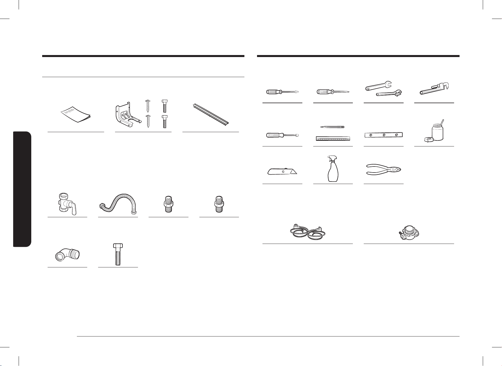
What’s in the box
Parts supplied
Template Anti Tip Bracket (1) /
Screws (4)
Filler Kit (1) & Screws (2)
• Make sure you have received all of the supplied parts shown above.
• If your range was damaged during shipping or you do not have all of the
supplied parts, contact your local retailer.
Parts needed
Gas line shut-off
valve
Flexible metal
appliance connector
½ in (ID) x 5 ft
Flare union adapter
¾ in or ½ in (NPT)
x ½ in (ID)
Flare union adapter
½ in (NPT)
x ½ in (ID)
135-degree elbow
(optional)
Lag bolt or ½-in
(OD) sleeve anchor
Dual fuel range components
Tools needed
Flat-blade
screwdriver
Phillips screwdriver Open-end or
adjustable wrench
Pipe wrench (2)
¼” Nut driver Pencil and ruler Level Pipe joint compound
Utility knife Soapy water
solution
Pliers
What’s not included
4-Wire Cord or 3-Wire Cord
(UL Approved 40 or 50 AMP)
* For Canada only
Strain Relief
(For Conduit Installation Only)
DG68-01650A-02_IM_NSY6DG8550SRAA_EN+MES+CFR.indb 10DG68-01650A-02_IM_NSY6DG8550SRAA_EN+MES+CFR.indb 10 2024-12-03 오후 4:13:262024-12-03 오후 4:13:26
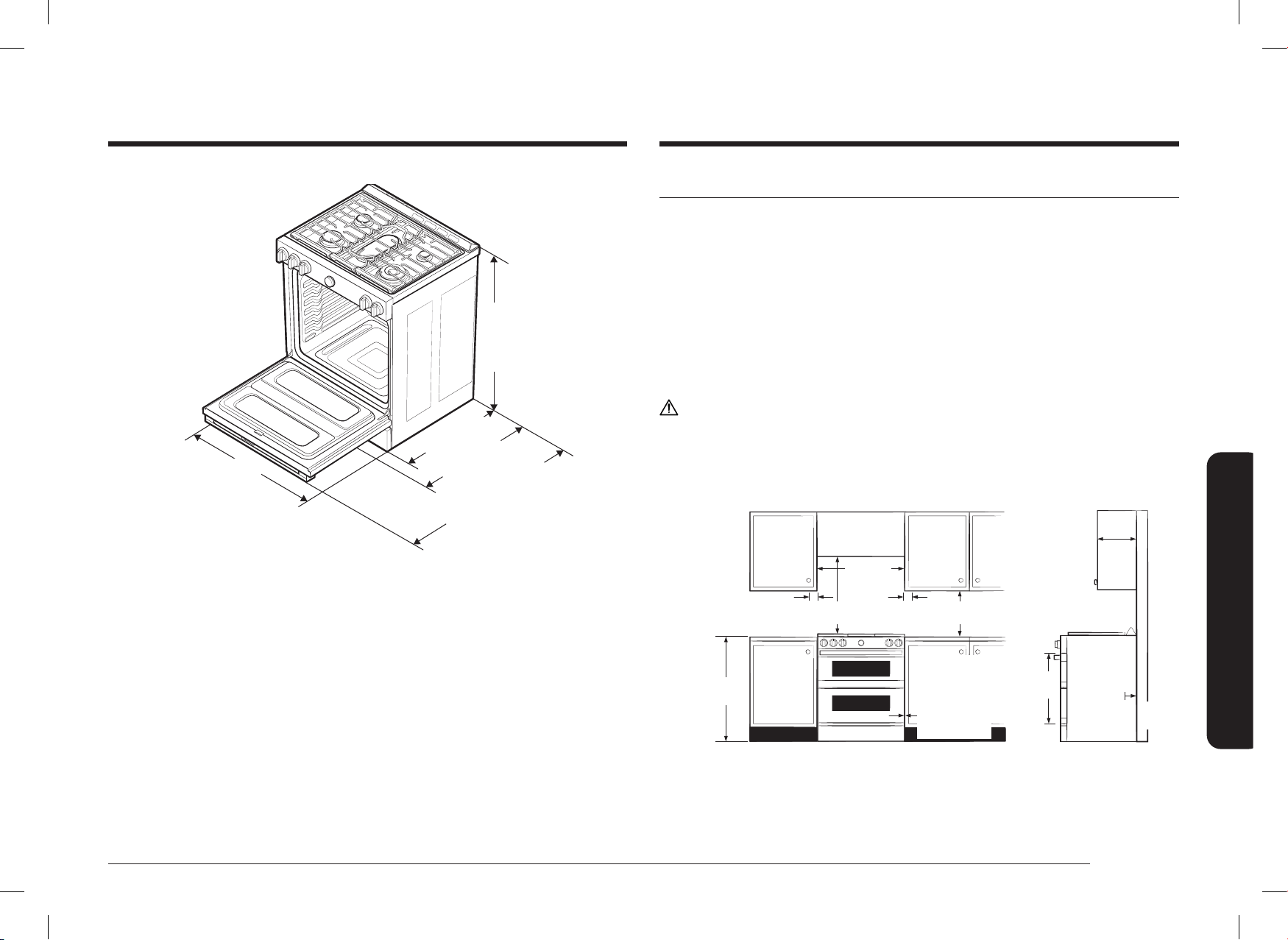
English 11
Installation requirements
36 in
(914.4 mm) Min.
36
3
/4 in
(933.5 mm) Max.
29
15
/16 in
(761.0 mm)
26
7
/
16
in
(671.7 mm)
49
1
/
4
in (1250.3 mm)
Door fully open
28
7
/
16
in
(721.8 mm)
With handle
Location requirements
Clearances and dimensions
BEFORE YOU BEGIN to install this appliance, refer to the following information,
dimensions, and clearances. Do not locate the range where it may be subject
to strong drafts. Provide adequate clearances between the range and adjacent
combustible surfaces. These dimensions must be met for safe use of the range.
The location of the electrical outlet and gas piping may be adjusted to meet the
following dimensions and clearances.
For installation in Canada, a free-standing range is not to be installed closer than
4.7 in (12 cm) from any adjacent surface.
CAUTIONN
This range has been designed to comply with the maximum allowable wood
cabinet temperature of 194 °F (90 °C). Make sure the wall covering, countertops,
and cabinets around the range can withstand the heat (up to 194 °F [90 °C])
generated by the range. If not, discoloration, delamination, or melting may occur.
13 in (33 cm)
Overhead
Cabinet
Depth
24 in
(61 cm)
Lower
Cabinet
Depth
4 in
(10.2 cm)
6 in
(15.2 cm)
Side Clearance
Above Cooking
Surface to Wall
36 in
(91.4 cm)
30 in
(76.2 cm)
18 in
(45.7 cm)
30 in
(76.2 cm)
0 in (0 cm)
Clearance
Below Cooking
Top and at Rear
and Sides of
Range
Minimum from
top of cooktop to
cabinets
24.2 in
(61.5 cm)
0 in
(0 cm)
Installation requirements
DG68-01650A-02_IM_NSY6DG8550SRAA_EN+MES+CFR.indb 11DG68-01650A-02_IM_NSY6DG8550SRAA_EN+MES+CFR.indb 11 2024-12-03 오후 4:13:272024-12-03 오후 4:13:27

12 English
Installation requirements
Installation requirements
Exception 2 : For island installation, maintain 2-½” minimum from cutout to back
edge of countertop and 4” minimum from cutout to side edges of countertop.
IMPORTANT:
To eliminate the risk of burns or re caused by reaching over heated surface units,
avoid having cabinet storage space located above the surface units.
If you have cabinet storage space over the heating elements, you can reduce the
risk by installing a range hood that projects horizontally a minimum of 5 inches
beyond the bottom of the cabinets.
Installation guide
A
36" - 36
36" - 36
3
3
/
/
4
4
"
"
(914.4 mm -
(914.4 mm -
933.5 mm)
933.5 mm)
26
26
7
7
/
/
16
16
"
"
(671.7 mm)
(671.7 mm)
29
29
15
15
/
/
16
16
"
"
(761.0 mm)
(761.0 mm)
25"
25"
3"
3"
24"
24"
24"
24"
3"
3"
35
35
7
7
/
/
8
8
"
"
A: Cabinet opening 30" (76.2 cm)
IMPORTANT: If your cabinet have height over 36
3
/4", this range cannot be
installed without supporting unit like hard block.
CAUTION
DO NOT install the oven so that the door is ush with the cabinet.
For OTR over Gas Stove, please follow local GAS CODE.
Minimum dimensions
WARNING
If overhead cabinets are provided, a range hood should also be provided that
projects horizontally a minimum of 5 in (12.7 cm) beyond the front of the cabinets.
This will dissipate any heat buildup in the overhead cabinets to prevent death,
personal injury, and/or re hazard. The ventilating hood must be constructed of
sheet metal not less than 0.0122” thick. Install above the cooktop with a clearance
of not less than ¼” between the hood and the underside of the combustible
material or metal cabinet. The hood must be at least as wide as the appliance
and centered over the appliance. Clearance between the cooking surface and the
ventilation hood surface must never be less than 24 inches.
Exception 1 : Installation of a listed microwave oven or cooking appliance over the
cooktop shall conform to the installations packed with that appliance.
• 30-in (76.2-cm) minimum clearance between the top of the cooking surface
and the bottom of an unprotected wood or metal cabinet; or If no 30-in
(76.2-cm) minimum clearance, 24-in (61-cm) minimum when the bottom of
the wood or metal cabinet is protected by not less than 0.25-in (0.64-cm)
ame-retardant millboard covered with not less than no. 28 MSG sheet steel,
0.015-in (0.038-cm) stainless steel, 0.024-in (0.061-cm) aluminum, or 0.020-in
(0.051-cm) copper.
• 18-in (45.7-cm) minimum between the countertop and the adjacent cabinet
bottom.
DG68-01650A-02_IM_NSY6DG8550SRAA_EN+MES+CFR.indb 12DG68-01650A-02_IM_NSY6DG8550SRAA_EN+MES+CFR.indb 12 2024-12-03 오후 4:13:272024-12-03 오후 4:13:27
English 13
Installation requirements
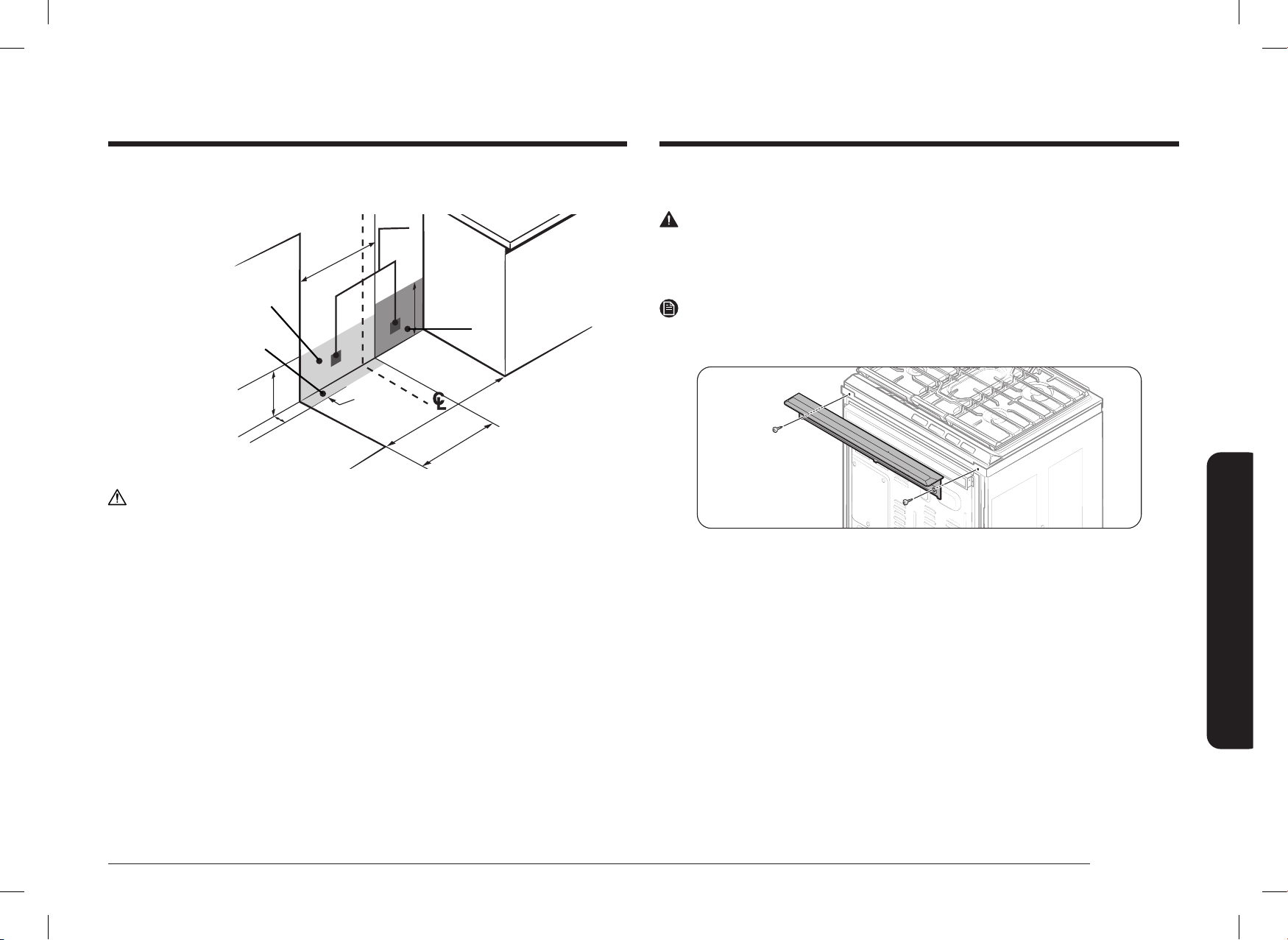
Optional rear ller kit
WARNING
Used to ll gap between the range back and wall. Adds a ller strip to the rear
of the range. This kit can only be used when the opening in the countertop is 25"
deep.
NOTE
If the countertop depth is greater than 25", there will be a gap between the ller
kit and the back wall.
Recommended locations for gas piping and electrical outlets
(For models NSY6
**
8
*
5
***
)
Recommended area
Recommended area
for 120V/240V or
for 120V/240V or
120V/208V electrical
120V/208V electrical
outlet on rear wall
outlet on rear wall
Recommended
Recommended
position
position
30 in (76.2 cm)
30 in (76.2 cm)
Cabinet Opening
Cabinet Opening
17 in (43.2 cm)
17 in (43.2 cm)
12 in
12 in
(30.5 cm)
(30.5 cm)
Gas Wall Area
Gas Wall Area
Recommended area for
Recommended area for
through-the-wall and through-
through-the-wall and through-
the-oor connection of gas
the-oor connection of gas
pipe stub and shut-off valve.
pipe stub and shut-off valve.
Gas Floor Area
Gas Floor Area
17 in
17 in
(43.2 cm)
(43.2 cm)
9 in
9 in
(22.9 cm)
(22.9 cm)
2 in
2 in
(5.1 cm)
(5.1 cm)
CAUTION
You must use the rear ller kit to install the range in a freestanding cutout cabinet.
For more information, see “Optional rear ller kit” as shown below.
DG68-01650A-02_IM_NSY6DG8550SRAA_EN+MES+CFR.indb 13DG68-01650A-02_IM_NSY6DG8550SRAA_EN+MES+CFR.indb 13 2024-12-03 오후 4:13:272024-12-03 오후 4:13:27
14 English
Installation requirements
Installation requirements
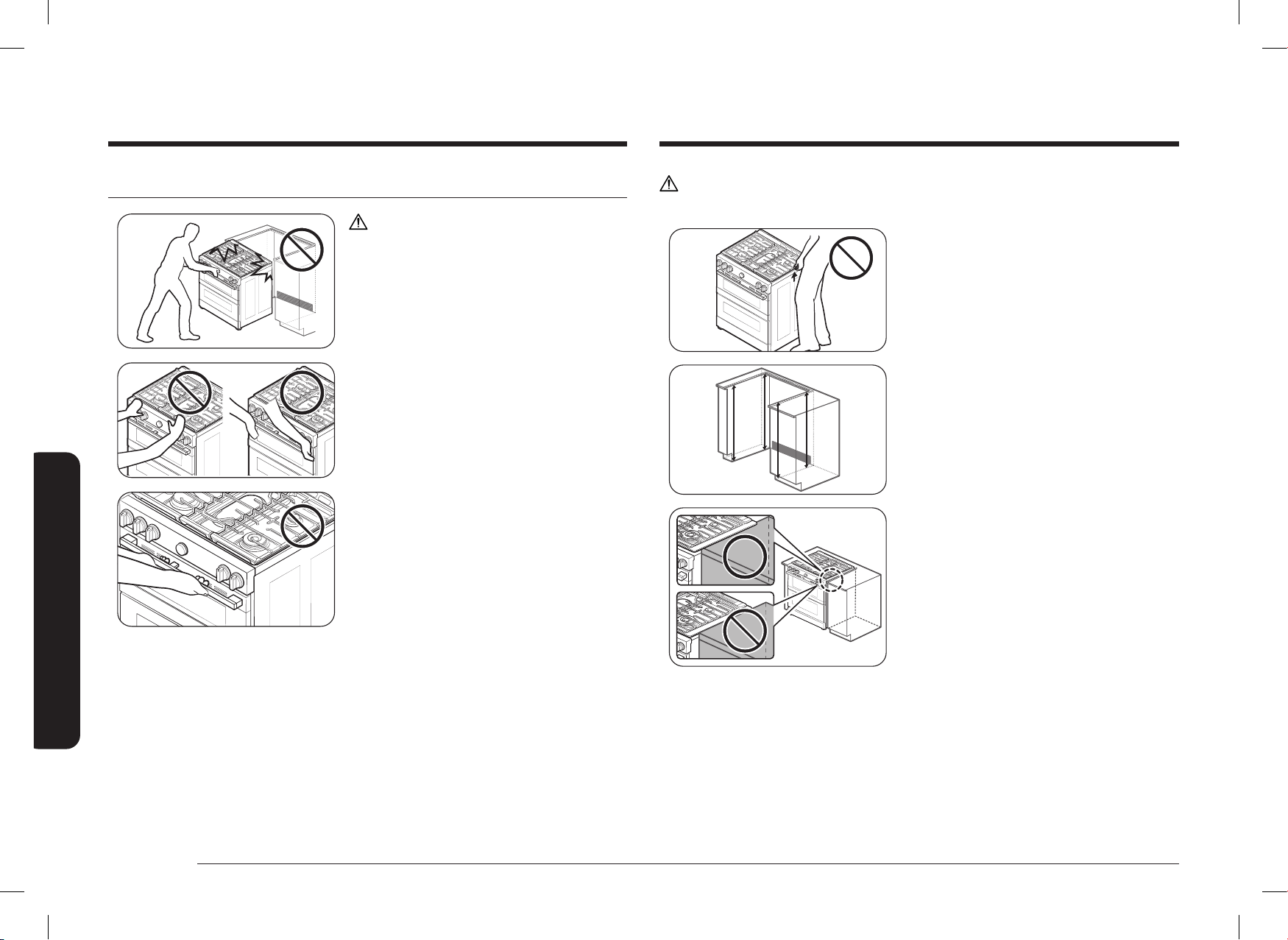
CAUTION
Do NOT lift or handle the unit by the cooktop frame.
Fig. 1
Fig. 1
1. The counter top around the cut-out
should be at and leveled (See hatched
area on Fig. 1).
2. Before installing the unit, measure
the heights of the two cabinet sides
(C1
~
C4), front and back (See Fig. 1)
from the oor to the top of the counter.
3. Level the range using the four leveling
legs so that the height from the oor
to the underside of the cooktop frame
is greater than the tallest cabinet
measurement by at least 1/16".
4. Slide the unit into the cabinet (DO NOT
PUSH THE UNIT HARD). Make sure the
center of the unit aligns with the center
of the cabinet cut-out.
5. The metal ange under each side of
the cooktop MUST be placed over the
cabinet countertop for proper unit
support. The cooktop should NOT rest
directly on the countertop or else it
could cause damage to the cooktop
voiding the warranty. Level the unit if
needed.
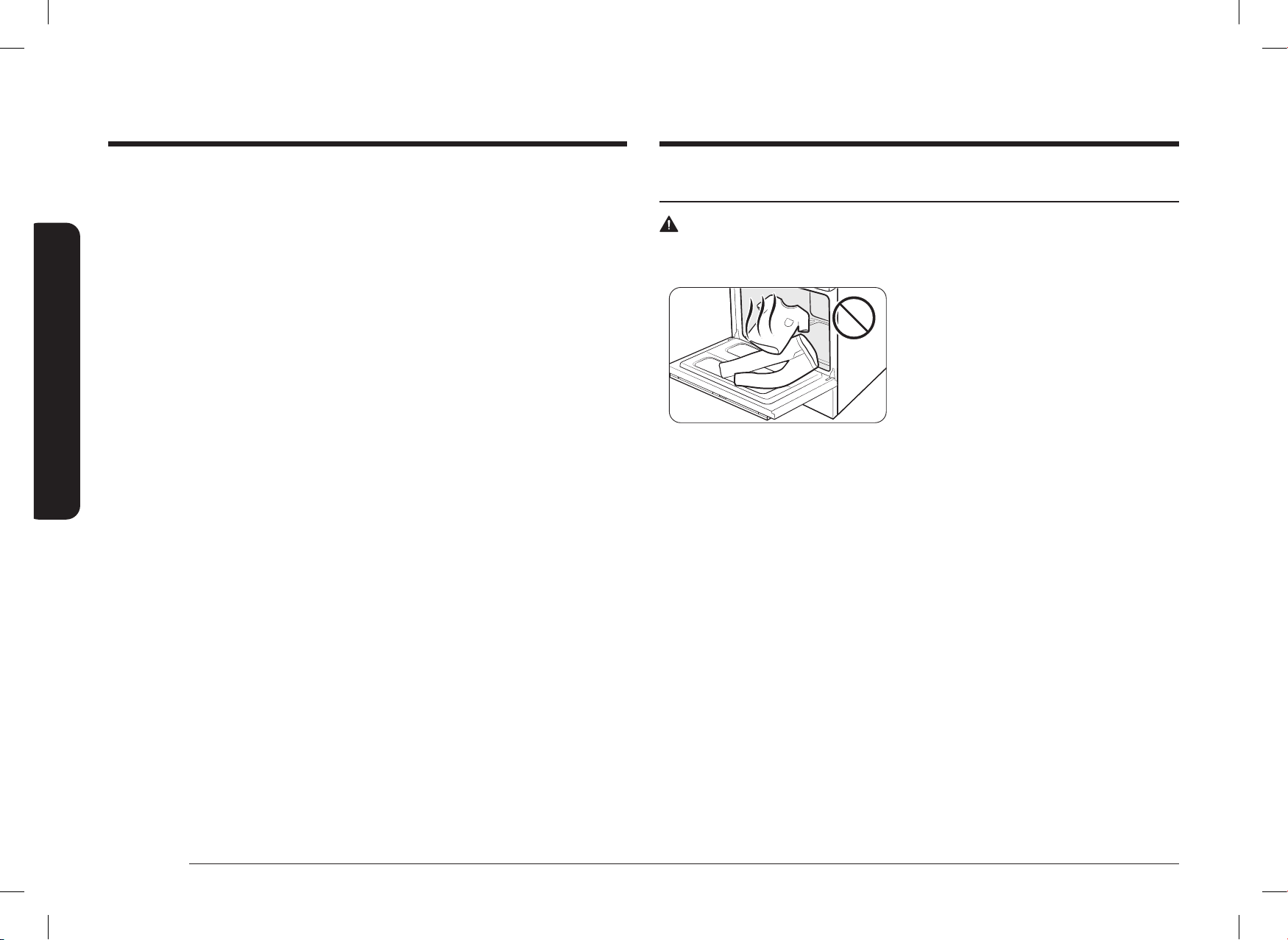
To avoid breakage
CAUTION
Please DO NOT push the unit strongly when
you install. These actions can cause the
damage to the unit.
Please DO NOT push the burner knobs when
installing the range.
(Grasp the L/R door area to push the unit.)
Do not grasp and push handle when you
install.
DG68-01650A-02_IM_NSY6DG8550SRAA_EN+MES+CFR.indb 14DG68-01650A-02_IM_NSY6DG8550SRAA_EN+MES+CFR.indb 14 2024-12-03 오후 4:13:282024-12-03 오후 4:13:28
English 15
Installation requirements
Special gas requirements (gas models sold in Massachusetts)
COMMONWEALTH OF MASSACHUSETTS REQUIREMENTS:
WARNING
• Gas leaks may occur in your system, creating a dangerous situation.
- Gas leaks may not be detected by smell alone.
- Gas suppliers recommend you purchase and install a UL-approved
gas detector. Gas detector should be installed in accordance with the
manufacturers instructions.
• Range must be installed by a qualied plumber or gas tter by the State of
Massachusetts.
• A T-handle manual gas valve MUST be installed in the gas supply line to your
range.
• If a exible gas connector is used to install your range, multiple exible gas
lines must not be connected in series.
Gas requirements
Provide adequate gas supply
This range is designed to operate at a pressure of 5 in (13 cm) of water column on
natural gas or 10 in (25 cm) of water column on LP gas (propane or butane).
Make sure you are supplying your range with the type of gas for which it is
designed.
Do not attempt to convert the appliance from the gas specied in this manual to a
different gas without consulting the gas supplier.
This range is convertible for use on natural or propane gas. If you decide to use
this range on LP gas, conversion must be made by a qualied LP installer before
attempting to operate the range.
For proper operation, the pressure of natural gas supplied to the regulator must be
between 5 in and 13 in (13 cm and 33 cm) of water column.
For LP gas, the pressure supplied must be between 10 in and 13 in (25 cm and
33 cm) of water column.
When checking for proper operation of the regulator, the inlet pressure must be at
least 1 in (2.5 cm) greater than the operating (manifold) pressure as given.
The pressure regulator located at the inlet of the range manifold must remain in
the supply line regardless of whether natural or LP gas is being used.
A exible-metal appliance connector used to connect the range to the gas supply
line should have an I.D. of 0.5 in (1.3 cm) and be 5 ft (152 cm) in length for ease of
installation. In Canada, exible connectors must be single-wall metal connectors no
longer than 6 ft (183 cm) in length.
Do not kink or damage the exible metal tubing when moving the range.
DG68-01650A-02_IM_NSY6DG8550SRAA_EN+MES+CFR.indb 15DG68-01650A-02_IM_NSY6DG8550SRAA_EN+MES+CFR.indb 15 2024-12-03 오후 4:13:282024-12-03 오후 4:13:28

16 English
Installation requirements
Installation requirements
Grounding
• All ranges must be grounded for personal safety.
• All gas models have a power cord with an equipment-grounding conductor
and a grounding plug.
• Do not use a damaged power plug or loose wall outlet.
• Do not use an extension cord or adapter with this appliance.
• Do not, under any circumstances, cut, modify, remove, or otherwise defeat the
grounding (third) prong from the power cord. If the plug and the outlet do not
match or you have any doubt, have a qualied electrician install the proper
outlet.
The customer should have the wall receptacle and circuit checked by a
qualied electrician to make sure the receptacle is properly grounded.
Ground Fault Circuit Interrupters (GFCIs) are not required or recommended for
gas range receptacles.
• NEVER connect ground wire to plastic plumbing lines, gas lines, or water
pipes.
CAUTION
Failure to follow these instructions can result in death, re, or electrical shock.
Additional installation requirements for mobile homes
The installation of appliances designed for mobile home installation must conform
with the Manufactured Home Construction and Safety Standard, Title 24 CFR,
Part 3280 (formerly the Federal Standard for Mobile Home Construction and
Safety, Title 24, HUD, Part 280) or, when such standard is not applicable, the
Standard for Manufactured Home Installations, latest edition (Manufactured Home
Sites, Communities and Set-Ups), ANSI A225.1, latest edition, or with local codes. In
Canada, mobile home installation must be in accordance with the current CAN/CSA
Z240/MH Mobile Home Installation Code.
Electrical requirements
WARNING
To reduce the risk of re, electric shock, or personal injury:
All ranges
• Do not use an extension cord or adapter plug with this range.
• This range must be properly grounded.
• Check with a qualied electrician if you are in doubt as to whether your range
is properly grounded.
• Do not modify the plug provided with your range—if it doesn’t t the outlet,
have a proper outlet installed by a qualied electrician.
• All wiring and grounding must be done in accordance with local codes or, in
the absence of local codes, with the National Electrical Code, ANSI/NFPA
No. 70 – Latest Revision (for the U.S.) or the Canadian Electrical Code CSA
C22.1 – Latest Revisions and local codes and ordinances.
• Wiring diagram is located on the back of the range. (Inside of the cover back
wire)
• This range is equipped with an electronic ignition system that will not operate
if plugged into an outlet that is not properly polarized.
Gas models
• Canada gas models are equipped with a power cord with an equipment-
grounding conductor and a grounding plug.
(The power cord is not provided in US model.)
• A 240-Volt, 60-Hz, AC, approved electrical service with 40-amp circuit breaker
or time-delay fuse is required for all U.S. and Canadian models.
• Check for ¾-in (1.9-cm) UL-listed strain relief where the power cord comes out
of the range cabinet.
• Do not reuse a power supply cord from an old range or other appliance.
• The power cord electric supply wiring must be retained at the range cabinet
with a suitable UL-listed strain relief.
• A time-delay fuse or circuit breaker is also recommended.
DG68-01650A-02_IM_NSY6DG8550SRAA_EN+MES+CFR.indb 16DG68-01650A-02_IM_NSY6DG8550SRAA_EN+MES+CFR.indb 16 2024-12-03 오후 4:13:282024-12-03 오후 4:13:28

English 17
Installation instructions
Installation instructions
This appliance must be supplied with
the proper voltage and frequency, and
connected to an individual properly
grounded branch circuit, protected by a
circuit breaker or fuse having amperage
as specied on the rating plate. The rating
plate is located above the drawer on the
oven frame.
We recommend you have the electrical
wiring and hookup of your range connected
by a qualied electrician. After installation,
have the electrician show you where your
main range disconnect is located.
Check with your local utilities for electrical
codes which apply in your area. Failure
to wire your oven according to governing
codes could result in a hazardous condition.
If there are no local codes, your range
must be wired and fused to meet the
requirements of the National Electrical Code,
ANSI/NFPA No. 70–Latest Edition. You can
get a copy by writing:
National Fire Protection Association
Batterymarch Park
Quincy, MA 02269
Effective January 1, 1996, the National Electrical Code requires that new
construction (not existing) utilize a 4-conductor connection to an electric range.
When installing an electric range in new construction, follow Steps 2 and 3 for
4-wire connection.
You must use a 3-wire or 4-wire, single-phase A.C. 208Y/120 Volt or 240/120 Volt,
60 hertz electrical system.
If the electrical service provided does not meet the above specications, have a
licensed electrician install an approved outlet.
Installing your dual fuel range
IMPORTANT:
Please read the following instructions, as well as the Important Safety Instructions
section at the front of this manual, completely and carefully BEFORE installing
and/or operating the gas range. Improper installation, adjustment, service, or
maintenance can cause personal injury or property damage.
NOTE
To order parts or accessories, contact your
local retailer or refer to the last page.
NOTE
To ensure proper installation, we strongly
recommend that you hire a professional
installer.
Step 1. Unpack the range
Remove all packaging materials. Failure to remove packaging materials could
result in damage to the appliance.
Inventory all loose parts against the Parts supplied components listed on page 10.
Check for shipping damage and/or missing parts. Any damage and/or missing
parts should be reported to your local retailer.
Step 2. Meeting electrical connection requirements
CAUTION
For personal safety, do not use an extension cord with this appliance. Remove
house fuse or open circuit breaker before beginning installation.
DG68-01650A-02_IM_NSY6DG8550SRAA_EN+MES+CFR.indb 17DG68-01650A-02_IM_NSY6DG8550SRAA_EN+MES+CFR.indb 17 2024-12-03 오후 4:13:282024-12-03 오후 4:13:28
18 English
Installation instructions
Installation instructions
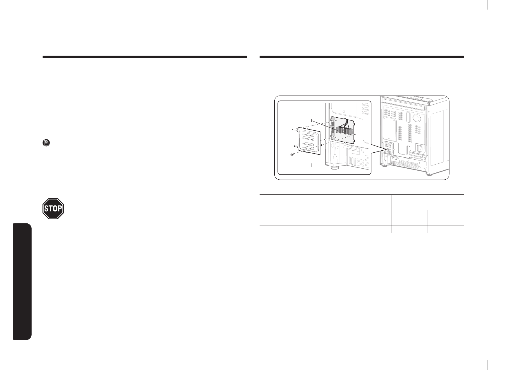
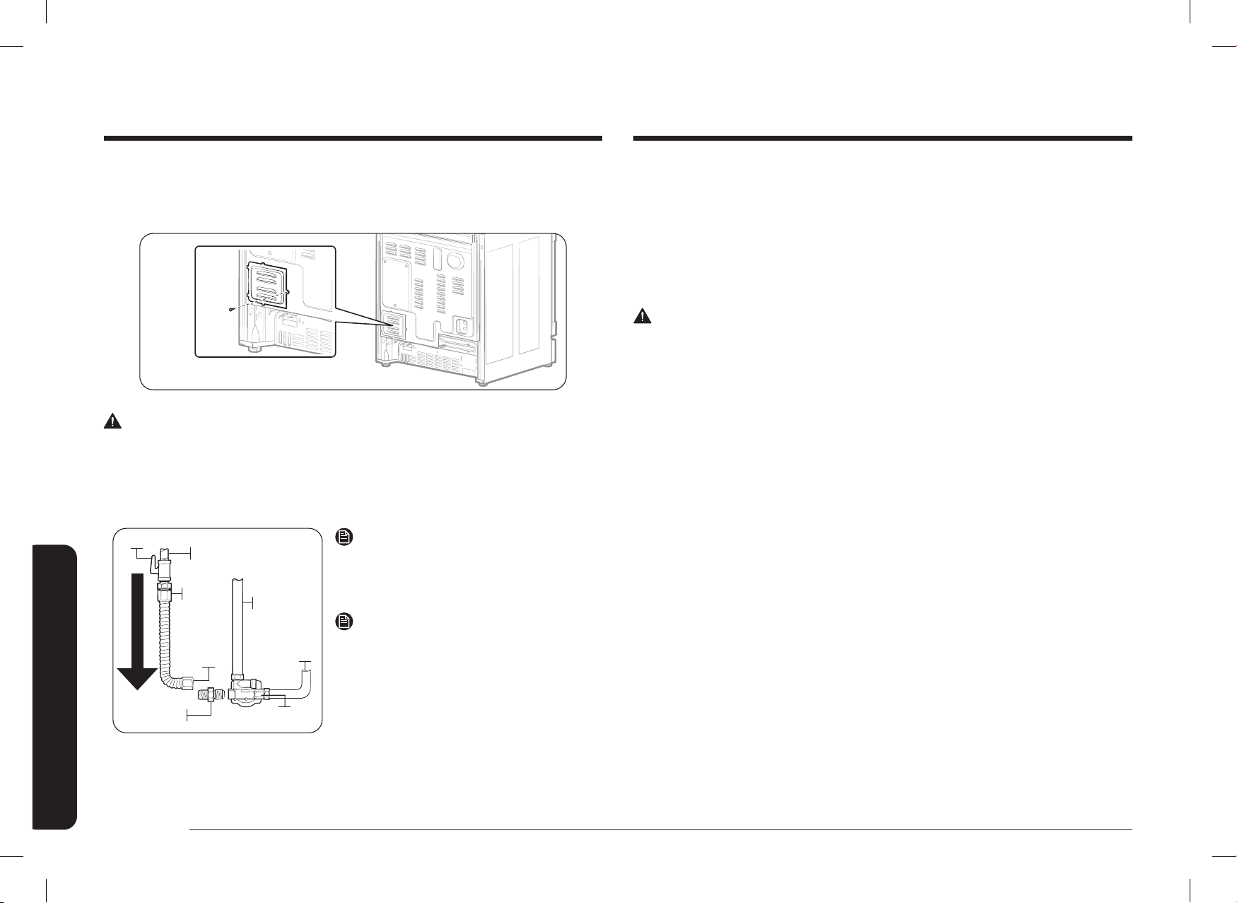
Step 3. Accessing the power cord connection
Remove the rear access cover and loosen the screw with a screwdriver.
The terminal block will then be accessible.
Access cover
Terminal block
Specied power-supply-cord kit rating
Range rating, watts
Specied rating
of power-supply-
cord kit, amperes
Diameter (inches) of range
connection opening
120/240
volts 3-wire
120/208
volts 3-wire
Power cord Conduit
8750 - 16500 7801 - 12500 40 or 50A 1 ⅜" 1 ⅛"
Use only a 3-conductor or a 4-conductor UL-listed range cord. These cords may be
provided with ring terminals on wire and a strain relief device.
A range cord rated at 40 amps with 125/250 minimum volt range is required.
A 50 amp range cord is not recommended but if used, it should be marked for
use with nominal 1 ⅜" diameter connection openings. Care should be taken to
center the cable and strain relief within the knockout hole to keep the edge from
damaging the cable.
• Because range terminals are not accessible after range is in position, exible
service conduit or cord must be used.
NOTE
• If conduit is being used, go to Step 5 on pages 20
~
21.
• If the power connection is plugged in improperly, the following message
appears on the display.
- LCD, PMOLED : Wire installation fail
- LED : bAd LinE
• Reconnect the power connection properly, and the message disappears.
ALL NEW BRANCH-CIRCUIT CONSTRUCTIONS, MOBILE HOMES,
RECREATIONAL VEHICLES AND INSTALLATIONS WHERE LOCAL
CODES DO NOT ALLOW GROUNDING THROUGH NEUTRAL, REQUIRE A
4-CONDUCTOR UL-LISTED RANGE CORD.
DG68-01650A-02_IM_NSY6DG8550SRAA_EN+MES+CFR.indb 18DG68-01650A-02_IM_NSY6DG8550SRAA_EN+MES+CFR.indb 18 2024-12-03 오후 4:13:292024-12-03 오후 4:13:29
English 19
Installation instructions
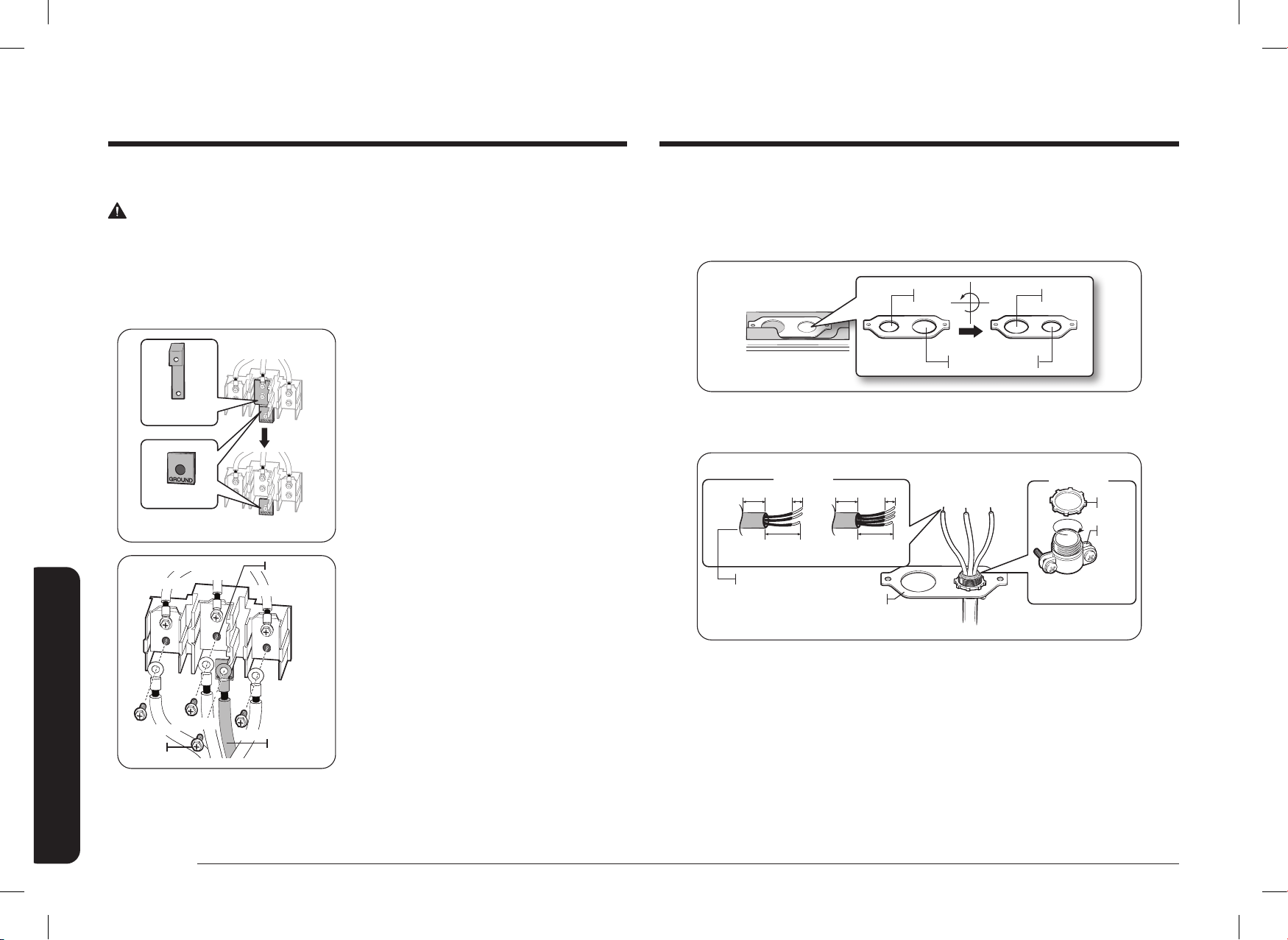
Ground strap
Neutral
terminal
Black
White
Red
Black
White
Red
1. Remove the 3 lower terminal screws
from the terminal block.
2. Insert the 3 terminal screws through
each power cord terminal ring and into
the lower terminals of the terminal
block. Be certain that the center wire
(white/neutral) is connected to the
center lower position of the terminal
block.
3. Tighten screws securely into the
terminal block. DO NOT remove the
ground strap connection.
4. Go to step 6 on page 22 and proceed
with the installation.
Step 4. Installing the power cord
For power cord installations, hook the strain relief over the power cord hole (1 ⅜")
located below the rear of the drawer body. Insert the power cord through the
strain relief and tighten the device.
Strain relief
Power cord
Conduit connection
plate
• You must install the power cord with a strain relief.
• Attach the strain relief to the 1 ⅜" opening in conduit connection plate.
Installing a 3-wire power cord
WARNING
The neutral or ground wire of the power cord must be connected to the neutral
terminal located in the center of the terminal block. The power leads must be
connected to the lower left and the lower right terminals of the terminal block.
DG68-01650A-02_IM_NSY6DG8550SRAA_EN+MES+CFR.indb 19DG68-01650A-02_IM_NSY6DG8550SRAA_EN+MES+CFR.indb 19 2024-12-03 오후 4:13:292024-12-03 오후 4:13:29
20 English
Installation instructions
Installation instructions
Step 5. Installing the conduit
Remove the conduit connection plate from the rear of the drawer body and rotate
it as shown below.
The conduit hole (1 ⅛") must be used.
1⅛" 1⅜"
1⅛"1⅜"
1. Prepare the conduit cord shown in Figure 1.
2. Install the conduit cord as shown in Figure 2.
Conduit connection plate
Strain relief
Ring
Body
Figure 2Figure 2
1"
3½"
⅜" 1"
3½"
3 wire3 wire 4 wire4 wire
Knockout surface
Figure 1Figure 1
⅜"
For conduit installations, insert the strain relief (not included) into the conduit
hole (1 ⅛"). Then thread the conduit cord through the body of the strain relief and
fasten the ring. Reinstall the bracket.
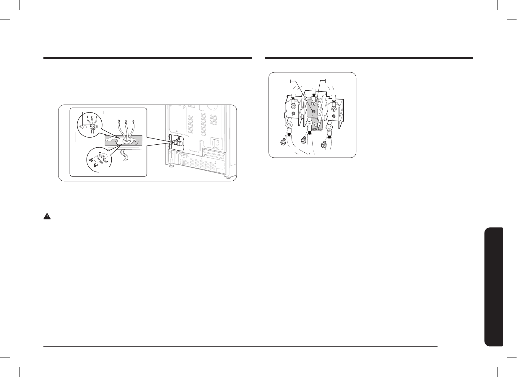
Installing a 4-wire power cord
WARNING
The neutral wire of the supply circuit must be connected to the neutral terminal
located in the lower center of the terminal block. The power leads must be
connected to the lower left and the lower right terminals of the terminal block. The
4th grounding lead must be connected to the frame of the range with the ground
plate and the ground screw.
Ground strap
Ground plate
Ground
screw
Neutral
terminal
Ground wire
(Green)
White
Black
Red
Black
White
Red
1. Remove the 3 lower terminal screws
from the terminal block. Remove the
ground screw and ground plate and
retain them.
2. Cut and discard the ground strap.
Do not discard any screws.
3. Insert the one ground screw into the
power cord ground wire terminal ring,
through the ground plate, and into the
frame of the range.
4. Insert the 3 terminal screws (removed
earlier) through each power cord
terminal ring and into the lower
terminals of the terminal block.
Be certain that the center wire (white/
neutral) is connected to the center
lower position of the terminal block.
Tighten screws securely into the
terminal block.
5. Go to step 6 on page 22 and proceed
with the installation.
DG68-01650A-02_IM_NSY6DG8550SRAA_EN+MES+CFR.indb 20DG68-01650A-02_IM_NSY6DG8550SRAA_EN+MES+CFR.indb 20 2024-12-03 오후 4:13:302024-12-03 오후 4:13:30

English 21
Installation instructions
Installing a 4-wire conduit
• Aluminum building wire may be used but it must be rated for the correct
amperage and voltage to make the connection. Connect wires according to this
Step 4 depending on the number of wires.
• Wire used, location and enclosure of splices, etc., must conform to good wiring
practices and local codes.
Ground strap
Ground plate
White
Black
Red
Neutral
terminal
Ground wire
(Green)
Wire
tips
White
Black
Red
1. Loosen the 3 lower terminal screws
from the terminal block. Remove the
ground screw and ground plate and
retain them.
2. Cut and discard the ground strap.
Do not discard any screws.
3. Insert the ground bare wire tip between
the range frame and the ground plate
(removed earlier) and secure it in
place with the ground screw (removed
earlier).
4. Insert the bare wire (white/neutral)
tip through the bottom center of the
terminal block opening.
5. Insert the two side bare wire tips into
the lower left and the lower right
terminal block openings.
6. Tighten the screws until the wire is
rmly secured (35 to 50 inch-lbs.).
Do not over-tighten the screws since it
could damage the wires.
7. Go to step 6 and proceed with the
installation.
Installing a 3-wire conduit
• Aluminum building wire may be used but it must be rated for the correct
amperage and voltage to make the connection. Connect wires according to
Step 4 depending on the number of wires.
• Wire used, location and enclosure of splices, etc., must conform to good wiring
practices and local codes.
White
Black
Red
Ground
strap
Neutral
terminal
Wire tips
Red
White
Black
1. Loosen the 3 lower terminal screws
from the terminal block.
2. Insert the center bare wire (white/
neutral) tip through the bottom center
terminal block opening. On certain
models, the wire will need to be
inserted through the ground strap
opening and then into the bottom
center block opening.
3. Insert the two side bare wire tips into
the lower left and the lower right
terminal block openings.
4. Tighten the screws until the wire is
rmly secured (35 to 50 inch-lbs.).
Do not over-tighten the screws since it
could damage the wires.
5. Go to step 6 on page 22 and proceed
with the installation.
DG68-01650A-02_IM_NSY6DG8550SRAA_EN+MES+CFR.indb 21DG68-01650A-02_IM_NSY6DG8550SRAA_EN+MES+CFR.indb 21 2024-12-03 오후 4:13:302024-12-03 오후 4:13:30
22 English
Installation instructions
Installation instructions
Step 7. Connect the range to gas supply
Shut off the main gas supply valve before disconnecting the old range and leave
it off until the new hookup has been completed. Don’t forget to relight the pilot on
other gas appliances when you turn the gas back on.
Because hard piping restricts movement of the range, the use of a CSA
International-certied exible metal appliance connector is recommended unless
local codes require a hard-piped connection.
WARNING
• If the information in this manual is not followed exactly, a re or explosion
may result, causing death, personal injury, or property damage.
- Do not store or use gasoline or other ammable vapors and liquids in the
vicinity of this or any other appliance.
- WHAT TO DO IF YOU SMELL GAS:
• DO NOT light a match, candle, or cigarette.
• DO NOT try to light any appliance.
• DO NOT touch any electrical switch.
• DO NOT use any phone in your building.
• Clear the room, building, or area of all occupants.
• Immediately call your gas supplier from a neighbor’s phone. Follow the gas
supplier’s instructions.
• If you cannot reach your gas supplier, call the re department.
- Installation and service must be performed by a qualied installer, service
agency, or gas supplier.
Step 6. Replacing the access cover
Replace the access cover on the range back. To replace the wire cover, insert
double projections in the pockets located below the opening and tighten the screw.
WARNING
Do not exceed 25 ft-lbs of torque when making gas line connections.
Overtightening may crack the pressure regulator resulting in a gas leak.
Flexible connector hookup
Installer: Inform the consumer of the location of the gas shut-off valve.
Adapter
Flex
Connector
(6-ft max.)
Adapter
Gas Shut-Off Valve
0.5-in or 0.75-in Gas Pipe
Tubing Line
to Oven
Burner
Control Valve
Gas Flow into Range
Pressure
Regulator
Tubing Line
to Cooktop
Control
Manifold
NOTE
If your area requires a rigid pipe hookup,
contact a qualied installer, service agency,
or gas supplier.
NOTE
The gas shut-off valve should be installed
in an accessible location in the gas piping,
external to the appliance, for the purpose
of turning on or shutting off the gas to the
appliance.
DG68-01650A-02_IM_NSY6DG8550SRAA_EN+MES+CFR.indb 22DG68-01650A-02_IM_NSY6DG8550SRAA_EN+MES+CFR.indb 22 2024-12-03 오후 4:13:302024-12-03 오후 4:13:30

English 23
Installation instructions
Step 8. Convert to LP gas (optional)
All new gas ranges are shipped from the factory set up to use natural gas.
Any Samsung gas range can be converted to use LP gas. Refer to page 57 in the
User Manual to contact a qualied service technician.
The conversion process should only be performed by a qualied LP gas installer.
Conversion instructions and LP orices will be supplied with the LP conversion kit.
The conversion to LP requires all burner orices to be changed (5 surface burners).
In addition, the nozzle on the gas pressure regulator needs to be reversed. All
replaced orices must be left with the consumer, including the instructions and
retrot sizes and orice indication.
Checking the ame quality all burner after converting to LP gas.
Never use an old connector when installing a new range. If the hard-piping method
is used, you must carefully align the pipe; the range cannot be moved after the
connection is made.
To prevent gas leaks, apply pipe-joint compound or wrap pipe-thread tape with
Teon on all male (external) pipe threads.
1. Install a manual gas line shut-off valve in the gas line in an easily accessed
location outside of the range.
Make sure everyone operating the range knows where and how to shut off
the gas supply to the range.
2. Install male 0.5-in (1.3-cm) are union adapter to the 0.5-in (1.3-cm) NPT
internal thread at the regulator inlet. Use a backup wrench on the regulator
tting to avoid damage.
When installing the range from the front, remove the 90 ° elbow for easier
installation.
3. Install male 0.5-in (1.3-cm) or 0.75-in (1.9-cm) are union adapter to the NPT
internal thread of the manual shut-off valve, taking care to back up the shut-
off valve to keep it from turning.
4. Connect exible metal appliance connector to the adapter on the range.
Position range to permit connection at the shut-off valve.
5. When all connections have been made, make sure all range controls are in the
off position and turn on the main gas supply valve. Use a liquid leak detector
at all joints and connections to check for leaks in the system.
WARNING
To prevent death, personal injury, explosion, and/or re hazard, DO NOT use a
ame to check for gas leaks.
When using test pressures greater than ½ psig to pressure-test the gas supply
system of the residence, disconnect the range and individual shut-off valve from
the gas supply piping. When using test pressures of ½ psig or less to test the gas
supply system, simply isolate the range from the gas supply system by closing the
individual shut-off valve.
DG68-01650A-02_IM_NSY6DG8550SRAA_EN+MES+CFR.indb 23DG68-01650A-02_IM_NSY6DG8550SRAA_EN+MES+CFR.indb 23 2024-12-03 오후 4:13:302024-12-03 오후 4:13:30

24 English
Installation instructions
Installation instructions
Step 10. Plug in and place
WARNING
BEFORE OPERATING OR TESTING, follow the grounding requirements on pages
15
~
16 in this manual. Improper connection of the grounding plug can result in a
risk of electric shock.
• All Dual Fuel ranges come with a power cord. The power cord is connected to
the rear of the range. Please review "Electrical requirements" on pages
15
~
16.
• The electrical system, including the power cord, is preinstalled and prewired at
the factory. Altering any part of this system may result in a short or overload.
1. Plug in the power cord. Make sure the outlet meets local or national electrical
codes as referenced on pages 15
~
16.
2. Slide the range into place.
3. Check the gas supply line to make sure it did not get damaged and it stayed
connected during positioning.
4. Check to make sure the back leg of the range has slid into the anti-tip bracket.
Carefully tip the range forward to ensure that the anti-tip bracket engages the
back brace and prevents tip-over.
Step 9. Install the anti-tip device
WARNING
To reduce the risk of tipping, the appliance must be secured by properly installing
the anti-tip device packed with the appliance.
• All ranges can tip, resulting in personal injury.
• Tipping ranges can cause burns from spills, personal injury, and/or death.
• To prevent accidental tipping, install and check the anti-tip bracket following
the instructions and template supplied with the bracket.
An anti-tip bracket and screws, installation
instructions, and template are shipped with
every range (PN DG94-00870B).
The instructions include information necessary
to complete the installation of the anti-tip
bracket. Read and follow the instructions on the
sheet and use the template for anti-tip bracket
installation. If not properly installed, the range
could be tipped by you or a child standing,
sitting, or leaning on an open oven door.
Anti-Tip
bracket
*approximately
21/32" (16.5 mm)
Screw must enter
wood or concrete
*NOTE: To install the Anti-Tip
bracket, release the leveling leg.
A minimum clearance of 21/32"
(16.5 mm) is required between
the range bottom and the kitchen
oor.
To check if the bracket is installed and engaged properly, remove storage drawer
and look underneath the range to see that the leveling leg is engaged in the bracket.
Carefully tip the range forward. The bracket should stop the range within 4 inches
(10.2 cm) of tipping. If it does not, the bracket must be reinstalled.
If the range is pulled from the wall for any reason, always repeat this procedure to
verify the range is properly secured by the anti-tip bracket. Never completely remove
the leveling legs or the range will not be secured to the anti-tip device properly.
DG68-01650A-02_IM_NSY6DG8550SRAA_EN+MES+CFR.indb 24DG68-01650A-02_IM_NSY6DG8550SRAA_EN+MES+CFR.indb 24 2024-12-03 오후 4:13:302024-12-03 오후 4:13:30
English 25
Installation instructions
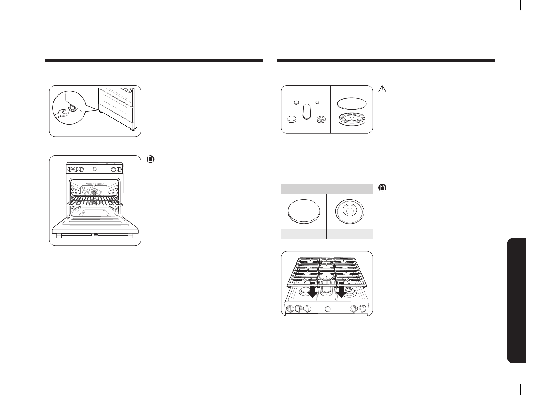
Step 12. Assemble the surface burners
CAUTION
Do not operate the surface burners without
all burner parts in place.
1. Position surface burner heads on top of
the surface burner manifolds as shown
at right. The electrodes will t into the
slot in the bottom of the heads.
Make sure the surface burner heads are
at and parallel with the cooktop.
2. Place the matching size caps on top of
each surface burner head.
Precise Simmer Burner (RR)
Flat surface Concave line
NOTE
The caps on Precise simmer burner
(RR) and inside Dual Burner (RF) can be
interchangeably used.
3. Place the left, center, and right surface
burner grates on the cooktop.
The edges of the grates should match
up with the edges of the cooktop.
Step 11. Level the range
Leveling leg
1. Make sure the range is positioned
where you want it.
2. Using a wrench, level the range by
turning the front leveling legs in or
out as necessary. Counterclockwise
shortens the leg and lowers the range.
Clockwise lengthens the leg and raises
the range.
NOTE
• Adjusting the two front legs is usually
sufcient, but adjust all four legs if
necessary.
• Adjust the leveling legs only as far as
necessary to level the range. Extending
the leveling legs more than necessary
or removing legs can cause the range
to be unstable.
3. If range is next to or between cabinets,
make sure the cooktop (without the
surface burner grates) is level with the
countertops.
4. Position an oven rack in the center rack
position.
5. Check the level of the range with a
carpenter level using the two positions
shown at right.
6. After the range becomes level, slide the
range away from the wall so that the
anti-tip bracket can be installed.
DG68-01650A-02_IM_NSY6DG8550SRAA_EN+MES+CFR.indb 25DG68-01650A-02_IM_NSY6DG8550SRAA_EN+MES+CFR.indb 25 2024-12-03 오후 4:13:312024-12-03 오후 4:13:31

26 English
Installation instructions
Installation instructions
Checking the ame quality:
All combustion ames need to be visually checked to determine their ame
quality.
2
3
1
1. Soft blue ames—Normal for natural
gas operation.
2. Yellow tips on outer cones—Normal for
LP gas operation.
3. Yellow ames—Abnormal for any gas
operation; call for service.
NOTE
If burner ame looks like 3, the range
should not be used until it is serviced.
Call for service. Normal burner ames shall
look like 1 or 2, depending on the gas type
you use.
Step 13. Check the ignition of surface burners
Check the operation of all cooktop and oven burners after the range has been
installed and assembled, gas supply lines have been carefully checked for leaks,
and electrical power cord has been plugged in.
All surface and oven burners have electronic ignition.
3
2
1
1
To turn on a surface burner:
1. Press the button integrated into the
knob.
2. Push in and turn the control knob for
that surface burner to the Lite position.
The "clicking" sound indicates the
electronic ignition system is operating
properly.
The burner will light in about 4 seconds,
after the air has been purged from the
supply line.
3. After the burner lights, turn the control
knob to the desired setting. The
"clicking" sound will stop and the ame
height will change from Max. to Min.
during turning the control knob.
4. Repeat steps 1, 2, 3 to check the
operation of each surface burner in
succession.
NOTE
Place food in the oven after preheating
if the recipe calls for it. Preheating is
important for good baking results.
After the oven has reached the desired
cooking temperature, it will beep.
DG68-01650A-02_IM_NSY6DG8550SRAA_EN+MES+CFR.indb 26DG68-01650A-02_IM_NSY6DG8550SRAA_EN+MES+CFR.indb 26 2024-12-03 오후 4:13:312024-12-03 오후 4:13:31
English 27
Installation instructions
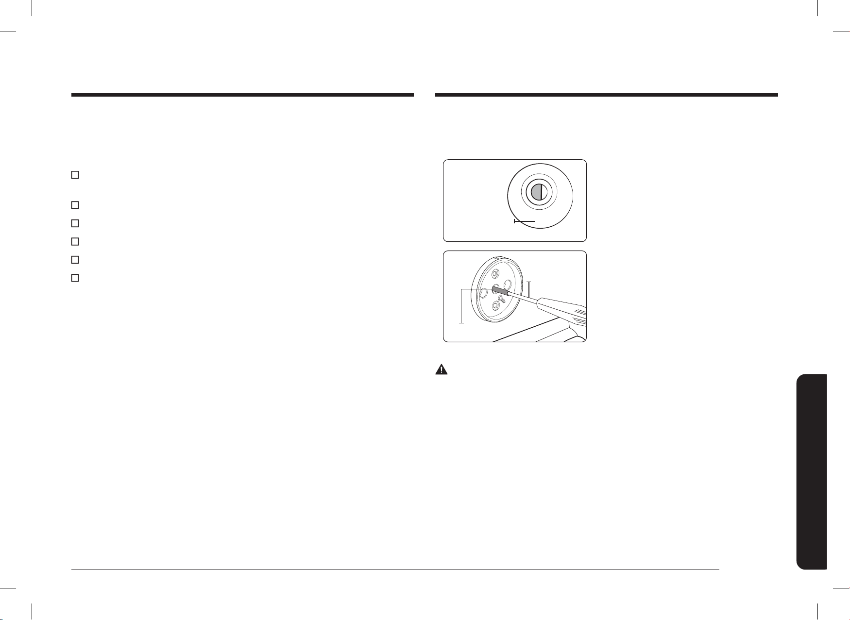
To adjust ame low setting
Identify which burner is exhibiting too high or too low of simmer rate via manifold
panel graphics.
Simmer Set
Screw
1. Rotate a knob to Lo position and
remove the knob from the valve stem
while the ame is lit.
Small
Screwdriver
Valve Stem
2. Carefully push the screw driver into
the stem of the valve, until it hits
the simmer set screw. Make sure the
screwdriver athead is seated into the
set screw groove.
3. Rotate valve set screw clockwise to
decrease Lo setting ame output, or
rotate set screw counter clockwise to
increase Lo setting ame output.
WARNING
1. Do not completely remove the valve set screw from the valve stem.
Do not loosen more than 3 turns of the valve set screw. The valve set screw is
an integral part of the gas valve assembly. Removing the valve set screw will
cause gas to leak.
2. After adjusting the valve set screw, inspect the assembly for gas leaks.
Step 14. Final installation checklist
You have just completed installing your range. Make sure all controls are in the off
position and the ow of ventilation air to the range is unobstructed. The following
is a checklist to conrm your range is safely installed and ready for operation.
Gas line has been properly connected to the range. The gas has been turned
on. All connections have been checked for leaks.
Range is plugged into the properly grounded electrical receptacle.
Approved anti-tip bracket is properly installed and engaged with the range.
Range is leveled and is rmly sitting on a solid, level oor.
Gas surface burners have been properly assembled.
All burners have been tested for proper operation.
DG68-01650A-02_IM_NSY6DG8550SRAA_EN+MES+CFR.indb 27DG68-01650A-02_IM_NSY6DG8550SRAA_EN+MES+CFR.indb 27 2024-12-03 오후 4:13:312024-12-03 오후 4:13:31
QUESTIONS OR COMMENTS?
COUNTRY CONTACT CENTER WEB SITE
U.S.A
Consumer Electronics
1-800-SAMSUNG (726-7864) www.samsung.com/us/support
CANADA 1-800-SAMSUNG(726-7864)
www.samsung.com/ca/support (English)
www.samsung.com/ca_fr/support (French)
DG68-01650A-02
Scan the QR code* or visit
www.samsung.com/spsn
to view our helpful
How-to Videos and Live Shows
* Requires reader to be installed on your
smartphone
Scan this with your smartphone
DG68-01650A-02_IM_NSY6DG8550SRAA_EN+MES+CFR.indb 28DG68-01650A-02_IM_NSY6DG8550SRAA_EN+MES+CFR.indb 28 2024-12-03 오후 4:13:312024-12-03 오후 4:13:31

Estufa Dual Fuel
Manual de instalación
NSY6
**
8
*
5
***
DG68-01650A-02_IM_NSY6DG8550SRAA_EN+MES+CFR.indb 1DG68-01650A-02_IM_NSY6DG8550SRAA_EN+MES+CFR.indb 1 2024-12-03 오후 4:13:322024-12-03 오후 4:13:32
2 Español
Contenido
Contenido
Antes de comenzar 3
Información de seguridad importante 4
Lea todas las instrucciones antes de usar este artefacto. 4
Símbolos usados en este manual 4
Advertencia de la Propuesta 65 de California 4
Mancomunidad de Massachusetts 4
Seguridad general 4
Seguridad contra incendios 5
Seguridad del gas 5
Seguridad eléctrica y de conexión a tierra 6
Seguridad de la instalación 6
Seguridad de la ubicación 7
Seguridad de la placa de cocción 7
Seguridad del horno 8
Seguridad del cajón de almacenamiento 9
Seguridad del horno autolimpiante 9
Componentes de la estufa Dual Fuel 10
Contenido de la caja 10
Requisitos de instalación 11
Requisitos de ubicación 11
Para evitar roturas 14
Requisitos de gas 15
Requisitos especiales para el gas (modelos a gas vendidos en Massachusetts) 15
Requisitos eléctricos 16
ADVERTENCIA
No seguir las instrucciones de este manual con exactitud puede
provocar un incendio o una explosión que podría ocasionar daños
materiales, lesiones o la muerte.
• NO guarde ni utilice gasolina u otros productos inamables cerca de este
artefacto.
• QUÉ HACER SI HAY OLOR A GAS:
- NO encienda ningún otro artefacto.
- NO toque ningún interruptor eléctrico.
- NO utilice ningún teléfono dentro del edicio.
- Llame inmediatamente al proveedor de gas desde el teléfono de un
vecino. Siga las instrucciones del proveedor de gas.
- Si no puede comunicarse con el proveedor de gas, llame al
departamento de bomberos.
• La instalación y el servicio técnico deben ser realizados por el proveedor
de gas, o un instalador o agencia de servicio técnico calicados.
Dispositivo antinclinación
ADVERTENCIA
TODAS LAS ESTUFAS PUEDEN INCLINARSE Y PROVOCAR LESIONES.
LA INCLINACIÓN DE LAS ESTUFAS PUEDE CAUSAR QUEMADURAS POR
DERRAMES, LESIONES O LA MUERTE.
INSTALE Y REVISE LA MÉNSULA ANTINCLINACIÓN SIGUIENDO LAS
INSTRUCCIONES Y LA PLANTILLA QUE VIENEN CON ELLA.
• Para evitar que la estufa se incline accidentalmente, je un dispositivo
antinclinación aprobado al piso (consulte la sección "Instalación de la ménsula
antinclinación" en las Instrucciones de instalación). Intente inclinar la estufa
hacia adelante con cuidado, para vericar que la instalación se haya realizado
correctamente. El dispositivo antinclinación debería sujetarla y evitar que se incline.
• Si la estufa se aleja de la pared por algún motivo, asegúrese de unir nuevamente el
dispositivo antinclinación una vez que la estufa haya vuelto a su lugar.
• Siga las instrucciones de instalación del Manual de instalación. No seguir las
instrucciones puede causar la muerte, lesiones graves y daños materiales.
• Para evitar que la estufa se incline accidentalmente, NO se pare, se siente ni se
apoye en la puerta o el cajón.
• Asegúrese de que un técnico calicado haya instalado y conectado a tierra el
artefacto correctamente.
DG68-01650A-02_IM_NSY6DG8550SRAA_EN+MES+CFR.indb 2DG68-01650A-02_IM_NSY6DG8550SRAA_EN+MES+CFR.indb 2 2024-12-03 오후 4:13:322024-12-03 오후 4:13:32
Español 3
Antes de comenzar
Instrucciones de instalación 17
Instalación de la estufa Dual Fuel 17
Paso 1. Desembale la estufa. 17
Paso 2. Cumplir los requisitos de conexión eléctrica 17
Paso 3. Acceder a la conexión del cable de alimentación 18
Paso 4. Instalar el cable de alimentación 19
Paso 5. Instalar el conducto 20
Paso 6. Reemplazar la cubierta de acceso 22
Paso 7. Conectar la estufa al suministro de gas 22
Paso 8. Convertir a gas LP (opcional) 23
Paso 9. Instalar la ménsula antinclinación 24
Paso 10. Enchufar y colocar 24
Paso 11. Nivelar la estufa 25
Paso 12. Arme los quemadores superciales 25
Paso 13. Compruebe el encendido de los quemadores superciales. 26
Paso 14. Lista de vericación nal de la instalación 27
ACERCA DE ESTE MANUAL
LEA ESTAS INSTRUCCIONES EN SU TOTALIDAD Y CUIDADOSAMENTE.
NOTA IMPORTANTE PARA EL INSTALADOR
• Lea todas las instrucciones de este instructivo antes de proceder con la instalación de
la estufa.
• Quite todos los materiales de empaquetado de los compartimientos del horno antes de
conectar el suministro eléctrico y de gas a la estufa.
• Cumpla con todos los códigos y las ordenanzas vigentes.
• Asegúrese de dejar estas instrucciones al usuario.
• La instalación de este artefacto requiere habilidades mecánicas básicas.
• El instalador es responsable de llevar a cabo una instalación adecuada.
• La falla del producto debido a la instalación incorrecta no está cubierta por la garantía.
NOTA IMPORTANTE PARA EL USUARIO
Conserve estas instrucciones con el manual del usuario para futura referencia.
• Como cualquier artefacto que genera calor con su uso, debe seguir ciertas
precauciones de seguridad.
• Asegúrese de que un instalador o técnico de servicio calicado haya instalado y
conectado a tierra su estufa correctamente.
• Asegúrese de que los revestimientos de las paredes alrededor de la estufa puedan
soportar el calor que genera.
• Debe haber un espacio entre los muebles de almacenamiento y los quemadores
superciales de, al menos, 30 pulgadas (76,2 cm).
NOTA IMPORTANTE PARA EL TÉCNICO
El diagrama eléctrico se encuentra en un sobre en la parte trasera de la estufa.
Antes de comenzar
DG68-01650A-02_IM_NSY6DG8550SRAA_EN+MES+CFR.indb 3DG68-01650A-02_IM_NSY6DG8550SRAA_EN+MES+CFR.indb 3 2024-12-03 오후 4:13:322024-12-03 오후 4:13:32
4 Español
Información de seguridad importante
Información de seguridad importanteInformación de seguridad importante
LEA TODAS LAS INSTRUCCIONES ANTES DE USAR ESTE
ARTEFACTO.
• Todos los equipos de gas y eléctricos con piezas móviles pueden ser peligrosos.
Lea las instrucciones de seguridad importantes para el artefacto en este manual. Se
deben seguir las instrucciones para minimizar el riesgo de lesiones, muerte o daños
materiales.
• Guarde este manual. No lo tire.
SÍMBOLOS USADOS EN ESTE MANUAL
ADVERTENCIA
Peligros o prácticas poco seguras que pueden provocar lesiones personales graves o la
muerte.
PRECAUCIÓN
Peligros o prácticas poco seguras que pueden provocar descargas eléctricas, lesiones
personales o daños a la propiedad.
NOTA
Instrucciones y sugerencias útiles.
Los siguientes íconos y símbolos de advertencia son para evitar que usted y otras personas
sufran daños. Sígalos de forma explícita. Cuando haya leído esta sección, guárdela en un
lugar seguro para futuras consultas.
ADVERTENCIA DE LA PROPUESTA 65 DE CALIFORNIA
ADVERTENCIA
Cáncer y daño reproductivo: www.P65Warnings.ca.gov
MANCOMUNIDAD DE MASSACHUSETTS
Quien instale este producto debe ser un plomero autorizado o un gasista calicado o
autorizado del estado de Massachusetts. Cuando se utilicen válvulas de bola para el cierre
del gas, se debe usar una manija en forma de “T”. No se deben conectar varios conductos
exibles de gas en serie.
SEGURIDAD GENERAL
ADVERTENCIA
Para reducir el riesgo de incendio, descargas eléctricas, lesiones y muerte, respete estas
precauciones.
• No toque ninguna pieza de la estufa,
incluidos los quemadores del horno,
los quemadores superciales y las
supercies interiores mientras cocina o
inmediatamente después de haberlo hecho.
• Conozca la ubicación de la válvula de cierre
de gas y sepa cómo cerrarla.
• Asegúrese de que el dispositivo antinclinación esté bien instalado en la estufa.
Consulte las instrucciones de instalación para obtener más información.
• No permita que los niños se acerquen ni se suban a la estufa, ni que se metan dentro
de ella. No les permita jugar con la estufa ni con ninguna de sus piezas. Tampoco
deje a los niños sin supervisión en un área donde se esté usando la estufa. Para la
seguridad de los niños, se recomienda usar la función de traba de controles y puerta.
• Retire todos los materiales de embalaje del dispositivo para evitar la ignición.
Mantenga todos los materiales de embalaje fuera del alcance de los niños. Deseche los
materiales de embalaje de forma adecuada después de desembalar la estufa.
• No guarde objetos que les puedan resultar interesantes a los niños sobre la placa de
cocción ni en el protector trasero de la estufa. Si los niños treparan a la estufa para
alcanzar estos objetos, esto podría dar lugar a heridas graves o la muerte.
• No opere la estufa si tiene alguna parte dañada, funciona mal o le faltan piezas.
• No utilice la estufa como calentador de ambiente. Debe usarse solo para cocinar.
• No utilice limpiadores o cubiertas para horno dentro de este ni alrededor de alguna de
sus piezas.
DG68-01650A-02_IM_NSY6DG8550SRAA_EN+MES+CFR.indb 4DG68-01650A-02_IM_NSY6DG8550SRAA_EN+MES+CFR.indb 4 2024-12-03 오후 4:13:332024-12-03 오후 4:13:33
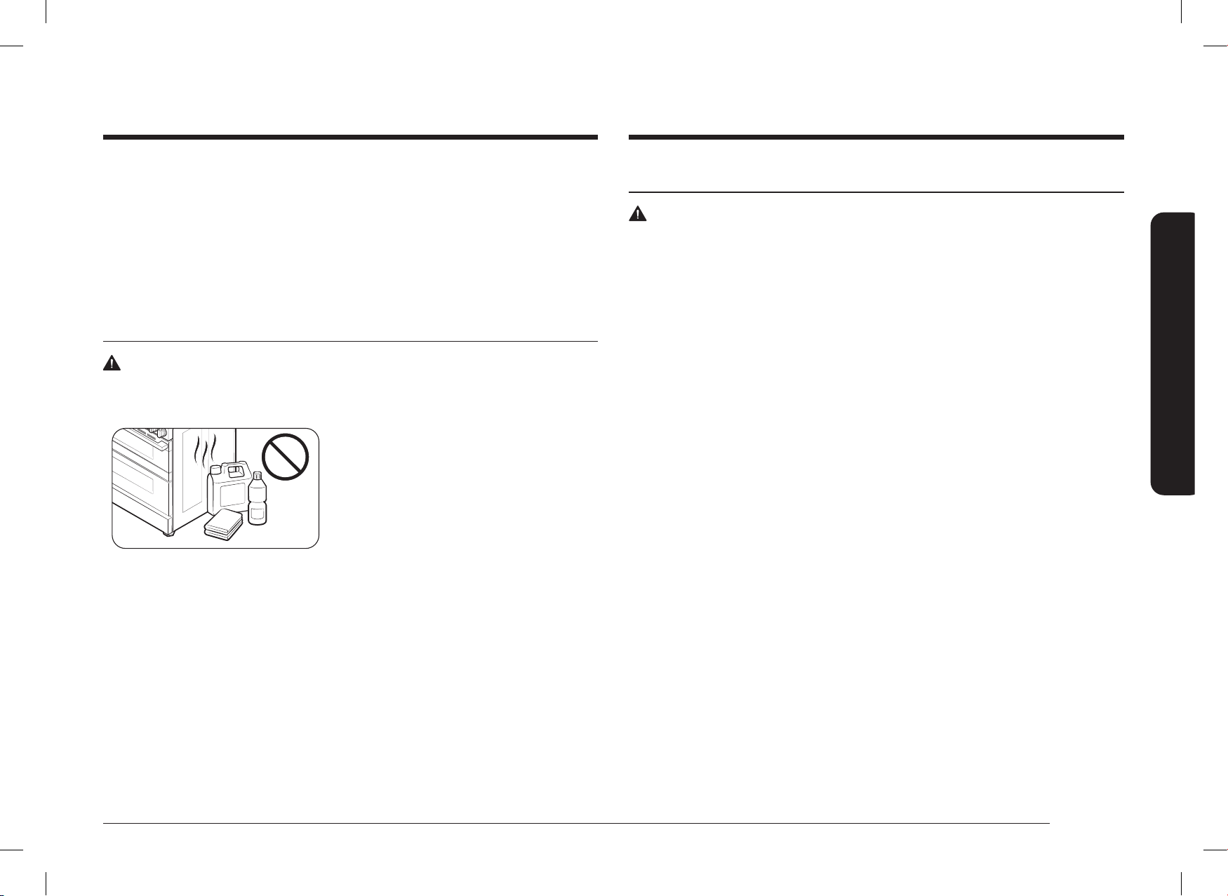
Español 5
Información de seguridad importante
SEGURIDAD DEL GAS
ADVERTENCIA
Para reducir el riesgo de incendio, descargas eléctricas, lesiones y muerte, respete estas
precauciones.
Si hay olor a gas:
• Cierre la válvula y no use la estufa.
• No prenda fósforos, velas o cigarrillos.
• No encienda artefactos a gas o eléctricos.
• No toque ningún interruptor eléctrico ni enchufe un cable de alimentación a un
tomacorriente.
• No utilice ningún teléfono dentro del edicio.
• Evacúe la habitación, el edicio o el área.
• Llame inmediatamente al proveedor de gas desde el teléfono de un vecino.
Siga las instrucciones del proveedor de gas.
• Si no puede comunicarse con el proveedor de gas, llame al departamento de
bomberos.
Vericación de pérdidas de gas
La prueba de pérdidas del artefacto debe realizarse de acuerdo con las instrucciones del
fabricante. No utilice una llama para vericar si hay pérdidas de gas. Utilice un cepillo para
esparcir una solución de agua jabonosa alrededor del área en cuestión. Si hay una pérdida
de gas, verá pequeñas burbujas en la solución jabonosa en el punto de fuga.
• Utilice únicamente agarradores aislantes secos.
• No utilice la estufa para calentar comida en envases cerrados.
• No golpee el vidrio del horno.
• Cuando se deshaga de la estufa, corte el cable de alimentación y quite la puerta.
• Desenchufe o desconecte la energía eléctrica antes de realizar el servicio técnico.
• Asegúrese de que toda la carne roja y de ave se cocine completamente. La carne roja
siempre se debe cocinar a una temperatura interna de 160 ºF (71 ºC). La carne de ave
siempre se debe cocinar a una temperatura interna de 180 ºF (82 ºC).
SEGURIDAD CONTRA INCENDIOS
ADVERTENCIA
Para reducir el riesgo de incendio, descargas eléctricas, lesiones y muerte, respete estas
precauciones.
• No guarde, coloque o use materiales
inamables o combustibles como carbón,
papel, plástico, agarradores aislantes,
revestimientos, cortinas, gasolina ni otros
líquidos o vapores inamables cerca de la
estufa ni dentro de ella.
• No use prendas amplias ni colgantes
mientras utiliza la estufa.
• Para evitar la acumulación de grasa, limpie regularmente las ventilaciones.
• No permita que los agarradores aislantes u otros materiales inamables toquen
un elemento caliente. No utilice una toalla ni otra tela voluminosa como agarrador
aislante.
• No utilice agua para apagar un incendio provocado por grasa. Para apagar un incendio
provocado por grasa, apague el quemador y extinga el incendio con una tapa bien
ajustada o use un extintor multipropósito de productos químicos secos o de espuma.
• Si ocurriera un incendio provocado por grasa en el horno, apáguelo presionando el
botón Apagado. Mantenga la puerta del horno cerrada hasta que se extinga el fuego.
Si fuera necesario, utilice un extintor multipropósito de productos químicos secos o de
espuma.
• No caliente comida en recipientes cerrados; la presión puede causar que el recipiente
estalle y provoque lesiones.
DG68-01650A-02_IM_NSY6DG8550SRAA_EN+MES+CFR.indb 5DG68-01650A-02_IM_NSY6DG8550SRAA_EN+MES+CFR.indb 5 2024-12-03 오후 4:13:332024-12-03 오후 4:13:33

6 Español
Información de seguridad importante
Información de seguridad importante
SEGURIDAD DE LA INSTALACIÓN
ADVERTENCIA
Para reducir el riesgo de incendio, descargas eléctricas, lesiones y muerte, respete estas
precauciones.
• Un instalador calicado debe instalar y
conectar a tierra correctamente su estufa,
según las instrucciones de instalación.
Los ajustes y el servicio técnico los debe
realizar únicamente un instalador de estufas
a gas o técnico de servicio calicado.
• No intente reparar, modicar ni reemplazar la estufa o alguna de sus piezas, excepto
que se recomiende especícamente en este manual. Todos los otros servicios técnicos
los debe realizar un técnico de servicio calicado.
• Siempre utilice conectores exibles nuevos para instalar un artefacto a gas.
No utilice conectores exibles viejos.
• Asegúrese de que el dispositivo antinclinación esté bien instalado en la estufa.
Consulte las instrucciones de instalación para obtener más información.
• Debido al tamaño y peso de la estufa, necesita dos personas o más para moverla.
• Retire toda la cinta y el empaquetado.
• Retire todos los accesorios de la placa de cocción, el horno y/o el cajón inferior. Las
rejillas y los comales son pesados. Tenga cuidado al manipularlas.
• Asegúrese de que no se suelten piezas durante el transporte.
• Asegúrese de que un técnico de servicio o instalador calicado para el tipo de
gas (natural o LP) que utilizará haya instalado y ajustado correctamente su estufa.
Para que su estufa utilice gas LP, el instalador debe sustituir los 5 oricios de los
quemadores superciales y los 2 oricios del horno por el juego de oricios LP
suministrado, e invertir el adaptador GPR. Estos ajustes los debe realizar un técnico
de servicio calicado conforme a las instrucciones del fabricante y todos los códigos
y requisitos de la autoridad competente. La agencia calicada que realice este trabajo
asume la responsabilidad por la conversión del gas.
SEGURIDAD ELÉCTRICA Y DE CONEXIÓN A TIERRA
ADVERTENCIA
Para reducir el riesgo de incendio, descargas eléctricas, lesiones y muerte, respete estas
precauciones.
• Enchufe el artefacto a un tomacorriente de
conexión a tierra de tres clavijas.
• No retire la clavija de conexión a tierra.
• No utilice un adaptador ni un alargue.
• No utilice un enchufe ni cable de
alimentación dañados ni un tomacorriente
ojo.
• No modique el enchufe, el cable de alimentación ni el tomacorriente.
• No coloque un fusible en el circuito neutral o de conexión a tierra.
• Utilice un circuito eléctrico dedicado de CA, 240 voltios, 60 Hz y 40 amperes equipado
con fusibles para esta estufa. Se recomienda un fusible de retardo o un disyuntor. No
enchufe más de un artefacto en este circuito.
• No conecte el cable a tierra a cañerías de tuberías de plástico, de gas o de agua
caliente.
• Esta estufa debe estar conectada a tierra. En caso de que funcione mal o se averíe,
la conexión a tierra reduce el riesgo de descarga eléctrica al proporcionar una vía de
escape para la corriente eléctrica. Esta estufa está equipada con un cable que tiene
un enchufe de conexión a tierra. El enchufe debe estar conectado rmemente a un
tomacorriente bien instalado y conectado a tierra según los códigos y ordenanzas
locales. Si no está seguro de que el tomacorriente esté conectado correctamente a
tierra, un electricista matriculado debe vericarlo.
• El servicio eléctrico de la estufa debe ajustarse a los códigos locales. A excepción de
los códigos locales, debe cumplir con la versión más reciente de ANSI/NFPA Nro. 70
(para los EE. UU.) o con el Código Eléctrico de Canadá CSA C22.1 o su versión más
reciente.
• Es responsabilidad personal del propietario de la estufa proporcionar el servicio
eléctrico correcto.
DG68-01650A-02_IM_NSY6DG8550SRAA_EN+MES+CFR.indb 6DG68-01650A-02_IM_NSY6DG8550SRAA_EN+MES+CFR.indb 6 2024-12-03 오후 4:13:332024-12-03 오후 4:13:33
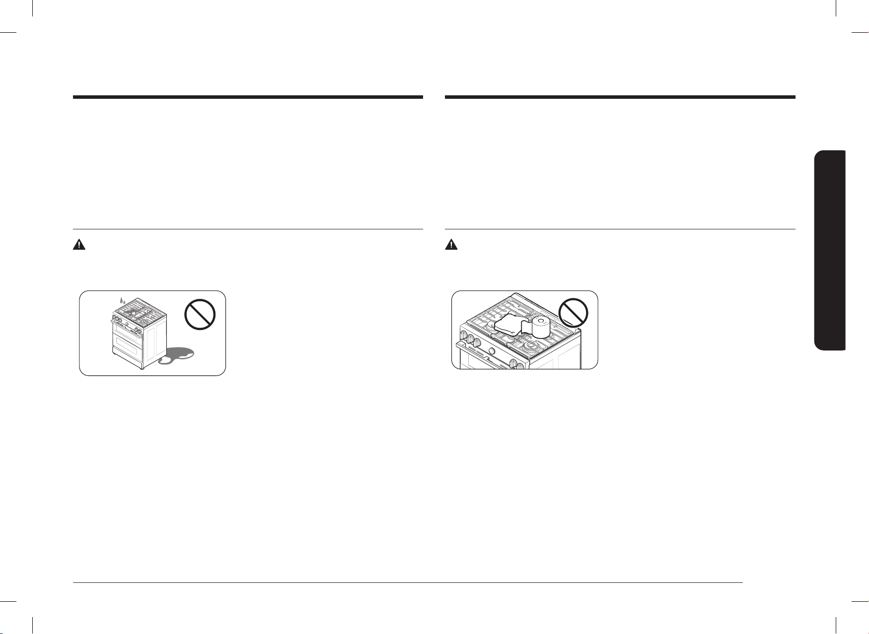
Español 7
Información de seguridad importante
• Asegúrese de que los revestimientos de las paredes alrededor de la estufa puedan
soportar un calor de hasta 194 °F (90 °C) generado por el artefacto.
• Evite colocar muebles de almacenamiento arriba de la supercie de la estufa.
Si necesita muebles de almacenamiento arriba de la estufa, deje una distancia mínima
de 30 pulgadas (76.2 cm) entre la supercie de cocción y la base de los muebles, o
instale una campana extractora que cubra horizontalmente un mínimo de 5 pulgadas
(12.7 cm) la base de los muebles.
SEGURIDAD DE LA PLACA DE COCCIÓN
ADVERTENCIA
Para reducir el riesgo de incendio, descargas eléctricas, lesiones y muerte, respete estas
precauciones.
• Asegúrese de apagar todos los quemadores
cuando no estén en uso.
• No utilice papel de aluminio para cubrir
las rejillas ni ninguna parte de la placa de
cocción.
• No deje los quemadores sin supervisión en
entornos con niveles de calor medios o altos.
• Antes de encender los quemadores, asegúrese de que todas las tapas estén
correctamente instaladas en su lugar y niveladas.
• Utilice siempre la posición LITE (Encender) para encender los quemadores y asegúrese
de que enciendan. Si falla el encendido, gire la perilla a Apagado y espere hasta que se
disipe el gas.
• Cuando coloque un quemador a fuego lento, no gire la perilla rápidamente. Asegúrese
de que la llama siga viva.
• No ponga objetos que no sean utensilios de cocina sobre la placa de cocción.
• La placa de cocción está diseñada para cocinar con un wok o un anillo para wok.
Si se ambean alimentos, solo debe hacerse debajo de una campana de ventilación
encendida.
• Antes de retirar o cambiar los utensilios de cocina, apague los quemadores.
• Quite la comida y los utensilios de cocina inmediatamente después de cocinar.
• La instalación de esta estufa debe realizarse conforme a los códigos locales o, en su
ausencia, a la última edición del Código Nacional de Gas de Combustión, ANSI Z223.1/
NFPA.54. En Canadá, la instalación debe realizarse conforme al Código Nacional de
Gas de Combustión actual, CAN/CGA-B149.1, o el Código de Instalación de Propano
actual, CAN/CGA-B149.2, y a los códigos locales que correspondan. Esta estufa se
diseñó con certicación de ETL, de acuerdo con ANSI Z21.1, última edición, y la
Asociación Canadiense de Gas de acuerdo con CAN/CGA-1.1, última edición.
SEGURIDAD DE LA UBICACIÓN
ADVERTENCIA
Para reducir el riesgo de incendio, descargas eléctricas, lesiones y muerte, respete estas
precauciones.
• Esta estufa es solo para uso interior
y doméstico. No instale la estufa en
áreas expuestas al agua o a condiciones
meteorológicas adversas.
• No instale la estufa en un sitio expuesto a
una corriente de aire fuerte.
• Elija un piso nivelado y bien construido que pueda aguantar el peso de la estufa.
El piso sintético, como el linóleo, debe aguantar temperaturas de 180 °F (82 °C) sin
achicarse, deformarse o decolorarse. No instale la estufa directamente sobre alfombras
de cocina, excepto que coloque una lámina de madera contrachapada de ¼ de pulgada
o un aislante similar entre el artefacto y la alfombra.
• Elija una ubicación desde la cual se pueda acceder fácilmente al tomacorriente de
conexión a tierra de tres clavijas.
• Si coloca la estufa cerca de una ventana, no cuelgue cortinas o persianas de papel
largas en esa ventana.
• Para que la estufa se ventile correctamente, asegúrese de que las ventilaciones
no estén bloqueadas ni cubiertas y que haya distancia suciente arriba, atrás,
en los costados y debajo de la estufa. Las ventilaciones permiten la salida de
aire necesaria para que la estufa funcione adecuadamente con la combustión
correcta y se obtengan buenos resultados de cocción.
DG68-01650A-02_IM_NSY6DG8550SRAA_EN+MES+CFR.indb 7DG68-01650A-02_IM_NSY6DG8550SRAA_EN+MES+CFR.indb 7 2024-12-03 오후 4:13:332024-12-03 오후 4:13:33

8 Español
Información de seguridad importante
Información de seguridad importante
SEGURIDAD DEL HORNO
ADVERTENCIA
Para reducir el riesgo de incendio, descargas eléctricas, lesiones y muerte, respete estas
precauciones.
• No utilice el horno para nes que no sean
de cocina, como secar ropa o almacenar
objetos. Utilice el horno solo para cocinar.
• Asegúrese de que la parte interior de
la rejilla divisoria del horno esté en la
posición correcta dentro de la rejilla más
grande.
• Asegúrese de que las parrillas del horno se encuentren al mismo nivel en cada lado.
• No dañe, mueva ni limpie la junta de la puerta.
• No rocíe agua sobre el vidrio del horno mientras este se encuentre encendido ni
inmediatamente después de apagarlo.
• No utilice papel o cubiertas de aluminio en ninguna parte del horno. No utilice papel
aluminio ni otro material similar para cubrir oricios o pasajes en el fondo del horno o
para cubrir una rejilla.
• Aléjese del horno cuando abra la puerta.
• No deje que se acumule grasa en el horno.
• Cuando reubique las parrillas del horno, asegúrese de que el horno esté
completamente frío.
• Solo use utensilios de cocina recomendados para hornos a gas.
• Para evitar dañar las perillas de control de los quemadores, siempre que hornee o ase
alimentos hágalo con la puerta del horno cerrada.
• Mantenga los conductos de ventilación del horno libres de obstrucciones. El conducto
de ventilación del horno se encuentra debajo de la caja de control. Esta área podría
calentarse al usar el horno. Nunca bloquee esta ventilación ni coloque plásticos u
objetos sensibles al calor sobre ella.
• Cuando cocine o ase bolsas en el horno, siga las instrucciones del fabricante.
• Antes de quitar cualquier pieza del quemador para limpiarlo, asegúrese de que la estufa
esté apagada y completamente fría.
• Después de limpiar el distribuidor del quemador y antes de volver a ensamblarlo,
asegúrese de que esté completamente seco.
• Asegúrese de que la marca de encendido en el distribuidor del quemador doble esté
colocada junto al electrodo al ensamblarlo.
• Consulte la guía de inicio para saber cómo instalar los quemadores.
• Compruebe la calidad de la llama después de instalar todos los quemadores. Consulte la
página 25.
• Para evitar un envenenamiento por monóxido de carbono, no vierta agua en la placa de
cocción mientras limpia.
• Elija utensilios de cocina diseñados para cocinar en la estufa superior. Utilice elementos
de cocina lo sucientemente grandes como para cubrir las rejillas del quemador.
Ajuste las llamas de los quemadores para que no sobrepasen la base de los utensilios de
cocina.
• Para evitar la decoloración o deformación de los utensilios y envenenamiento por
monóxido de carbono, no elija utensilios que sean sustancialmente más grandes que la
rejilla.
• Asegúrese de ubicar los mangos de los utensilios de cocina hacia un lado o hacia atrás
de la placa de cocción, pero nunca sobre los quemadores superciales.
• Manténgase lejos de la estufa al freír.
• Para freír, caliente el aceite despacio y supervise la operación. Cuando fría alimentos a
alta temperatura, supervise detenidamente el proceso de cocción. Si combina grasas y
aceites al freír, mézclelos antes de calentarlos.
• Utilice un termómetro de freidora siempre que sea posible. Esto evita sobrecalentar la
freidora más allá del punto de ahumado.
• Utilice una cantidad mínima de aceite cuando fría en una sartén poco profunda o en una
freidora. Evite cocinar alimentos congelados o con una cantidad excesiva de hielo.
• Antes de mover los utensilios de cocina llenos de aceite o grasa, asegúrese de que se
hayan enfriado por completo.
• Para evitar la ebullición eruptiva retrasada, deje reposar los líquidos calientes al menos
20 segundos después de que apague el quemador, de manera que la temperatura del
líquido se pueda estabilizar. En caso de quemaduras, siga las instrucciones de primeros
auxilios a continuación:
1) Sumerja la zona quemada en agua fría o tibia por al menos 10 minutos.
2) No aplique cremas, aceites ni lociones.
3) Cubra con un paño limpio y seco.
DG68-01650A-02_IM_NSY6DG8550SRAA_EN+MES+CFR.indb 8DG68-01650A-02_IM_NSY6DG8550SRAA_EN+MES+CFR.indb 8 2024-12-03 오후 4:13:332024-12-03 오후 4:13:33
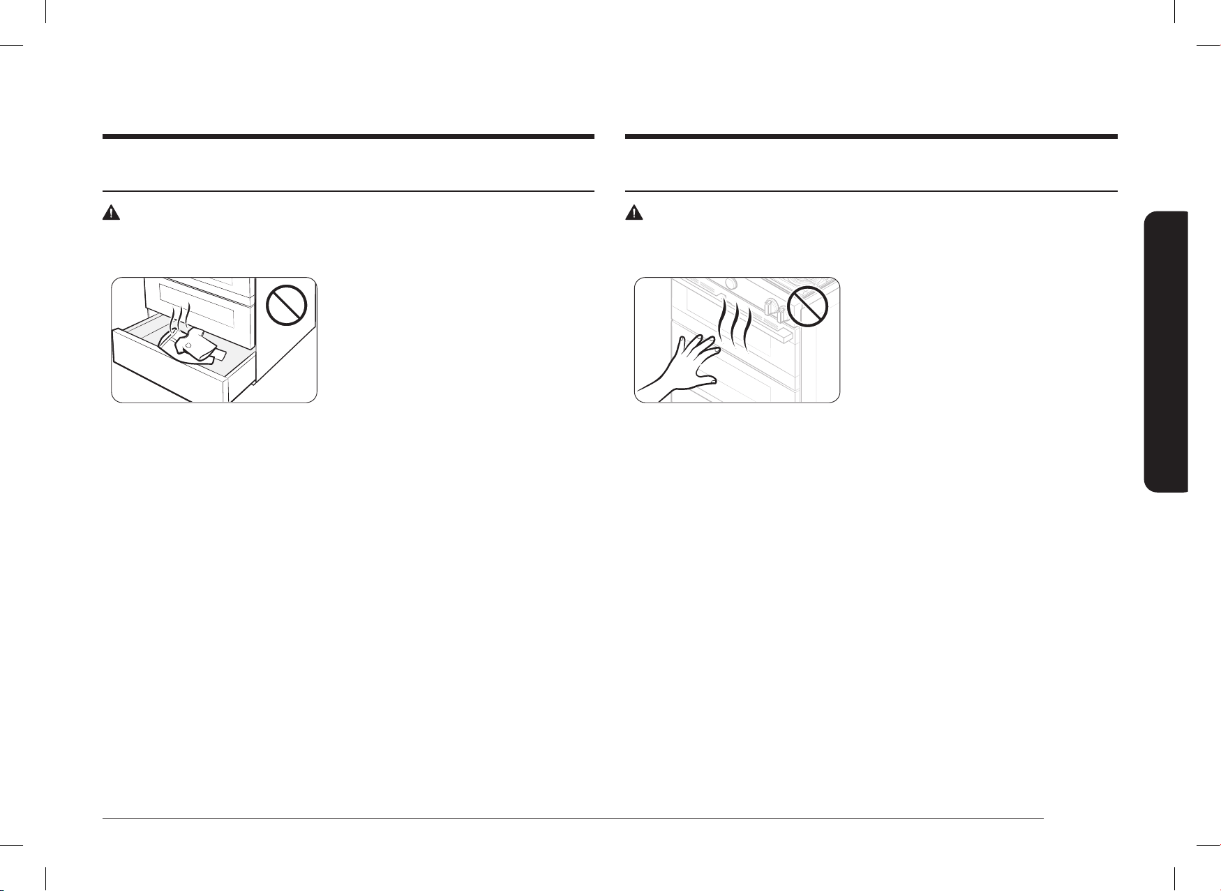
Español 9
Información de seguridad importante
SEGURIDAD DEL HORNO AUTOLIMPIANTE
ADVERTENCIA
Para reducir el riesgo de incendio, descargas eléctricas, lesiones y muerte, respete estas
precauciones.
• La función de autolimpieza opera el horno a
temperaturas lo sucientemente altas como
para quemar restos de comida dentro del
horno. La estufa estará extremadamente
caliente durante el ciclo de autolimpieza.
No toque ninguna supercie de la estufa
durante un ciclo de autolimpieza.
• Mantenga a los niños alejados del horno durante la totalidad del ciclo.
• Antes de comenzar el ciclo autolimpiante, quite todas las rejillas, los utensilios
de cocina y los utensilios del horno. Solo se pueden dejar rejillas recubiertas en
porcelana.
• Antes de comenzar el ciclo autolimpiante, quite la grasa y los restos de comida del
horno.
• No ponga el cajón inferior en la cavidad del horno cuando haga correr el ciclo
autolimpiante.
• Cuando abra la puerta después de un ciclo autolimpiante, manténgase alejado del
horno.
• Si el ciclo autolimpiante funciona mal, apague el horno, desconecte la alimentación de
energía y comuníquese con un técnico de servicio calicado.
SEGURIDAD DEL CAJÓN DE ALMACENAMIENTO
ADVERTENCIA
Para reducir el riesgo de incendio, descargas eléctricas, lesiones y muerte, respete estas
precauciones.
• No utilice el cajón para nes que no sean de
cocción, como secar ropa o guardar objetos.
Utilice el cajón solo para cocinar.
• No toque la supercie interior del cajón o
los elementos calientes.
• Para evitar quemaduras por el vapor, tenga
cuidado cuando abra el cajón.
• No utilice papel aluminio para revestir el
cajón.
• No coloque el cajón en el horno.
No coloque el cajón en el horno durante el
ciclo autolimpiante.
• No deje recipientes con grasa en el cajón ni
cerca de él.
DG68-01650A-02_IM_NSY6DG8550SRAA_EN+MES+CFR.indb 9DG68-01650A-02_IM_NSY6DG8550SRAA_EN+MES+CFR.indb 9 2024-12-03 오후 4:13:342024-12-03 오후 4:13:34
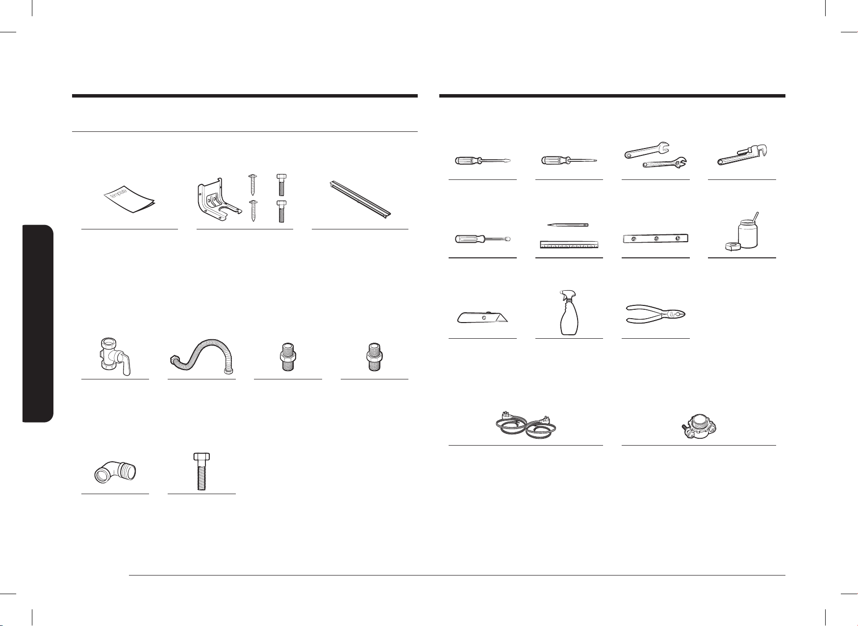
10 Español
Componentes de la estufa Dual Fuel
Contenido de la caja
Piezas suministradas
Plantilla Ménsula antinclinación (1) /
tornillos (4)
Kit de relleno (1) y
tornillos (2)
• Asegúrese de haber recibido todas las piezas suministradas que se indican arriba.
• Si su estufa se dañó durante el envío o si le falta alguna de las piezas, comuníquese
con su vendedor local.
Piezas necesarias
Válvula de cierre en la
tubería de gas
Conector exible
de metal del
electrodoméstico de
½ pulgada (diámetro
interior) x 5 pies
Adaptador de unión
cónica de ¾ pulgadas
o ½ pulgada (NPT)
x ½ pulgada
(diámetro interior)
Adaptador de unión
cónica de ½ pulgada
(NPT)
x ½ pulgada
(diámetro interior)
Codo de 135 grados
(opcional)
Tirafondo o anclaje
de manguito de
½ pulgada
(diámetro exterior)
Componentes de la estufa Dual Fuel
Herramientas necesarias
Destornillador de
punta plana
Destornillador Phillips Llave de boca ja o
ajustable
Llave Stillson (2)
Llave para tuercas de
¼ in
Lápiz y regla Nivel Compuesto de unión
de tuberías
Navaja multiuso Solución de agua
jabonosa
Pinzas
Lo que no se incluye
Cable de 3 o 4 conductores
(Aprobados por UL de 40 o 50 amperes)
* Solo para Canadá
Dispositivo de alivio de tensión
(Solo para la instalación del conducto)
DG68-01650A-02_IM_NSY6DG8550SRAA_EN+MES+CFR.indb 10DG68-01650A-02_IM_NSY6DG8550SRAA_EN+MES+CFR.indb 10 2024-12-03 오후 4:13:352024-12-03 오후 4:13:35

Español 11
Requisitos de instalación
36"
(914.4 mm) mín.
36
3
/4"
(933.5 mm) máx.
29
15
/16"
(761.0 mm)
26
7
/
16
"
(671.7 mm)
49
1
/
4
" (1250.3 mm)
Puerta totalmente
abierta
28
7
/
16
"
(721.8 mm)
con manija
Requisitos de ubicación
Distancias y dimensiones
ANTES DE COMENZAR a instalar este artefacto, consulte la siguiente información sobre
dimensiones y distancias. No ubique la estufa en un sitio en el que esté expuesta a
fuertes corrientes de aire. Deje una distancia adecuada entre la estufa y las supercies
combustibles adyacentes. Debe respetar estas distancias para hacer un uso seguro de la
estufa. La ubicación del tomacorriente y la tubería de gas pueden ajustarse para cumplir
con las siguientes dimensiones y distancias.
Para la instalación en Canadá, no debe instalarse una estufa independiente a menos de
4.7 pulgadas (12 cm) de cualquier supercie adyacente.
PRECAUCIÓN
La estufa está diseñada para cumplir con la temperatura máxima admisible para gabinetes
de madera de 194 ºF (90 ºC). Asegúrese de que los revestimientos de las paredes, las
mesadas y los gabinetes alrededor de la estufa puedan soportar el calor de hasta 194 °F
(90 °C) que genera la estufa. Si no lo soportan, puede ocurrir decoloración, delaminación o
derretimiento.
13" (33 cm)
Profundidad
del gabinete
superior
24"
(61 cm)
Profundidad
del gabinete
inferior
4"
(10.2 cm)
6"
(15.2 cm)
Distancia lateral
por encima de la
supercie de cocción
hasta la pared
36"
(91.4 cm)
30"
(76.2 cm)
18"
(45.7 cm)
30"
(76.2 cm)
0" (0 cm)
Distancia debajo
de la placa
cocción y en la
parte trasera y
laterales de la
estufa
Mínimo desde la
parte superior de
la placa de cocción
hasta los gabinetes
24.2"
(61.5 cm)
0"
(0 cm)
Requisitos de instalación
DG68-01650A-02_IM_NSY6DG8550SRAA_EN+MES+CFR.indb 11DG68-01650A-02_IM_NSY6DG8550SRAA_EN+MES+CFR.indb 11 2024-12-03 오후 4:13:352024-12-03 오후 4:13:35

12 Español
Requisitos de instalación
Requisitos de instalación
Excepción 2: Para la instalación en isla, mantenga un mínimo de 2 ½ in desde el borde
trasero hasta el borde posterior de la mesada y un mínimo de 4 in desde el borde trasero
hasta los bordes laterales de la mesada.
IMPORTANTE:
Para eliminar el riesgo de quemaduras o incendios al intentar alcanzar objetos sobre las
unidades de supercie calientes, evite que el espacio de almacenamiento del gabinete esté
situado por encima de las unidades de supercie. Si dispone de espacio de almacenamiento
en los gabinetes sobre los elementos de calentamiento, puede reducir el riesgo al instalar
una campana extractora que sobresalga horizontalmente por un mínimo de 5 pulgadas por
encima de la parte inferior de los gabinetes.
Guía de instalación
A
36" - 36
36" - 36
3
3
/
/
4
4
"
"
(914.4 mm -
(914.4 mm -
933.5 mm)
933.5 mm)
26
26
7
7
/
/
16
16
"
"
(671.7 mm)
(671.7 mm)
29
29
15
15
/
/
16
16
"
"
(761.0 mm)
(761.0 mm)
25"
25"
3"
3"
24"
24"
24"
24"
3"
3"
35
35
7
7
/
/
8
8
"
"
A: Abertura del gabinete 30 in (76.2 cm)
IMPORTANTE: Si su gabinete tiene una altura superior a 36
3
/4 in, esta estufa no puede
ser instalada sin una unidad de soporte como un bloque de hormigón.
PRECAUCIÓN
NO instale el horno de manera que la puerta quede a la altura del gabinete.
Para instalar sobre estufa de gas, siga el CÓDIGO DE GAS local.
Dimensiones mínimas
ADVERTENCIA
Si se proporcionan gabinetes superiores, también debe proporcionarse una campana
extractora que sobresalga horizontalmente un mínimo de 5 pulgadas (12.7 cm) más
allá de la parte frontal de los gabinetes. Esto disipará cualquier exceso de calor en los
gabinetes superiores y evitará la posibilidad de incendios, lesiones o muerte. La campana
de ventilación debe estar hecha de chapa metálica de un grosor no inferior a 0.0122 in.
Instálela encima de la placa de cocción con un espacio libre no inferior a ¼ in entre la
campana y la parte inferior del material combustible o del gabinete metálico. La campana
debe ser al menos tan ancha como la estufa y estar bien centrada por encima. La distancia
entre la supercie de cocción y la supercie de la campana de ventilación no debe ser
inferior a 24 pulgadas.
Excepción n.º 1: La instalación de un horno microondas o un artefacto de cocción sobre la
placa de cocción deberá ajustarse a las instalaciones suministradas con dicho artefacto.
• Se requiere una distancia mínima de 30 in (76.2 cm) entre la parte superior de
la supercie de cocción y la parte inferior de un gabinete de madera o metal sin
protección; o si no es posible una distancia de 30 in (76.2 cm), se puede utilizar un
mínimo de 24 in (61 cm) cuando la parte inferior del gabinete de madera o metal esté
protegida por no menos de 0.25 in (0.64 cm) de cartón fresado retardante de llama
cubierto con chapa de acero MSG no inferior al acero inoxidable n.º 28 de 0.015 in
(0.038 cm), aluminio de 0.024 in (0.061 cm) o cobre de 0.020 in (0.051 cm).
• Se requiere una distancia mínima de 18 in (45.7 cm) entre la mesada y la parte
inferior del gabinete adyacente.
DG68-01650A-02_IM_NSY6DG8550SRAA_EN+MES+CFR.indb 12DG68-01650A-02_IM_NSY6DG8550SRAA_EN+MES+CFR.indb 12 2024-12-03 오후 4:13:352024-12-03 오후 4:13:35

Español 13
Requisitos de instalación
Kit de relleno trasero opcional
ADVERTENCIA
Se usa para rellenar la brecha entre la parte posterior de la estufa y la pared. Se agrega
una banda de relleno a la parte trasera de la estufa. Este kit solo puede usarse cuando la
abertura de la mesada es de 25" de profundidad.
NOTA
Si la profundidad de la mesada es superior a 25", habrá una separación entre el kit de
relleno y la pared posterior.
Ubicaciones recomendadas para las tuberías de gas y los tomacorrientes
eléctricos (Para modelos NSY6
**
8
*
5
***
)
Zona recomendada
Zona recomendada
para el tomacorriente
para el tomacorriente
de 120V/240V o
de 120V/240V o
120V/208V en la
120V/208V en la
pared posterior
pared posterior
Posición
Posición
recomendada
recomendada
30" (76.2cm)
30" (76.2cm)
Abertura del
Abertura del
gabinete
gabinete
17" (43.2 cm)
17" (43.2 cm)
12"
12"
(30.5 cm)
(30.5 cm)
Área de la pared
Área de la pared
para gas
para gas
Zona recomendada para la conexión
Zona recomendada para la conexión
a través de la pared y a través del
a través de la pared y a través del
suelo de la derivación de la tubería
suelo de la derivación de la tubería
de gas y la válvula de cierre.
de gas y la válvula de cierre.
Área del suelo
Área del suelo
para gas
para gas
17"
17"
(43.2 cm)
(43.2 cm)
9"
9"
(22.9 cm)
(22.9 cm)
2"
2"
(5.1 cm)
(5.1 cm)
PRECAUCIÓN
Debe utilizar el kit de relleno trasero para instalar la estufa en un gabinete independiente.
Para obtener más información, consulte la sección “Kit de relleno trasero opcional” como se
muestra a continuación.
DG68-01650A-02_IM_NSY6DG8550SRAA_EN+MES+CFR.indb 13DG68-01650A-02_IM_NSY6DG8550SRAA_EN+MES+CFR.indb 13 2024-12-03 오후 4:13:362024-12-03 오후 4:13:36
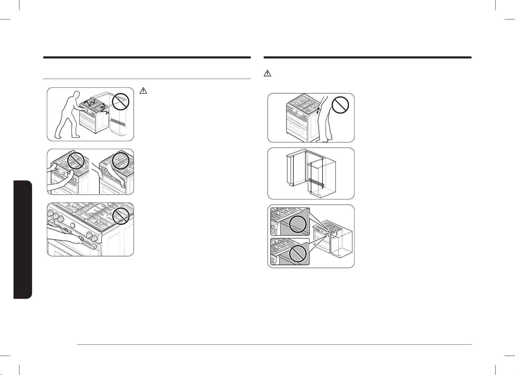
14 Español
Requisitos de instalación
Requisitos de instalación
PRECAUCIÓN
NO levante ni manipule la unidad por el marco de la placa de cocción.
Fig. 1
Fig. 1
1. La mesada alrededor del borde debe
estar plana y nivelada (consulte la zona
sombreada de la Fig. 1).
2. Antes de instalar la unidad, mida las alturas
de los dos laterales del gabinete (C1
~
C4),
frontal y posterior (consulte la Fig. 1)
desde el suelo hasta la parte superior de la
mesada.
3. Nivele la estufa utilizando las cuatro patas
niveladoras de modo que la altura desde
el suelo a la parte inferior del marco de la
placa de cocción sea mayor que la medida
del armario más alto en al menos 1/16 in.
4. Deslice la unidad en el gabinete (NO
EMPUJE FUERTEMENTE LA UNIDAD).
Asegúrese de que el centro de la unidad
esté alineado con el centro del borde del
gabinete.
5. El reborde metálico situado debajo de cada
lado de la placa de cocción DEBE colocarse
sobre la mesada del gabinete para que
la unidad quede bien sujeta. La placa de
cocción NO debe apoyarse directamente
sobre la mesada, de lo contrario podría
causar daños en la misma, lo que anularía la
garantía. Si es necesario, nivele la unidad.
Para evitar roturas
PRECAUCIÓN
NO empuje fuertemente la unidad cuando la
instale. Esto podría dañarla.
NO presione las perillas de los quemadores
cuando instale la estufa.
(Sujete ambos lados de la puerta [izquierdo y
derecho] para empujar la unidad).
No sujete ni presione la manija cuando realice la
instalación.
DG68-01650A-02_IM_NSY6DG8550SRAA_EN+MES+CFR.indb 14DG68-01650A-02_IM_NSY6DG8550SRAA_EN+MES+CFR.indb 14 2024-12-03 오후 4:13:362024-12-03 오후 4:13:36
Español 15
Requisitos de instalación
Requisitos especiales para el gas (modelos a gas vendidos en
Massachusetts)
REQUISITOS DE LA MANCOMUNIDAD DE MASSACHUSETTS:
ADVERTENCIA
• Pueden producirse pérdidas de gas en su sistema, lo que generaría una situación
peligrosa.
- No siempre se pueden detectar las pérdidas de gas solo por el olor.
- Los proveedores de gas recomiendan comprar e instalar un detector de gas
aprobado por UL. El detector de gas debe ser instalado únicamente de acuerdo
con las instrucciones del fabricante.
• La estufa debe ser instalada por un plomero con licencia o un gasista matriculado por
el estado de Massachusetts.
• Se DEBE instalar una válvula de gas manual con manija en forma de "T" en el conducto
de suministro de gas de la estufa.
• Si se usa un conector exible de gas para instalar la estufa, no se deben conectar
varios conductos exibles de gas en serie.
Requisitos de gas
Proporcione suministro de gas adecuado.
Esta estufa está diseñada para funcionar a una presión de 5 in (13 cm) de columna de agua
con gas natural o 10 in (25 cm) de columna de agua con gas LP (propano o butano).
Asegúrese de suministrar a su estufa el tipo de gas para el que se diseñó.
No intente convertir el artefacto del gas especicado en este manual a un gas diferente sin
consultar al proveedor de gas.
Esta estufa es convertible: puede usarse con gas natural o propano. Si decide usar la estufa
con gas LP, un instalador de gas LP calicado debe realizar la conversión antes de intentar
usar la estufa.
Para un funcionamiento correcto, la presión del gas natural suministrado al regulador debe
estar entre 5 in y 13 in (13 cm y 33 cm) de columna de agua.
Para el gas LP, la presión suministrada debe estar entre 10 in y 13 in (25 cm y 33 cm) de
columna de agua.
Al vericar el funcionamiento correcto del regulador, la presión de entrada debe ser al
menos 1 in (2.5 cm) mayor que la presión de funcionamiento (colector) determinada.
El regulador de presión ubicado en la entrada del colector de la estufa debe permanecer en
la tubería de suministro, independientemente de si se usa gas natural o LP.
El conector metálico exible utilizado para conectar la estufa a la línea de suministro de
gas debe tener un diámetro interior de 0.5 in (1.3 cm) y una longitud de 5 pies (152 cm)
para facilitar la instalación. En Canadá, los conectores exibles deben ser conectores
metálicos de pared simple de 6 pies (183 cm) de longitud como máximo.
No retuerza ni dañe el tubo metálico exible al desplazar la estufa.
DG68-01650A-02_IM_NSY6DG8550SRAA_EN+MES+CFR.indb 15DG68-01650A-02_IM_NSY6DG8550SRAA_EN+MES+CFR.indb 15 2024-12-03 오후 4:13:372024-12-03 오후 4:13:37
16 Español
Requisitos de instalación
Requisitos de instalación
Conexión a tierra
• Todas las estufas deben estar conectadas a tierra por seguridad personal.
• Todos los modelos a gas están equipados con un cable de alimentación que dispone de
un conductor de conexión a tierra para el equipo y un enchufe de conexión a tierra.
• No utilice un enchufe dañado ni un tomacorriente de pared ojo.
• No utilice un alargue ni un enchufe adaptador con este artefacto.
• Bajo ninguna circunstancia corte, modique, quite o anule la clavija a tierra (tercera
clavija) del cable de alimentación. Si el enchufe y el tomacorriente no coinciden o
tiene alguna duda, solicite a un electricista calicado que instale un tomacorriente
adecuado.
El cliente debe hacer que un electricista calicado revise el tomacorriente de pared y
el circuito para asegurarse de que el tomacorriente esté conectado a tierra de manera
correcta.
No se requieren ni se recomiendan interruptores de circuito por falla a tierra (GFCI)
para los receptáculos de gas de la estufa.
• NUNCA conecte un cable de conexión a tierra a cañerías de plomería de plástico,
tuberías de gas o de agua.
PRECAUCIÓN
El hecho de no seguir estas instrucciones puede ser causa de muertes, incendios o fallas
eléctricas.
Requisitos adicionales de instalación para casas rodantes
La instalación de los electrodomésticos diseñados para casas rodantes debe cumplir con
la Norma de Construcción y Seguridad de Casas Prefabricadas, Título 24 CFR, Parte 3280
(denominada anteriormente Norma Federal para la Construcción y la Seguridad de Casas
Rodantes, Título 24, HUD, Parte 280) o, cuando no corresponda su aplicación, la versión
más reciente de la Norma para Instalaciones en Casas Prefabricadas (lugares para casas
prefabricadas, comunidades y armados), la versión más reciente de ANSI A225.1, o los
códigos locales. En Canadá, la instalación de casas rodantes debe cumplir con el Código de
Instalación de Casas Rodantes CAN/CSA Z240/MH actual.
Requisitos eléctricos
ADVERTENCIA
Para reducir el riesgo de incendios, descargas eléctricas o lesiones, respete estas
precauciones:
Todas las estufas
• No utilice un alargue ni un enchufe adaptador con esta estufa.
• Esta estufa debe estar correctamente conectada a tierra.
• Consulte a un electricista calicado si no está seguro de si su estufa está
correctamente conectada a tierra.
• No modique el enchufe suministrado con su estufa; si no encaja en el tomacorriente,
solicite a un electricista calicado que instale uno adecuado.
• Todo el cableado y la conexión a tierra deben cumplir con los códigos locales o, en su
ausencia, con la versión más reciente del Código Eléctrico Nacional ANSI/NFPA n.º 70
(EE. UU.) o las versiones más recientes del Código Eléctrico de Canadá CSA C22.1 y los
códigos y ordenanzas locales.
• El diagrama de cableado se encuentra en la parte trasera de la estufa. (Dentro del
cable posterior de la cubierta)
• Esta estufa está equipada con un sistema de encendido electrónico que no funcionará
si se conecta a un tomacorriente que no esté correctamente polarizado.
Modelos a gas
• Los modelos a gas de Canadá están equipados con un cable de alimentación que
dispone de un conductor de conexión a tierra para el equipo y un enchufe de conexión
a tierra. (en el modelo de EE. UU. no se incluye el cable de alimentación).
• Se requiere un servicio eléctrico aprobado de 240 voltios, 60 Hz, CA, con disyuntor
de 40 amperios o fusible de retardo para todos los modelos estadounidenses y
canadienses.
• Compruebe que haya un alivio de tensión con certicación UL de ¾" (1.9 cm) donde el
cable de alimentación sale del gabinete de la estufa.
• No reutilice un cable de alimentación de una estufa anterior u otro artefacto.
• El cableado de alimentación eléctrica debe retenerse en el gabinete de la estufa con
un aliviador de tensión UL adecuado.
• También se recomienda un fusible de retardo o un disyuntor.
DG68-01650A-02_IM_NSY6DG8550SRAA_EN+MES+CFR.indb 16DG68-01650A-02_IM_NSY6DG8550SRAA_EN+MES+CFR.indb 16 2024-12-03 오후 4:13:372024-12-03 오후 4:13:37
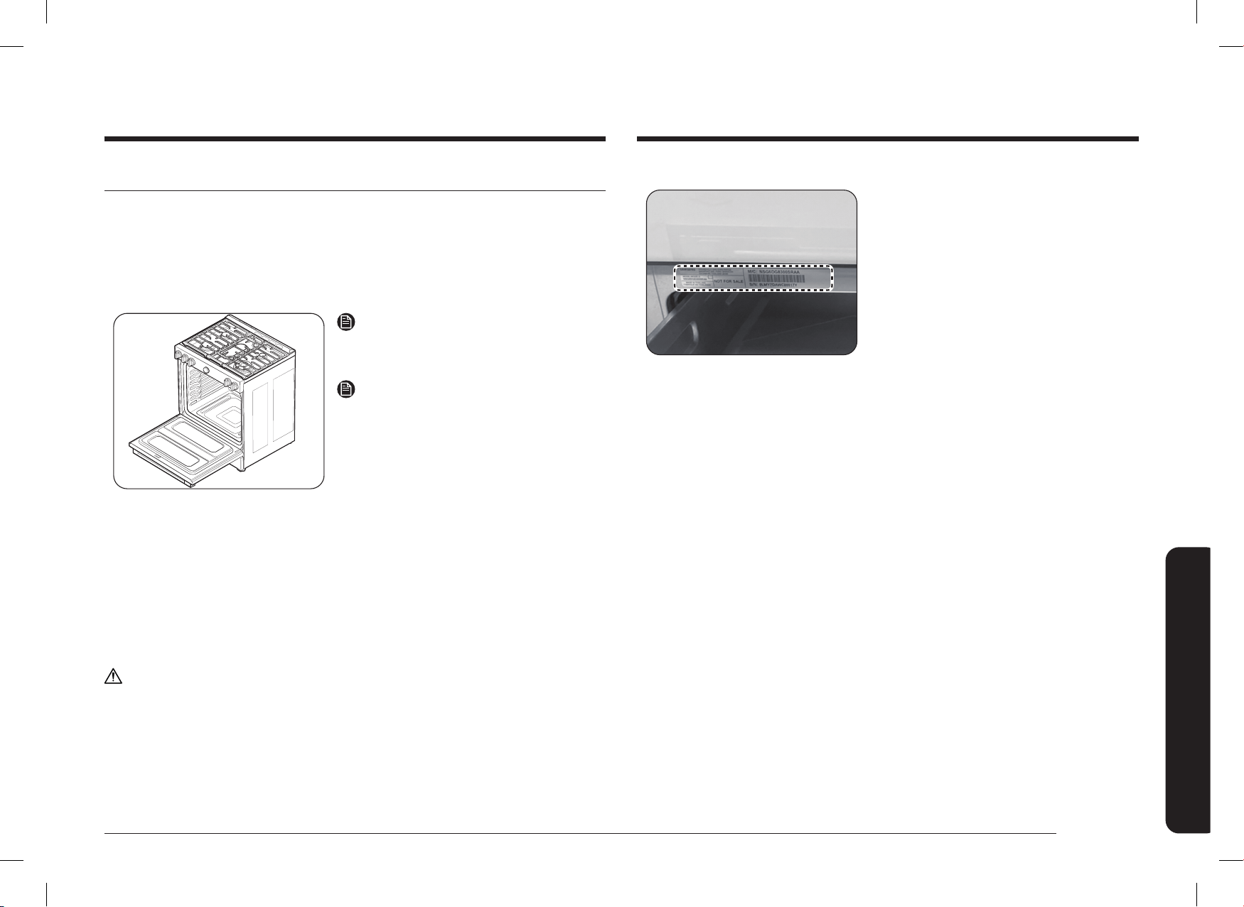
Español 17
Instrucciones de instalación
Instrucciones de instalación
Este artefacto debe ser alimentado con el voltaje
y la frecuencia adecuados, y conectado a un
circuito derivado individual debidamente con
conexión a tierra y protegido por un disyuntor o
fusible con el amperaje especicado en la placa.
La placa de especicaciones se encuentra arriba
del cajón en el marco del horno.
Le recomendamos que encargue la instalación
eléctrica de su estufa a un electricista calicado.
Después de la instalación, pídale a su electricista
que le muestre dónde está la desconexión
principal de la estufa.
Consulte a la empresa eléctrica local los códigos
eléctricos vigentes en su zona. Si no se realiza el
cableado en el horno de acuerdo con las normas
vigentes, pueden producirse situaciones de
peligro. Si no existen códigos locales, su estufa
debe estar cableada y con fusibles que cumplan
los requisitos del Código Eléctrico Nacional,
ANSI/NFPA N.º 70-Última edición. Puede obtener
una copia en la siguiente dirección:
Asociación Nacional de Protección contra
Incendios, Batterymarch Park Quincy, MA 02269
Desde el 1 de enero de 1996, el Código Eléctrico Nacional exige que las construcciones
nuevas (no existentes) se realicen con una conexión de 4 conductores a una estufa
eléctrica.
Cuando instale una estufa eléctrica en una construcción nueva, siga los pasos 2 y 3 para la
conexión de 4 cables.
Debe usar una CA de fase única con cables de 3 o 4 conductores. Sistema eléctrico de
208Y/120 voltios o 240/120 voltios, 60 hercios.
Si el servicio eléctrico suministrado no cumple las especicaciones anteriores, solicite a un
electricista autorizado que instale un tomacorriente aprobado.
Instalación de la estufa Dual Fuel
IMPORTANTE:
Lea las siguientes instrucciones, así como la sección “Instrucciones de seguridad
importantes” en la parte delantera de este manual, completa y cuidadosamente ANTES de
instalar o hacer funcionar la estufa a gas. La instalación, los ajustes, el servicio técnico o el
mantenimiento incorrectos pueden causar lesiones personales o daños materiales.
NOTA
Para pedir piezas o accesorios, comuníquese con
su vendedor local o consulte la última página.
NOTA
Para garantizar una instalación correcta, le
recomendamos que contrate a un instalador
profesional.
Paso 1. Desembale la estufa.
Retire todo el empaquetado. Si no quita todo el empaquetado, se puede dañar el artefacto.
Compruebe que estén todas las piezas sueltas comparándolas con los componentes de
Piezas suministradas en la página 10.
Verique que no haya habido daños durante el envío y que no falten piezas. Si falta alguna
pieza o hay algún daño, debe comunicárselo a su vendedor local.
Paso 2. Cumplir los requisitos de conexión eléctrica
PRECAUCIÓN
Por su seguridad personal, no utilice un alargue con este artefacto. Quite el fusible de la
casa o abra el disyuntor antes de comenzar la instalación.
DG68-01650A-02_IM_NSY6DG8550SRAA_EN+MES+CFR.indb 17DG68-01650A-02_IM_NSY6DG8550SRAA_EN+MES+CFR.indb 17 2024-12-03 오후 4:13:372024-12-03 오후 4:13:37
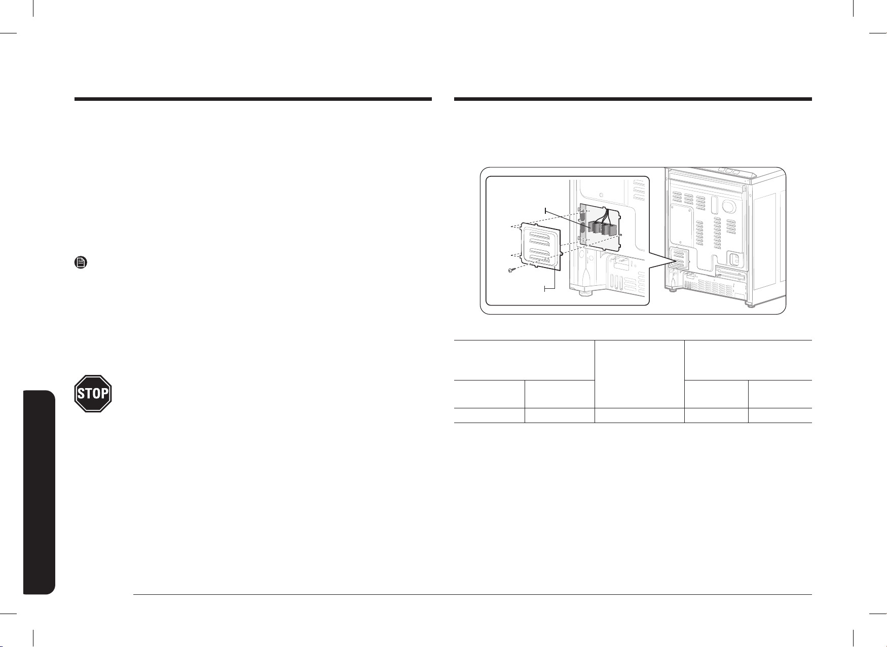
18 Español
Instrucciones de instalación
Instrucciones de instalación
Paso 3. Acceder a la conexión del cable de alimentación
Retire la tapa de acceso posterior y aoje el tornillo con un destornillador. Así tendrá
acceso al bloque de terminales.
Cubierta de acceso
Bloque de terminales
Potencia nominal especicada del kit de cable de alimentación
Potencia nominal, vatios
Potencia nominal
especicada del
kit de cable de
alimentación,
amperios
Diámetro (pulgadas) de la
abertura de conexión del
alcance
3 conductores
120/240 voltios
3 conductores
120/208 voltios
Cable de
alimentación
Conducto
8750-16500 7801-12500 40 o 50 A 1 ⅜" 1 ⅛"
Utilice únicamente un cable de estufa aprobado por UL de 3 o 4 conductores. Estos cables
pueden estar provistos de terminales de anillo en el cable y un dispositivo de alivio de
tensión.
Se requiere un cable de estufa de 40 amperios con un alcance mínimo de 125/250 voltios.
No se recomienda un cable de estufa de 50 amperios, pero si se utiliza, debe estar marcado
para su uso con aberturas de conexión de 1 ⅜ in de diámetro nominal. Se debe tener
cuidado de centrar el cable y el dispositivo de alivio de tensión dentro del oricio ciego
para evitar que el borde dañe el cable.
• Dado que no se puede acceder a los terminales de la estufa una vez colocada, se debe
utilizar un conducto o cable de servicio exible.
NOTA
• Si se utiliza un conducto, consulte el Paso 5 en las páginas 20 a
21.
• Si el cable de alimentación se enchufa de forma incorrecta, aparece el siguiente
mensaje en la pantalla.
- LCD, PMOLED: Wire installation fail (Falla en la instalación del conductor)
- LED: bAd LinE (Línea incorrecta)
• Reconecte el cable de alimentación de forma correcta para que el mensaje
desaparezca.
TODAS LAS CONSTRUCCIONES NUEVAS DE CIRCUITOS DERIVADOS, CASAS
RODANTES, VEHÍCULOS RECREATIVOS E INSTALACIONES EN LAS QUE LOS
CÓDIGOS LOCALES NO PERMITEN LA CONEXIÓN A TIERRA A TRAVÉS DEL
NEUTRO, REQUIEREN UN CABLE DE AUTONOMÍA DE 4 CONDUCTORES
APROBADO POR UL.
DG68-01650A-02_IM_NSY6DG8550SRAA_EN+MES+CFR.indb 18DG68-01650A-02_IM_NSY6DG8550SRAA_EN+MES+CFR.indb 18 2024-12-03 오후 4:13:372024-12-03 오후 4:13:37
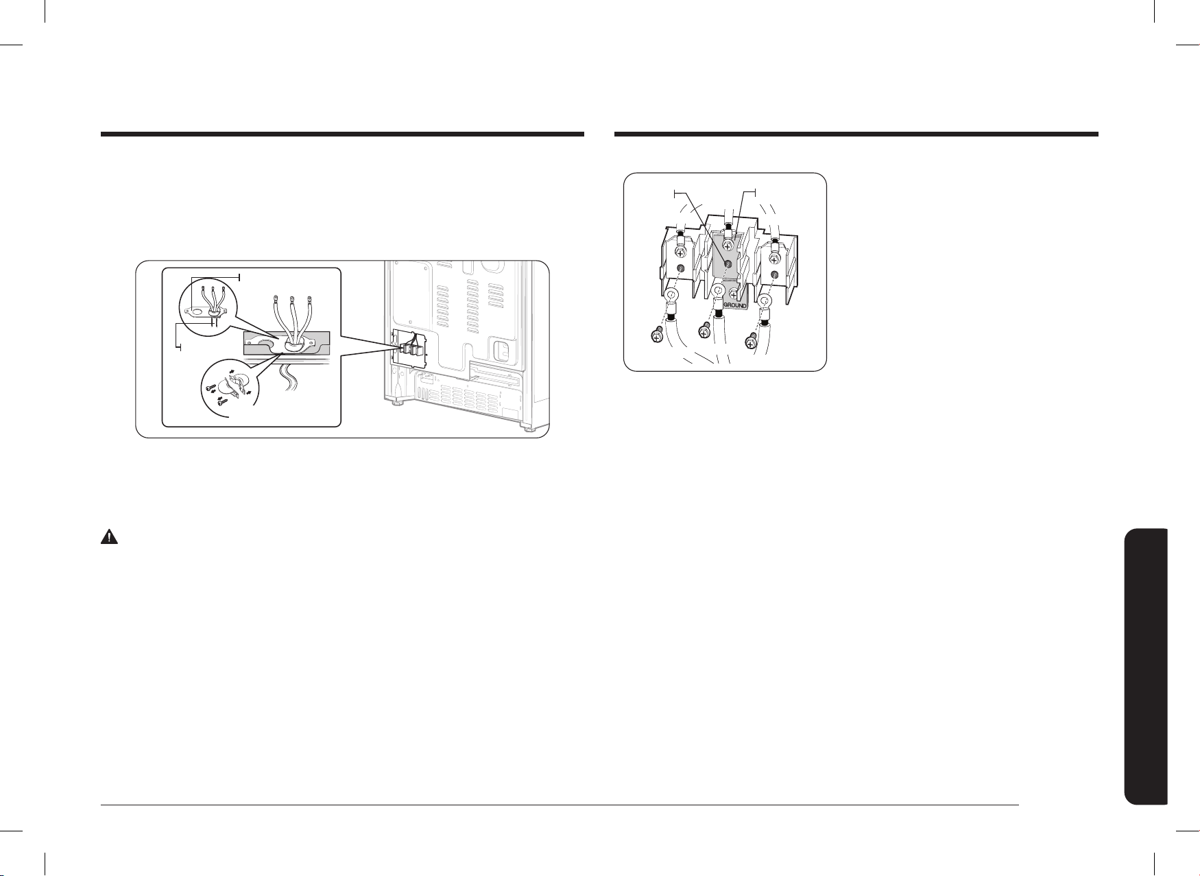
Español 19
Instrucciones de instalación
Correa de
conexión a tierra
Terminal
neutro
Negro
Blanco
Rojo
Negro
Blanco
Rojo
1. Retire los 3 tornillos del terminal inferior
del bloque de terminales.
2. Inserte los 3 tornillos de los terminales a
través de cada anillo terminal del cable de
alimentación y en los terminales inferiores
del bloque de terminales. Asegúrese de
que el cable central (blanco/neutro) esté
conectado a la posición central inferior del
bloque de terminales.
3. Ajuste los tornillos en el bloque de
terminales. NO retire la conexión de la
correa de conexión a tierra.
4. Vaya al Paso 6 en la página 22 y proceda
con la instalación.
Paso 4. Instalar el cable de alimentación
Para la instalación del cable de alimentación, enganche el aliviador de tensión sobre
el oricio del cable de alimentación (1 ⅜") situado debajo de la parte trasera del cajón.
Introduzca el cable de alimentación a través de la descarga de tracción y ajuste el
dispositivo.
Alivio de tensión
Cable de
alimentación
Placa de conexión del
conducto
• Debe instalar el cable de alimentación con un aliviador de tensión.
• Coloque el aliviador de tensión en la abertura de 1 ⅜" de la placa de conexión del
conducto.
Instalar un cable de alimentación de 3 conductores
ADVERTENCIA
El conductor neutro o de conexión a tierra del cable de alimentación debe conectarse al
terminal neutro situado en el centro del bloque de terminales. Los cables de alimentación
deben conectarse a los terminales inferior izquierdo e inferior derecho del bloque de
terminales.
DG68-01650A-02_IM_NSY6DG8550SRAA_EN+MES+CFR.indb 19DG68-01650A-02_IM_NSY6DG8550SRAA_EN+MES+CFR.indb 19 2024-12-03 오후 4:13:372024-12-03 오후 4:13:37

20 Español
Instrucciones de instalación
Instrucciones de instalación
Paso 5. Instalar el conducto
Retire la placa de conexión del conducto de la parte posterior del cajón y gírela como se
muestra a continuación.
Debe usarse el oricio del conducto (1 ⅛").
1 ⅛ in 1 ⅜ in
1 ⅛ in1 ⅜ in
1. Prepare el cable del conducto que se muestra en la Figura 1.
2. Instale el cable del conducto como se muestra en la Figura 2.
Placa de conexión del conducto
Alivio de tensión
Anillo
Cuerpo
Figura 2Figura 2
1"
3 ½"
⅜" 1"
3 ½"
3 cables3 cables 4 cables4 cables
Supercie ciega
Figura 1Figura 1
⅜"
Para instalaciones de conducto, inserte el dispositivo de alivio de tensión (no incluido) en el
oricio del conducto (1 ⅛ "). Luego, pase el cable del conducto por el cuerpo del dispositivo
de alivio de tensión y ajuste el anillo. Vuelva a instalar la ménsula.
Instalar un cable de alimentación de 4 conductores
ADVERTENCIA
El conductor neutro del circuito de suministro debe conectarse al terminal neutro situado
en el centro del bloque de terminales. Los cables de alimentación deben conectarse a los
terminales inferior izquierdo e inferior derecho del bloque de terminales. El cuarto cable
de conexión a tierra debe conectarse al marco de la estufa con la placa y el tornillo de
conexión a tierra.
Correa de
conexión a tierra
Placa de conexión
a tierra
Tornillo de
conexión a
tierra
Terminal
neutro
Cable de
conexión a tierra
(verde)
Blanco
Negro
Rojo
Negro
Blanco
Rojo
1. Retire los 3 tornillos del terminal inferior
del bloque de terminales. Retire el tornillo y
la placa de conexión a tierra y guárdelos.
2. Corte y tire la correa de conexión a tierra.
No deseche los tornillos.
3. Inserte el tornillo de conexión a tierra en el
anillo terminal del cable de alimentación, a
través de la placa de conexión a tierra, y en
el marco de la estufa.
4. Inserte los 3 tornillos de los terminales
(que había quitado antes) a través de cada
anillo terminal del cable de alimentación
y en los terminales inferiores del bloque
de terminales. Asegúrese de que el cable
central (blanco/neutro) está conectado a
la posición central inferior del bloque de
terminales. Ajuste los tornillos en el bloque
de terminales.
5. Vaya al Paso 6 en la página 22 y proceda
con la instalación.
DG68-01650A-02_IM_NSY6DG8550SRAA_EN+MES+CFR.indb 20DG68-01650A-02_IM_NSY6DG8550SRAA_EN+MES+CFR.indb 20 2024-12-03 오후 4:13:382024-12-03 오후 4:13:38
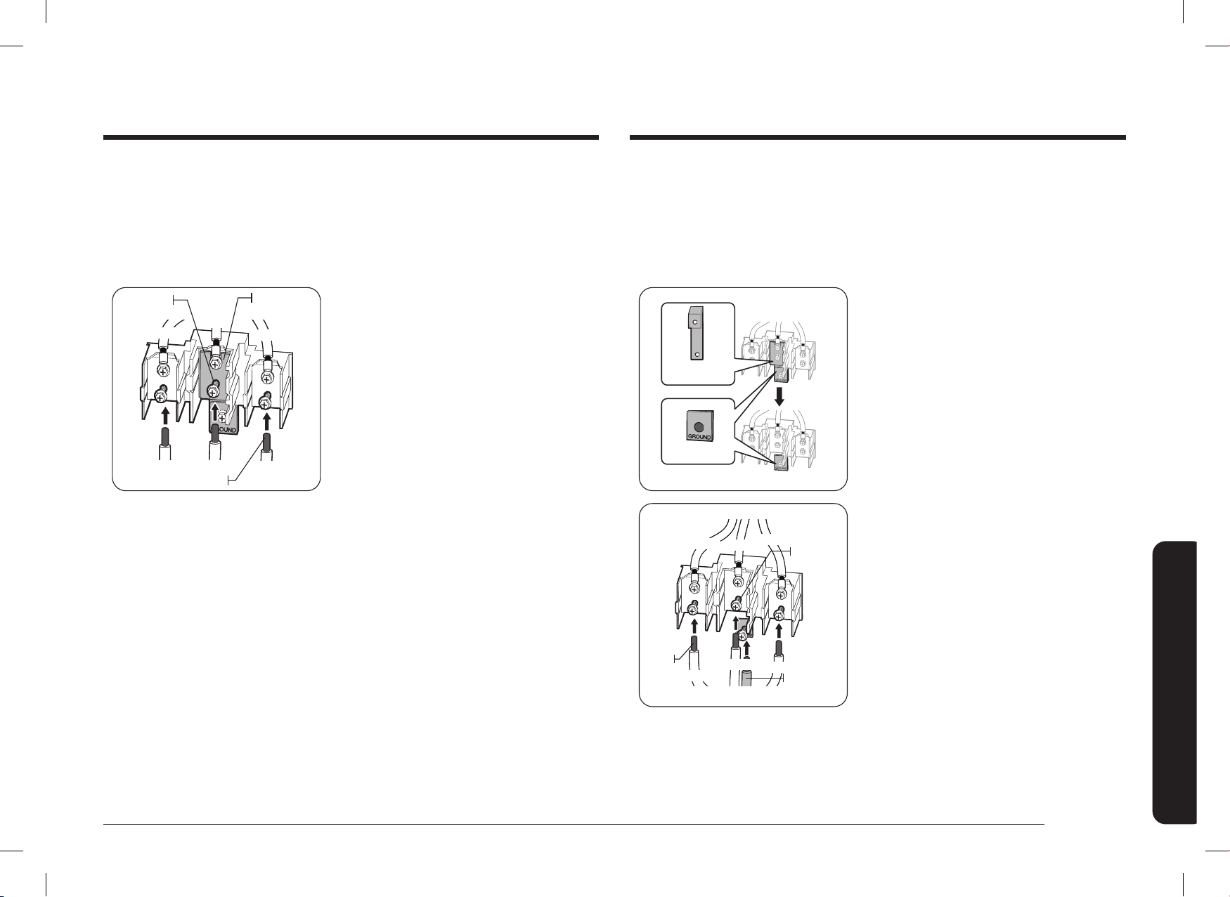
Español 21
Instrucciones de instalación
Instalar un conducto de 4 conductores
• Se puede utilizar cable de aluminio para la construcción, pero debe tener el amperaje
y la tensión adecuados para realizar la conexión. Conecte los cables según el Paso 4
en función de la cantidad de cables.
• El cableado utilizado, la ubicación y la caja de empalmes, etc., deben ajustarse a las
prácticas recomendadas de cableado y a los códigos locales.
Correa de
conexión a tierra
Placa de
conexión a tierra
Blanco
Negro
Rojo
Terminal
neutro
Cable de
conexión a
tierra (verde)
Puntas
del
cable
Blanco
Negro
Rojo
1. Aoje los 3 tornillos del terminal inferior
del bloque de terminales. Retire el tornillo y
la placa de tierra y guárdelos.
2. Corte y tire la correa de conexión a tierra.
No deseche los tornillos.
3. Introduzca la punta del cable pelado de
conexión a tierra entre el bastidor de
la estufa y la placa de conexión a tierra
(desmontada anteriormente). Luego fíjela
en su sitio con el tornillo de conexión a
tierra (desmontado anteriormente).
4. Introduzca la punta del cable pelado
(blanco/neutro) a través de la abertura
central inferior del bloque de terminales.
5. Inserte las dos puntas de los cables pelados
laterales en las aberturas del bloque de
terminales inferior izquierdo e inferior
derecho.
6. Apriete los tornillos hasta que el cable
quede rmemente sujeto (entre 35 y 50"-
lb). No ajuste los tornillos en exceso porque
puede dañar los cables.
7. Vaya al Paso 6 y proceda con la instalación.
Instalar un conducto de 3 conductores
• Se puede utilizar cable de aluminio para la construcción, pero debe tener el amperaje
y la tensión adecuados para realizar la conexión. Conecte los cables según el Paso 4
en función de la cantidad de cables.
• El cableado utilizado, la ubicación y la caja de empalmes, etc., deben ajustarse a las
prácticas recomendadas de cableado y a los códigos locales.
Blanco
Negro
Rojo
Correa de
conexión a tierra
Terminal
neutro
Puntas del cable
Rojo
Blanco
Negro
1. Aoje los 3 tornillos del terminal inferior
del bloque de terminales.
2. Introduzca la punta del cable pelado central
(blanco/neutro) a través de la abertura
central inferior del bloque de terminales.
En ciertos modelos, el cable tendrá que
insertarse a través de la abertura de la
correa de conexión a tierra y luego en la
abertura del bloque central inferior.
3. Inserte las dos puntas de los cables pelados
laterales en las aberturas del bloque de
terminales inferior izquierdo e inferior
derecho.
4. Apriete los tornillos hasta que el cable
quede rmemente sujeto (entre 35 y 50"-
lb). No ajuste los tornillos en exceso porque
puede dañar los cables.
5. Vaya al Paso 6 en la página 22 y proceda
con la instalación.
DG68-01650A-02_IM_NSY6DG8550SRAA_EN+MES+CFR.indb 21DG68-01650A-02_IM_NSY6DG8550SRAA_EN+MES+CFR.indb 21 2024-12-03 오후 4:13:382024-12-03 오후 4:13:38
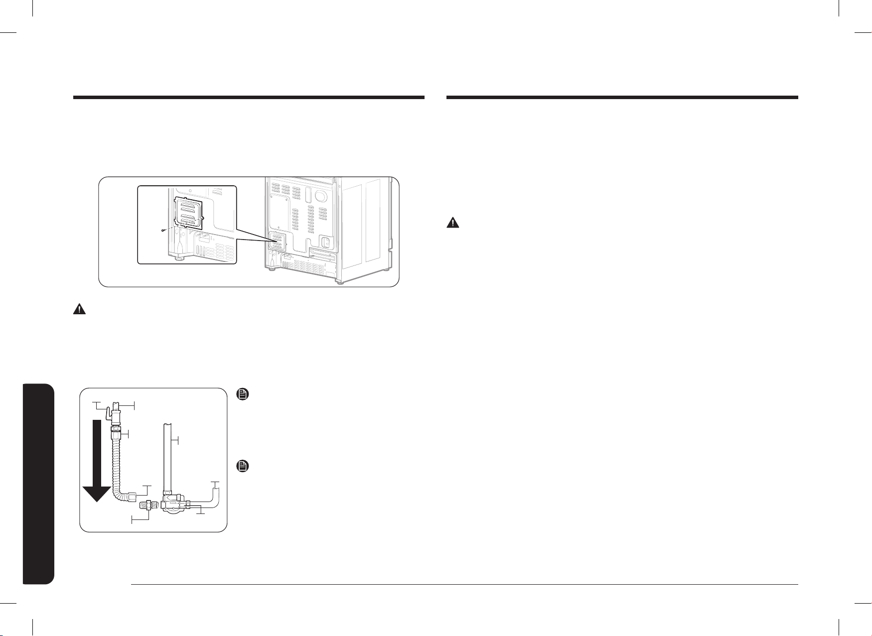
22 Español
Instrucciones de instalación
Instrucciones de instalación
Paso 7. Conectar la estufa al suministro de gas
Cierre la válvula principal de suministro de gas antes de desconectar la estufa anterior
y déjela cerrada hasta que se haya completado la nueva conexión. No olvide volver a
encender el piloto de otros artefactos de gas cuando vuelva a abrir el gas.
Debido a que las tuberías rígidas limitan el movimiento de la estufa, se recomienda usar
un conector exible de metal certicado por CSA International para electrodomésticos, a
menos que los códigos locales exijan una conexión con tuberías rígidas.
ADVERTENCIA
• No seguir las instrucciones de este manual con exactitud puede provocar un incendio
o una explosión que podría ocasionar daños materiales, lesiones o la muerte.
- No guarde ni utilice gasolina u otros productos inamables cerca de este
artefacto.
- QUÉ HACER SI HAY OLOR A GAS:
• NO prenda fósforos, velas o cigarrillos.
• NO encienda ningún otro artefacto.
• NO toque ningún interruptor eléctrico.
• NO utilice ningún teléfono dentro del edicio.
• Evacúe la habitación, el edicio o el área.
• Llame inmediatamente al proveedor de gas desde el teléfono de un vecino. Siga las
instrucciones del proveedor de gas.
• Si no puede comunicarse con el proveedor de gas, llame al departamento de
bomberos.
- La instalación y el servicio técnico deben ser realizados por el proveedor de gas,
o un instalador o agencia de servicio técnico calicados.
Paso 6. Reemplazar la cubierta de acceso
Reemplace la cubierta de acceso en la parte trasera de la estufa. Para reemplazar la
cubierta del cable, inserte las dos pestañas en los bolsillos ubicados debajo de la abertura y
ajuste el tornillo.
ADVERTENCIA
No exceda los 25 pie-libra de torque cuando haga las conexiones de la línea de gas.
Si ajusta en exceso puede romper el regulador de presión y generar una fuga de gas.
Conexión con conectores exibles
Instalador: informe la ubicación de la válvula de cierre de gas al consumidor.
Adaptador
Conector
exible
(6 pies máx.)
Adaptador
Válvula de cierre de gas
Tubería de gas de 0.5 pulg.
o 0.75 pulg.
Tubería de la
válvula de control
del quemador del
horno
Flujo de gas a la estufa
Regulador
de presión
Tubería hacia
el colector de
control de la placa
de cocción
NOTA
Si su zona requiere una conexión de tubería
rígida, póngase en contacto con un instalador
calicado, una agencia de servicios o un
proveedor de gas.
NOTA
La válvula de cierre de gas debe instalarse en
un lugar de la tubería de gas que sea accesible,
fuera del artefacto, para poder abrir o cerrar el
suministro de gas al dispositivo.
DG68-01650A-02_IM_NSY6DG8550SRAA_EN+MES+CFR.indb 22DG68-01650A-02_IM_NSY6DG8550SRAA_EN+MES+CFR.indb 22 2024-12-03 오후 4:13:392024-12-03 오후 4:13:39

Español 23
Instrucciones de instalación
Paso 8. Convertir a gas LP (opcional)
Todas las estufas a gas nuevas se envían conguradas de fábrica para usar con gas natural.
Cualquier estufa a gas de Samsung se puede convertir para usar gas LP. Consulte la
página 57 del Manual del usuario para comunicarse con un técnico de servicio calicado.
El proceso de conversión solo debe realizarlo un instalador de gas LP calicado.
Las instrucciones de conversión y los oricios de LP se suministran con el kit de conversión
a LP. La conversión a LP exige que se cambien todos los oricios de quemador (5
quemadores superciales).
Además, es necesario invertir la boquilla del regulador de presión de gas. Todos los
oricios sustituidos deben quedar en poder del consumidor, incluidas las instrucciones, los
tamaños de retroinstalación y la indicación del oricio.
Compruebe la calidad de la llama de todos los quemadores tras la conversión a gas LP.
Nunca use un conector viejo al instalar una estufa nueva. Para las tuberías rígidas, alinee
cuidadosamente la tubería. La estufa no se puede mover después de realizarse la conexión.
Para evitar fugas de gas, aplique compuesto para unión de tuberías o envuelva con cinta
para roscas de tubos con Teón en todas las roscas macho (externas).
1. Instale una válvula manual de cierre en la tubería de gas en un lugar de fácil acceso
fuera de la estufa.
Asegúrese de que todas las personas que utilicen la estufa sepan desde dónde y cómo
cerrar el suministro de gas a la estufa.
2. Instale el adaptador de unión cónica macho de 0.5 pulgadas (1.3 cm) en la rosca
interna NPT de 0.5 pulgadas (1.3 cm) de la entrada del regulador. Utilice una llave de
seguridad al ajustar el regulador para evitar daños.
Cuando instale la estufa por delante, retire el codo de 90° para facilitar la instalación.
3. Instale un adaptador de unión cónica macho de 0.5 pulgadas (1.3 cm) o de
0.75 pulgadas (1.9 cm) en la rosca interna NPT de la válvula de cierre manual y
recuerde sujetar la válvula de cierre para evitar que gire.
4. Conecte el conector metálico exible al adaptador de la estufa. Posicione la estufa
para permitir la conexión en la válvula de cierre.
5. Una vez realizadas todas las conexiones, asegúrese de que todos los controles de la
estufa estén en la posición off (apagado) y abra la válvula principal de suministro
de gas. Utilice un detector de fugas de líquido en todas las juntas y conexiones para
comprobar si hay fugas en el sistema.
ADVERTENCIA
Para prevenir incendios, explosiones, lesiones o muertes, NO utilice una llama para
comprobar si hay fugas de gas.
Cuando utilice presiones de prueba superiores a ½ psig para probar la presión del sistema
de suministro de gas de la residencia, desconecte la estufa y la válvula de cierre individual
de la tubería de suministro de gas. Cuando utilice presiones de prueba de ½ psig o menos
para probar el sistema de suministro de gas, simplemente aísle la estufa del sistema de
suministro de gas cerrando la válvula de cierre individual.
DG68-01650A-02_IM_NSY6DG8550SRAA_EN+MES+CFR.indb 23DG68-01650A-02_IM_NSY6DG8550SRAA_EN+MES+CFR.indb 23 2024-12-03 오후 4:13:392024-12-03 오후 4:13:39
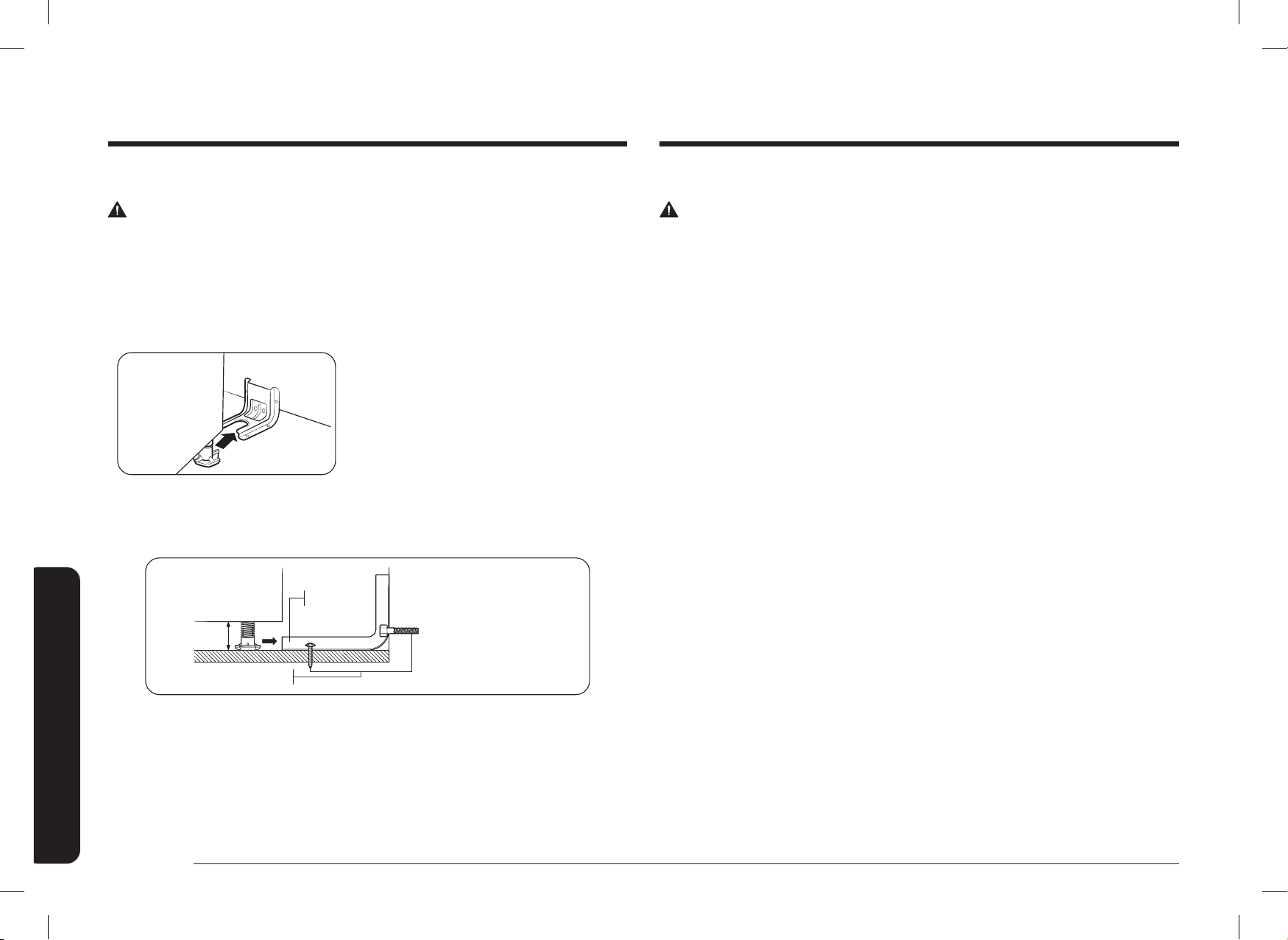
24 Español
Instrucciones de instalación
Instrucciones de instalación
Paso 10. Enchufar y colocar
ADVERTENCIA
ANTES DE OPERAR O PROBAR, siga los requisitos de conexión a tierra de las
páginas 15 y 16 de este manual. Una conexión a tierra inadecuada puede causar riesgo de
descarga eléctrica.
• Todas las estufas Dual Fuel vienen con un cable de alimentación. El cable de
alimentación está conectado a la parte trasera de la estufa. Consulte la sección
"Requisitos eléctricos" en las páginas 15 y 16.
• El sistema eléctrico, incluido el cable de alimentación, viene preinstalado y
precableado de fábrica. Modicar cualquier parte de este sistema puede provocar un
cortocircuito o una sobrecarga.
1. Enchufe el cable de alimentación. Asegúrese de que el tomacorriente cumpla con los
códigos eléctricos locales o nacionales, tal y como se indica en las páginas 15 y 16.
2. Deslice la estufa hacia su lugar.
3. Compruebe que la tubería de suministro de gas no ha sufrido daños y que ha
permanecido conectada durante la colocación.
4. Compruebe que la pata trasera de la estufa se haya deslizado por la ménsula
antinclinación. Con cuidado, incline la estufa hacia adelante para vericar que la
ménsula antinclinación engancha el soporte trasero e imposibilita el vuelco.
Paso 9. Instalar la ménsula antinclinación
ADVERTENCIA
Para reducir el riesgo de inclinación, el aparato debe jarse instalando correctamente la
ménsula antinclinación embalada con el artefacto.
• Todas las estufas pueden inclinarse y provocar lesiones.
• La inclinación de las estufas puede causar quemaduras por derrames, lesiones o la muerte.
• Para evitar la inclinación accidental, instale y revise la ménsula antinclinación siguiendo
las instrucciones y las plantillas que vienen con ella.
Con cada estufa se suministran una ménsula
antinclinación y tornillos, instrucciones de
instalación y una plantilla (PN DG94-00870B).
Las instrucciones incluyen la información
necesaria para completar la instalación de
la ménsula antinclinación. Lea y siga las
instrucciones de la hoja y utilice la plantilla
para la instalación de la ménsula antinclinación.
En caso de no instalarse correctamente, la
estufa podría inclinarse si usted o un niño se
pusieran de pie, se sentaran o se apoyaran
sobre la puerta abierta del horno.
Ménsula
antinclinación
* aproximadamente
21/32 in (16.5 mm)
El tornillo debe entrar
en madera u hormigón
*NOTA: Para instalar la ménsula
antinclinación libere la pata
niveladora.
Se requiere una distancia mínima
de 21/32 in (16.5 mm) entre la parte
inferior de la estufa y el suelo de
la cocina.
Para comprobar si la ménsula está instalada y encajada correctamente, retire el cajón de
almacenamiento y mire debajo de la estufa para ver si la pata niveladora está encajada en
la ménsula. Incline cuidadosamente la estufa hacia adelante. La ménsula debe impedir que
la estufa se incline más 4" (10.2 cm). Si no lo hace, se debe volver a instalar la ménsula.
Si la estufa se separa de la pared por cualquier motivo, repita siempre este procedimiento
para comprobar que la estufa está bien sujeta por la ménsula antinclinación. No retire
nunca por completo las patas de nivelación o la estufa no quedará bien sujeta a la ménsula
antinclinación.
DG68-01650A-02_IM_NSY6DG8550SRAA_EN+MES+CFR.indb 24DG68-01650A-02_IM_NSY6DG8550SRAA_EN+MES+CFR.indb 24 2024-12-03 오후 4:13:392024-12-03 오후 4:13:39
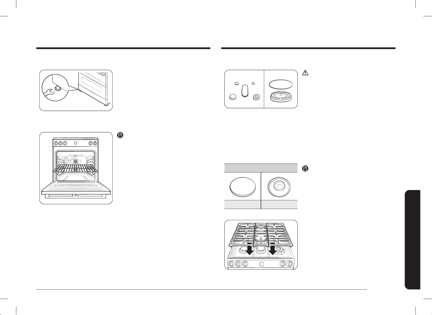
Español 25
Instrucciones de instalación
Paso 12. Arme los quemadores superciales
PRECAUCIÓN
No opere los quemadores superciales si no
están todas las piezas en su lugar.
1. Coloque los cabezales de los quemadores
superciales en la parte superior de los
colectores para los quemadores superiores,
tal como se indica a la derecha.
Los electrodos encajarán en la ranura de la
parte inferior de los cabezales.
Asegúrese de que los cabezales de los
quemadores superciales estén planos y
paralelos a la placa de cocción.
2. Coloque las tapas del mismo tamaño
en la parte superior de cada cabezal de
quemador supercial.
Quemador de fuego lento preciso (RR)
Supercie plana Línea cóncava
NOTA
Las tapas del quemador de fuego lento preciso
(RR) y del quemador doble interno (RF) se
pueden intercambiar.
3. Coloque las rejillas de los quemadores
superciales izquierdo, central y derecho
sobre la placa de cocción. Los bordes de las
rejillas deben coincidir con los bordes de la
placa de cocción.
Paso 11. Nivelar la estufa
Pata niveladora
1. Asegúrese de que la estufa está colocada
donde usted quiere.
2. Con una llave inglesa, nivele la estufa
girando las patas niveladoras delanteras
hacia dentro o hacia fuera según sea
necesario. En sentido contrario a las agujas
del reloj se acorta la pata y se baja la
estufa. En el sentido de las agujas del reloj
se alarga la pata y se eleva la estufa.
NOTA
• El ajuste de las dos patas delanteras suele
ser suciente, pero puede ajustar las cuatro
patas si es necesario.
• Ajuste las patas niveladoras solo lo
necesario para nivelar la estufa.
Extender las patas de nivelación más de lo
necesario o retirar las patas puede hacer
que la posición de la estufa sea inestable.
3. Si la estufa está ubicada al lado de
gabinetes o entre ellos, asegúrese de que
la placa de cocción (sin las rejillas de los
quemadores superciales) esté nivelada con
las mesadas.
4. Coloque una parrilla de horno en la posición
de la rejilla central.
5. Utilice las dos posiciones que se muestran
a la derecha para comprobar el nivel de la
estufa con un nivel de carpintería.
6. Una vez que la estufa esté nivelada, separe
la estufa de la pared para poder instalar la
ménsula antinclinación.
DG68-01650A-02_IM_NSY6DG8550SRAA_EN+MES+CFR.indb 25DG68-01650A-02_IM_NSY6DG8550SRAA_EN+MES+CFR.indb 25 2024-12-03 오후 4:13:402024-12-03 오후 4:13:40
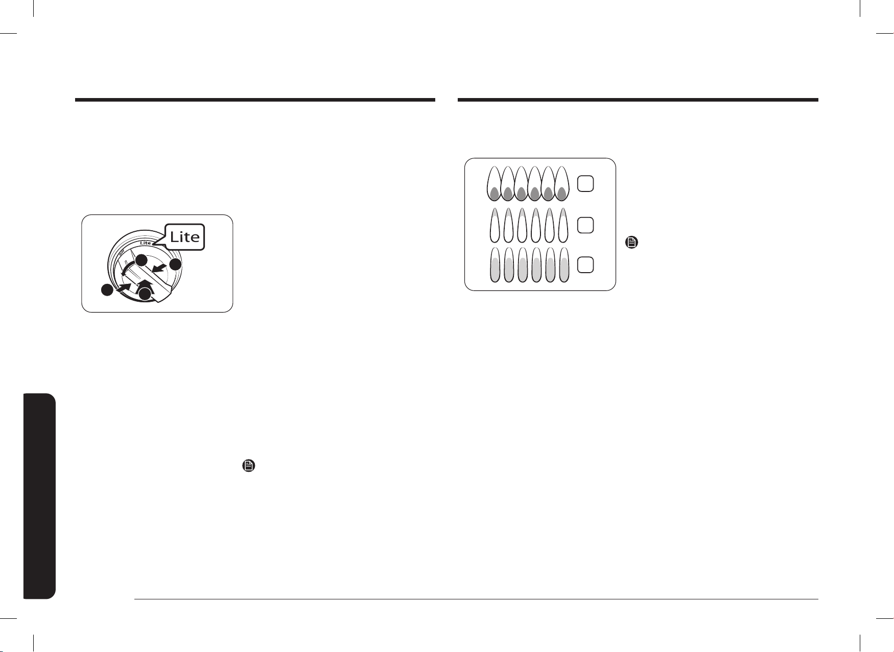
26 Español
Instrucciones de instalación
Instrucciones de instalación
Vericación de la calidad de la llama:
Todas las llamas de combustión deben vericarse visualmente para determinar su calidad.
2
3
1
1. Llamas azules atenuadas: normal para la
operación de gas natural.
2. Puntas amarillas en los conos exteriores:
normal para la operación de gas LP.
3. Llamas amarillas: no son normales para
ningún tipo de gas.
NOTA
Si la llama del quemador se parece a la opción 3,
no se debe utilizar la estufa hasta que se revise.
Llame al servicio técnico. Las llamas de un
quemador normal deben lucir como las opciones
1 o 2, según el tipo de gas que utilice.
Paso 13. Compruebe el encendido de los quemadores superciales.
Compruebe el funcionamiento de todos los quemadores de la placa de cocción y del horno
después de haber instalado y montado la estufa, comprobado cuidadosamente que las
tuberías de suministro de gas no presentan fugas y enchufado el cable de alimentación
eléctrica.
Todos los quemadores superciales y del horno tienen encendido electrónico.
3
2
1
1
Para encender un quemador supercial:
1. Presione el botón integrado en la perilla.
2. Presione la perilla de control de ese
quemador supercial y gírela hacia la
posición Lite (Encender). El sonido de
“chasquido” indica que el sistema de
encendido electrónico está funcionando
correctamente.
El quemador se encenderá en unos
4 segundos, una vez purgado el aire de la
línea de alimentación.
3. Cuando el quemador esté encendido, gire
la perilla de control a la posición deseada.
El sonido de “chasquido” se detendrá y la
altura de la llama cambiará de máximo a
mínimo mientras gira la perilla de control.
4. Repita los pasos 1, 2 y 3 sucesivamente en
cada quemador supercial para comprobar
que funcionen correctamente.
NOTA
Coloque la comida en el horno después de
precalentarlo, si así lo requiere la receta.
El precalentamiento es importante para obtener
buenos resultados de horneado. Cuando el
horno haya alcanzado la temperatura de cocción
deseada, emitirá una señal sonora.
DG68-01650A-02_IM_NSY6DG8550SRAA_EN+MES+CFR.indb 26DG68-01650A-02_IM_NSY6DG8550SRAA_EN+MES+CFR.indb 26 2024-12-03 오후 4:13:402024-12-03 오후 4:13:40

Español 27
Instrucciones de instalación
Para ajustar la posición baja de la llama
Identique en qué quemador la velocidad de cocción a fuego lento es demasiado alta o
demasiado baja a través de los grácos del panel de elementos.
Tornillo de ajuste
de simulación
1. Gire una perilla a la posición Lo (Bajo) y
retire la perilla del vástago de la válvula
mientras la llama está encendida.
Destornillador
pequeño
Vástago de la válvula
2. Empuje con cuidado el destornillador en
el vástago de la válvula, hasta que choque
con el tornillo de ajuste de simulación.
Asegúrese de que la cabeza plana del
destornillador está asentada en la ranura
del tornillo de jación.
3. Gire el tornillo de ajuste de la válvula
en el sentido de las agujas del reloj para
disminuir la salida de llama de ajuste
Lo (Bajo) o gire el tornillo de ajuste en
sentido contrario a las agujas del reloj para
aumentar la salida de llama de ajuste Lo
(Bajo).
ADVERTENCIA
1. No retire completamente el tornillo de ajuste de la válvula del vástago de la válvula.
No aoje más de 3 vueltas del tornillo de ajuste de la válvula. El tornillo de ajuste de
la válvula forma parte del conjunto de la válvula de gas.
Si se retira el tornillo de ajuste de la válvula, se producirá una fuga de gas.
2. Después de ajustar el tornillo de ajuste de la válvula, inspeccione el conjunto en busca
de fugas de gas.
Paso 14. Lista de vericación nal de la instalación
Ya completó la instalación de su estufa. Asegúrese de que todos los controles estén en la
posición Apagado y que el ujo de aire de ventilación hacia la estufa no esté obstruido.
La siguiente es una lista de vericación para conrmar que su estufa está instalada de
forma segura y lista para su operación.
La línea de gas se conectó correctamente a la estufa. El gas se encendió. Se vericaron
todas las conexiones en busca de pérdidas.
La estufa está enchufada en el receptáculo que está correctamente conectado a tierra.
Se instaló y se jó correctamente la ménsula antinclinación aprobada con la estufa.
La estufa está nivelada y se encuentra rme sobre una supercie sólida al nivel del
suelo.
Los quemadores superciales de gas se han montado correctamente.
Se probaron todos los quemadores y funcionan correctamente.
DG68-01650A-02_IM_NSY6DG8550SRAA_EN+MES+CFR.indb 27DG68-01650A-02_IM_NSY6DG8550SRAA_EN+MES+CFR.indb 27 2024-12-03 오후 4:13:402024-12-03 오후 4:13:40

¿TIENE PREGUNTAS O COMENTARIOS?
PAÍS CENTRO DE CONTACTO SITIO WEB
U.S.A
Consumer Electronics
1-800-SAMSUNG (726-7864) www.samsung.com/us/support
CANADA 1-800-SAMSUNG(726-7864)
www.samsung.com/ca/support (English)
www.samsung.com/ca_fr/support (French)
DG68-01650A-02
Escanee el código QR* o visite
www.samsung.com/spsn para
ver nuestros útiles videos de
procedimientos y espectáculos en
directo
* Requiere la instalación de un lector en su
teléfono inteligente.
Escanee este código con su
teléfono inteligente
DG68-01650A-02_IM_NSY6DG8550SRAA_EN+MES+CFR.indb 28DG68-01650A-02_IM_NSY6DG8550SRAA_EN+MES+CFR.indb 28 2024-12-03 오후 4:13:402024-12-03 오후 4:13:40
Cuisinière à deux combustibles
Manuel d’installation
NSY6
**
8
*
5
***
DG68-01650A-02_IM_NSY6DG8550SRAA_EN+MES+CFR.indb 1DG68-01650A-02_IM_NSY6DG8550SRAA_EN+MES+CFR.indb 1 2024-12-03 오후 4:13:412024-12-03 오후 4:13:41
2 Français
Contenu
Contenu
Démarrer 3
Informations de sécurité importantes 4
Lisez toutes les instructions avant d’utiliser cet appareil 4
Symboles utilisés dans ce manuel 4
Avertissement relatif à la proposition 65 de l’État de Californie 4
Commonwealth du Massachusetts 4
Sécurité générale 4
Sécurité incendie 5
Sécurité en matière de gaz 5
Sécurité électrique et mise à la terre 6
Sécurité de l’installation 6
Sécurité en matière d’emplacement 7
Sécurité de la table de cuisson 7
Sécurité du four 8
Sécurité du tiroir de rangement 9
Sécurité du four auto-nettoyant 9
Composants de la cuisinière à deux combustibles 10
Contenu de la boîte 10
Conditions d’installation 11
Exigences relatives à l’emplacement 11
Pour éviter tout bris 14
Exigences en matière de gaz 15
Exigences particulières en matière de gaz (modèles à gaz vendus dans le Massachusetts) 15
Exigences électriques 16
AVERTISSEMENT
Si les informations contenues dans ce manuel ne sont pas strictement
respectées, un incendie ou une explosion peuvent se produire et
entraîner des dommages matériels, des blessures ou la mort.
• Veillez à NE PAS conserver ni utiliser d’essence ou d’autres vapeurs ou liquides
inammables près de cet appareil ou de tout autre appareil.
• QUE FAIRE SI VOUS SENTEZ UNE ODEUR DE GAZ :
- Veillez à NE PAS mettre en marche un appareil.
- Veillez à NE PAS toucher aux interrupteurs électriques.
- Veillez à NE PAS utiliser de téléphone dans votre bâtiment.
- Appelez immédiatement votre compagnie de gaz depuis le téléphone d’un
voisin. Suivez les instructions de la compagnie de gaz.
- Si votre fournisseur de gaz n’est pas joignable, appelez les pompiers.
• L’installation et l’entretien doivent être effectués par un installateur qualié, un
organisme de service ou la compagnie de gaz.
Dispositif anti-basculement
AVERTISSEMENT
TOUTES LES CUISINIÈRES PEUVENT BASCULER ET ENTRAÎNER DES
BLESSURES CORPORELLES.
LES CUISINIÈRES QUI BASCULENT PEUVENT PROVOQUER DES BRÛLURES
DUES À DES DÉVERSEMENTS, DES BLESSURES ET/OU LA MORT.
INSTALLEZ ET VÉRIFIEZ LE SUPPORT ANTI-BASCULEMENT EN SUIVANT LES
INSTRUCTIONS ET LE MODÈLE FOURNIS AVEC LE SUPPORT.
• Pour éviter le basculement accidentel de la cuisinière, xez un dispositif anti-
basculement approuvé au sol. (Voir Installation du dispositif anti-basculement
dans les instructions d’installation). Vériez si la cuisinière est bien installée en la
faisant basculer prudemment vers l’avant. Le dispositif anti-basculement devrait
s’enclencher et empêcher la cuisinière de basculer.
• Si la cuisinière est retirée du mur pour une quelconque raison, assurez-vous que le
dispositif anti-basculement est réenclenché après avoir remis la cuisinière en place.
• Suivez les instructions d’installation gurant dans le manuel d’installation. Le non-
respect de ces instructions peut entraîner la mort, des blessures graves et/ou des
dommages matériels.
• Pour éviter tout basculement accidentel de la cuisinière, veuillez NE PAS marcher,
s’asseoir ou s’appuyer sur la porte ou le tiroir.
• Faites un technicien qualié vérier si votre appareil est bien installé et mis à la
terre.
DG68-01650A-02_IM_NSY6DG8550SRAA_EN+MES+CFR.indb 2DG68-01650A-02_IM_NSY6DG8550SRAA_EN+MES+CFR.indb 2 2024-12-03 오후 4:13:412024-12-03 오후 4:13:41

Français 3
Démarrer
Instructions d’installation 17
Installation de votre cuisinière à deux combustibles 17
Étape 1 : Déballez la cuisinière 17
Étape 2 : Satisfaire aux exigences de branchement électrique 17
Étape 3 : Accès au raccord du cordon d’alimentation 18
Étape 4 : Installation du cordon d’alimentation 19
Étape 5 : Installation du conduit 20
Étape 6 : Remplacement du panneau d’accès 22
Étape 7 : Branchement de la cuisinière à l’alimentation en gaz 22
Étape 8 : Conversion au GPL (en option) 23
Étape 9 : Installation du dispositif anti-basculement 24
Étape 10 : Branchement et pose 24
Étape 11 : Mettre à niveau la cuisinière 25
Étape 12 : Assemblage des brûleurs de surface 25
Étape 13 : Vériez l’allumage des brûleurs de surface 26
Étape 14 : Liste de contrôle de l’installation nale 27
À PROPOS DE CE MANUEL
LISEZ ENTIÈREMENT ET ATTENTIVEMENT CES INSTRUCTIONS.
REMARQUE IMPORTANTE DESTINÉE À L’INSTALLATEUR
• Lisez toutes les instructions contenues dans ce manuel d’installation avant d’installer la
cuisinière.
• Retirez tous les matériaux d’emballage des compartiments du four avant de raccorder
l’alimentation électrique et en gaz à la cuisinière.
• Respectez tous les codes et ordonnances en vigueur.
• Veillez bien à laisser ces instructions à l’utilisateur.
• L’installation de cet appareil requiert des compétences mécaniques de base.
• L’installateur est responsable de toute mauvaise installation.
• La défaillance du produit due à une installation incorrecte n’est pas couverte par la
garantie.
REMARQUE IMPORTANTE DESTINÉE À L’UTILISATEUR
Conservez ces instructions avec votre mode d’emploi pour référence ultérieure.
• Comme pour l’utilisation de tout appareil générant de la chaleur, vous devez respecter
certaines précautions de sécurité.
• Assurez-vous que votre cuisinière est installée et mise à la terre correctement par un
installateur ou un technicien qualié.
• Assurez-vous que les revêtements muraux autour de la cuisinière peuvent résister à la
chaleur générée par l’appareil.
• L’espace de rangement au-dessus des brûleurs de surface doit être d’au moins 76,2 cm
(30 po).
REMARQUE IMPORTANTE À L’INTENTION DU RÉPARATEUR
Le schéma électrique se trouve dans une enveloppe xée à l’arrière de la cuisinière.
Démarrer
DG68-01650A-02_IM_NSY6DG8550SRAA_EN+MES+CFR.indb 3DG68-01650A-02_IM_NSY6DG8550SRAA_EN+MES+CFR.indb 3 2024-12-03 오후 4:13:412024-12-03 오후 4:13:41
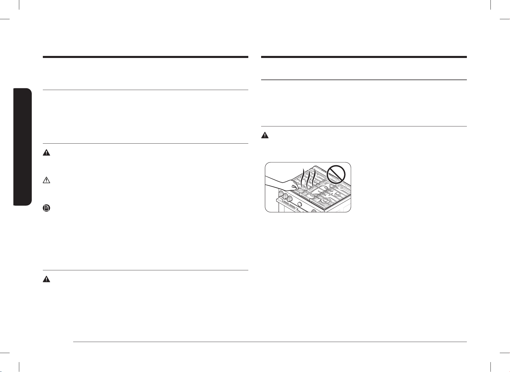
4 Français
Informations de sécurité importantes
Informations de sécurité importantesInformations de sécurité importantes
LISEZ TOUTES LES INSTRUCTIONS AVANT D’UTILISER CET
APPAREIL
• Tout appareil électrique ou au gaz comportant des pièces mobiles peut être dangereux.
Veuillez lire les consignes de sécurité importantes relatives à cet appareil dans ce manuel.
Les instructions doivent être suivies pour minimiser les risques de blessures, de décès ou
de dommages matériels.
• Conservez ce manuel. Ne le jetez pas.
SYMBOLES UTILISÉS DANS CE MANUEL
AVERTISSEMENT
Risques ou manipulations dangereuses susceptibles d’entraîner des blessures graves, voire la
mort.
ATTENTION
Risques ou manipulations dangereuses susceptibles d’entraîner des blessures légères ou des
dégâts.
REMARQUE
Conseils et instructions utiles.
Ces icônes et symboles d’avertissement sont là pour éviter de vous blesser ou de blesser
d’autres personnes. Veuillez les suivre explicitement. Après avoir lu cette section, conservez-la
dans un endroit sûr pour pouvoir la consulter ultérieurement.
AVERTISSEMENT RELATIF À LA PROPOSITION 65 DE L’ÉTAT
DE CALIFORNIE
AVERTISSEMENT
Cancer et troubles de la fertilité – www.P65Warnings.ca.gov
COMMONWEALTH DU MASSACHUSETTS
• Ce produit doit être installé par un plombier agréé ou un installateur de gaz qualié ou
agréé par l’État du Massachusetts. Lorsque vous utilisez des vannes à bille pour couper
le gaz, il faut utiliser le type à poignée en T. Il est interdit de raccorder en série plusieurs
conduites de gaz exibles.
SÉCURITÉ GÉNÉRALE
AVERTISSEMENT
Pour réduire les risques d’incendie, d’électrocution, de blessures corporelles et/ou de décès,
respectez les précautions suivantes.
• Ne touchez aucune partie de la cuisinière, y
compris, mais sans s’y limiter, les brûleurs du
four, les brûleurs de surface ou les surfaces
intérieures pendant ou immédiatement après
la cuisson.
• Repérez la vanne d’arrêt du gaz et sachez
comment la fermer.
• Assurez-vous que le dispositif anti-basculement est correctement installé sur la cuisinière.
Consultez les instructions d’installation pour obtenir des informations supplémentaires.
• Ne laissez pas les enfants s’approcher de la cuisinière, y entrer ou y travailler. Ne laissez
pas les enfants jouer avec la cuisinière ou avec des parties de celle-ci. Ne laissez pas les
enfants sans surveillance dans une zone où la cuisinière est en cours d’utilisation.
Pour des raisons de sécurité, nous vous recommandons d’utiliser la fonction de verrouillage
des commandes et des portes.
• Retirez tous les matériaux d’emballage de la cuisinière avant de la faire fonctionner an
d’éviter l’inammation de ces matériaux. Gardez tous les matériaux d’emballage hors de
portée des enfants. Mettez au rebut les matériaux d’emballage de manière appropriée après
avoir déballé la cuisinière.
• Ne rangez pas d’objets susceptibles d’intéresser les enfants sur la table de cuisson ou sur le
panneau arrière de la cuisinière. Les enfants qui grimpent sur la cuisinière pour atteindre
des objets sont susceptibles de se retrouver tués ou gravement blessés.
• Ne mettez pas la cuisinière en marche si celle-ci ou une partie de celle-ci est endommagée,
si elle fonctionne mal ou s’il manque des pièces.
• N’utilisez pas la cuisinière comme chauffage d’appoint. Cette cuisinière ne doit être utilisée
que pour la cuisson.
DG68-01650A-02_IM_NSY6DG8550SRAA_EN+MES+CFR.indb 4DG68-01650A-02_IM_NSY6DG8550SRAA_EN+MES+CFR.indb 4 2024-12-03 오후 4:13:412024-12-03 오후 4:13:41
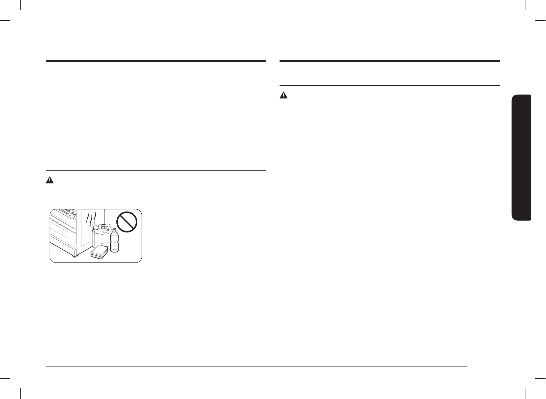
Français 5
Informations de sécurité importantes
SÉCURITÉ EN MATIÈRE DE GAZ
AVERTISSEMENT
Pour réduire les risques d’incendie, d’électrocution, de blessures corporelles et/ou de décès,
respectez les précautions suivantes.
Si vous sentez une odeur de gaz :
• Fermez la vanne et n’utilisez pas la cuisinière.
• N’allumez pas d’allumette, de bougie ou de cigarette.
• N’allumez pas d’appareils électriques ou à gaz.
• N’essayez pas de toucher aux interrupteurs électriques ni de brancher un cordon
d’alimentation dans une prise.
• N’utilisez aucun téléphone dans votre bâtiment.
• Évacuez tous les occupants de la pièce, du bâtiment ou de la zone.
• Appelez immédiatement votre compagnie de gaz depuis le téléphone d’un voisin. Suivez
les instructions de la compagnie de gaz.
• Si votre fournisseur de gaz n’est pas joignable, appelez les pompiers.
Vérication des fuites de gaz
La vérication de la présence de fuites dans l’appareil doit être effectuée selon les instructions
du fabricant. N’utilisez pas de amme pour vérier s’il y a des fuites de gaz. Avec un pinceau,
appliquez un mélange d’eau et de savon tout autour de la surface en question. S’il existe une
fuite de gaz, vous verrez de petites bulles dans le mélange d’eau savonneuse à l’endroit de la
fuite.
• N’utilisez pas de nettoyant pour four ou de doublures de four à l’intérieur ou autour d’une
partie du four.
• Utilisez uniquement des maniques sèches.
• N’utilisez pas la cuisinière pour chauffer des récipients alimentaires non ouverts.
• Ne frappez pas la vitre du four.
• Lorsque vous mettez la cuisinière au rebut, coupez le cordon d’alimentation et retirez la
porte.
• Débranchez ou coupez l’alimentation électrique avant de procéder à l’entretien.
• Veillez à ce que la viande et la volaille soient bien cuites. La viande doit toujours être
cuite à une température interne de 71 °C (160 °F). La volaille doit toujours être cuite à une
température interne de 82 °C (180 °F).
SÉCURITÉ INCENDIE
AVERTISSEMENT
Pour réduire les risques d’incendie, d’électrocution, de blessures corporelles et/ou de décès,
respectez les précautions suivantes.
• Ne rangez pas, ne placez pas et n’utilisez pas
de matériaux inammables ou combustibles
tels que du charbon de bois, du papier, du
plastique, des maniques, du linge de maison,
des rideaux, de l’essence ou d’autres vapeurs
ou liquides inammables à proximité ou à
l’intérieur de la cuisinière.
• Ne portez pas de vêtements amples ou
ottants pendant l’utilisation de la cuisinière.
• Pour éviter l’accumulation de graisse, nettoyez régulièrement les fentes d’aération.
• Ne laissez pas les maniques ou autres matériaux inammables toucher un élément
chauffant. N’utilisez pas de serviette ou tout autre tissu épais comme manique.
• N’utilisez pas d’eau sur un feu de graisse. Pour éteindre un feu de graisse, éteignez la
source de chaleur et étouffez le feu avec un couvercle hermétique ou utilisez un extincteur
polyvalent, chimique sec ou un extincteur à mousse.
• Si un feu de graisse se déclare dans le four, éteignez-le en appuyant sur la touche OFF
(Arrêt). Maintenez la porte du four fermée jusqu’à ce que le feu s’éteigne. Le cas échéant,
utilisez un extincteur polyvalent, chimique sec ou un extincteur à mousse.
• Ne chauffez pas de récipients alimentaires non ouverts — l’accumulation de pression peut
faire éclater le récipient et entraîner des blessures.
DG68-01650A-02_IM_NSY6DG8550SRAA_EN+MES+CFR.indb 5DG68-01650A-02_IM_NSY6DG8550SRAA_EN+MES+CFR.indb 5 2024-12-03 오후 4:13:412024-12-03 오후 4:13:41
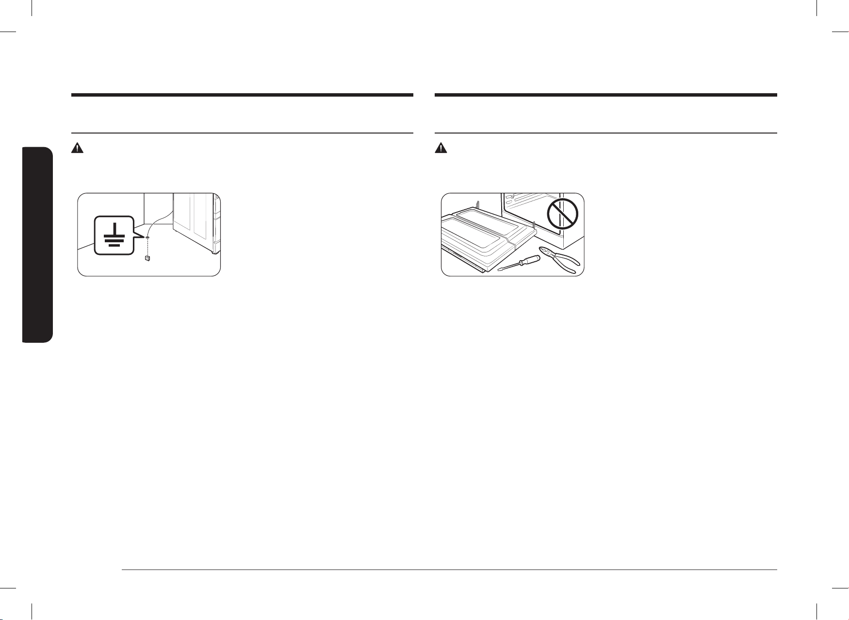
6 Français
Informations de sécurité importantes
Informations de sécurité importantes
SÉCURITÉ DE L’INSTALLATION
AVERTISSEMENT
Pour réduire les risques d’incendie, d’électrocution, de blessures corporelles et/ou de décès,
respectez les précautions suivantes.
• Faites installer votre cuisinière et la mettre
correctement à la terre par un installateur
qualié, conformément aux instructions
d’installation. Tout réglage et entretien doit
être effectué uniquement par des installateurs
ou des techniciens qualiés en matière de
cuisinière à gaz.
• N’essayez pas d’entretenir, de modier ou de remplacer votre cuisinière ou toute partie de
celle-ci, sauf si cela est spéciquement recommandé dans ce manuel. Tout autre entretien
doit être coné à un technicien qualié.
• Utilisez toujours des connecteurs exibles neufs lors de l’installation d’un appareil à gaz.
N’utilisez pas de vieux connecteurs exibles.
• Assurez-vous que le dispositif anti-basculement est correctement installé sur la cuisinière.
Consultez les instructions d’installation pour obtenir des informations supplémentaires.
• En raison de la taille et du poids de la cuisinière, demandez à deux personnes ou plus de la
déplacer.
• Retirez tout le ruban adhésif et les matériaux d’emballage.
• Retirez tous les accessoires de la table de cuisson, du four et/ou du tiroir inférieur.
Les grilles et les plaques sont lourdes. Soyez prudent lorsque vous les manipulez.
• Assurez-vous qu’aucune pièce ne s’est détachée pendant le transport.
• Assurez-vous que votre cuisinière est correctement installée/réglée par un technicien
de service ou un installateur qualié pour le type de gaz (naturel ou GPL) que vous
utiliserez. Pour que votre cuisinière puisse utiliser le gaz de pétrole liquéé, l’installateur
doit remplacer les 5 orices des brûleurs de surface et les 2 orices du four par le jeu
d’orices GPL fourni, et inverser l’adaptateur GPR. Ces réglages doivent être effectués
par un technicien qualié, conformément aux consignes du fabricant et à tous les codes
et exigences de l’autorité compétente. L’agence qualiée qui effectue ce travail assume la
responsabilité de la conversion au gaz.
SÉCURITÉ ÉLECTRIQUE ET MISE À LA TERRE
AVERTISSEMENT
Pour réduire les risques d’incendie, d’électrocution, de blessures corporelles et/ou de décès,
respectez les précautions suivantes.
• Branchez sur une prise à trois broches mise à
la terre.
• Ne retirez pas la broche de terre.
• N’utilisez pas d’adaptateur ou de rallonge.
• N’utilisez pas une prise ou un cordon
d’alimentation endommagés, ni une prise
électrique mal xée.
• Ne modiez pas la che, le cordon ou la prise d’alimentation de quelque façon que ce soit.
• Ne placez pas de fusible dans un circuit neutre ou de mise à la terre.
• Utilisez un circuit électrique dédié de 240 volts, 60 Hz, 40 ampères, CA, avec fusible pour
cette cuisinière. Un fusible à retardement ou un disjoncteur est recommandé. Ne branchez
pas plus d’un appareil sur ce circuit.
• Ne branchez pas le l de terre à des conduites en plastique de plomberie, de gaz ou d’eau
chaude.
• Cette cuisinière doit être mise à la terre. En cas de dysfonctionnement ou de panne, la
mise à la terre réduira le risque de choc électrique en prévoyant un chemin pour le courant
électrique. Cette cuisinière est équipée d’un cordon avec une che de mise à la terre. La
che doit être fermement branchée dans une prise de courant correctement installée et
mise à la terre, conformément aux codes et règlements locaux. Si vous n’êtes pas sûr que
votre prise électrique est correctement mise à la terre, faites-la vérier par un électricien
agréé.
• L’alimentation électrique de la cuisinière doit être conforme aux codes locaux. En l’absence
de codes locaux, il doit être conforme à la norme ANSI/NFPA nº 70 – dernière révision
(pour les É.-U.) ou au Code canadien de l’électricité CSA C22.1 – dernières révisions.
• Il est de la responsabilité personnelle du propriétaire de la cuisinière de fournir le service
électrique correct pour cette cuisinière.
DG68-01650A-02_IM_NSY6DG8550SRAA_EN+MES+CFR.indb 6DG68-01650A-02_IM_NSY6DG8550SRAA_EN+MES+CFR.indb 6 2024-12-03 오후 4:13:422024-12-03 오후 4:13:42
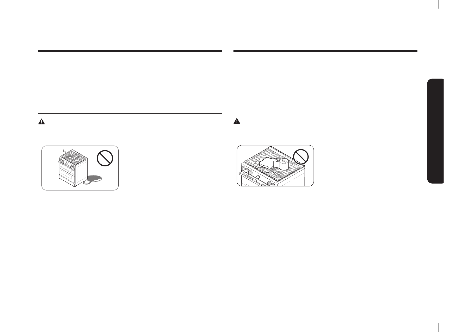
Français 7
Informations de sécurité importantes
• Assurez-vous que les revêtements muraux autour de la cuisinière peuvent résister à la
température maximale générée par la cuisinière qui est de 90 °C (194 °F).
• Il faut éviter de ranger les armoires au-dessus de la surface de la cuisinière. S’il est
nécessaire de disposer des armoires au-dessus de la cuisinière : prévoyez un espace
minimum de 76,2 cm (30 po) entre la surface de cuisson et le bas des armoires ou installez
une hotte qui dépasse horizontalement d’au moins 12,7 cm (5 po) le bas des armoires.
SÉCURITÉ DE LA TABLE DE CUISSON
AVERTISSEMENT
Pour réduire les risques d’incendie, d’électrocution, de blessures corporelles et/ou de décès,
respectez les précautions suivantes.
• Assurez-vous que tous les brûleurs sont
éteints lorsqu’ils ne sont pas utilisés.
• N’utilisez pas de papier aluminium pour
recouvrir les grilles ou toute autre partie de la
table de cuisson.
• Ne laissez pas les brûleurs sans surveillance à
température moyenne ou élevée.
• Avant d’allumer, assurez-vous que tous les chapeaux des brûleurs sont bien en place et que
tous les brûleurs sont parfaitement horizontaux.
• Utilisez toujours la position LITE pour allumer les brûleurs et vériez que ceux-ci se sont
allumés. Si l’allumage échoue, tournez le bouton sur OFF (Arrêt) et attendez que le gaz se
dissipe.
• Lorsque vous réglez un brûleur sur mijotage, ne tournez pas le bouton rapidement.
Vériez que la amme reste allumée.
• Ne placez pas d’autres objets que des ustensiles de cuisson sur la table de cuisson.
• Cette table de cuisson est conçue pour cuisiner avec un wok ou un anneau de wok.
Si les aliments sont enammés, ils ne devraient l’être que sous une hotte de ventilation en
état de fonctionnement.
• Avant de retirer ou de changer d’ustensile de cuisson, éteignez les brûleurs.
• Retirez les aliments et les ustensiles de cuisine immédiatement après la cuisson.
• Avant de retirer une partie du brûleur pour le nettoyer, assurez-vous que la cuisinière est
éteinte et complètement refroidie.
• L’installation de cette cuisinière doit être conforme aux codes locaux ou, en l’absence de
codes locaux, au National Fuel Gas Code, ANSI Z223.1/NFPA.54, dernière édition. Au Canada,
l’installation doit être conforme au Code d’installation du gaz naturel, CAN/CGA-B149.1, ou
au Code d’installation du propane, CAN/CGA-B149.2, et aux codes locaux, le cas échéant.
Cette cuisinière a été certiée par ETL selon la norme ANSI Z21.1, dernière édition, et par
l’Association canadienne du gaz selon la norme CAN/CGA-1.1, dernière édition.
SÉCURITÉ EN MATIÈRE D’EMPLACEMENT
AVERTISSEMENT
Pour réduire les risques d’incendie, d’électrocution, de blessures corporelles et/ou de décès,
respectez les précautions suivantes.
• Cette cuisinière est réservée à un usage
intérieur et domestique. N’installez pas la
cuisinière dans des endroits exposés aux
intempéries et/ou à l’eau.
• N’installez pas la cuisinière dans un endroit
exposé à un fort courant d’air.
• Choisissez un sol horizontal, bien construit et capable de supporter le poids de la
cuisinière. Les revêtements de sol synthétiques, comme le linoléum, doivent résister à des
températures de 82 °C (180 °F) sans rétrécir, se déformer ni se décolorer. N’installez pas
la cuisinière directement sur la moquette intérieure de la cuisine, sauf si une feuille de
contreplaqué de ¼ de pouce ou un isolant comparable est placé entre la cuisinière et la
moquette.
• Choisissez un emplacement où une prise de courant à 3 broches avec mise à la terre est
facilement accessible.
• Si la cuisinière est située près d’une fenêtre, ne suspendez pas de longs rideaux ou des
stores en papier sur cette fenêtre.
• Pour que la cuisinière puisse être ventilée correctement, assurez-vous que les fentes
d’aération de la cuisinière ne sont pas bloqués ou recouverts et qu’il y a sufsamment
d’espace libre en haut, à l’arrière, sur les côtés et sous la cuisinière. Les orices de
ventilation permettent l’échappement nécessaire au bon fonctionnement de l’appareil, à
une combustion correcte et à l’obtention des résultats de cuisson escomptés.
DG68-01650A-02_IM_NSY6DG8550SRAA_EN+MES+CFR.indb 7DG68-01650A-02_IM_NSY6DG8550SRAA_EN+MES+CFR.indb 7 2024-12-03 오후 4:13:422024-12-03 오후 4:13:42
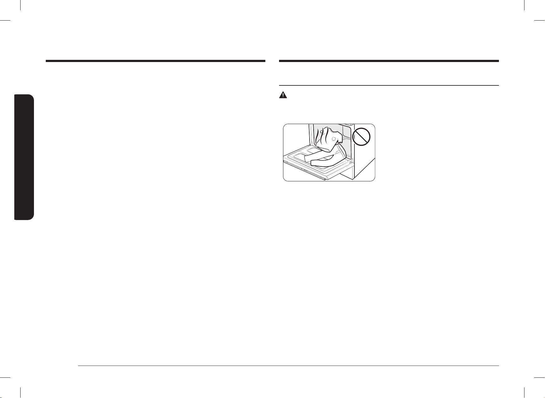
8 Français
Informations de sécurité importantes
Informations de sécurité importantes
SÉCURITÉ DU FOUR
AVERTISSEMENT
Pour réduire les risques d’incendie, d’électrocution, de blessures corporelles et/ou de décès,
respectez les précautions suivantes.
• N’utilisez pas le four à des ns autres que la
cuisson, par exemple le séchage du linge ou le
rangement. Utilisez le four uniquement pour
la cuisson.
• Assurez-vous que la partie intérieure de la
grille de four divisée est bien positionnée
dans la grille extérieure.
• Assurez-vous que les grilles du four sont placées au même niveau de chaque côté.
• N’endommagez pas, ne déplacez pas et ne nettoyez pas le joint de la porte.
• Ne vaporisez pas d’eau sur la vitre du four lorsque celui-ci est allumé ou juste après l’avoir
éteint.
• N’utilisez pas de papier aluminium ou de barquettes en aluminium dans le four. N’utilisez
pas de papier d’aluminium ou de matériau similaire pour couvrir les trous ou les passages
au fond du four ou pour couvrir une grille du four.
• Tenez-vous à l’écart du four lorsque vous ouvrez la porte du four.
• Assurez-vous que le four ne présente aucune accumulation de graisse.
• Lorsque vous repositionnez les grilles du four, assurez-vous que le four est complètement
froid.
• N’utilisez que les ustensiles de cuisson recommandés pour les fours à gaz.
• Pour éviter d’endommager les boutons de commande des brûleurs, faites toujours cuire et/
ou griller les aliments avec la porte du four fermée.
• Gardez les conduits de ventilation du four dégagés. La ventilation du four est située sous
le boîtier de commandes. Cette zone peut devenir chaude durant l’utilisation du four. Ne
jamais obstruer cette ventilation, ni y placer de plastique ou d’éléments sensibles à la
chaleur.
• Suivez les instructions du fabricant en cas d’utilisation de sacs de cuisson ou de rôtissage
dans le four.
• Après nettoyage du diffuseur du brûleur, assurez-vous qu’il est complètement sec avant de
le réassembler.
• Assurez-vous que la marque de l’étincelle sur le diffuseur de brûleur double est placé à côté
de l’électrode lors de l’assemblage.
• Veuillez vous reporter au guide de démarrage pour savoir comment installer les brûleurs.
• Contrôle de la qualité de la amme après avoir installé tous les brûleurs. Veuillez vous
reporter à la page 25.
• Pour éviter tout empoisonnement au monoxyde de carbone, ne versez pas d’eau dans le
puits de la table de cuisson pendant le nettoyage.
• Choisissez des ustensiles de cuisine conçus pour utilisation sur la cuisinière. Utilisez des
ustensiles de cuisson sufsamment grands pour couvrir les grilles des brûleurs. Réglez
les ammes du brûleur de façon à ce qu’elles ne dépassent pas le fond de l’ustensile de
cuisson.
• Pour éviter la décoloration ou la déformation des ustensiles de cuisson ou une intoxication
au monoxyde de carbone, n’utilisez pas d’ustensiles de cuisson beaucoup plus grands que
la grille.
• Assurez-vous que les poignées des ustensiles de cuisson sont tournées vers le côté ou
l’arrière de la table de cuisson, mais pas au-dessus des autres brûleurs de surface.
• Tenez-vous éloigné de la cuisinière pendant la friture.
• Faites toujours chauffer les huiles de friture lentement et surveillez-les pendant qu’elles
chauffent. Si vous faites frire des aliments à feu vif, surveillez attentivement le processus
de cuisson. Si une combinaison de graisses ou d’huiles doit être utilisée pendant la friture,
mélangez-les avant de les mettre sur le feu.
• Utilisez un thermomètre de friteuse chaque fois que c’est possible. Cela évite de surchauffer
la friteuse au-delà du point de fumage.
• Utilisez une quantité minimale d’huile pour la cuisson à la poêle ou la friture. Évitez de
cuire des aliments non décongelés ou des aliments contenant une quantité excessive de
glace.
• Avant de déplacer des ustensiles de cuisine remplis de graisses ou d’huiles,
assurez-vous qu’ils ont complètement refroidi.
• Pour éviter tout risque de débordement après ébullition, laissez toujours les
liquides chauds reposer au moins 20 secondes après avoir éteint le brûleur an
que leur température se stabilise. En cas de brûlure, suivez ces instructions de
premiers secours :
1) Plongez la zone échaudée dans de l’eau fraîche ou tiède pendant au moins 10 minutes.
2) N’appliquez pas de crèmes, d’huiles ou de lotions.
3) Couvrez avec un tissu propre et sec.
DG68-01650A-02_IM_NSY6DG8550SRAA_EN+MES+CFR.indb 8DG68-01650A-02_IM_NSY6DG8550SRAA_EN+MES+CFR.indb 8 2024-12-03 오후 4:13:422024-12-03 오후 4:13:42

Français 9
Informations de sécurité importantes
SÉCURITÉ DU FOUR AUTO-NETTOYANT
AVERTISSEMENT
Pour réduire les risques d’incendie, d’électrocution, de blessures corporelles et/ou de décès,
respectez les précautions suivantes.
• La fonction d’autonettoyage fait fonctionner le
four à des températures sufsamment élevées
pour brûler les salissures alimentaires dans
le four. La cuisinière est extrêmement chaude
pendant un cycle d’autonettoyage. Ne touchez
aucune surface de la cuisinière pendant un
cycle d’autonettoyage.
• Tenez les enfants éloignés du four pendant un cycle d’autonettoyage.
• Avant de lancer un cycle d’autonettoyage, retirez du four toutes les grilles, ustensiles de
cuisson et ustensiles. Seules les grilles du four à revêtement en porcelaine peuvent être
laissées dans le four.
• Avant de lancer un cycle d’autonettoyage, essuyez la graisse et les salissures alimentaires
du four.
• Ne placez pas le tiroir inférieur dans la cavité du four lorsque vous lancez un cycle
d’autonettoyage.
• Lorsque vous ouvrez la porte après un cycle d’autonettoyage, tenez-vous à l’écart du four.
• En cas de dysfonctionnement du cycle d’autonettoyage, éteignez le four, débranchez
l’alimentation électrique et communiquez avec un technicien qualié.
SÉCURITÉ DU TIROIR DE RANGEMENT
AVERTISSEMENT
Pour réduire les risques d’incendie, d’électrocution, de blessures corporelles et/ou de décès,
respectez les précautions suivantes.
• N’utilisez pas le tiroir à des ns autres que la
cuisson, par exemple le séchage du linge ou le
rangement. Utilisez le tiroir uniquement pour
la cuisson.
• Ne touchez pas la surface intérieure du tiroir
ni l’élément chauffant.
• Pour éviter les brûlures dues à la vapeur,
faites attention en ouvrant le tiroir.
• N’utilisez pas de papier d’aluminium pour
tapisser le tiroir.
• N’utilisez pas le tiroir dans le four.
Ne mettez pas le tiroir dans le four pendant
un cycle d’autonettoyage.
• Ne laissez pas de récipients contenant des
graisses dans le tiroir ou à proximité.
DG68-01650A-02_IM_NSY6DG8550SRAA_EN+MES+CFR.indb 9DG68-01650A-02_IM_NSY6DG8550SRAA_EN+MES+CFR.indb 9 2024-12-03 오후 4:13:422024-12-03 오후 4:13:42
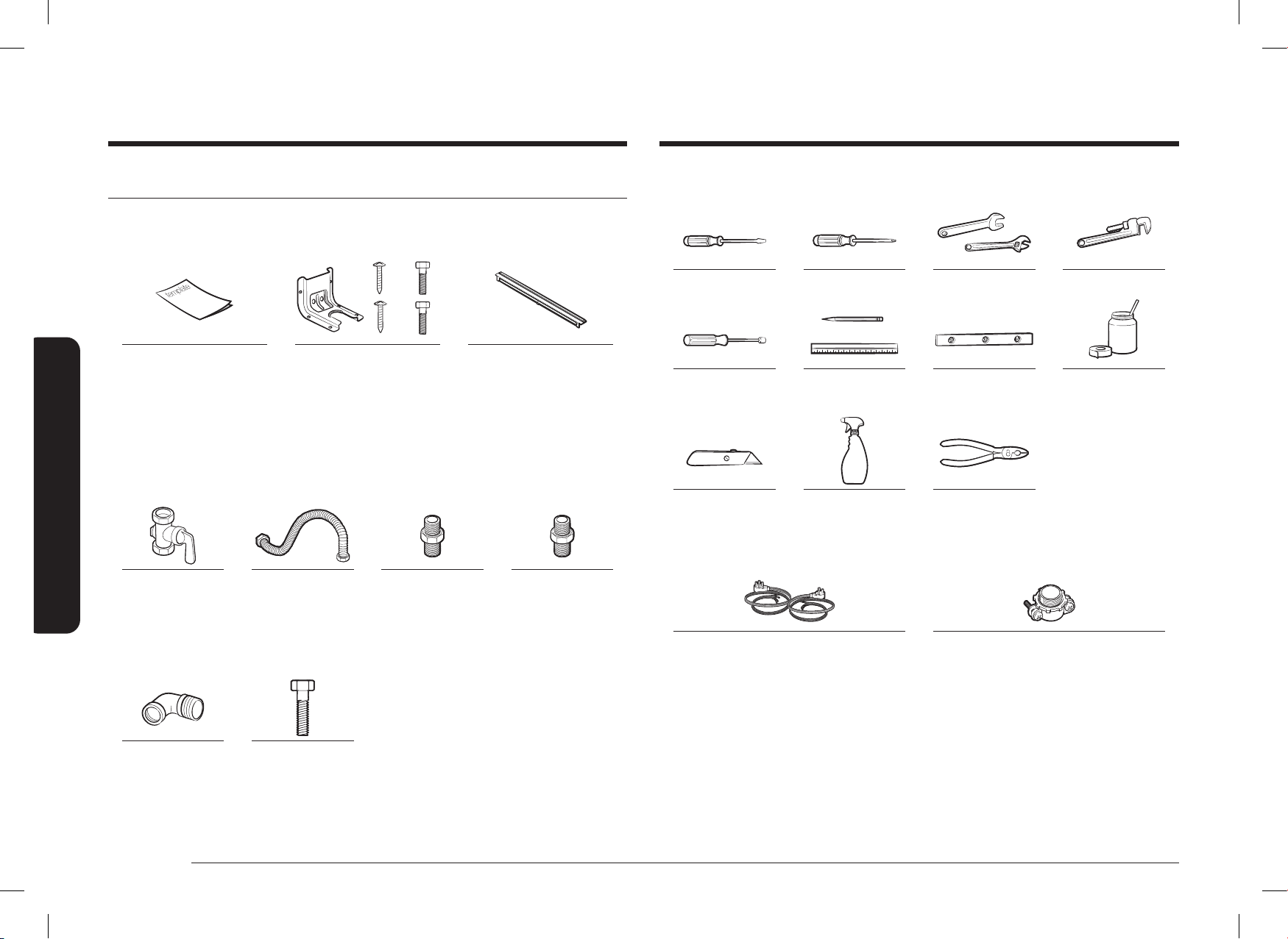
10 Français
Composants de la cuisinière à deux combustibles
Outils nécessaires
Tournevis plat Tournevis cruciforme Clé ouverte ou réglable Clé à tuyau (2)
Tournevis à écrou ¼ po Crayon et règle Niveau Composé pour joints de
tuyaux
Couteau universel Eau savonneuse Pince
Ce qui n’est pas inclus
Cordon à 4 ls ou à 3 ls
(Approuvé UL 40 ou 50 AMP)
*Pour le Canada uniquement
Décharge de traction
(pour l’installation du conduit uniquement)
Composants de la cuisinière à deux combustibles
Contenu de la boîte
Pièces fournies
Patron Support anti-basculement (1)
/ Vis (4)
Kit de ltre (1) et vis (2)
• Assurez-vous que vous avez reçu toutes les pièces fournies indiquées ci-dessus.
• Si votre cuisinière a été endommagée lors de l’expédition ou si vous n’avez pas toutes les
pièces fournies, communiquez avec votre revendeur local.
Pièces nécessaires
Vanne d’arrêt de la
conduite de gaz
Connecteur métallique
exible pour
appareils ménagers
½ po (diamètre
intérieur) x 5 pi
Adaptateur pour
raccord évasé ¾ po
(NPT)
x ½ po
(diamètre intérieur)
Adaptateur pour
raccord évasé
½ po (NPT)
x ½ po
(diamètre intérieur)
Coude à 135 degrés
(en option)
Boulon de calage ou
ancrage à manchon
½ po (DE)
DG68-01650A-02_IM_NSY6DG8550SRAA_EN+MES+CFR.indb 10DG68-01650A-02_IM_NSY6DG8550SRAA_EN+MES+CFR.indb 10 2024-12-03 오후 4:13:442024-12-03 오후 4:13:44
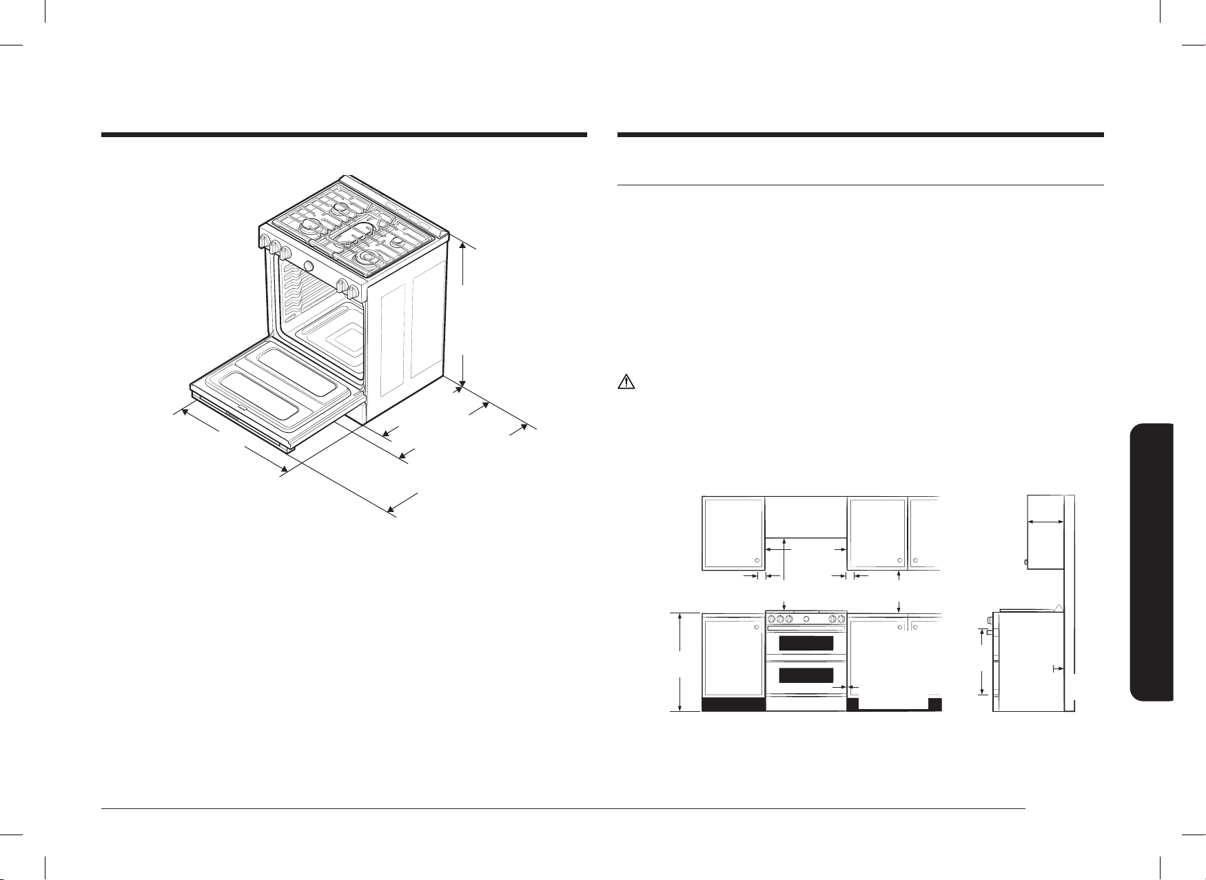
Français 11
Conditions d’installation
36 po
(914,4 mm) min.
36
3
/4 po
(933,5 mm)
max.
29
15
/16 po
(761,0 mm)
26
7
/
16
po
(671,7 mm)
49
1
/
4
po
(1250,3 mm)
Porte complètement
ouverte
28
7
/
16
po
(721,8 mm)
Avec poignée
Conditions d’installation
Exigences relatives à l’emplacement
Dégagements et dimensions
AVANT DE COMMENCER à installer cet appareil, consultez les informations, les dimensions et les
dégagements suivants. Ne placez pas la cuisinière dans un endroit susceptible d’être exposé à
de forts courants d’air. Prévoyez des dégagements adéquats entre la cuisinière et les surfaces
combustibles adjacentes. Ces dimensions doivent être respectées pour une utilisation sans
danger de la cuisinière. L’emplacement de la prise électrique et de la tuyauterie de gaz peut être
ajusté pour respecter les dimensions et les dégagements suivants.
Pour l’installation au Canada, une cuisinière non encastrable ne doit pas être installée à moins de
12 cm (4,7 po) de toute surface adjacente.
MISE EN GARDE
Cette cuisinière a été conçue pour être conforme à la température maximale autorisée pour les
éléments de rangement en bois, soit 90 °C (194 °F). Assurez-vous que le revêtement mural, les
comptoirs et les armoires autour de la cuisinière peuvent résister à la température maximale
générée par la cuisinière qui est de 90 °C (194 °F). Si ce n’est pas le cas, une décoloration, une
délamination ou une fonte peuvent survenir.
33 cm (13 po)
de profondeur
de l’armoire
suspendue
61 cm
(24 po)
Profondeur
de l’armoire
inférieure
10,2 cm
(4 po)
15,2 cm
(6 po)
Dégagement latéral
par rapport au mur
au-dessus de la
surface de cuisson
91,4 cm
(36 po)
76,2 cm
(30 po)
45,7 cm
(18 po)
76,2 cm
(30 po)
0 cm (0 po)
Dégagement sous
le plan de cuisson
ainsi qu’à l’arrière
et sur les côtés de
la cuisinière
Minimum entre la
surface de cuisson
et les armoires
61,5 cm
(24,2 po)
0 cm
(0 po)
DG68-01650A-02_IM_NSY6DG8550SRAA_EN+MES+CFR.indb 11DG68-01650A-02_IM_NSY6DG8550SRAA_EN+MES+CFR.indb 11 2024-12-03 오후 4:13:442024-12-03 오후 4:13:44
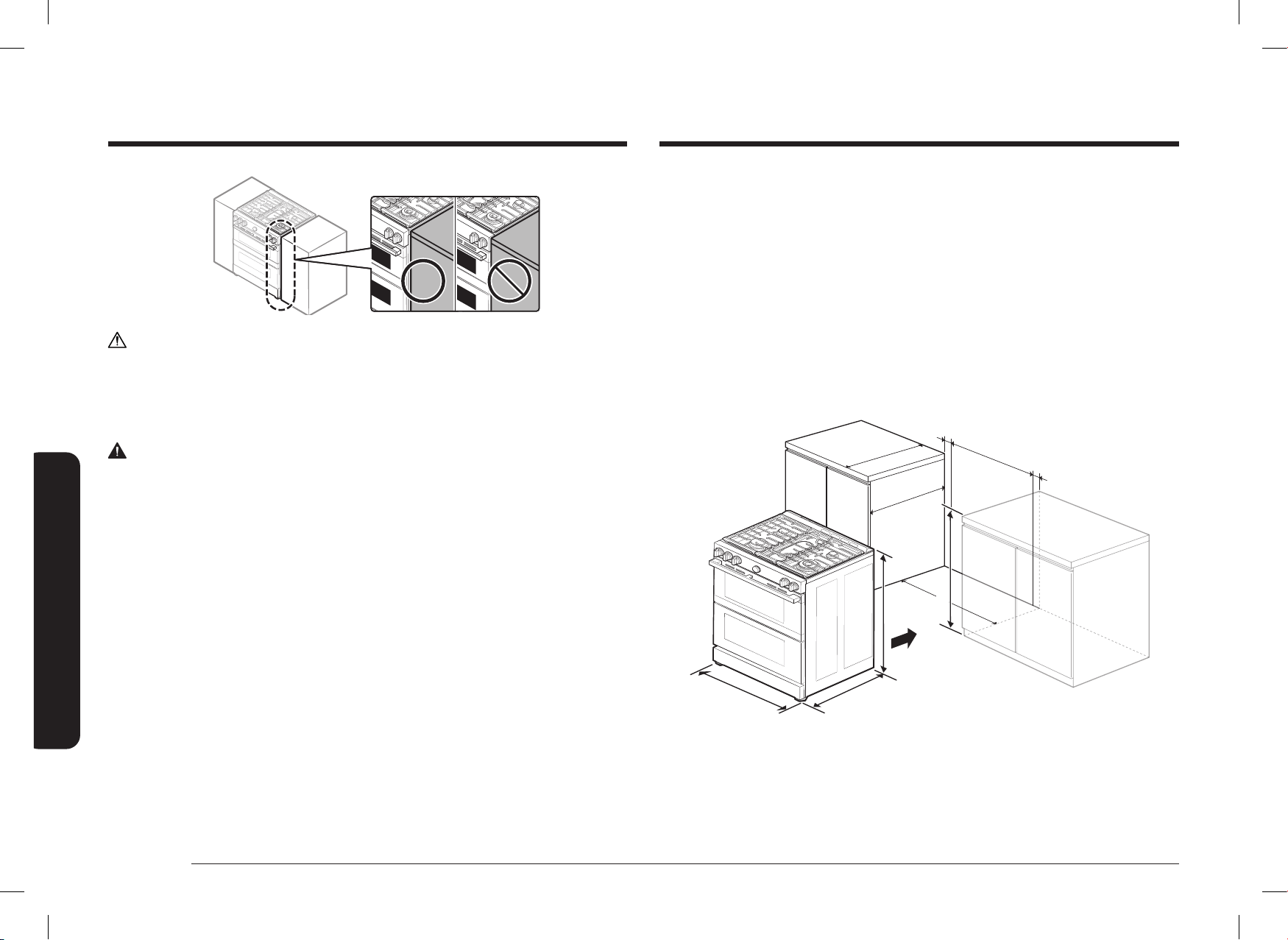
12 Français
Conditions d’installation
Conditions d’installation
ATTENTION
N’installez PAS le four en laissant la porte afeurer l’armoire.
Pour la hotte sur la cuisinière à gaz, veuillez suivre les règlements locaux en matière de gaz.
Dimensions minimales
AVERTISSEMENT
Si des armoires suspendues sont fournies, une hotte doit également être fournie et dépasser
horizontalement d’au moins 12,7 cm (5 po) l’avant des armoires. Elle sera nécessaire pour
dissiper toute accumulation de chaleur dans les armoires suspendues an d’éviter tout risque
de décès, de blessure ou d’incendie. La hotte doit être construite en tôle d’au moins 0,0122 po
d’épaisseur. Installez-la au-dessus de la table de cuisson avec un dégagement d’au moins ¼ po
entre la hotte et le dessous du matériau combustible ou de l’armoire métallique. La hotte doit
être au moins aussi large que l’appareil et centrée sur l’appareil. Le dégagement entre la surface
de cuisson et la surface de la hotte ne doit jamais être inférieur à 24 po.
Exception 1 : L’installation d’un four à micro-ondes ou d’un appareil de cuisson répertorié au-
dessus de la table de cuisson doit être conforme aux installations fournies avec l’appareil.
• Un dégagement minimal de 76,2 cm (30 po) entre le dessus de la surface de cuisson et le
fond d’une armoire en bois ou en métal non protégée; ou en l’absence d’un dégagement
minimal de 76,2 cm (30 po) , un minimum de 61 cm (24 po) peut être utilisé lorsque le fond
de l’armoire en bois ou en métal est protégé par au moins 0,64 cm (¼ po) de panneau de
particules ignifugées recouvert d’au moins une tôle d’acier MSG n
o
28, d’acier inoxydable
de 0,038 cm (0,015 po), d’aluminium de 0,061 cm (0,024 po) ou de cuivre de 0,051 cm
(0,020 po).
• Un dégagement minimal de 45,7 cm (18 po) entre le comptoir et le fond de l’armoire
adjacente.
Exception 2 : Pour l’installation d’un îlot, maintenez un minimum de 2 ½ po entre la découpe et
le bord arrière du comptoir et un minimum de 4 po entre la découpe et les bords latéraux du
comptoir.
IMPORTANT :
Pour éliminer les risques de brûlures ou d’incendie causés par le passage de la main sur les
éléments chauffés, évitez de disposer d’un espace de rangement au-dessus des éléments.
Si vous disposez d’un espace de rangement au-dessus des éléments chauffants, vous pouvez
réduire le risque en installant une hotte qui dépasse horizontalement d’au moins 5 pouces le bas
des armoires.
Guide d’installation
A
36" - 36
36" - 36
3
3
/
/
4
4
"
"
(914.4 mm -
(914.4 mm -
933.5 mm)
933.5 mm)
26
26
7
7
/
/
16
16
"
"
(671.7 mm)
(671.7 mm)
29
29
15
15
/
/
16
16
"
"
(761.0 mm)
(761.0 mm)
25"
25"
3"
3"
24"
24"
24"
24"
3"
3"
35
35
7
7
/
/
8
8
"
"
A : Ouverture de l’armoire 76,2 cm (30 po)
IMPORTANT : Si la hauteur du meuble dépasse 36
3
/4 po, cette cuisinière ne peut pas être
installée sans pièce de support telle que des blocs durs.
DG68-01650A-02_IM_NSY6DG8550SRAA_EN+MES+CFR.indb 12DG68-01650A-02_IM_NSY6DG8550SRAA_EN+MES+CFR.indb 12 2024-12-03 오후 4:13:442024-12-03 오후 4:13:44
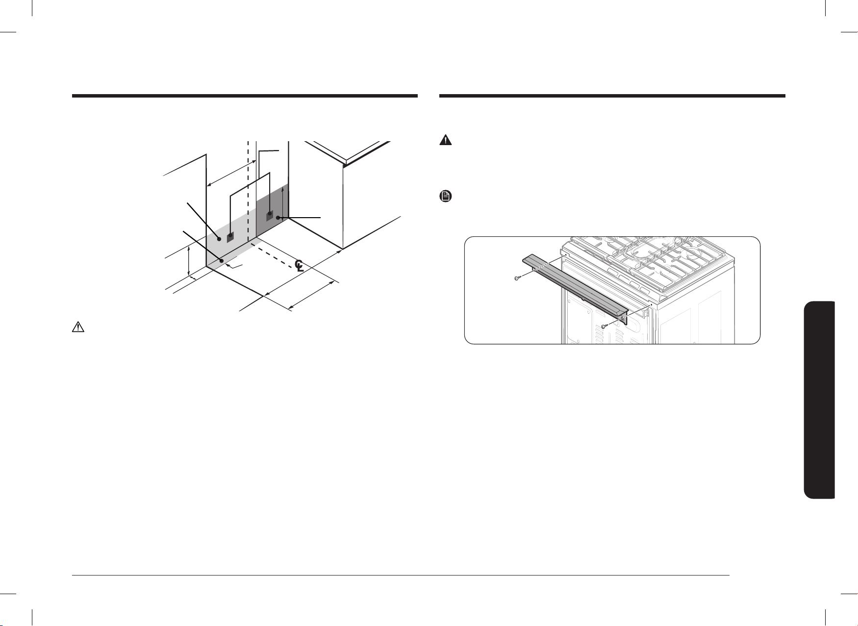
Français 13
Conditions d’installation
Emplacements recommandés pour les conduites de gaz et les prises électriques
(Pour les modèles NSY6
**
8
*
5
***
)
Zone recommandée
Zone recommandée
pour la prise électrique
pour la prise électrique
120V/240V ou
120V/240V ou
120V/208V sur le mur
120V/208V sur le mur
arrière
arrière
Position
Position
recommandée
recommandée
76,2cm (30po)
76,2cm (30po)
Ouverture de
Ouverture de
l’armoire
l’armoire
43,2 cm (17 po)
43,2 cm (17 po)
12 po
12 po
(30,5 cm)
(30,5 cm)
Zone du mur au gaz
Zone du mur au gaz
Zone recommandée pour le
Zone recommandée pour le
raccordement à travers le mur et le
raccordement à travers le mur et le
sol de l’embout de conduite de gaz
sol de l’embout de conduite de gaz
et du robinet d’arrêt.
et du robinet d’arrêt.
Zone du sol
Zone du sol
au gaz
au gaz
43,2 cm
43,2 cm
(17 po)
(17 po)
22,9 cm
22,9 cm
(9 po)
(9 po)
5,1 cm
5,1 cm
(2 po)
(2 po)
ATTENTION
Vous devez utiliser le lot de leur arrière pour installer la cuisinière dans une armoire
autoportante à découpe. Pour plus d’informations, voir « lot de leur arrière en option » comme
indiqué ci-dessous.
Lot de leur arrière en option
AVERTISSEMENT
Utilisé pour combler l’espace entre l’arrière de la cuisinière et le mur. Ajoute une bande de leur
à l’arrière de la cuisinière. Ce lot ne peut être utilisé que lorsque l’ouverture dans le comptoir
dispose d’une profondeur de 25 po.
REMARQUE
Si la profondeur du comptoir est supérieure à 25 po, il existera un espace entre le lot leur et le
mur arrière.
DG68-01650A-02_IM_NSY6DG8550SRAA_EN+MES+CFR.indb 13DG68-01650A-02_IM_NSY6DG8550SRAA_EN+MES+CFR.indb 13 2024-12-03 오후 4:13:452024-12-03 오후 4:13:45
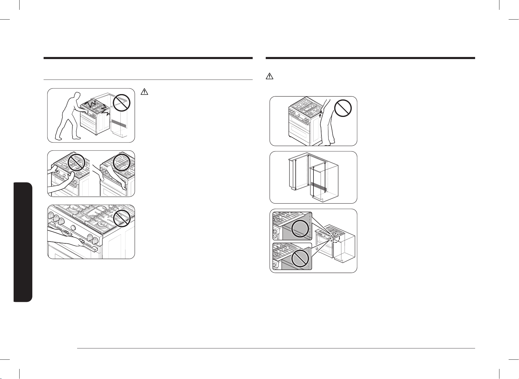
14 Français
Conditions d’installation
Conditions d’installation
ATTENTION
Ne soulevez ni ne manipulez l’unité par le cadre de la table de cuisson.
Fig. 1
Fig. 1
1. Le comptoir autour de la découpe doit être
plat et à niveau (voir la zone hachurée de la
gure 1).
2. Avant d’installer l’unité, mesurez les hauteurs
des deux côtés de l’armoire (C1
~
C4), à l’avant
et à l’arrière (voir gure 1), du sol au haut du
comptoir.
3. Mettez la cuisinière à niveau à l’aide des
quatre pieds de mise à niveau de sorte que la
hauteur entre le sol et le dessous du cadre de
la table de cuisson soit supérieure d’au moins
1/16 po à la mesure la plus haute de l’armoire.
4. Faites glisser l’unité dans l’armoire
(NE PAS EXERCER UNE FORTE PRESSION SUR
L’UNITÉ). Assurez-vous que le centre de l’unité
est aligné avec le centre de la découpe de
l’armoire.
5. Le rebord métallique situé sous chaque
côté de la table de cuisson DOIT être placé
au-dessus du comptoir de l’armoire pour
assurer un soutien adéquat de l’unité. La table
de cuisson ne doit PAS reposer directement
sur le comptoir, sinon elle pourrait être
endommagée, ce qui annulerait la garantie.
Mettez l’unité à niveau le cas échéant.
Pour éviter tout bris
ATTENTION
Veuillez NE PAS exercer une forte pression sur
l’unité lors de l’installation. Ces actions peuvent
causer des dommages à l’unité.
Veuillez NE PAS appuyer sur les boutons des
brûleurs lors de l’installation de la cuisinière.
(Saisissez la zone de la porte L/R pour pousser
l’appareil.)
N’attrapez pas la poignée et n’appuyez pas dessus
lors de l’installation.
DG68-01650A-02_IM_NSY6DG8550SRAA_EN+MES+CFR.indb 14DG68-01650A-02_IM_NSY6DG8550SRAA_EN+MES+CFR.indb 14 2024-12-03 오후 4:13:452024-12-03 오후 4:13:45

Français 15
Conditions d’installation
Exigences particulières en matière de gaz (modèles à gaz vendus dans le
Massachusetts)
EXIGENCES DU COMMONWEALTH DU MASSACHUSETTS :
AVERTISSEMENT
• Il peut y avoir des fuites de gaz dans votre système, entraînant un danger.
- Les fuites de gaz ne sont pas toujours détectables à l’odeur uniquement.
- Les compagnies de gazvous recommandent d’acheter et d’installer un détecteur de gaz
homologué UL. Le détecteur de gaz doit être installé conformément aux instructions
du fabricant.
• La cuisinière doit être installée par un plombier ou un installateur de gaz qualié par l’État
du Massachusetts.
• Une vanne de gaz manuelle à poignée en T DOIT être installée sur la conduite
d’alimentation en gaz de votre cuisinière.
• Si vous utilisez un connecteur de gaz exible pour installer votre cuisinière, il est interdit
de raccorder en série plusieurs conduites de gaz exibles.
Exigences en matière de gaz
Fournissez une alimentation en gaz adéquate
Cette cuisinière est conçue pour fonctionner à une pression de 13 cm (5 po) de colonne d’eau sur
le gaz naturel ou de 25 cm (10 po) de colonne d’eau sur le GPL (propane ou butane).
Assurez-vous que vous alimentez votre cuisinière avec le type de gaz pour lequel elle est
conçue.
N’essayez pas de convertir l’appareil en utilisant un gaz différent de celui indiqué dans ce
manuel sans consulter la compagnie de gaz.
Cette cuisinière est convertible pour une utilisation au gaz naturel ou au gaz propane. Si vous
décidez d’utiliser cette cuisinière au GPL, la conversion doit être effectuée par un installateur
GPL qualié avant toute tentative d’utilisation de la cuisinière.
Pour un bon fonctionnement, la pression du gaz naturel fournie au régulateur doit être comprise
entre 13 cm et 33 cm (5 po et 13 po) de colonne d’eau.
En ce qui concerne le GPL, la pression fournie doit être comprise entre 25 cm et 33 cm (10 po et
13 po) de colonne d’eau.
Lorsque vous contrôlez le bon fonctionnement du régulateur, la pression d’entrée doit être
supérieure d’au moins 2,5 cm (1 po) à la pression de fonctionnement (collecteur) indiquée.
Le régulateur de pression situé à l’entrée du collecteur de la cuisinière doit rester dans la
conduite d’alimentation, que l’on utilise du gaz naturel ou du GPL.
Un connecteur métallique exible utilisé pour raccorder la cuisinière à la conduite d’alimentation
en gaz doit avoir un diamètre intérieur de 1,3 cm (0,5 po) et une longueur de 152 cm (5 pi)
pour faciliter l’installation. Au Canada, les connecteurs exibles doivent être des connecteurs
métalliques à paroi simple et ne pas dépasser 183 cm (6 pi) de longueur.
Ne pliez pas et n’endommagez pas le tube métallique exible lorsque vous déplacez la
cuisinière.
DG68-01650A-02_IM_NSY6DG8550SRAA_EN+MES+CFR.indb 15DG68-01650A-02_IM_NSY6DG8550SRAA_EN+MES+CFR.indb 15 2024-12-03 오후 4:13:452024-12-03 오후 4:13:45

16 Français
Conditions d’installation
Conditions d’installation
Mise à la terre
• Toutes les cuisinières doivent être mises à la terre pour votre sécurité.
• Tous les modèles à gaz sont équipés d’un cordon d’alimentation avec un conducteur de
mise à la terre et une che de mise à la terre.
• Ne pas utiliser de che d’alimentation endommagée ou une prise murale mal xée.
• N’utilisez pas de rallonge ou d’adaptateur pour cet appareil.
• Ne coupez pas, ne modiez pas, n’enlevez pas ou ne défaites en aucun cas la (troisième)
broche de mise à la terre du cordon d’alimentation. Si la che et la prise ne correspondent
pas ou si vous avez un doute, demandez à un électricien qualié d’installer la prise
appropriée.
Le client doit faire vérier la prise murale et le circuit par un électricien qualié an de
s’assurer que la prise est correctement mise à la terre.
Les disjoncteurs de fuite à la terre (GFCI) ne sont ni nécessaires ni recommandés pour les
prises des cuisinières à gaz.
• NE JAMAIS brancher le l de terre sur des conduites de plomberie en plastique, des
conduites de gaz ou des conduites d’eau.
ATTENTION
Le non-respect de ces instructions peut entraîner la mort, un incendie ou un choc électrique.
Conditions d’installation supplémentaires pour les maisons mobiles
L’installation d’appareils conçus pour les maisons mobiles doit être conforme à la norme sur la
construction et la sécurité des maisons mobiles (Manufactured Home Construction and Safety
Standard), article 24 CFR (Code of Federal Regulations), partie 3280 (anciennement la norme
fédérale sur la construction et la sécurité des maisons mobiles, article 24, HUD (Département du
Logement et du Développement urbain), partie 280) ou, lorsque cette norme n’est pas applicable,
à la norme sur les installations de maisons mobiles (Manufactured-Home Installations), dernière
édition (sites, communautés et installations de maisons mobiles), ANSI A225.1, dernière édition,
ou aux codes locaux. Au Canada, l’installation des maisons mobiles doit être conforme au Code
d’installation des maisons mobiles CAN/CSA Z240/MH en vigueur.
Exigences électriques
AVERTISSEMENT
Pour réduire les risques d’incendie, de décharge électrique ou de blessures :
Toutes les cuisinières
• N’utilisez pas de rallonge ou de che d’adaptation pour cette cuisinière.
• Cette cuisinière doit être correctement mise à la terre.
• En cas de doute, consultez un électricien qualié pour savoir si votre cuisinière est
correctement mise à la terre.
• Ne modiez pas la che fournie avec votre cuisinière — si elle ne convient pas à la prise,
faites installer une prise appropriée par un électricien qualié.
• Tout le câblage et la mise à la terre doivent être effectués conformément aux codes locaux
ou, à défaut, au Code national de l’électricité, ANSI/NFPA No 70 — dernière révision (pour
les États-Unis) ou au Code canadien de l’électricité CSA C22.1 — dernières révisions et aux
codes et règlements locaux.
• Le schéma de câblage est situé à l’arrière de la cuisinière. (à l’intérieur de la protection
arrière du câblage)
• Cette cuisinière est équipée d’un système d’allumage électronique qui ne fonctionnera pas
si elle est branchée dans une prise qui n’est pas correctement polarisée.
Modèles à gaz
• Tous les modèles à gaz au Canada sont équipés d’un cordon d’alimentation avec un
conducteur et une che de mise à la terre.
(Le cordon d’alimentation n’est pas fourni dans le modèle américain.)
• Un service électrique approuvé de 240 V, 60 Hz, CA, avec un disjoncteur de 40 A ou un
fusible à retardement est nécessaire pour tous les modèles américains et canadiens.
• Vériez la présence d’une décharge de traction de 1,9 cm (¾ po) homologuée UL à l’endroit
où le cordon d’alimentation sort de l’armoire de la cuisinière.
• Ne réutilisez pas un cordon d’alimentation électrique provenant d’une ancienne cuisinière
ou d’un autre appareil.
• Le câblage d’alimentation électrique du cordon d’alimentation doit être retenu au niveau
de l’armoire de la cuisinière à l’aide d’un dispositif de décharge de traction approprié
homologué UL.
• Un fusible à retardement ou un disjoncteur est également recommandé.
DG68-01650A-02_IM_NSY6DG8550SRAA_EN+MES+CFR.indb 16DG68-01650A-02_IM_NSY6DG8550SRAA_EN+MES+CFR.indb 16 2024-12-03 오후 4:13:452024-12-03 오후 4:13:45

Français 17
Instructions d’installation
Instructions d’installation
Cet appareil doit être alimenté avec la tension et
la fréquence appropriées, et raccordé à un circuit
de dérivation individuel correctement mis à la
terre, protégé par un disjoncteur ou un fusible dont
l’intensité de courant est indiquée sur la plaque
signalétique. La plaque signalétique est située au-
dessus du tiroir sur le cadre du four.
Nous vous recommandons de faire raccorder le
câblage électrique et le branchement de votre
cuisinière par un électricien qualié. Après
l’installation, demandez à l’électricien de vous
montrer où se trouve le sectionneur principal de la
cuisinière.
Vériez auprès des services publics locaux les
codes électriques en vigueur dans votre région.
Si vous ne câblez pas votre four conformément
aux codes en vigueur, vous risquez de créer une
situation dangereuse. S’il n’existe aucun code
local, votre cuisinière doit être câblée et munie
de fusibles conformément aux exigences du Code
national de l’électricité, ANSI/NFPA n° 70 – dernière
édition. Vous pouvez en obtenir une copie en
écrivant à :
National Fire Protection Association, Batterymarch
Park, Quincy, MA 02269
Depuis le 1
er
janvier 1996, le Code national de l’électricité exige que les nouvelles constructions
(non existantes) utilisent un branchement à 4 conducteurs pour une cuisinière électrique.
Lorsque vous installez une cuisinière électrique dans une nouvelle construction, suivez les
étapes 2 et 3 pour un branchement à 4 ls.
Vous devez utiliser un courant alternatif monophasé à 3 ou 4 ls. Système électrique de
208 Y/120 V ou 240/120 V, 60 Hz.
Si le service électrique fourni ne répond pas aux spécications ci-dessus, demandez à un
électricien agréé d’installer une prise homologuée.
Installation de votre cuisinière à deux combustibles
IMPORTANT :
Veuillez lire complètement et attentivement les instructions suivantes, ainsi que la section
Consignes de sécurité importantes au début de ce manuel, AVANT d’installer et/ou d’utiliser la
cuisinière à gaz. Une mauvaise installation, un mauvais réglage, un entretien ou une réparation
inadéquats peuvent provoquer des blessures ou des dégâts matériels.
REMARQUE
Pour commander des pièces ou des accessoires,
communiquez avec votre revendeur local ou
reportez-vous à la dernière page.
REMARQUE
Pour garantir une installation correcte, nous vous
recommandons vivement de faire appel à un
installateur professionnel.
Étape 1 : Déballez la cuisinière
Retirez tous les matériaux d’emballage. Si vous ne retirez pas les matériaux d’emballage, vous
risquez d’endommager l’appareil.
Faites l’inventaire de toutes les pièces lâches en vous reportant à la liste des pièces fournies à la
page 10.
Vériez si l’appareil n’a pas été endommagé lors du transport et/ou s’il manque des pièces. Tout
dommage et/ou pièce manquante doit être signalé à votre revendeur local.
Étape 2 : Satisfaire aux exigences de branchement électrique
ATTENTION
Pour votre sécurité, n’utilisez pas de rallonge pour cet appareil. Retirez le fusible de la maison
ou ouvrez le disjoncteur avant de commencer l’installation
DG68-01650A-02_IM_NSY6DG8550SRAA_EN+MES+CFR.indb 17DG68-01650A-02_IM_NSY6DG8550SRAA_EN+MES+CFR.indb 17 2024-12-03 오후 4:13:452024-12-03 오후 4:13:45

18 Français
Instructions d’installation
Instructions d’installation
Étape 3 : Accès au raccord du cordon d’alimentation
Retirez le panneau d’accès situé à l’arrière et desserrez la vis à l’aide d’un tournevis. Le bornier
sera alors accessible.
Panneau d’accès
Bornier
Puissance nominale indiquée du kit de cordon d’alimentation
Puissance nominale de la cuisinière,
en watts
Puissance nominale
indiquée du
kit de cordon
d’alimentation, en
ampères
Diamètre (pouces) de
l’ouverture de branchement de
la cuisinière
120/240 volts
3 ls
120/208 volts
3 ls
Cordon
d’alimentation
Conduit
8750 à 16500 7801 à 12500 40 ou 50 A 1 ⅜ po 1 ⅛ po
Utilisez uniquement un cordon de cuisinière à 3 ou 4 conducteurs homologué UL. Ces cordons
peuvent être équipés de bornes à anneau sur le l et d’un dispositif de décharge de traction.
Un cordon de cuisinière de 40 A avec une plage de tension minimale de 125/250 V est
nécessaire.
Un cordon de cuisinière de 50 A n’est pas recommandé, mais s’il est utilisé, il doit être marqué
pour être utilisé avec des ouvertures de branchement d’un diamètre nominal de 1 ⅜ po. Il faut
veiller à centrer le câble et la décharge de traction dans le trou défonçable pour éviter que le
bord n’endommage le câble.
• Étant donné que les bornes de la cuisinière ne sont pas accessibles une fois la cuisinière en
place, il faut utiliser un conduit ou un cordon d’alimentation exible.
REMARQUE
• Si vous utilisez un conduit, passez à l’étape 5 des pages 20
~
21.
• Si le branchement d’alimentation est mal xé, le message suivant s’afche à l’écran.
- LCD, PMOLED : Échec d’installation de ls
- DEL : mauvaise conduite
• Rebranchez correctement l’alimentation et le message disparaît.
TOUTES LES NOUVELLES CONSTRUCTIONS DE CIRCUITS DE DÉRIVATION, LES
MAISONS MOBILES, LES VÉHICULES DE LOISIRS ET LES INSTALLATIONS POUR
LESQUELLES LES CODES LOCAUX N’AUTORISENT PAS LA MISE À LA TERRE
PAR LE NEUTRE, NÉCESSITENT UN CORDON DE CUISINIÈRE À 4 CONDUCTEURS
HOMOLOGUÉ UL.
DG68-01650A-02_IM_NSY6DG8550SRAA_EN+MES+CFR.indb 18DG68-01650A-02_IM_NSY6DG8550SRAA_EN+MES+CFR.indb 18 2024-12-03 오후 4:13:462024-12-03 오후 4:13:46

Français 19
Instructions d’installation
Conducteur
de terre
Borne
neutre
Noir
Blanc
Rouge
Noir
Blanc
Rouge
1. Retirez les 3 vis de la borne inférieure du
bornier.
2. Insérez les trois 3 vis de borne à travers
chaque anneau de borne du cordon
d’alimentation et dans les bornes inférieures
du bornier. Assurez-vous que le l central
(blanc/neutre) est connecté à la position
centrale inférieure du bornier.
3. Serrez fermement les vis dans le bornier.
NE retirez PAS le raccord du conducteur de
terre.
4. Passez à l’étape 6 de la page 22 et poursuivez
l’installation.
Étape 4 : Installation du cordon d’alimentation
Pour l’installation du cordon d’alimentation, accrochez la décharge de traction sur le trou
du cordon d’alimentation (1 ⅜ po) situé sous l’arrière du corps du tiroir. Insérez le cordon
d’alimentation à travers la décharge de traction et serrez le dispositif.
Décharge de traction
Cordon
d’alimentation
Plaque de raccordement
des conduits
• Vous devez installer le cordon d’alimentation avec une décharge de traction.
• Fixez la décharge de traction à l’ouverture de 1 ⅜ po dans la plaque de raccordement de
conduit.
Installation d’un cordon d’alimentation à 3 ls
AVERTISSEMENT
Le l neutre ou de terre du cordon d’alimentation doit être branché à la borne neutre située au
centre du bornier. Les ls d’alimentation doivent être branchés aux bornes inférieure gauche et
inférieure droite du bornier.
DG68-01650A-02_IM_NSY6DG8550SRAA_EN+MES+CFR.indb 19DG68-01650A-02_IM_NSY6DG8550SRAA_EN+MES+CFR.indb 19 2024-12-03 오후 4:13:462024-12-03 오후 4:13:46

20 Français
Instructions d’installation
Instructions d’installation
Étape 5 : Installation du conduit
Retirez la plaque de raccordement de conduit à l’arrière du corps du tiroir et faites-la pivoter
comme indiqué ci-dessous.
Le trou de conduit (1 ⅛ po) doit être utilisé.
1 ⅛ po 1 ⅜ po
1 ⅛ po1 ⅜ po
1. Préparez le cordon de conduit illustré à la gure 1.
2. Installez le cordon de conduit comme illustré à la gure 2.
Plaque de raccordement des conduits
Décharge de traction
Anneau
Corps
Figure 2Figure 2
1 po
3½ po
⅜ po 1 po
3½ po
3 ls3 ls 4 ls4 ls
Surface défonçable
Figure 1Figure 1
⅜ po
Pour ce qui est des installations de conduit, insérez la décharge de traction (non fournie) dans
le trou de conduit (1 ⅛ po). Enlez ensuite le cordon de conduit dans le corps de la décharge de
traction et xez l’anneau. Réinstallez le support.
Installation d’un cordon d’alimentation à 4 ls
AVERTISSEMENT
Le l neutre du circuit d’alimentation doit être branché à la borne neutre située dans le centre
inférieur du bornier. Les ls d’alimentation doivent être branchés aux bornes inférieure gauche
et inférieure droite du bornier. Le quatrième l de mise à la terre doit être branché au cadre de
la cuisinière à l’aide de la plaque de terre et de la vis de terre.
Conducteur de
terre
Plaque de terre
Vis de
terre
Borne neutre
Fil de terre
(vert)
Blanc
Noir
Rouge
Noir
Blanc
Rouge
1. Retirez les 3 vis de la borne inférieure du
bornier. Retirez la vis de terre et la plaque de
mise à la terre et conservez-les.
2. Coupez et jetez le conducteur de terre.
Ne jetez aucune vis.
3. Insérez la vis de terre dans l’anneau de la
borne du l de terre du cordon d’alimentation,
à travers la plaque de terre et dans le cadre de
la cuisinière.
4. Insérez les 3 vis de borne (retirées
précédemment) dans chaque anneau de
borne du cordon d’alimentation et dans les
bornes inférieures du bornier. Assurez-vous
que le l central (blanc/neutre) est connecté
à la position centrale inférieure du bornier.
Serrez fermement les vis dans le bornier.
5. Passez à l’étape 6 de la page 22 et poursuivez
l’installation.
DG68-01650A-02_IM_NSY6DG8550SRAA_EN+MES+CFR.indb 20DG68-01650A-02_IM_NSY6DG8550SRAA_EN+MES+CFR.indb 20 2024-12-03 오후 4:13:472024-12-03 오후 4:13:47

Français 21
Instructions d’installation
Installation d’un conduit à 4 ls
• Un l de construction en aluminium peut être utilisé, toutefois celui-ci doit être calibré
selon l’ampérage et la tension appropriés pour effectuer le branchement. Branchez les ls
conformément à l’étape 4 en fonction du nombre de ls.
• Le l utilisé, l’emplacement et le boîtier des épissures, etc., doivent être conformes aux
bonnes pratiques de câblage et aux codes locaux.
Conducteur de
terre
Plaque de terre
Blanc
Noir
Rouge
Borne
neutre
Fil de terre
(vert)
Pointes
des ls
Blanc
Noir
Rouge
1. Desserrez les 3 vis de la borne inférieure du
bornier. Retirez la vis de terre et la plaque de
mise à la terre et conservez-les.
2. Coupez et jetez le conducteur de terre. Ne
jetez aucune vis.
3. Insérez la pointe du l nu de terre entre le
cadre de la cuisinière et la plaque de terre
(retirée précédemment) et xez-la en place
avec la vis de terre (retirée précédemment).
4. Insérez la pointe du l nu (blanc/neutre) dans
l’ouverture du bornier central inférieur.
5. Insérez les deux pointes latérales du l nu
dans les ouvertures du bornier inférieur
gauche et du bornier inférieur droit.
6. Serrez les vis jusqu’à ce que le l soit
fermement xé (35 à 50 pouces-livres).
Ne serrez pas trop les vis, car cela pourrait
endommager les ls.
7. Passez à l’étape 6 et poursuivez l’installation.
Installation d’un conduit à 3 ls
• Un l de construction en aluminium peut être utilisé, toutefois celui-ci doit être calibré
selon l’ampérage et la tension appropriés pour effectuer le branchement. Branchez les ls
conformément à l’étape 4 en fonction du nombre de ls.
• Le l utilisé, l’emplacement et le boîtier des épissures, etc., doivent être conformes aux
bonnes pratiques de câblage et aux codes locaux.
Blanc
Noir
Rouge
Conducteur
de terre
Borne
neutre
Pointes des ls
Rouge
Blanc
Noir
1. Desserrez les 3 vis de la borne inférieure du
bornier.
2. Insérez la pointe du l nu central (blanc/
neutre) dans l’ouverture du bornier central
inférieur. Sur certains modèles, le l devra
être inséré dans l’ouverture du conducteur de
terre, puis dans l’ouverture du bornier central
inférieur.
3. Insérez les deux pointes latérales du l nu
dans les ouvertures du bornier inférieur
gauche et du bornier inférieur droit.
4. Serrez les vis jusqu’à ce que le l soit
fermement xé (35 à 50 pouces-livres).
Ne serrez pas trop les vis, car cela pourrait
endommager les ls.
5. Passez à l’étape 6 de la page 22 et poursuivez
l’installation.
DG68-01650A-02_IM_NSY6DG8550SRAA_EN+MES+CFR.indb 21DG68-01650A-02_IM_NSY6DG8550SRAA_EN+MES+CFR.indb 21 2024-12-03 오후 4:13:472024-12-03 오후 4:13:47
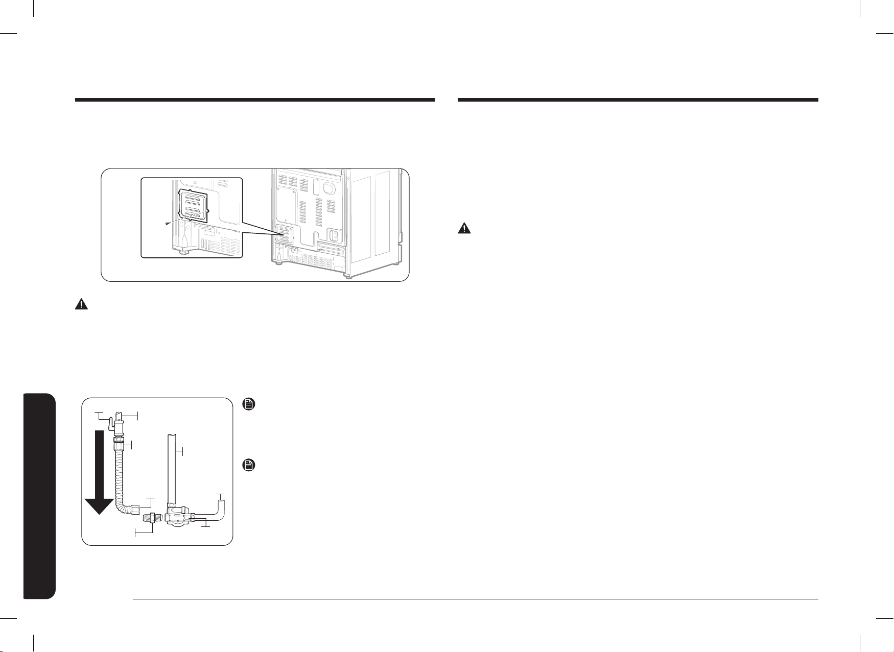
22 Français
Instructions d’installation
Instructions d’installation
Étape 7 : Branchement de la cuisinière à l’alimentation en gaz
Fermez la vanne principale d’alimentation en gaz avant de débrancher l’ancienne cuisinière et
laissez-la fermée jusqu’à ce que le nouveau branchement soit terminé. N’oubliez pas de rallumer
la veilleuse des autres appareils à gaz lorsque vous rallumez le gaz.
Étant donné que la tuyauterie rigide limite le mouvement de la cuisinière, il est recommandé
d’utiliser un raccord métallique exible homologué CSA International, à moins que les codes
locaux n’exigent un raccord rigide.
AVERTISSEMENT
• Le non-respect des informations contenues dans ce manuel peut provoquer un incendie
ou une explosion peut se produire et entraîner la mort, des blessures ou des dommages
matériels.
- Veillez à ne pas conserver ni utiliser d’essence ou d’autres vapeurs ou liquides
inammables près de cet appareil ou de tout autre appareil.
- QUE FAIRE SI VOUS SENTEZ UNE ODEUR DE GAZ :
• N’allumez PAS d’allumette, de bougie ou de cigarette.
• N’essayez PAS de mettre un appareil en marche.
• N’essayez PAS de toucher aux interrupteurs électriques.
• N’utilisez aucun téléphone dans votre bâtiment.
• Libérez la pièce, le bâtiment ou la zone de tous les occupants.
• Appelez immédiatement votre compagnie de gaz depuis le téléphone d’un voisin. Suivez les
instructions de la compagnie de gaz.
• Si votre fournisseur de gaz n’est pas joignable, appelez les pompiers.
- L’installation et l’entretien doivent être effectués par un installateur qualié, un
organisme de service ou la compagnie de gaz.
Étape 6 : Remplacement du panneau d’accès
Remettez le panneau d’accès en place à l’arrière de la cuisinière. Pour remplacer la protection
des ls, insérez les doubles saillies dans les poches situées sous l’ouverture et serrez la vis.
AVERTISSEMENT
Ne dépassez pas un couple de serrage de 25 pi/lb lorsque vous effectuez les raccordements de
la conduite de gaz. Un serrage excessif peut ssurer le régulateur de pression et provoquer une
fuite de gaz.
Raccordement du connecteur exible
Installateur : Indiquer au consommateur l’emplacement de la vanne d’arrêt du gaz.
Adaptateur
Connecteur
exible (6 pi
max.)
Adaptateur
Vanne d’arrêt de gaz
Tuyau de gaz de 0,5 po ou 0,75 po
Conduite tubulaire
vers la vanne
de contrôle du
brûleur du four
Débit de gaz dans la cuisinière
Régulateur
de pression
Conduite tubulaire
vers le collecteur
de commande de
la cuisinière
REMARQUE
Si votre région exige un raccordement à un tuyau
rigide, communiquez avec un installateur qualié,
un organisme de service ou une compagnie de gaz.
REMARQUE
La vanne d’arrêt de gaz doit être installé dans
un endroit accessible de la tuyauterie de gaz, à
l’extérieur de l’appareil, an d’ouvrir ou de fermer
le gaz à l’appareil.
DG68-01650A-02_IM_NSY6DG8550SRAA_EN+MES+CFR.indb 22DG68-01650A-02_IM_NSY6DG8550SRAA_EN+MES+CFR.indb 22 2024-12-03 오후 4:13:482024-12-03 오후 4:13:48
Français 23
Instructions d’installation
Étape 8 : Conversion au GPL (en option)
Toutes les nouvelles cuisinières à gaz sortent réglées de l’usine pour fonctionner au gaz naturel.
Toute cuisinière à gaz Samsung peut être convertie pour utiliser du gaz propane. Reportez-vous
à la page 57 du manuel d’utilisation pour communiquer avec un technicien de service qualié.
Le processus de conversion ne doit être effectué que par un installateur GPL qualié. Les
instructions de conversion et les orices de PL sont fournis avec le kit de conversion PL. La
conversion au GPL nécessite le remplacement de tous les orices des brûleurs (5 brûleurs de
surface).
De plus, la buse du régulateur de pression de gaz doit être inversée. Tous les orices remplacés
doivent être laissés au consommateur, y compris les instructions ainsi que les dimensions et
l’indication des orices.
Vérication de la qualité de la amme de tous les brûleurs après la conversion au gaz de pétrole
liquéé.
N’utilisez jamais un ancien raccord lors de l’installation d’une nouvelle cuisinière. Si vous utilisez
la méthode de raccordement rigide, vous devez aligner soigneusement le tuyau; la cuisinière ne
peut plus être déplacée une fois le raccordement effectué.
Pour éviter les fuites de gaz, appliquer de la pâte à joint ou envelopper de téon tous les
letages mâles (externes) des tuyaux.
1. Installez une vanne d’arrêt manuelle sur la conduite de gaz, à un endroit facilement
accessible à l’extérieur de la cuisinière.
Assurez-vous que toute personne utilisant la cuisinière sait où et comment couper
l’alimentation en gaz de la cuisinière.
2. Installez l’adaptateur pour raccord évasé mâle de 1,3 cm (0,5 po) sur le let interne NPT
de 1,3 cm (0,5 po) à l’entrée du régulateur. Utilisez une clé de secours sur le raccord du
régulateur pour éviter de l’endommager.
Lorsque vous installez la cuisinière par l’avant, retirez le coude à 90 ° pour faciliter
l’installation.
3. Installez le raccord union mâle évasé de 1,3 cm (0,5 po) ou 1,9 cm (0,75 po) sur le let
interne NPT de la vanne de coupure de gaz manuelle, en prenant soin de la soutenir an de
l’empêcher de tourner.
4. Branchez le connecteur métallique exible de l’appareil à l’adaptateur de la cuisinière.
Positionnez la cuisinière pour permettre le raccordement à la vanne d’arrêt.
5. Une fois tous les raccordements effectués, assurez-vous que toutes les commandes de la
cuisinière sont en position off (arrêt) et ouvrez la vanne principale d’alimentation en gaz.
Utilisez un détecteur de fuites liquides à tous les joints et raccords pour vérier l’absence
de fuites dans le système.
AVERTISSEMENT
Pour éviter tout risque de mort, de blessure, d’explosion et/ou d’incendie, N’utilisez PAS de
amme pour vérier la présence de fuites de gaz.
Si vous utilisez des pressions d’essai supérieures à ½ psig pour tester la pression du système
d’alimentation en gaz de la résidence, débranchez la cuisinière et la vanne d’arrêt individuelle de
la tuyauterie d’alimentation en gaz. Si vous utilisez des pressions d’essai inférieures ou égales à
½ psig pour tester le système d’alimentation en gaz, isolez simplement la cuisinière du système
d’alimentation en gaz en fermant la vanne d’arrêt individuelle.
DG68-01650A-02_IM_NSY6DG8550SRAA_EN+MES+CFR.indb 23DG68-01650A-02_IM_NSY6DG8550SRAA_EN+MES+CFR.indb 23 2024-12-03 오후 4:13:482024-12-03 오후 4:13:48
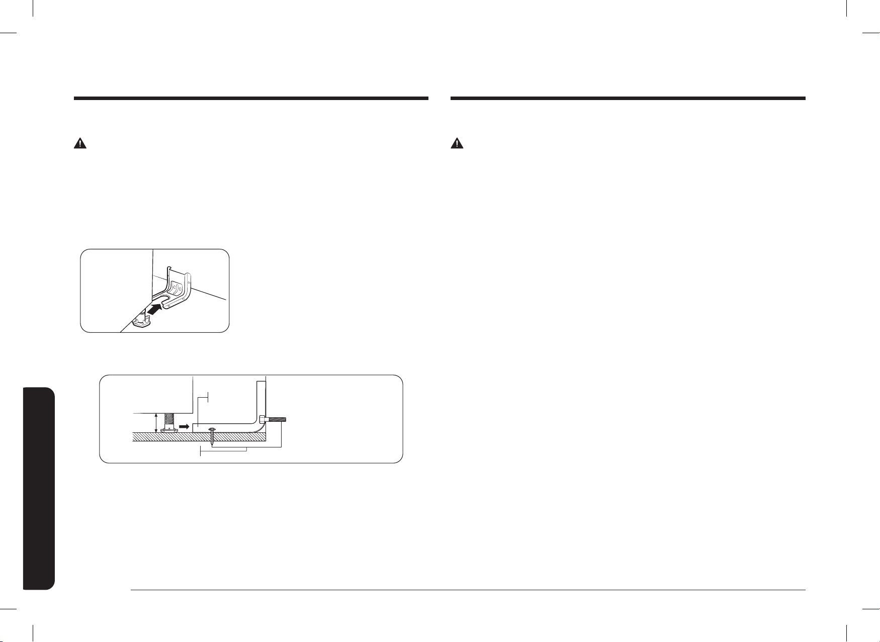
24 Français
Instructions d’installation
Instructions d’installation
Étape 10 : Branchement et pose
AVERTISSEMENT
AVANT L’UTILISATION OU LE TEST, respectez les exigences de mise à la terre indiquées aux
pages 15
~
16 de ce manuel. Tout branchement non conforme de la che de mise à la terre peut
entraîner un risque d’électrocution.
• Toute cuisinière à deux combustibles est équipée d’un cordon d’alimentation. Le cordon
d’alimentation est branché à l’arrière de la cuisinière. Veuillez consulter « Exigences
électriques » aux pages 15
~
16.
• Le système électrique, y compris le cordon d’alimentation, est préinstallé et précâblé en
usine. Toute modication d’une partie de ce système peut entraîner un court-circuit ou une
surcharge.
1. Brancher le cordon d’alimentation. Assurez-vous que la prise est conforme aux codes
électriques locaux ou nationaux, comme indiqué aux pages 15
~
16.
2. Faites glisser la cuisinière dans son emplacement.
3. Vériez la conduite d’alimentation en gaz pour vous assurer qu’elle n’a pas été
endommagée et qu’elle est restée branchée pendant le positionnement.
4. Vériez si le pied arrière de la cuisinière a glissé dans le support anti-basculement.
Inclinez avec précaution la cuisinière vers l’avant an de vous assurer que le support anti-
basculement s’emboîte dans la xation arrière et que la cuisinière ne bascule pas.
Étape 9 : Installation du dispositif anti-basculement
AVERTISSEMENT
Pour réduire le risque de basculement, l’appareil doit être sécurisé en installant correctement le
dispositif anti-basculement fourni avec l’appareil.
• Toutes les cuisinières peuvent basculer et entraîner des blessures corporelles.
• Les cuisinières qui basculent peuvent provoquer des brûlures dues à des déversements, des
blessures et/ou la mort.
• Pour éviter tout basculement accidentel, installez et vériez le support anti-basculement en
suivant les instructions et le modèle fournis avec le support.
Un support anti-basculement et des vis, des
instructions d’installation ainsi qu’un modèle sont
livrés avec chaque cuisinière (PN DG94-00870B).
Les instructions comprennent les informations
nécessaires pour terminer l’installation du support
anti-basculement. Lisez et suivez les instructions
de la feuille et utilisez le modèle correspondant à
l’installation du support anti-basculement. Si elle
n’est pas correctement installée, la cuisinière peut
basculer si vous ou un enfant se tient debout,
s’assoit ou s’appuie sur une porte de four ouverte.
Support anti-
basculement
*environ 16,5 mm
(21/32 po)
La vis doit pénétrer dans
le bois ou le béton
*REMARQUE : Desserrez le pied de
mise à niveau pour installer le support
anti-basculement.
Un dégagement minimum de 16,5 mm
(21/32 po) est nécessaire entre le fond de
la cuisinière et le sol de la cuisine.
Pour vérier si le support est bien installé et enclenché, retirez le tiroir de rangement et
regardez sous la cuisinière pour voir si le pied de nivellement est enclenché dans le support.
Faites basculer la cuisinière vers l’avant avec précaution. Le support devrait arrêter la cuisinière
à moins de 10,2 cm (4 pouces) de basculement. Si ce n’est pas le cas, il doit être réinstallé.
Si la cuisinière est retirée du mur pour une raison quelconque, répétez toujours cette procédure
pour vérier si la cuisinière est correctement xée par le support anti-basculement. Ne retirez
jamais complètement les pieds de nivellement, sinon la cuisinière ne sera pas correctement xée
au dispositif anti-basculement.
DG68-01650A-02_IM_NSY6DG8550SRAA_EN+MES+CFR.indb 24DG68-01650A-02_IM_NSY6DG8550SRAA_EN+MES+CFR.indb 24 2024-12-03 오후 4:13:482024-12-03 오후 4:13:48
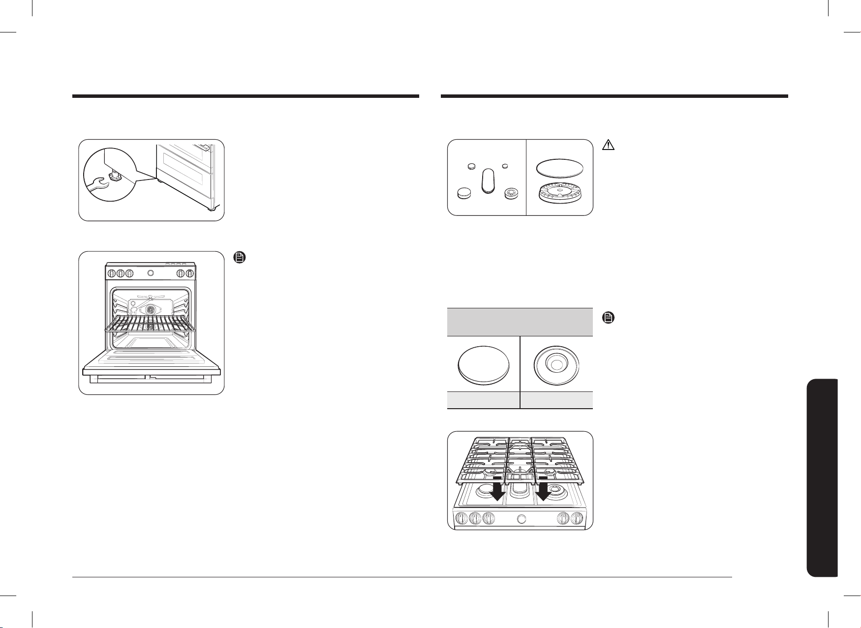
Français 25
Instructions d’installation
Étape 12 : Assemblage des brûleurs de surface
ATTENTION
N’utilisez les brûleurs de surface que si toutes les
pièces du brûleur sont installées.
1. Placez les têtes des brûleurs de surface au-
dessus des coupelles de ces derniers, comme
illustré à droite. Les électrodes s’insèrent dans
la fente située au bas des têtes. Assurez-vous
que les têtes des brûleurs de surface sont
plates et parallèles à la table de cuisson.
2. Placez les chapeaux de taille correspondante
au-dessus de chaque tête de brûleur de
surface.
Brûleur à mijoter de précision
(arrière droite)
Surface plane Ligne concave
REMARQUE
Les capuchons des brûleurs à mijoter de précision
(arrière droite) et du double brûleur intérieur (avant
droite) sont interchangeables.
3. Placez les grilles des brûleurs de surface
gauche, central et droite sur la table de
cuisson. Les bords des grilles doivent
correspondre aux bords de la table de cuisson.
Étape 11 : Mettre à niveau la cuisinière
Pied de nivellement
1. Assurez-vous que la cuisinière est positionnée
à l’endroit souhaité.
2. À l’aide d’une clé, mettez la cuisinière à niveau
en tournant les pieds de nivellement avant
vers l’intérieur ou l’extérieur, selon les besoins.
Dans le sens antihoraire, le pied se raccourcit
et la cuisinière s’abaisse. Dans le sens horaire,
le pied s’allonge et la cuisinière s’élève.
REMARQUE
• Le réglage des deux pieds avant est
généralement sufsant, toutefois, il convient
de régler les quatre pieds le cas échéant.
• Ne réglez les pieds de nivellement que dans
la mesure où cela est nécessaire pour mettre
la cuisinière à niveau. Le fait d’allonger les
pieds de nivellement plus que nécessaire ou
de retirer des pieds peut rendre la cuisinière
instable.
3. Si la cuisinière se trouve à côté ou entre des
armoires, assurez-vous que la table de cuisson
(sans les grilles des brûleurs de surface) est de
niveau avec les comptoirs.
4. Placez une grille de four à la position de la
grille centrale.
5. Vériez le niveau de la cuisinière avec un
niveau de menuisier en appliquant les deux
positions indiquées à droite.
6. Une fois que la cuisinière est de niveau,
éloignez-la du mur en la faisant glisser pour
pouvoir installer le support anti-basculement.
DG68-01650A-02_IM_NSY6DG8550SRAA_EN+MES+CFR.indb 25DG68-01650A-02_IM_NSY6DG8550SRAA_EN+MES+CFR.indb 25 2024-12-03 오후 4:13:482024-12-03 오후 4:13:48
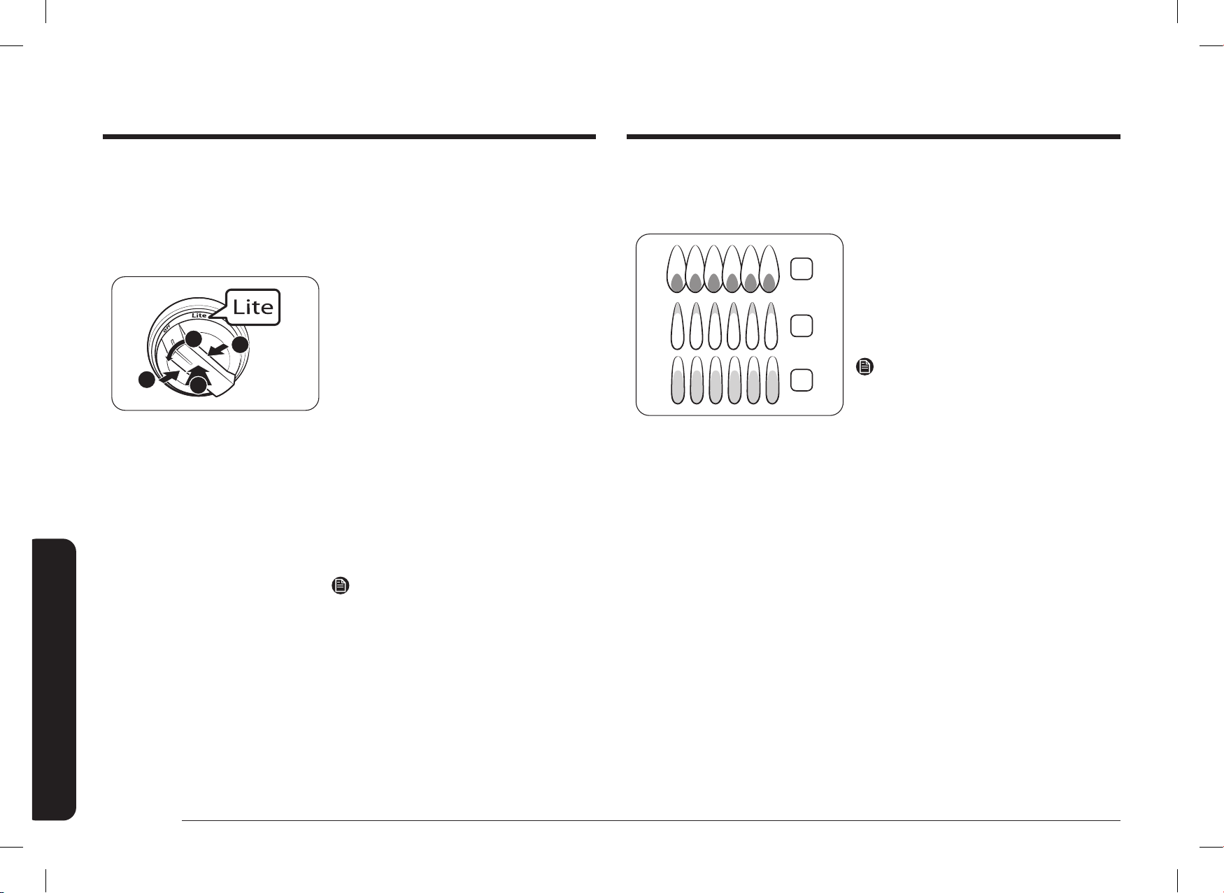
26 Français
Instructions d’installation
Instructions d’installation
Contrôle de la qualité de la amme :
Toutes les ammes de combustion doivent être contrôlées visuellement pour déterminer leur
qualité.
2
3
1
1. Flammes bleues douces—Normales pour un
fonctionnement au gaz naturel.
2. Pointes extérieures jaunes–normal pour un
fonctionnement au GPL.
3. Flammes jaunes–ce n’est pas normal, quel que
soit le type de gaz utilisé; appelez le service
après-vente.
REMARQUE
Si la amme du brûleur ressemble à 3, la cuisinière
ne doit pas être utilisée avant d’avoir été réparée.
Appelez le service après-vente. Les ammes
normales du brûleur doivent ressembler à 1 ou 2,
selon le type de gaz que vous utilisez.
Étape 13 : Vériez l’allumage des brûleurs de surface
Vériez le fonctionnement de tous les brûleurs de la table de cuisson et du four après avoir
installé et assemblé la cuisinière, vérié l’étanchéité des conduites d’alimentation en gaz et
branché le cordon d’alimentation électrique.
Tous les brûleurs de surface et du four disposent d’un allumage électronique.
3
2
1
1
Pour allumer un brûleur de surface :
1. Appuyez sur le bouton intégré au bouton.
2. Appuyez sur le bouton de commande et
tournez-le en position Lite pour ce brûleur
de surface. Un « clic » signale que le système
d’allumage électronique est fonctionnel.
Le brûleur s’allume en 4 secondes environ,
après que l’air ait été purgé du conduit
d’alimentation.
3. Une fois le brûleur allumé, tournez le bouton
de commande jusqu’au réglage souhaité. Le
« clic » s’arrête et la hauteur de la amme
passe de Max. à Min. lorsque vous tournez le
bouton de commande.
4. Répétez les étapes 1 à 3 pour vérier
successivement le fonctionnement de chaque
brûleur de surface.
REMARQUE
Placez les aliments dans le four après le
préchauffage si la recette l’exige. Le préchauffage
est important pour de bons résultats de cuisson.
Une fois que le four a atteint la température de
cuisson souhaitée, il émet un signal sonore.
DG68-01650A-02_IM_NSY6DG8550SRAA_EN+MES+CFR.indb 26DG68-01650A-02_IM_NSY6DG8550SRAA_EN+MES+CFR.indb 26 2024-12-03 오후 4:13:492024-12-03 오후 4:13:49
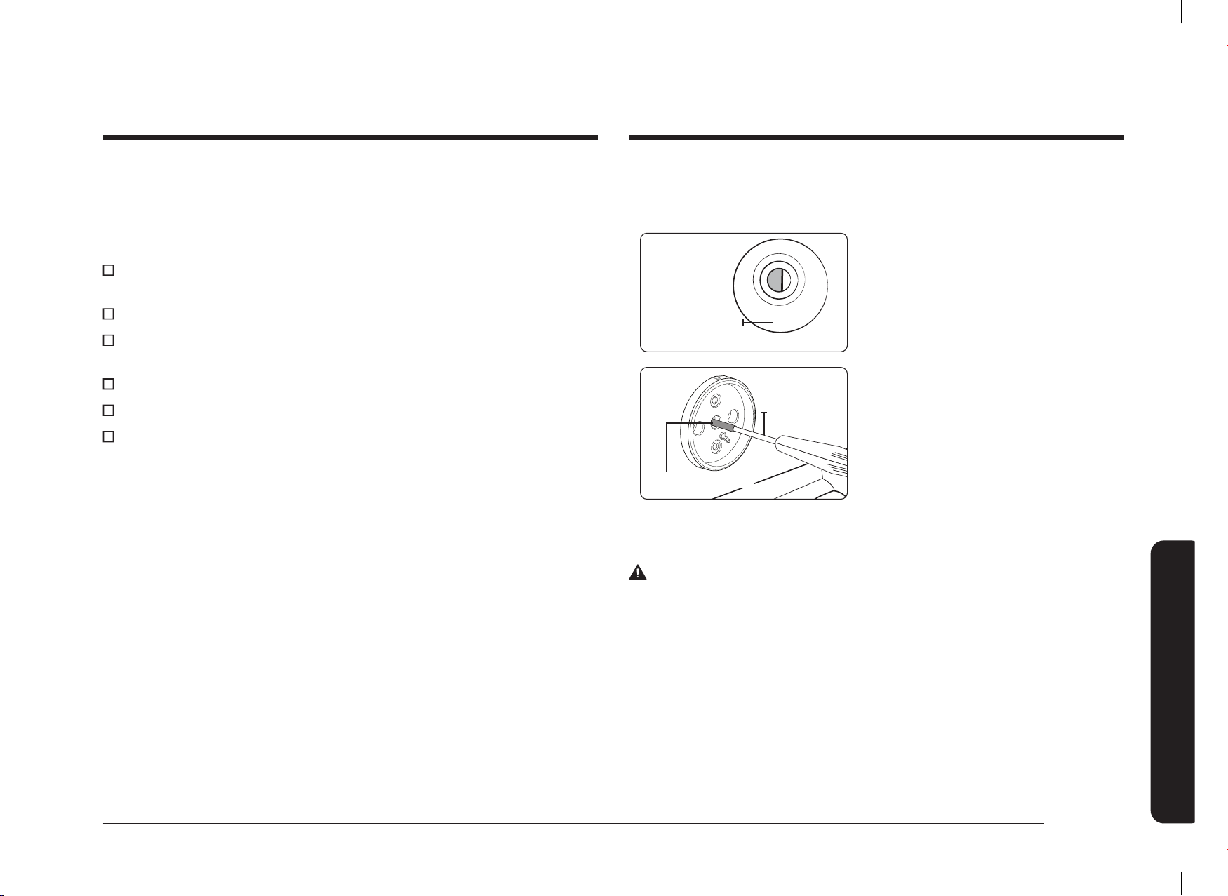
Français 27
Instructions d’installation
Pour ajuster le réglage de la amme basse
Repérez quel brûleur présente un taux de mijotage trop élevé ou trop faible à l’aide des
graphiques du panneau collecteur.
Vis de réglage
de la mijoteuse
1. Tournez un bouton en position Lo (bas)
et retirez le bouton de la tige de la vanne
pendant que la amme est allumée.
Petit tournevis
Tige de la vanne
2. Poussez délicatement le tournevis dans la tige
de la vanne, jusqu’à ce qu’il touche la vis de
réglage du mijotage. Assurez-vous que la tête
plate du tournevis est logée dans la rainure de
la vis de réglage.
3. Tournez la vis de réglage de la vanne dans
le sens horaire pour diminuer le débit de
amme du réglage Lo (bas), ou tournez la
vis de réglage dans le sens antihoraire pour
augmenter le débit de amme du réglage Lo
(bas).
AVERTISSEMENT
1. Ne retirez pas complètement la vis de réglage de la vanne de la tige de la vanne.
Ne desserrez pas plus de 3 tours la vis de réglage de la vanne. La vis de réglage de la
vanne fait partie intégrante de l’ensemble de la vanne de gaz. Si vous retirez la vis de
réglage de la vanne, le gaz fuira.
2. Après avoir ajusté la vis de réglage de la vanne, vériez l’absence de fuites de gaz.
Étape 14 : Liste de contrôle de l’installation nale
Vous venez de terminer l’installation de votre cuisinière. Vériez que toutes les commandes sont
en position Off (arrêt) et que le ux d’air de ventilation vers la cuisinière n’est pas obstrué.
Voici une liste de contrôle qui permet de conrmer que votre cuisinière est installée en toute
sécurité et prête à fonctionner.
La conduite de gaz a été correctement raccordée à la cuisinière. Le gaz a été allumé.
Tous les raccords ont été vériés pour voir s’il y a des fuites.
La cuisinière est branchée dans une prise électrique correctement mise à la terre.
Le support anti-basculement approuvé est correctement installé et enclenché avec la
cuisinière.
La cuisinière est mise à niveau et repose fermement sur un sol solide et plat.
Les brûleurs de surface au gaz ont été correctement assemblés.
Le bon fonctionnement de tous les brûleurs a été testé.
DG68-01650A-02_IM_NSY6DG8550SRAA_EN+MES+CFR.indb 27DG68-01650A-02_IM_NSY6DG8550SRAA_EN+MES+CFR.indb 27 2024-12-03 오후 4:13:492024-12-03 오후 4:13:49
UNE QUESTION? UN COMMENTAIRE?
PAYS CENTRE DE CONTACT SITE WEB
U.S.A
Consumer Electronics
1-800-SAMSUNG (726-7864) www.samsung.com/us/support
CANADA 1-800-SAMSUNG(726-7864)
www.samsung.com/ca/support (English)
www.samsung.com/ca_fr/support (French)
DG68-01650A-02
Numérisez le code QR* ou
consultez le site Internet
www.samsung.com/spsn pour
regarder nos vidéos et nos
émissions en direct
* Nécessite l’installation d’un lecteur sur votre
téléphone intelligent
Numérisez le code QR à l’aide de
votre téléphone intelligent
DG68-01650A-02_IM_NSY6DG8550SRAA_EN+MES+CFR.indb 28DG68-01650A-02_IM_NSY6DG8550SRAA_EN+MES+CFR.indb 28 2024-12-03 오후 4:13:492024-12-03 오후 4:13:49