
INSTALLATION MANUAL
Model
RMXS48LVJU
English
Español
Français
Installation manual
Manuel d’installation
Manual de instalación
00_CV_3P329623-1.fm Page 1 Friday, November 9, 2012 6:43 PM
1 English
CONTENTS
1. SAFETY PRECAUTIONS ........................................................ 1
2. INTRODUCTION...................................................................... 3
2-1. Combination...................................................................... 3
2-2. Standard operation limit .................................................... 3
2-3. Spec list ............................................................................ 3
2-4. Electrical properties .......................................................... 3
2-5. Standard supplied accessories ......................................... 4
2-6. Option accessory .............................................................. 4
3. BEFORE INSTALLATION........................................................ 4
4. SELECTING INSTALLATION SITE ......................................... 4
5. PRECAUTIONS ON INSTALLATION ...................................... 6
6. FIELD WIRING ........................................................................ 6
6-1. Wiring connection example for whole system................... 6
6-2.
How to lay the power supply wiring and transmission wiring
...... 7
6-3. How to connect the power supply wiring........................... 7
6-4. Inter-unit wiring connection procedure..............................8
7. PRECAUTIONS ON REFRIGERANT PIPING......................... 8
7-1. Installation tools ................................................................ 8
7-2. Selecting piping material...................................................8
7-3. Protection against contamination when installing pipes.... 8
7-4. Pipe connection................................................................. 8
7-5. Connecting the refrigerant piping...................................... 8
7-6. Heat insulation of piping.................................................... 9
7-7. Example of connection.................................................... 10
7-8. Air tight test and vacuum drying......................................11
8. ADDITIONAL REFRIGERANT CHARGE ..............................12
8-1. Before adding refrigerant ................................................12
8-2. Checking the refrigerant tank..........................................12
8-3. Adding refrigerant............................................................12
9. POST-WORK CHECKS.........................................................12
10. TEST RUN ............................................................................. 13
10-1.Power On–Check Operation.......................................... 13
10-2.Temperature control operation checklist........................13
11. CAUTION FOR REFRIGERANT LEAKS ............................... 14
1. SAFETY PRECAUTIONS
• Read these SAFETY PRECAUTIONS carefully to ensure correct installation.
• This manual classifies the precautions into DANGER, WARNING and CAUTION.
Be sure to follow all the precautions below: they are all important for ensuring safety.
DANGER ........ Indicates an imminently hazardous situation which, if not avoided, will result in death or serious
injury.
WARNING
...... Failure to follow any of WARNING is likely to result in such grave consequences as death or serious
injury.
CAUTION ....... Failure to follow any of CAUTION may in some cases result in grave consequences.
• The following safety symbol is used throughout this manual:
• After completing installation, test the unit to check for installation errors. Give the user adequate instructions
concerning the use and cleaning of the unit according to the Operation Manual.
Never attempt.
DANGER
• Refrigerant gas is heavier than air and replaces oxygen. A massive leak could lead to oxygen depletion,
especially in basements, and an asphyxiation hazard could occur leading to serious injury or death.
• If the refrigerant gas leaks during installation, ventilate the area immediately.
Refrigerant gas may produce a toxic gas if it comes in contact with fire such as from a fan heater, stove or cooking device.
Exposure to this gas could cause severe injury or death.
• After completing the installation work, check that the refrigerant gas does not leak.
Refrigerant gas may produce a toxic gas if it comes in contact with fire such as from a fan heater, stove or cooking device.
Exposure to this gas could cause severe injury or death.
• Do not ground units to water pipes, telephone wires or lightning rods because incomplete grounding could
cause a severe shock hazard resulting in severe injury or death, and to gas pipes because a gas leak could
result in an explosion which could lead to severe injury or death.
• Safely dispose of the packing materials.
Packing materials, such as nails and other metal or wooden parts, may cause stabs or other injuries.
Tear apart and throw away plastic packaging bags so that children will not play with them.
Children playing with plastic bags face the danger of death by suffocation.
• Do not install unit in an area where flammable materials are present due to risk of explosion resulting in serious
injury or death.
• Do not ground units to telephone wires or lightning rods because lightning strikes could cause a severe shock
hazard resulting in severe injury or death, and to gas pipes because a gas leak could result in an explosion
which could lead to severe injury or death.
01_EN_3P329623-1.fm Page 1 Friday, November 9, 2012 6:50 PM
English 2
WARNING
• Installation shall be left to the authorized dealer or another trained professional.
Improper installation may cause water leakage, electrical shock, fire, or equipment damage.
• Install the air conditioner according to the instructions given in this manual.
Incomplete installation may cause water leakage, electrical shock, fire or equipment damage.
• Be sure to use the supplied or exact specified installation parts.
Use of other parts may cause the unit to come to fall, water leakage, electrical shock, fire or equipment damage.
• Install the air conditioner on a solid base that is level and can support the weight of the unit.
An inadequate base or incomplete installation may cause injury or equipment damage in the event the unit falls off the base or comes loose.
• Electrical work shall be carried out in accordance with the installation manual and the national, state and local
electrical wiring codes.
Insufficient capacity or incomplete electrical work may cause electrical shock, fire or equipment damage.
• Be sure to use a dedicated power circuit. Never use a power supply shared by another appliance.
Follow all appropriate electrical codes.
• For wiring, use a wire or cable long enough to cover the entire distance with no splices if possible.
Do not use an extension cord. Do not put other loads on the power supply.
Use only a separate dedicated power circuit.
(Failure to do so may cause abnormal heat, electric shock, fire or equipment damage.)
• Use the specified types of wires for electrical connections from the BP unit to the indoor and outdoor units.
Follow all state and local electrical codes.
Firmly clamp the inter-unit wire so their terminals receive no external stresses.
Incomplete connections or clamping may cause terminal overheating, fire or equipment damage.
• After connecting all wires be sure to shape the cables so that they do not put undue stress on the electrical
covers, panels or terminals.
Install covers over the wires. Incomplete cover installation may cause terminal overheating, electrical shock, fire or equipment damage.
• When installing or relocating the system, be sure to keep the refrigerant circuit free from all substances other
than the specified refrigerant (R410A), such as air.
(Any presence of air or other foreign substance in the refrigerant circuit causes an abnormal pressure rise which may result in rupture,
resulting in injury.)
• During pump-down, stop the compressor before removing the refrigerant piping.
If the compressor is still running and the stop valve is open during pump-down, air will be sucked in when the refrigerant piping is removed,
causing abnormally high pressure which could lead to equipment damage or and personal injury.
• During installation, attach the refrigerant piping securely before running the compressor.
If the refrigerant pipes are not attached and the stop valve is open during installation, air will be sucked in when the compressor is run,
causing abnormally high pressure which could lead to equipment damage and personal injury.
• Be sure to install a ground fault circuit interrupter.
Failure to install a ground fault circuit interrupter may result in electrically shocks, or fire personal injury.
CAUTION
• Do not install the air conditioner where gas leakage would be exposed to open flames.
If the gas leaks and builds up around the unit, it may catch fire.
• Establish drain piping according to the instructions of this manual.
Inadequate piping may cause water damage.
• Tighten the flare nut according to the specified torque. A torque wrench should be used.
If the flare nut is tightened too much, the flare nut may crack over time and cause refrigerant leakage.
• Do not touch the heat exchanger fins.
Improper handling may result in injury.
• Be very careful about product transportation.
Some products use PP bands for packaging. Do not use any PP bands for a means of transportation. It is dangerous.
• Make sure to provide for adequate measures in order to prevent that the outdoor unit be used as a shelter by
small animals.
Small animals making contact with electrical parts can cause malfunctions, smoke or fire. Please instruct the customer to keep the area
around the unit clean.
• The temperature of refrigerant circuit will be high, please keep the inter-unit wire away from copper pipes that
are not thermally insulated.
• Electrical work must be performed in accordance with the NEC/CEC by authorized personnel only.
01_EN_3P329623-1.fm Page 2 Friday, November 9, 2012 6:50 PM
3 English
2. INTRODUCTION
1.
This series uses R410A new refrigerant. Be absolutely sure to
comply with “7. PRECAUTIONS ON REFRIGERANT PIPING”,
because even greater caution is needed to prevent impurities
from entering R410A (mineral oils and water).
2.
The design pressure is 478 PSI (3.3 MPa), which means that pip-
ing may be thicker than conventionally, so please refer to “7. PRE-
CAUTIONS ON REFRIGERANT PIPING”.
3.
This is a mixed refrigerant, so charge as a liquid when adding
refrigerant.
(If charged as a gas, the composition of the refrigerant may
change, preventing normal operation.)
4.
The indoor unit must use R410A. See the catalog for indoor unit
and BP unit models which can be connected. (Normal operation
is not possible when connected to other units.)
5.
The power supply of this series is single-phase, 208/230V (60Hz).
2-1 Combination
The indoor units can be installed in the following range.
• Be sure to connect a dedicated indoor unit. See the catalog
for indoor unit models which can be connected.
• Total capacity/quantity of indoor units
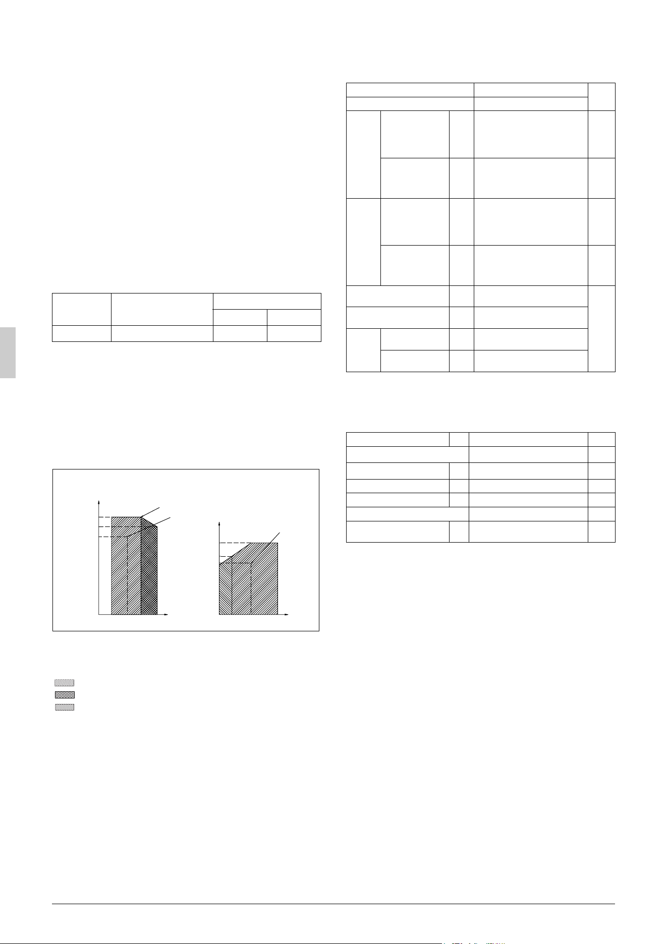
2-2 Standard operation limit
Normal operation
The figures below assume following operating conditions for indoor
and outdoor units:
Equivalent pipe length
From outdoor unit to BP unit..................................... 16.4 ft (5 m)
From BP unit to indoor unit.......................................... 9.8ft (3 m)
Level difference ............................................................. 0 ft (0 m)
(H/P model only)
A Outdoor temperature (°FDB / °CDB)
B Indoor temperature (°FWB / °CWB)
C Outdoor temperature (°FWB / °CWB)
D Indoor temperature (°FDB / °CDB)
Range for continuous operation
Range for pull down operation
Range for warming up operation
2-3 Spec list
For operating conditions marked with a *(a)(b) in the table, see “2-2
Standard operation limit”.
2-4 Electrical properties
For operating conditions marked with a *(c) in the table, see “2-2
Standard operation limit”.
Outdoor unit Total capacity of indoor units
Quantity of indoor units
Max. Min.
RMXS48LVJU 24000 - 62000 Btu/h 8 2
Cooling Heating
*(b)
B
*(c)
A
C
D
*(a)
115 (46)
104 (40)
50
(10)
95 (35)
23 (–5)
60 (15.5)
43 (6)
50 (10)
41 (5)
5 (–15)
73
(23)
66
(19)
82
(28)
50
(10)
57
(14)
70
(21)
82
(28)
57
(14)
unit : ˚F(˚C)
Model name RMXS48LVJU
Remarks
Refrigerant type
R410A
Wall
mounted
Cooling
performance
(MBh)
(kW)
48
14.1
* (a)
Heating
performance
(MBh)
(kW)
54
15.8
* (b)
Energy use during
cooling
(kW) 4.64
* (a)
Energy use during
heating
(kW)
3.98
* (b)
Duct
Cooling
performance
(MBh)
(kW)
48
14.1
* (a)
Heating
performance
(MBh)
(kW)
54
15.8
* (b)
Energy use during
cooling
(kW) 5.13
* (a)
Energy use during
heating
(kW)
5.27
* (b)
External dimensions
(height × width × depth)
(inch)
(mm)
52-15/16 × 35-7/16 × 12-5/8
1345 × 900 × 320
Mass
(lb.)
(kg)
283
129
Connec-
tion pip-
ing
Gas line piping
(inch)
(mm)
φ
3/4
φ
19.1
Liquid line piping
(inch)
(mm)
φ
3/8
φ
9.4
Model name
H/P
RMXS48LVJU
Remarks
Phase
Single
Frequency
(Hz)
60Hz
Voltage
(V)
208/230V
Voltage tolerance range
(%) ±10
Rated current for fuses
30
Maximum outdoor unit operat-
ing current
(A)
27
* (c)
01_EN_3P329623-1.fm Page 3 Friday, November 9, 2012 6:50 PM
English 4
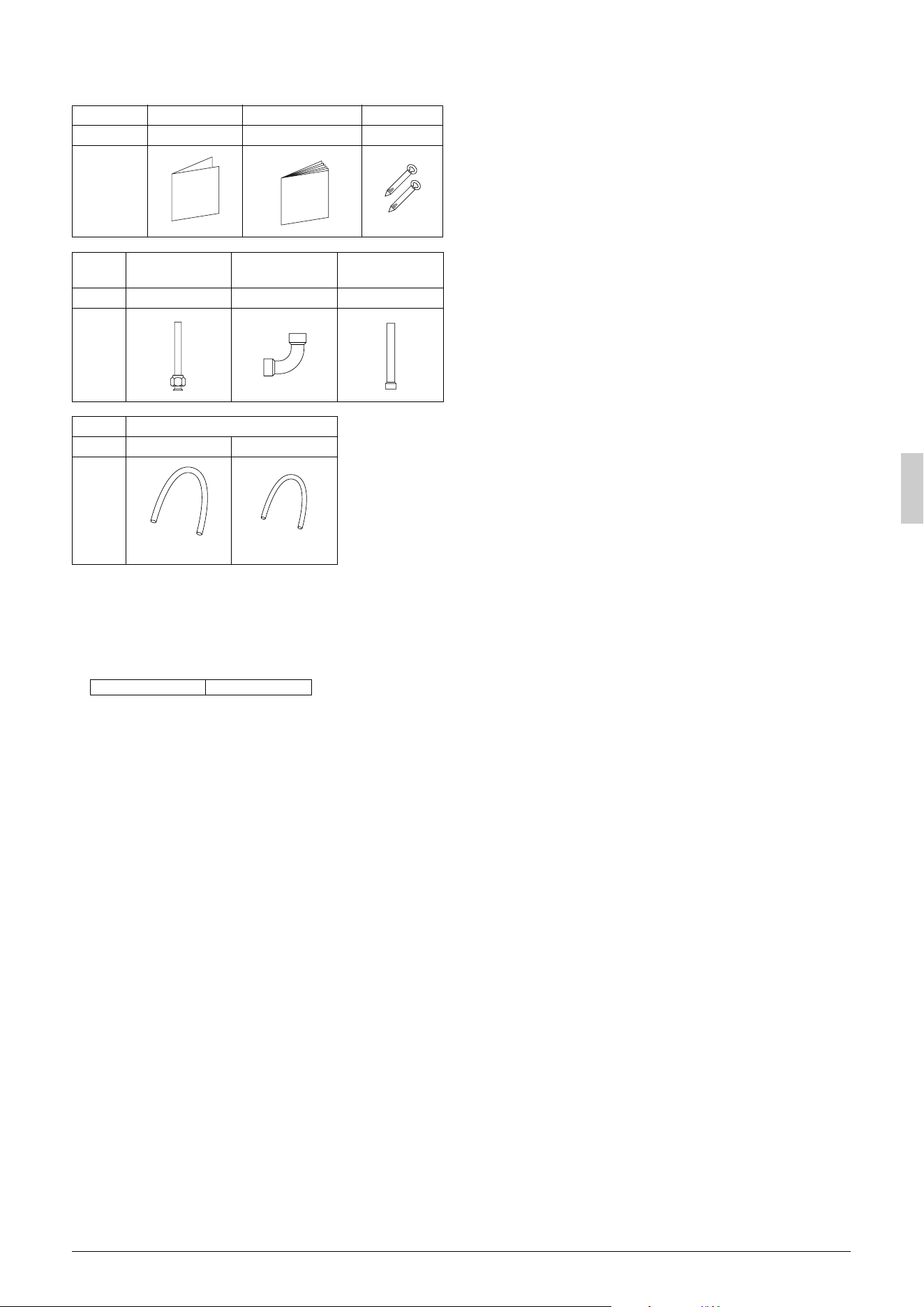
2-5 Standard supplied accessories
Make sure that the accessories shown below are all present.
(The accessories can be found behind the front panel.)
(Refer to figure 30)
1. Accessories
2. Screw for front panel
3. Front panel
2-6 Option accessory
• Refrigerant branching kit
* See “7. PRECAUTIONS ON REFRIGERANT PIPING” for
details on how to connect refrigerant branch kits and how many
are needed.
3. BEFORE INSTALLATION
<Transporting the Unit>
As shown in figure 2, bring the unit slowly. (Take care not to let hands
or things come in contact with rear fins.)
(Refer to figure 2)
1. Air outlet grille
2. Intake hole
3. Corner
4. Outdoor unit
5. Handle
6. Front
7. Rear
8. Always hold the unit by the corners, as holding it by the
side intake holes on the casing may cause them to
deform.
Use only accessories and parts which are of the designated specifi-
cation when installing.
4. SELECTING INSTALLATION SITE
(1) Select an installation site where the following conditions are
satisfied and that meets with your customer’s approval.
• Places which are well-ventilated.
• Places where the unit does not bother next-door neighbors.
• A locations where small animals will not make nests in the unit.
• Safe places which can withstand the unit’s weight and vibration
and where the unit can be installed level.
• Locations not exposed to rain.
• A locations where there is enough space to install the unit.
• Places where the indoor and outdoor unit’s piping and wiring
lengths come within the allowable ranges.
• A location where there is no risk of flammable gas leaking.
(2) If the unit is installed in a location where it might be
exposed to strong wind, install as per figure 3.
• 16.4 ft/sec (5 m/sec) or more strong wind blown against the out-
door unit’s air outlet causes the outdoor unit to deteriorate in air
capacity and suck in the air blown out of its air outlet (short cir-
cuit), and the following effects may result.
• Drop in performance.
• Increased frost formation in heating mode.
• Shutting down due to increase in pressure.
• If very strong wind blows continuously on the side of the outdoor
unit with the outlet vent, the fan may turn in reverse at high
speed and break, so install as per figure 3.
(Refer to figure 3)
1. Turn the air outlet side toward the building’s wall, fence or
windbreak screen.
2. Air inlet grille
3. Ensuring there is enough space for installing the unit.
4. Set the outlet side at a right angle to the direction of the
wind.
5. Strong wind
6. Blown air
(3) In installing the unit in a place frequently exposed to snow,
pay special attention to the following:
• Elevate the foundation as high as possible.
• Attach the snow hood (field supply).
• Remove the rear inlet grille to prevent snow from accumulating
on the rear fins.
(4) The outdoor unit may short circuit depending on its environment,
so use the louvers (field supply).
(5) The refrigerant gas (R410A) is a safe, non-toxic and non-flam-
mable gas, but if it leaks into the room, the concentration may
exceed tolerance levels, especially in small rooms, so steps need
to be taken to prevent refrigerant leakage. See the equipment
design reference for details.
(6) Inverter-type air conditioners sometimes cause static in other
electrical appliances.
When selecting an installation location, make sure the air condi-
tioner and all wiring are sufficiently far away from radios, comput-
ers, stereos, and other appliances, as shown in figure 1.
Particularly for locations with weak reception, ensure there is a
distance of at least 9.8 ft (3 m) for indoor remote controllers,
place power supply wiring and inter-unit wiring in conduits, and
ground the conduits. Use shielded wire for inter-unit wiring.
(Refer to figure 1)
1. Indoor unit
2. Branch switch (ground-fault circuit interrupter)
3. Remote controller
4. Personal computer or radio
5. BP unit
(7) Space needed for installation
<Precautions when installing units in series>
• The direction for inter-unit piping is either forward or down when
installing units in series.
• If the piping is brought out from the back, the outdoor unit will
require at least 10 inch (250 mm) from its right side.
(7)-1 IN CASE OBSTACLES EXIST ONLY IN FRONT OF THE
AIR INLET
When nothing is obstructing the top
1.
Installation of single unit
• In case obstacles exist only in front of the air inlet
(Refer to figure 4-[1])
• In case obstacles exist in front of the air inlet and on both sides
of the unit (Refer to figure 4-[2])
Name Regarding use Installation manual Binding band
Quantity 1 1 6 pcs.
Shape
Name
Gas side
accessory pipe (1)
Gas side
accessory pipe (2)
Gas side
accessory pipe (3)
Quantity 1 pc. 1 pc. 1 pc.
Shape
Name Insulation tube
Quantity 1 pc. 1 pc.
Shape
REFNET joint KHRP26M22T
(large)
(small)
01_EN_3P329623-1.fm Page 4 Friday, November 9, 2012 6:50 PM
5 English
2.
In case of installing multiple units (2 units or more) in lateral con-
nection per row
• In case obstacles exist in front of the air inlet and on both sides
of the unit (Refer to figure 4-[3])
When something is obstructing the top
1.
Installation of single unit
• In case obstacles exist only in front of the air inlet
(Refer to figure 5-[1])
• In case obstacles exist in front of the air inlet and on both sides
of the unit (Refer to figure 5-[2])
2.
In case of installing multiple units (2 units or more) in lateral con-
nection per row
• In case obstacles exist in front of the air inlet and on both sides
of the unit (Refer to figure 5-[3])
(7)-2 IN CASE OBSTACLES EXIST IN FRONT OF THE OUTLET
SIDE
When nothing is obstructing the top
1.
Installation of single unit (Refer to figure 6-[1])
2.
In case of installing multiple units (2 units or more) in lateral con-
nection per row (Refer to figure 6-[2])
When something is obstructing the top
1.
Installation of single unit (Refer to figure 6-[3])
2.
In case of installing multiple units (2 units or more) in lateral con-
nection per row (Refer to figure 6-[4])
(7)-3 IN CASE OBSTACLES EXIST IN FRONT OF BOTH THE
AIR INLET AND OUTLET SIDES
Pattern 1: Where obstacle in front of the air outlet is higher than the
unit.
(There is no height limit for obstructions on the intake side.)
When nothing is obstructing the top
1.
Installation of single unit (Refer to figure 7-[1])
2.
In case of installing multiple units (2 units or more) in lateral con-
nection per row (Refer to figure 7-[2])
When something is obstructing the top
1.
Installation of single unit (Refer to figure 7-[3])
Relation of dimensions of H, A, and L are shown in the table below.
inch (mm)
Note
Get the lower part of the frame sealed so that air from the outlet
does not bypass.
2.
Series installation (up to 2 units) (Refer to figure 7-[4])
Relation of dimensions of H, A, and L are shown in the table
below.
inch (mm)
Note
1. Get the lower part of the frame sealed so that air from the out-
let does not bypass.
2. Only two units at most can be installed in series.
Pattern 2: Where obstacles in front of the air outlet is lower than the
unit.
(There is no height limit for obstructions on the intake
side.)
When nothing is obstructing the top
1.
Installation of single unit (Refer to figure 7-[5])
2.
In case of installing multiple units (2 units or more) in lateral con-
nection per row (Refer to figure 7-[6])
Relation of dimensions of H, A, and L are shown in the table
below.
inch (mm)
When something is obstructing the top
1.
Installation of single unit (Refer to figure 7-[7])
Relation of dimensions of H, A, and L are shown in the table
below.
inch (mm)
Note
Get the lower part of the frame sealed so that air from the outlet
does not bypass.
2.
Series installation (up to 2 units) (Refer to figure 7-[8])
Relation of dimensions of H, A, and L are shown in the table
below.
inch (mm)
Note
1. Get the lower part of the frame sealed so that air from the out-
let does not bypass.
2. Only 2 units at most can be installed in series.
(7)-4 IN CASE OF STACKED INSTALLATION
1.
In case obstacles exist in front of the outlet side
(Refer to figure 8-[1])
Note
1. No more than 2 units should be stacked.
2. About 4 inch (100 mm) is required as the dimension for laying
the upper outdoor unit’s drain pipe.
3. Shut off the Z part (the area between the upper outdoor unit
and the lower outdoor unit) so that outlet air does not bypass.
2.
In case obstacles exist in front of the air inlet
(Refer to figure 8-[2])
Note
1. No more than 2 units should be stacked.
2. About 4 inch (100 mm) is required as the dimension for laying
the upper outdoor unit’s drain pipe.
3. Shut off the Z part (the area between the upper outdoor unit
and the lower outdoor unit) so that outlet air does not bypass.
(7)-5 IN CASE OF MULTIPLE-ROW INSTALLATION (FOR ROOF
TOP USE, ETC.)
1.
In case of installing 1 unit per row (Refer to figure 9-[1])
2.
In case of installing multiple units (2 units or more) in lateral con-
nection per row (Refer to figure 9-[2])
Relation of dimensions of H, A, and L are shown in the table
below.
inch (mm)
LA
L
≤
H
0 < L
≤
1/2H 30 (750)0
1/2H < L
≤
H 40 (1000)
H < L
Set the frame to be L ≤ H
LA
L
≤
H
0 < L
≤
1/2H 40 (1000)
1/2H < L
≤
H 50 (1250)
H < L
Set the frame to be L ≤ H
LA
0 < L
≤
1/2H 10 (250)
1/2H < L
≤
H12 (300)
LA
L
≤
H
0 < L
≤
1/2H 4 (100)
1/2H < L
≤
H 8 (200)
H < L
Set the frame to be L ≤ H
LA
L
≤
H
0 < L
≤
1/2H 10 (250)
1/2H < L
≤
H12 (300)
H < L
Set the frame to be L ≤ H
LA
L
≤
H
0 < L
≤
1/2H 10 (250)
1/2H < L
≤
H12 (300)
H < L
Installation impossible.
01_EN_3P329623-1.fm Page 5 Friday, November 9, 2012 6:50 PM

English 6
5. PRECAUTIONS ON INSTALLATION
• Install making sure the unit is level and the foundation is sturdy
enough to prevent vibration noise.
• In accordance with the foundation drawing in figure 10, fix the unit
securely by means of the foundation bolts.
(Prepare 4 sets of M12 foundation bolts, nuts and washers each
which are available on the market.)
• The foundation bolts should be inserted 15/16 inch (20 mm).
(Refer to figure 10)
1. Diagram of lower surface
<Drain pipe disposal>
• Locations where drainage from the outdoor unit might be a prob-
lem.
In such locations, for example, where the drainage might drip onto
passersby, lay the drain piping using the separately sold drain
plug.
• When laying the drain, at least 4 inch (100 mm) from the bottom of
the outdoor unit is needed.
• Make sure the drain works properly.
(Watch out for water leaks if piping is brought out the bottom.)
(Refer to figure 11)
1. Drain plug
2. 4 tabs
3. Drain receiver
4. Insert the drain receiver as far as possible into the drain
plug and hook the tabs.
5. Bottom frame drain hole
6. (1) Insert the drain plug through the drain hole in the
bottom frame shown in figure 12.
(2) Turn the drain plug along the guides until it stops
(approx. 90°), and then attach the bottom frame.
7. Guide
(Refer to figure 12)
1. Air outlet side
2. Diagram of lower surface
3. Drain hole
[How to remove the transport clasp]
• A yellow transport clasp and washer are attached to the legs of
the compressor to protect the unit during transportation, so
remove them as shown in figure 13.
(Refer to figure 13)
1. Compressor
2. Securing nut
3. Washer
4. Transport clasp
5. Turn in the direction of the arrow and remove.
6. Sound-proof cover
7. Do not remove with the cover open.
(1) Open the sound-proof cover as shown in figure 13.
Do not pull the sound-proof cover or remove it from the compres-
sor.
(2) Remove the securing nut.
(3) Remove the washer.
(4) Remove the transport clasp as shown in figure 13.
(5) Retighten the securing nut.
(6) Return the sound-proof cover as it was.
6. FIELD WIRING
CAUTION
To the electrician
• Do not operate until refrigerant piping work is completed.
(If operated before complete the piping work, the compressor
may be broken down.)
• Be sure to install a ground fault circuit interrupter.
(This unit uses an inverter, so install the ground fault circuit inter-
rupter that be capable of handling high harmonics in order to
prevent malfunctioning of the ground fault circuit interrupter
itself.)
6-1 Wiring connection example for whole system
• Electrical wiring work should be done by a certified professional.
• Follow the “Electrical wiring diagram face plate” when carrying out
any electrical wiring.
Only proceed with wiring work after blocking off all power.
• Make sure the ground resistance is no greater than 4Ω .
• Attach a ground-fault circuit interrupter.
• Ground the indoor and outdoor units.
• Do not connect the ground wire to gas pipes, sewage pipes, light-
ning rods, or telephone ground wires.
• Gas pipes: can explode or catch fire if there is a gas leak.
• Sewage pipes: no grounding effect is possible if hard plastic
piping is used.
• Telephone ground wires and lightning rods: dangerous
when struck by lightning due to abnormal rise in electrical poten-
tial in the grounding.
• Use copper wire.
• When doing the electrical wiring, always shut off the power source
before working, and do not turn on the switch until all work is com-
plete.
• This unit has an inverter, so it must be grounded in order to reduce
noise and prevent it affecting other appliances, and also to
release any electrical build-up in the unit case due to leaked cur-
rent.
• Do not install a power-factor improving phase-advancing capaci-
tor under any circumstances.
(Not only will this not improve the power factor, but it might cause
a fire.)
• Connect the wire securely using designated wire and fix it with
attached clamp without applying external pressure on the termi-
nal parts (terminal for power wiring, terminal for transmission wir-
ing and ground terminal). See “6-3 How to connect the power
supply wiring”.
• Left-over wiring should not be wrapped and stuffed into the unit.
• To prevent the power wiring from being damaged by the knock
hole edges, put it in a wiring pipe or plastic tube to protect it.
• Secure the wiring with the included clamp so that it does not come
in contact with the piping or stop valve.
(See “6-3 How to connect the power supply wiring”.)
CAUTION
• Use a power wire pipe for the power supply wiring.
• Outside the unit, make sure the weak electric wiring (i.e. for the
remote controller cord, between units, etc.) and the strong elec-
tric wiring do not pass near each other, keeping them at least
2 inch (50 mm) apart.
Proximity may cause electrical interference, malfunctions, and
breakage.
• Be sure to connect the power wiring to the power wiring terminal
block and secure it as described in “6-3 How to connect the
power supply wiring”.
• Inter-unit wiring should be secured as described in “6-4 Inter-
unit wiring connection procedure”.
• Secure wiring with binding band (accessory) to avoid contact
with piping.
• Make sure the wiring and the front panel do not stick up above
the structure, and close the cover firmly.
(Refer to figure 14)
1. The power source is supplied to each BP unit
individually.
2. Branch switch and over-current interrupter (ground-fault
circuit interrupter)
3. Power supply
4. Outdoor unit
5. 16V
6. 208/230V
7. Indoor unit
8. BP unit
9. Ground wire
01_EN_3P329623-1.fm Page 6 Friday, November 9, 2012 6:50 PM
7 English
6-2 How to lay the power supply wiring and trans-
mission wiring
Let the power supply wiring and transmission wiring with a conduit
pass through one of the knockout holes on the front or side cover,
and let the transmission wiring with a conduit pass through another
knockout hole.
• For protection from uninsulated live parts, thread the power sup-
ply wiring and the transmission wiring through the included insu-
lation tube and secure it with the included binding band.
Precautions when knocking out knock holes
• Open the knock holes with a hammer or the like.
• After knocking out the holes, we recommend you remove burrs in
the knock holes and paint the edges and areas around the edges
using the repair paint to prevent rusting.
• When passing wiring through knock holes, make sure there are
no burrs, and protect the wiring with protective tape.
(Refer to figure 15)
1. Screw
2. Unfasten the screw and open the cover.
(Refer to figure 16)
1. Stop valve attachment plate
2. Power supply wiring (including ground wire) or transmis-
sion wiring.
3. Backward
4. Knockout hole
5. Sideways
6. Forward
7. Electrical Component Box
8. Terminal block (X2M)
9. Binding band (accessory)
10. Connecting power supply wiring
11. Ground wire (yellow/green)
12. Terminal block (X1M)
13. Transmission wiring
14. (To X2M [To BP unit] (F1, F2))
15. Insulation tube (large) (accessory)
16. Insulation tube (small) (accessory)
17. Cut off the insulation tube sticking out of the outdoor unit.
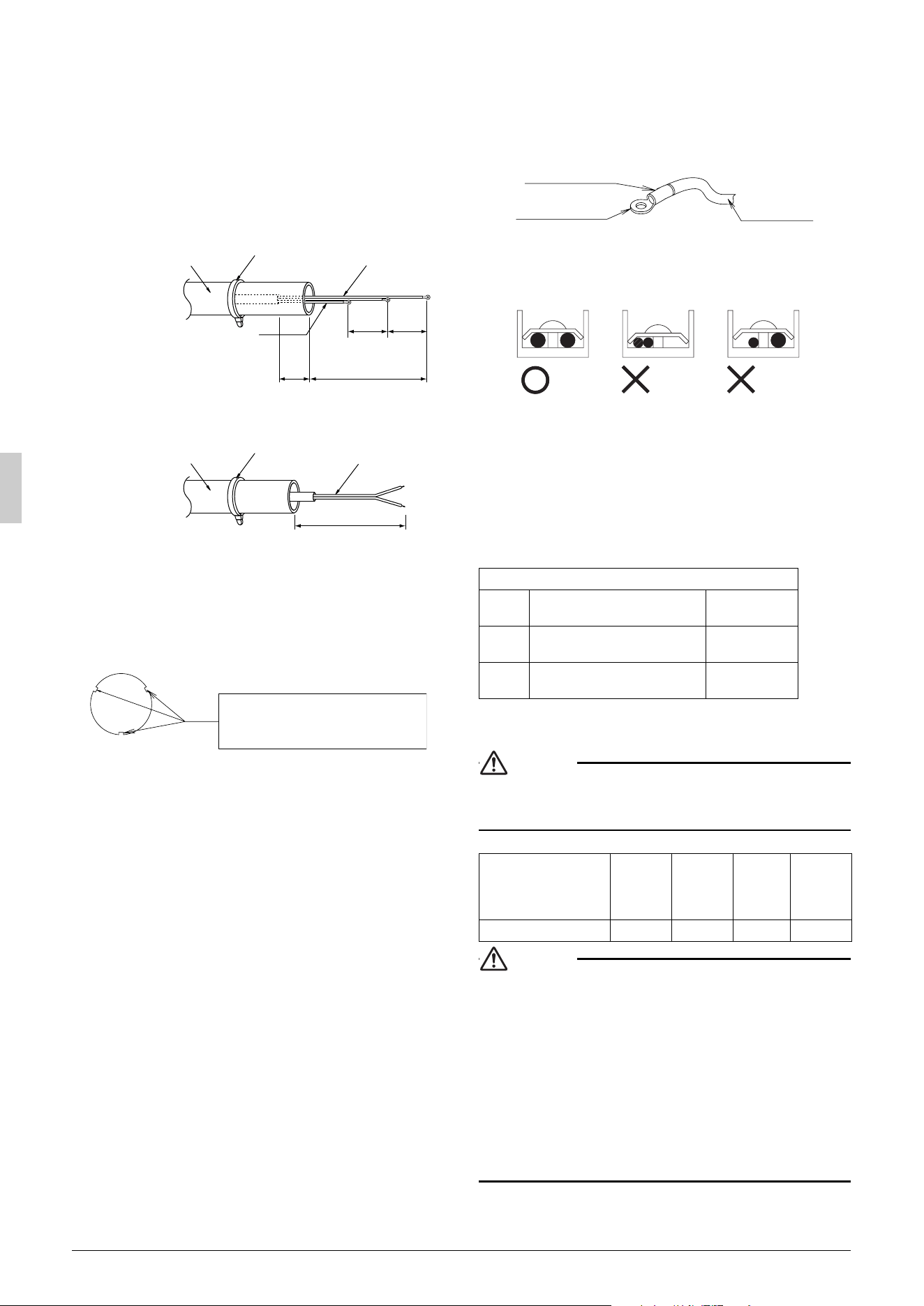
<Precautions when laying power wiring>
• Wiring of different thicknesses cannot be connected to the power
terminal block.
(Slack in the power wiring may cause abnormal heat.)
• Use sleeve-insulated round pressure terminals for connections to
the power terminal block. When none are available, connect wire
of the same diameter to both sides, as shown in the figure.
Follow the instructions below if the wiring gets very hot due to
slack in the power wiring.
• For wiring, use the designated power wire and connect firmly,
then secure using the included clamping material to prevent out-
side pressure being exerted on the terminal block.
• Use an appropriate screwdriver for tightening the terminal screws.
A screwdriver with a small head will strip the head and make
proper tightening impossible.
• Over-tightening the terminal screw may break it.
See the table below the tightening torque of the terminal screws.
6-3 How to connect the power supply wiring
CAUTION
Attach a ground-fault circuit interrupter.
• A ground-fault circuit interrupter is required in order to prevent
electric shock and fires.
CAUTION
• The wiring should be selected in compliance with local specifi-
cations. See the table above.
• Always turn off the power before doing wiring work.
• Grounding should be done in compliance with local laws and
regulations.
• Attach a ground-fault circuit interrupter.
(This unit has an inverter, so an interrupter capable of handling
high frequencies is needed to prevent malfunction of the inter-
rupter itself.)
• As shown in figure 16, when connecting the power supply wiring
to the power supply terminal block, be sure to clamp securely.
• Once wiring work is completed, check to make sure there are no
loose connections among the electrical parts in the control box.
Insulation tube
(accessory)
Binding band
(accessory)
Power supply
wiring
3 inch
(76mm)
5/8 inch
(15 mm)
2 inch
(50 mm)
or more
5/8 inch
(15 mm)
Insulation tube
(accessory)
Binding band
(accessory)
Transmission
wiring
3 inch (76mm)
<Power supply wiring>
<Transmission wiring>
Ground wire
If small animals might enter the
unit, block the knock holes with an
appropriate material (field supply).
Burr
Tightening torque
M5 Power terminal
1.76-2.15 ft·lbf
(2.39-2.91 N·m)
M4 Shield ground
0.87-1.06 ft·lbf
(1.18-1.44 N·m)
M3
Transmission wiring terminal block
0.58-0.72 ft·lbf
(0.8-0.97 N·m)
Model name
Frequency Voltage
Rated
current
for fuses
Maximum
outdoor unit
operating
current
RMXS48LVJU 60Hz 208/230V 30A 27A
Insulating sleeve
Round crimp-style
terminal
Electric Wire
Connect wires
of the same gauge
to both side.
Do not connect
wires of different
gauges.
Do not connect
wires of the same
gauge to one side.
Good Wrong
Wrong
01_EN_3P329623-1.fm Page 7 Friday, November 9, 2012 6:50 PM

English 8
6-4 Inter-unit wiring connection procedure
• Between indoor units in the same system, pass the wiring
between the units as shown in figure 17. (There is no polarity.)
(Refer to figure 17)
1. Terminal block (X2M)
2. Use balance type shield wire (with no polarity).
3. BP unit
4.
Not used for this model.
Never connect wires, or the
entire system will be damaged.
Precautions regarding the length of wiring between units
Exceeding the following limits may cause transmission malfunctions,
so observe them.
Max. wiring length Max. 656 ft (200 m)
Total wiring length Max. 984 ft (300 m)
Precautions regarding wiring between units
• Do not connect 208/230V power wiring to terminals for the
inter-unit wiring. Doing so would destroy the entire system.
• Wiring to the BP unit should be wired to F1 and F2 (To BP unit) on
the outdoor unit’s terminal block (X2M).
Note
• The above wiring should be wired using AWG 18-16 (0.75 – 1.25
mm
2
) shielded (balance type) wiring.
(See figure 16 for how to ground the shielded parts.)
• All inter-unit wiring is to be procured on site.
CAUTION
(Refer to figure 18)
1. Branch
2. Caution on branches in the wiring among BP units
3. The following branches can not be performed
7. PRECAUTIONS ON REFRIGERANT
PIPING
CAUTION
To the pipe-layer
• Do not operate the unit with the transport clasp attached. This
can cause abnormal shaking or noise. See “5. PRECAUTIONS
ON INSTALLATION” and “How to remove the transport clasp”.
7-1 Installation tools
Use the right parts to ensure tolerance and to prevent foreign matter
for entering.
Gauge manifold, charge hose, etc.
• Make sure to use installation tools that are exclusively used for
R410A installations to withstand the pressure and to prevent for-
eign materials (e.g. mineral oils such as SUNISO and moisture)
from mixing into the system.
(The screw specifications differ for R410A.)
Vacuum pump
• Use extreme caution to prevent pump oil from flowing back-
wards through the system when the pump is stopped.
• Use a vacuum pump which can evacuate to –14.6 PSI (–100.7
kPa (5Torr, –755mmHg)).
7-2 Selecting piping material
•
Use pipes that have no contaminants adhered to their inner surfaces
(such as sulfur, iron oxide, dust, cutting chips, oil and moisture). (It is
desirable that adhered oil inside the piping is 0.00006 lb. (30 mg) or
less per 32.8 ft (10 m).)
•
The wall thickness of the refrigerant piping should comply with local
laws and regulations. The design pressure for R410A is 478 PSI
(3.3 MPa).
• Use the following material for the refrigerant piping.
Material: Jointless phosphor-deoxidized copper pipe.
• Thickness and size: choose based on the piping size selection
method on the “7-8 Air tight test and vacuum drying”.
• Make sure to use the separately sold refrigerant branch kit when
branching the piping.
• Piping work should be done within the maximum length, height
difference, and length after branches set out in “7-8 Air tight test
and vacuum drying”.
• Install the refrigerant branch kit while observing the following con-
dition and referring to the installation manual offered as an acces-
sory of the kit.
(Refer to figure 19)
1.
Install the REFNET joint so it splits horizontally or vertically.
2. Horizontal surface
3. A-arrow view
4. ±30° or less
5. Level
6. Vertical is also OK
7-3 Protection against contamination when
installing pipes
• Wrap the piping to prevent moisture, dirt, dust, etc. from entering
the piping.
• Exercise caution when passing copper piping through the
through-holes and when passing them out to the outside.
7-4 Pipe connection
• See “Stop valve operation procedure” in “7-8 Air tight test and
vacuum drying” regarding handling of the stop valve.
• Only use the flare nuts included with the unit. Using different flare
nuts may cause the refrigerant to leak.
• Be sure to perform a nitrogen blow when brazing.
(Brazing without performing nitrogen replacement or releasing
nitrogen into the piping will create large quantities of oxidized film
on the inside of the pipes, adversely affecting valves and compres-
sors in the refrigerating system and preventing normal operation.)
Note
The nitrogen used when brazing while flowing the nitrogen should be
set to 2.9 PSI (0.02 MPa) (2.8 PSI / 0.019 MPa: just enough to feel a
breeze on your cheek) with the decompression valve.
• Do not mix any refrigerant other than that specified into the refrig-
erant system.
• Do not mix air into the refrigerant system.
CAUTION
Do not use a flux when brazing the refrigerant pipe joints.
Use phosphor copper brazing (BCuP-2/B-Cu93P-710/795) which
does not require flux.
(Using a chlorine flux may cause the pipes to corrode, and if it
contains fluoride it may cause the refrigerant lubricant to deterio-
rate, adversely affecting the refrigerant piping system.)
(Refer to figure 20)
1. Refrigerant pipe
2. Location to be brazed
3. Regulator
4. Nitrogen
5. Manual valve
6. Taping
7-5 Connecting the refrigerant piping
• The local inter-unit piping is connectable in four directions.
(Refer to figure 21)
1. Front panel
2. Pipe outlet panel
3. Backward
4. Sideways
5. Downward
6. Pipe outlet panel screw
7. Forward
8. Screw for front panel
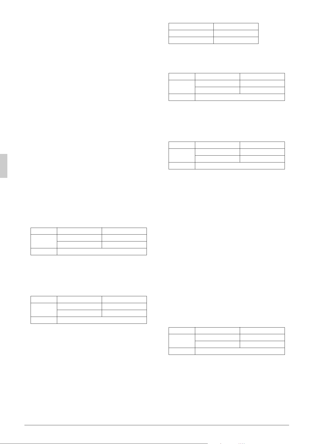
Place Installation period Protection method
Outdoor
More than a month Pinch the pipe
Less than a month
Pinch or tape the pipe
Indoor Regardless of the period
01_EN_3P329623-1.fm Page 8 Friday, November 9, 2012 6:50 PM
9 English
• When connecting the pipings downward, remove the knock-
out by making 4 holes in the middle on the each side of the
knockout with a drill.
(Refer to figure 22)
1. Dril
2. Center area around knockout hole
3. Knockout hole
4. Slit
• After knocking out the knock-out, it is recommended to apply
repair paint to the edge and the surrounding end surfaces to pre-
vent rusting.
(Refer to figure 23)
1. Bottom frame
2. Inter-unit piping
Note
Cutting out the 2 slits makes it possible to install as shown in fig-
ure 23. (Use a metal saw to cut out the slits.)
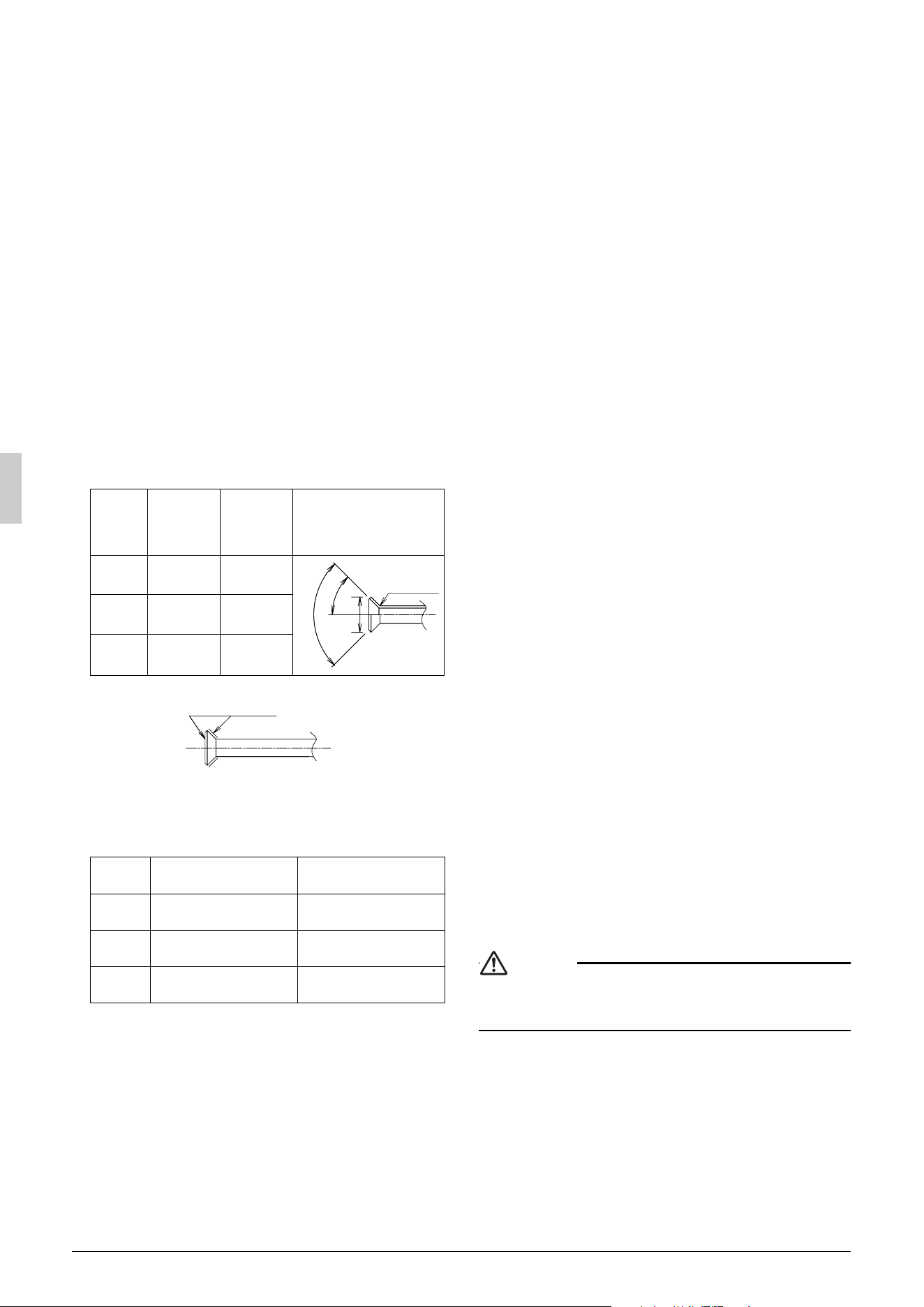
<Precautions when connecting pipes>
• Please refer to the Table 1 for the dimensions for processing
flares.
• When connecting the flare nut, coat the inner surface of the flare
with refrigeration oil and initially tighten by hand 3 or 4 turns
before tightening firmly.
• Please refer to the Table 1 for the tightening torque. (Too much
tightening will end up in splitting of the flare.)
Table 1
• If a torque wrench is not available, there is a place where the tight-
ening torque will suddenly increase if a normal wrench is used to
tighten the flare nut.
From that position, further tighten the flare nut the angle shown
below.
• After all the piping has been connected, use nitrogen to perform a
gas leak check.
(Refer to figure 24-[1])
1. Front connection
2. Gas side accessory pipe (1)
3. Gas side accessory pipe (3)
4. Gas side piping (field supply)
5. Cut at an appropriate length.
6. Gas side accessory pipe (2)
(Refer to figure 24-[2])
1. Rear-side connection
2. Gas side accessory pipe (1)
3. Gas side accessory pipe (2)
4. Gas side accessory pipe (3)
5. Gas side piping (field supply)
(Refer to figure 24-[3])
1. Side connection
2. Gas side accessory pipe (2)
3. Cut at an appropriate length.
4. Gas side piping (field supply)
5. Gas side accessory pipe (3)
6. Gas side accessory pipe (1)
(Refer to figure 24-[4])
1. Bottom connection
2. Cut at an appropriate length.
3. Gas side piping (field supply)
4. Gas side accessory pipe (3)
5. Gas side accessory pipe (1)
Precautions for connecting pipes
• Be careful not to let the inter-unit piping come into contact with the
compressor terminal cover.
Adjust the height of the insulation material on liquid pipe when it
has the possibility of getting in contact with the terminal. Also
make sure that the inter-unit piping does not touch the mounting
bolt of the compressor.
(Refer to figure 26)
1. Terminal cover
2. Compressor
3. Corking, etc.
4. Insulation material
5. Bolts
6. Inter-unit piping
• If installing the outdoor unit higher than the indoor unit, caulk the
space around insulation and tubes because condensation on the
check valve can seep through to the indoor unit side.
[Preventing foreign objects from entering]
• Plug the pipe through-holes with putty or insulating material (pro
cured locally) to stop up all gaps, as shown in figure 25.
(Insects or small animals entering the outdoor unit may cause a
short in the control box.)
(Refer to figure 25)
1. Putty or insulating material
2. (field supply)
7-6 Heat insulation of piping
• If you think the humidity inside the ceiling might exceed 86°F
(30°C) and RH80%, reinforce the insulation on the cooling piping.
(At least 0.78 inch (20 mm) thick) (Condensation may form on the
surface of the insulation.)
• Be sure to insulate the inter-unit piping (liquid and gas-side) and
the refrigerant branch kit. (Not insulating them may cause leak-
ing.)
(The highest temperature that the gas-side piping can reach is
around 248°F (120°C), so be sure to use insulating material which is
very resistant.)
CAUTION
For local insulation, be sure to insulate all the way to the pipe con-
nections inside the machine.
Exposed piping may cause leaking or burns on contact.
Pipe size
Tightening
torque
A dimen-
sions for
processing
flares
Flare shape
φ
3/8 inch
(
φ
9.5mm)
24.1-29.4 ft·lbf
(32.7-39.9N·m)
0.504-0.520 inch
(12.8-13.2mm)
φ
5/8 inch
(
φ
15.9mm)
45.6-55.6 ft·lbf
(61.8-75.4N·m)
0.760-0.776 inch
(19.3-19.7mm)
φ
3/4 inch
(
φ
19.1mm)
71.7-87.5 ft·lbf
(97.2-118.6N·m)
0.929-0.944 inch
(23.6-24.0mm)
Pipe size Further tightening angle
Recommended arm length
of tool
φ
3/8 inch
(
φ
9.5mm)
60°- 90 °
Approx. 7-7/8 inch
(200 mm)
φ
5/8 inch
(
φ
15.9mm)
30°- 60°
Approx. 11-13/16 inch
(300 mm)
φ
3/4 inch
(
φ
19.1mm)
20° - 35°
Approx. 17-11/16 inch
(450 mm)
A
45˚± 2˚
90˚± 2˚
R0.016-0.031 inch
(R0.4-0.8mm)
Refrigeration oil
01_EN_3P329623-1.fm Page 9 Friday, November 9, 2012 6:50 PM
English 10
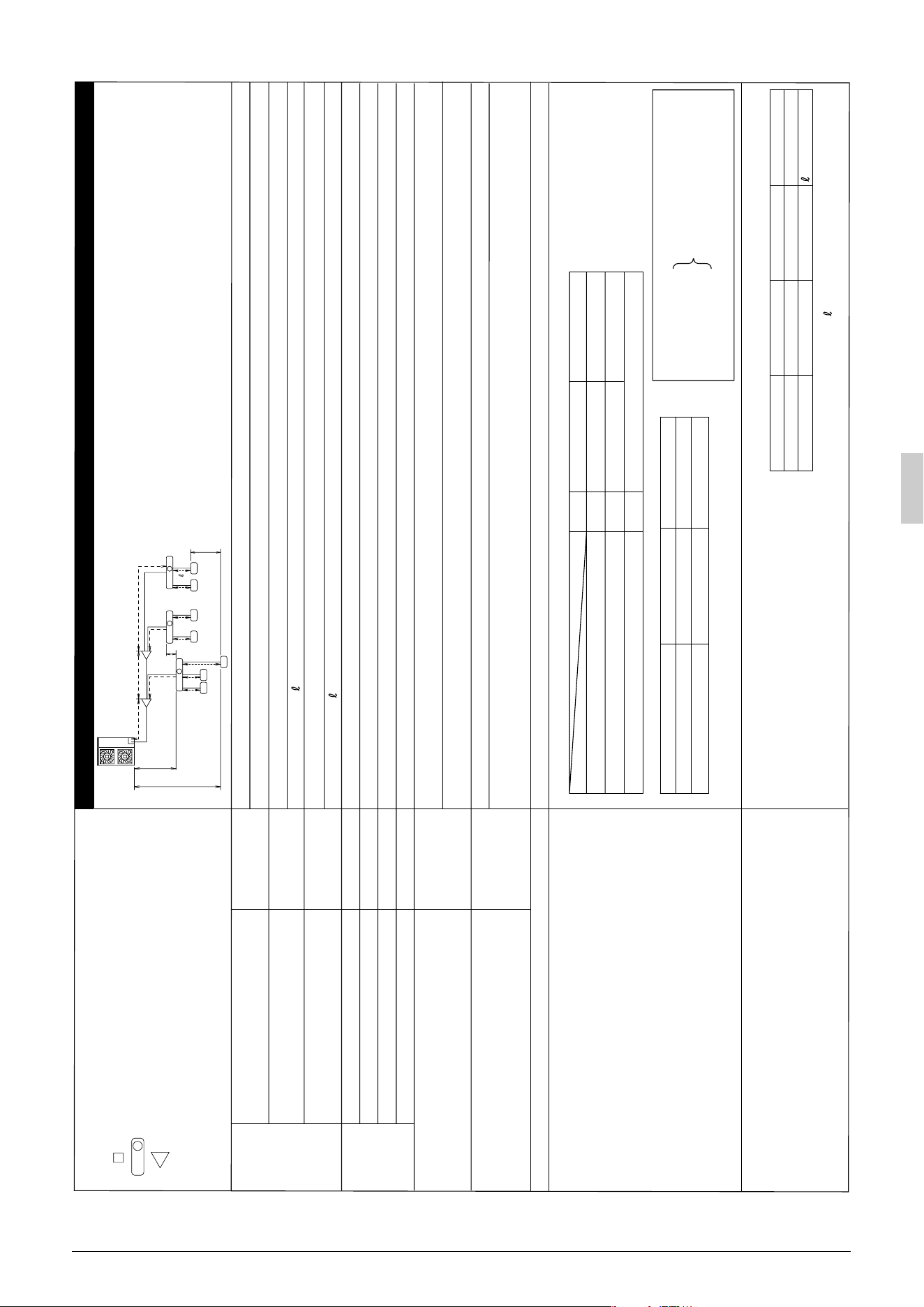
7-7 Example of connection
Example of connection
(Connection of 7 units heat pump system)
Branch with refnet joint
Maximum
allowable
length
Allowable length after the branch
∗2 Branch kit are recommanded to set as possible
as near the BP units.
c, d, e are recommanded to be as possible as short.
Between indoor and indoor units
Between BP and BP units
Between outdoor and BP units
Between outdoor and indoor units
Between BP and indoor unit
Between BP and indoor units
Between outdoor and BP units
Piping length
Piping length
Difference in height
Difference in height
Difference in height
Difference in height
1 room length
Total piping length
Total piping length
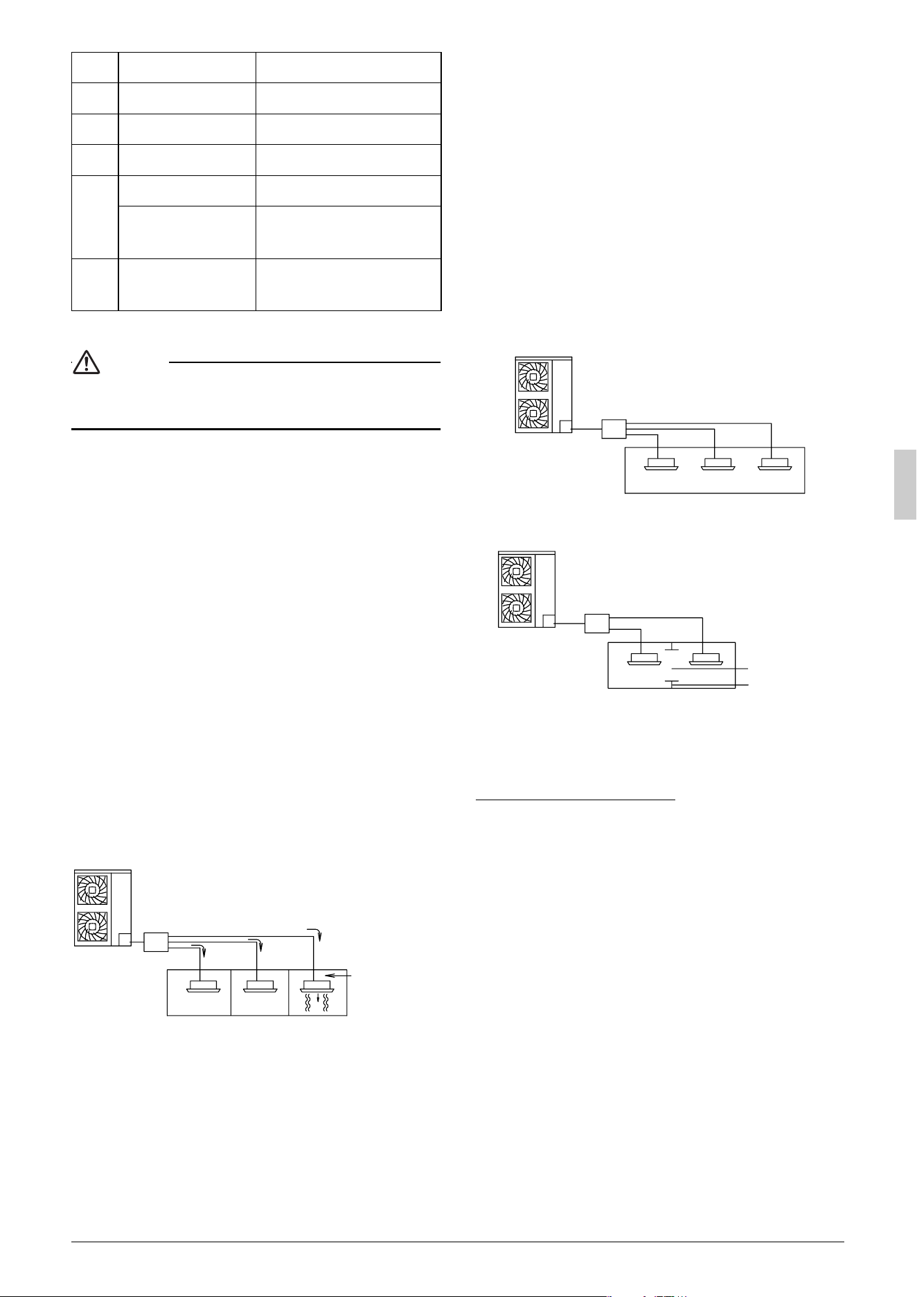
Pipe length between outdoor and BP units ≤ 180 ft (55m)
Pipe length between outdoor unit and first refrigerant branch kit (refnet joint) ≥ 16.4 ft (5m)
[Example] a ≥ 16.4 ft (5m)
Piping length between BP and indoor units: 262ft (80m)
[Example] a+b+c+d+e ≤ 180 ft (55m)
Piping length between BP and indoor unit ≤ 49 ft (15m)
Difference in height between outdoor and indoor units (H1) ≤ 98 ft (30m)
Difference in height between outdoor and BP units (H2) ≤ 98 ft (30m)
Difference in height between BP and BP units (H3) ≤ 49 ft (15m)
Refrigerant branch kit (refnet joint) name : KHRP26M22T
Difference in height between indoor and indoor units (H4) ≤ 49 ft (15m)
Piping length from first refrigerant branch kit (refnet joint) to indoor unit ≤ 131 ft (40m)
[Example] unit 6: b+c+k ≤ 131 ft (40m)
[Example] unit 5: b+e+j ≤ 131 ft (40m)
[Example] unit 3: d+h ≤ 131 ft (40m)
Allowable
height
Minimum allowable length
∗1 Since the sound of refrigerant may be transferred from
the outdoor unit to the indoor unit, make the pipe length
from the outdoor unit to the first junction 16.4 ft (5 m) or longer.
Refrigerant branch kit selection refrigerant branch kits can only be used with R410A
How to calculate the additional refrigerant to be charged
Additional refrigerant to be charged R (lb. /kg)
R should be rounded off in units of 0.1 lb. (0.1kg).
Pipe size selection
φ 1/2 × 0.031 (φ 12.7 × 0.8)
φ 5/8 × 0.039 (φ 15.9 × 1.0)
φ 1/4 × 0.031 (φ 6.4 × 0.8)
φ 3/4 × 0.039 (φ 19.1 × 1.0)
φ 5/8 × 0.031 (φ 15.9 × 1.0)
φ 3/8 × 0.031 (φ 9.5 × 0.8)
φ 3/8 × 0.031 (φ 9.5 × 0.8)
φ 3/8 × 0.031 (φ 9.5 × 0.8)
Table A
∗
Qc, Qd, Qe is total connected indoor capacity
[Example]
indoor 1: 9000 Btu/h
indoor 2: 12000 Btu/h
indoor 3: 18000 Btu/h
=>
(Gas pipe) φ5/8 × 0.031 (φ15.9 × 1.0) / (Liquid pipe) φ3/8 × 0.031 (φ9.5 × 0.8)
∗
c, d, e indicates the symbols in the figure
Gas pipe
Total indoor capacity Q
Liquid pipe
Qc, Qd, Qe ≤ 17000 Btu (5.0 kW)
Qc, Qd, Qe > 17000 Btu (5.0 kW)
• Piping size (Outer diameter × minimum thickness)
R=
+
Total length (ft / m)
of liquid piping size at
φ1/4 inch (φ6.4 mm)
×
0.015 lb./ft
(0.022 kg/m)
R=[(a+b+d+e)
×
]+[(c+f+g+h+i+j+k+ )
×
]=[ × ]+[ × ]=
0.036
(0.054)
0.015
(0.022)
0.036
(0.054)
0.015
(0.022)
8.118 → 8.1 lb.
(3.766 → 3.8kg)
234
(73)
128
(40)
×
0.036 lb./ft
(0.054 kg/m)
Total length (ft / m)
of liquid piping size at
φ3/8 inch (φ9.5 mm)
[Example] for refrigerant branch using refnet joint
unit : inch× ft (mm× m)
Between refrigerant branch kit and BP unit
Between refrigerant branch kit and refrigerant branch kit
Between outdoor unit and first refrigerant branch kit a
symbol Gas pipe Liquid pipe
b
c, d, e See the table A
indoor unit
BP unit
refrigerant branch kit (refnet joint)
Qd = 39000 Btu/h
BP
A
1
1
a
12
BP
BP
3
45
6
d
fg
h
ij
k
e
bc
H1
H4
H2
H3
A
1
2
BP
3
B
7
[Example] f+g+h+i+j+k+ ≤ 262ft (80m)
[Example] f, g, h, i, j, k, ≤ 49 ft (15m)
a:
φ
3/8 × 32 (
φ
9.5 × 10)
b:
φ
3/8 × 32 (
φ
9.5 × 10)
c:
φ
1/4 × 32 (
φ
6.4 × 10)
d:
φ
3/8 × 32 (
φ
9.5 × 10)
e:
φ
3/8 × 32 (
φ
9.5 × 10)
f :
φ
1/4 × 32 (
φ
6.4 × 10)
g:
φ
1/4 × 32 (
φ
6.4 × 10)
h:
φ
1/4 × 32 (
φ
6.4 × 10)
i :
φ
1/4 × 32 (
φ
6.4 × 10)
j :
φ
1/4 × 32 (
φ
6.4 × 10)
k:
φ
1/4 × 16 (
φ
6.4 × 5)
:
φ
1/4 × 26 (
φ
6.4 × 8)
unit : inch (mm)
01_EN_3P329623-1.fm Page 10 Friday, November 9, 2012 6:50 PM
11 English
7-8 Air tight test and vacuum drying
After doing the piping, perform the following inspections.
Be sure to use nitrogen gas. (See the figure (“Stop valve operation
procedure”) for the location of the service port.)
[Procedure]
Pressurize from the liquid pipes and gas pipes to 478 PSI (3.3 MPa)
(and not above 478 PSI (3.3 MPa)). If there is not pressure drop over
the next 24 hours, the equipment has passed the test.
If the pressure drops, check for leakage positions. (Confirm that there
is no leakage, then release nitrogen.)
Use a vacuum pump that can create a vacuum down to at least
–14.6 PSI (–100.7 kPa).
[Procedure]
Operate the vacuum pump for at least 2 hours from both the liquid
and gas pipes and decrease the pressure to at least –14.6 PSI
(–100.7 kPa).
Leave at below –14.6 PSI (–100.7 kPa) for at least 1 hour and make
sure that the vacuum gauge does not rise. (If it does rise, there is
either still moisture in the system or a leak.)
Cases where moisture might enter the piping (i.e., if doing work
during the rainy season, if the actual work takes long enough that
condensation may form on the inside of the pipes, if rain might enter
the pipes during work, etc.)
After performing the vacuum drying for 2 hours, pressurize to
7.2 PSI (0.05 MPa) (i.e., vacuum breakdown) with nitrogen gas, then
depressurize down to at least –14.6 PSI (–100.7 kPa) for an hour
using the vacuum pump (vacuum drying). (If the pressure does not
reach at least –14.6 PSI (–100.7 kPa) even after depressurizing for at
least 2 hours, repeat the vacuum breakdown - vacuum drying pro-
cess.) Leave as a vacuum for 1 hour after that, and make sure the
vacuum gauge does not rise.
(Refer to figure 27)
1. Nitrogen
2. Decompression valve
3. Vacuum pump
4. Valve (open)
5. Charge hose
6. Stop valve service port
7. Indoor unit
8. Gas line stop valve (close)
9. Liquid line stop valve (close)
10. Indicates local procurement
11. Outdoor unit
12. BP unit
Note
The stop valve must always be turned to “closed”.
Otherwise the refrigerant in the outdoor unit will pour out.
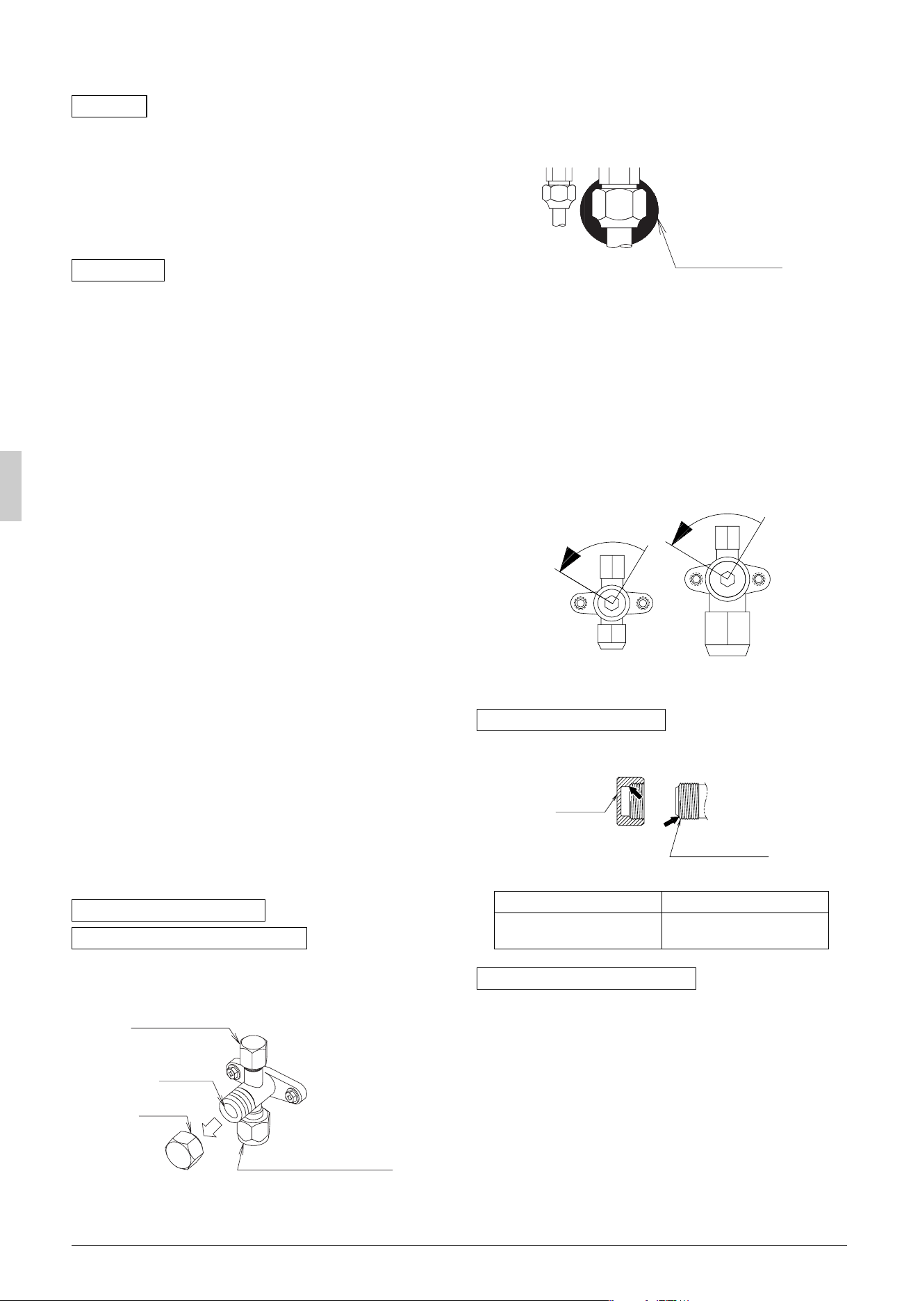
• The names of parts needed to operate the stop valve are shown
in the figure below. The unit is shipped from the factory with the
stop valve turned to the “closed” position.
• Since the side boards may be deformed if only a torque wrench is
used when loosening or tightening flare nuts, always lock the stop
valve with a wrench and then use a torque wrench.
• In cases where the unit is run in heating mode when the outside
temperature is low or in other situations where the operating pres-
sure might drop, seal the gas-side flare nut on the stop valve with
silicon sealant or the like to prevent it from freezing.
Stop valve operation procedure
Have a hexagonal wrench ready (size: 0.2 inch and 0.3 inch / 4 mm
and 6 mm).
Opening the valve
1.
Place the hexagonal wrench on the valve bar and turn counter-
clockwise.
2.
Stop when the valve bar no longer turns. It is now open.
Close the valve
1.
Place the hexagonal wrench on the valve bar and turn clockwise.
2.
Stop when the valve bar no longer turns. It is now closed.
• A seal is attached to the point indicated by the arrow.
Take care not to damage it.
• Be sure to tighten the valve lid securely after operating the valves.
• Use a push-rod-provided charging hose for operation.
• Be sure to tighten the valve lid securely after operation.
Tightening torque .......... 8.5-10.3 ft·lbf (11.5-14.0 N·m)
Air tight test
Vacuum drying
Stop valve operation procedure
Precautions when handling the stop valve
Servicing port
Valve bar
Valve lid
Inter-unit piping connection
Precautions for handling valve lid
Liquid-side tightening torque Gas-side tightening torque
10.0-12.2 ft·lbf
(13.5-16.5 N·m)
16.6-20.3 ft·lbf
(22.5-27.5 N·m)
Precautions for handling servicing port
Silicon sealing pad
(Make sure that there is no gap)
Direction to open Direction to open
<Gas pipe><Liquid pipe>
Valve lid
Stop valve
(lid attachment)
01_EN_3P329623-1.fm Page 11 Friday, November 9, 2012 6:50 PM
English 12
8. ADDITIONAL REFRIGERANT CHARGE
WARNING
• When leaving the unit with the power on, be sure to
switch with another person doing the installation or
close the front panel.
8-1 Before adding refrigerant
• Make sure the following work and inspection is complete, in
accordance with the installation manual.
•Piping
• Wiring
• Airtightness test, Vacuum drying
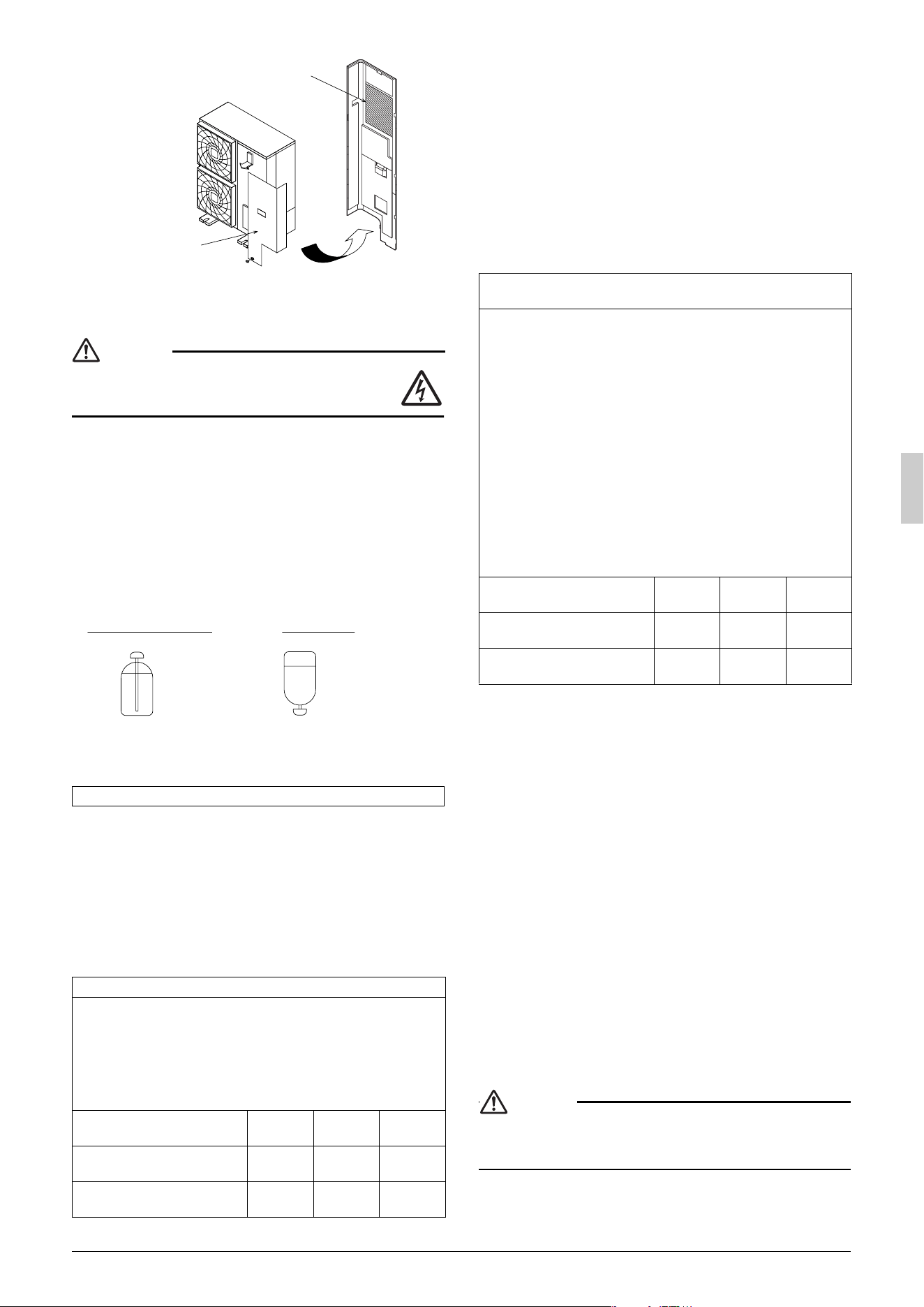
8-2 Checking the refrigerant tank
• Check whether the tank has a siphon pipe before charging and
place the tank so that the refrigerant is charged in liquid form.
(See the figure below.)
8-3 Adding refrigerant
1.
Calculate the amount of refrigerant to add as described in “Calcu-
lating the amount of refrigerant to add” in “7-7 Example of con-
nection (page 10)”.
2.
After the vacuum drying is finished, open valve A and charge the
calculated amount of refrigerant through the service port for the
liquid-side stop valve.
3.
Close valve A after charging is complete.
Note:If all the refrigerant to be added cannot be charged using the
above procedure, right-hand the procedure below and re-
charge the refrigerant.
If all the refrigerant could not be added
Add refrigerant using the following procedure. See the “Cautions on
Service” plate on the back of the front panel for details on the set-
tings for adding refrigerant.
[Procedure]
1.
Close the front panel and turn on the power to all outdoor units
and indoor units in the refrigeration system.
2.
Open the gas and liquid-side stop valve all the way and add the
refrigerant. (Open valve A immediately after starting the compres-
sor.)
3.
Once the appropriate amount of refrigerant is in, press the confir-
mation button (BS3) on the outdoor unit PC board (A2P), and stop
operation after adding the refrigerant.
4.
Close valve A after charging is complete.
9. POST-WORK CHECKS
Perform the following checks after work is complete.
(1) Drain pipe connection, removal of transport clasp →
See “5. PRECAUTIONS ON INSTALLATION (page 6)”.
(2) Incorrect power supply wiring, loose screws →
See “6-3 How to connect the power supply wiring (page 7)”.
(3) Incorrect inter-unit wiring, loose screws →
See “6-4 Inter-unit wiring connection procedure (page 8)”.
(4) Incorrect refrigerant piping connections →
See “7. PRECAUTIONS ON REFRIGERANT PIPING (page 8)”.
(5) Piping sizes, use of insulation →
See : “7-2 Selecting piping material (page 8)”.
“7-6 Heat insulation of piping (page 9)”.
(6) Stop valve check →
Make sure both the liquid-side and gas-side stop valves are
open.
(7) Record of Amount of Refrigerant Added →
Record it on “Recording the additionally charged refrigerant
quantity” on the “Cautions on Service” plate.
(8) Measuring the insulation of the main power circuit →
• Use a 500V mega-tester.
• Do not use the mega-tester for weak currents other than 208/
230V. (Inter-unit wiring)
CAUTION
To the pipe-layer
After completing installation, be sure to open the valve.
(Operating the unit with the valve shut will break the compressor.)
Filling after calculating the amount of refrigerant to add
Status of the stop valve and other valves when adding refrigerant
•
See “Stop valve operation procedure” in “7-8 Air tight test and
vacuum drying (page 11)” for details on how to use the stop valve.
(Refer to figure 28)
1. R410A Tank (Siphon system) 5. Stop valve service port
2. Measuring instrument 6. Gas line stop valve
3. Valve A 7.Outdoor unit
4. BP unit 8.Liquid line stop valve
State of valve A and the stop
valve
Valve A
Liquid line
stop valve
Gas line
stop valve
Before starting to charge the
refrigerant
Close Close Close
During charging of the refrig-
erant
Open Close Close
Location of “Cautions on Service” plate.
The back of front panel
Front panel
Tank with siphon pipe Other tanks
There is a siphon
pipe inside, so the
cylinder need not be
upside-down to fill
with liquid.
(Stand the cylinder
upright when filling.)
Stand the tank
upside down and
charge.
Status of the stop valve and other valves when adding refrigerant
operation
• See “Stop valve operation procedure” in “7-8 Air tight test and
vacuum drying (page 11)” for details on how to use the stop
valve.
• Connect the service port (for charging refrigerant) inside the
unit. When the unit is shipped from the factory, refrigerant is
already charged, so be careful when connecting the charge
hose.
• After adding the refrigerant, do not forget to close the lid of the
service port (for adding refrigerant). The tightening torque of the
lid is 8.5-10.3 ft·lbf (11.5-14.0 N·m)
(Refer to figure 29)
1. Gas line stop valve 2. Liquid line stop valve
3. Stop valve service port 4. BP unit
5. Measuring instrument 6. R410A Tank (Siphon
system)
7. Valve A 8. Service port
9.(For adding refrigerant) 10.Outdoor unit
State of valve A and the stop
valve
Valve A
Liquid line
stop valve
Gas line
stop valve
Before starting to charge the
refrigerant
Close Open Open
During charging of the refrig-
erant
Open Open Open
01_EN_3P329623-1.fm Page 12 Friday, November 9, 2012 6:50 PM

13 English
10. TEST RUN
This unit is equipped with a crank case heater to ensure smooth
startup. Be sure to turn the power on at least 6 hours before
operation in order to have power running to the crank case
heater.
WARNING
When leaving the unit with the power on, be sure to
switch with another person doing the installation or
close the front panel.
Precautions before turning the power on
• Using insulating sheets, tape electric parts as described in the
“Cautions on Service” plate on the back of the front panel.
• All indoor units connected to the outdoor unit operate automati-
cally.
Complete work on the indoor units in order to ensure maximum
safety.
10-1 Power On–Check Operation
• Make sure to perform the check operation after installation.
(If the air conditioner is operated using the indoor remote control-
ler without performing the check operation, the malfunction code
“U3” is displayed in the indoor remote controller, and normal oper-
ation is disabled.)
• When making settings on the outdoor unit PC board (A2P) after
turning the power on, do not touch anything other than the push-
button switches and dip switches.
(See the “Cautions on Service” plate for the locations of the
push-button switches (BS1-5) and dip switches (D1-1, 2) on the
PC board (A2P).)
• During the operation, monitor the outdoor unit operation status
and check for any incorrect wiring.
<Precautions During Check Operation>
• If operation is performed within 12 minutes of BP units and
outdoor units being turned on, H2P will light up, and the
compressor will not run.
Only perform operation after checking that the LED display is as
shown in “10-1 Power On–Check Operation” 2. table.
• In order to ensure uniform refrigerant distribution, it may take up to
around 10 minutes for the compressor to start up after the unit
begins running. This is not a malfunction.
• Each indoor unit cannot be checked individually for problems.
After this operation is complete, run the unit normally using the
remote controller.
• The check run cannot be performed in recovery or other modes.
• If the outlet pipe thermistor (R2T), the intake pipe thermistor
(R3T), and the pressure sensors (S1NPH and S1NPL) are
removed before operation, the compressor might burn out, so
avoid this under all circumstances.
10-2 Temperature control operation checklist
• After check operation is complete, checking the temperature con-
trol using normal operation.
(Heating is not possible if the outdoor temperature is 75°F (24°C)
or higher. See the included operation manual.)
(1) Make sure the indoor and outdoor units are operating nor-
mally.
(If liquid compression by the compressor or other abnormal
noises can be heard, stop the unit immediately, heat the
crank case for a sufficient amount of time, and try again.)
(2) Run each indoor unit one at a time and make sure the corre-
sponding outdoor unit is also running.
(3) Check to see if cold (or hot) air is coming out of the indoor
unit.
(4) Press the fan direction and fan strength buttons on the indoor
unit to see if they operate properly.
<Precautions during temperature control checks>
• For around 5 minutes after the compressor stops, the compressor
will not run even if the “operate/stop” button on the remote control-
ler is pressed.
• When the system operation is stopped by the remote controller,
the outdoor units may continue operating for further 1 minutes at
maximum.
• Malfunction code “U3” is displayed if check operation is not per-
formed using the test run button the first time after installation.
Perform the check operation in accordance with “10-1 Power On–
Check Operation”.
[Indoor unit displays malfunction sign]
(Check on a remote controller connected to the indoor unit.
For details. see the operation manual which comes with indoor unit.
)
1. Close the outdoor unit’s front panel.
Turn the power on for the outdoor
unit and the BP unit.
2.
•
Open the outdoor unit’s front panel.
•
Make sure the LED display on the outdoor unit’s PC boards (A1P and
A2P) are as shown in the following chart.
LED display
(Default status
before delivery)
SEVICE
MONITOR
MODE
HAP
A1P A2P
H1P H2P H3P H4P H5P H6P H7P
TEST/
HWL
IND
MASTER
SLAVE
L.N.O.P
DEMAND
6. Close the outer panel of the outdoor unit after check operation is complete.
Do not leave any stop valve closed
otherwise the compressor will fail.
Caution
Be sure to turn the power on at least
6 hours before operation in order to have
power running to the crank case heater.
To avoid the risk of electric shock, do not touch anything other than the
push-button switches on the PC board (A2P) when making settings.
Caution
LED display: OFF ON Blinking
Use caution to avoid electric shock while
working, since the outdoor unit is on.
•
Only set the push-button switches (BS1-5)
after making sure the microcomputer OK
monitor is lit up.
•
See the “Cautions on Service” plate on the
front panel of the outdoor unit for details on
how to make the settings.
(Do not forget to write the settings down on
the “Cautions on Service” plate.)
•
The dip switch (DS1-1) does not need to be
set, so do not touch it.
Doing so may cause malfunction.
• If you have to leave the outdoor unit during
check operation, either switch with another
worker or close the front panel.
• The system operates for about 30 minutes (60
minutes at maximum) and automatically stops
the check operation.
• The system can start normal operation about
3 minutes after the check operation if the
remote controller does not display any error
code.
3.
•
When the customer requests
quiet operation or demand
operation, make these settings
using the push-button switches
(BS1-5) on the outdoor unit’s
PC board (A2P).
•
Operate the push-button
switches through the opening
after protecting it with an
insulation cover.
(See the “Cautions on Service”
plate for details.)
4.
•
Check that the liquid and gas-side
stop valves are open, and if
they are closed, open them.
5. Press the test run button (BS4) for
at least 5 seconds and perform
check operation.
For details, see “check operation
procedure” on the “Cautions on
Service” plate.
Malfunc-
tion code
Installation error Remedial action
E3
The stop valve of an out-
door unit is left closed.
Open the gas-side stop valve and the
liquid-side stop valve.
Refrigerant overcharge.
Recalculate the required amount of
refrigerant from the piping length and
correct the refrigerant charge level by
recovering any excessive refrigerant
with a refrigerant recovery machine.
E4
The stop valve of an out-
door unit is left closed.
Open the gas-side stop valve and the
liquid-side stop valve.
Insufficient refrigerant.
Check if the additional refrigerant
charge has been finished correctly.
Recalculate the required amount of
refrigerant from the piping length and
add an adequate amount of refrigerant.
F3
Refrigerant overcharge.
Recalculate the required amount of
refrigerant from the piping length and
correct the refrigerant charge level by
recovering any excessive refrigerant
with a refrigerant recovery machine.
The stop valve of an outdoor
unit is left closed.
Open the gas-side stop valve and the
liquid-side stop valve.
Insufficient refrigerant.
Check if the additional refrigerant
charge has been finished correctly.
Recalculate the required amount of
refrigerant from the piping length and
add an adequate amount of refrigerant.
01_EN_3P329623-1.fm Page 13 Friday, November 9, 2012 6:50 PM
English 14
• When using a central controller, see the installation manual or
service manual which came with the central controller.
CAUTION
To the pipe-layer, To the electrician
After the test run, when handing the unit over to the customer,
make sure the front panel on the unit and all screws are attached.
11. CAUTION FOR REFRIGERANT LEAKS
(Points to note in connection with refrigerant leaks)
Introduction
The installer and system specialist shall secure safety against
leakage according to local regulations or standards. The follow-
ing standards may be applicable if local regulations are not
available.
This system uses R410A as refrigerant. R410A itself is an entirely
safe non-toxic, non-combustible refrigerant. Nevertheless care must
be taken to ensure that air conditioning facilities are installed in a
room which is sufficiently large. This assures that the maximum con-
centration level of refrigerant gas is not exceeded, in the unlikely
event of major leak in the system and this in accordance to the local
applicable regulations and standards.
Maximum concentration level
The maximum charge of refrigerant and the calculation of the maxi-
mum concentration of refrigerant is directly related to the humanly
occupied space in to which it could leak.
The unit of measurement of the concentration is lb./ft
3
(kg/m
3
) (the
weight in lb. (kg) of the refrigerant gas in 1 ft
3
(0.028 m
3
) volume of the
occupied space).
Compliance to the local applicable regulations and standards for the
maximum allowable concentration level is required.
Pay a special attention to the place, such as a basement, etc.
where refrigerant can stay, since refrigerant is heavier than air.
Procedure for checking maximum concentration
Check the maximum concentration level in accordance with steps 1
to 4 below and take whatever action is necessary to comply.
1. Calculate the amount of refrigerant (lb. / kg) charged to each sys-
tem separately.
Note
• Where a single refrigerant facility is divided into 2 entirely inde-
pendent refrigerant systems then use the amount of refrigerant
with which each separate system is charged.
2. Calculate the smallest room volume (ft
3
/m
3
)
Incase like the following, calculate the volume of (A), (B) as a sin-
gle room or as the smallest room.
A.
Where there are no smaller room divisions
B.
Where there is a room division but there is an opening
between the rooms sufficiently large to permit a free flow of
air back and forth.
(Where there is an opening without a door or where there are
openings above and below the door which are each equivalent in
size to 0.15% or more of the floor area.)
3. Calculating the refrigerant density using the results of the calcu-
lations in steps 1 and 2 above.
If the result of the above calculation exceeds the maximum con-
centration level then make similar calculations for the second then
third smallest room and so until the result falls short of the maxi-
mum concentration.
4. Dealing with the situations where the result exceeds the maxi-
mum concentration level.
Where the installation of a facility results in a concentration in
excess of the maximum concentration level then it will be neces-
sary to revise the system.
Please consult your Daikin supplier.
U2
Insufficient supply voltage
Check to see if the supply voltage is
supplied properly.
U3
If a check operation has not
been performed.
Perform a check operation.
U4
No power is supplied to an
outdoor unit.
Turn the power on for the outdoor unit.
UA
If no dedicated indoor unit is
being used.
Check the indoor unit. If it is not a ded-
icated unit, replace the indoor unit.
UF
The stop valve of an out-
door unit is left closed.
Open the gas-side stop valve and the
liquid-side stop valve.
If the right indoor unit piping
and wiring are not properly
connected to the outdoor
unit.
Make sure that the right indoor unit
piping and wiring are properly con-
nected to the outdoor unit.
UH
If the inter-unit wiring has
not be connected or it has
shorted.
Make sure the inter-unit wiring is cor-
rectly attached to terminals (X2M) F1/
F2 (To BP unit) on the outdoor unit cir-
cuit board.
Direction of the refrigerant flow
BP unit
Room where
refrigerant leak
has occurred
(outflow of all the
refrigerant from
the system)
amount of refriger-
ant in a single unit
system (amount of
refrigerant with
which the system
is charged before
leaving the factory)
+
additional charging
amount (amount of
refrigerant added
locally in accordance
with the length or
diameter of the refrig-
erant piping)
=
total amount
of refriger-
ant (lb. / kg)
in the system
total volume of refrigerant in the
refrigerant system
≤
maximum concen-
tration level (lb./ft
3
/
kg/m
3
)
size (ft
3
/ m
3
) of smallest room in
which there is an indoor unit
installed
BP unit
Opening
between rooms
Partition
BP unit
01_EN_3P329623-1.fm Page 14 Friday, November 9, 2012 6:50 PM
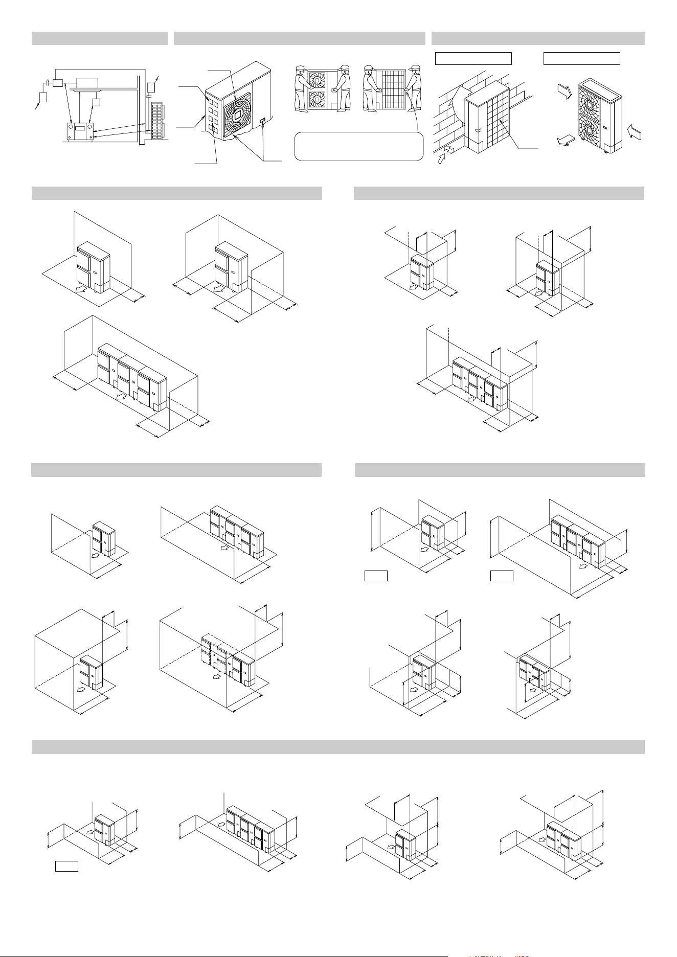
figure 1
2
3
4
5
2
1
≥40 (1,000)
≥40 (1,000)
≥60 (1,500)
≥60 (1,500)
≥60 (1,500)
unit : inch (mm)
[1]
[2]
[3]
4 (100) or more
4 (100) or more
12 (300) or more
4 (100) or more
4 (100) or more
8 (200) or more
4 (100) or more
unit : inch (mm)
figure 4
figure 7
1
2
4
5
67
8
3
figure 2
1
2
3
4
5
6
5
figure 3
[1]
[2]
[3]
4 (100) or more
6 (150) or more
20 (500)
or more
40 (1,000)
or more
6 (150)
or more
6 (150)
or more
40 (1,000)
or more
20 (500)
or more
unit : inch (mm)
20 (500)
or more
40 (1,000)
or more
40 (1,000)
or more
8 (200)
or more
12 (300) or more
figure 5
[1]
[2]
[3]
[4]
20 (500) or more
20 (500)
or more
20 (500)
or more
20 (500)
or more
40 (1,000)
or more
40 (1,000) or more
40 (1,000)
or more
40 (1,000)
or more
unit : inch (mm)
figure 6
[1]
[2]
L
L
L
AA
L
H
H
H
H
20 (500)
or more
10 (250)
or more
12 (300)
or more
20 (500)
or less
20 (500)
or less
4 (100)
or more
12 (300)
or more
40 (1,000)
or more
L > HL > H
[3]
[4]
40 (1,000)
or more 40 (1,000)
or more
unit : inch (mm)
figure 7
[5]
[6]
[7]
[8]
L
L
L
L
H
H
H
H
A
A
A
20 (500)
or more
20 (500)
or more
20 (500)
or more
4 (100)
or more
60 (1,500)
or more
40 (1,000)
or more
60 (1,500)
or more
40 (1,000)
or more
40 (1,000)
or more
L > H
unit : inch (mm) unit : inch (mm)
00_CV_3P329623-1.fm Page 2 Friday, November 9, 2012 6:43 PM
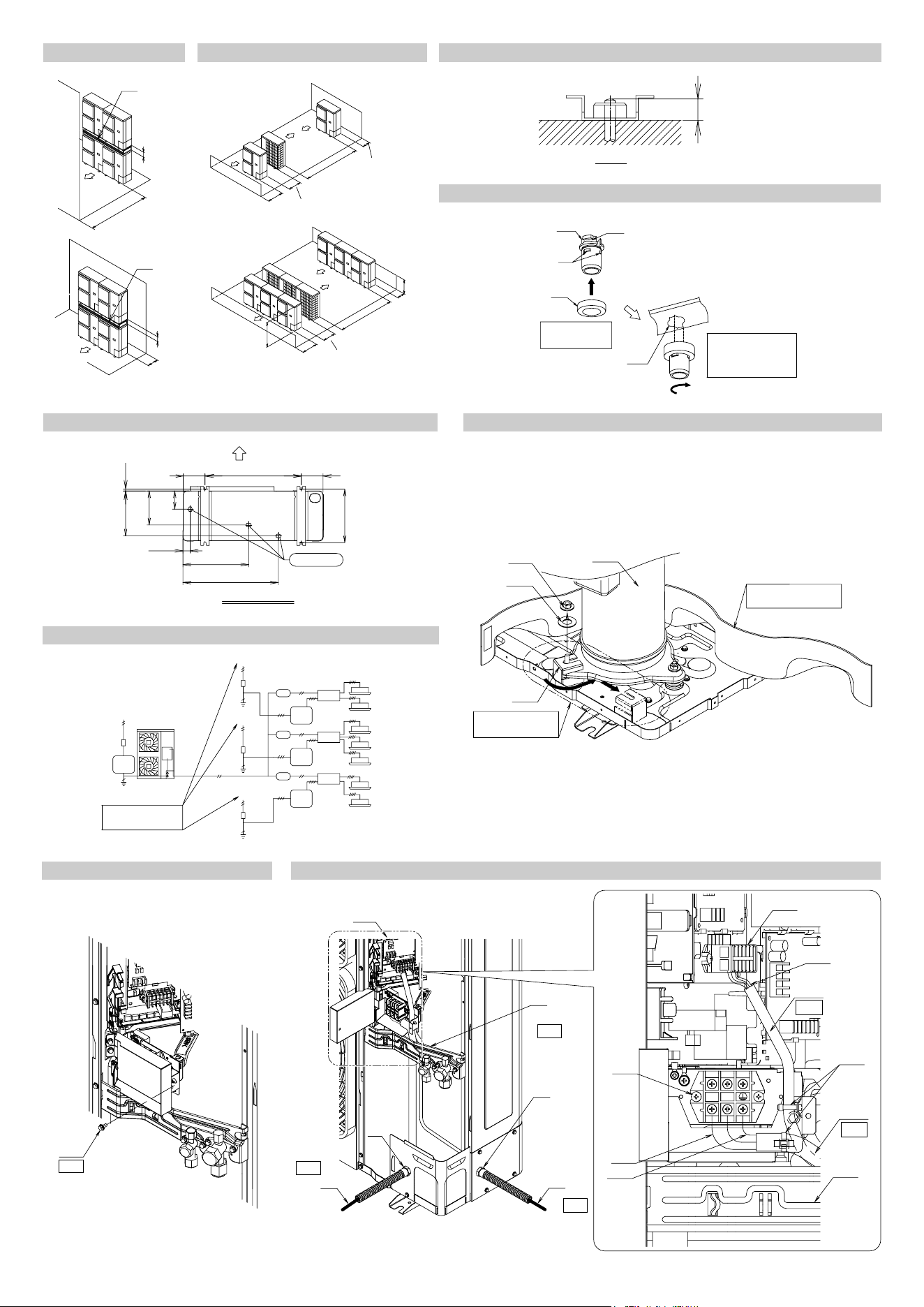
[1]
[2]
Z
Z
40 (1,000)
or more
12 (300)
or more
4 (100)
4 (100)
figure 8 figure 9
1
2
figure 16
7
1
4
3
4
22
5
6
L2
L1
17
8
13
14
16
9
17
15
12
10
11
1
[1]
[2]
40 (1,000)
or more
80 (2,000)
or more
8 (200)
or more
24 (600)
or more
4 (100)
or more
60 (1,500)
or more
120 (3,000)
or more
H
A
L
unit : inch (mm)
1
15/16 (20)
unit : inch (mm)
figure 10
1
2
7
3
4
6
5
1
2
3
5-1/2 (140)
5-1/2 (140)
16-5/8 (421)
1-3/4 (45)
24-1/8 (612)
24-3/8 (140)
13-3/4 (350)
8-5/8 (219)
4-5/8 (117)
1-3/16 (30)11-7/16 (290)
13-5/8-14
(345-355)
unit : inch (mm)
1
2
3
4
5
6
7
3
3
2
2
4
8
8
8
7
7
7
7
7
7
7
5
6
6
6
6
5
5
9
9
1
3
2
9
3
2
9
figure 12
figure 11
figure 14
figure 15
figure 13
00_CV_3P329623-1.fm Page 3 Friday, November 9, 2012 6:43 PM
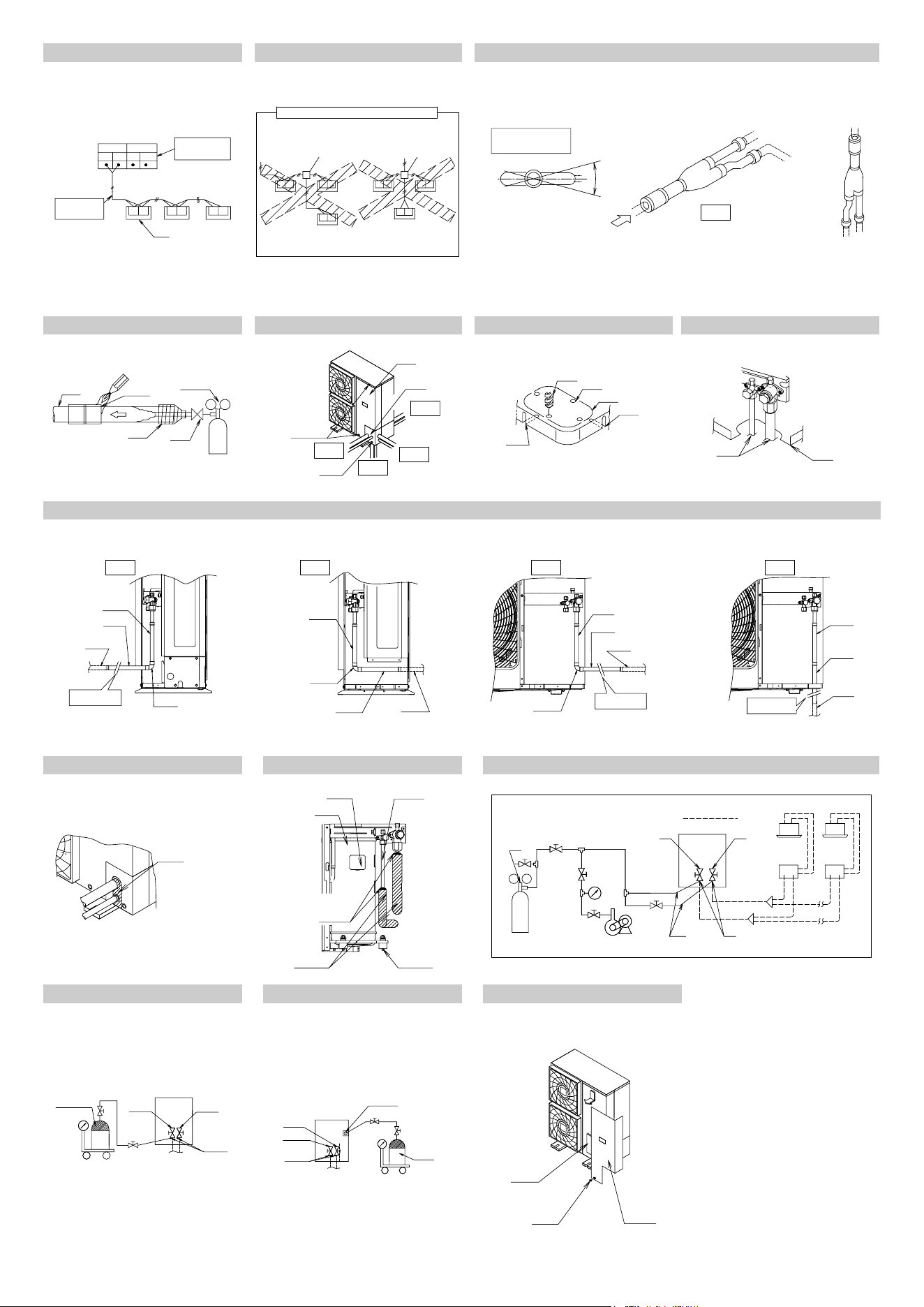
F1 F2
F1
TO BP UNIT
TO OUT/D UNIT
F2 F1 F2
F1 F2 F1 F2
1
2
3
4
1
2
3
5
6
8
4
7
[1]
[2]
[3]
[4]
1
2
2
2
2
3
3
4
5
4
5
6
3
3
4
4
6
5
5
1 1 1
figure 24
1
2
3
4
5
6
7
8
figure 28
1
2
3
4
4
5
6
figure 29
figure 20
figure 30
11
2
3
F1F2
F1F2
F1F2 F1F2F1F2F1F2
figure 17 figure 18
1
2
3
4
5
6
A
figure 19
1
2
3
4
4
1
2
figure 21 figure 22 figure 23
1
2
1
2
3
4
5
6
1
2
3
4
56
77
11
12 12
10
89
figure 25 figure 26 figure 27
10
1
2
3
4
5
6
7
8
9
1
2
3
00_CV_3P329623-1.fm Page 4 Friday, November 9, 2012 6:43 PM
HT
Two-dimensional bar code is a code
for manufacturing.
3P329623-1
M12B276
(1211)
00_CV_3P329623-1.fm Page 5 Friday, November 9, 2012 6:43 PM