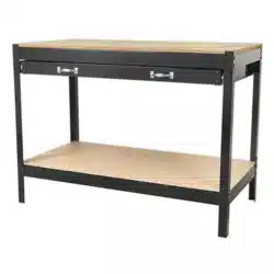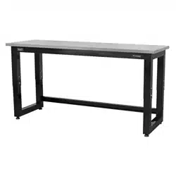
1830MM HEAVY-DUTY STEEL ADJUSTABLE
WORKBENCH WITH WOODEN OR STAINLESS
STEEL WORKTOP
MODEL NO: APMS22, APMS23
Thank you for purchasing a Sealey product. Manufactured to a high standard, this product will, if used according to these
instructions, and properly maintained, give you years of trouble free performance.
I
MP
PO
R
RTA
TA
NT:
PLEA
S
E READ THE
S
E IN
S
TRU
C
TI
O
N
S
C
AREFULLY. N
O
TE THE
S
AFE
O
PERATI
O
NAL RE
Q
UIREMENT
S
, WARNIN
GS
&
C
AUTI
O
N
S
. U
S
E
TH
HE
P
PR
O
ODU
C
T
CO
RRE
C
TLY AND WITH
C
ARE F
O
R THE P
U
RP
OS
E F
O
R WHI
C
H IT I
S
INTENDED. FAIL
U
RE T
O
D
O
SO
MAY
C
A
US
E DAMA
G
E AND
/O
R
PE
ER
S
SON
N
AL IN
JU
RY AND WILL INVALIDATE THE WARRANTY. KEEP TH
ESE
IN
STR
UCT
ION
S S
AFE
FO
R F
U
T
U
RE
USE
.
1. SAFETY
WARNING! Ensure Health & Safety, local authority and general workshop practice regulations are adhered to when using this
bench.
Locate the bench in a suitable work area.
Keep the work area clean, uncluttered and ensure there is adequate lighting.
WARNING! Use the bench on level and solid ground, preferably concrete.
Keep the bench clean and tidy in accordance with good workshop practice.
Keep children and unauthorised persons away from the work area.
DO NOT use the bench for any purpose other than which it is designed.
DO NOT undertake work on the bench without the workpiece being adequately secured.
DO NOT use the bench outdoors.
DO NOT get the bench wet or use in damp or wet locations or areas where there is condensation.
DO NOT clean the bench with any solvents which may damage the surface or the protective coating on the worktop.
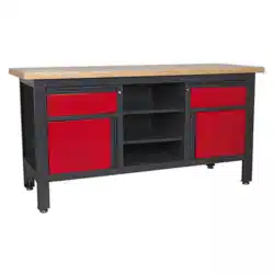
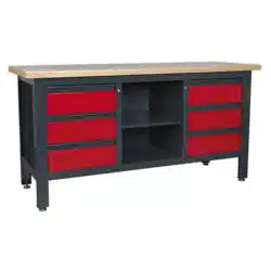
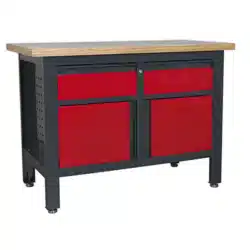
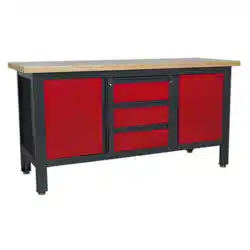
2. INTRODUCTION
Manufactured from heavy gauge powder-coated steel and is at the top end of our range with a weight capacity of 1000kg (evenly distributed).
Adjustable leg extensions allow worktop height to range from 680 to 1030mm. Fitted with adjustable feet to ensure work surface is level,
even if your fl oor is not. Durable 32mm thick solid wood worktop (APMS22), stainless steel worktop (APMS23).
3. SPECIFICATION
Model No: ................................................ APMS22, APMS23
Size (W x D x H): ...................... 1830 x 610 x (680-1030)mm
Work top:
APMS22 ................................................................ Solid wood
APMS23 .......................................................... Stainless steel
4. CONTENTS
APMS22, APMS23 Issue 1 09/08/21
Original Language Version
© Jack Sealey Limited
Refer to
instructions
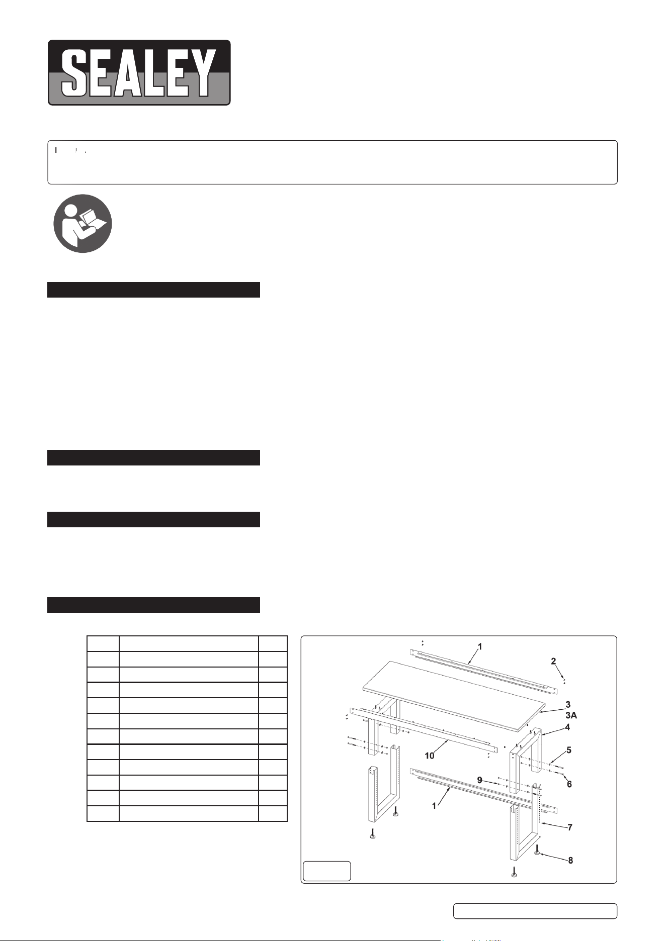
ITEM DESCRIPTION QTY
1 Back stiffener 2
2 M6 x 16 Hex socket head screw 30
3 Solid wood top 1
3A Stainless steel top 1
4 Upper supporting frame 2
5 M8 Flat washer 16
6 M8 x 85 hex bolt 8
7 Bottom support frame 2
8 Adjustable foot 4
9 M8 hex nut 8
10 Front stiffener 1
fi g.1
5. ASSEMBLY
Unpack the product and check contents against the contents diagram (section 4.0) prior to assembly. Should there be any
damaged or missing parts contact your supplier immediately.
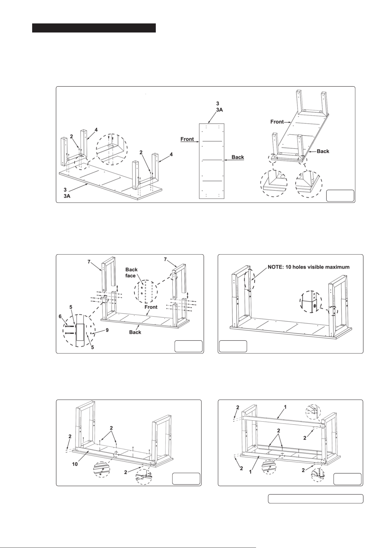
5.1. ATTACHING THE UPPER SUPPORT FRAMES
5.1.1. Place the work top (fi g 2 - 3 & 3A) top face down onto a protected fl oor surface (use original packaging).
5.1.2. Align the fi xing holes in the upper support frames (fi g 2 - 4) with the corresponding holes on the work top and secure with M6 x 16
hex socket head screws (fi g 2 - 2).
5.2. ATTACHING THE BOTTOM SUPPORT FRAMES
5.2.1. Insert the bottom support frame (fi g 3 - 7) into the square opening of the upper support frame (fi g 2 - 4).
5.2.2. Determine the desired height required and secure with M8 x 85 hex bolt (fi g 3 - 6), M8 washers (fi g 3 - 5) and M8 hex nut (fi g 3 - 9).
5.2.3. Repeat for other side.
NOTE: The bottom support frame (fig 3 - 7) can be adjusted in 25mm increments, to give an overall working height of between 680
and 1030mm (fig 4), with a maximum of 10 visible holes (fig 4).
5.3. ATTACHING THE FRONT STIFFENER
5.3.1. Position the front stiff ener (fi g 5 - 10) to the front face, top level of the work bench part assembly.
5.3.2. Secure with M6 x 16 hex socket head screws (fi g 5 - 2).
5.4. ATTACHING THE BACK STIFFENERS
5.4.1. Position the back stiff eners (fi g 6 - 1) to the back face, top and bottom levels of the work bench part assembly.
5.4.2. Secure with M6 x 16 hex socket head screws (fi g 6 - 2).
APMS22, APMS23 Issue 1 09/08/21
Original Language Version
© Jack Sealey Limited
fi g.2
fi g.3 fi g.4
fi g.5
fi g.6
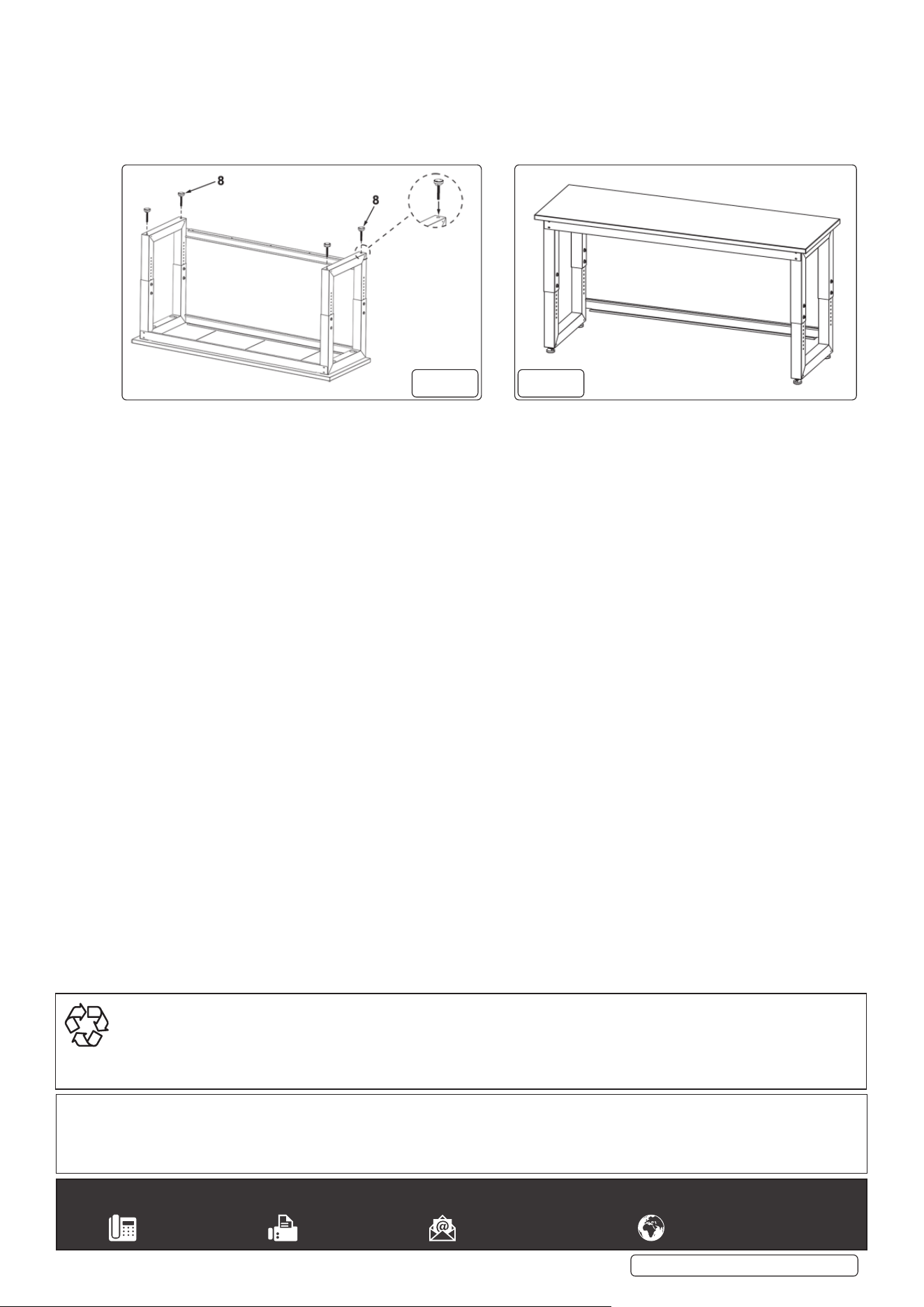
5.5. FITTING THE ADJUSTABLE FEET
5.5.1. Screw the adjustable feet (fi g 7 - 8) into the threaded holes in the bottom supporting frames.
5.6. LEVELLING THE WORKBENCH
5.6.1. With the assistance of another person turn the workbench over onto its adjustable feet (fi g - 8).
5.6.2. Place the workbench in the desired location and using a good quality spirit level adjust the feet as necessary to ensure that the
workbench is level and stable.
APMS22, APMS23 Issue 1 09/08/21
Original Language Version
© Jack Sealey Limited
Sealey Group, Kempson Way, Suffolk Business Park, Bury St Edmunds, Suffolk. IP32 7AR
01284 757500 01284 703534 sales@sealey.co.uk www.sealey.co.uk
ENVIRONMENT PROTECTION
Recycle unwanted materials instead of disposing of them as waste. All tools, accessories and packaging should be sorted, taken to
a recycling centre and disposed of in a manner which is compatible with the environment. When the product becomes completely
unserviceable and requires disposal, drain any fluids (if applicable) into approved containers and dispose of the product and fluids
according to local regulations.
Note: It is our policy to continually improve products and as such we reserve the right to alter data, specifications and component parts without prior
notice.
Important: No Liability is accepted for incorrect use of this product.
Warranty: Guarantee is 12 months from purchase date, proof of which is required for any claim.
fi g.7 fi g.8