Loading ...
Loading ...
Loading ...
Rinnai 22 HW_CF OIM
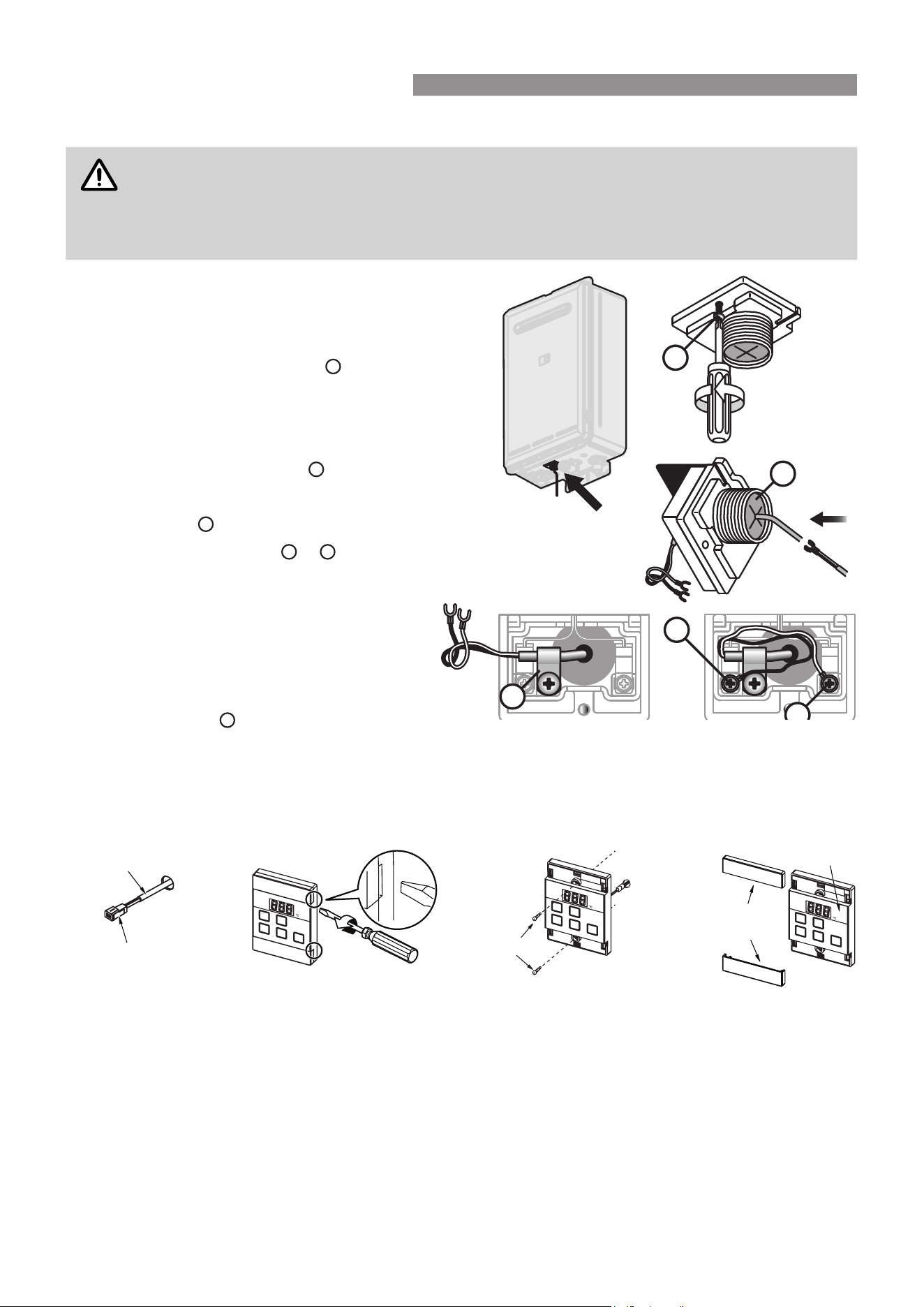
Communication Cable(s) & ’Ezi connect’
CAUTION
DO NOT attempt to connect cables to the 'Ezi connect' cable connector at the water heater
unless the electric power to the water heater is switched ‘off’ otherwise damage to electrical
components may occur�
If your water heater is not tted with an 'Ezi connect' cable connector, installation must be
completed by a qualied and licensed trades person.
1� Isolate the electric power supply by switching
the power point off and removing the power
plug of the water heater from the electric power
socket�
2� Remove the retaining screw
A
of the 'Ezi
connect' cable connector at the base of the
appliance�
3� Swing the 'Ezi connect' cable connector door
open and thread the cable through the weather
seal of the cable access hole
B
in the direction
shown allowing sufcient cable length so that
the sheath of the cable can be secured with
cable clamp
C
�
4� Loosen screw terminals
D
&
E
and connect
the cable spade connectors to these terminals
and re-tighten�
Polarity is not important, either wire colour can
be connected to either terminal�
5� Return the 'Ezi connect' cable connector to
the original position taking care not to damage
cable wires in the process and replace the
retaining screw
A
�
UNIVERSAL WATER CONTROLLER (MC-601Q) INSTALLATION
1� Determine the most suitable position, refer "Location" on page 21�
2� Mark and drill 3 holes (mounting and cable access) refer to "Table 1. Appliance Dimensions" and "Diagram 1.
Dimensions" on page 26 for water controller dimensions�
3� When running cable through the access hole ensure the connector end of the cable is located nearest to the
water controller (Fig. 1).
4� Carefully remove the cover plates from the water controller, using a screw driver (Fig. 2).
5� Connect the cable to the water controller� Feed any excess cable lengths into the wall cavity to avoid the
pinching of cables between the wall and the water controller�
6� Fix the water controller to the wall using the appropriate xings (Fig. 3).
7� Remove protective lm from the water controller face and replace the cover plates (Fig. 4).
A
C
E
D
B
Connector
Controller Cable
Screws
Film
Fig� 1 Fig� 2 Fig� 3 Fig� 4
Cover
Plates
WATER CONTROLLER INSTALLATION
Loading ...
Loading ...
Loading ...