30202400 • 8/23
ENGLISH
FRANÇAIS
ESPAÑOL
Models / Modelos
911607 – Push
(SN 000101 +)
911609 – Self-Propelled with REFLEX™ Drive
(SN 000101 +)
911614 – Self-Propelled Dual Blade with REFLEX™ Drive
(SN 000101 +)
911608 – Self-Propelled
(SN 000101 +)
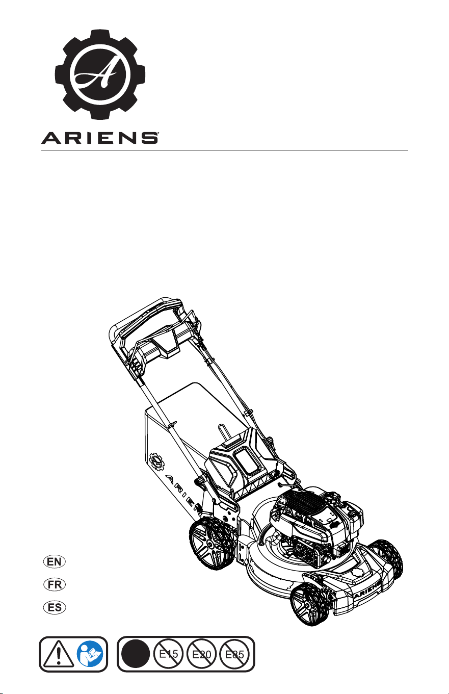
RAZOR
Operator’s Manual
Manuel du Utilisateur
Manual del operador
E10
®

WELCOME . . . . . . . . . . . . . . . . . . . . . . 1
Register Your Product!. . . . . . . . . . . . . . 1
SAFETY. . . . . . . . . . . . . . . . . . . . . . . . . 2
Practices and Laws . . . . . . . . . . . . . . . . 2
Emission Control System. . . . . . . . . . . . 2
Required Operator Training . . . . . . . . . . 2
Safety Alert Symbols . . . . . . . . . . . . . . . 2
Signal Words . . . . . . . . . . . . . . . . . . . . . 2
Safety Decals. . . . . . . . . . . . . . . . . . . . . 3
Safety Rules. . . . . . . . . . . . . . . . . . . . . . 4
ASSEMBLY. . . . . . . . . . . . . . . . . . . . . . 8
Package Contents . . . . . . . . . . . . . . . . . 8
Assembly . . . . . . . . . . . . . . . . . . . . . . . . 8
CONTROLS & FEATURES. . . . . . . . . . 9
Operator Presence Control (OPC) Lever 10
Rear Door . . . . . . . . . . . . . . . . . . . . . . . 10
Mulch Plug . . . . . . . . . . . . . . . . . . . . . . . 10
Grass Bag . . . . . . . . . . . . . . . . . . . . . . . 10
Handlebar . . . . . . . . . . . . . . . . . . . . . . . 10
Cutting Height-Adjustment Lever. . . . . . 10
Deck Washout Port . . . . . . . . . . . . . . . . 10
REFLEX Drive Handle . . . . . . . . . . . . . . 10
Wheel Drive Control Lever. . . . . . . . . . . 11
BEFORE OPERATION . . . . . . . . . . . . . 11
Empty Grass Bag. . . . . . . . . . . . . . . . . . 11
Prepare For Mowing . . . . . . . . . . . . . . . 11
Adjust Cutting Height . . . . . . . . . . . . . . . 13
Cutting Height Settings . . . . . . . . . . . . . 13
Adjust Handlebar Height . . . . . . . . . . . . 13
OPERATION . . . . . . . . . . . . . . . . . . . . . 14
Emergency Stopping . . . . . . . . . . . . . . . 14
Start the Engine . . . . . . . . . . . . . . . . . . . 14
Mow Grass. . . . . . . . . . . . . . . . . . . . . . . 14
Reverse mower . . . . . . . . . . . . . . . . . . . 14
Stop Engine . . . . . . . . . . . . . . . . . . . . . . 14
Mowing Tips. . . . . . . . . . . . . . . . . . . . . . 14
Mulching Tips. . . . . . . . . . . . . . . . . . . . . 14
MAINTENANCE . . . . . . . . . . . . . . . . . . 15
Maintenance Schedule . . . . . . . . . . . . . 15
Service Parts . . . . . . . . . . . . . . . . . . . . . 15
Service Position . . . . . . . . . . . . . . . . . . . 15
Check Engine Oil . . . . . . . . . . . . . . . . . . 16
Change Engine Oil. . . . . . . . . . . . . . . . . 16
Clean Engine Cooling Fins . . . . . . . . . . 16
Check Air Filter . . . . . . . . . . . . . . . . . . . 16
Clean Grass Bag . . . . . . . . . . . . . . . . . . 16
Wash Deck . . . . . . . . . . . . . . . . . . . . . . 16
Storage Position . . . . . . . . . . . . . . . . . . 17
Vertical Storage Position . . . . . . . . . . . . 17
Check Mower Blade(s) . . . . . . . . . . . . . 18
Check Drive Belt . . . . . . . . . . . . . . . . . . 20
Check Fasteners . . . . . . . . . . . . . . . . . . 20
Lubricate Unit. . . . . . . . . . . . . . . . . . . . . 20
SERVICE & ADJUSTMENTS . . . . . . . . 21
Adjust Wheel Drive Control Lever / REFLEX
Drive Handle . . . . . . . . . . . . . . . . . . . . 21
Adjust Operator Presence Control (OPC) Le-
ver . . . . . . . . . . . . . . . . . . . . . . . . . . . . 23
Replace Drive Belt . . . . . . . . . . . . . . . . . 23
TROUBLESHOOTING . . . . . . . . . . . . . 27
STORAGE . . . . . . . . . . . . . . . . . . . . . . . 28
Short-Term Storage . . . . . . . . . . . . . . . . 28
Long-Term Storage . . . . . . . . . . . . . . . . 28
Start-of-Season Fuel Preparation . . . . . 28
ACCESSORIES. . . . . . . . . . . . . . . . . . . 28
SPECIFICATIONS. . . . . . . . . . . . . . . . . 29
SPECIFICATIONS. . . . . . . . . . . . . . . . . 30
WARRANTY . . . . . . . . . . . . . . . . . . . . . 31
TABLE OF CONTENTS
EN - 1
© 2023 • AriensCo • Brillion, WI 54110
WELCOME
Congratulations on your purchase and welcome to the Ariens family! Every machine in the
Ariens lineup is designed for long-lasting and unsurpassed performance. We are confident your
machine will be part of your family for many years to come.
Have Questions or Need Assistance?
www.ariens.com
A parts manual for your unit is available for free download
or purchase at www.ariens.com.
REGISTER YOUR PRODUCT!
It is extremely important to register your
product at time of purchase. Product
registration activates the warranty and
establishes a communication link from
AriensCo.
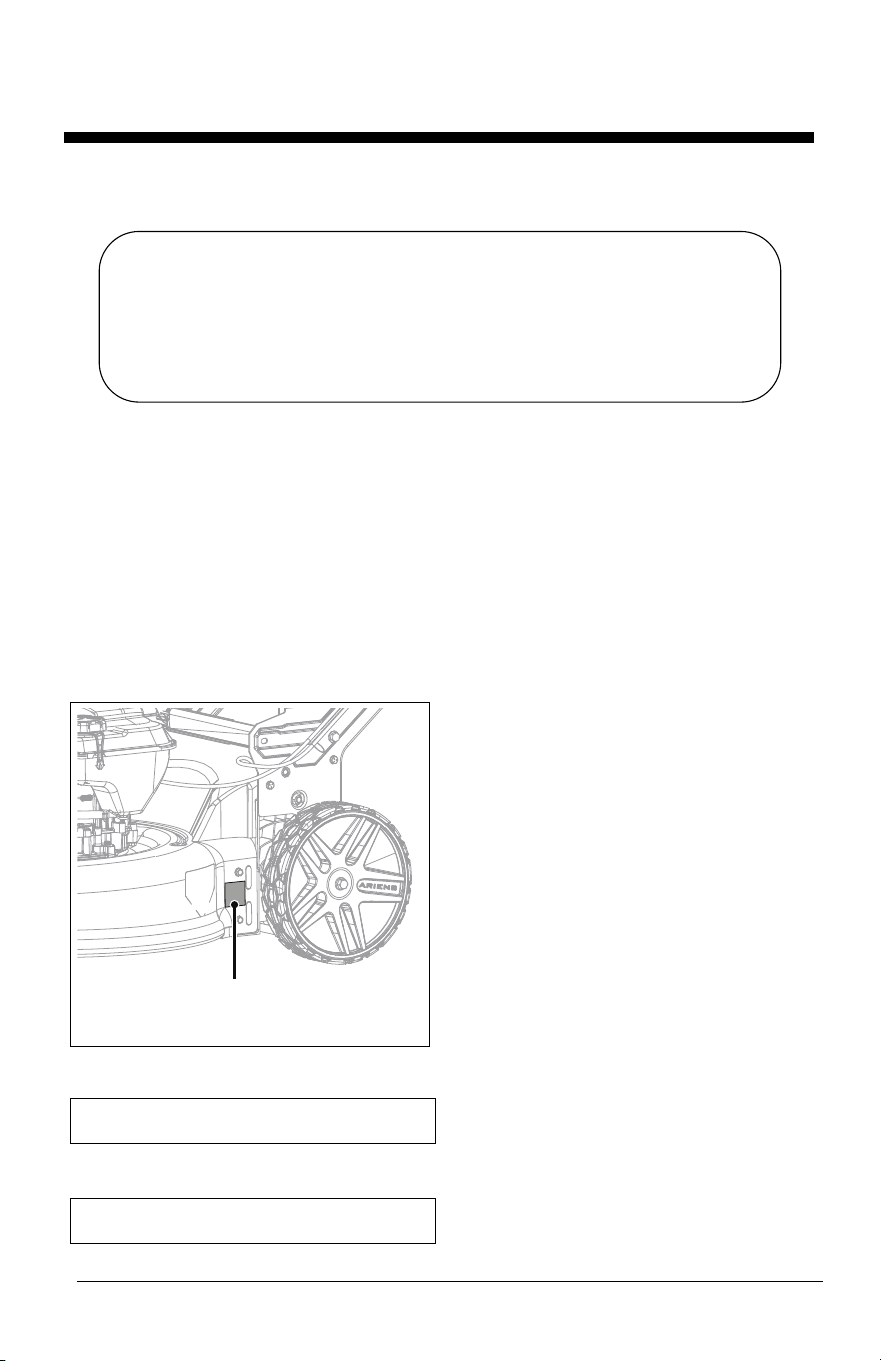
Locate the model and serial number decal on
your unit and register those numbers online at
www.ariens.com. See Figure 1 for decal
location. Be aware that the original selling
dealer may have already completed product
registration on behalf of the original
purchaser.
Record model number here.
Record serial number here.
Figure 1
Model & Serial Number Decal
MANUALS
Before operating or servicing the unit, carefully
and completely read the manuals provided with
the unit. They contain safety instructions and
important information about unit controls.
The engine on this unit is covered by a
separate manual. Refer to the engine manual
for engine service recommendations. Contact
the engine manufacturer for a replacement
manual if necessary.
Your dealer must review important information
in this manual with you before or upon delivery
of the unit. It is your responsibility to read and
understand all safety precautions and
instructions in the manuals. If you do not
understand or have difficulty following the
instructions, contact your Ariens dealer for
assistance. To locate your nearest Ariens
dealer, go to www.ariens.com.
DISCLAIMER
Ariens reserves the right to discontinue, make
changes to, and add improvements upon its
products at any time without public notice or
obligation. The descriptions and specifications
contained in this manual were in effect at
printing. Equipment described in this manual
may be optional. Some illustrations may not be
applicable to your unit.
EN - 2
Read these safety rules and follow them
closely. Failure to follow these rules could
lead to loss of control of unit, severe personal
injury or death to you or bystanders, or result
in damage to property or the machine.
PRACTICES AND LAWS
Practice usual and customary safe working
precautions. Learn applicable rules and laws
in your area. ALWAYS follow the practices set
forth in this manual.
EMISSION CONTROL SYSTEM
This equipment and/or its engine may include
exhaust and evaporative emissions control
system components required to meet U.S.
Environmental Protection Agency (EPA)
and/or California Air Resources Board
(CARB) regulations. Tampering with emission
controls and components by unauthorized
personnel may result in severe fines or
penalties. Emission controls and components
can only be adjusted by an Ariens Company
dealer or an authorized engine
manufacturer's service center. Contact your
Ariens Company Equipment Retailer
concerning emission controls and component
questions.
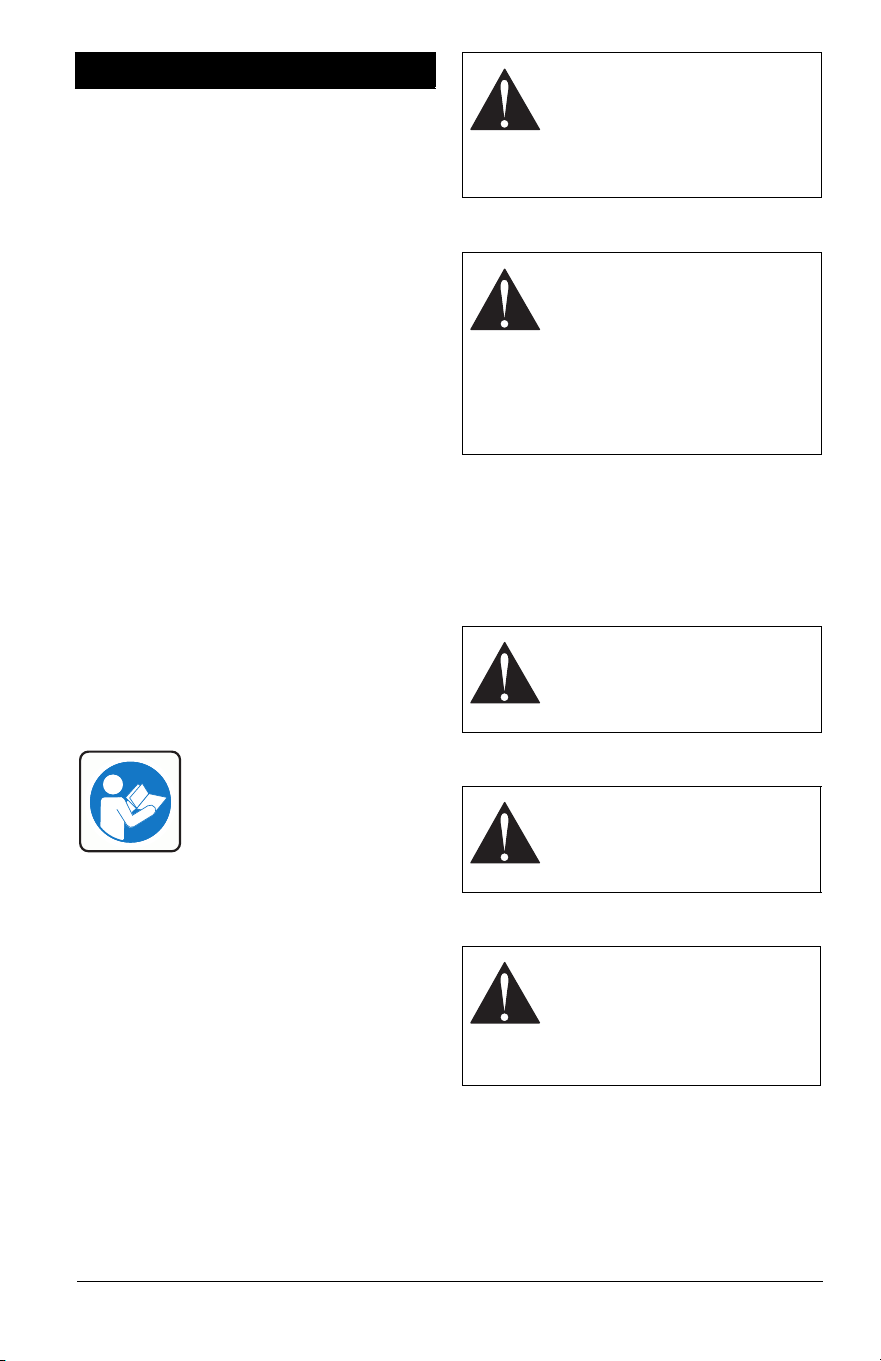
REQUIRED OPERATOR
TRAINING
Read and understand the
Operator's Manual and decals
on the unit. This information is
for your safety and the proper
use of your equipment.
Failure to follow these
instructions and warnings may cause death
or serious injury. If you have purchased this
product from an Ariens dealer, the dealer can
provide you with training.
Familiarize yourself and any other operators
with all controls and the safe use of the
features of this unit. If you loan, rent or sell
this product to others, provide them with all
manuals.
If you have any questions, please call our
customer support line at 920-756-4688 or
contact us at www.ariens.com. DO NOT use
this equipment if, after reading the Operator's
Manual and the on-board decals, you have
any questions about the safe use of this
product.
SAFETY ALERT SYMBOLS
SIGNAL WORDS
The safety alert symbol above and signal
words below are used on decals and in this
manual. Read and understand all safety
messages.
1. Danger
2. Warning
3. Caution
4. Notice
NOTICE: Indicates information or procedures
that are considered important but not hazard
related. If not followed, property damage
could result.
SAFETY
WARNING: This cutting machine
is capable of amputating hands
and feet and throwing objects.
Failure to observe the safety
instructions in the manuals and
on decals could result in serious
injury or death.
This is the safety alert symbol. It
means:
• ATTENTION!
• YOUR SAFETY IS
INVOLVED!
When you see this symbol:
• BECOME ALERT!
• OBEY THE MESSAGE!
DANGER: Indicates an
IMMINENTLY HAZARDOUS
SITUATION! If not avoided, WILL
RESULT in death or serious
injury.
WARNING: Indicates a
POTENTIALLY HAZARDOUS
SITUATION! If not avoided,
COULD RESULT in death or
serious injury.
CAUTION: Indicates a
POTENTIALLY HAZARDOUS
SITUATION! If not avoided, MAY
RESULT in minor or moderate
injury. It may also be used to alert
against unsafe practices.
EN - 3
5. Important
IMPORTANT: Indicates general reference
information worthy of special attention.
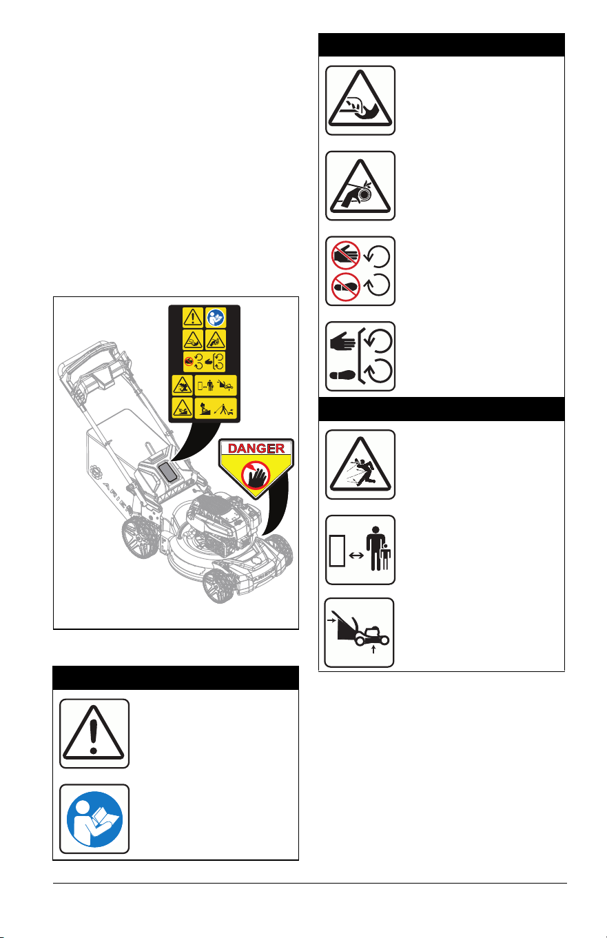
SAFETY DECALS
The safety decals on your machine are visual
reminders of the important safety information
in this manual. All messages on your unit
must be fully understood and carefully
followed. Safety decals on the machine are
explained below.
ALWAYS replace missing or damaged safety
decals. Replacement decal information is in
the parts manual for your machine. Decals
can be ordered from your dealer.
See Figure 2 for safety decal locations.
Safety Decal Identification
Safety Decal Description
1. DANGER!
DANGER!
Read and understand the
operator’s manual before
operating unit.
07800404
KEEP HANDS and FEET AWAY
0298
8
1
0
0
Figure 2
1
2
1.1 Amputation Hazard
To avoid amputation hazard
DO NOT put hands near
rotating blades.
To avoid amputation hazard
DO NOT put hands or feet
near moving belts.
Keep hands and feet away
from all rotating or moving
parts.
Keep all guards and shields
in place.
1.2 Discharge Hazard
Discharge Hazard – NEVER
direct discharge toward
people, pets or property.
Thrown objects can cause
injury or damage.
Keep children and others
away from unit while unit is
in operation.
DO NOT operate mower
unless guards are in
operating position or entire
bagger is attached.
EN - 4
SAFETY RULES
The following safety instructions are based
on the B71.1 specifications of the American
National Standards Institute and ISO 5395 in
effect at the time of production.
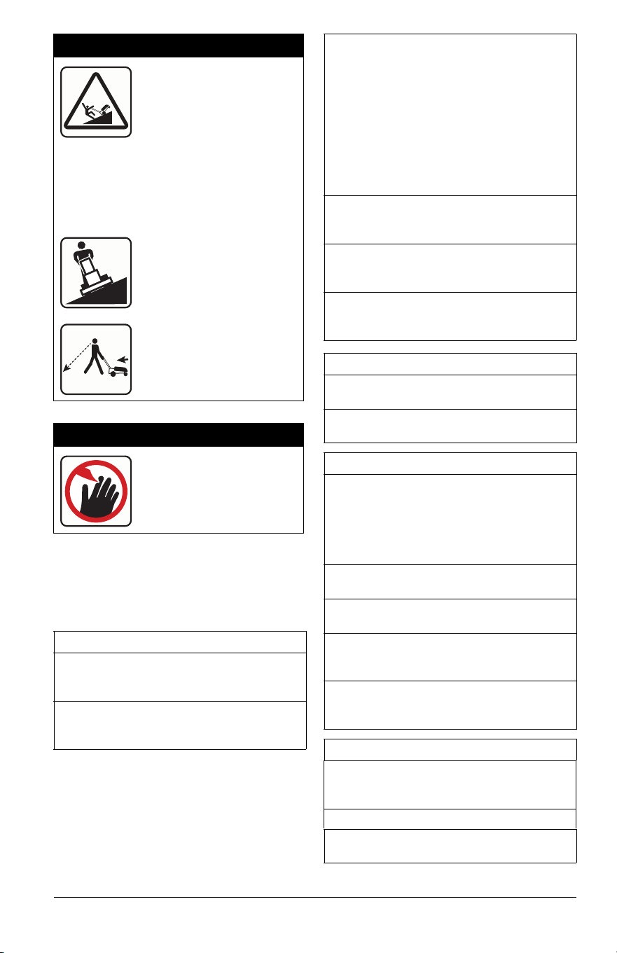
1.3 Tipping Hazard
SERIOUS INJURY OR
DEATH MAY RESULT
FROM MACHINE
ROLLOVER
• Failure to follow these instructions
could result in serious injury or death
• DO NOT operate machine on steep
slopes or near drop offs
• Avoid sharp and/or quick turns
DO NOT operate on slopes.
Look down and behind
before and while moving
backward.
2. DANGER!
Keep hands and feet away
from all rotating or moving
parts.
Training
Read, understand, and follow all instructions
on the machine and in the manuals before
starting.
Be sure the area is clear of bystanders and
pets before operating. Stop machine if
anyone enters the area.
Improper use of power equipment can cause
serous permanent injury or death to the
operator or a bystander.
Understand:
• How to operate all controls
• The functions of all controls
• How to STOP in an Emergency
If the operator or the mechanic cannot read
the manual, it is the owner’s responsibility to
explain it to them.
ALWAYS train any inexperienced operators
and require them to read and understand all
manuals and decals.
Only allow responsible adults, who are
familiar with the instructions, to operate this
machine.
Only the user can prevent and is responsible
for accidents or injuries occurring to
themselves, other people or property.
Operator Age
DO NOT allow children under the age of 18
to operate any outdoor power equipment.
Local regulations may restrict the age of the
operator.
Children
Tragic accidents can occur if the operator is
not alert to the presence of children.
Children are often attracted to the machine
and the mowing activity. NEVER assume
that children will remain where you last saw
them.
Be alert and turn mower off if a child enters
the area.
NEVER allow children to operate the
machine.
Use extreme care when approaching blind
corners, shrubs, trees, or other objects that
may block your view of a child.
Keep children out of the mowing area and in
the watchful care of a responsible adult
other than the operator.
Personal Protection
DO NOT wear loose clothing or jewelry and
tie back hair that may get caught in rotating
parts.
Wear adequate outer garments.
Wear adequate safety gear and protective
gloves.

EN - 5
DO NOT operate machine barefooted or
while wearing sandals. ALWAYS wear
substantial footwear.
ALWAYS wear eye and ear protection when
operating machine.
Before Operating
Keep all nuts and bolts tight to be sure the
equipment is in safe working condition.
Maintain the machine to be in compliance
with the maintenance schedule.
Clean grass and debris from unit, especially
from around muffler and engine, to help
prevent fires.
Inspect unit before each use for missing or
damaged decals and shields, correctly
operating safety interlock system, and
deterioration of grass catchers. Replace or
repair as needed.
Ensure safety interlock system is functioning
properly. DO NOT operate unit if safety
interlock is damaged or disabled.
NEVER tamper with safety devices. Check
their proper operation regularly. NEVER do
anything to interfere with the intended
function of a safety device or to reduce the
protection provided by the safety device.
Keep machine free of grass, leaves, or other
debris build-up. Clean up oil or fuel spillage
and remove any fuel-soaked debris.
Operation
Releasing the operator presence control
(OPC) handle stops engine and blade within
3 seconds.
Check this feature frequently. If feature fails
to operate, disconnect spark plug wire and
adjust as necessary or have the unit
inspected and repaired by an authorized
Ariens dealer before using.
Be sure the area is clear of bystanders
before operating. Stop machine if anyone
enters the area.
NEVER operate machine in a closed or
poorly ventilated area.
ALWAYS maintain unit in safe operating
condition. Damaged or worn out muffler can
cause fire or explosion.
This product is equipped with an internal
combustion type engine. DO NOT use unit
on or near any unimproved, forest-covered
or brush covered land unless exhaust
system is equipped with a spark arrester
meeting applicable local, state or federal
laws. A spark arrester, if it is used, must be
maintained in effective working order by
operator.
DO NOT operate machine while feeling
tired, ill or under the influence of alcohol or
other drugs.
DO NOT put hands or feet near rotating
parts or under the machine. Keep clear of
the discharge opening at all times.
DO NOT touch parts which are hot. Allow
parts to cool.
DO NOT operate machine without the entire
grass catcher, discharge guard, or other
safety devices in place and working.
ALWAYS keep hands and feet away from all
pinch points.
NEVER operate mower in wet grass.
ALWAYS be sure of your footing; walk;
NEVER run.
NEVER direct discharged material toward
anyone. Avoid discharging material against
a wall or obstruction. Material may ricochet
back toward the operator. Stop the blade(s)
when crossing gravel surfaces.
Disengage the drive system, if so equipped,
before starting the engine (motor).
If the machine should start to vibrate
abnormally, stop the engine (motor) and
check for the cause immediately. Vibration is
generally a warning of trouble.
Keep safety devices or guards in place and
functioning properly. NEVER modify or
remove safety devices.
DO NOT pull machine backward unless
absolutely necessary. ALWAYS look down
and behind before and while moving
backward.
Stop engine before removing grass catcher
or unclogging chute.
If you strike a foreign object, stop and
inspect the machine. Repair, if necessary,
before restarting.
NEVER leave a running machine
unattended.

EN - 6
Stop the engine (motor) and wait until the
blade(s) comes to a complete stop before
cleaning the machine, removing grass
catcher, or unclogging the discharge guard.
On self-propelled models, wheel drive must
be disengaged when starting engine.
On self-propelled models, releasing wheel
drive control must stop mower’s forward
movement. If this feature fails to operate,
disconnect spark plug wire and repair before
using unit.
Lightning can cause severe injury or death.
If lightning is seen or thunder is heard in the
area, do not operate the machine; seek
shelter.
Operating Conditions
Watch for traffic when operating near or
crossing roadways.
Clear the area of objects such as rocks,
wire, toys, etc., which could be thrown by the
blades. Stay behind the handle when the
engine (motor) is running.
Use care when approaching blind corners,
shrubs, trees or other objects that may
obscure vision.
Dust, smoke, fog, etc. can reduce vision and
cause an accident.
Operate machine only in daylight or good
artificial light.
See manufacturer’s instructions for proper
operation and installation of accessories.
Only use accessories approved by the
manufacturer.
Slope Operation
Slopes are a major factor related to loss of
control and tip-over accidents, which can
result in severe injury or death. Operation on
all slopes requires extra caution. If you feel
uneasy on it, DO NOT mow it.
Mow across slopes, NEVER up and down.
Exercise caution when changing direction
on slopes.
Watch for holes, ruts, bumps, rocks, or other
hidden objects. Uneven terrain could cause
a slip and fall accident. Tall grass can hide
obstacles.
DO NOT mow wet grass or excessive steep
slopes. Poor footing could cause a slip and
fall accident.
DO NOT operate near drop-offs, ditches, or
embankments. You could lose your footing
or balance.
Fuel
To avoid personal injury or property damage,
use extreme care in handling gasoline.
Gasoline is extremely flammable and the
vapors are explosive.
Ethanol blends must not exceed E10. Higher
ethanol content may cause your
machine to run hotter and damage your
engine.
Replace fuel cap securely and clean up
spilled fuel before starting engine.
Extinguish all cigarettes, cigars, pipes, and
other sources of ignition.
Use only an approved gasoline container.
NEVER store the machine or fuel container
where there is an open flame, spark, or pilot
light such as on a water or space heater or
other appliances.
NEVER fill containers inside a vehicle or on
a truck or trailer bed with a plastic liner.
ALWAYS place containers on the ground
away from your vehicle before filling.
NEVER fuel the machine indoors.
NEVER remove gas cap or add fuel with the
engine running. Allow engine to cool before
fueling.
Fuel is highly flammable and its vapors are
explosive. Handle with care. Use only an
approved gasoline container with an
appropriately sized dispensing spout.
NO smoking, NO sparks, NO flames.
Remove gas-powered equipment from the
truck or trailer and refuel it on the ground. If
this is not possible, then refuel such
equipment with a portable container, rather
than from a gasoline dispenser nozzle.
Keep the nozzle in contact with the rim of
the fuel tank or container opening at all
times until the fueling is complete. DO NOT
use a nozzle lock-open device.
NEVER overfill fuel tank. Replace gas cap
and tighten securely.
If fuel is spilled on clothing, change clothing
immediately.

EN - 7
Accessories
Check grass catcher components and the
discharge guard frequently and replace with
the manufacturer’s recommended parts
when necessary.
Use only Ariens Company-recommended
attachments that are appropriate to your use
and can be used safely in your application.
Service
Maintain or replace safety and instruction
labels, as necessary.
Keep unit free of debris. Clean up oil or fuel
spills.
DO NOT change engine governor setting or
overspeed the engine.
NEVER make any adjustments or repairs
with the engine (motor) running. *Disconnect
the spark plug wire and ground against
engine to prevent unintended starting.
Allow engine to cool before servicing.
Moving parts can cut or amputate fingers or
a hand. On multiblade mowers, rotation of
one blade will cause all blades to rotate.
NEVER weld or straighten mower blades.
Mower blades are sharp. Wrap the blade or
wear gloves, and use extra caution when
servicing them.
The use of non-genuine replacement parts
or accessories could adversely affect
machine operation and safety.
Transporting Unit
Use extra care when loading or unloading
the machine onto a truck or into a trailer.
Secure unit chassis to transport vehicle.
NEVER secure from rods or linkages that
could be damaged.
DO NOT transport machine while engine is
running.
ALWAYS stop engine and shut off fuel when
transporting unit.
Storage
NEVER store unit with fuel in fuel tank,
inside a building where any ignition sources
are present.
Keep machine free of grass, leaves, or other
debris build-up. Clean up oil or fuel spillage
and remove any fuel-soaked debris. Allow
machine to cool before storing.
For extended storage, shut off fuel and
clean unit thoroughly. See engine manual for
proper storage.
EN - 8
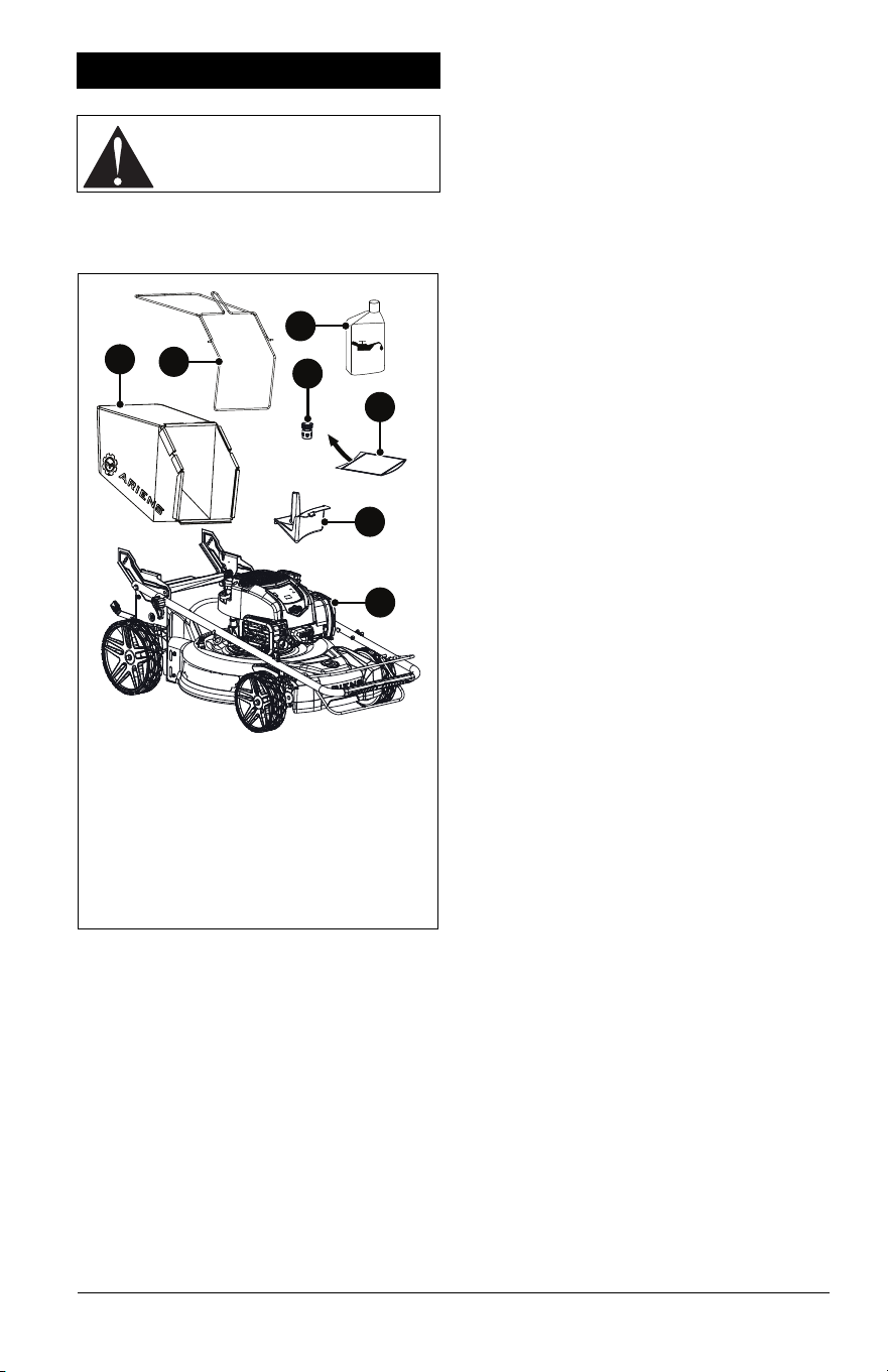
PACKAGE CONTENTS
See Figure 3.
ASSEMBLY
1. Remove contents from box.
2. Remove protective film from engine and
other components.
3. Adjust handlebar to the desired operating
position. See Adjust Handlebar Height on
page 13.
4. Add engine oil. Refer to engine manual.
5. Secure grass bag clips to wire frame.
6. Adjust height-of-cut (HOC) levers to
desired setting. See Adjust Cutting Height
on page 13.
7. Prepare mower for bagging, rear
discharge or mulching. See Prepare For
Mowing on page 11.
ASSEMBLY
CAUTION: AVOID INJURY. Read
and understand the Safety section
before proceeding.
1. Mower
2. Mulch Plug
3. Hose Coupler (Models 911607, 911608)
4. Grass Bag
5. Wire Frame
6. Literature Pack
7. Engine Oil
5
3
6
2
1
7
4
Figure 3
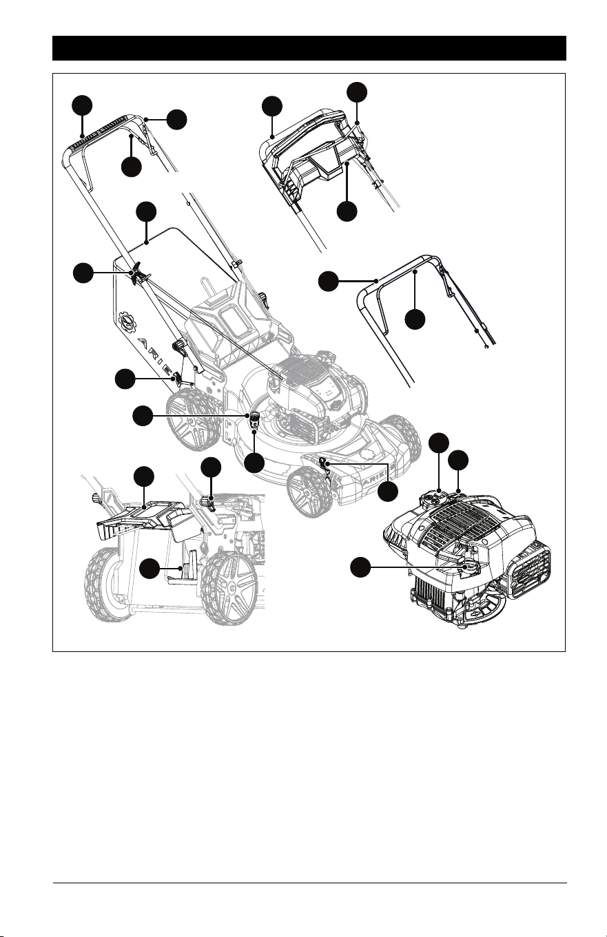
EN - 9
1. Operator Presence Control (OPC) Lever
2. Wheel Drive Control Lever (Model
911608)
3. REFLEX Drive Handle (Models 911609,
911614)
4. Handlebar
5. Height-of-Cut (HOC) Adjustment Lever
(2)
6. Grass Bag
7. Rear Door
8. Mulch Plug
9. Fuel Tank and Cap
10. Oil Fill / Dipstick
11. Air Filter
12. Recoil Starter Handle
13. Deck Washout Port (Models 911607,
911608)
14. Hose Coupler (Models 911607, 911608)
15. Handlebar Adjustment Knob (2)
CONTROLS & FEATURES
Figure 4
1
12
14
6
7
15
13
10
5
9
1
1
4
11
4
Model 911608
Models 911609,
911614
Model 911607
8
5
2
4
3
EN - 10
See Figure 4 for all controls and features
locations.
OPERATOR PRESENCE
CONTROL (OPC) LEVER
See Figure 5.
Allows for engine start, operation and blade
rotation when pulled against handlebar. Lever
MUST remain engaged to mow.
When released, blade rotation disengages
and engine stops.
IMPORTANT: Releasing the OPC lever stops
engine and blade within 3 seconds. If feature
fails, see your Ariens dealer.
REAR DOOR
Opens to collect grass clippings while
bagging. Mulch plug must be removed before
operating with bagger.
MULCH PLUG
Installs in rear panel for mulching setup. See
Mulching Grass Clippings on page 12.
GRASS BAG
Collects grass clippings for bagging setup.
See Bagging Grass Clippings on page 12.
HANDLEBAR
Height-adjustable for operator comfort. See
Adjust Handlebar Height on page 13.
CUTTING HEIGHT-ADJUSTMENT
LEVER
Adjusts cutting height from 2.5 cm – 10.2 cm
(1" – 4"). See Adjust Cutting Height on
page 13.
DECK WASHOUT PORT
Models 911607, 911608
When secured to coupler, garden hose
fastens to washout port and washes grass
clippings and debris from under deck. See
Wash Deck on page 16.
REFLEX DRIVE HANDLE
Models 911609, 911614
See Figure 6.
When pushed down, engages REFLEX drive
and propels mower forward at operator’s
pace. Release lever to stop wheel drive.
REFLEX drive system has variable speed
control. The closer its position to the bottom
of the pace match guide the faster the mower
drives forward.
CAUTION: AVOID INJURY. Read
and understand the Safety section
before proceeding.
To Start / While Mowing
Engine Stopped / Blade Rotation
Disengaged
Figure 5
Figure 6
Fast
Slow
EN - 11
WHEEL DRIVE CONTROL LEVER
Model 911608
See Figure 7.
When pulled toward handlebar, engages
wheel drive and propels mower forward.
Release lever to stop wheels.
Lever has variable speed control. The closer
its position to the handlebar, the faster the
mower drives forward.
IMPORTANT: All references to left, right, front
or rear are given from the perspective of
operator in operator’s position, facing the
direction of forward travel.
1. Know how to stop in an emergency. See
Emergency Stopping on page 14.
2. Check fuel level and add fuel if needed.
IMPORTANT: Use fresh unleaded fuel with
an octane rating of at least 87. DO NOT use
E85 blended fuels; the engine is not E15 /
E20 / E30 / E 85 compatible. The maximum
recommended ethanol content is 10%. Ariens
recommends using a quality fuel stabilizer in
all fuel. See Short-Term Storage on page 28.
3. Check engine oil level and add oil if
needed. Refer to engine manual.
4. Check air filter condition. Refer to engine
manual.
5. Check function of all controls.
EMPTY GRASS BAG
1. Lift rear door slightly and remove bag
from bag mount. See Figure 9.
2. Slowly return rear door to closed position.
3. Empty bag.
NOTICE: Clean bag and mower pan after
bagging. DO NOT allow grass to collect
inside bag or mower pan. See Clean Grass
Bag on page 16.
PREPARE FOR MOWING
Mowing setup may be adjusted between
mulching, bagging, and rear discharge.
Fast
Slow
Stop
Figure 7
BEFORE OPERATION
CAUTION: AVOID INJURY. Read
and understand the Safety section
before proceeding.
CAUTION: NEVER operate
mower with rear door open
unless bag is installed.
CAUTION: If clog or obstruction
prevents grass discharge, stop
engine, wait for moving parts to
stop and for hot parts to cool
before clearing obstruction.
EN - 12
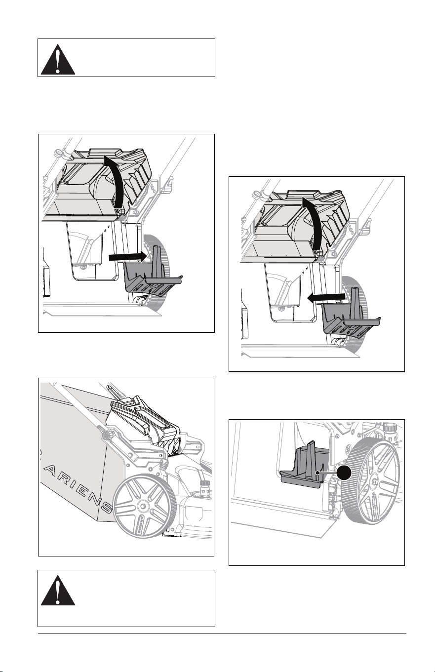
Bagging Grass Clippings
1. Stop engine and wait for moving parts to
stop and for hot parts to cool.
2. Lift rear door and remove mulch plug.
See Figure 8.
3. Hold rear door open and install grass bag
onto bag mount. Release rear door. See
Figure 9.
Rear Discharging Grass Clippings
1. Stop engine and wait for moving parts to
stop and for hot parts to cool.
2. Remove grass bag. See Empty Grass
Bag on page 11.
3. Lift rear door and remove mulch plug.
See Figure 8.
4. Slowly return rear door to closed position.
Mulching Grass Clippings
1. Stop engine and wait for all moving parts
to stop and for hot parts to cool.
2. Lift rear door and install mulch plug. See
Figure 10.
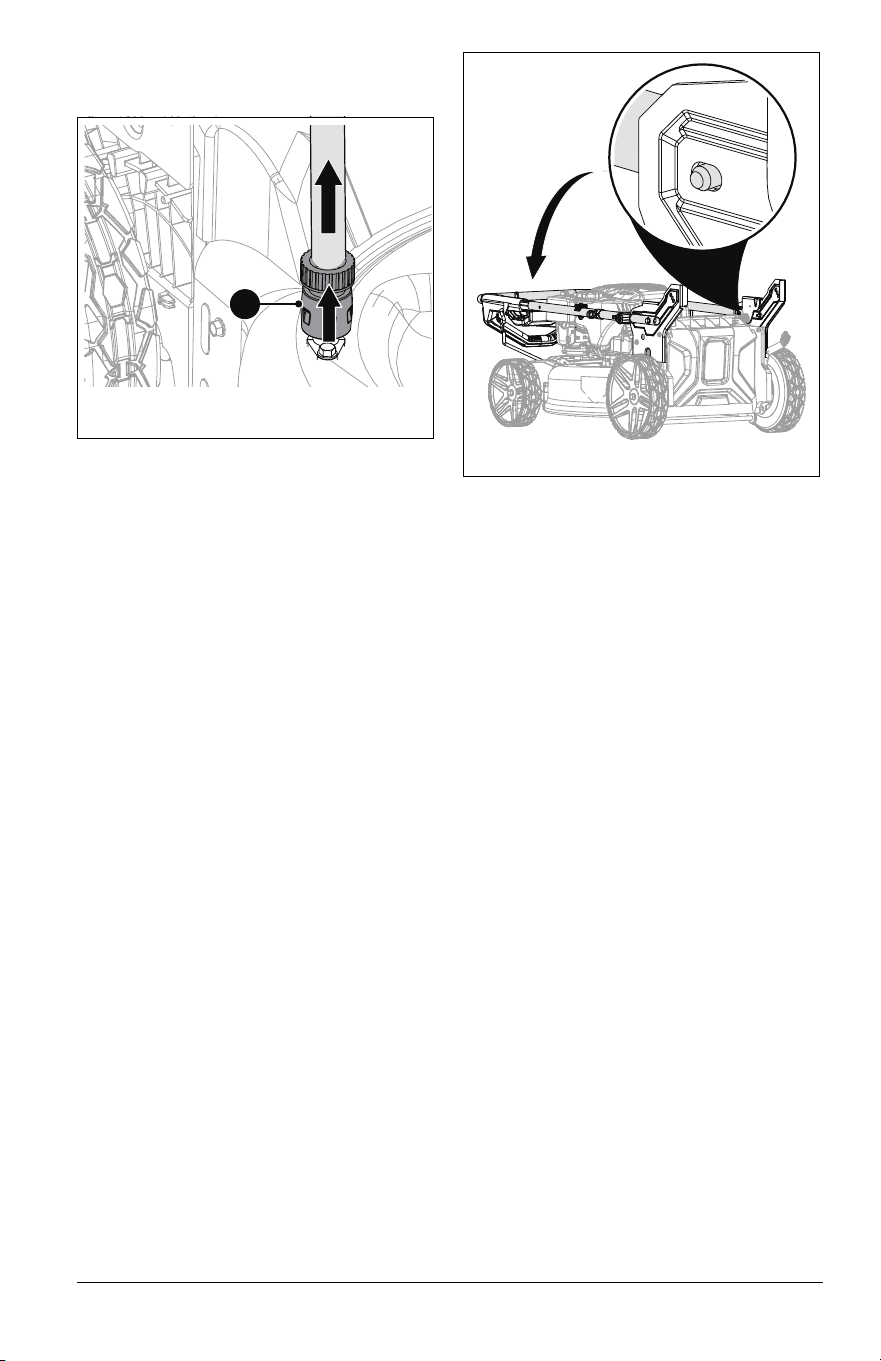
IMPORTANT: Mulch plug locks into position.
Ensure that mulch plug is secure by gently
pulling bottom of plug handle. See Figure 11.
3. Slowly return rear door to closed position.
CAUTION: Bag wears from
normal use. Check bag frequently
for wear and replace if necessary.
CAUTION: There should be no
gaps between bagger and
mounting surface. If necessary,
clear debris from bag mounting
surface.
Figure 8
Figure 9
Figure 10
Figure 11
1
1. Mulch Plug Handle
EN - 13
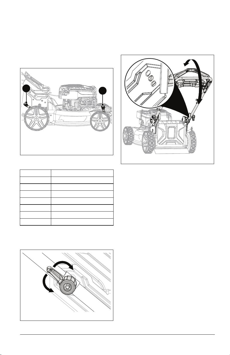
ADJUST CUTTING HEIGHT
1. Stop engine and wait for all moving parts
to stop and for hot parts to cool.
2. Pull HOC adjustment lever out of notch
and rotate lever to desired height setting.
Repeat on second adjustment lever. See
Figure 12.
IMPORTANT: Set both HOC levers to the
same setting.
CUTTING HEIGHT SETTINGS
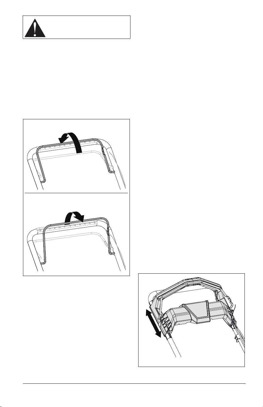
ADJUST HANDLEBAR HEIGHT
1. Rotate handlebar adjustment knobs 1/4
turn up or down. See Figure 13.
See Figure 14.
2. Position handlebar at desired height.
3. Align handlebar with desired mounting
holes.
4. Return adjustment knobs to operating
position. Ensure pins are secure in
brackets.
Notch Desired Grass Height
1 2.5 cm (1.0")
2 3.8 cm (1.5")
3 5.0 cm (2.0")
4 6.4 cm (2.5")
5 7.6 cm (3.0")
6 8.9 cm (3.5")
7 10.2 cm (4.0")
Figure 12
1. Front HOC Lever
2. Rear HOC Lever
1
2
Figure 13
Figure 14

EN - 14
1
IMPORTANT: All references to left, right, front
or rear are given from the perspective of
operator in operator’s position, facing the
direction of forward travel.
EMERGENCY STOPPING
1. Release the operator presence control
(OPC) lever.
2. Models 911609, 911614 only: Pull back
and release REFLEX drive handle.
Model 911608 only: Release wheel drive
control lever.
3. Wait for moving parts to stop before
leaving operator’s position.
START THE ENGINE
1. Pull operator presence control (OPC)
lever against handlebar and hold position.
2. Pull recoil starter handle.
a. Grasp handle and pull rope out slowly
until it pulls harder.
b. Pull handle firmly and quickly with a
rapid, continuous full-arm stroke.
c. Repeat until engine starts. If engine
does not start, see Troubleshooting
on page 27.
MOW GRASS
1. Start the engine. See Start the Engine on
page 14.
2. Model 911607: Push handlebar to move
mower forward.
Models 911609, 911614: Engage
REFLEX drive handle to move mower
forward. Release REFLEX drive handle
to stop wheel drive.
Model 911608: Engage wheel drive
control lever to move mower forward.
Release lever to stop wheel drive.
3. To make turns, stop forward motion, push
handlebar down slightly and rotate mower
left or right.
REVERSE MOWER
IMPORTANT: Mower does not have a
powered reverse.
IMPORTANT: If mower wheels lock when
pulling in reverse push mower forward to
unlock wheels. If problem persists see Adjust
Wheel Drive Control Lever / REFLEX Drive
Handle on page 21.
Model 911607:
1. Pull back on handlebar to move mower in
reverse.
Models 911609, 911614:
1. Pull back on REFLEX handle to move
mower in reverse.
Model 911608:
1. Release drive level and pull back on
handlebar to move mower in reverse.
STOP ENGINE
Model 911607
1. Release OPC lever and move unit to a
flat, level surface.
Models 911609, 911614
1. Release REFLEX drive handle.
2. Release OPC lever and move unit to a
flat, level surface.
Model 911608
1. Release wheel drive control lever.
2. Release OPC lever and move unit to a
flat, level surface.
MOWING TIPS
• Cut grass when it is dry.
• Keep mower blades sharp.
• DO NOT set cutting height too low. For tall
grass, mow twice.
• DO NOT mow too fast.
• Vary cutting pattern with each mowing.
IMPORTANT: To prevent dirt and grass from
collecting on mower pan, avoid operating
over bare ground with only patches of grass.
MULCHING TIPS
• Cut no more than 2.5 cm (1") of grass per
cutting.
OPERATION
CAUTION: AVOID INJURY. Read
and understand the Safety section
before proceeding.
EN - 15
Your Ariens dealer can provide service and
adjustments to keep your unit operating at
peak efficiency. Contact an authorized engine
manufacturer’s service center for engine
service.
MAINTENANCE SCHEDULE
SERVICE PARTS
See your Ariens dealer to purchase service
parts for your unit.
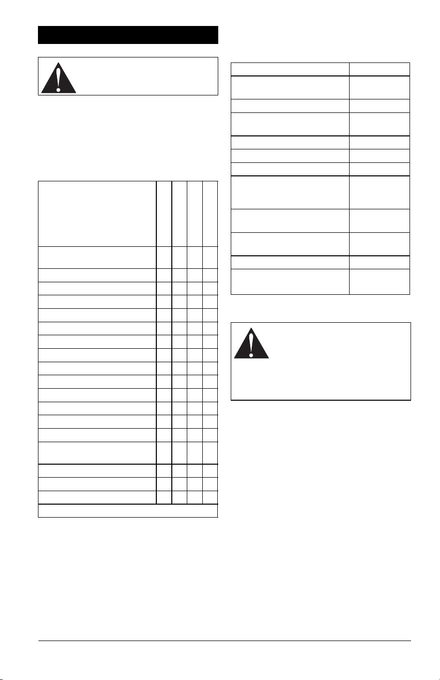
SERVICE POSITION
1. Place unit on a flat, level surface.
2. Stop engine and wait for all moving parts
to stop and for hot parts to cool.
3. Drain fuel from fuel tank and fuel system.
Refer to engine manual for instructions.
4. Disconnect spark plug wire.
5. Adjust handlebar to full vertical position.
See Adjust Handlebar Height on page 13.
6. Rotate unit onto its right side. Ensure the
unit is secure and will not tip. See
Figure 15.
MAINTENANCE
CAUTION: AVOID INJURY. Read
and understand the Safety section
before proceeding.
Service Performed
Each Use
Every 5 hrs.
Every 25 hrs.
Every 100 hrs.
Check Operator Presence
Control
•
Check Wheel Drive Control •
Check Grass Bag •
Clean Unit •
Check Engine Oil * •
Check Cooling Fins * •
Check Mower Blade •
Check Drive Belt •
Check Fasteners •
Wash Deck •
Clean Grass Bag •
Check Air Filter * •
Change Engine Oil *
General Lubrication •
Check OPC Lever Cable
Adjustment
•
Check Spark Plug *
Clean Engine Cooling Fins * •
Check Muffler •
* Refer to engine manual for instructions.
Description Part No.
Air Cleaner (Models 911607,
911609, 911608)
21575020
Air Filter 21575023
Air Filter Foam Pre-Cleaner
(Model 911614)
21575024
Replacement Blade Kit 71107500
Laser Edge Blade Kit 71107600
Dual Blade Kit 71107700
Dual Blade Upgrade Kit
(Models 911607, 911609,
911608)
71107800
Transmission Belt (Model
911608)
07200923
Transmission Belt (Models
911609, 911614)
07200924
Grass Collector Bag 30122000
Fuel Stabilizer – 118 mL
(4 oz)
04730400
CAUTION: AVOID INJURY.
Before placing unit in service
position, drain fuel from tank and
fuel system. (Refer to engine
manual for instructions).
Make sure unit is secure and will
not tip.
EN - 16
CHECK ENGINE OIL
NOTICE: Engine oil level MUST be
maintained at correct level or engine damage
may occur. Refer to engine manual.
CHANGE ENGINE OIL
Refer to engine manual.
CLEAN ENGINE COOLING FINS
Cooling fins circulate air around cylinder head
and engine block. Engine may overheat if fins
are clogged or damaged. Refer to engine
manual.
CHECK AIR FILTER
Check air filter and replace if clogged or
damaged. Refer to engine manual.
CLEAN GRASS BAG
Check grass bag frequently for wear.
Remove grass bag, empty grass clippings,
wash with garden hose and allow it to dry.
Replace worn or damaged bag with Ariens
original equipment only.
Clean grass clippings and other debris from
mower pan. See Figure 16.
WASH DECK
NOTICE: DO NOT clean topside of deck with
water. To avoid engine damage, clean debris
from the topside of the deck using
compressed air or a dry cloth.
Models 911607, 911608
See Figure 17.
Occasional deck cleaning with the washout
port prevents debris buildup and maintains
cutting efficiency.
IMPORTANT: Use of the washout port may
deposit a dark-green residue on surface
where deck was cleaned.
1. Move unit to a flat, level surface.
2. Stop engine and wait for moving parts to
stop and for hot parts to cool.
NOTICE: DO NOT use washout port when
mower is warm from operation.
3. Secure coupler to garden hose.
4. Firmly push coupler onto washout port
until coupler clicks.
5. Gently tug on the hose to verify coupler is
secure.
IMPORTANT: If water leaks from coupler,
coupler is not secure.
6. Open water-supply valve.
7. Start engine and engage mower blade.
Keep blade engaged until water color
under deck changes from green to clear.
See Start the Engine on page 14.
8. Stop engine and wait for all moving parts
to stop and for hot parts to cool. See Stop
Engine on page 14.
Figure 15
Figure 16
Figure 17
1. Hose Coupler
2. Washout Port
1
2
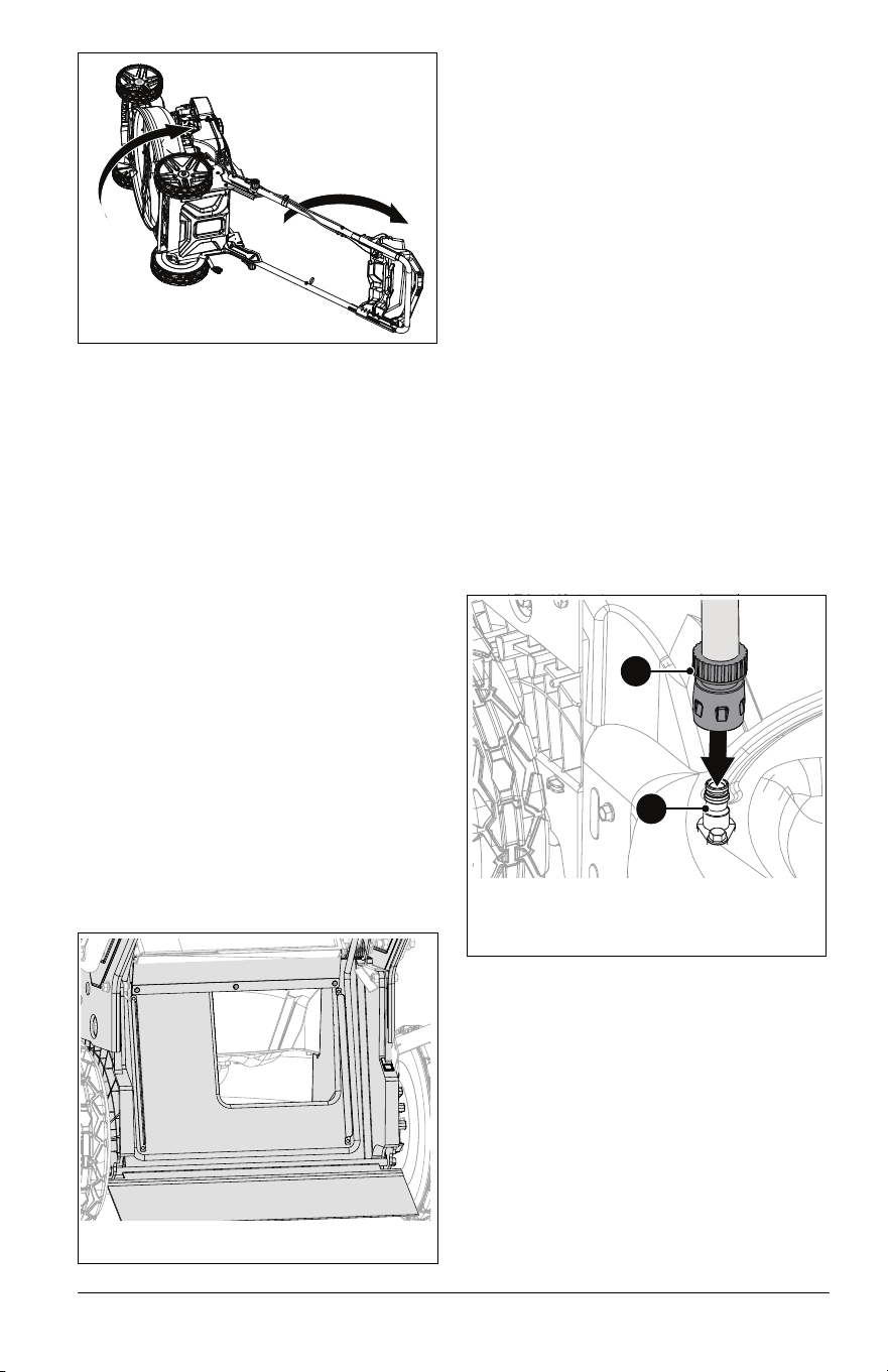
EN - 17
9. Pull lock collar away from washout port
and remove hose from port. See
Figure 18.
10. Remove coupler from hose end.
11. Start engine and engage blade for
approximately 2 – 3 minutes to remove
excess water from unit.
12. Stop engine and allow deck to dry before
storing.
Models 911609, 911614
1. Move unit to a flat, level surface.
2. Stop engine and wait for moving parts to
stop and for hot parts to cool.
3. Clean underside of deck with mild soap
and low-pressure water.
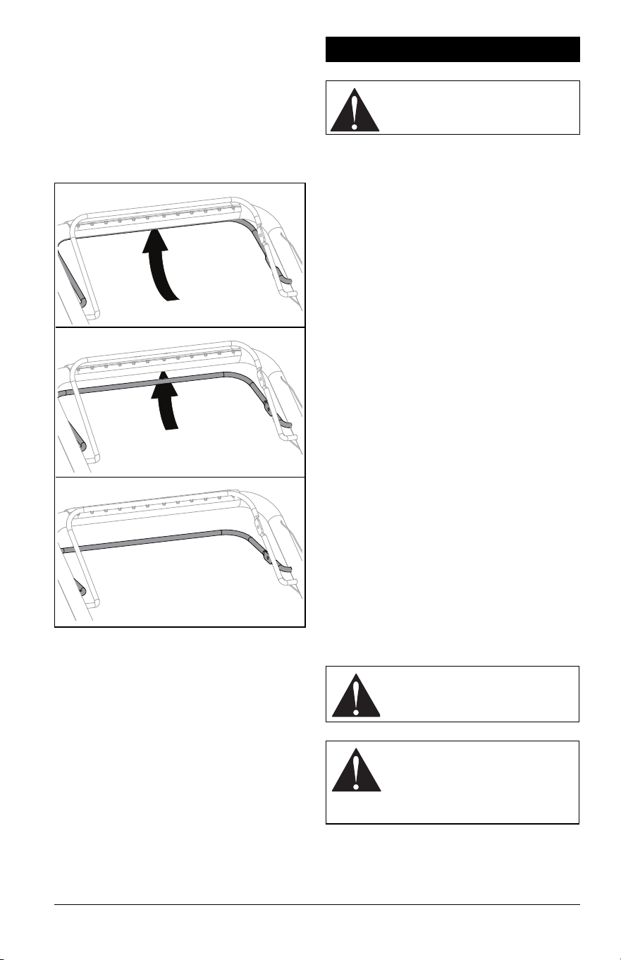
STORAGE POSITION
1. Move unit to a flat, level surface.
2. Stop engine and wait for moving parts to
stop and for hot parts to cool.
3. Rotate handlebar adjustment knobs 1/4
turn up or down.
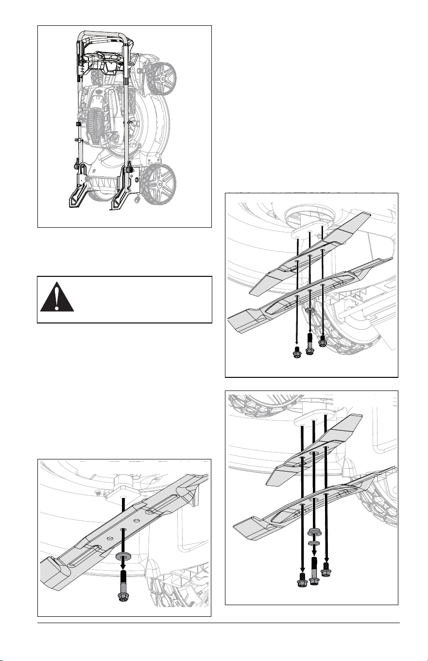
4. Fold handlebar forward and align
adjustment knobs with front mounting
holes. Ensure pins are secure in
brackets. See Figure 19.
5. Models 911609, 911614 Only: Place unit
in vertical storage position. See Vertical
Storage Position on page 17.
NOTICE: Models 911609, 911614 are
equipped with engines that make it possible
to store unit in the upright position. To prevent
fluid leaks, DO NOT store Models 911607,
911608 in vertical storage position.
6. Return adjustment knobs to original
position.
VERTICAL STORAGE POSITION
Models 911609, 911614
IMPORTANT: Adjust HOC to setting 3 or 4
when storing unit in vertical storage position.
See Adjust Cutting Height on page 13.
See Figure 20.
1. Place unit in storage position. See
Storage Position on page 17.
2. Models 911609, 911614 Only: Tip unit
onto rear brackets.
1. Lock Collar
1
Figure 18
Figure 19
EN - 18
CHECK MOWER BLADE(S)
Check blade(s) for wear. Replace or sharpen
as necessary.
Remove Blade
Models 911607, 911609, 911608
1. Stop engine and wait for all moving parts
to stop and for hot parts to cool.
2. Disconnect spark plug wire.
3. Place unit in service position. See
Service Position on page 15.
4. Block blade to prevent rotation.
5. Remove hardware retaining blade and
remove blade. Retain hardware. See
Figure 21.
Remove Blades
NOTICE: Some dual blade machines feature
an additional spacer. Configure per machine
specifications.
Model 911614
1. Stop engine and wait for all moving parts
to stop and for hot parts to cool.
2. Disconnect spark plug wire.
3. Place unit in service position. See
Service Position on page 15.
4. Block blades to prevent rotation.
5. Remove and retain hardware securing
blades to blade adapter. Remove blades,
washer, and if included remove spacer.
See Figure 22 and Figure 23.
CAUTION: AVOID INJURY. Use
sturdy gloves or padding to protect
hands when handling mower
blade(s).
Figure 20
Figure 21
Models 911607, 911609, 911608
Figure 22
Model 911614
Figure 23
Model 911614
EN - 19
Sharpen Blade
NOTICE: DO NOT sharpen laser edge
blades.
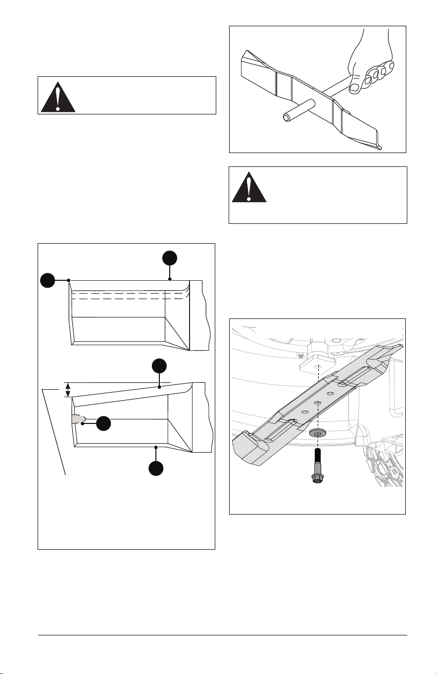
See Figure 24.
1. Remove mower blade. Discard blade if:
• More than 1.3 cm (1/2") of metal is
gone.
• Air lifts are eroded.
• Blade is bent or broken.
2. File or grind an equal amount of metal
from each cutting edge of blade until
sharp.
IMPORTANT: DO NOT change angle of
cutting edge or round the corner of blade.
3. Slide an unthreaded bolt through blade
center to check balance. Hold the bolt
level. If blade does not remain horizontal,
sharpen the heavy end until blade is
balanced. See Figure 25.
4. Reinstall mower blade. See Install Blade
on page 19.
Install Blade
Models 911607, 911609, 911608
1. Position blade against blade adapter and
secure with original hardware. See
Figure 26.
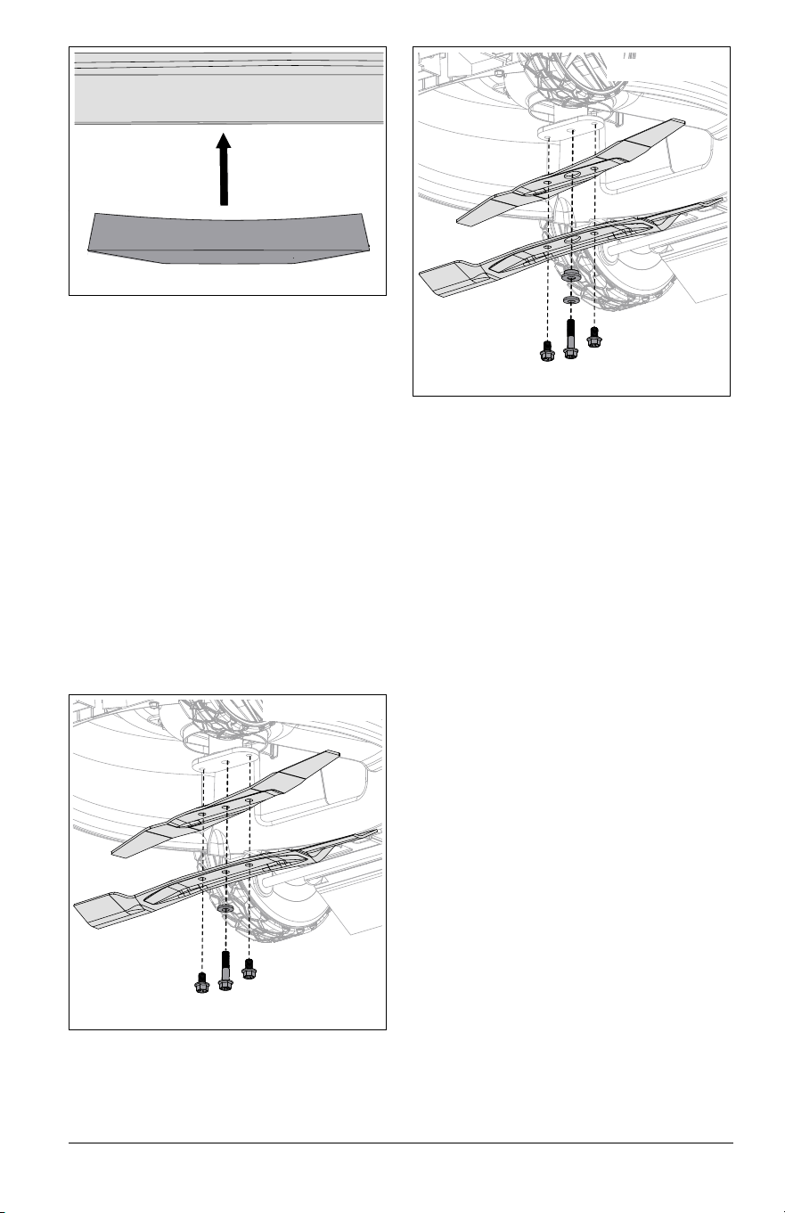
NOTICE: Washer must be positioned
concave side towards blade and blade MUST
be installed with cutting edges positioned
upward. See Figure 27.
CAUTION: AVOID INJURY. DO
NOT sharpen blade while
attached to unit.
Sharpen to this pattern.
DO NOT sharpen to this
pattern.
DISCARD if more than 1.3 cm (1/2").
1
2
2
4
3
1. Square Corner
2. Cutting Edge
3. Air Lift
4. Air Lift Erosion
Figure 24
CAUTION: An unbalanced blade
causes excessive vibration and
eventual damage to unit. Balance
blade before reinstalling.
NEVER weld or straighten blade.
Figure 25
Figure 26
Models 911607, 911609, 911608
EN - 20
2. Torque hardware to 61 N*m (45 lb-ft).
3. Return unit to operating position and
reconnect spark plug wire.
Install Blades
Model 911614
NOTICE: Some dual blade machines feature
an additional spacer. Configure per machine
specifications.
1. Position blades against blade adapter
and secure with original hardware. See
Figure 28.
OR
Position blades, washer, and spacer
against blade adapter. See Figure 29.
NOTICE: Washer must be positioned
concave side towards blade and blades
MUST be installed with cutting edges
positioned upward. See Figure 27.
2. Torque center bolt to 61 N*m (45 lb-ft),
torque outer two bolts to 40.7 N•m (30 lb-
ft).
3. Return unit to operating position and
reconnect spark plug wire.
CHECK DRIVE BELT
Models 911609, 911614, 911608
Check drive belt and replace if worn or
damaged. See Replace Drive Belt on
page 23.
CHECK FASTENERS
Check for loose or missing hardware. Give
special attention to blade hardware and all
guards, shields and safety devices.
LUBRICATE UNIT
1. Apply oil to all pivot points and pin
connections.
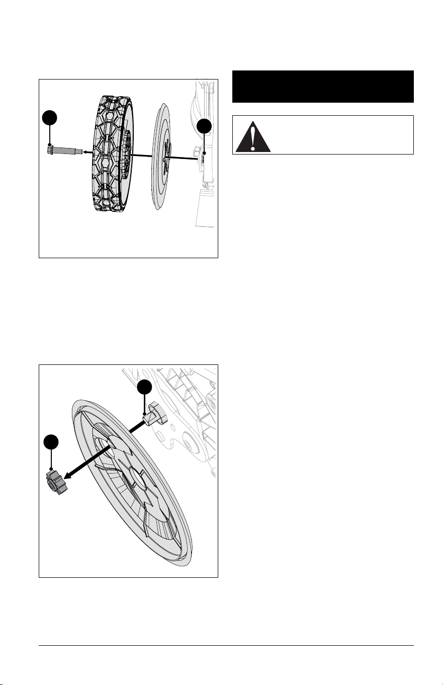
Lubricate Ground Drive System
Models 911609, 911614, 911608
See Figure 30.
IMPORTANT: Lubricate both sides of ground
drive system.
1. Place a support, such as a wood block,
under deck rear.
2. Models 911609, 911614: Place rear of
unit in highest height of cut position.
Remove locking nuts from behind wheel
plates. Remove shoulder bolts retaining
rear wheels and remove wheels.
Figure 27
Figure 28
Model 911614
Figure 29
Model 911614
EN - 21
3. Model 911608: Place front of unit in
highest height of cut position. Remove
locking nuts from behind wheel plates.
Remove shoulder bolts retaining front
wheels and remove wheels.
See Figure 31.
4. Remove pinion gears.
5. Clean dirt and debris from transmission
shaft ends and pinion gears. Apply anti-
seize compound to shaft end.
NOTICE: DO NOT apply grease to gear
teeth. Clean grease and debris from gear
teeth before reassembly.
3. Reinstall pinion gears.
4. Apply recommended amount of Red
Loctite® 263 (or equivalent) locking
compound to shoulder bolts.
5. Reinstall wheels and secure with
previously removed hardware.
6. Torque shoulder bolts and locking nuts to
16.3 N•m (144 in-lbs).
IMPORTANT: All references to left, right, front
or rear are given from the perspective of
operator in operator’s position, facing the
direction of forward travel.
ADJUST WHEEL DRIVE
CONTROL LEVER / REFLEX
DRIVE HANDLE
1. Model 911608 only: Mower forward
speed should increase as wheel drive
control lever is pulled closer to handle. If
unit does not accelerate smoothly, slips
under load or creeps forward when lever
is released, wheel drive control cable may
require adjustment.
2. Models 911609, 911614 only: Mower
forward speed should increase as
REFLEX drive handle is pushed down to
match operator’s pace. If unit does not
accelerate smoothly, slips under load or
creeps forward when handle is released,
wheel drive control cable may require
adjustment.
IMPORTANT: DO NOT over-adjust cable and
disable the return-to-neutral function.
Forward drive MUST stop immediately when
wheel drive control lever is released.
3. Stop engine and wait for moving parts to
stop and for hot parts to cool.
4. Clean dirt and debris from the drive
components.
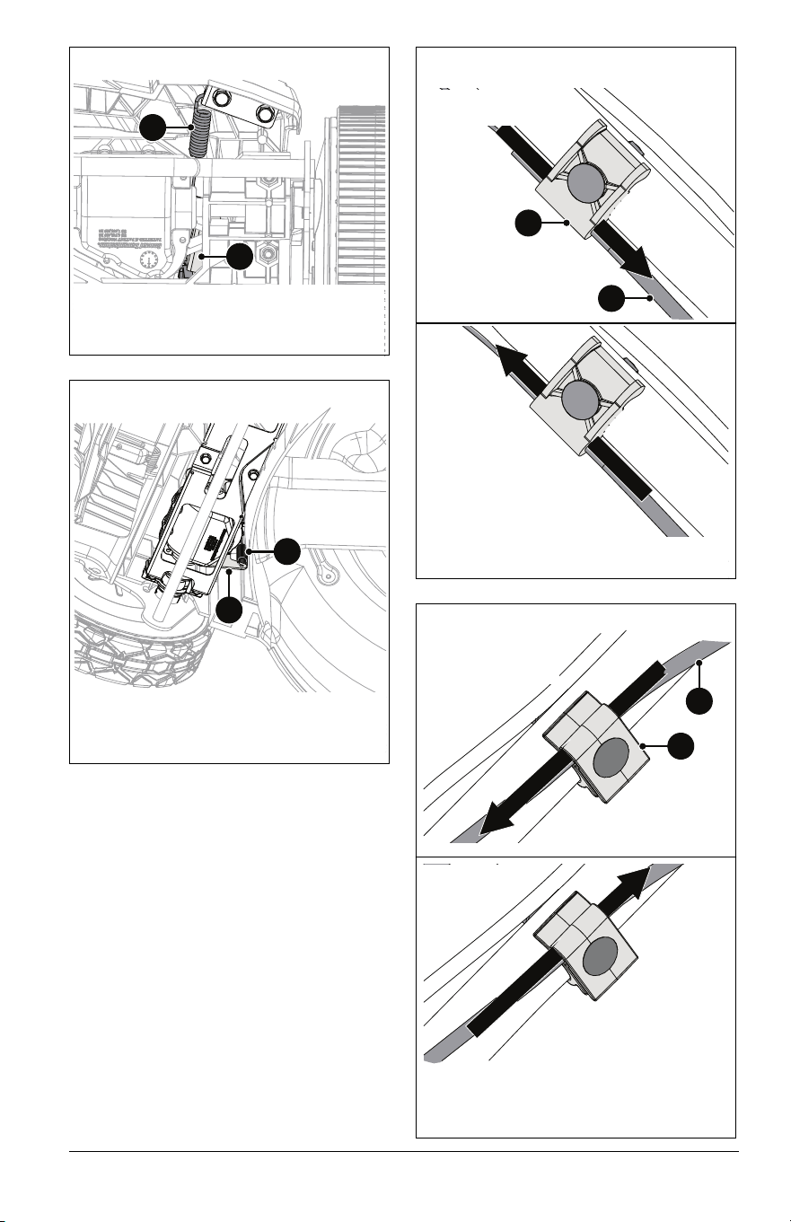
IMPORTANT: Ensure extension spring is
connected to transmission bracket. See
Figures 32 and 33.
Figure 30
2
1
1. Shoulder Bolt
2. Locking Nut
1
2
1. Transmission Shaft
2. Pinion gear
Figure 31
SERVICE &
ADJUSTMENTS
CAUTION: AVOID INJURY. Read
and understand the Safety section
before proceeding.
EN - 22
See Figures 34 and 35.
5. Loosen hardware on cable guide clamp.
6. Adjust wheel drive cable tension:
• To increase wheel drive control lever /
REFLEX drive handle response, lower
cable and tighten clamp hardware.
• To decrease wheel drive control lever /
REFLEX drive handle sensitivity, raise
cable and tighten clamp hardware.
7. Torque to 4.0 N*m (35 in-lbs).
1. Extension Spring
2. Transmission Bracket
Figure 32
1
2
Model 911608
1. Extension Spring
2. Transmission Bracket
Figure 33
Models 911609, 911614
1
2
Increase Cable
Tension / Speed
Decrease Cable
Tension / Speed
1. Adjustment Cable
2. Cable Guide Clamp
Figure 34
2
1
Models 911609, 911614
Figure 35
Decrease Cable
Tension / Speed
1. Adjustment Cable
2. Cable Guide Clamp
2
1
Increase Cable
Tension / Speed
Model 911608
EN - 23
7. Check the adjustment:
a. Start the engine. See Start the Engine
on page 14.
b. Model 911608 only: Slowly pull wheel
drive control lever against handlebar.
Unit should move forward smoothly
and increase in speed as lever is
pulled closer to handlebar.
Models 911609, 911614 only: Slowly
push down on REFLEX drive
handle.The unit should move forward
smoothly and increase in speed as
handle is pushed down to match
operator’s pace.
c. Release wheel drive control lever or
handle. Unit should stop immediately
and not creep forward.
d. Pull back on handlebar and ensure
wheels are not locked in place. If
wheels are locked stop the engine
and slightly decrease cable tension.
Recheck adjustment.
ADJUST OPERATOR PRESENCE
CONTROL (OPC) LEVER
The OPC lever is non-adjustable. If engine
and / or blade does not stop within 3 seconds
of releasing the OPC lever, see your Ariens
dealer.
REPLACE DRIVE BELT
Models 911609, 911614, 911608
Remove Drive Belt
All Models:
1. Disconnect spark plug wire.
2. Remove hardware securing blade(s) to
blade adapter and remove blade(s). See
Remove Blade on page 18 or Remove
Blades on page 18.
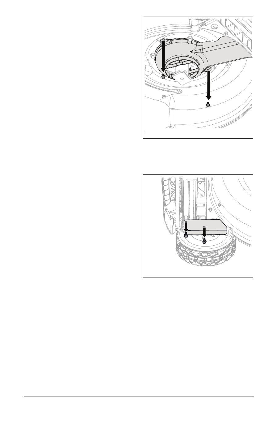
3. Remove two hex screws retaining spindle
pulley cover and remove cover. See
Figure 36.
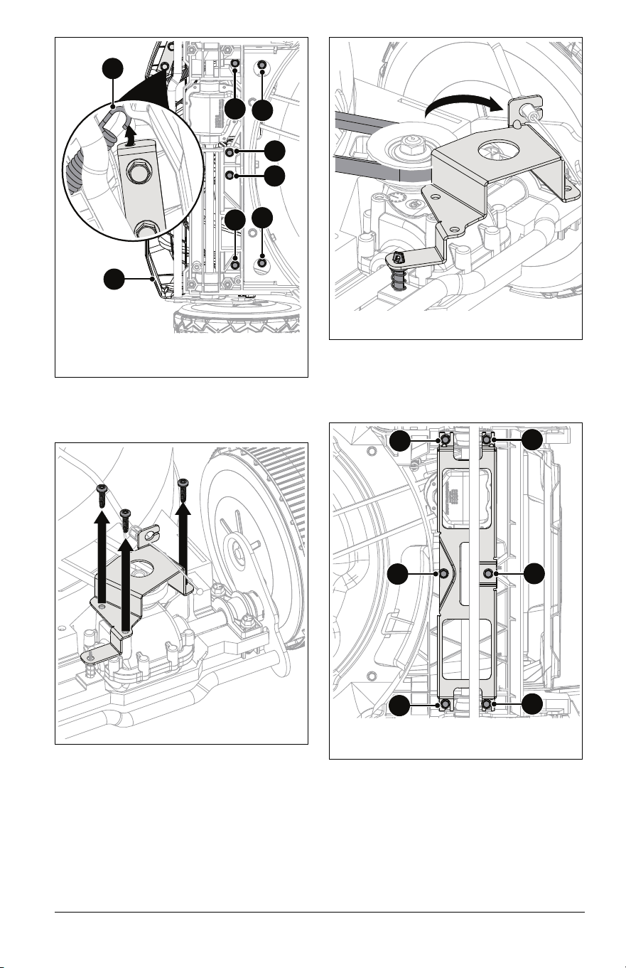
Model 911608 only:
1. Remove and retain flange bracket
hardware and remove bracket. See
Figure 37.
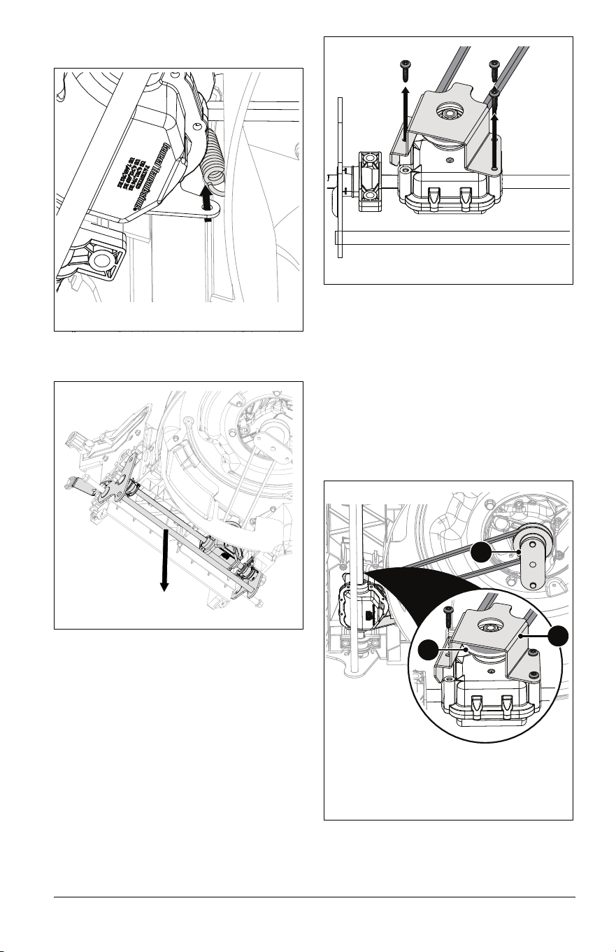
See Figure 38.
2. Disconnect extension spring from cable
anchor.
3. Remove and retain six hex screws
securing front cover and remove cover.
Figure 36
Figure 37
EN - 24
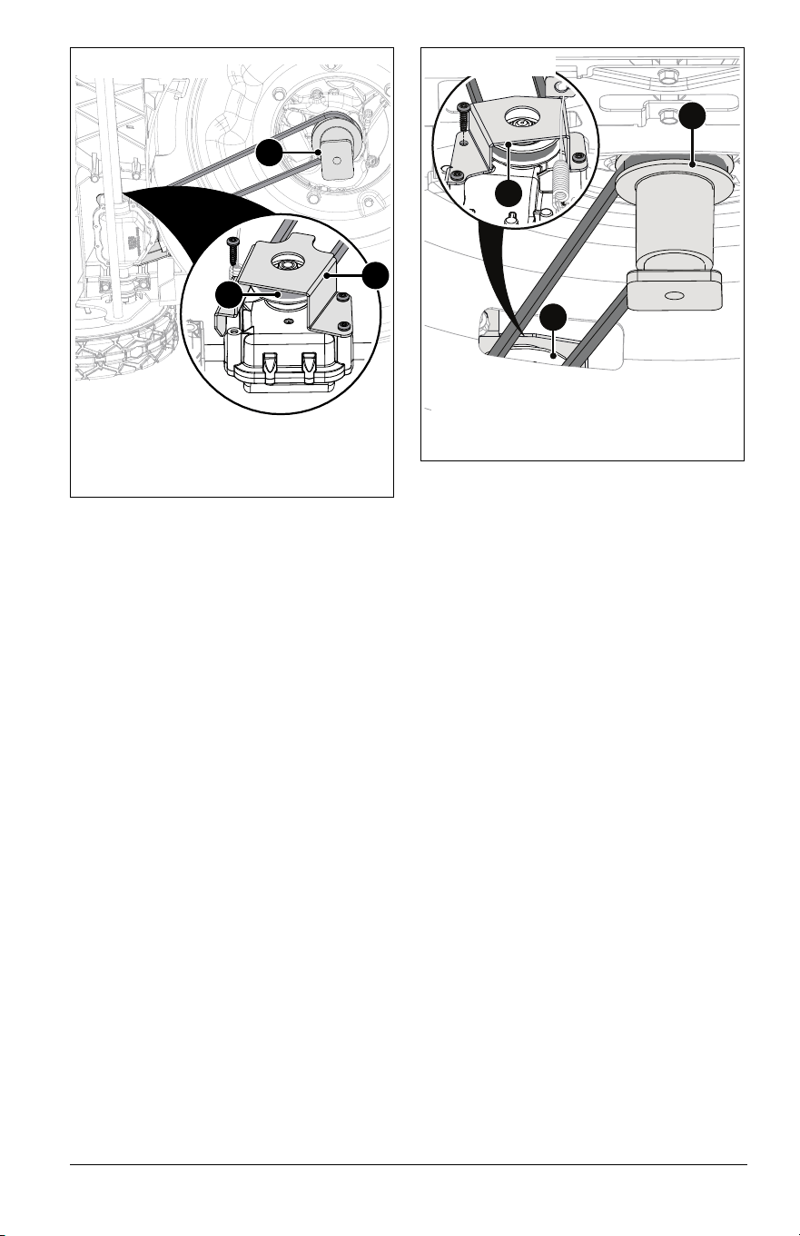
4. Remove and retain three Torx head
screws from transmission bracket. See
Figure 39.
See Figure 40.
5. Rotate transmission bracket around
return spring holder to access belt.
6. Remove drive belt.
Models 911609, 911614 only:
1. Remove and retain six hex screws from
support bracket and remove bracket. See
Figure 41.
See Figures 30 and 31.
2. Place a support, such as a wood block,
under deck rear.
3. Remove shoulder bolts retaining rear
wheels and remove wheels.
4. Remove pinion gears and dust cover.
1. Hex Screws
2. Cover
3. Extension Spring
Figure 38
1
1
1
1
1
1
2
3
Figure 39
Figure 40
Figure 41
1. Hex Screws
1
1
1
1
1
1
EN - 25
5. Disconnect extension spring from
transmission bracket. See Figure 42.
6. Remove transmission assembly. See
Figure 43.
7. Remove and retain three Torx head
screws from transmission bracket and
remove bracket. See Figure 44.
8. Remove drive belt.
Install Drive Belt
Models 911609, 911614 only:
See Figures 45 and 46.
1. Install drive belt around transmission
pulley.
2. Reinstall transmission bracket using
original hardware. Torque to 5.1 N•m (45
in-lbs).
3. Position transmission assembly in
grooves of baffle.
4. Install belt around spindle pulley.
Figure 42
Figure 43
Figure 44
1. Transmission Pulley
2. Transmission Bracket
3. Spindle Pulley
Figure 45
1
2
3
Model 911614
EN - 26
5. Reconnect extension spring.to
transmission bracket.
6. Reinstall support bracket using original
hardware. Torque outer hardware to
2.8 N•m (25 in-lbs).
IMPORTANT: Ensure bracket is in correct
orientation as shown in Figure 41.
7. Reinstall pinion gear and dust cover.
8. Reinstall rear wheels using original
hardware. Torque bolts to 16.3 N•m (144
in-lbs).
9. Reinstall spindle pulley cover using
original hardware. Torque to 2.8 N•m (25
in-lbs).
10. Reinstall blade(s) using original
hardware. See Install Blade on page 19
or Install Blades on page 20.
11. Reconnect spark plug wire.
Model 911608 only:
See Figure 47.
1. Install drive belt around transmission
pulley.
2. Reinstall transmission bracket using
original hardware. Torque to 5.1 N•m (45
in-lbs).
NOTICE: Ensure the return spring is properly
connected to the transmission bracket.
3. Install belt around spindle pulley.
4. Reinstall front cover using original
hardware.
5. Reconnect extension spring to
transmission bracket.
6. Reinstall spindle pulley cover using
original hardware. Torque to 2.8 N•m (25
in-lbs).
7. Reinstall flange bracket using original
hardware.
8. Reinstall blade using original hardware.
See Install Blade on page 19.
9. Reconnect spark plug wire.
1. Transmission Pulley
2. Transmission Bracket
3. Spindle Pulley
Figure 46
1
2
3
Model 911609
1. Transmission Pulley
2. Transmission Bracket
3. Spindle Pulley
Figure 47
2
1
3
Model 911608

EN - 27
TROUBLESHOOTING
Problem Probable Cause Correction
Engine will not start.
Fuel tank empty or low. Check fuel level. Fill tank if necessary.
Spark plug wire loose or off. Check connection.
Operator presence control
(OPC) lever disconnected,
broken or out of adjustment.
See your Ariens dealer.
Engine is difficult to
restart.
Mower clogged with grass
clippings.
Clear debris from under mower. See
Wash Deck on page 16.
Cutting quality is
poor.
Blade is worn / dull. Check blade and sharpen if necessary.
See Check Mower Blade(s) on page 18.
Cutting height is too low. Raise cutting height. See Adjust Cutting
Height on page 13.
Grass is wet. Wait for grass to dry.
Mowing speed is too fast. Mow slower.
Grass does not
disperse evenly.
Cutting height is too low. Raise cutting height. See Adjust Cutting
Height on page 13.
Grass is wet. Wait for grass to dry.
Mowing speed is too fast. Mow slower.
Mower does not bag
clippings.
Grass bag is overfilled. Empty grass bag.
Mulch plug is installed. Remove mulch plug. See Bagging Grass
Clippings on page 12.
Wheel drive does
not engage (Models
911609, 911614,
911608).
Wheel drive control lever or
handle not engaged.
Engage wheel drive control lever or
handle.
Drive belt out of position. Check drive belt and adjust if necessary.
See Adjust Wheel Drive Control Lever /
REFLEX Drive Handle on page 21.
Drive belt worn or
damaged.
Replace belt. See Replace Drive Belt on
page 23.
Wheel drive control cable
disconnected, broken or out
of adjustment.
Check cable and adjust or replace as
necessary. See Adjust Wheel Drive
Control Lever / REFLEX Drive Handle on
page 21.
Wheel bearings worn or
damaged.
See your Ariens dealer.
Debris caught in drive
gears.
Clean dirt and debris from transmission
shaft ends and pinion gears. See
Lubricate Ground Drive System on
page 20.
Drive belt slips or speed is
too slow.
See Adjust Wheel Drive Control Lever /
REFLEX Drive Handle on page 21 or
replace drive belt. See Replace Drive
Belt on page 23.
Wheels do not
release when
reversing mower.
(Models 911609,
911614, 911608).
Wheel drive control cable
disconnected, broken or out
of adjustment.
Check cable and adjust or replace as
necessary. See Adjust Wheel Drive
Control Lever / REFLEX Drive Handle on
page 21.

EN - 28
SHORT-TERM STORAGE
1. Stop engine and wait for moving parts to
stop and for hot parts to cool.
2. Empty grass bag.
3. Tighten all hardware to correct
specifications.
4. Inspect unit for visible signs of wear or
damage. Repair as needed.
5. Apply a light layer of oil or anti-rust
compound on bare metal areas.
6. Prepare fuel system for storage.
NOTICE: Ariens recommends using a quality
fuel stabilizer in all fuel. Gasoline left in the
fuel system without a stabilizer, even for short
periods of time, deteriorates and leaves
gummy deposits in the system that may
damage the carburetor and fuel hoses, filter
and tank. For the best effectiveness, add
stabilizer to all fuel containers whenever
purchasing fuel. Add the stabilizer to the
container before adding fuel.
a. Add Ariens fuel stabilizer (see Service
Parts on page 15) or equivalent
according to manufacturer’s
instructions to the fuel tank and any
fuel containers with remaining fuel.
b. Operate engine outdoors for at least 5
minutes to allow stabilizer to reach the
carburetor.
7. Store unit in a cool, dry, protected area.
DO NOT store unit outdoors.
8. Models 911609, 911614: Place unit in the
vertical storage position for compact
storage. See Vertical Storage Position on
page 17.
LONG-TERM STORAGE
1. Perform all short-term storage items.
2. Wash grass bag and allow it to dry.
3. Wash unit with mild soap and low-
pressure water.
IMPORTANT: NEVER wash unit with high-
pressure water.
4. Lubricate as directed in Maintenance on
page 15.
5. Clean grass clippings and debris from
under deck. See Wash Deck on page 16.
6. Touch up all scratched painted surfaces.
7. Store unit in a cool, dry, protected area.
DO NOT store unit outdoors. Rotate
handlebar forward for compact storage.
See Adjust Handlebar Height on page 13.
START-OF-SEASON FUEL
PREPARATION
Before opening the fuel valve for the first time
after long-term storage, add fresh, stabilizer-
treated fuel to the fuel tank and any fuel
containers with remaining fuel.
See your Ariens dealer for a complete list of
compatible accessories and attachments for
your unit.
STORAGE
CAUTION: AVOID INJURY. Read
and understand the Safety section
before proceeding.
ACCESSORIES
Description Part No.
Standard Blade Kit 71107500
Laser Edge Blade Kit 71107600
Dual Blade Laser Edge Kit 71107700
Dual Blade Laser Edge
Upgrade Kit
71107800
Engine Maintenance Kit (Model
911607)
70732800
Engine Maintenance Kit
(Models 911609, 911608)
70732900
Engine Maintenance Kit (Model
911614)
70733000

EN - 29
SPECIFICATIONS
Model Number 911607 911609
Description Push
Self-Propelled with
REFLEX™ Drive
Engine
Briggs & Stratton
®
EX 625
Briggs & Stratton
EXi 725
Displacement – cm
3
(in
3
)
150 (9.2) 163 (9.9)
Maximum RPM – No load. 3200 ± 100
Crank Case Capacity – liter (oz) 0.4 (15)
Air Cleaner Paper Element
Oil Filter N/A
Engine Oil Refer to engine manual.
Cylinder Bore Aluminum
Starter Recoil
Fuel
Type Refer to engine manual.
Fuel Tank Capacity – L (gal.) 1.0 (0.27)
Drive
Variable Speeds – kph (mph) N/A 0 - 6.4 (0 - 4.0)
Dimensions
Length – cm (in) 162.6 (64) 157.5 (62)
Height – cm (in) 101.6 (40) 104.1 (41)
Width – cm (in) 55.9 (22)
Actual Weight – kg (lb) 29.5 (65) 30 (75)
Mower Deck
Material 14 Gauge – Stamped Steel
Cutting Width – cm (in) 53 (21.0)
Cutting Height – cm (in) 2.5 – 10.2 (1.0 – 4.0)
Front Wheel Diameter – cm (in) 20.3 (8.0)
Rear Wheel Diameter – cm (in) 25.4 (10.0)
Max Rotation Speed of Cutting Edge – RPM 3,300
Deck Lift Mechanical Levers

EN - 30
SPECIFICATIONS
Model Number 911614 911608
Description
Dual Blade with
REFLEX™ Drive
Self-Propelled
Engine
Briggs & Stratton
EXi 875
Briggs & Stratton
EXi 725
Displacement – cm
3
(in
3
)
190 (11.6) 163 (9.9)
Maximum RPM – No load. 3200 ± 100
Crank Case Capacity – liter (oz) 0.5 (18) 0.4 (15)
Air Cleaner Paper Element
Oil Filter N/A
Engine Oil Refer to engine manual.
Cylinder Bore Cast Iron
Starter Recoil
Fuel
Type Refer to engine manual.
Fuel Tank Capacity – L (gal.) 1.0 (0.27)
Drive
Variable Speeds – kph (mph) 0 - 6.4 (0 - 4.0) 0 - 6.0 (0-3.7)
Dimensions
Length – cm (in) 157.5 (62) 162.6 (64)
Height – cm (in) 104.1 (41) 101.6 (40)
Width – cm (in) 55.9 (22)
Actual Weight – kg (lb) 36.3 (80) 33.1 (73)
Mower Deck
Material 14 Gauge – Stamped Steel
Cutting Width – cm (in) 53.3 (21.0)
Cutting Height – cm (in) 2.5 – 10.2 (1.0 – 4.0)
Front Wheel Diameter – cm (in) 20.3 (8.0)
Rear Wheel Diameter – cm (in) 25.4 (10.0)
Max Rotation Speed of Cutting Edge –
RPM
3,300
Deck Lift Mechanical Levers

8/23 • 05299800K
EN - 31
AriensCo warrants to the original purchaser that Ariens brand products purchased on or after 09/01/2022
will be free from defects in material and workmanship for the time period noted in the chart below. Equipment
put to personal use around a single household or residence is considered “Residential Use.” Equipment put
to any business use (agricultural, commercial, or industrial) or used at multiple locations is considered
“Commercial Use.” If any product is rented or leased, then the duration of these warranties shall be 90 days
after the date of purchase.
An authorized Ariens dealer will repair any defect in material or workmanship, and repair or replace any
defective part, subject to the conditions, limitations and exclusions set forth herein. Such repair or
replacement will be free of charge (labor and parts) to the original purchaser; except as noted below. Pick-up
and delivery are at the owner’s expense.
The warranty code is found on the model and serial number identification label on the unit.
* Whichever comes first.
Special Extensions
The chart below details special extensions to warranty terms. Warranty terms are total time periods
covered. If any product is rented or leased, there are no extensions to the 90-day warranty.
Outdoor Power
Equipment
Limited Warranty
Warranty
Code
Product Group Warranty Period
AA Serialized Attachments 1 Year.
CH, CQ ZENITH Mowers 4 Years or 750 Hours.*
HD RAZOR Walk-Behind Mowers 3 Years Residential Use. 90 Days Commercial Use.
HE EDGE Mowers 2 Years or 150 Hours.*
HF IKON Mowers 3 Years or 300 Hours.*
HH APEX Mowers 4 Years or 500 Hours.*
HI RAZOR Walk-Behind Mowers 4 Years Residential Use. 90 Days Commercial Use.
PA 921-Series Brushes 3 Years Residential Use. 90 Days Commercial Use.
PB 926-Series Brushes 3 Years Residential Use. 1 Year Commercial Use.
SA Professional Sno-Thro 3 Years Residential Use. 1 Year Commercial Use.
SB
Compact, Deluxe and Platinum Sno-Thro
and Path-Pro
3 Years Residential Use. 90 Days Commercial Use.
SC S18 2 Years Residential Use. 90 Days Commercial Use.
SD Deluxe and Platinum EFI Sno-Thro 3 Years Residential Use. 90 Days Commercial Use.
SE 920-Series Classic Sno-Thro, Crossover 3 Years Residential Use. 90 Days Commercial Use.
SF MAMMOTH Tractor 2 Years or 500 Hours.*
Warranty
Code
Warranty Term Extension Warranty Period
SA
Cast Iron Auger Sprocket
Case
5 Years.
SB, SD
Cast Iron Auger Sprocket
Case
5 Years Residential Use.
1 Year Commercial Use.
Warran
ty

8/23 • 05299800K
EN - 32
Exclusions and Limitations
The charts below detail special exclusions and limitations to this warranty.
Exclusions – Items Not Covered by This Warranty
• Parts that are not genuine Ariens service parts are not covered by this warranty and may void the war-
ranty if the parts result in premature wear or damage to the product.
• Damages resulting from the installation or use of any part, accessory, or attachment which is not approved
by AriensCo for use with product(s) identified herein are not covered by this warranty.
• Any misuse, alteration, improper assembly, improper adjustment, neglect, or accident which requires
repair is not covered by this warranty.
• Repairs or adjustments required due to failure to use fresh fuel or failure to properly prepare the unit for
periods of non-use.
• Use of gasoline blends exceeding 10% ethanol voids any and all warranties.
• Any tampering with the hour meter voids any and all warranties.
• Products are designed to the specifications in the area that the product was originally distributed. Differ-
ent areas may have significantly different legal and design requirements. This warranty is limited to the
requirements in the area in which the unit was originally distributed. AriensCo does not warrant this prod-
uct to the requirements of any other area. Warranty service is limited to service within the area originally
distributed.
• In countries other than the United States and Canada, contact the AriensCo dealer for
warranty policies that govern within your country. Rights may vary from country to country and within any
one country.
Evaporative Emissions Control Warranty Exception
As required by the California Air Resources Board (CARB) and the US Environmental Protection Agency
(EPA) the evaporative emissions control system is warranted to the ultimate purchaser, and any subsequent
owner, for two years.
The CARB and EPA evaporative emissions control system warranty is described in a separate evaporative
emission control warranty statement.
Battery Warranty
Battery warranty is one year. Units used for rental or lease have no exceptions to the 90-day warranty. Total
battery claim reimbursement will not exceed 45.00 USD.
Warranty Term Exclusions Warranty Period
Air filters, auger paddles, brake arms, brake linings, brake shoes,
brushes, cutters, fuel filters, halogen headlights, knives, halogen light
bulbs, lubricants, mower blades, oil, oil filters, spark plugs, scraper
blades, shear bolts and skid shoes.
Components are not covered
under warranty.
Hydro-Gear Transaxle Limitation
See Hydro-Gear warranty. The warranty is administrated by AriensCo. Refer to www.ariens.com for
warranty statement.
Warranty Term Limitations Warranty Period
Cloth, Plastic and Rubber Components.
Mufflers, Tires and Belts.
Components are covered for manufacturer’s defect only, not
wear.
Parker Actuators 1 Year.

8/23 • 05299800K
EN - 33
Transmissions
The chart below details transmission warranty information. Transmission warranty terms may vary from the
specific terms of this warranty. If inconsistent, the terms of the transmission warranty shall apply to the
transmission and its component parts.
* Parker Actuators see Limitations chart above.
Engines
The chart below details engine warranty information. Engine warranty terms may vary from the specific terms
of this warranty. If inconsistent, the terms of the engine warranty shall apply to the engine and its component
parts.
Parts and Accessories
Service replacement parts and non-serialized accessories are warranted for 90 days from date of purchase.
Labor is not included.
Customer Responsibilities
Register the product immediately at the time of sale. If the dealer does not register the product, the
customer must register the unit on-line at www.ariens.com.
To obtain warranty service, the original purchaser must:
• Ensure that the maintenance and adjustments explained in the Operator’s Manual are routinely
completed.
• Promptly notify AriensCo or an authorized Ariens service representative of the need for warranty service.
• Transport the product to and from the place of warranty service at owner’s expense.
• Have the warranty service performed by an authorized Ariens service representative.
To find an authorized dealer use the dealer locator on our websites, or contact us by mail or phone.
Transmission
Manufacturer
Detail
Hydro-Gear
Transaxle
See Hydro-Gear warranty. The warranty is administrated by AriensCo. Refer to
www.ariens.com for warranty statement.
Parker Hannifin
Drive & Valve
Systems
Parker Transaxles, Pumps, Wheel Motors and Valves* are warranted for the length of
equipment warranty period. Refer to Warranty Code chart above.
Warranty is administered by AriensCo.
Engine Manufacturer Detail
Ariens AX
Ariens-branded engines are warranted by the manufacturer
and the warranty is administrated by AriensCo. Refer to the
engine manual or www.ariens.com for warranty statements.
Briggs & Stratton, Kawasaki, Kohler
Covered by the engine manufacturer’s warranty.
Refer to the engine manufacturer’s warranty statements.
Globally (Except Australia or
New Zealand):
Australia: New Zealand:
AriensCo
655 W. Ryan Street
Brillion, WI 54110
Phone: (920) 756 - 4688
www.ariens.com
Roy Gripske & Sons Pty Ltd
11 Sodium Street
Narangba
Queensland 4504
Australia
Phone: (61130) 036 3004
www.rgs.com.au
Masport Ltd
320 Ti Rakau Drive
East Tamaki
Auckland 2013
New Zealand
Phone: 0800 627 7678
www.masport.co.nz

8/23 • 05299800K
EN - 34
Disclaimer
AriensCo may from time to time change the design of its products. Nothing contained in this warranty shall be
construed as obligating the AriensCo to incorporate such design changes into previously manufactured
products, nor shall such changes be construed as an admission that previous designs were defective.
Limitation of Remedy and Damages
AriensCo liability under this warranty, and under any implied warranty that may exist, is limited to repair of
any defect in workmanship, and repair or replacement of any defective part. AriensCo shall not be liable for
incidental, special, or consequential damages (including lost profits). Some states do not allow the exclusion
of incidental or consequential damages, so the above limitation or exclusion may not apply to you.
AriensCo shall not be held liable for damages, including premature wear and tear, or injuries caused by
installation of unauthorized parts and accessories or for parts and accessories not installed by an authorized
Ariens dealer.
Australian Consumer Law
The following applies solely to warranties subject to Subsection 102(1) of the Australian Consumer Law: Our
goods come with guarantees that cannot be excluded by the Australian Consumer Law. You are entitled to a
replacement or refund for a major failure and for compensation for any other reasonably foreseeable loss or
damage. You are also entitled to have the goods repaired or replaced if the goods fail to be of acceptable
quality and failure does not amount to a major failure.
Disclaimer of Further Warranty
AriensCo makes no warranty, express or implied, other than what is expressly made in this warranty. If the
law of your state provides that an implied warranty of merchantability, or an implied warranty of fitness for
particular purpose, or any other implied warranty, applies to AriensCo, then any such implied warranty is
limited to the duration of this warranty. Some states do not allow limitations on how long an implied warranty
lasts, so the above limitation may not apply to you.
This warranty gives you specific legal rights, and you may also have other rights which vary from region to
region.


655 West Ryan Street
Brillion, WI 54110
www.ariens.com
parts.ariens.com