Caution:
Before attempting to connect or operate this product, please read these instructions carefully.
Notice:
This product is not suitable for use in locations where children are likely to be present.
Do not install this product in locations where ordinary persons can easily reach.
For information about screws and other parts required for installation, refer to the
corresponding section of this document.
Standard accessories
Operating Instructions (this document) 1 pc. Fixing screws for attachment plate ............5 pcs.
(M4 x 8 mm {5/16 inches}) (of them, 1 for spare)
Other items that are needed (not included)
Fixing screws (M4) ..................................................................................................................... 4 pcs.
IMPORTANT
Minimum pullout strength: 196 N {44 lbf} (per 1 pc.)
This value indicates the minimum pull-out strength required value per screw.
For information
about the minimum pull-out strength, refer to our technical information website <Control No.: C0120>.
Select screws according to the material of the location that the camera will be mounted to.
In this case, wood screws and nails should not be used.
Precautions for installation
In order to prevent injury, the product must be securely mounted to the wall according to
the installation guide of this bracket.
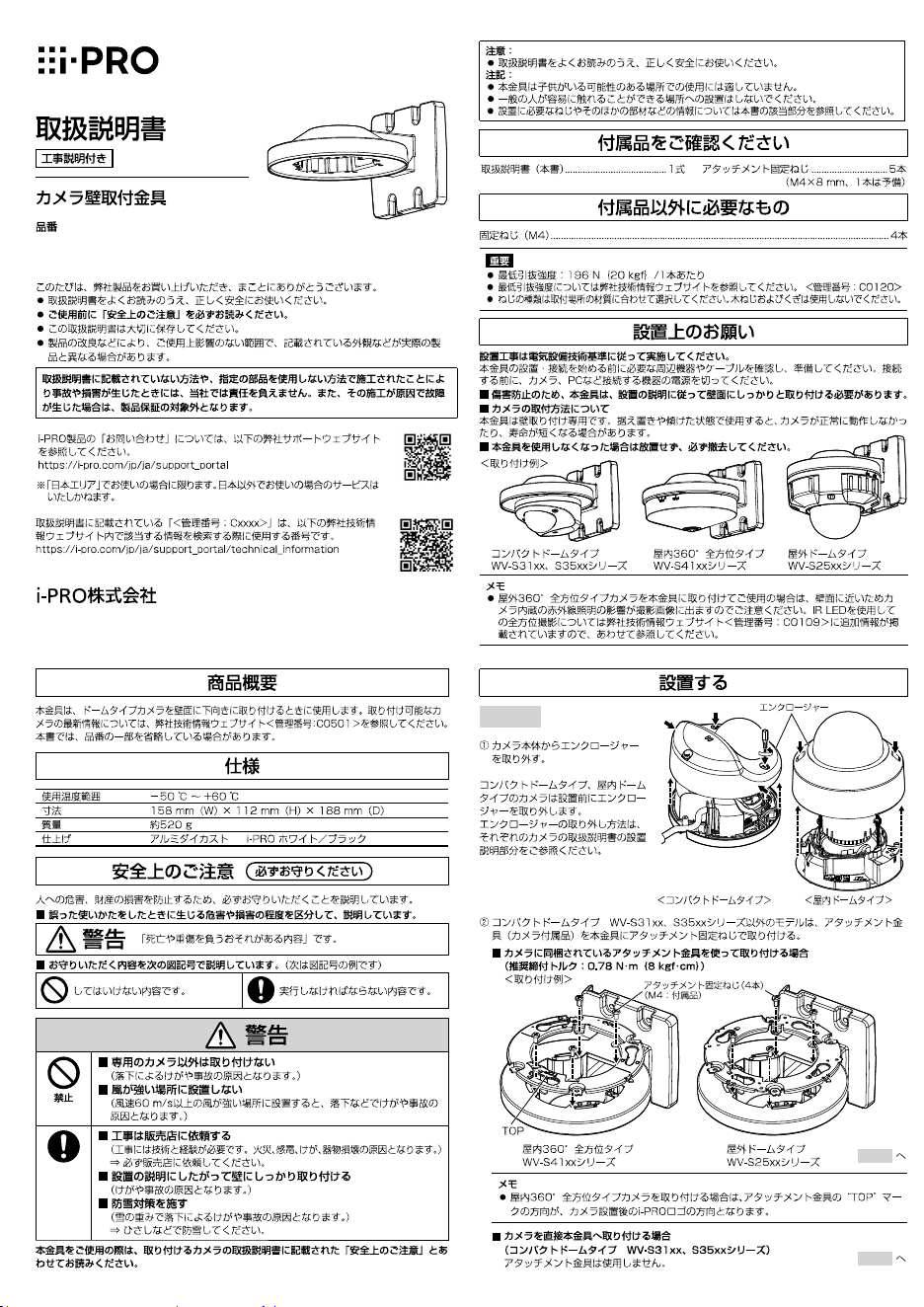
Mounting method for this product
This product is for attaching to a wall. If the product is mounted on a desktop or at a slant, the
camera may not work correctly and its lifetime may be shortened.
Make sure to remove this product if it will no longer be used.
Compact dome type
WV-S31xx, S35xx series
Indoor 360-degree panoramic type
WV-S41xx series
Outdoor dome type
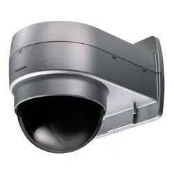
WV-S25xx series
NOTE
When an outdoor 360-degree panoramic type camera is attached using this product, it will be
close to the wall surface, so the infra-red light built into the camera will have an effect on the
images taken. For additional information on omnidirectional shooting using an IR LED, refer to
our technical information website <Control No.: C0109>.
<Installation example>
The installation instructions from hereon use the installation of the outdoor dome type camera on a
wall using this product as an example. The procedure for installation is the same for other cameras.
When installing by combining this product with other brackets, refer to the Operating Instructions for
the other brackets as well.
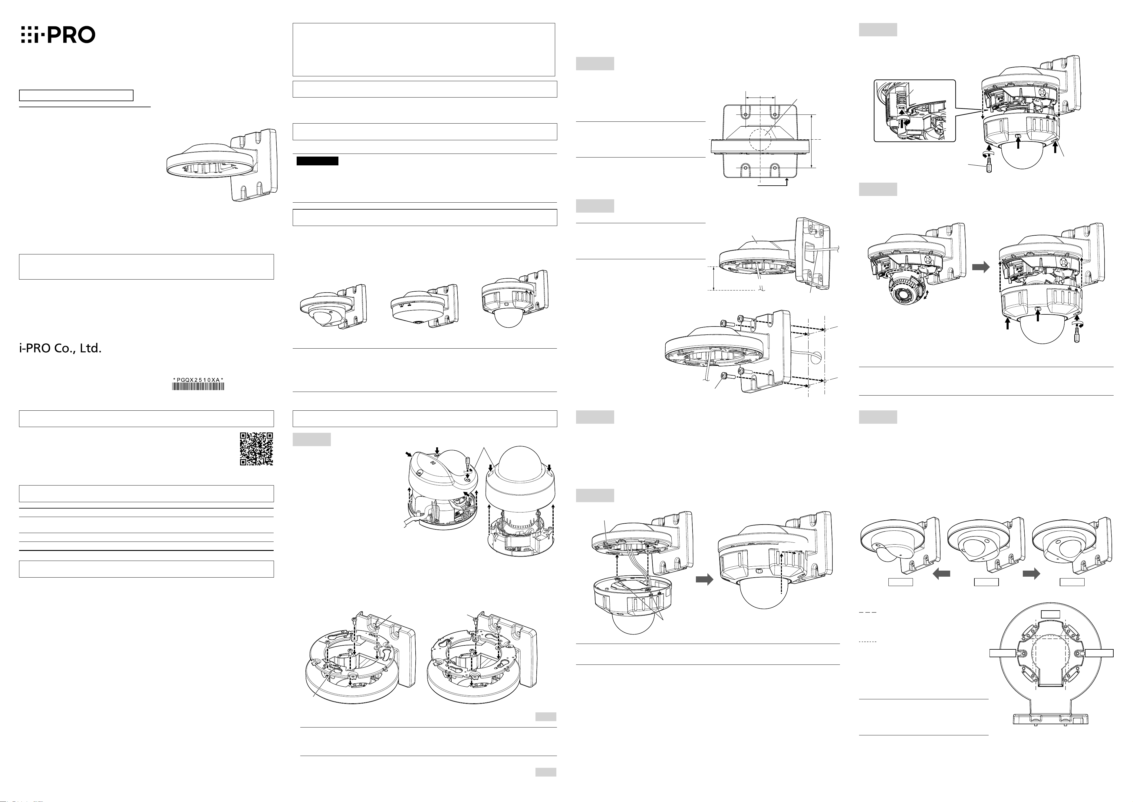
Step 2
Decide the location where this product is to be attached on the wall,
then make the holes for fixing and wiring as shown in the below
illustration.
* Determine the diameter and depth of the holes
according to the specifications of the fixing
screws (4 pcs.) (M4: procured separately).
NOTE
When wiring using the “wiring hole on the
side” of the camera, the “wiring hole” in the
illustration at right is not necessary.
Step 3
Thread the cables through this product, then fix to the wall.
NOTE
When installing outside, waterproof the
wiring hole and the holes for the fixing
screws.
Fixing screws (4 pcs.) (M4: locally procured)
Minimum pullout strength:
196 N {44 lbf} (per 1 pc.)
Wiring hole on the side
Wiring hole
ø30 mm
{1-3/16 inches}
46 mm
{1-13/16 inches}
83.5 mm
{3-9/32
inches}
This product
Cables
100 mm {3-15/16 inches}
Fixing screw
Step 6
Remove the camera enclosure (when installing a camera type
other than the indoor dome type), then tighten the camera fixing
screws (red) to fix the camera firmly.
Camera fixing
screw (red)
Enclosure fixing
screw (4 places)
Bit
(camera accessory)
Step 7
After adjusting the angular field of view of the camera, fix the
enclosure to the original position.
Refer to the Installation Guide for the camera for detailed
adjustment methods.
Recommended tightening torque
: 0.78 N·m {0.58 lbf·ft}
NOTE
The recommended tightening torque for the screws depends on the camera you are using.
Refer to the Installation Guide for each camera.
Step 4
Connect the cables to the camera.
When installing an outdoor dome type camera
Connect the cables to the camera. The cable connector is waterproofed. For details about this
treatment, refer to the operating instructions of the camera you are using.
When installing an indoor dome type camera
The waterproofing procedures are not necessary for indoor installations. Connect directly to the
camera.
Step 5
Attach the camera to this product and temporarily fix.
Approx. 15°
Holes of the attachment
plate (4 places)
Attachment mounting
screws (2 places)
NOTE
Refer to the Installation Guide for the camera for information on how to attach.
Step 8
Attaching the compact dome type WV-S31xx, S35xx series
Process the installation surface according to the description in Step 2.
Referring to the description in Step 3, thread the network cable through this product (the
attachment plate is not attached) to fix it in place.
Either connect the RJ45 waterproof connector according to Step 4, or for the indoor model,
attach the network cable directly to the camera.
Fix the camera to this product. The camera can be attached in the forward facing direction or
rotated at ±90° to the left or right. When shooting close to the wall, change the fixing position
by ±90° in either direction.
Refer to the Installation Guide for the camera for detailed attachment methods.
The following illustration shows an example of installing an indoor compact dome type
WV-S31xx series.
Left 90° Right 90°Front
<Positions for holes used for attachment>
Fixing positions for screws when using
an outdoor compact dome type
WV-S35xx series
(Front, rotated 90° left, rotated 90° right)
Fixing positions for screws when using
an indoor compact dome type
WV-S31xx series
(Front, rotated 90° left, rotated 90° right)
Recommended tightening torque
: 0.78 N·m {0.58 lbf·ft}
NOTE
When fixing a compact dome type camera,
of the three fixing positions, use the 2
forward places to fix.
Right 90°Left 90°
Front
Installation
Step 1
Remove the enclosure from the
camera body.
For compact dome types and indoor
dome types of cameras, the enclosure
is removed before installation.
Refer to the parts describing installation
in the Installation Guide for each
camera for information on how to
remove the enclosure.
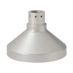
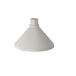
For models other than the compact dome type WV-S31xx, S35xx series, attach the attachment
plate (camera accessory) to this product using the fixing screws for attachment plate.
When attaching using the attachment plate included with the camera
(Recommended tightening torque: 0.78 N·m {0.58 lbf·ft})
<Installation example>
NOTE
When attaching an indoor 360-degree panoramic type camera, the “TOP” mark direction on the
attachment plate will be in the direction of the i-PRO logo after the camera is installed.
When attaching the camera directly to this product
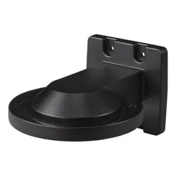
(Compact dome type WV-S31xx, S35xx series)
The attachment plate is not used.
Enclosure
<Compact dome type> <Indoor dome type>
Fixing screw for attachment plate
(4 pcs.) (M4: accessories)
Indoor 360-degree panoramic type
WV-S41xx series
Outdoor dome type
WV-S25xx series
Step 2
Step 8
Preface
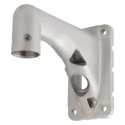
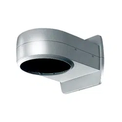
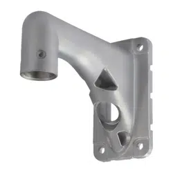
This product is used to attach dome-type cameras facing down on a wall.
For the latest information about the supported cameras, refer to our technical
information website
(https://i-pro.com/global/en/surveillance/training-support/support/technical-information
<Control No.: C0501>).
The model number is abbreviated in some descriptions in this manual.
Specifications
Ambient operating temperature: –50 °C to +60 °C {–58 °F to +140 °F}
Dimensions: 158 mm (W) × 112 mm (H) × 188 mm (D)
{6-7/32 inches (W) × 4-13/32 inches (H) × 7-13/32 inches (D)}
Mass: Approx. 520
g
{1.15 lbs}
Finish: Aluminum die cast i-PRO white/ Black/ Light gray
Precaution
Do not use this bracket except with suitable cameras.
Failure to observe this may cause a drop resulting in injury or accidents.
Do not install this product on a place that is greatly influenced by wind.
Installation on a place where the wind speed is 60 m/s {approx. 134 mph} or more may cause a
fall of the product resulting in injury or accidents.
Refer installation work to the dealer.
Installation work requires technique and experience. Failure to observe this may cause fire, electric
shock, injury, or damage to the product.
Be sure to consult the dealer.
Install the product securely on a wall in accordance with the installation instructions.
Failure to observe this may cause injury or accidents.
The measures of protection against snowfall shall be taken.
Weight of snow may cause a fall of the product resulting in injury or accidents.
Protect the product against snowfall by installing it under eaves.
When using this product, also read the “Precautions” described in the operating
instructions for the camera to be attached.
Operating Instructions
Included Installation Instructions
Wall Mount Bracket
Model No.
WV-QWL500
Before attempting to connect or install this product,
please read these instructions carefully and
save this manual for future use.
The external appearance and other parts shown in this manual may differ from the actual
product within the scope that will not interfere with normal use due to improvement of the
product.
i-PRO Co., Ltd. assumes no responsibility for injuries or property damage resulting
from failures arising out of improper installation or operation inconsistent with this
documentation.
© i-PRO Co., Ltd. 2023
avs1221-2013
Printed in China
https://www.i-pro.com/
TOP

Caution:
Before attempting to connect or operate this product, please read these instructions carefully.
Notice:
This product is not suitable for use in locations where children are likely to be present.
Do not install this product in locations where ordinary persons can easily reach.
For information about screws and other parts required for installation, refer to the
corresponding section of this document.
Standard accessories
Operating Instructions (this document) 1 pc. Fixing screws for attachment plate ............5 pcs.
(M4 x 8 mm {5/16 inches}) (of them, 1 for spare)
Other items that are needed (not included)
Fixing screws (M4) ..................................................................................................................... 4 pcs.
IMPORTANT
Minimum pullout strength: 196 N {44 lbf} (per 1 pc.)
This value indicates the minimum pull-out strength required value per screw.
For information
about the minimum pull-out strength, refer to our technical information website <Control No.: C0120>.
Select screws according to the material of the location that the camera will be mounted to.
In this case, wood screws and nails should not be used.
Precautions for installation
In order to prevent injury, the product must be securely mounted to the wall according to
the installation guide of this bracket.
Mounting method for this product
This product is for attaching to a wall. If the product is mounted on a desktop or at a slant, the
camera may not work correctly and its lifetime may be shortened.
Make sure to remove this product if it will no longer be used.
Compact dome type
WV-S31xx, S35xx series
Indoor 360-degree panoramic type
WV-S41xx series
Outdoor dome type
WV-S25xx series
NOTE
When an outdoor 360-degree panoramic type camera is attached using this product, it will be
close to the wall surface, so the infra-red light built into the camera will have an effect on the
images taken. For additional information on omnidirectional shooting using an IR LED, refer to
our technical information website <Control No.: C0109>.
<Installation example>
The installation instructions from hereon use the installation of the outdoor dome type camera on a
wall using this product as an example. The procedure for installation is the same for other cameras.
When installing by combining this product with other brackets, refer to the Operating Instructions for
the other brackets as well.
Step 2
Decide the location where this product is to be attached on the wall,
then make the holes for fixing and wiring as shown in the below
illustration.
* Determine the diameter and depth of the holes
according to the specifications of the fixing
screws (4 pcs.) (M4: procured separately).
NOTE
When wiring using the “wiring hole on the
side” of the camera, the “wiring hole” in the
illustration at right is not necessary.
Step 3
Thread the cables through this product, then fix to the wall.
NOTE
When installing outside, waterproof the
wiring hole and the holes for the fixing
screws.
Fixing screws (4 pcs.) (M4: locally procured)
Minimum pullout strength:
196 N {44 lbf} (per 1 pc.)
Wiring hole on the side
Wiring hole
ø30 mm
{1-3/16 inches}
46 mm
{1-13/16 inches}
83.5 mm
{3-9/32
inches}
This product
Cables
100 mm {3-15/16 inches}
Fixing screw
Step 6
Remove the camera enclosure (when installing a camera type
other than the indoor dome type), then tighten the camera fixing
screws (red) to fix the camera firmly.
Camera fixing
screw (red)
Enclosure fixing
screw (4 places)
Bit
(camera accessory)
Step 7
After adjusting the angular field of view of the camera, fix the
enclosure to the original position.
Refer to the Installation Guide for the camera for detailed
adjustment methods.
Recommended tightening torque
: 0.78 N·m {0.58 lbf·ft}
NOTE
The recommended tightening torque for the screws depends on the camera you are using.
Refer to the Installation Guide for each camera.
Step 4
Connect the cables to the camera.
When installing an outdoor dome type camera
Connect the cables to the camera. The cable connector is waterproofed. For details about this
treatment, refer to the operating instructions of the camera you are using.
When installing an indoor dome type camera
The waterproofing procedures are not necessary for indoor installations. Connect directly to the
camera.
Step 5
Attach the camera to this product and temporarily fix.
Approx. 15°
Holes of the attachment
plate (4 places)
Attachment mounting
screws (2 places)
NOTE
Refer to the Installation Guide for the camera for information on how to attach.
Step 8
Attaching the compact dome type WV-S31xx, S35xx series
Process the installation surface according to the description in Step 2.
Referring to the description in Step 3, thread the network cable through this product (the
attachment plate is not attached) to fix it in place.
Either connect the RJ45 waterproof connector according to Step 4, or for the indoor model,
attach the network cable directly to the camera.
Fix the camera to this product. The camera can be attached in the forward facing direction or
rotated at ±90° to the left or right. When shooting close to the wall, change the fixing position
by ±90° in either direction.
Refer to the Installation Guide for the camera for detailed attachment methods.
The following illustration shows an example of installing an indoor compact dome type
WV-S31xx series.
Left 90° Right 90°Front
<Positions for holes used for attachment>
Fixing positions for screws when using
an outdoor compact dome type
WV-S35xx series
(Front, rotated 90° left, rotated 90° right)
Fixing positions for screws when using
an indoor compact dome type
WV-S31xx series
(Front, rotated 90° left, rotated 90° right)
Recommended tightening torque
: 0.78 N·m {0.58 lbf·ft}
NOTE
When fixing a compact dome type camera,
of the three fixing positions, use the 2
forward places to fix.
Right 90°Left 90°
Front
Installation
Step 1
Remove the enclosure from the
camera body.
For compact dome types and indoor
dome types of cameras, the enclosure
is removed before installation.
Refer to the parts describing installation
in the Installation Guide for each
camera for information on how to
remove the enclosure.
For models other than the compact dome type WV-S31xx, S35xx series, attach the attachment
plate (camera accessory) to this product using the fixing screws for attachment plate.
When attaching using the attachment plate included with the camera
(Recommended tightening torque: 0.78 N·m {0.58 lbf·ft})
<Installation example>
NOTE
When attaching an indoor 360-degree panoramic type camera, the “TOP” mark direction on the
attachment plate will be in the direction of the i-PRO logo after the camera is installed.
When attaching the camera directly to this product
(Compact dome type WV-S31xx, S35xx series)
The attachment plate is not used.
Enclosure
<Compact dome type> <Indoor dome type>
Fixing screw for attachment plate
(4 pcs.) (M4: accessories)
Indoor 360-degree panoramic type
WV-S41xx series
Outdoor dome type
WV-S25xx series
Step 2
Step 8
Preface
This product is used to attach dome-type cameras facing down on a wall.
For the latest information about the supported cameras, refer to our technical
information website
(https://i-pro.com/global/en/surveillance/training-support/support/technical-information
<Control No.: C0501>).
The model number is abbreviated in some descriptions in this manual.
Specifications
Ambient operating temperature: –50 °C to +60 °C {–58 °F to +140 °F}
Dimensions: 158 mm (W) × 112 mm (H) × 188 mm (D)
{6-7/32 inches (W) × 4-13/32 inches (H) × 7-13/32 inches (D)}
Mass: Approx. 520
g
{1.15 lbs}
Finish: Aluminum die cast i-PRO white/ Black/ Light gray
Precaution
Do not use this bracket except with suitable cameras.
Failure to observe this may cause a drop resulting in injury or accidents.
Do not install this product on a place that is greatly influenced by wind.
Installation on a place where the wind speed is 60 m/s {approx. 134 mph} or more may cause a
fall of the product resulting in injury or accidents.
Refer installation work to the dealer.
Installation work requires technique and experience. Failure to observe this may cause fire, electric
shock, injury, or damage to the product.
Be sure to consult the dealer.
Install the product securely on a wall in accordance with the installation instructions.
Failure to observe this may cause injury or accidents.
The measures of protection against snowfall shall be taken.
Weight of snow may cause a fall of the product resulting in injury or accidents.
Protect the product against snowfall by installing it under eaves.
When using this product, also read the “Precautions” described in the operating
instructions for the camera to be attached.
Operating Instructions
Included Installation Instructions
Wall Mount Bracket
Model No.
WV-QWL500
Before attempting to connect or install this product,
please read these instructions carefully and
save this manual for future use.
The external appearance and other parts shown in this manual may differ from the actual
product within the scope that will not interfere with normal use due to improvement of the
product.
i-PRO Co., Ltd. assumes no responsibility for injuries or property damage resulting
from failures arising out of improper installation or operation inconsistent with this
documentation.
© i-PRO Co., Ltd. 2023
avs1221-2013
Printed in China
https://www.i-pro.com/
TOP
Step 2
Step 3
Step 6
Step 7
Step 4
Step 5
Step 8
Step 2
Step 3
Step 4
Step 1
Step 2
Step 8
WV-QWL500
https://www.i-pro.com/
Step 2
Step 3
Step 6
Step 7
Step 4
Step 5
Step 8
Step 2
Step 3
Step 4
Step 1
Step 2
Step 8
WV-QWL500
https://www.i-pro.com/