Loading ...
Loading ...
Loading ...
Version 23.00, November 2020
16 Rohde & Schwarz R&S
®
RTH1002, R&S
®
RTH1004 Handheld Oscilloscope
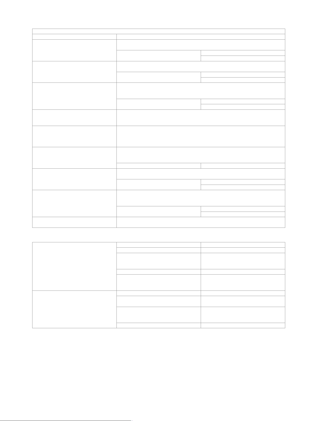
Trigger types
Edge
triggers on specified slope (positive, negative or either) and level
Glitch
triggers on glitches of positive, negative or either polaritiy that are shorter or longer
than specified width
glitch width
800 ps to 5000 s (CH1, CH2, CH3, CH4)
800 ps to 5000 s (D0 to D7)
Width
triggers on positive or negative pulse of specified width; width can be shorter, longer,
inside or outside the interval
pulse width
800 ps to 5000 s (CH1, CH2, CH3, CH4)
800 ps to 5000 s (D0 to D7)
Pattern
triggers when a logical combination (and, nand, or, nor) of the input channels stays true
for a period of time shorter, longer, inside or outside a specified range
(requires R&S
®
RTH-K19 option)
pattern time
800 ps to 5000 s (CH1, CH2, CH3, CH4)
800 ps to 5000 s (D0 to D7)
State
triggers when a logical combination (and, nand, or, nor) of the input channels stays true
at a slope (positive, negative or either) in one selected channel; state values may be
high (H), low (L) or don’t care (X) (requires R&S
®
RTH-K19 option)
Data2clock
triggers on setup time and hold time violations between clock and data present on any
two input channels; monitored time interval may be specified by the user with a step
size of 800 ps in the range from –124 ns to 124 ns around a clock edge
(requires R&S
®
RTH-K19 option)
Serial pattern
triggers on serial data pattern up to 32 bit clocked by one input channel; pattern bits
may be high (H), low (L) or don’t care (X); clock edge slope may be positive, negative
or either (requires R&S
®
RTH-K19 option)
max. data rate
< 250 Mbps
Timeout
triggers when signal stays high, low or unchanged for a specified period of time
(requires R&S
®
RTH-K19 option)
timeout
800 ps to 5000 s (CH1, CH2, CH3, CH4)
800 ps to 5000 s (D0 to D7)
Interval
triggers when time between two consecutive edges of same slope (positive or
negative) is shorter, longer inside or outside a specified range
(requires R&S
®
RTH-K19 option)
interval time
800 ps to 5000 s (CH1, CH2, CH3, CH4)
800 ps to 5000 s (D0 to D7)
Protocol
see R&S
®
RTH-K1, R&S
®
RTH-K2, R&S
®
RTH-K3, R&S
®
RTH-K9 and R&S
®
RTH-K10
options
Waveform measurements
Automatic measurements on
total number of active measurements
4
sources
logic channels from D0 to D7
time based measurements
period, frequency, positive pulse width,
negative pulse width, positive duty cycle,
negative duty cycle, delay, phase
amplitude based measurements
mean value
count based measurements
count positive pulses, count negative
pulses, count rising edges, count falling
edges
Cursor measurements
sources
logic channels from D0 to D7
vertical
2 cursors showing time, time difference
and inverse time difference (frequency)
tracking
vertical cursor additionally showing logic
level and logic level difference of selected
channel
measure
defines gate for automatic measurements
Loading ...
Loading ...
Loading ...