
This manual should be considered a permanent part of the vehicle
and should remain with the vehicle when it is resold.
This publication includes the latest production information available
before printing. Honda Motor Co., Ltd. reserves the right to make
changes at any time without notice and without incurring any
obligation.
No part of this publication may be reproduced without written
permission.
The vehicle pictured in this owner’s manual may not match your
actual vehicle.
© 2020 Honda Motor Co., Ltd.
Welcome
Congratulations on your purchase of a new
Honda vehicle. Your selection of a Honda
makes you part of a worldwide family of
satisfied customers who appreciate Honda's
reputation for building quality into every
product.
To ensure your safety and riding pleasure:
● Read this owner's manual carefully.
● Follow all recommendations and
procedures contained in this manual.
● Pay close attention to safety messages
contained in this manual and on the
vehicle.
● The following codes in this manual
indicate each country.
● The illustrations here in are based on the
WW125A KO type.
Country Codes
Code Country
WW125A
ED
European direct sales, UK,
France, Turkey
KO Korea
WW125
KO Korea
*The specifications may vary with each locale.
A Few Words About Safety
Your safety, and the safety of others, is very
important. Operating this vehicle safely is an
important responsibility.
To help you make informed decisions about
safety, we have provided operating
procedures and other information on safety
labels and in this manual. This information
alerts you to potential hazards that could
hurt you or others.
Of course, it is not practical or possible to
warn you about all hazards associated with
operating or maintaining a vehicle. You must
use your own good judgement.
You will find important safety information in a
variety of forms, including:
● Safety labels on the vehicle
●
Safety Messages preceded by a safety alert
symbol and one of three signal words:
DANGER, WARNING, or CAUTION.
These signal words mean:
3DANGER
You WILL be KILLED or SERIOUSLY HURT
if you don’t follow instructions.
3WARNING
You CAN be KILLED or SERIOUSLY HURT
if you don’t follow instructions.
3CAUTION
You CAN be HURT if you don’t follow
instructions.
Other important information is
provided under the following titles:
NOTICE
Information to help you avoid
damage to your vehicle, other
property, or the environment.

Safety Guidelines................................................. P. 3
Image Labels......................................................... P. 6
Safety Precautions............................................. P. 10
Riding Precautions ............................................ P. 11
Accessories & Modifications...........................P. 15
Loading ................................................................ P. 16
This section contains important information for safe riding of your vehicle.
Please read this section carefully.
Vehicle Safety

Safety Guidelines
Follow these guidelines to enhance your safety:
● Perform all routine and regular inspections
specified in this manual.
● Stop the engine and keep sparks and flame
away before filling the fuel tank.
● Do not run the engine in enclosed or partly
enclosed areas. Carbon monoxide in
exhaust gases is toxic and can kill you.
Always Wear a Helmet
It's a proven fact: helmets and protective
apparel significantly reduce the number and
severity of head and other injuries. So always
wear an approved helmet and protective
apparel. 2 P. 10
Before Riding
Make sure that you are physically fit, mentally
focused and free of alcohol and drugs. Check
that you and your passenger are both wearing
an approved helmet and protective apparel.
Instruct your passenger on holding onto the
grab rail or your waist, leaning with you in turns,
and keeping their feet on the footpegs, even
when the vehicle is stopped.
Take Time to Learn & Practice
Even if you have ridden other vehicles, practice
riding in a safe area to become familiar with
how this vehicle works and handles, and to
become accustomed to the vehicle's size and
weight.
Ride Defensively
Always pay attention to other vehicles around
you, and do not assume that other drivers see
you. Be prepared to stop quickly or perform an
evasive maneuver.
Safety Guidelines
Vehicle Safety
3
Continued

Make Yourself Easy to See
Make yourself more visible, especially at night,
by wearing bright reflective clothing, positioning
yourself so other drivers can see you, signaling
before turning or changing lanes, and using
your horn when necessary.
Ride within Your Limits
Never ride beyond your personal abilities or
faster than conditions warrant. Fatigue and
inattention can impair your ability to use good
judgement and ride safely.
Don't Drink or Use Drugs and Ride
Alcohol or drugs and riding don't mix. Even one
alcoholic drink can reduce your ability to
respond to changing conditions, and your
reaction time gets worse with every additional
drink. The same is true for drug use. Don't drink
or use and ride, and don't let your friends do it
either.
Keep Your Honda in Safe Condition
It's important to keep your vehicle properly
maintained and in safe riding condition.
Inspect your vehicle before every ride and
perform all recommended maintenance. Never
exceed load limits (2 P. 16), and do not modify
your vehicle or install accessories that would
make your vehicle unsafe (2 P. 15).
If You are Involved in a Crash
Personal safety is your first priority. If you or
anyone else has been injured, take time to
assess the severity of the injuries and whether it
is safe to continue riding. Call for emergency
assistance if needed. Also follow applicable laws
and regulations if another person or vehicle is
involved in the crash.
Safety Guidelines
Vehicle Safety
4
If you decide to continue riding, first turn the
ignition switch to the (Off) position, and
evaluate the condition of your vehicle. Inspect
for fluid leaks, check the tightness of critical nuts
and bolts, and check the handlebar, control
levers, brakes, and wheels. Ride slowly and
cautiously.
Your vehicle may have suffered damage that is
not immediately apparent. Have your vehicle
thoroughly checked at a qualified service facility
as soon as possible.
Carbon Monoxide Hazard
Exhaust contains poisonous carbon monoxide, a
colourless, odorless gas. Breathing carbon
monoxide can cause loss of consciousness and
may lead to death.
If you run the engine in confined or even partly
enclosed area, the air you breathe could
contain a dangerous amount of carbon
monoxide.
Never run your vehicle inside a garage or other
enclosure.
3WARNING
Running the engine of your vehicle
while in an enclosed or even partially
enclosed area can cause a rapid build-
up of toxic carbon monoxide gas.
Breathing this colourless, odorless gas
can quickly cause unconsciousness and
lead to death.
Only run your vehicle's engine when it
is located in a well ventilated area
outdoors.
Safety Guidelines
Vehicle Safety
5
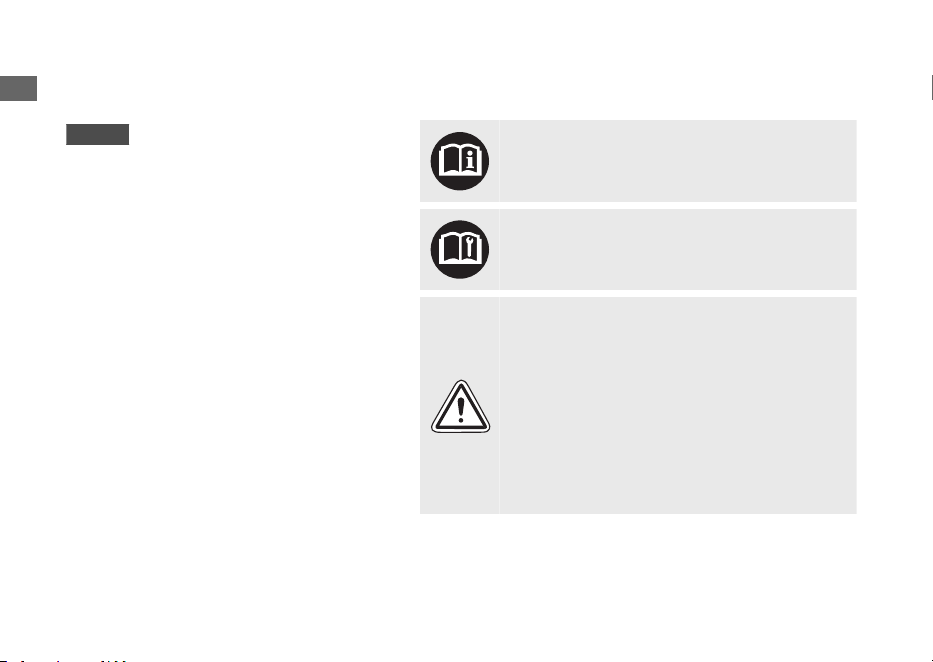
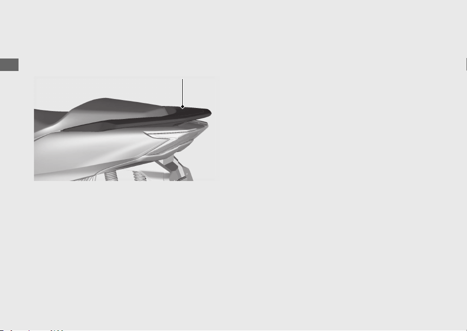
Image Labels
ED type
The following pages describe the label
meanings. Some labels warn you of
potential hazards that could cause serious
injury. Others provide important safety
information. Read this information carefully
and don't remove the labels.
If a label comes off or becomes hard to
read, contact your dealer for a replacement.
There is a specific symbol on each label.
The meanings of each symbol and label are
as follows.
Read instructions contained in Owner's
Manual carefully.
Read instructions contained in Shop Manual
carefully. In the interest of safety, take the
vehicle to be serviced only by your dealer.
DANGER (with RED background)
You WILL be KILLED or SERIOUSLY HURT if
you don't follow instructions.
WARNING (with ORANGE background)
You CAN be KILLED or SERIOUSLY HURT if
you don't follow instructions.
CAUTION (with YELLOW background)
You CAN be HURT if you don't follow
instructions.
Image Labels
Vehicle Safety
6
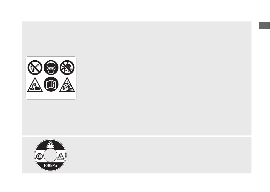
BATTERY LABEL
DANGER
• Keep flame and spark away from the battery. Battery produce
explosive gas that can cause explosion.
• Wear the eye protection and rubber gloves when handling the battery,
or you can get burned or lose your eyesight by the battery electrolyte.
• Do not allow children and other people to touch a battery unless they
understand proper handling and hazards of the battery very well.
• Handle the battery electrolyte with extreme care as it contains dilute
sulfuric acid. Contact with your skin or eyes can burn you or cause loss
of your eyesight.
• Read this manual carefully and understand it before handling the
battery. Neglect of the instructions can cause personal injury and
damage to the vehicle.
• Do not use a battery with the electrolyte at or below the lower level
mark. It can explode causing serious injury.
RADIATOR CAP LABEL
DANGER
NEVER OPEN WHEN HOT.
Hot coolant will scald you.
Relief pressure valve begins to open at 108 kPa.
Image Labels
Vehicle Safety
7
Continued
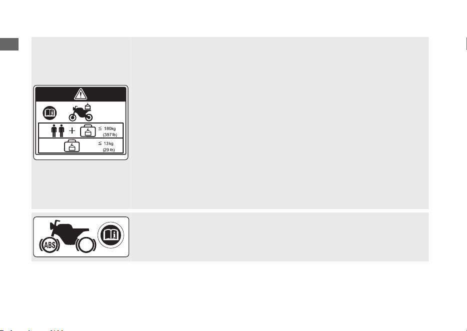
ACCESSORIES AND LOADING WARNING LABEL
WARNING
ACCESSORIES AND LOADING
• The safety stability and handling of this vehicle may be affected by the
addition of accessories and luggage.
• Read carefully the instructions contained in user's manual and
installation guide before installing any accessory.
• The total weight of accessories and luggage added to rider's and
passenger's weight should not exceed 180 kg (397 lb), which is the
maximum weight capacity.
• The luggage weight must not exceed 13 kg (29 lb) under any
circumstances.
•
The fitting of large fork-mounted or large handlebar mounted fairing is
not recommended.
ABS INFORMATION LABEL
This model equipped with an Anti-lock Brake System (ABS) on front wheel.
Image Labels
Vehicle Safety
8
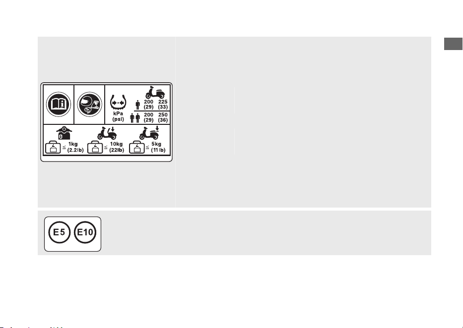
TYRE INFORMATION & CARGO LIMIT LABEL
For your protection, always wear helmet, protective apparel.
Cold tyre pressure:
[Driver only]
Front
Rear
200 kPa (2.00 kgf/cm
2
, 29 psi)
225 kPa (2.25 kgf/cm
2
, 33 psi)
[Driver and passenger]
Front
Rear
200 kPa (2.00 kgf/cm
2
, 29 psi)
250 kPa (2.50 kgf/cm
2
, 36 psi)
Cargo limit:
Front box
Centre compartment
Rear carrier
1.0 kg (2.2 lb)
10 kg (22 lb)
5 kg (11 lb)
FUEL LABEL
Unleaded petrol only
ETHANOL up to 10 % by volume
Image Labels
Vehicle Safety
9

Safety Precautions
● Ride cautiously and keep your hands on the
handlebar and feet on the step board.
● Keep passenger's hands onto the grab rail
or your waist, passenger's feet on the
footpegs while riding.
● Always consider the safety of your
passenger, as well as other drivers and
riders.
Protective Apparel
Make sure that you and any passenger are
wearing an approved helmet, eye protection,
and high-visibility protective clothing. Avoid
wearing loose clothes that could get caught on
any part of the vehicle. Ride defensively in
response to weather and road conditions.
#
Helmet
Safety-standard certified, high-visibility, correct
size for your head
●
Must fit comfortably but securely, with the
chin strap fastened.
●
Face shield with unobstructed field of vision
or other approved eye protection
3WARNING
Not wearing a helmet increases the
chance of serious injury or death in a
crash.
Make sure that you and any passenger
always wear an approved helmet and
protective apparel.
#
Gloves
Full-finger leather gloves with high abrasion
resistance
#
Boots or Riding Shoes
Sturdy boots with non-slip soles and ankle
protection
#
Jacket and Trousers
Protective, highly visible, long-sleeved jacket
and durable trousers for riding (or a protective
suit)
Safety Precautions
Vehicle Safety
10

Riding Precautions
Running-in Period
During the first 500 km (300 miles) of running,
follow these guidelines to ensure your vehicle's
future reliability and performance.
● Avoid full-throttle starts and rapid
acceleration.
● Avoid hard braking.
● Ride conservatively.
Brakes
Observe the following guidelines:
●
Avoid excessively hard braking.
u Sudden braking can reduce the vehicle's
stability.
u Where possible, reduce speed before
turning; otherwise you risk sliding out.
● Exercise caution on low traction surfaces.
u The tyres slip more easily on such
surfaces and braking distances are
longer.
● Avoid continuous braking.
u Repeated braking, such as when
descending long, steep slopes can
seriously overheat the brakes, reducing
their effectiveness.
● For full braking effectiveness, operate both
the front and rear brakes together.
#
Anti-lock Brake System (ABS) on Front
Wheel
WW125A
This model equipped with an Anti-lock Brake
System (ABS) designed to help prevent the front
brake from locking up during hard braking.
● There is no ABS function to the rear wheel.
● ABS does not reduce braking distance. In
certain circumstances, ABS may result in a
longer stopping distance.
Riding Precautions
Vehicle Safety
11
Continued

● ABS does not function at speeds below
10 km/h (6 mph).
● The front brake lever may recoil slightly
when applying the brakes. This is normal.
● Always use the recommended front/rear
tires to ensure correct ABS operation.
#
Combi Brake
WW125
Your vehicle is equipped with a brake system
that distributes the braking force between the
front and rear brakes.
The distribution of the braking force applied to
the front and rear brakes when operating the
front brake lever only and when operating the
rear brake lever only is different.
For full braking effectiveness, operate both the
front and rear brakes together.
#
Wet or Rainy Conditions
Road surfaces are slippery when wet, and wet
brakes further reduce braking efficiency.
Exercise extra caution when braking in wet
conditions.
If the brakes get wet, apply the brakes while
riding at low speed to help them dry.
Parking
●
Park on a firm, level surface.
●
If you must park on a slight incline or loose
surface, park so that the vehicle cannot
move or fall over.
● Make sure that high-temperature parts
cannot come into contact with flammable
materials.
● Do not touch the engine, muffler, brakes
and other high-temperature parts until they
cool down.
Riding Precautions
Vehicle Safety
12
● To reduce the likelihood of theft, always lock
the handlebar, lock the ignition switch
(2 P. 53) and leave your vehicle while taking
the Honda SMART Key with you. Deactivate
the Honda SMART Key system if necessary.
2 P. 48
Use of an anti-theft device is also
recommended.
Also set the anti-theft alarm system.
#
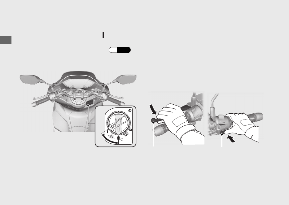
Parking with the Side Stand or Centre
Stand
1.
Stop the engine.
2.
Using the side stand
Push the side stand down.
Slowly lean the vehicle to the left until its
weight rests on the side stand.
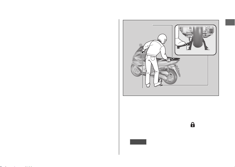
Using the centre stand
To lower the centre stand, stand on the left
side of the vehicle.
Hold the left handle grip and the grab rail.
Press down on the tip of the centre stand with
your right foot and, simultaneously, pull up and
back.
3.
Turn the handlebar fully to the left.
u Turning the handlebar to the right
reduces stability and may cause the
vehicle to fall.
4.
Turn the ignition switch to the (Lock)
position (2 P. 46) and lock the ignition
switch (2 P. 53).
5.
KO type
Set the anti-theft alarm system. 2 P. 55
Riding Precautions
Vehicle Safety
13
Continued
Left handle grip
Grab rail
Centre stand

Refuelling and Fuel Guidelines
Follow these guidelines to protect the engine,
fuel system and catalytic converter:
● Use only unleaded petrol.
● Use recommended octane number. Using
lower octane petrol will result in decreased
engine performance.
● Do not use fuels containing a high
concentration of alcohol. 2 P. 160
● Do not use stale or contaminated petrol or
an oil/petrol mixture.
● Avoid getting dirt or water in the fuel tank.
Honda selectable torque control
WW125A
When the Honda selectable torque control
(Torque Control) detects rear wheel spin during
acceleration, the system will limit the amount of
torque applied to the rear wheel.
Torque Control does not work during
deceleration and will not prevent the rear wheel
from skidding due to engine braking. Do not
close the throttle suddenly, especially when
riding on slippery surfaces.
Torque Control may not compensate for rough
road conditions or rapid throttle operation.
Always consider road and weather conditions,
as well as your skills and condition, when
applying throttle.
If your vehicle gets stuck in mud, snow or sand,
it may be easier to free it by turning off the
Torque Control temporarily.
Temporarily turning off Torque Control also
may help you maintain control and balance
when riding on off-road terrain.
The specified tyres must be used so that the
Torque Control can function correctly.
Riding Precautions
Vehicle Safety
14

Accessories &
Modifications
We strongly advise that you do not add any
accessories that were not specifically designed
for your vehicle by Honda or make
modifications to your vehicle from its original
design. Doing so can make it unsafe.
Modifying your vehicle may also void your
warranty and make your vehicle illegal to
operate on public roads. Before deciding to
install accessories on your vehicle be certain the
modification is safe and legal.
3WARNING
Improper accessories or modifications
can cause a crash in which you can be
seriously hurt or killed.
Follow all instructions in this owner's
manual regarding accessories and
modifications.
Do not pull a trailer with, or attach a sidecar to,
your vehicle. Your vehicle was not designed for
these attachments, and their use can seriously
impair your vehicle's handling.
Accessories & Modifications
Vehicle Safety
15
Loading
● Carrying extra weight affects your vehicle's
handling, braking and stability.
Always ride at a safe speed for the load you
are carrying.
● Avoid carrying an excessive load and keep
within specified load limits.
Maximum weight capacity / Maximum
luggage weight 2 P. 162
● Tie all luggage securely, evenly balanced
and close to the centre of the vehicle.
● Do not place objects near the lights or the
muffler.
3WARNING
Overloading or improper loading can
cause a crash and you can be seriously
hurt or killed.
Follow all load limits and other loading
guidelines in this manual.
Loading
Vehicle Safety
16

Vehicle Safety
17
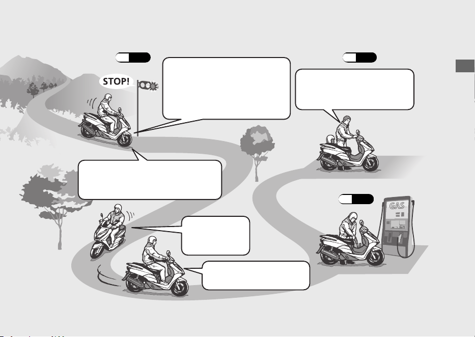
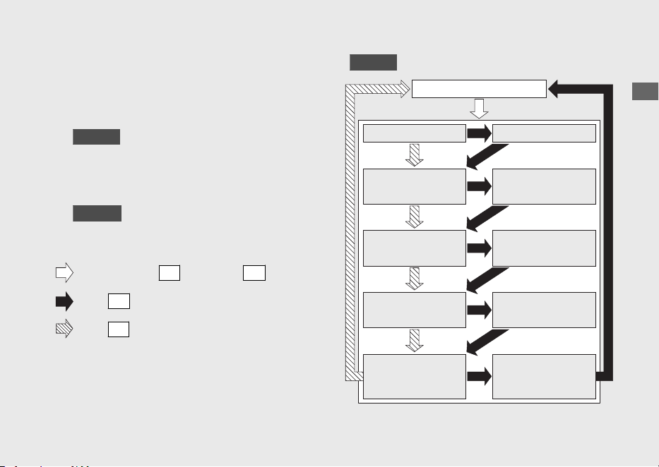
Basic Operation Flow
Operation Guide
18
#
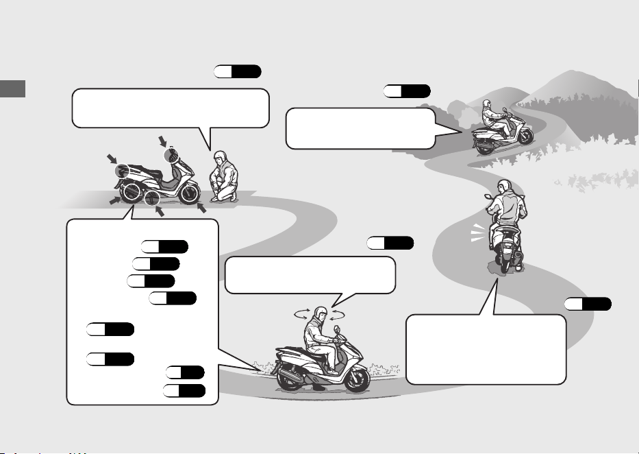
Pre-ride Inspection (P.92)
Carefully inspect your vehicle to
make sure that it is safe to ride.
#
Acceleration (P.76)
Apply throttle gradually.
Obey the speed limit.
How to use basic features.
• Instruments (P.26)
• Indicators (P.40)
• Switches (P.44)
• Steering Lock (P.46)
#
Starting the Engine (P.73)
Start and warm the engine.
Avoid revving the engine.
#
Starting the
Vehicle (P.76)
Before pulling away, indicate your
direction with the turn signal
switch, and check for oncoming
traffic.
• Honda SMART Key System
(P.47)
• Anti-theft Alarm System
(P.55)
•
Answer Back System (P.61)
•
Idling Stop System (P.69)
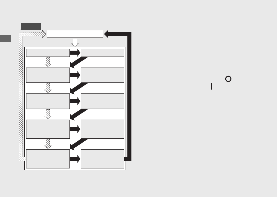
Operation Guide
19
#
Braking (P.77)
Close the throttle and apply the
front and rear brakes together.
u
The brakelight will indicate that
you have applied the brakes.
#
Parking (P.12)
#
Stopping
If pulling off the road, signal early
enough to show traffic that you are
pulling over, and pull over smoothly.
#
Turning Corners
Do your braking
before entering
corners.
Gradually reapply throttle
when exiting turn.
#
Refuelling (P.78)
Park on a firm level surface.
Use the stand, lock the steering.
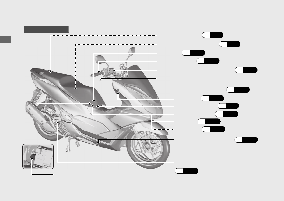
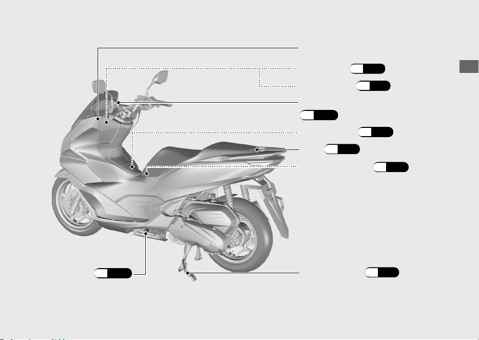
Parts Location
Operation Guide
20
Throttle grip (P.120)
Document bag (P.84)
Front brake fluid reservoir (P.112)
Tool kit (P.102)
Front brake lever
Engine oil fill cap/dipstick
(P.106
)
Fuse box (P.143)
Centre compartment (P.84)
Battery (P.103)
Coolant reserve tank
(P.108)
Battery cover (P.104)
Data link connector
WW125A ED type
Emergency seat opener (P.137)
Front lid (P.105)
Helmet holder (P.83)
Operation Guide
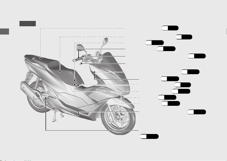
22
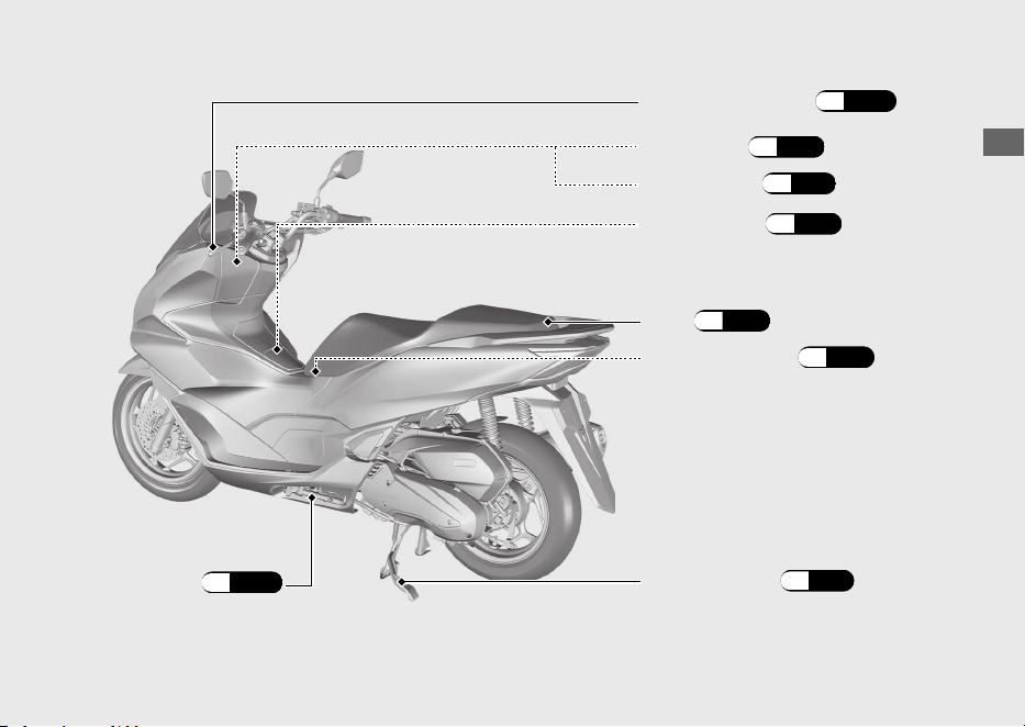
Parts Location (Continued)
Throttle grip (P.120)
Document bag (P.84)
Front brake fluid reservoir (P.110)
Tool kit (P.102)
Front brake lever
Engine oil fill cap/dipstick
(P.106
)
Fuse box (P.143)
Centre compartment (P.84)
Battery (P.103)
Battery cover (P.104)
WW125A KO type
Emergency seat opener (P.137)
Coolant reserve tank
(P.108)
Helmet holder (P.83)
Front lid (P.105)
Operation Guide
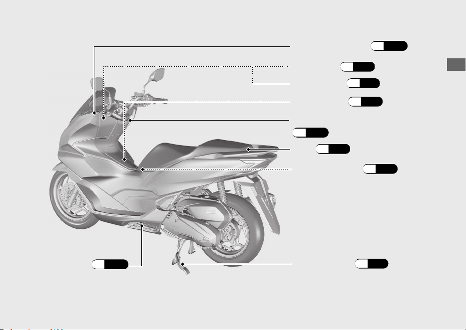
24
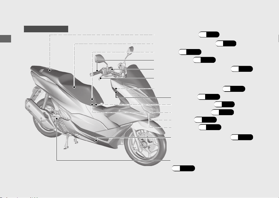
Parts Location (Continued)
Front brake lever
Engine oil fill cap/dipstick
(P.106
)
Fuse box (P.143)
Battery (P.103)
Battery cover (P.104)
Emergency seat opener (P.137)
WW125
Coolant reserve tank
(P.108)
Centre compartment (P.84)
Tool kit (P.102)
Front brake fluid reservoir (P.110)
Document bag (P.84)
Throttle grip (P.120)
Helmet holder (P.83)
Front lid (P.105)
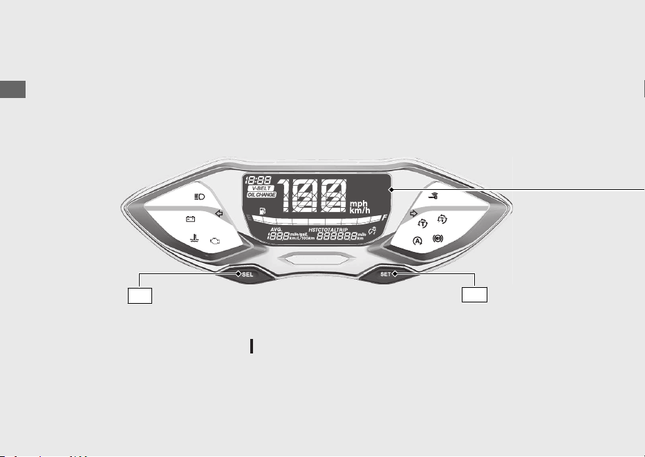
Instruments
Operation Guide
26
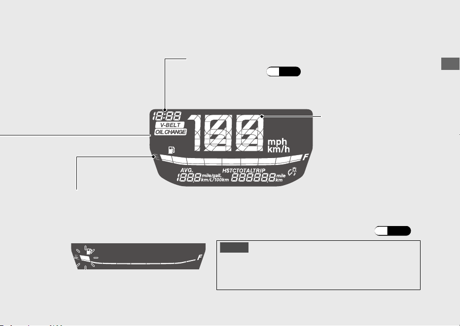
Display Check
When the ignition switch is turned (On), initial animation will show.
SEL
switch
If any part of these displays does not come on when it should, have your dealer check for
problems.
SET
switch
Operation Guide
27
Continued
If the fuel gauge indicator flashes in a repeat pattern or turns off: (P.131)
Remaining fuel when only 1st (E) segment starts flashing
approximately: 0.9 L (0.24 US gal, 0.20 Imp gal)
Fuel gauge
Clock (12-hour display)
To set the clock: (P.33)
Speedometer
NOTICE
You should refuel when the reading approaches the
1st (E) segment. Running out of fuel can cause the
engine to misfire, damaging the catalytic converter.
Operation Guide
28
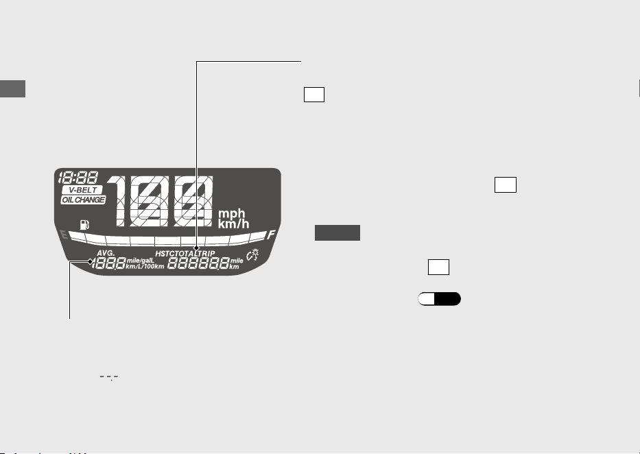
Instruments (Continued)
Odometer [TOTAL] , Tripmeter [TRIP] &
Torque Control [HSTC]
SEL
switch selects the odometer, tripmeter and
Torque Control.
•
Odometer:
•
Tripmeter:
Distance ridden since tripmeter was reset.
To reset tripmeter, press and hold
SET
switch
with tripmeter displayed.
Total distance ridden.
The average fuel mileage is also reset.
Average fuel mileage meter [AVG]
The average fuel mileage will be based on tripmeter.
Average fuel mileage since tripmeter was reset.
When “ ” is displayed except after the average fuel
mileage has been reset, go to your dealer for service.
•
WW125A
Torque Control:
Pressing and holding
SET
switch while
Torque Control is displayed turns Torque
Control on and off. (P.72)
Operation Guide
29
Continued
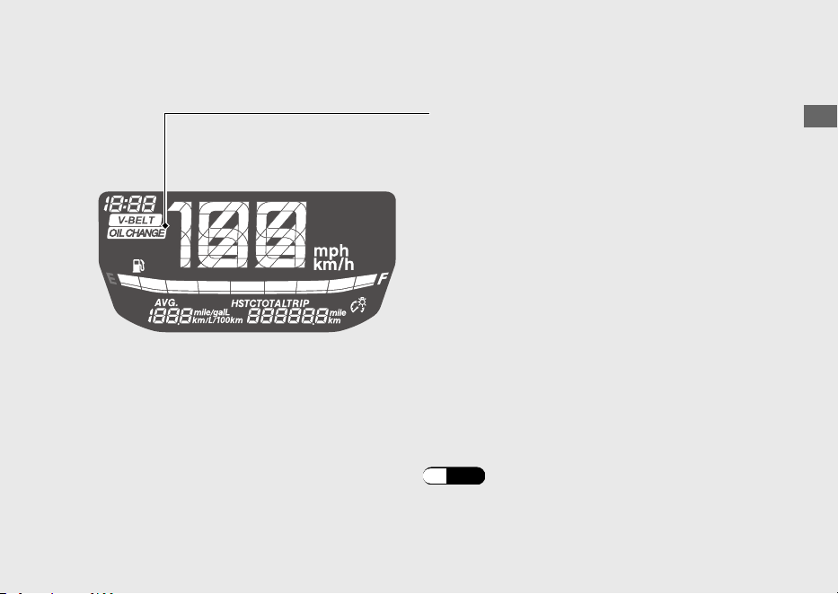
If the oil is changed before the oil change indicator comes on, be sure to reset the oil
change indicator after changing the oil.
The indicator does not go off until it is reset.
OIL CHANGE indicator
The indicator is turned on whenever the
running distance reaches the programmed oil
change interval.
When the running distance reaches about
1,000 km (600 miles):
Reset the indicator for the 1st time.
When the running distance reaches about
every 6,000 km (4,000 miles) after the 1st time
resetting:
Reset the indicator whenever it is turned on.
After changing the engine oil, be sure to reset
the indicator.
How to Reset the OIL CHANGE Indicator: (P.36)
Operation Guide
30
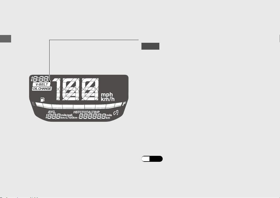
Instruments (Continued)
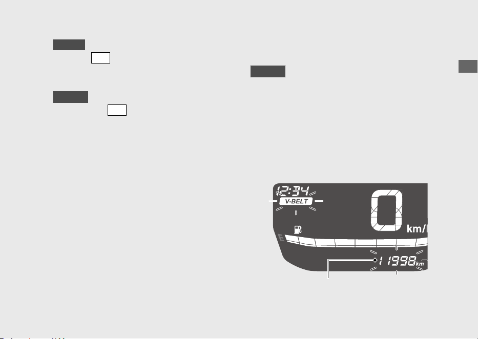
If the belt is inspected or replaced before the
V-BELT indicator comes on, be sure to reset
the indicator after inspecting or replacing the
belt.
The indicator does not go off until it is reset.
V-BELT indicator
KO type
The indicator turns on when the running
distance reaches the set distance.
How to Reset the V-BELT Indicator:
(P.38
)
The indicator turns on when the running
distance reaches about 12,000 km (8,000
miles) since the last reset.
Reset the indicator whenever it is turned on.
After inspecting or replacing the belt, be
sure to reset the indicator.
Display Setting
Following items can be changed sequentially.
• Clock setting
• Backlight brightness adjustment
•
ED type
Changing of speed and mileage unit
• Changing of fuel mileage meter unit
• Resetting OIL CHANGE indicator
•
KO type
Resetting V-BELT indicator
Operation Guide
31
Continued
Press and hold
SEL
switch and
SET
switch
Press
SET
switch
Press
SEL
switch
Ordinary display
Clock setting mode
Backlight brightness
adjustment mode
Changing of fuel mileage
meter unit mode
Clock setting
Backlight brightness
adjustment
Changing of fuel
mileage meter unit
ED type
Changing of speed and
mileage unit mode
Changing of speed
and mileage unit
Running distance until
OIL CHANGE indicator
lights display mode
Resetting OIL
CHANGE indicator
The following moves the ordinary display at
display setting.
● The switch is not pressed for about 30
seconds
u The items that are being set are deleted,
and only the items whose settings have
been completed are reflected.
● Turn the ignition switch to the (Off)
position and then to the
(On) position
u The items that are being set and the
items whose settings have been
completed are reflected.
Operation Guide
32
Instruments (Continued)
Ordinary display
Clock setting mode
Backlight brightness
adjustment mode
Changing of fuel mileage
meter unit mode
Clock setting
Backlight brightness
adjustment
Changing of fuel
mileage meter unit
KO type
Running distance until
OIL CHANGE indicator
lights display mode
Resetting OIL
CHANGE indicator
Running distance until
V-BELT indicator
lights display mode
Resetting V-BELT
indicator
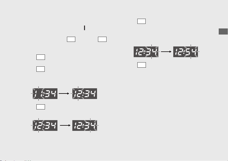
1 Clock setting:
a
Turn the ignition switch to the (On)
position.
b
Pressing and holding
SEL
switch and
SET
switch makes the hour and minute displays
start flashing.
c
Press
SET
switch, the hour digits start
flashing.
d
Press
SEL
switch until the desired hour is
displayed.
u Press and hold to advance the hour fast.
e
Press
SET
switch. The minute digits start
flashing.
f
Press
SEL
switch until the desired minute is
displayed.
u Press and hold to advance the minute
fast.
g
Press
SET
switch. The clock is set, and then
the display moves to the backlight
brightness adjustment. (backlight brightness
indicator and backlight brightness
adjustment segments start flashing.)
Operation Guide
33
Continued
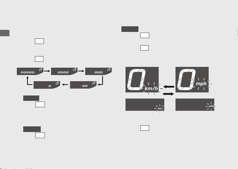
2 Backlight brightness adjustment:
You can adjust the brightness to one of five
levels.
a
Press
SET
switch, the backlight brightness
indicator and backlight brightness
adjustment segments flash faster.
b
Press
SEL
switch. The brightness is switched.
c
ED type
Press
SET
switch. The backlight is set, and
then the display moves to the changing of
speed and mileage unit. (speed and
mileage unit start flashing.)
KO type
Press
SET
switch. The backlight is set, and
then the display moves to the changing of
the fuel mileage meter unit. (fuel mileage
meter unit start flashing.)
3 Changing of speed and mileage unit:
ED type
a
Press
SET
switch, the speed and mileage
unit start flashing fast.
b
Press
SEL
switch to select either “km/h” and
“km” or “mph” and “mile”.
c
Press
SET
switch. The speed and mileage
unit is set, and then the display moves to the
changing of fuel mileage meter unit. (fuel
mileage meter unit start flashing.)
Operation Guide
34
Instruments (Continued)
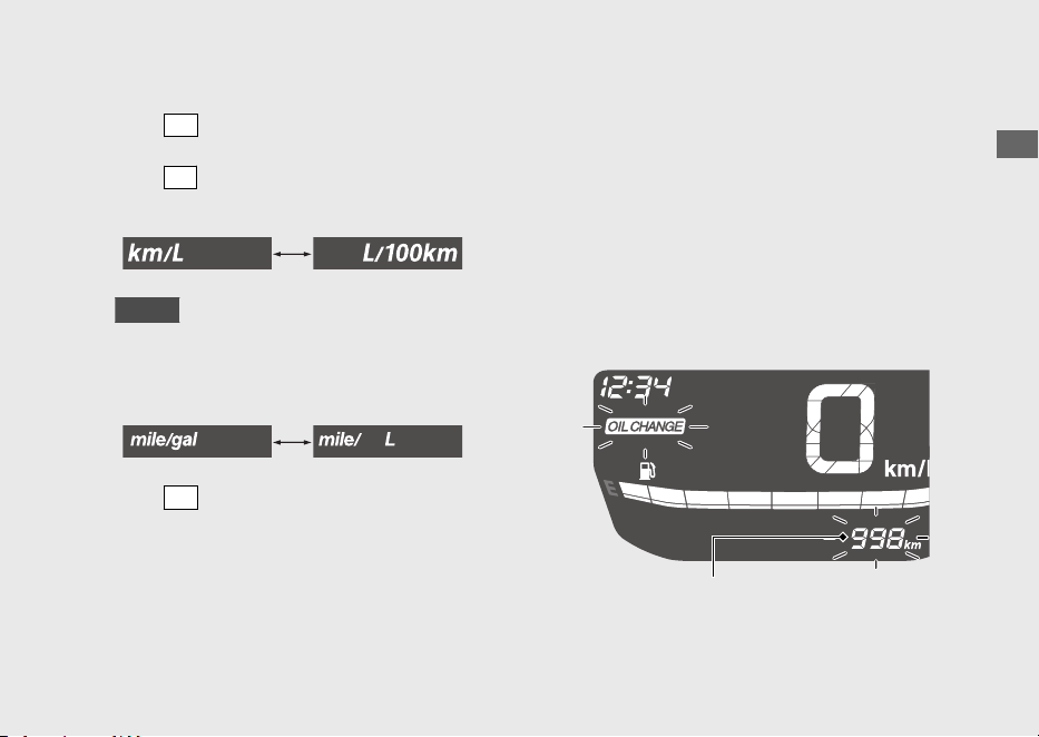
4 Changing the fuel mileage meter unit:
a
Press
SET
switch, the fuel mileage meter unit
start flashing fast.
b
Press
SEL
switch to select “km/L” or “L/100
km”.
ED type
If the “mph” for speed and “mile” for
mileage are selected, the fuel mileage
shown by “mile/L” or “mile/gal”.
c
Press
SET
switch. The fuel mileage meter unit
is set, and then the display moves to running
distance until OIL CHANGE indicator lights.
(OIL CHANGE indicator starts flashing.)
5 Running distance until OIL CHANGE
indicator lights display:
You can confirm the running distance until
the OIL CHANGE indicator lights, and then
reset the OIL CHANGE indicator.
#
Confirming the running distance until
OIL CHANGE indicator lights
Display the running distance until the OIL
CHANGE indicator lights.
Operation Guide
35
Continued
Running distance until
OIL CHANGE indicator lights
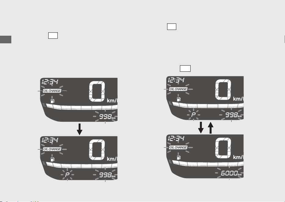
#
Resetting OIL CHANGE indicator
a
Pressing
SET
switch causes the OIL CHANGE
indicator, and the running distance until the
OIL CHANGE indicator lights, to flash.
u “P” flashes when the running distance
until the OIL CHANGE indicator lights is
displayed.
b
Press
SEL
switch to select oil change interval.
u “P” turns off when the oil change interval
is displayed.
u When the running distance until the OIL
CHANGE indicator lights is displayed, the
OIL CHANGE indicator does not reset
even if
SET
switch is pressed.
Operation Guide
36
Instruments (Continued)
c
ED type
Pressing
SET
switch resets the OIL
CHANGE indicator. When this is reset, the
display changes to normal.
KO type
Pressing the
SET
switch resets the OIL
CHANGE indicator. When this is reset, the
display changes to the running distance
until V-BELT indicator lights. (V-BELT
indicator starts flashing.)
6 Running distance until V-BELT
indicator lights display:
KO type
You can confirm the running distance until
the V-BELT indicator lights, and then reset
the V-BELT indicator.
#
Confirming the running distance until
V-BELT indicator lights
Display the running distance until the V-BELT
indicator lights.
Operation Guide
37
Continued
Running distance until
V-BELT indicator lights
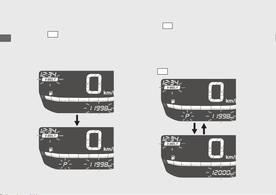
#
Resetting V-BELT indicator
a
Pressing
SET
switch causes the V-BELT
indicator, and the running distance until the
V-BELT indicator lights, to flash.
u “P” flashes when the running distance
until V-BELT indicator lights is displayed.
b
Press
SEL
switch to select maintenance
interval.
u “P” turns off when the maintenance
interval is displayed.
u When the running distance until the
V-BELT indicator lights is displayed, the
V-BELT indicator does not reset even if
SET
switch is pressed.
Operation Guide
38
Instruments (Continued)

c
Pressing
SET
switch resets the V-BELT
indicator. When this is reset, the display
changes to normal.
Operation Guide
39
Indicators
Operation Guide
40
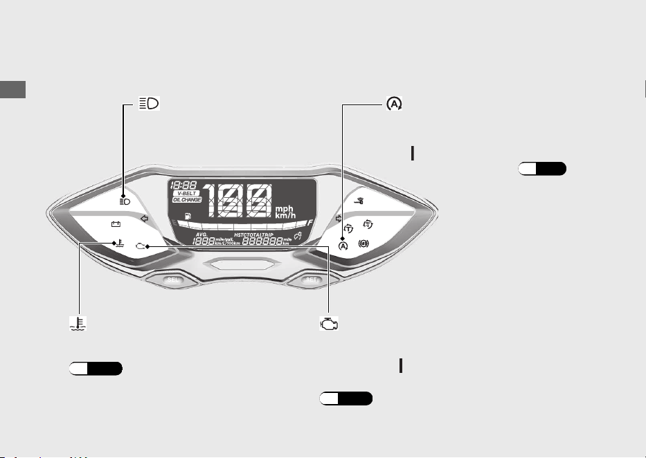
PGM-FI (Programmed Fuel Injection)
malfunction indicator lamp (MIL)
Comes on briefly when the ignition switch is
turned to the (On) position.
If it comes on while engine is running:
(P.127
)
If it comes on while riding:
(P.126
)
High coolant temperature
indicator
If one of these indicators does not come on when it should, have your dealer check
for problems.
Idling Stop system: (P.69)
Comes on briefly when the
ignition switch is turned to
the
(On) position.
Idling Stop indicator
High beam indicator
Operation Guide
41
Continued
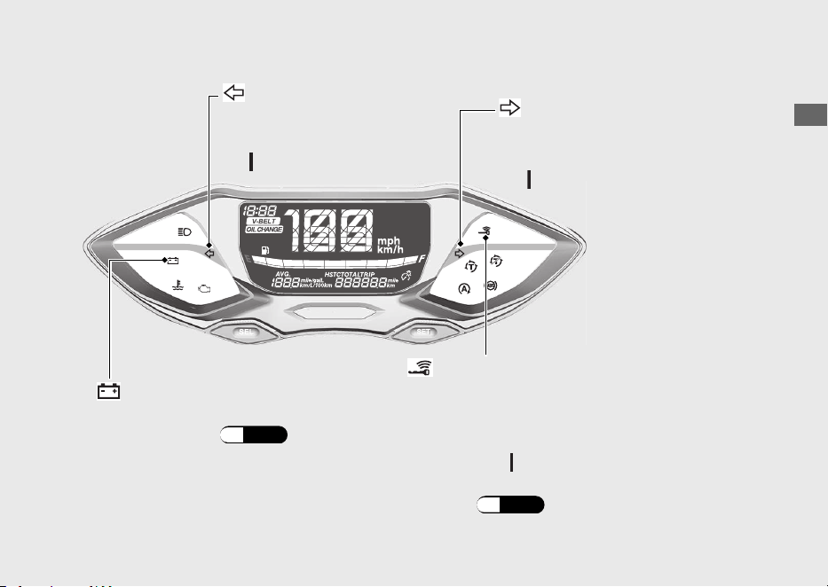
Left turn signal indicator
Right turn signal indicator
Comes on briefly when the
ignition switch is turned to
the
(On) position.
Comes on briefly when the
ignition switch is turned to
the
(On) position.
Goes off when the ignition switch is
turned to the (On) position.
When the Honda SMART Key Indicator
Flashes:
(P.130
)
Comes on when vehicle and Honda SMART
Key verification is complete, and the ignition
switch can be operated.
Honda SMART Key Indicator
Battery Charging Condition
indicator
If it comes on: (P.127)
Operation Guide
42
Indicators (Continued)
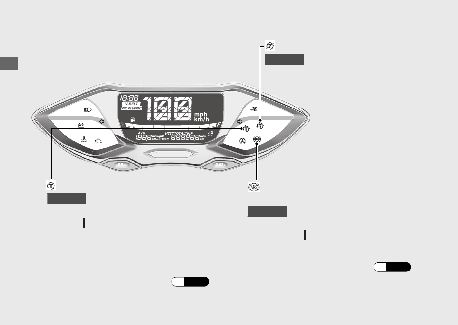
Torque Control indicator
Torque Control OFF indicator
●
Comes on when the ignition switch is turned
to the (On) position.
Comes on when the Torque
Control is turned to off.
Comes on when the ignition switch is
turned to the (On) position.
If it comes on while riding: (P.128)
ABS (Anti-lock Brake System)
indicator
Goes off when your speed reaches
approximately 10 km/h (6 mph).
●
Goes off when your speed reaches
approximately 3 km/h (2 mph) to indicate
Torque Control is ready to work.
●
Blinks when Torque Control is operating.
If it comes on while riding: (P.129)
WW125A
WW125A
WW125A

Operation Guide
43
Switches
Operation Guide
44
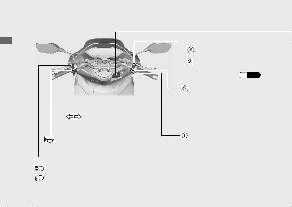
Idling stop switch
Headlight dimmer switch
• : High beam
• : Low beam
Start button
Turn signal switch
u Pressing the switch turns the
turn signal off.
Horn button
• : The Idling Stop system is
on.
• : The Idling Stop system is
off.
Idling Stop system: (P.69)
Hazard switch
The hazard signal is on.
Switchable when the ignition
switch is on.
Operation Guide
45
Continued
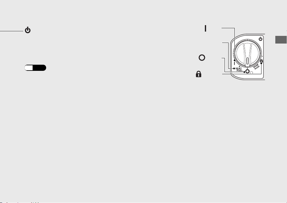
Ignition switch
Switches the electrical system on/off,
locks the steering, and operates the
fuel lid and seat opener switch.
To unlock the ignition switch:
(P.52
)
(On)
Turns electrical system on for starting/riding.
SEAT FUEL
Operates the fuel lid and seat opener switch.
(Lock)
Locks steering.
(Off)
Turns engine off.
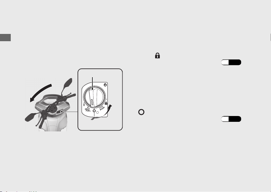
Steering Lock
Lock the steering when parking to help
prevent theft.
A U-shaped wheel lock or similar device is
also recommended.
#
Locking
a
Turn the handlebar all the way to the left or
right.
b
Push the ignition switch down, and turn it to
the (Lock) position.
u To unlock the ignition switch (P.52
)
u Jiggle the handlebar if the lock is difficult
to engage.
c
Lock the ignition switch.
#
Unlocking
Push the ignition switch in, and turn it to the
(Off) position.
u To unlock the ignition switch (P.52)
Operation Guide
46
Switches (Continued)
a
b
Ignition switch
Push
Turn

Honda SMART Key System
The Honda SMART Key system allows you to
operate the ignition switch without inserting
a key into a keyhole.
The system runs a two-way authentication
between the vehicle and the Honda SMART
Key to verify if it is the registered Honda
SMART Key.
The Honda SMART Key system uses low-
intensity radio waves. It may affect medical
equipment such as a cardiac pacemaker.
Operation Guide
47
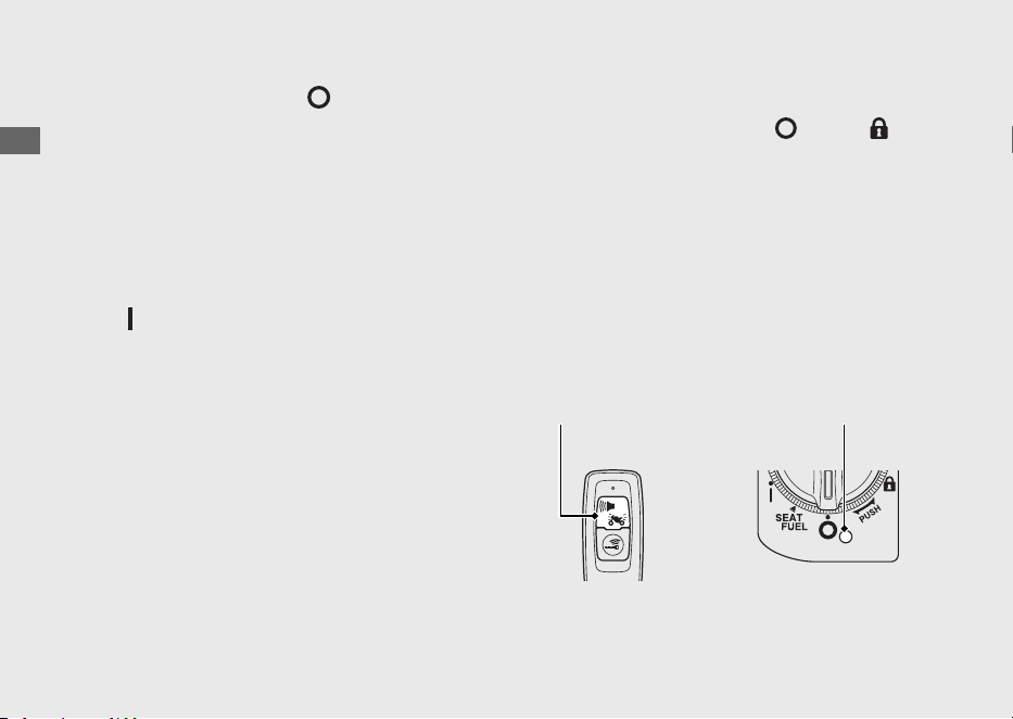
Continued
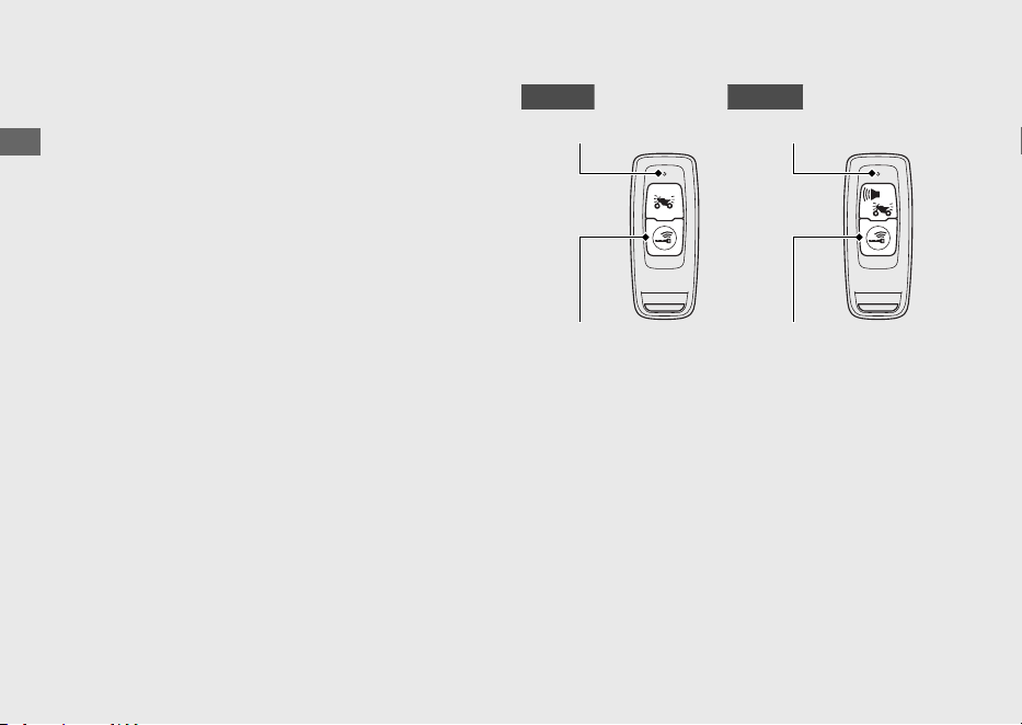
Switching the Honda SMART Key
System
#
To switch the Honda SMART Key
system to activation or deactivation
Press the ON/OFF button until the Honda
SMART Key LED changes colour.
#
To check the Honda SMART Key
system status
Lightly press the ON/OFF button. The Honda
SMART Key LED will show the status.
When the Honda SMART Key LED is:
Green:
(active)
Honda SMART Key system
authentication can be
performed.
Red:
(inactive)
Honda SMART Key system
authentication cannot be
performed.
Operation Guide
48
Honda SMART Key System (Continued)
LED
ON/OFF button
KO typeED type
ON/OFF button
LED
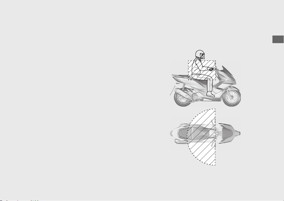
Operating Range
The operating range varies when the ignition
switch is locked or unlocked.
The Honda SMART Key system uses low-
intensity radio waves. Therefore, the
operating range may be wider or narrower,
or the Honda SMART Key system may not
work properly in the following situations:
●
When the Honda SMART Key battery is
depleted.
● When there are facilities nearby that
generate strong radio waves or noise,
such as TV towers, power stations, radio
stations, or airports.
●
When you carry the Honda SMART Key
with a laptop or wireless communication
device such as a radio or mobile phone.
●
When the Honda SMART Key comes into
contact with or is covered by metal
objects.
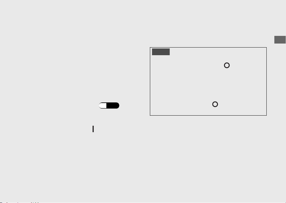
#
When the ignition switch is unlocked:
The system can be operated within the
shaded area shown in the illustration.
Operation Guide
49
Continued
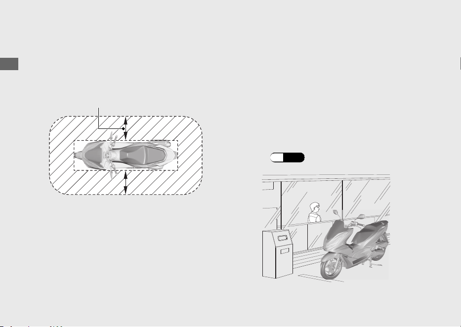
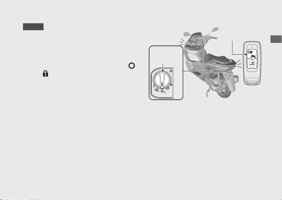
#
When the ignition switch is locked:
The system can be operated within the
shaded area shown in the illustration.
Anyone can unlock the ignition switch and
start the engine if your Honda SMART Key is
within operating range of your vehicle, even
if you are on the other side of a wall or
window. If you are away from your vehicle
but your Honda SMART Key is still within
operating range, deactivate the Honda
SMART Key system.
To switching the Honda SMART Key
system
(P.48)
Operation Guide
50
Honda SMART Key System (Continued)
About 2 m (6.6 ft)

Anyone in possession of the Honda SMART
Key can perform the following operations if
the Honda SMART Key is within operating
range:
● Starting the engine
● Unlocking the ignition switch
● Releasing the seat lock
● Opening the fuel lid
● Unlocking the steering lock
You should always keep the Honda SMART
Key on your person after you get on and off
the vehicle or while riding.
Do not store the Honda SMART Key in any
compartment.
If the ignition switch is in the (On) position,
the vehicle can be operated even by a
person who does not have a verified Honda
SMART Key.
Whenever you leave your vehicle, lock the
steering and lock the ignition switch.
(P.53)
Make sure the ignition switch ring goes off
and all turn signals flash once at this time.
Operation Guide
51
Continued
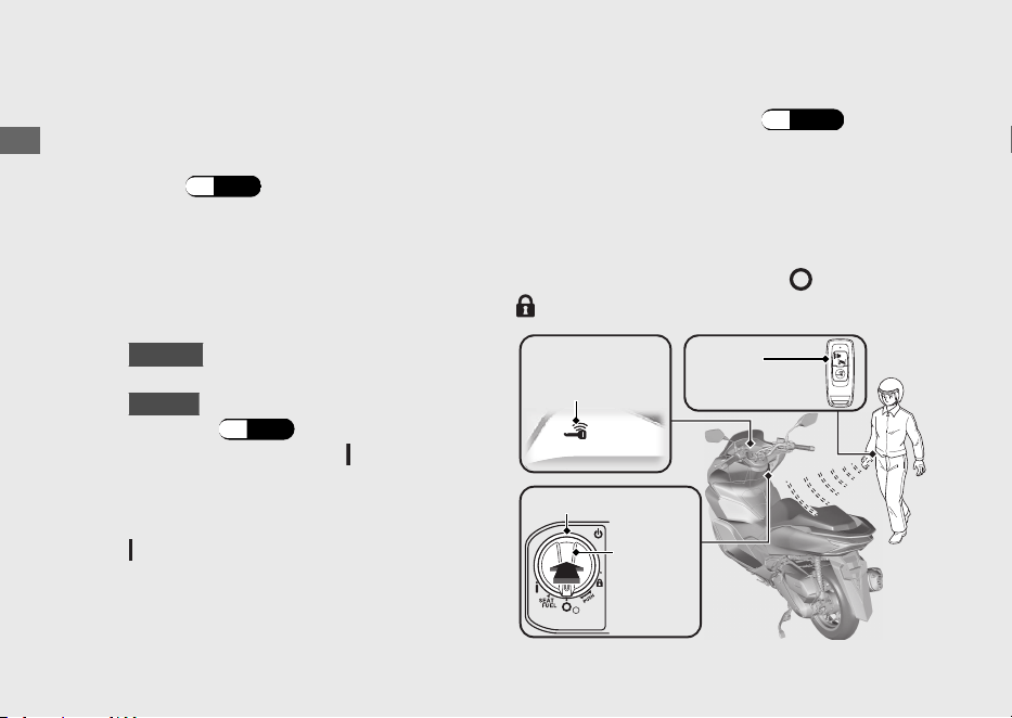
Switching the ignition switch
#
To Unlock the Ignition Switch
a
Make sure that the Honda SMART Key is
activated.
(P.48)
b
To authenticate the Honda SMART Key
system, push the ignition switch.
u
When properly authenticated and the
ignition switch is unlocked, the Honda
SMART Key indicator and ignition switch
ring come on.
KO type
The buzzer also rings 2 times
at this time.
u
KO type
The buzzer sound can be
cancelled. (P.54
)
c
Turn the ignition switch to the (On) position
while the Honda SMART Key indicator comes
on.
u
If you do not turn the ignition switch to the
(On) position within 20 seconds after
pushing in the ignition switch in, the Honda
SMART Key indicator and ignition switch
ring will go off, the turn signals flash 1 time,
and then the ignition switch will be locked.
When the Honda SMART Key system
does not work properly
(P.135)
If someone without the Honda SMART Key
tries to turn the ignition switch, the ignition
switch rotates freely. If you notice the ignition
switch is in a different position, turn the
ignition switch to the original (
(Off) or
(Lock)) position.
Operation Guide
52
Honda SMART Key System (Continued)
Honda
SMART Key
Honda
SMART Key
indicator
Ignition switch ring
Ignition
switch
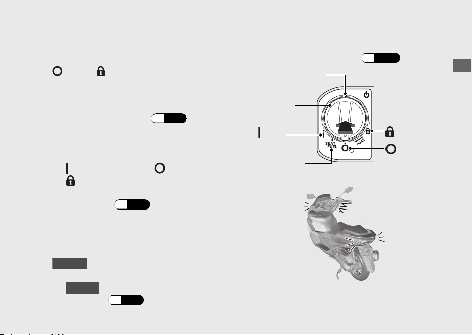
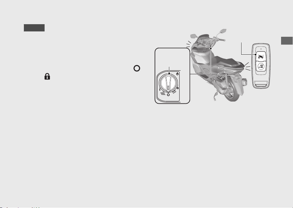
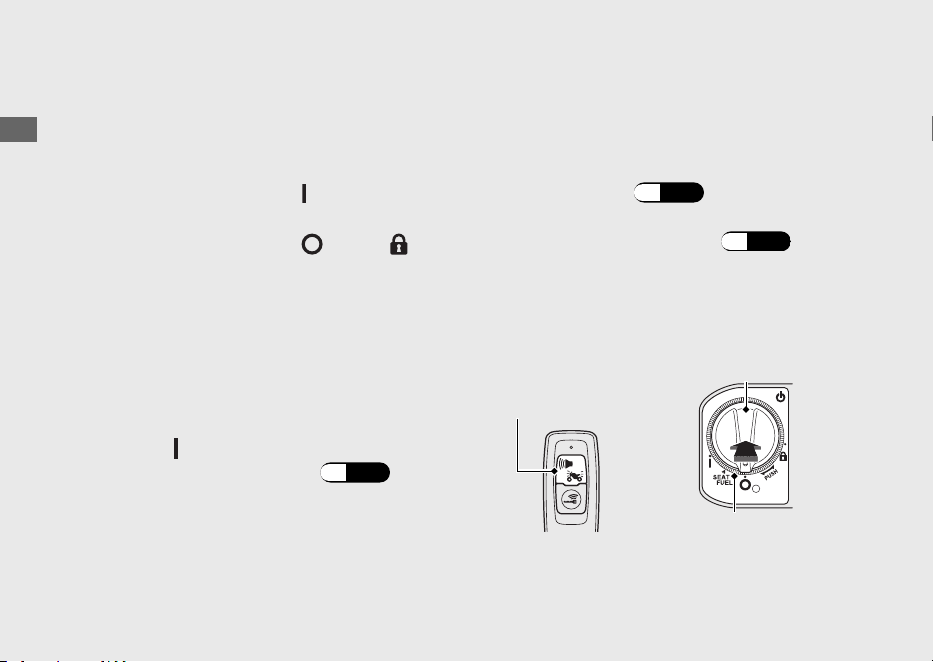
#
To Lock the Ignition Switch
a
Turn the ignition switch to the SEAT FUEL,
(Off) or (Lock) position.
b
Lock the ignition switch by doing one of the
following:
● Leave the operating range with the
Honda SMART Key. (P.49)
●
Push the ignition switch.
●
Wait for approximately 20 seconds
after turning the ignition switch from
(On) to SEAT FUEL, (Off) or
(Lock) position.
● Switch the Honda SMART Key system
to inactive. (P.48
)
c
Make sure that the Honda SMART Key
indicator and ignition switch ring go off and
the turn signals flash once. This indicates
that the ignition switch is locked.
KO type
The buzzer also rings 1 time at
this time.
u
KO type
The buzzer sound can be
cancelled. (P.54)
When the Honda SMART Key system
does not work properly (P.135)
Operation Guide
53
Continued
Ignition switch
ring
Ignition
switch
(On)
SEAT FUEL
(Lock)
(Off)

Always make sure the ignition switch position
is in the (Off) or (Lock) position when
you leave your vehicle.
When the ignition switch is locked in the
SEAT FUEL position, the ignition switch can
be turned
(Off) position only once.
When the ignition switch is locked in the
(Off) position, the steering cannot be
locked. To lock the steering, unlock the
ignition switch.
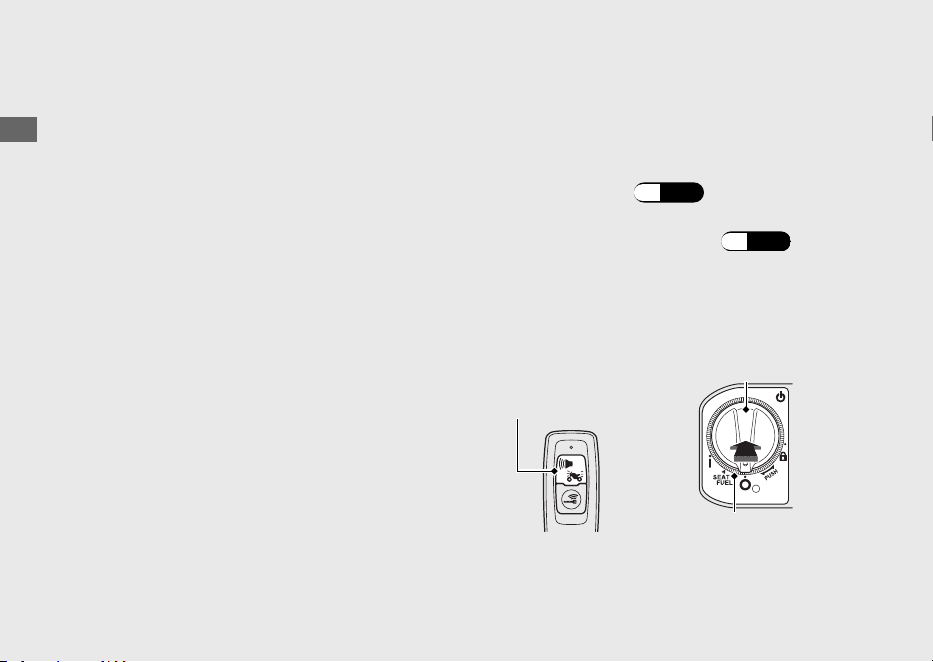
#
Switch the Buzzer Sound When the
Ignition Switch is Locked/Unlocked
KO type
Enable
a
Deactivate the Honda SMART Key system.
(P.48
)
b
Lightly press the ON/OFF button. The red
Honda SMART Key LED comes on.
c
While the red LED is on, press the answer
back/alarm button.
u
The red LED starts blinking when the
buzzer sound is properly enabled.
Disable
a
Deactivate the Honda SMART Key system.
(P.48)
b
Lightly press the ON/OFF button. The red
Honda SMART Key LED blinks.
c
While the red LED is blinking, press the
answer back/alarm button.
u
The red LED stops blinking but stays on
when the buzzer sound is properly
disabled.
Operation Guide
54
Honda SMART Key System (Continued)
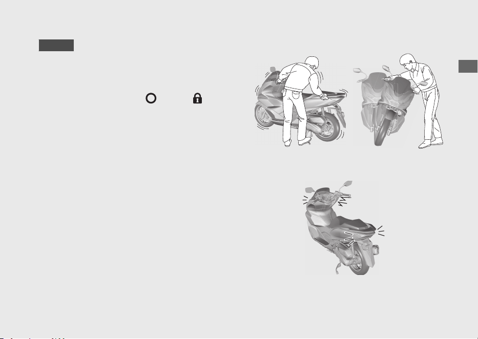
Anti-theft Alarm System
KO type
The anti-theft alarm system is a device to
reduce the likelihood of theft. When the
sensor detects vibration or movement with
the ignition switch in the
(Off) or (Lock)
position and the system is set, the alarm is
activated.
The buzzer rings and the turn signals blink
for about 10 seconds when the anti-theft
alarm system detects vibration caused by
contact or movement.
The buzzer rings and the turn signals blink
for about 60 seconds when the anti-theft
alarm system detects a substantial change in
the vehicle posture. After the buzzer rings for
60 seconds, the anti-theft alarm system will
be reset in that posture.
Operation Guide
55
Continued
If the ignition switch is left (Off) for more
than 10 days, the anti-theft alarm system will
no longer operate. When the system is active
and the vehicle receives a signal from
pressing the answer back/alarm button,
system activation will be extended for 10
days.
To reset the system, turn the ignition switch
to the
(On) position once.
The anti-theft alarm system uses low-
intensity radio waves. It may affect medical
equipment such as a cardiac pacemaker.
When the battery in the vehicle is weak, the
anti-theft alarm system may not function.
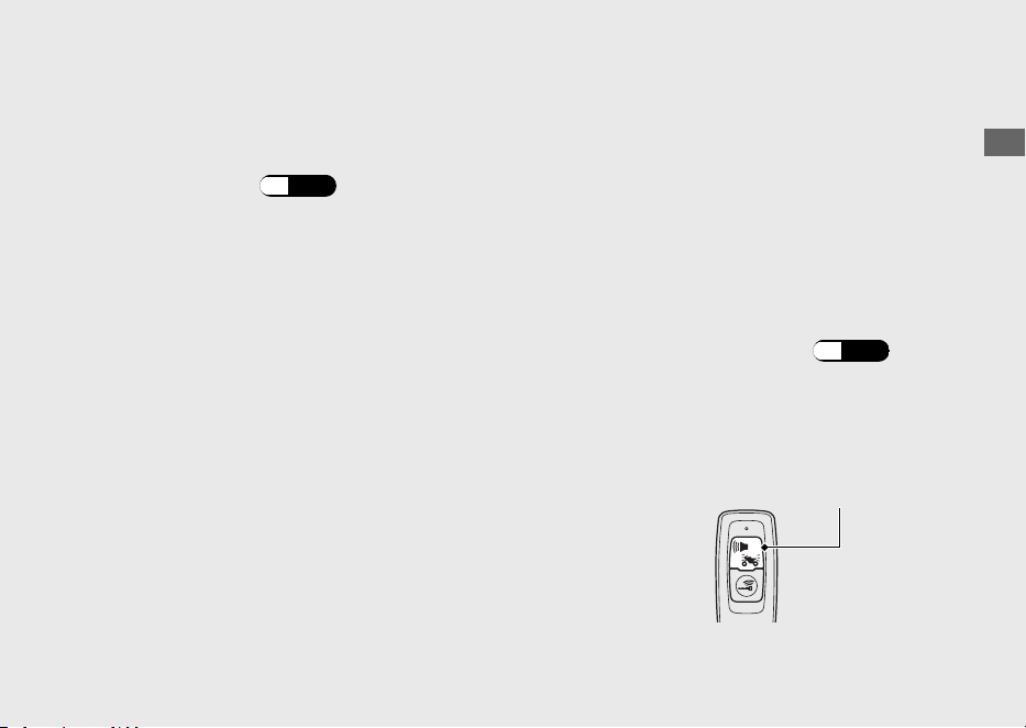
#
Setting the Anti-theft Alarm System
a
Turn the ignition switch to (Off) or
(Lock) position.
b
Press the answer back/alarm button. Within
a second, the turn signal light blinks and the
buzzer rings 1 time. After 2.5 seconds, the
buzzer rings 1 time. The anti-theft alarm
system is activated.
The alarm indicator flashes while the anti-
theft alarm system is activated.
Operation Guide
56
Anti-theft Alarm System (Continued)
Answer back/
alarm button
Alarm indicator
#
Cancelling the Anti-theft Alarm
System
To cancel the anti-theft alarm system, unlock
the ignition switch. (P.52)
When the ignition switch is unlocked, the
buzzer rings 2 times and the alarm indicator
goes off.
#
Stopping the Anti-theft Alarm
Activation
To stop the anti-theft alarm activation, do
one of the following:
● Press the answer back/alarm button on
the Honda SMART Key.
u After stopping the anti-theft alarm
activation, the anti-theft alarm system
will be reset.
● Unlock the ignition switch. (P.52)
u
After stopping the anti-theft alarm
activation, the anti-theft alarm system
will be cancelled.
Operation Guide
57
Continued
Answer back/
alarm button
#
Adjusting the Sensitivity of Anti-theft
Alarm System
You can select from 3 sensitivity levels for the
anti-theft alarm system.
a
Make sure that the Honda SMART Key
system is active. (P.48)
b
Push the ignition switch to authenticate the
Honda SMART Key system. (P.52)
c
Press and hold the ignition switch for more
than 4 seconds.
u The Honda SMART Key indicator and
ignition switch ring flash.
d
Press the ignition switch 1 time while the
Honda SMART Key indicator and ignition
switch ring are flashing.
u The Honda SMART Key indicator and
ignition switch ring come on, and a
buzzer sounds.
e
Repeat the following 3 times:
Press the answer back/alarm button on
the Honda SMART Key 4 times and the
ignition switch 1 time.
Operation Guide
58
Anti-theft Alarm System (Continued)
Answer back/
alarm button
Ignition switch
Ignition switch ring

u When the ignition switch is pressed, the
Honda SMART Key indicator and ignition
switch ring go off, and the buzzer
sounds. When they light again, do the
next input.
u When the answer back/alarm button is
pressed, the Honda SMART Key LED
comes on. Make sure the LED goes off
before pressing the button again.
u
When the answer back/alarm button or
ignition switch is not pressed for 1
minute, the Honda SMART Key indicator
and ignition switch ring flash 3 times,
and then the buzzer sounds and the
mode is cancelled. Return to c and do
the procedure again.
u
If you press the answer back/alarm
button the wrong number of times
before you repeat the procedure 3
times, then repeat the procedure 3 times
again.
f
Press the answer back/alarm button to
select from 3 sensitivity levels.
3 alarm rings: high sensitivity
2 alarm rings: medium sensitivity
1 alarm ring: low sensitivity
The Honda SMART Key indicator and
ignition switch ring come on while setting.
g
Press and hold the ignition switch for more
than 2 seconds. The sensitivity level is set.
u The Honda SMART Key indicator and
ignition switch ring turn off, and a buzzer
sounds once.
u When the answer back/alarm button is
not pressed for 10 seconds, the Honda
SMART Key indicator and ignition switch
ring flash 3 times, and then the buzzer
sounds, and the sensitivity level is set.
Operation Guide
59
Continued

#
If the Anti-Theft Alarm System Does
Not Operate Properly
If any of the following situations arise, the
battery ((P.103) ) in the vehicle may be
discharged or there is a system problem.
Remove the battery and see your dealer.
● The alarm does not ring.
● The alarm rings but fades out.
● The alarm system does not stop.
Operation Guide
60
Anti-theft Alarm System (Continued)
Answer Back System
ED type
The answer back system is a device to find
the location of your vehicle.
When the immobilizer is active and you press
the answer back button on the Honda
SMART Key with the ignition switch in the
(Off) or (Lock) position, the turn signals
light, and the ignition switch ring lights,
informing you of your vehicle's location. The
ignition switch ring will light for about 1
minute.
The answer back system uses low-intensity
radio waves. It may affect medical equipment
such as a cardiac pacemaker.
Operation Guide
61
Continued
Ignition
switch ring
Answer back
button

#
Operation
Press the answer back button on the Honda
SMART Key.
u The answer back system will not function
when the ignition switch is (On) position.
If the ignition switch is left in the (Off) or
(Lock) position for more than 10 days, the
answer back system will no longer operate.
When the system is active and the vehicle
receives a signal from pressing the answer back
button, system activation will be extended for
10 days.
To reset the system, turn the the ignition
switch to the
(On) position once.
u To unlock the ignition switch (P.52)
When the battery in the vehicle is weak, the
answer back system may not function.
Operation Guide
62
Answer Back System (Continued)
KO type
The answer back system is a device to find
the location of your vehicle.
When the immobilizer is active and you press
the answer back/alarm button on the Honda
SMART Key with the ignition switch in the
(Off) or (Lock) position, the turn signals
light, and the ignition switch ring lights,
informing you of your vehicle's location. The
ignition switch ring will light for about 1
minute.
The answer back system uses low-intensity
radio waves. It may affect medical equipment
such as a cardiac pacemaker.
Operation Guide
63
Continued
Ignition
switch ring
Answer back/
alarm button
#
Operation
Press the answer back/alarm button on the
Honda SMART Key.
u The answer back system will not function
when the ignition switch is (On) position.
If the ignition switch is left the (Off) or
(Lock) position for more than 10 days, the
answer back system will no longer operate.
When the system is active and the vehicle
receives a signal from pressing the answer
back/alarm button, system activation will be
extended for 10 days.
To reset the system, turn the the ignition
switch to the
(On) position once.
u To unlock the ignition switch (P.52)
When the battery in the vehicle is weak, the
answer back system may not function.
#
Adjusting the Answer Back Buzzer
Sound Volume Level
You can select 3 buzzer sound volume levels.
a
Make sure that the Honda SMART Key
system is active. (P.48)
b
Push the ignition switch to authenticate the
Honda SMART Key system. (P.52)
c
Press and hold the ignition switch for more
than 4 seconds.
u
The Honda SMART Key indicator and
ignition switch ring flash.
Operation Guide
64
Answer Back System (Continued)
Answer back/
alarm button
Ignition switch
Ignition switch ring

d
Press the ignition switch 1 time while the
Honda SMART Key indicator and ignition
switch ring are flashing.
u The Honda SMART Key indicator and
ignition switch ring come on, and a
buzzer sounds.
e
Repeat the following 3 times:
Press the answer back/alarm button on
the Honda SMART Key 2 times and the
ignition switch 1 time.
u When the ignition switch is pressed, the
Honda SMART Key indicator and ignition
switch ring go off, and the buzzer
sounds. When they light again, do the
next input.
u When the answer back/alarm button is
pressed, the Honda SMART Key LED
comes on. Make sure the LED goes off
before pressing the button again.
u When the answer back/alarm button or
ignition switch is not pressed for 1
minute, the Honda SMART Key indicator
and ignition switch ring flash 3 times,
and then the buzzer sounds and the
mode is cancelled. Return to c and do
the procedure again.
u If you press the answer back/alarm
button the wrong number of times
before you repeat the procedure 3
times, then repeat the procedure 3 times
again.
f
Press the answer back/alarm button to
select from 3 levels for the sound volume.
The Honda SMART Key indicator and
ignition switch ring come on while setting.
Operation Guide
65
Continued
g
Press and hold the ignition switch for more
than 2 seconds. The sound volume level is
set.
u The Honda SMART Key indicator and
ignition switch ring turn off, and a buzzer
sounds once.
u
When the answer back/alarm button is
not pressed for 10 seconds, the Honda
SMART Key indicator and ignition switch
ring flash 3 times, and then the buzzer
sounds, and the sound volume level is
set.
#
Changing the Answer Back Buzzer
Sound Pattern
You can select 3 buzzer sound patterns.
a
Make sure that the Honda SMART Key
system is active. (P.48)
b
Push the ignition switch to authenticate the
Honda SMART Key system. (P.52)
c
Press and hold the ignition switch for more
than 4 seconds.
u
The Honda SMART Key indicator and
ignition switch ring flash.
Operation Guide
66
Answer Back System (Continued)
Answer back/
alarm button
Ignition switch
Ignition switch ring

d
Press the ignition switch 1 time while the
Honda SMART Key indicator and ignition
switch ring are flashing.
u The Honda SMART Key indicator and
ignition switch ring come on, and a
buzzer sounds.
e
Repeat the following 3 times:
Press the answer back/alarm button on
the Honda SMART Key 3 times and the
ignition switch 1 time.
u When the ignition switch is pressed, the
Honda SMART Key indicator and ignition
switch ring go off, and the buzzer
sounds. When they light again, do the
next input.
u When the answer back/alarm button is
pressed, the Honda SMART Key LED
comes on. Make sure the LED goes off
before pressing the button again.
u When the answer back/alarm button or
ignition switch is not pressed for 1
minute, the Honda SMART Key indicator
and ignition switch ring flash 3 times,
and then the buzzer sounds and the
mode is cancelled. Return to c and do
the procedure again.
u If you press the answer back/alarm
button the wrong number of times
before you repeat the procedure 3
times, then repeat the procedure 3 times
again.
f
Press the answer back/alarm button to
select from 3 buzzer sound patterns. The
Honda SMART Key indicator and ignition
switch ring come on while setting.
Operation Guide
67
Continued

g
Press and hold the ignition switch for more
than 2 seconds. The sound pattern is set.
u The Honda SMART Key indicator and
ignition switch ring turn off, and a buzzer
sounds once.
u When the answer back/alarm button is
not pressed for 10 seconds, the Honda
SMART Key indicator and ignition switch
ring flash 3 times, and then the buzzer
sounds, and the sound pattern is set.
#
Temporary Silence Mode
Temporary silence mode is the immediate
way to turn off the answer back system
buzzer sound.
Enable:
Press and hold the answer back/alarm button
for about 2 seconds, the Honda SMART Key
LED changes to red.
Disable:
Re-press and hold the answer back/alarm
button for about 2 seconds, the Honda
SMART Key LED changes to green.
Operation Guide
68
Answer Back System (Continued)
Idling Stop System
Idling Stop system is designed to help reduce
the fuel consumption and noise, by idling
stop while making a stop such as waiting at
an intersection.
#
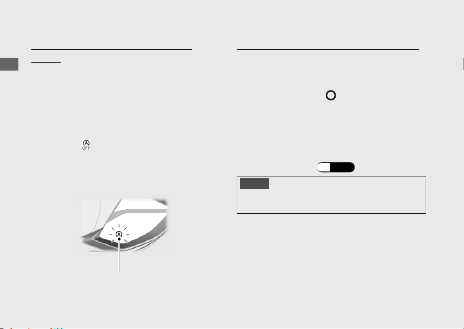
Switching the Idling Stop System On
or Off
Switches the Idling Stop system on or off
using the Idling Stop switch.
●
ON: (Idling Stop)
u
Idling Stop indicator comes on when the
Idling Stop system becomes ready to
stop the engine while riding. Idling Stop
indicator flashes when the engine is
stopped by the Idling Stop system.
● OFF: (Idling)
u
Idling Stop indicator does not come on
when the Idling Stop system is off.
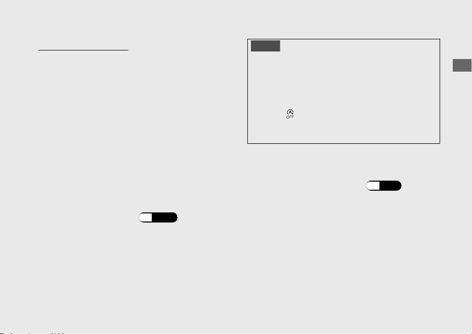
Activation of the Idling Stop System
The Idling Stop system becomes ready to
stop the engine and Idling Stop indicator
comes on when the following requirements
are satisfied with the Idling Stop switch in the
(Idling Stop) position:
● side stand is up
●
start the engine by pressing the start button
●
warm up the engine enough
●
ride the vehicle at speeds over 10 km/h (6
mph)
#
Idling Stop Indicator Does Not Come On:
(P.132
)
Operation Guide
69
Continued
Idling Stop switch
Idling Stop
indicator
Stopping the engine by the Idling Stop
System
The engine stops and Idling Stop indicator
changes to flash after you close the throttle
completely and stop the vehicle while the
Idling Stop indicator is on.
u While the engine is stopped by the Idling
Stop system, if you press the Idling Stop
switch to (Idling), the Idling Stop system
will be cancelled. The engine will not restart
even when you open the throttle.
Safety Precaution for the Idling Stop System
Do not go away from the vehicle while the
Idling Stop indicator is flashing. When you go
away from the vehicle, always turn the
ignition switch to the
(Off) position.
u The engine may start unexpectedly if the
throttle is opened.
#
Engine is Not Stopped by the Idling
Stop System While the Idling Stop
Indicator is On: (P.133)
NOTICE
Stopping by the Idling Stop system for a long
time may cause battery discharge.
Operation Guide
70
Idling Stop System (Continued)
Idling Stop indicator
Restarting the Engine
Check that the Idling Stop indicator is
flashing, and then open the throttle.
u If it is not flashing, you can't restart the
engine with the Idling Stop system, even if
you open the throttle.
u While the engine is stopped by the Idling
Stop system, if you operate the side stand,
the flashing Idling Stop indicator turns off or
stops flashing and stays on, then the engine
will not restart even when you open the
throttle.
#
Engine Does Not Start Even If the
Throttle is Opened: (P.134)
NOTICE
Headlight stays on after the engine is stopped by
the Idling Stop system. The battery may
discharge and you may not be able to restart
engine.
When the battery is weak, switch the Idling Stop
switch to (Idling) and do not to use the Idling
Stop system. See your dealer to check the
battery.
See your dealer for checking the battery as
specified in the maintenance schedule.
#
Maintenance Schedule: (P.89)
Operation Guide
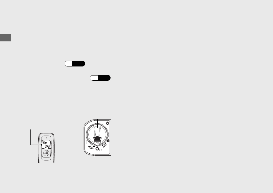
71
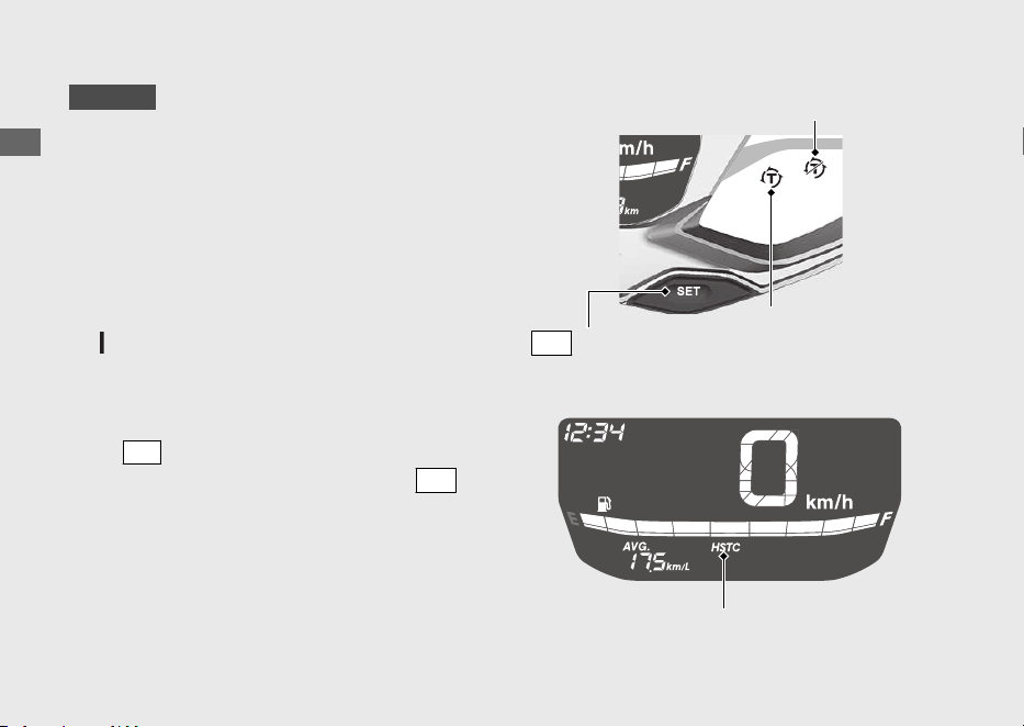
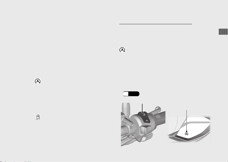
Honda selectable torque control
WW125A
Torque Control (engine power control) can
be turned on/off.
u Stop the vehicle first, turn the Torque
Control off or on.
u The Torque Control cannot be turned off
when the system is activated (Torque
Control indicator blinking).
u Each time the ignition switch is turned to the
(On) position, the Torque Control will
automatically be set to on.
Torque Control on and off
Press
SEL
switch to display the Torque
Control [HSTC]. Pressing and holding
SET
switch while Torque Control [HSTC] is
displayed switches between on and off.
Operation Guide
72
Torque Control OFF indicator
Torque Control
indicator
SET
switch
Torque Control [HSTC]
Starting the Engine
Start your engine using the following procedure,
regardless of whether the engine is cold or warm.
This vehicle is equipped with a side stand
ignition cut-off system.
u If the side stand is down, the engine cannot
be started.
u
If you lower the side stand with the engine
running, it will automatically shut off.
This vehicle is equipped with a Honda SMART
Key system. Always keep Honda SMART Key on
you when you ride the vehicle. (P.49
)
If the engine of this vehicle is stopped while
the ignition switch is in the (On) position,
authentication will be disabled after a certain
amount of time or if you leave the
authentication range. Restart the engine by
performing step
c
&
d
under the starting
procedure.
u If the engine of this vehicle is stopped by the
Idling Stop System, authentication will not
be disabled.
NOTICE
•
If the engine does not start within 5 seconds,
turn the ignition switch to the (Off) position
and wait 10 seconds before trying to start the
engine again to recover battery voltage.
•
Extended fast idling and revving the engine can
damage the engine, and the exhaust system.
•
If the vehicle is over-turned, you must first turn
the ignition switch to the (Off) position and
then inspect the vehicle carefully.
Operation Guide
73
Continued
a
Place the vehicle on its centre stand.
b
Turn the ignition switch to the (On)
position.
u To unlock the ignition switch. (P.52)
c
Squeeze the rear brake lever.
u The starter motor will only work when
the rear brake lever is squeezed and the
side stand is up.
d
Press the start button with the throttle
completely closed. Release the start button
as soon as the engine starts.
Operation Guide
74
Starting the Engine (Continued)
b
dc
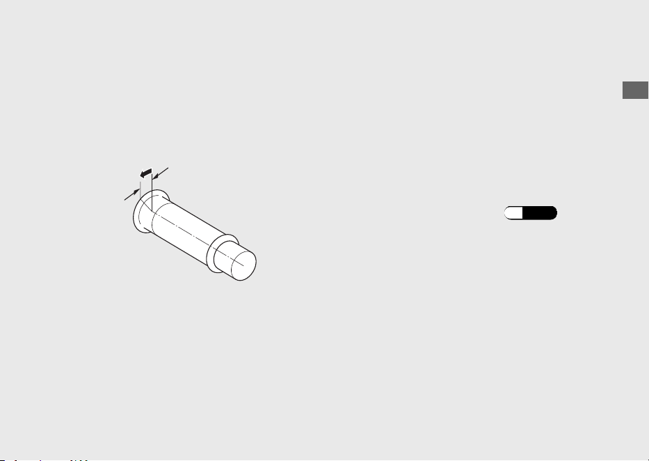
If you cannot start the engine:
a
Place the vehicle on its centre stand and
squeeze the rear brake lever.
b
With the throttle slightly open (about 3 mm,
without freeplay), press the start button.
If the engine does not start:
a
Open the throttle fully and press the start
button for 5 seconds.
b
Repeat the normal starting procedure.
c
If the engine starts, open the throttle slightly
if idling is unstable.
d
If the engine does not start, wait 10 seconds
before trying steps a & b again.
#
If Engine Will Not Start (P.125)
Operation Guide
75
About 3 mm, without freeplay
Riding
Starting the Vehicle
a
Push the vehicle forward off the center
stand.
u Squeeze the rear brake lever.
u Keep throttle closed.
Make sure the side stand and centre stand
are up.
b
Get on the vehicle.
u Mount the vehicle from the left side,
keeping at least one foot on the ground.
c
Release the brake lever.
d
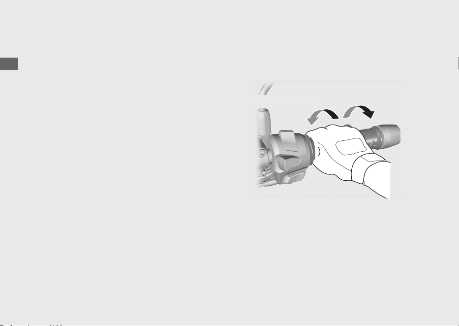
Acceleration and deceleration
To accelerate: Open the throttle slowly.
To decelerate: Close the throttle.
Operation Guide
76
Close (Decelerate)
Open (Accelerate)
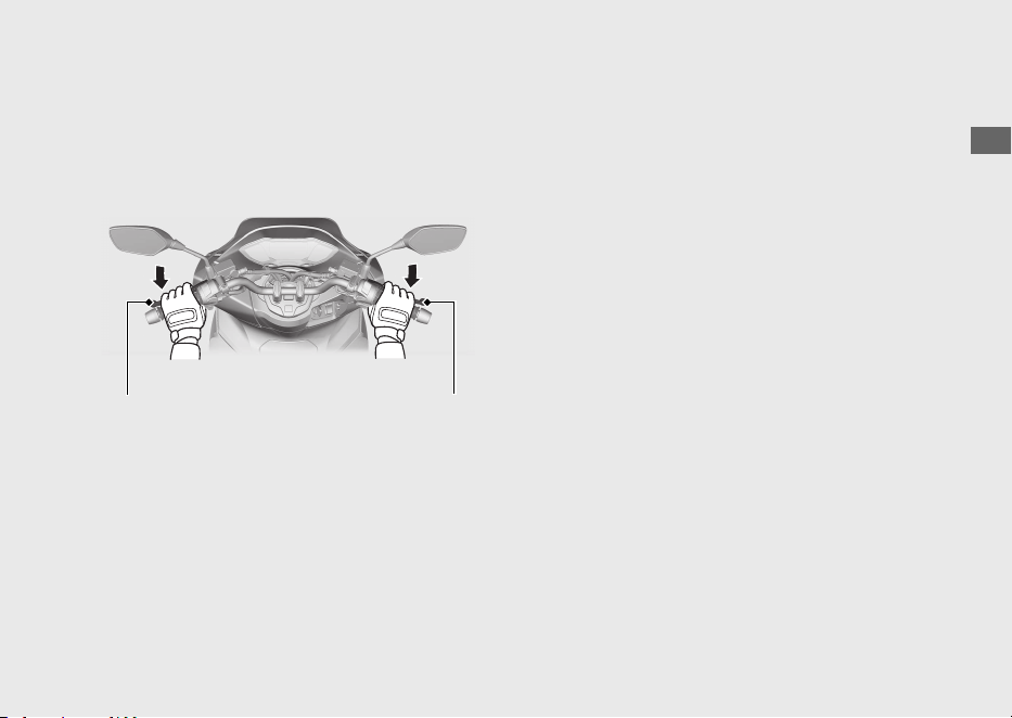
Braking
Close the throttle and apply the front and
rear brake levers together.
Operation Guide
77
Rear brake lever Front brake lever
Refuelling
Fuel type: Unleaded petrol only
Fuel octane number: Your vehicle is
designed to use Research Octane Number
(RON) 91 or higher.
Tank capacity: 8.1 L (2.14 US gal, 1.78 Imp
gal)
#
Refuelling and Fuel Guidelines (P.14)
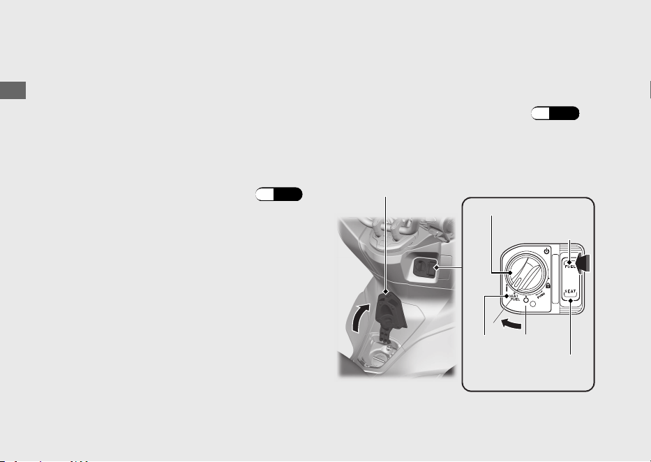
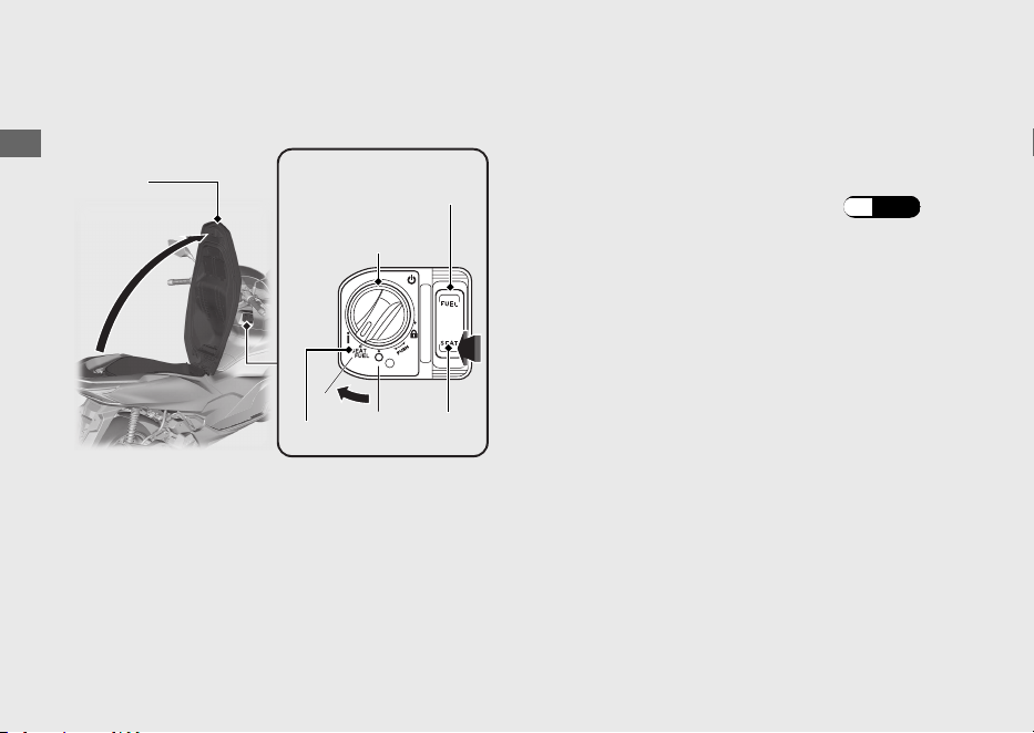
Opening the Fuel Fill Cap
a
Turn the ignition switch to the position of
SEAT FUEL.
u To unlock the ignition switch (P.52)
b
Push the FUEL side of the fuel lid and seat
opener switch.
u The fuel lid opens.
Operation Guide
78
Ignition switch
Fuel lid
FUEL
SEAT FUEL
Fuel lid and seat
opener switch
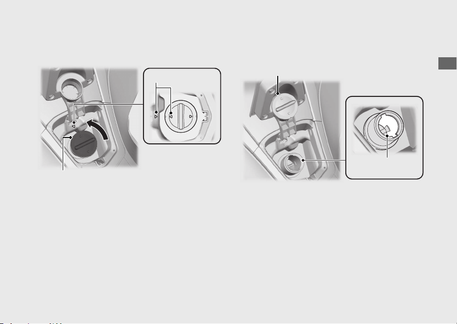
c
Turn the fuel fill cap counterclockwise and
remove the fuel fill cap.
d
Put the removed fuel fill cap on the fuel fill
cap resting place.
Do not fill with fuel above the lower edge of
the filler neck.
Operation Guide
79
Continued
Arrow marks
Fuel fill cap
Fuel fill cap resting place
Lower edge of
filler neck
Closing the Fuel Fill Cap
a
Install and tighten the fuel fill cap firmly by
turning it clockwise.
u Make sure that the arrow marks on the
fuel fill cap and fuel tank are aligned.
b
Close the fuel lid until it locks.
u Make sure that the fuel lid is closed
securely.
3WARNING
Petrol is highly flammable and
explosive. You can be burned or
seriously injured when handling fuel.
• Stop the engine, and keep heat,
sparks, and flame away.
• Handle fuel only outdoors.
• Wipe up spills immediately.
Operation Guide
80
Refuelling (Continued)
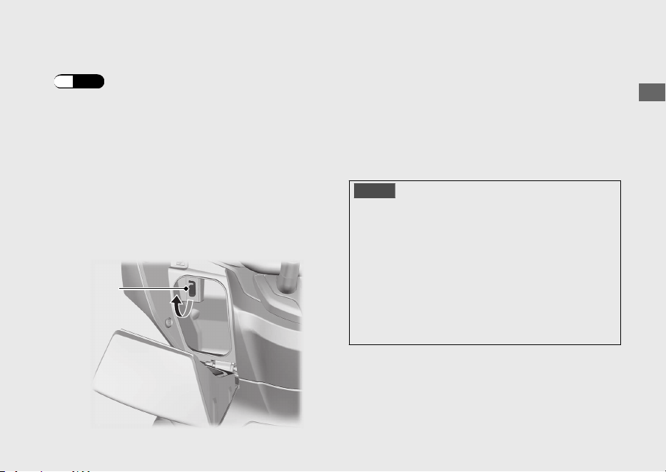
USB Socket
The USB socket is located in the front box.
(P.85)
Use USB devices at your own risk. In no event
shall Honda be liable for any damage to your
USB device when in use.
Open the cover to access the USB socket.
USB type-C connectors can be used.
Rated capacity is
15 W (5 V, 3.0 A).
u
The USB socket is for charging only.
u To prevent the battery from becoming weak
(or dead), keep the engine running while
drawing current from the USB socket.
u To prevent entry of foreign matter into the
USB socket, be sure to close the cover when
the USB socket is not used.
NOTICE
● Using any heat-generating USB devices or
improperly rated USB devices can damage
the USB socket.
● Do not use the USB socket in wet conditions,
when or while washing or any other wet
conditions as these will damage the USB
socket.
●
Do not allow the USB's harness to become
pinched or trapped.
Operation Guide
81
Cover
Storage Equipment
Seat Seat Open
a
Turn the handlebar pointed straight ahead.
b
Turn the ignition switch to the position of
SEAT FUEL.
u To unlock the ignition switch (P.52)
c
Push the SEAT side of the fuel lid and seat
opener switch.
d
Open the seat.
Seat Close
Close and push down on the rear of the seat
until it locks. Make sure that the seat is locked
securely by pulling it up lightly.
Take care not to lock your key in the
compartment under the seat.
Operation Guide
82
SEAT FUEL
Seat
Fuel lid and seat
opener switch
Ignition switch
SEAT
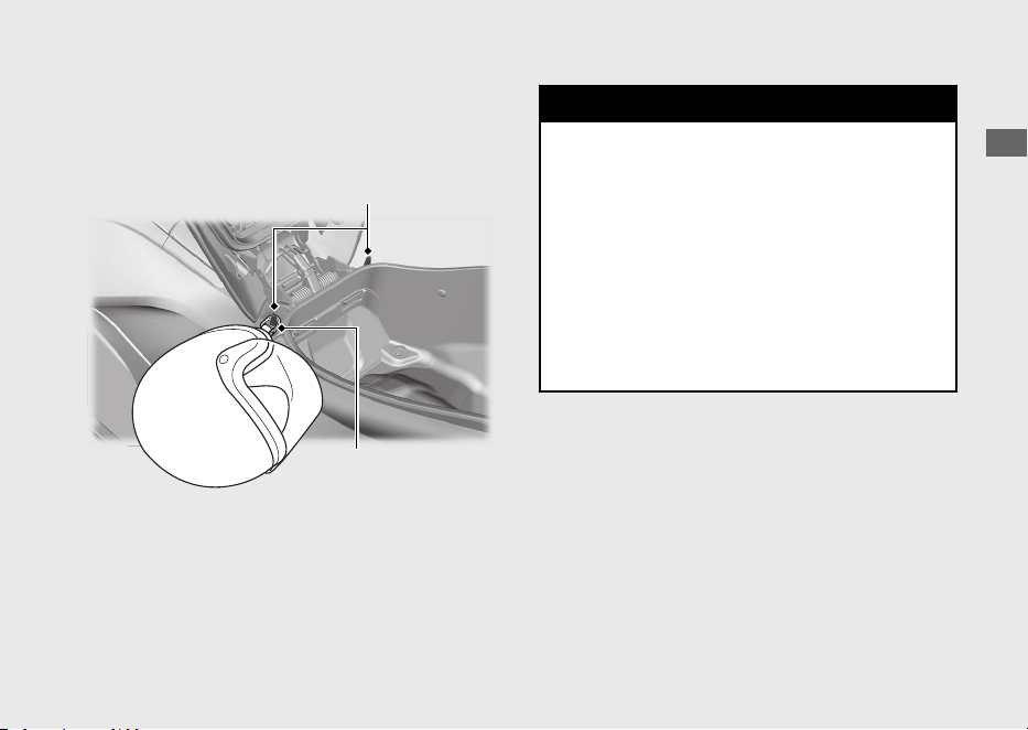
Helmet Holder
The helmet holder is located under the seat.
u Use the helmet holder only when parked.
3WARNING
Riding with a helmet attached to the
holder can interfere with your ability to
safely operate the vehicle and could
lead to a crash in which you can be
seriously hurt or killed.
Use the helmet holder only while
parked. Do not ride with a helmet
secured by the holder.
Operation Guide
83
Continued
Helmet holder
Helmet D-ring
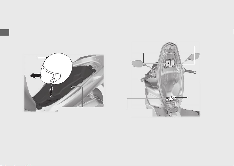
A helmet can be stored in the centre
compartment.
Set in the front of the helmet forward.
u Some helmets may not fit in the
compartment due to their size or design.
Centre compartment
Never exceed the maximum weight limit.
Maximum Weight: 10 kg (22 lb)
u
Do not store any items that are flammable
or susceptible to heat damage.
u
Do not store valuables or fragile articles.
Tool Kit/Document Bag
The tool kit and document bag are located
underside of the seat by the rubber strap.
Operation Guide
84
Storage Equipment (Continued)
Helmet
Centre compartment
Rubber strap
Tool kit
Document bag
Rubber strap
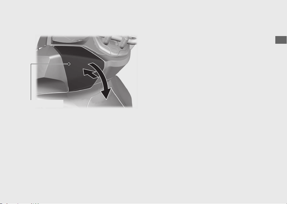
Front Box
#
Open
Push the front box lid, then open the front
box lid.
#
Close
Close the front box lid by pressing the front
box lid.
The maximum allowable load in the front box
shall be no more than
1.0 kg (2.2 lb)
Make sure that the front box lid is closed
securely.
u
Do not store valuables or fragile articles.
Operation Guide
85
Continued
Front box lid
Rear Carrier
Never exceed the maximum weight limit.
Maximum Weight: 5 kg (11 lb)
Operation Guide
86
Storage Equipment (Continued)
Rear carrier

Importance of Maintenance ........................... P. 88
Maintenance Schedule..................................... P. 89
Maintenance Fundamentals ...........................P. 92
Tool..................................................................... P. 102
Removing & Installing Body
Components ...................................................P. 103
Battery.................................................................. P. 103
Battery Cover ..................................................... P. 104
Front Lid ..............................................................P. 105
Engine Oil.......................................................... P. 106
Coolant .............................................................. P. 108
Brakes................................................................. P. 110
Side Stand ......................................................... P. 119
Throttle .............................................................. P. 120
Other Replacement......................................... P. 121
Replacing the Honda SMART Key Battery .. P. 121
Please read “Importance of Maintenance” and “Maintenance Fundamentals” carefully
before attempting any maintenance. Refer to “Specifications” for service data.
Maintenance
Importance of Maintenance
Importance of Maintenance
Keeping your vehicle well-maintained is
absolutely essential to your safety and to
protect your investment, obtain maximum
performance, avoid breakdowns, and reduce air
pollution. Maintenance is the owner's
responsibility. Be sure to inspect your vehicle
before each ride, and perform the periodic
checks specified in the Maintenance Schedule.
2 P. 89
3WARNING
Improperly maintaining your vehicle or
failing to correct a problem before you
ride can cause a crash in which you can
be seriously hurt or killed.
Always follow the inspection and
maintenance recommendations and
schedules in this owner's manual.
Maintenance Safety
Always read the maintenance instructions
before you begin each task, and make sure that
you have the tools, parts, and skills required.
We cannot warn you of every conceivable
hazard that can arise in performing
maintenance. Only you can decide whether or
not you should perform a given task.
Follow these guidelines when performing
maintenance.
●
Stop the engine and turn the ignition switch
to the (Off) position.
●
Place your vehicle on a firm, level surface
using the side stand, centre stand or a
maintenance stand to provide support.
●
Allow the engine, muffler, brakes, and other
high-temperature parts to cool before
servicing as you can get burned.
●
Run the engine only when instructed, and
do so in a well-ventilated area.
Maintenance
88

Maintenance Schedule
The maintenance schedule specifies the
maintenance requirements necessary to ensure
safe, dependable performance, and proper
emission control.
Maintenance work should be performed in
accordance with Honda's standards and
specifications by properly trained and equipped
technicians. Your dealer meets all of these
requirements. Keep an accurate record of
maintenance to help ensure that your vehicle is
properly maintained.
Make sure that whomever performs the
maintenance completes this record.
All scheduled maintenance is considered a
normal owner operating cost and will be
charged to you by your dealer. Retain all
receipts. If you sell the vehicle, these receipts
should be transferred with the vehicle to the
new owner.
Honda recommends that your dealer should
road test your vehicle after each periodic
maintenance is carried out.
Maintenance
89
Continued
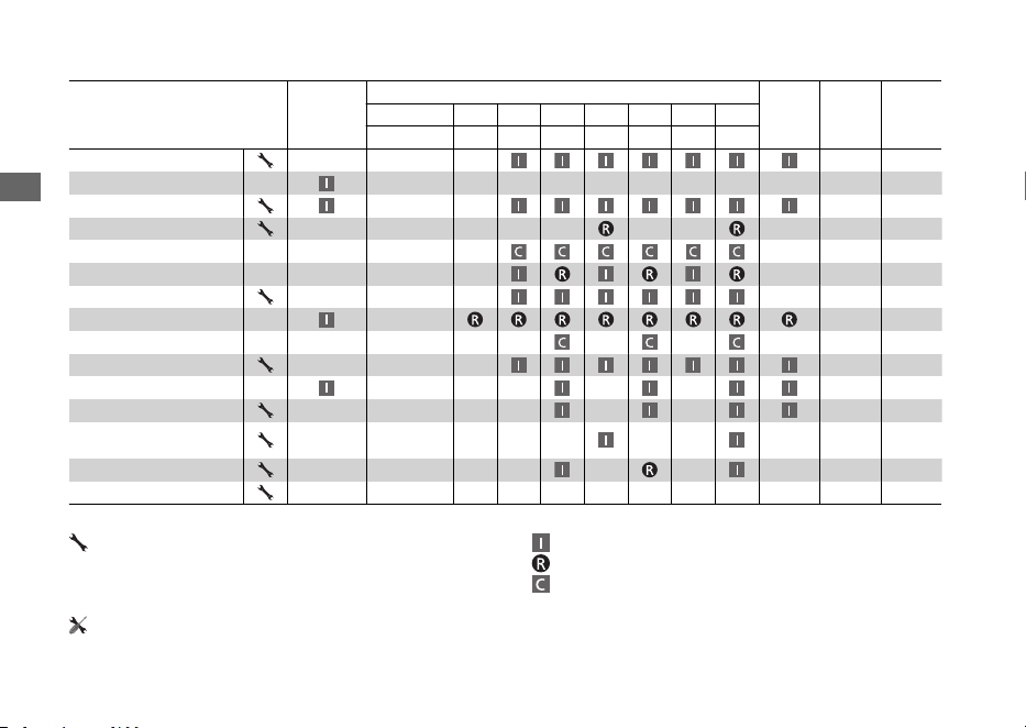
Items
Pre-ride
Check
2 P. 92
Frequency
*1
Annual
Check
Regular
Replace
Refer to
page
× 1,000 km 1 6 12 18 24 30 36
× 1,000 mi 0.6 4 8 12 16 20 24
Fuel Line –
Fuel Level 78
Throttle Operation 120
Air Cleaner
*2
–
Crankcase Breather
*3
–
Spark Plug –
Valve Clearance –
Engine Oil –
Engine Oil Strainer Screen
–
Engine Idle Speed –
Radiator Coolant
*4
3 Years 108
Cooling System –
Evaporative Emission
Control System
–
Drive Belt –
Final Drive Oil
*4
2 Years –
Maintenance Level Maintenance Legend
:
Intermediate. We recommend service by your
dealer, unless you have the necessary tools and are
mechanically skilled.
Procedures are provided in an official Honda Shop Manual.
:
:
:
Inspect (clean, adjust, lubricate, or replace, if necessary)
Replace
Clean
:
Technical. In the interest of safety, have your vehicle
serviced by your dealer.
Maintenance Schedule
Maintenance
90
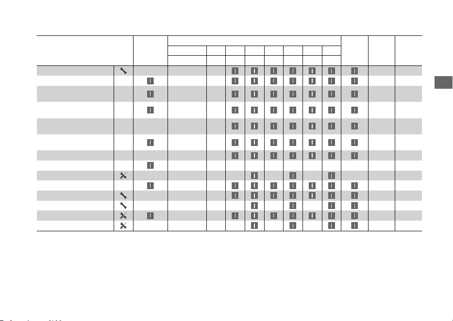
Items
Pre-ride
Check
2 P. 92
Frequency
*1
Annual
Check
Regular
Replace
Refer to
page
× 1,000 km 1 6 12 18 24 30 36
× 1,000 mi 0.6 4 8 12 16 20 24
Battery 103
Brake Fluid
*4
2 Years 110
Brake Pads Wear
(Rear Brake Disk type)
113
Brake Shoes/Pads Wear
(Rear Brake Drum type)
114,
118
Brake System
(Rear Brake Disk type)
92
Brake System
(Rear Brake Drum type)
92
Headlight Aim –
Lights/Horn –
Clutch Shoes Wear –
Side Stand 119
Suspension –
Nuts, Bolts, Fasteners –
Wheels/Tyres 99
Steering Head Bearings –
Notes:
*
1 : At higher odometer reading, repeat at the frequency interval established here.
*
2 : Service more frequently when riding in unusually wet or dusty areas.
*
3 : Service more frequently when riding in rain or at full throttle.
*
4 : Replacement requires mechanical skill.
Maintenance Schedule
Maintenance
91

Maintenance Fundamentals
Pre-ride Inspection
To ensure safety, it is your responsibility to
perform a pre-ride inspection and make sure
that any problem you find is corrected. A pre-
ride inspection is a must, not only for safety, but
because having a breakdown, or even a flat
tyre, can be a major inconvenience.
Check the following items before you get on
your vehicle:
● Fuel level - Fill fuel tank when necessary.
2 P. 79
●
Throttle - Check for smooth opening and
full closing in all steering positions. 2 P. 120
●
Engine oil level - Add engine oil if necessary.
Check for leaks. 2 P. 106
●
Coolant level - Add coolant if required.
Check for leaks. 2 P. 108
● Brakes - Check operation;
WW125A KO type
Front and Rear: check brake fluid level and
pads wear. 2 P. 110, 2 P. 113
WW125
Front: check brake fluid level and pads wear.
2 P. 111, 2 P. 114
Combi Brake: check brake fluid level. 2 P. 111
Rear: check shoes wear and freeplay, adjust
if necessary. 2 P. 115, 2 P. 118
WW125A ED type
Front: check brake fluid level and pads wear.
2 P. 112, 2 P. 114
Rear: check shoes wear and freeplay, adjust
if necessary. 2 P. 115, 2 P. 118
●
Lights and horn - Check that lights,
indicators and horn function properly.
●
Side stand ignition cut-off system - Check
for proper function. 2 P. 119
●
Wheels and tyres - Check condition, air
pressure and adjust if necessary. 2 P. 99
Maintenance
92
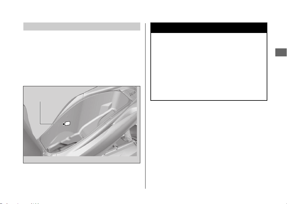
Replacing Parts
Always use Honda Genuine Parts or their
equivalents to ensure reliability and safety.
When ordering coloured components, specify
the model name, colour, and code mentioned
on the colour label.
The colour label is attached to the centre
compartment. 2 P. 84
3WARNING
Installing non-Honda parts may make
your vehicle unsafe and cause a crash in
which you can be seriously hurt or
killed.
Always use Honda Genuine Parts or
equivalents that have been designed
and approved for your vehicle.
Maintenance Fundamentals
Maintenance
93
Colour label
Battery
Your vehicle has a maintenance-free type
battery. You do not have to check the battery
electrolyte level or add distilled water. Clean the
battery terminals if they become dirty or
corroded.
Do not remove the battery cap seals. There is
no need to remove the cap when charging.
NOTICE
Your battery is a maintenance-free type and can
be permanently damaged if the cap strip is
removed.
ED type
This symbol on the battery means
that this product must not be treated
as household waste.
NOTICE
An improperly disposed of battery can be
harmful to the environment and human health.
Always confirm local regulations for proper
battery disposal instruction.
#
What to do in an emergency
If any of the following occur, immediately see
your doctor.
●
Electrolyte splashes into your eyes:
u Wash your eyes repeatedly with cool
water for at least 15 minutes. Using water
under pressure can damage your eyes.
● Electrolyte splashes onto your skin:
u
Remove affected clothing and wash your
skin thoroughly using water.
● Electrolyte splashes into your mouth:
u
Rinse mouth thoroughly with water, and
do not swallow.
Maintenance Fundamentals
Maintenance
94
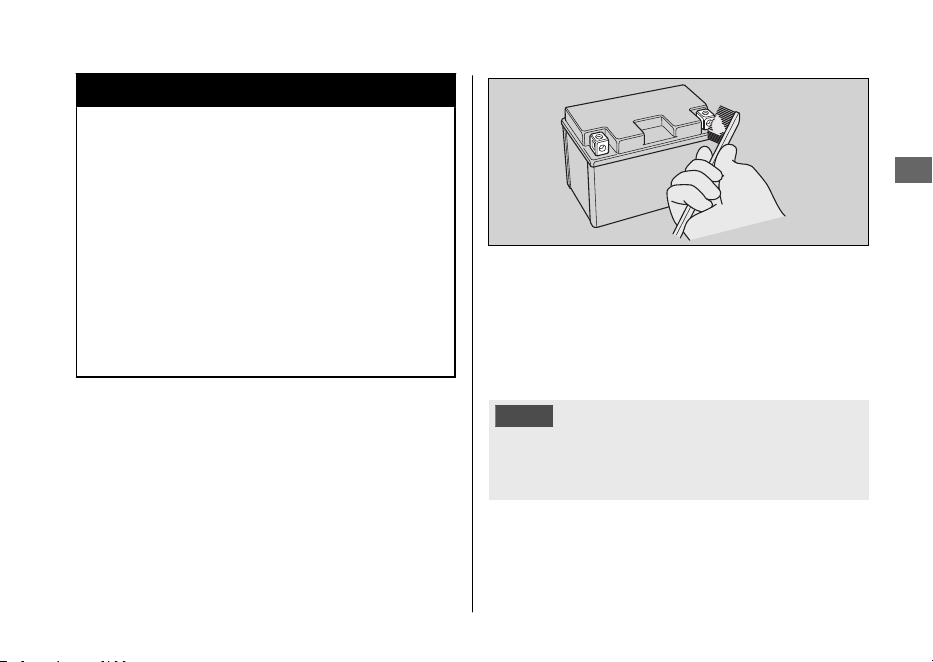
3WARNING
The battery gives off explosive
hydrogen gas during normal operation.
A spark or flame can cause the battery
to explode with enough force to kill or
seriously hurt you.
Wear protective clothing and a face
shield, or have a skilled mechanic do
the battery servicing.
#
Cleaning the Battery Terminals
1.
Remove the battery. 2 P. 103
2.
If the terminals are starting to corrode and
are coated with a white substance, wash
with warm water and wipe clean.
3.
If the terminals are heavily corroded, clean
and polish the terminals with a wire brush or
sandpaper. Wear safety glasses.
4.
After cleaning, reinstall the battery.
The battery has a limited life span. Consult your
dealer about when you should replace the
battery. Always replace the battery with another
maintenance-free battery of the same type.
NOTICE
Installing non-Honda electrical accessories can
overload the electrical system, discharging the
battery and possibly damaging the system.
Maintenance Fundamentals
Maintenance
95
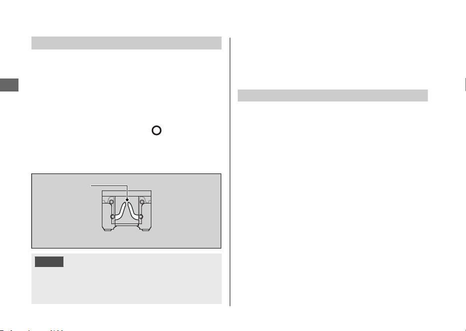
Fuses
Fuses protect the electrical circuits on your
vehicle. If something electrical on your vehicle
stops working, check for and replace any blown
fuses. 2 P. 143
#
Inspecting and Replacing Fuses
Turn the ignition switch to the (Off) position
to remove and inspect fuses. If a fuse is blown,
replace with a fuse of the same rating. For fuse
ratings, see “Specifications.” 2 P. 164
NOTICE
Replacing a fuse with one that has a higher
rating greatly increases the chance of damage to
the electrical system.
If a fuse fails repeatedly, you likely have an
electrical fault. Have your vehicle inspected by
your dealer.
Engine Oil
Engine oil consumption varies and oil quality
deteriorates according to riding conditions and time
elapsed.
Check the engine oil level regularly, and add the
recommended engine oil if necessary. Dirty oil or old oil
should be changed as soon as possible.
#
Selecting the Engine Oil
For recommended engine oil, see
“Specifications.”2 P. 163
If you use non-Honda engine oil, check the label to
make sure that the oil satisfies all of the following
standards:
●
JASO T 903 standard
*1
: MB
●
SAE standard
*2
: 10W-30
●
API classification
*3
: SG or higher
Maintenance Fundamentals
Maintenance
96
Blown fuse
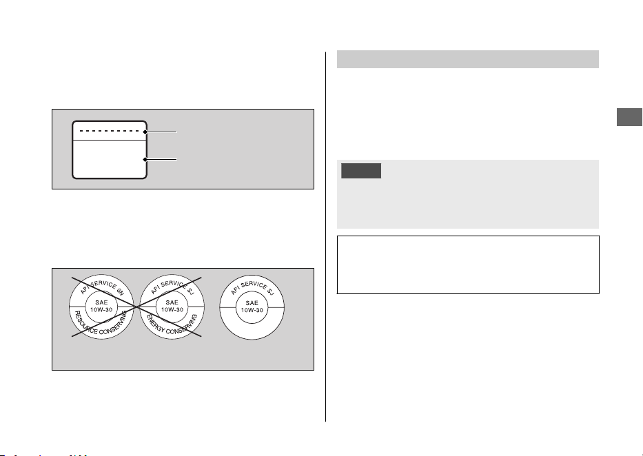
MB
*1.
The JASO T 903 standard is an index for engine oils for 4-
stroke motorcycle engines. There are two classes: MA and
MB. For example, the following label shows the MB
classification.
*2.
The SAE standard grades oils by their viscosity.
*3.
The API classification specifies the quality and performance
rating of engine oils. Use SG or higher oils, excluding oils
marked as “Energy Conserving” or “Resource Conserving”
on the circular API service symbol.
Brake Fluid
Do not add or replace brake fluid, except in an
emergency. Use only fresh brake fluid from a
sealed container. If you do add fluid, have the
brake system serviced by your dealer as soon as
possible.
NOTICE
Brake fluid can damage plastic and painted
surfaces.
Wipe up spills immediately and wash thoroughly.
Recommended brake fluid:
Honda DOT 3 or DOT 4 Brake Fluid or
equivalent
Maintenance Fundamentals
Maintenance
97
Oil code
Oil classification
Not recommended Recommended
Recommended Coolant
Pro Honda HP Coolant is a pre-mixed solution
of antifreeze and distilled water.
Concentration:
50% antifreeze and 50% distilled water
A concentration of antifreeze below 40% will
not provide proper corrosion and cold
temperature protection.
A concentration of up to 60% will provide better
protection in colder climates.
NOTICE
Using coolant not specified for aluminium engines
or tap/mineral water can cause corrosion.
Crankcase Breather
Service more frequently when riding in rain, at
full throttle, or after the vehicle is washed or
overturned. Service if the deposit level can be
seen in the transparent section of the drain
tube.
If the drain tube overflows, the air filter may
become contaminated with engine oil causing
poor engine performance.
Maintenance Fundamentals
Maintenance
98
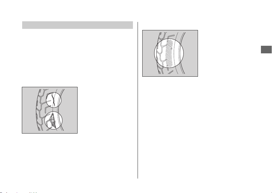
Tyres (Inspecting/Replacing)
#
Checking the Air Pressure
Visually inspect your tyres and use an air
pressure gauge to measure the air pressure at
least once a month or any time you think the
tyres look low. Always check air pressure when
your tyres are cold.
#
Inspecting for Damage
Inspect the tyres for
cuts, slits, or cracks that
exposes fabric or
cords, or nails or other
foreign objects
embedded in the side
of the tyre or the tread.
Also inspect for any unusual bumps or bulges in
the side walls of the tyres.
#
Inspecting for Abnormal Wear
Inspect the tyres for
signs of abnormal wear
on the contact surface.
Maintenance Fundamentals
Maintenance
99
Continued
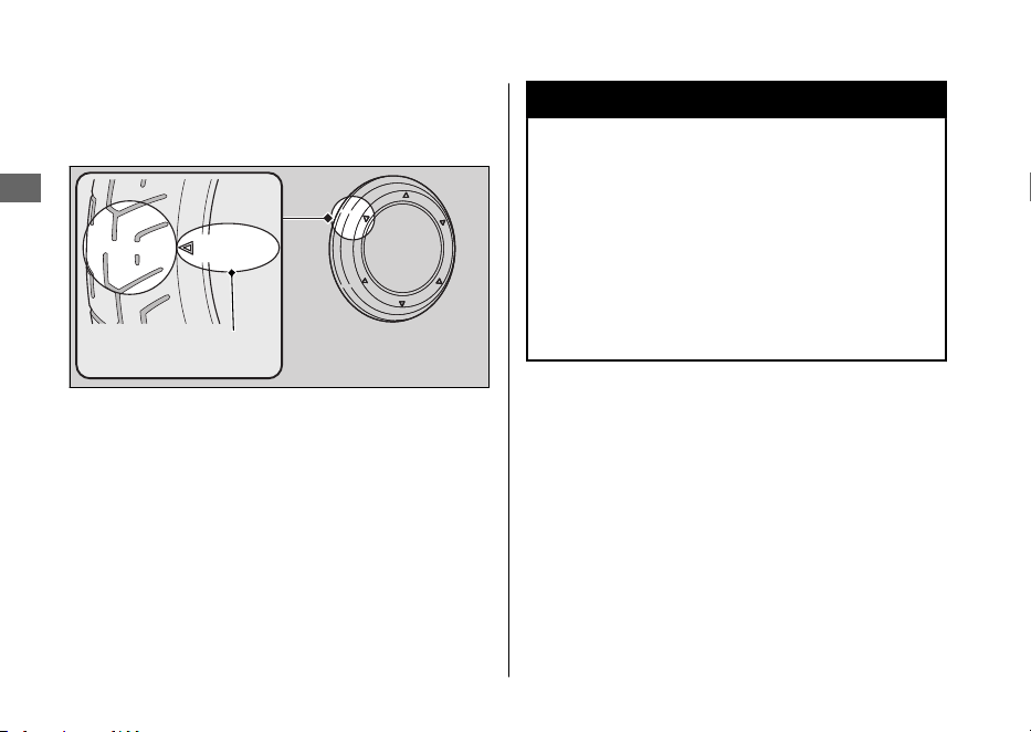
#
Inspecting Tread Depth
Inspect the tread wear indicators. If they
become visible, replace the tyres immediately.
3WARNING
Riding on tyres that are excessively
worn or improperly inflated can cause a
crash in which you can be seriously hurt
or killed.
Follow all instructions in this owner's
manual regarding tyre inflation and
maintenance.
Maintenance Fundamentals
Maintenance
100
Wear indicator
location mark
or TWI

Have your tyres replaced by your dealer.
For recommended tyres and air pressure, see
“Specifications.” 2 P. 163
Follow these guidelines whenever you replace
tyres.
● Use the recommended tyres or equivalents
of the same size, construction, speed rating,
and load range.
● Do not install a tube inside a tubeless tyre
on this vehicle. Excessive heat build-up can
cause the tube to burst.
● Use only tubeless tyres on this vehicle.
The rims are designed for tubeless tyres,
and during hard acceleration or braking, a
tube-type tyre could slip on the rim and
cause the tyre to rapidly deflate.
3WARNING
Installing improper tyres on your
vehicle can adversely affect handling
and stability, and can cause a crash in
which you can be seriously hurt or
killed.
Always use the size and type of tyres
recommended in this owner's manual.
Maintenance Fundamentals
Maintenance
101

Tool
The tool kit is stored underside of the seat.
2 P. 84
You can perform some roadside repairs, minor
adjustments and parts replacement with the
provided tools.
ED type
● 10 × 14 mm Open end wrench
● Standard/Phillips screwdriver
● Screwdriver handle
KO type
●
Spark plug wrench
●
10 × 14 mm Open end wrench
●
Standard/Phillips screwdriver
●
Screwdriver handle
Maintenance
102
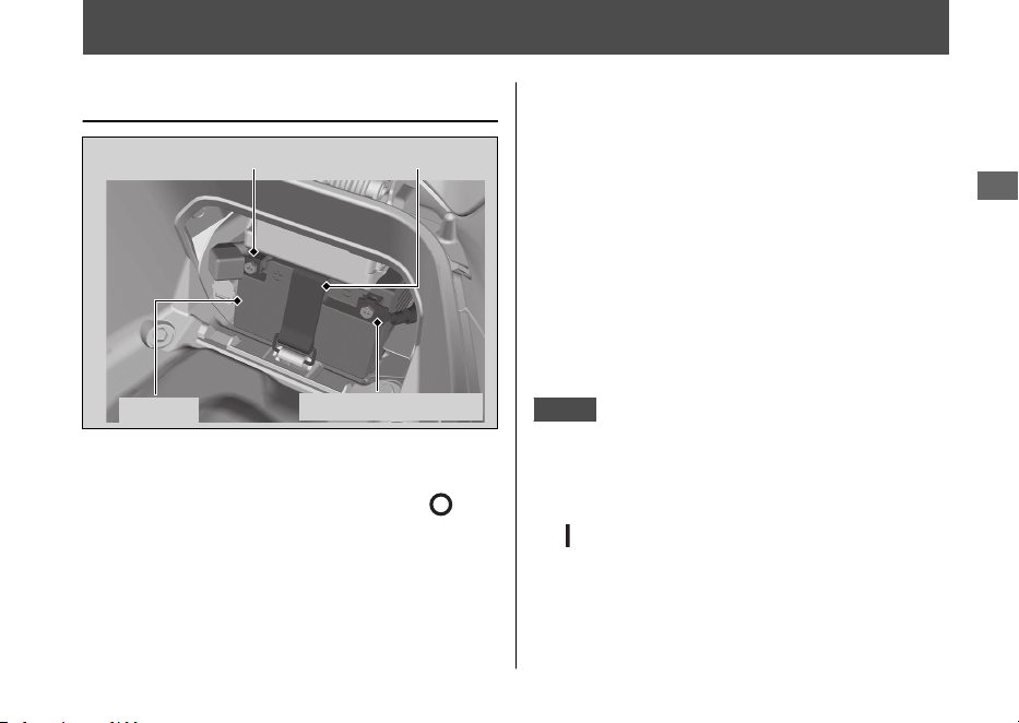
Removing & Installing Body Components
Battery
#
Removal
Make sure the ignition switch is in the
(Off) position.
1.
Remove the battery cover. 2 P. 104
2.
Unhook the rubber strap.
3.
Disconnect the negative
-
terminal from the
battery.
4.
Disconnect the positive + terminal from the
battery.
5.
Remove the battery taking care not to drop
the terminal nuts.
#
Installation
Install the parts in the reverse order of removal.
Always connect the positive + terminal first. Make
sure that bolts and nuts are tight.
Make sure the clock information is correct after
the battery is reconnected. 2 P. 33
KO type
The anti-theft alarm system will be deactivated if
the battery is disconnected. The system will remain
off when the battery is reconnected.
To activate the system, turn the ignition switch to
the (On) position once.
For proper handling of the battery, see
“Maintenance Fundamentals.” 2 P. 94
“Battery Goes Dead.” 2 P. 142
Maintenance
103
Positive terminal Rubber strap
Battery
Negative terminal
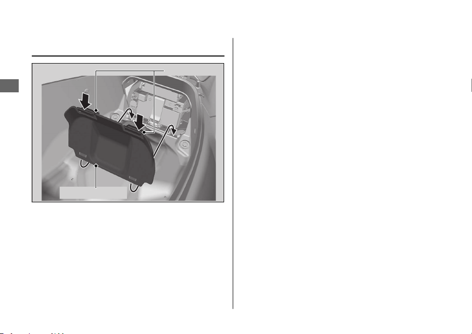
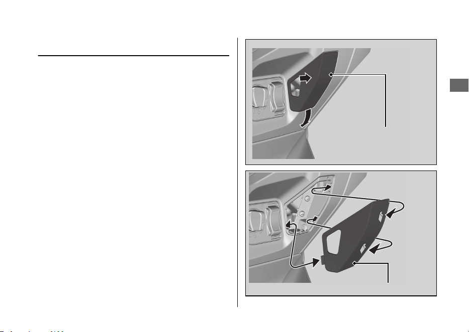
Front Lid
#
Removal
Pull out the front lid backward while pushing
the side of the front lid.
#
Installation
Install the part in the reverse order of
removal.
Make sure that all tabs are installed securely
in position.
Removing & Installing Body Components u Front Lid
Maintenance
105
Front lid
Front lid
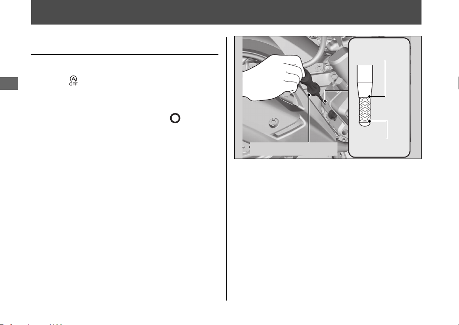
Engine Oil
Checking the Engine Oil
Check the engine oil with the Idling Stop
switch at (Idling).
1.
If the engine is cold, idle the engine for 3
to 5 minutes.
2.
Turn the ignition switch to the (Off)
position and wait for 2 to 3 minutes.
3.
Place your vehicle on its centre stand on a
firm, level surface.
4.
Remove the oil fill cap/dipstick and wipe it
clean.
5.
Insert the oil fill cap/dipstick until it seats,
but don't screw it in.
6.
Check that the oil level is between the
upper level and lower level marks on the
oil fill cap/dipstick.
7.
Securely install the oil fill cap/dipstick.
Maintenance
106
Upper level
Lower level
Oil fill cap/dipstick

Adding Engine Oil
If the engine oil is below or near the lower
level mark, add the recommended engine oil.
2 P. 96, 2 P. 163
1.
Remove the oil fill cap/dipstick. Add the
recommended oil until it reaches the
upper level mark.
u Place your vehicle on its centre stand
on a firm, level surface when checking
the oil level.
u
Do not overfill above the upper level
mark.
u
Make sure no foreign objects enter the
oil filler opening.
u
Wipe up any spills immediately.
2.
Securely reinstall the oil fill cap/dipstick.
NOTICE
Overfilling with oil or operating with insufficient
oil can cause damage to your engine. Do not mix
different brands and grades of oil.
For the recommended oil and oil selection
guidelines, see “Maintenance Fundamentals.”
2 P. 96
Engine Oil u Adding Engine Oil
Maintenance
107
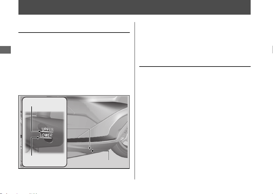
Coolant
Checking the Coolant
Check the coolant level in the reserve tank
while the engine is cold.
1.
Place your vehicle on its centre stand on a
firm, level surface.
2.
Check that the coolant level is between
the UPPER level and LOWER level marks
on the reserve tank.
If the coolant level is dropping noticeably or
the reserve tank is empty, you likely have a
serious leak. Have your vehicle inspected by
your dealer.
Adding Coolant
If the coolant level is below the LOWER level
mark, add the recommended coolant
(2 P. 98) until the level reaches the UPPER
level mark.
Add fluid only from the reserve tank cap and
do not remove the radiator cap.
1.
Pull the floor mat off.
2.
Remove the reserve tank lid by inserting a
flat head screwdriver covered with a
protective cloth into the slit on the right
side floor.
Maintenance
108
UPPER level mark
LOWER level mark
Reserve tank
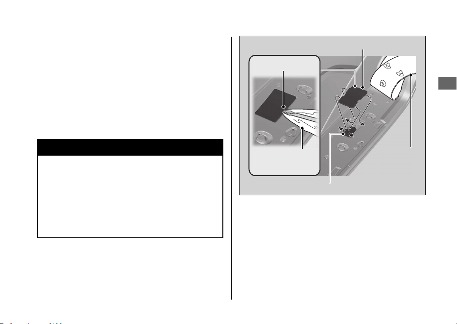
3.
Remove the reserve tank cap and add
fluid while monitoring the coolant level.
u Do not overfill above the UPPER level
mark.
u Make sure no foreign objects enter the
reserve tank opening.
4.
Securely reinstall the reserve tank cap.
5.
Install the reserve tank lid and floor mat.
3WARNING
Removing the radiator cap while the
engine is hot can cause the coolant to
spray out, potentially scalding you.
Always let the engine and radiator cool
down before removing the radiator cap.
Coolant u Adding Coolant
Maintenance
109
Reserve tank cap
Reserve tank lid
Floor mat
Slit
Protective
cloth
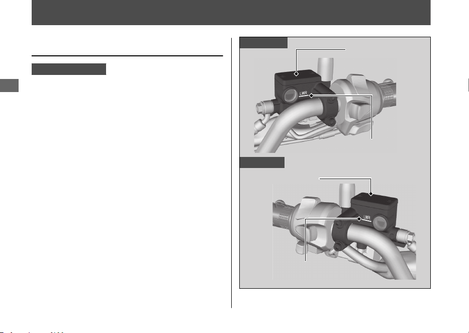
Brakes
Checking Brake Fluid
WW125A KO type
1.
Place your vehicle in an upright position
on a firm, level surface.
2.
Check that the brake fluid reservoir is
horizontal and that the fluid level is above
the LWR mark.
If the brake fluid level in either reservoir is
below the LWR mark or both the brake levers
freeplay becomes excessive, inspect the
brake pads for wear.
If the brake pads are not worn, you most
likely have a leak. Have your vehicle
inspected by your dealer.
Maintenance
110
Front brake
Rear brake
Front brake fluid
reservoir
LWR mark
LWR mark
Rear brake fluid
reservoir
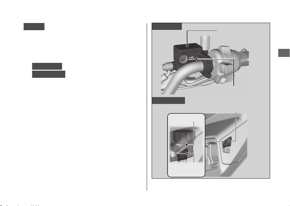
WW125
1.
Place your vehicle in an upright position
on a firm, level surface.
2.
Check that the brake fluid reservoir is
horizontal and that the fluid level is:
Front brake
above the LWR mark.
Combi brake
between the LOWER level
and UPPER level marks.
If the brake fluid level in either reservoir is
below the LWR mark or LOWER level mark or
the brake lever freeplay becomes excessive,
inspect the brake pads for wear.
If the brake pads are not worn, you most
likely have a leak. Have your vehicle
inspected by your dealer.
Brakes u Checking Brake Fluid
Maintenance
111
Front brake
Combi brake
CBS brake fluid reservoir
UPPER level
mark
LOWER level
mark
LWR mark
Front brake fluid
reservoir
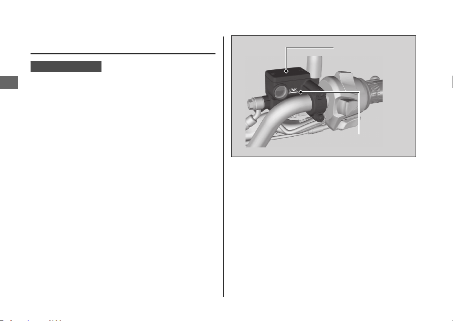
Checking the Front Brake Fluid
WW125A ED type
1.
Place your vehicle in an upright position
on a firm, level surface.
2.
Check that the brake fluid reservoir is
horizontal and that the fluid level is above
the LWR mark.
If the brake fluid level in the reservoir is
below the LWR mark or the brake lever
freeplay becomes excessive, inspect the
brake pads for wear.
If the brake pads are not worn, you most
likely have a leak. Have your vehicle
inspected by your dealer.
Brakes u Checking the Front Brake Fluid
Maintenance
112
LWR mark
Front brake fluid
reservoir
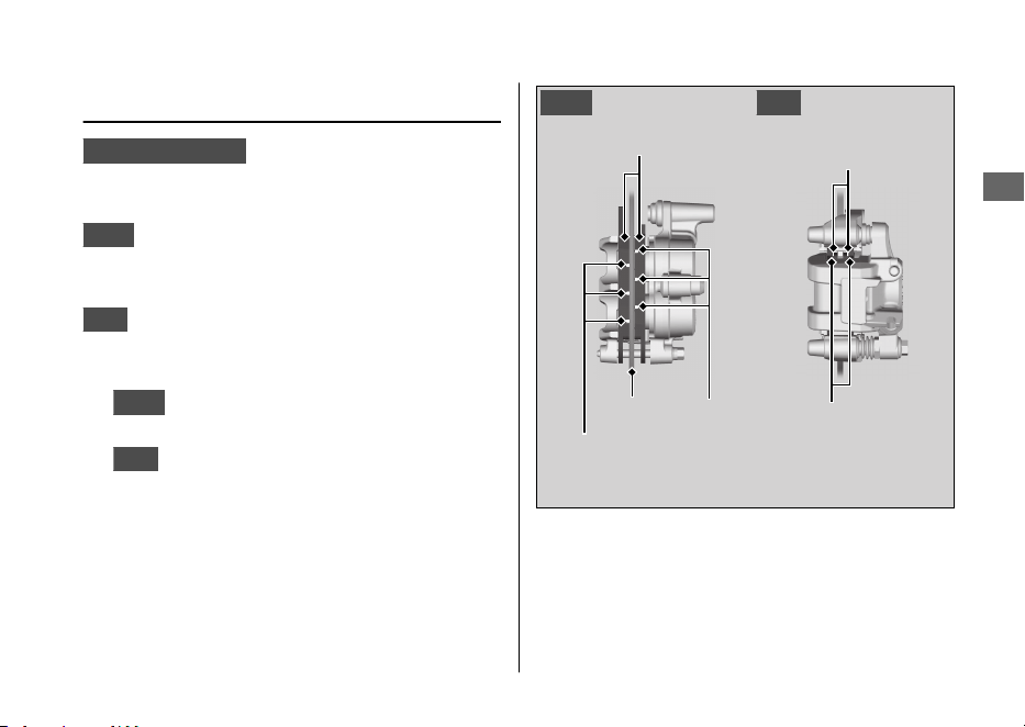
Inspecting the Brake Pads
WW125A KO type
Check the condition of the brake pad wear
indicators.
Front
The pads need to be replaced if a
brake pad is worn to the bottom of the
indicator.
Rear
The pads need to be replaced if a brake
pad is worn to the indicator.
1.
Front
Inspect the brake pads from in front
of the brake caliper.
2.
Rear
Inspect the brake pads from the rear
right of the vehicle.
If necessary have the pads replaced by your
dealer.
Always replace both left and right brake pads
at the same time.
Brakes u Inspecting the Brake Pads
Maintenance
113
Brake pads
Wear
indicators
Disc
Wear
indicators
RearFront
Brake pads
Wear
indicators
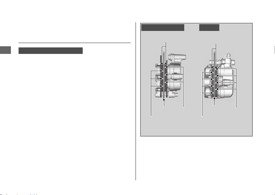
Inspecting the Front Brake
Pads
WW125, WW125A ED type
Check the condition of the brake pad wear
indicators.
The pads need to be replaced if a brake pad
is worn to the bottom of the indicator.
1.
Inspect the brake pads from in front of
the brake caliper.
If necessary have the pads replaced by your
dealer.
Always replace both left and right brake pads
at the same time.
Brakes u Inspecting the Front Brake Pads
Maintenance
114
Brake pads
Wear
indicators
Disc
Wear
indicators
WW125WW125A ED type
Wear
indicators
Disc
Wear
indicators
Brake pads
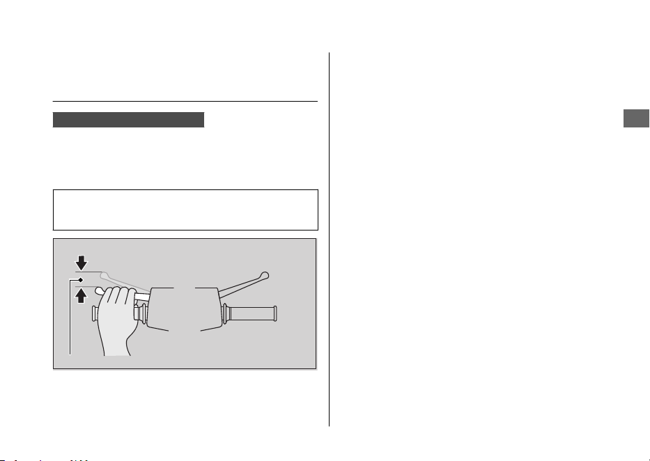
Inspecting the Rear Brake Lever
Freeplay
WW125, WW125A ED type
1.
Place the vehicle on its centre stand.
2.
Measure the distance the rear brake lever
moves before the brake takes hold.
Freeplay at the tip of the brake lever:
10 - 20 mm (0.4 - 0.8 in)
Check the brake cable for kinks or signs of
wear. If necessary have it replaced by your
dealer.
Lubricate the brake cable with a
commercially available cable lubricant to
prevent premature wear and corrosion.
Make sure the brake arm, spring and fastener
are in good condition.
Brakes u Inspecting the Rear Brake Lever Freeplay
Maintenance
115
Freeplay
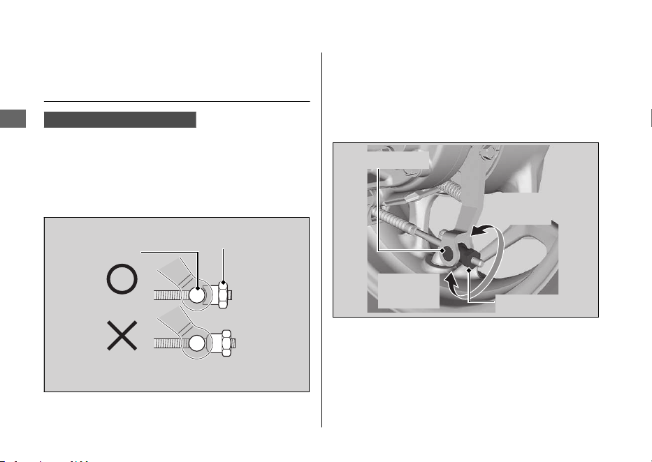
Adjusting the Rear Brake Lever
Freeplay
WW125, WW125A ED type
Adjust the freeplay of the brake lever with the
front wheel pointed straight ahead.
Make sure the cut-out on the adjusting nut is
seated on the brake arm pin when adjusting
the freeplay.
If proper adjustment cannot be obtained by
this method, see your dealer.
1.
Adjust by turning the rear brake adjusting
nut a half-turn at a time.
2.
Apply the brake several times and check
for free wheel rotation after the brake
lever is released.
Brakes u Adjusting the Rear Brake Lever Freeplay
Maintenance
116
Adjusting nut
Brake arm pin
Brake arm pin
Increase
Freeplay
Decrease
Freeplay
Adjusting nut
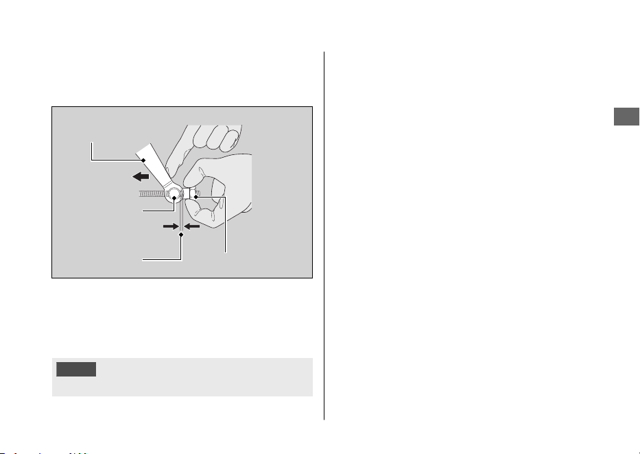
3.
Push the brake arm to confirm that there
is a gap between the rear brake adjusting
nut and brake arm pin.
After adjustment, confirm the freeplay of the
brake lever.
Make sure the brake arm, spring and fastener
are in good condition.
NOTICE
Do not turn the adjuster beyond its natural limits.
Brakes u Adjusting the Rear Brake Lever Freeplay
Maintenance
117
Adjusting nut
Gap
Brake arm pin
Push
Brake arm
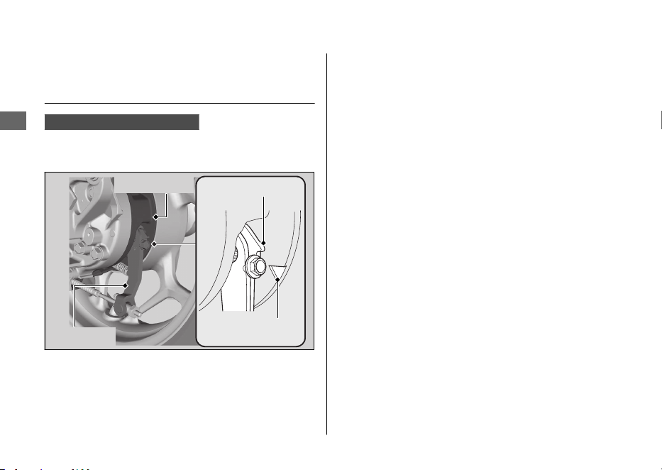
Inspecting the Rear Brake Shoe
Wear
WW125, WW125A ED type
The rear brake is equipped with a brake wear
indicator.
When the brake is applied, an arrow attached
to the brake arm moves toward a reference
mark on the brake panel. If the arrow aligns
with the reference mark on full application of
the brake, the brake shoes must be replaced.
See your dealer for this service.
When the brake service is necessary, see your
dealer. Use only Honda Genuine Parts or its
equivalent.
Brakes u Inspecting the Rear Brake Shoe Wear
Maintenance
118
Brake arm
Brake panel
Arrow
Reference mark
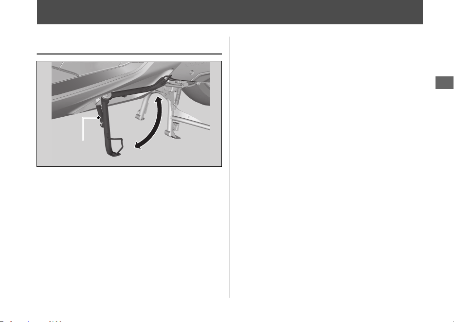
Side Stand
Checking the Side Stand
1.
Place your vehicle on its centre stand on a
firm, level surface.
2.
Check that the side stand operates
smoothly. If the side stand is stiff or
squeaky, clean the pivot area and
lubricate the pivot bolt with clean grease.
3.
Check the spring for damage or loss of
tension.
4.
Sit on the vehicle and raise the side stand.
5.
Start the engine.
6.
Lower the side stand all the way. The
engine should stop as you lower the side
stand. If the engine doesn't stop, have
your vehicle inspected by your dealer.
Maintenance
119
Side stand
spring
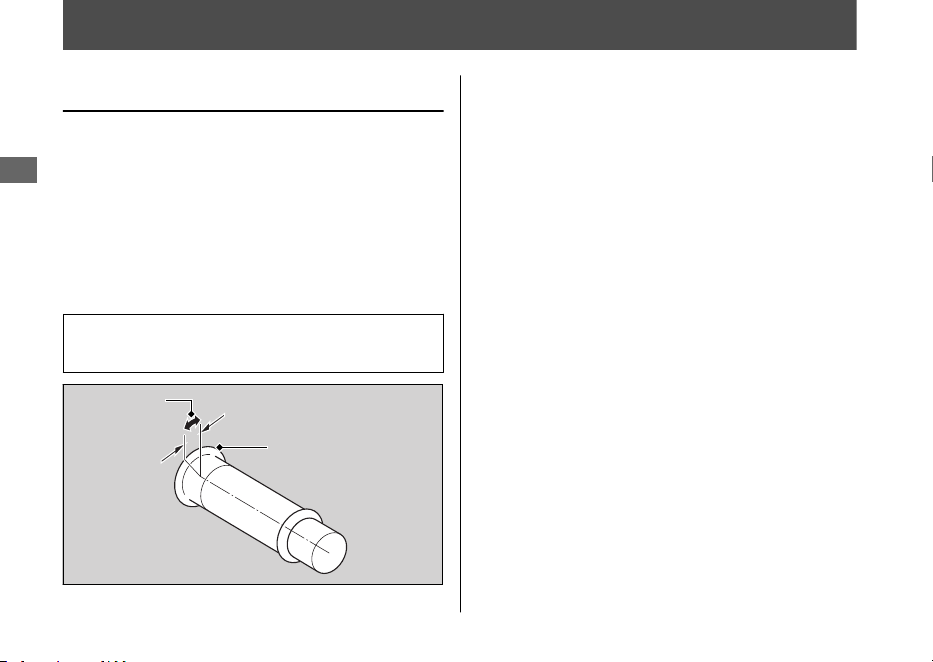
Throttle
Checking the Throttle
With the engine off, check that the throttle
rotates smoothly from fully closed to fully
open in all steering positions and throttle
freeplay is correct. If the throttle does not
move smoothly, close automatically, or if the
cable is damaged, have the vehicle inspected
by your dealer.
Freeplay at the throttle grip flange:
2 - 6 mm (0.1 - 0.2 in)
Maintenance
120
Freeplay
Flange
Other Replacement
Replacing the Honda SMART
Key Battery
If the Honda SMART Key indicator flashes 5
times when the ignition switch is turned
(On), or the operating range becomes
unstable, replace the battery as soon as
possible.
We recommend to see your dealer for this
service.
Battery type: CR2032
1.
Remove the upper case by inserting a
coin or a flat head screwdriver covered
with a protective cloth into the slit.
u Wrap a coin or a screwdriver with a
protective cloth to prevent scratching
the Honda SMART Key.
u Do not touch the circuit or terminal.
This may cause problems.
u Be careful to avoid scratching the
waterproof covering or allowing dust
to enter.
u
Do not forcibly dismantle the Honda
SMART Key body.
Maintenance
121
Continued
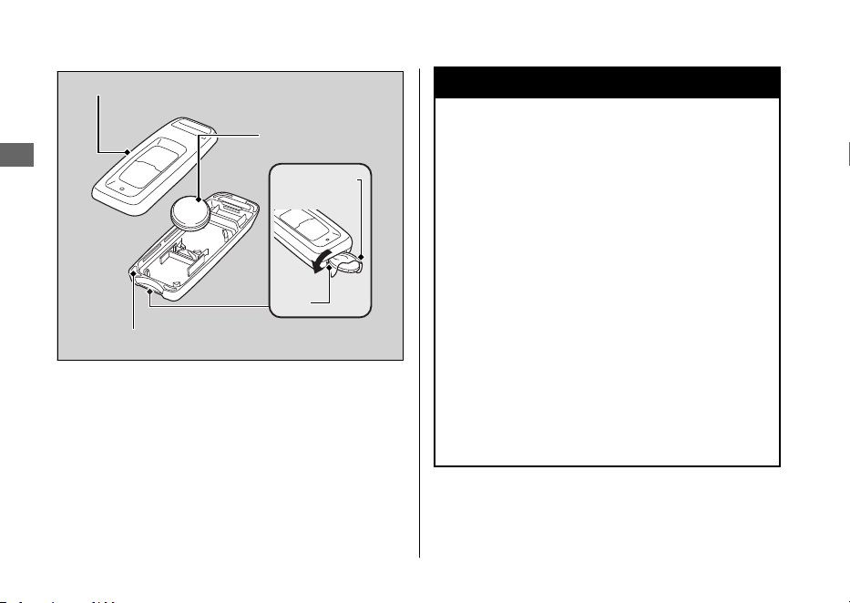
2.
Replace the old battery with a new
battery with the negative
-
side facing
up.
3.
Snap the two halves of the Honda SMART
Key back together.
u
Make sure that upper and lower cases
are set in the right position.
3WARNING
Chemical Burn Hazard: do not
swallow battery.
If swallowed, the battery can cause
severe internal burns and even death.
•
Keep battery away from children and
battery compartment securely
closed.
•
If the battery compartment does not
close securely, stop using the
product and keep it away from
children.
•
Immediately seek medical attention
if a child may have swallowed
battery.
Other Replacement u Replacing the Honda SMART Key Battery
Maintenance
122
Upper case
Battery
Lower case
Slit
Protective
cloth

CAUTION: Danger of explosion if battery is
incorrectly replaced. Replace only with the
same or equivalent type.
CAUTION: Do not exposed to excessive heat
such as sunshine, fire or the like, that can
result in an explosion or the leakage of
flammable liquid or gas during use, storage
or transportation.
CAUTION: Do not dispose of a battery into
fire or a hot oven, or give mechanically
crushing or cutting of a battery, that can
result in an explosion.
CAUTION: Do not subjected to extremely
low air pressure at high altitude that may
result in an explosion or the leakage of
flammable liquid or gas.
Other Replacement u Replacing the Honda SMART Key Battery
Maintenance
123

Engine Will Not Start......................................P. 125
Overheating (High coolant temperature
indicator is on)............................................... P. 126
Warning Indicators On or Flashing............. P. 127
PGM-FI (Programmed Fuel Injection)
Malfunction Indicator Lamp (MIL)............... P. 127
Battery Charging Condition indicator .......... P. 127
ABS (Anti-lock Brake System) Indicator ....... P. 128
Torque Control Indicator................................. P. 129
Honda SMART Key Indicator.......................... P. 130
Other Warning Indications ........................... P. 131
Fuel Gauge Failure Indication......................... P. 131
When the Idling Stop System Does Not
Operate Properly........................................... P. 132
Idling Stop Indicator Does Not Come On .. P. 132
Engine is Not Stopped by the Idling Stop System
While the Idling Stop Indicator is On......... P. 133
Engine Does Not Start Even If the Throttle is
Opened ............................................................. P. 134
When the Honda SMART Key System Does Not
Operate Properly........................................... P. 135
Unlock the Seat in an Emergency ............... P. 137
Unlock the Ignition Switch in an
Emergency ...................................................... P. 138
Tyre Puncture ................................................... P. 141
Electrical Trouble............................................. P. 142
Battery Goes Dead............................................ P. 142
Burned-out Light Bulb ..................................... P. 142
Blown Fuse..........................................................P. 143
Unstable Engine Operation Occurs
Intermittently ................................................. P. 145
Troubleshooting

Engine Will Not Start
Starter Motor Operates But
Engine Does Not Start
Check the following items:
● Check the correct engine starting
sequence. 2 P. 73
●
Check that there is petrol in the fuel tank.
● Check if the PGM-FI malfunction indicator
lamp (MIL) is on.
u If the indicator lamp is on, contact
your dealer as soon as possible.
Starter Motor Does Not
Operate
Check the following items:
● Check the correct engine starting
sequence. 2 P. 73
●
Check for a blown fuse. 2 P. 143
● Check for a loose battery connection
(2 P. 103) or battery terminal corrosion
(2 P. 94).
● Check the condition of the battery.
2 P. 142
If the problem continues, have your vehicle
inspected by your dealer.
Troubleshooting
125

Overheating (High coolant temperature indicator is on)
The engine is overheating when the following
occurs:
● High coolant temperature indicator
comes on.
● Acceleration becomes sluggish.
If this occurs, pull safely to the side of the
road and perform the following procedure.
Extended fast idling may cause the high
coolant temperature indicator to come on.
NOTICE
Continuing to ride with an overheated engine
can cause serious damage to the engine.
1.
Stop the engine using the ignition switch.
2.
Allow the engine to cool with the ignition
switch in the (Off) position.
3.
After the engine has cooled, inspect the
radiator hose and check if there is a leak.
2 P. 108
If there is a leak:
Do not start the engine. Transport your
vehicle to your dealer.
4.
Check the coolant level in the reserve
tank. 2 P. 108
u
Add coolant as necessary.
5.
If 1-4 check normal, you may continue
riding, but closely monitor the high
coolant temperature indicator.
Troubleshooting
126

Warning Indicators On or Flashing
PGM-FI (Programmed Fuel
Injection) Malfunction
Indicator Lamp (MIL)
If the indicator comes on while riding, you
may have a serious problem with the PGM-FI
system. Reduce speed and have your vehicle
inspected by your dealer as soon as possible.
Battery Charging Condition
indicator
If the indicator comes on while riding, you
may have a condition of low battery voltage
or battery performance degradation. Have
your vehicle inspected by your dealer.
u If the battery does not have enough
voltage to drive the indicator system, the
indicator may not come on.
Troubleshooting
127

ABS (Anti-lock Brake System)
Indicator
WW125A
If the indicator operates in one of the
following ways, you may have a serious
problem with the ABS. Reduce your speed
and have your vehicle inspected by your
dealer as soon as possible.
●
Indicator comes on or starts flashing while
riding.
●
Indicator does not come on when the
ignition switch is turned to the
(On)
position.
● Indicator does not go off at speeds above
10 km/h (6 mph).
If the ABS indicator stays on, your brakes will
continue to work as a conventional system,
but without the anti-locking function.
The ABS indicator may flash if you turn the
rear wheel while the rear wheel is lifted off
the ground. In this case, turn the ignition
switch to the (Off) position, and then to
the (On) position again. The ABS indicator
will go off after your speed reaches 30 km/h
(19 mph).
Warning Indicators On or Flashing u ABS (Anti-lock Brake System) Indicator
Troubleshooting
128

Torque Control Indicator
WW125A
If the indicator operates in one of the
following ways, you may have a serious
problem with the Torque Control. Reduce
your speed and have your vehicle inspected
by your dealer as soon as possible.
●
Indicator comes and stays on (solid) while
riding.
● Indicator does not come on when the
ignition switch is turned to the (On)
position.
●
Indicator does not go off at speeds above
3 km/h (2 mph).
Even when the Torque Control indicator is
on, your vehicle will have normal riding ability
without Torque Control function.
u When the indicator comes on while the
Torque Control is in operation, you will
have to completely close the throttle to
regain normal riding ability.
The Torque Control indicator may come on if
you rotate the rear wheel while your vehicle
is lifted off the ground. In this case, turn the
ignition switch to the
(Off) position, and
then to the (On) position again. The Torque
Control indicator will go off after your speed
reaches 3 km/h (2 mph).
Warning Indicators On or Flashing u Torque Control Indicator
Troubleshooting
129
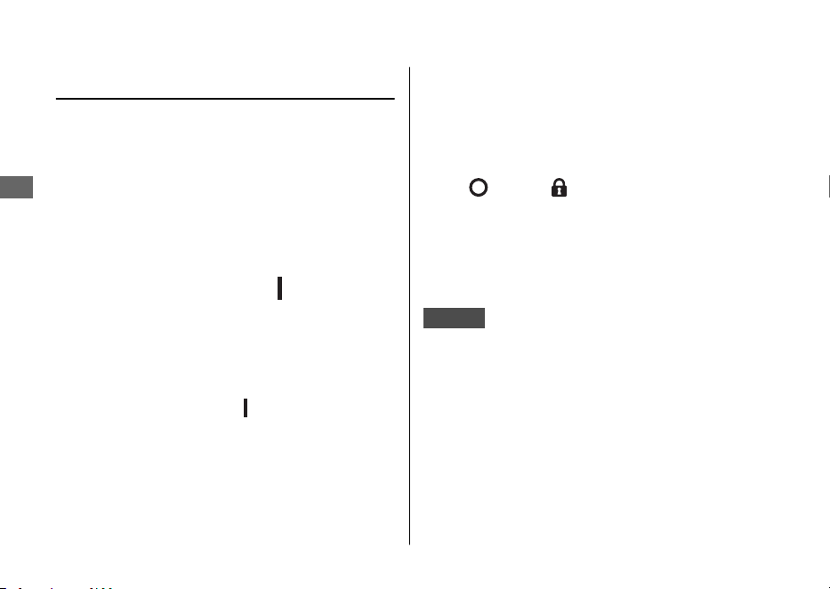
Honda SMART Key Indicator
#
When the Honda SMART Key
indicator flashes 5 times
Replacing the Honda SMART Key
Battery 2 P. 121
#
When the Honda SMART Key
indicator is flashing while the
ignition switch is in the (On)
position
The Honda SMART Key indicator flashes
when communication between your vehicle
and Honda SMART Key stops after turning
the ignition switch to the (On) position.
It is probably caused by the following:
● Strong radio waves or noise are affecting
the system
● You lose the Honda SMART Key while
riding
However, this does not affect the operation
of your vehicle until stop the engine except
the idling stop.
If you turn the ignition switch to the SEAT
FUEL, (Off) or (Lock) position while the
Honda SMART Key indicator is flashing, the
ignition switch ring, turn signals and the
Honda SMART Key indicator will come on for
about 20 seconds, automatically go off, and
then the ignition switch will lock.
KO type
The buzzer also rings at this time.
To stop this flashing and ringing, press and
hold the ignition switch for more than 2
seconds. After the flashing and ringing stop,
the ignition switch is locked.
If you do not have the Honda SMART Key,
the ignition switch can be unlocked in
another way. 2 P. 138
Warning Indicators On or Flashing u Honda SMART Key Indicator
Troubleshooting
130
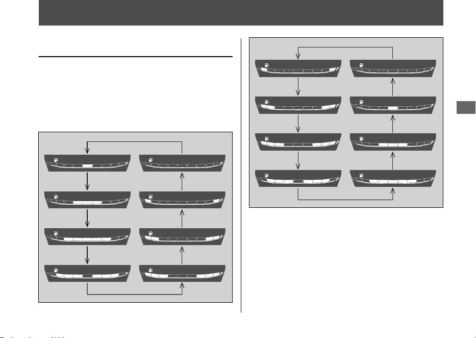
Other Warning Indications
Fuel Gauge Failure Indication
If the fuel system has an error, the fuel gauge
indicators will be displayed as shown in the
illustrations.
If this occurs, see your dealer as soon as
possible.
Troubleshooting
131
When the Idling Stop System Does Not Operate Properly
Idling Stop Indicator Does Not
Come On
When the Idling Stop indicator does not
come on, perform the followings.
If the Idling Stop switch is at (Idling):
Press the Idling Stop switch to (Idling
Stop).
If the engine is cold:
Warm up the engine.
The Idling Stop system does not operate
when the engine is cold.
If you did not ride the vehicle after engine
starts:
Ride the vehicle at speeds of over 10 km/h (6
mph). The Idling Stop system does not
operate until you ride once.
If PGM-FI malfunction indicator lamp (MIL)
lights:
When the PGM-FI malfunction indicator lamp
(MIL) lights, the Idling Stop system does not
operate for protection of the engine. See
your dealer.
If the battery voltage is low:
Ride the vehicle awhile, then stop the engine
and then restart the engine with start button
referring to the starting procedure (2 P. 73)
for standard engine starting. The Idling Stop
system may not operate if the battery voltage
is low.
If this occurs frequently, contact your dealer.
Troubleshooting
132

Engine is Not Stopped by the
Idling Stop System While the
Idling Stop Indicator is On
When the engine is not stopped by the Idling
Stop system while the Idling Stop indicator is
on, perform the followings.
If the vehicle does not stop completely:
Stop the vehicle completely. The Idling Stop
system operates if the speed is only at 0
km/h (0 mph).
If the throttle is not closed completely:
Close the throttle completely.
When the Idling Stop System Does Not Operate Properly u Engine is Not Stopped by the Idling Stop System While the Idling Stop Indicator is On
Troubleshooting
133
Engine Does Not Start Even If
the Throttle is Opened
Engine does not start even if the throttle is
opened, perform the followings.
If the side stand is down:
While the engine is stopped by the Idling
Stop system, if you operate the side stand,
the flashing Idling Stop indicator turns off or
stops flashing and stays on, and the Idling
Stop system is cancelled. Restart the engine
with start button referring to the starting
procedure (2 P. 73) for standard engine
starting.
If the Idling Stop switch is at (Idling):
While the engine is stopping by the Idling
Stop system, if you press the Idling Stop
switch to
(Idling), the Idling Stop system
will be cancelled. Restart the engine with start
button referring to the starting procedure
(2 P. 73) for standard engine starting.
If the Idling Stop indicator flashes (the Idling
Stop switch is at
(Idling Stop) position),
but engine does not start even if the throttle
is opened, perform the followings.
Low (or dead) battery or battery lead is loose:
Check the battery and battery terminals. If
the battery is weak, contact your dealer.
When the Idling Stop System Does Not Operate Properly u Engine Does Not Start Even If the Throttle is Opened
Troubleshooting
134

When the Honda SMART Key System Does Not Operate Properly
When the Honda SMART Key system does
not work properly, perform the following.
● Check that the Honda SMART Key system
is activated.
Lightly push the ON/OFF button on the
Honda SMART Key.
If the Honda SMART Key LED is red,
activate the Honda SMART Key system.
2 P. 48
If the Honda SMART Key LED does not
respond, replace the battery.
● Check that there is no communication
failure in the Honda SMART Key system.
The Honda SMART Key system uses low-
intensity radio waves. The Honda SMART
Key system may not work properly in the
following conditions:
u When there are facilities nearby that
generate strong radio waves or noise
such as TV towers, power stations,
radio stations, or airports.
u
When you carry the Honda SMART
Key with a laptop or wireless
communication device such as a radio
or mobile phone.
u
When the Honda SMART Key comes
into contact with or is covered by
metal objects.
Troubleshooting
135
Continued

● Check that a registered Honda SMART
Key is used.
Use a registered Honda SMART Key.
The Honda SMART Key system cannot be
activated without a registered Honda
SMART Key.
● Make sure that you do not use a broken
Honda SMART Key.
If you use a broken Honda SMART Key,
the Honda SMART Key system cannot be
activated. Bring the emergency key and
ID tag to your dealer.
● Check the battery condition and battery
lead in your vehicle.
Check the battery and battery terminals. If
the battery is weak, contact your dealer.
If the Honda SMART Key system cannot be
activated due to other causes, contact your
dealer.
When the Honda SMART Key System Does Not Operate Properly
Troubleshooting
136
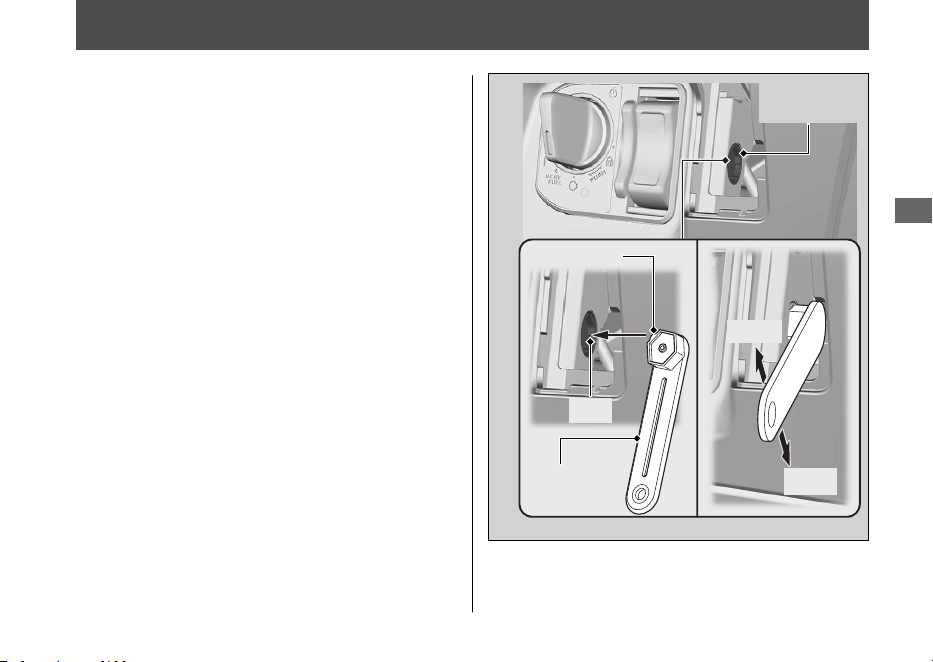
Unlock the Seat in an Emergency
The seat lock can be unlocked by using the
emergency key.
#
Open
1.
Remove the front lid. 2 P. 105
2.
Align the projection of the emergency key
with the slot of the emergency seat
opener, and turn the emergency key
counterclockwise.
3.
Open the seat and turn the emergency
key clockwise
#
Close
1.
Close and push down on the rear of the
seat until it locks. Make sure that the seat
is locked securely by pulling it up lightly. If
the seat is not locked, turn the emergency
key clockwise to lock the seat catch.
2.
Install the front lid.
Troubleshooting
137
Emergency
key
Open
Close
Emergency
seat opener
Projection
Slot
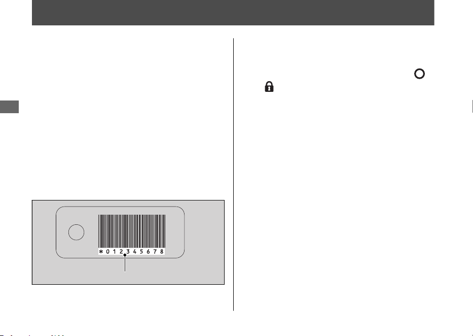
Unlock the Ignition Switch in an Emergency
#
Set up to ID number input mode
1.
Press and hold the ignition switch for
more than 4 seconds.
u The ignition switch ring and the Honda
SMART Key indicator flash.
2.
Check the ID number on the ID tag.
3.
Press the ignition switch while the ignition
switch ring and the Honda SMART Key
indicator are flashing.
u The ignition switch ring and the Honda
SMART Key indicator stay lit, and the
ID number input mode turns on.
#
ID number input
You can input your ID number by pressing the
ignition switch when the ignition switch is
(Off), (Lock) and SEAT FUEL position. Input
the ID number on the ID tag in order from the
left in turn by pressing the ignition switch.
The ID number is authenticated according to
the number of times the ignition switch is
pushed.
Push the ignition switch the desired number
of times within 5 seconds when the ignition
switch ring comes on. After 5 seconds, the
ignition switch ring goes off and comes on
again. This means that the inputted number
is fixed, and you can input the next number.
u
If the ignition switch ring does not come
on in blue, the battery may be low.
Contact your dealer.
Troubleshooting
138
ID number
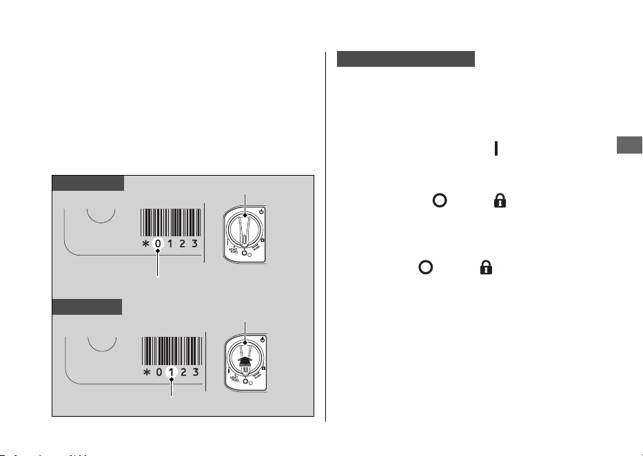
Example:
● To input “0”, wait for 5 seconds without
pushing the ignition switch when the
ignition switch ring comes on.
● To input “1”, push the ignition switch once
within 5 seconds when the ignition switch
ring comes on.
ID number input success
After the last ID number is input, the ignition
switch ring and the Honda SMART Key
indicator go off, and when they come on
again the ignition switch is unlocked.
Turn the ignition switch to the (On) position
within 6 minutes. You can start the engine.
To lock the ignition switch, turn the ignition switch
to the SEAT FUEL, (Off), or (Lock) position,
and press and hold the ignition switch for 2
seconds. The ignition switch also locks
automatically when the ignition switch has been in
the SEAT FUEL, (Off), or (Lock) position for
about 6 minutes after the ID number is
successfully inputted.
When the ignition switch is locked, the ignition
switch ring goes off.
To unlock the ignition switch again, repeat the
procedure for unlocking the ignition switch.
Unlock the Ignition Switch in an Emergency
Troubleshooting
139
Continued
To input “0”
To input “1”
ID number
Ignition switch
No push
Ignition switch
ID number
Push one time

ID number input failure
After the last ID number is input, the ignition
switch ring and the Honda SMART Key
indicator flash at 1 second intervals, and then
go off.
The ignition switch does not unlock.
Redo the “Unlock the Ignition Switch in an
Emergency” procedure. 2 P. 138
ID number input cancel
If you make a mistake while inputting your ID,
do not press the ignition switch, just wait for
the ignition switch ring and the Honda
SMART Key indicator to turn off.
Redo the “Unlock the Ignition Switch in an
Emergency” procedure. 2 P. 138
Unlock the Ignition Switch in an Emergency
Troubleshooting
140

Tyre Puncture
Repairing a puncture or removing a wheel
requires special tools and technical expertise.
We recommend you have this type of service
performed by your dealer.
After an emergency repair, always have the
tyre inspected/replaced by your dealer.
Emergency Repair Using a Tyre
Repair Kit
If your tyre has a minor puncture, you can
make an emergency repair using a tubeless
tyre repair kit.
Follow the instructions provided with the
emergency tyre repair kit.
Riding your vehicle with a temporary tyre
repair is very risky. Do not exceed 50 km/h
(30 mph). Have the tyre replaced by your
dealer as soon as possible.
3WARNING
Riding your vehicle with a temporary
tyre repair can be risky. If the temporary
repair fails, you can crash and be
seriously injured or killed.
If you must ride with a temporary tyre
repair, ride slowly and carefully and do
not exceed 50 km/h (30 mph) until the
tyre is replaced.
Troubleshooting
141
Electrical Trouble
Battery Goes Dead
Charge the battery using a motorcycle
battery charger.
Remove the battery from the vehicle before
charging.
Do not use an automobile-type battery
charger, as these can overheat a motorcycle
battery and cause permanent damage. If the
battery does not recover after recharging,
contact your dealer.
NOTICE
Jump starting using an automobile battery can
damage your vehicle's electrical system and is
not recommended.
Burned-out Light Bulb
All light bulbs on the vehicle are LEDs. If
there is an LED which is not turned on, see
your dealer for servicing.
The headlight/front turn signal lights/position
lights/brakelights/taillights/rear turn signal
lights/license plate light use several LEDs. If
there is a LED which is not turned on, see
your dealer for servicing.
Troubleshooting
142
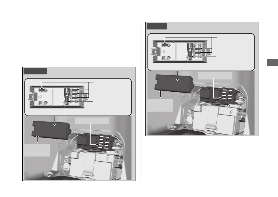

1.
Remove the battery cover. 2 P. 104
2.
Open the fuse box cover.
3.
Pull the main fuse and other fuses out
one by one with the fuse puller located
inside of the fuse box cover. Check for a
blown fuse. Always replace a blown fuse
with a spare fuse of the same rating.
4.
Install the fuse box cover.
5.
Install the battery cover.
NOTICE
If a fuse fails repeatedly, you likely have an
electrical problem. Have your vehicle inspected
by your dealer.
Electrical Trouble u Blown Fuse
Troubleshooting
144

Unstable Engine Operation Occurs Intermittently
If the fuel pump filter is clogged, unstable
engine operation will occur intermittently
while riding.
Even if this symptom occurs, you can
continue to ride your vehicle.
If unstable engine operation occurs even if
sufficient fuel is available, have your vehicle
inspected by your dealer as soon as possible.
Troubleshooting
145

Service Diagnostic Recorders....................... P. 147
Keys..................................................................... P. 147
Instruments, Controls, & Other Features...P. 151
Caring for Your Vehicle.................................. P. 152
Storing Your Vehicle.......................................P. 156
Transporting Your Vehicle ............................P. 157
You & the Environment ................................. P. 158
Serial Numbers ................................................ P. 159
Fuels Containing Alcohol .............................. P. 160
Catalytic Converter ......................................... P. 161
Information
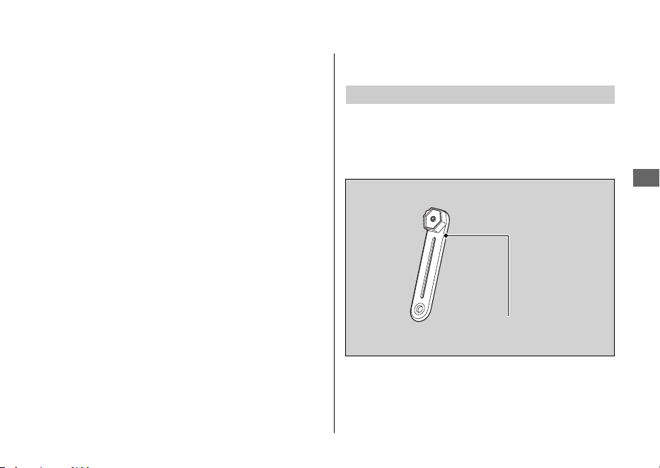
Service Diagnostic
Recorders
Your vehicle is equipped with service-related
devices that record information about
powertrain performance and riding conditions.
The data can be used to help technicians
diagnose, repair and maintain the vehicle. This
data may not be accessed by anyone else
except as legally required or with the permission
of the vehicle owner.
However this data may be accessed by Honda,
its authorised dealers and authorised repairers,
employees, representatives and contractors only
for the purpose of the technical diagnosis,
research and development of the vehicle.
Keys
Emergency Key
The emergency key is used for an emergency.
● To unlock the seat. 2 P. 137
Do not store the emergency key in any
compartment.
Service Diagnostic Recorders
Information
147
Continued
Emergency key

Honda SMART Key
Carrying the Honda SMART Key allows you to
perform the following operations:
● Locking or unlocking the ignition switch
● Releasing the seat lock
● Opening the fuel lid
● Locking or unlocking the steering
The ID number of the Honda SMART Key is on
the ID tag. You can also unlock the ignition
switch by inputting the ID number.
Always carry both the emergency key and ID
tag, but separate from the Honda SMART Key,
to avoid losing all of them at the same time.
Also store a copy of your ID number in a safe
place other than your vehicle.
The Honda SMART Key contains electronic
circuits. If the circuits are damaged, the Honda
SMART Key will not allow you to perform any
operations.
● Do not drop the Honda SMART Key or set
heavy objects on them.
● Protect the Honda SMART Key from direct
sunlight, high temperature, and high
humidity.
● Do not scratch or puncture.
● Do not store near any magnetized products
such as a magnetized key chain.
●
Always keep the Honda SMART Key away
from electric appliances such as a TV, radio,
PC or low-frequency massage device.
●
Keep the Honda SMART Key away from
liquids. If it gets wet, dry it immediately with
a soft cloth.
●
Keep the Honda SMART Key away from the
vehicle while washing the vehicle.
●
Do not burn.
●
Do not wash in an ultrasonic cleaner.
Keys
Information
148
● If fuel, wax, or grease adhere to the Honda
SMART Key, wipe it off immediately to avoid
cracking or warping.
● Do not disassemble the Honda SMART Key
other than when changing a battery. Only
the cover of the Honda SMART Key can be
disassembled. Do not disassemble other
parts.
● Do not lose your Honda SMART Key. If you
lose it, you will need to register a new
Honda SMART Key. See your dealer with
your emergency key and ID tag for
registration.
The battery in the Honda SMART Key system
normally lasts about 2 years.
Do not keep mobile phones or other radio
transmitting devices in any compartment. The
radio frequency from the devices will interrupt
the Honda SMART Key system.
To get an additional Honda SMART Key, take
the Honda SMART Key and the vehicle to your
dealer.
EU Directive
This Honda SMART Key system complies with
the RE (Radio Equipment) Directive (2014/53/
EU).
The declaration of conformity to RE Directive is
provided to the owner at the time of purchase.
The declaration of conformity should be kept at
a safe place. When the declaration of
conformity is lost or is not provided, contact
your dealer.
Korea only
Keys
Information
149
Continued
Honda Lock Mfg. Co., Ltd.
Smart system
HLSS-6A, HLSS-6B
Honda Lock Mfg. Co., Ltd.
Vietnam
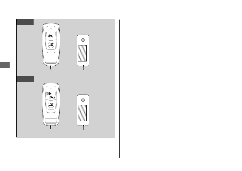
Keys
Information
150
Honda SMART Key ID tag
KO type
ED type
ID tagHonda SMART Key

Instruments, Controls, &
Other Features
Ignition Switch
Leaving the ignition switch in the (On) position
with the engine stopped will drain the battery.
Do not turn the ignition switch while riding.
Odometer
The display locks at 999,999 when the read-out
exceeds 999,999.
Tripmeter
The tripmeter returns to 0.0 when the read-out
exceeds 9,999.9.
Document Bag
The owner’s manual, registration, and insurance
information can be stored in the plastic
document bag located underside of the seat.
Instruments, Controls, & Other Features
Information
151

Caring for Your Vehicle
Frequent cleaning and polishing is important to
ensure the life of your Honda. A clean vehicle
makes it easier to spot potential problems.
In particular, seawater and salts used to prevent
ice on roads promote the formation of
corrosion. Always wash your vehicle thoroughly
after riding on coastal or treated roads.
Washing
Allow the engine, muffler, brakes, and other
high-temperature parts to cool before washing.
1.
Rinse your vehicle thoroughly using a low
pressure garden hose to remove loose dirt.
2.
If necessary, use a sponge or a soft towel
with mild cleaner to remove road grime.
u Clean the windscreen, headlight lens,
panels, and other plastic components
with extra care to avoid scratching them.
Avoid directing water into the air cleaner,
muffler, and electrical parts.
3.
Thoroughly rinse your vehicle with plenty of
clean water and dry with a soft, clean cloth.
4.
After the vehicle dries, lubricate any moving
parts.
u Make sure that no lubricant spills onto
the brakes or tyres. Brake discs, pads,
drum or shoes contaminated with oil will
suffer greatly reduced braking
effectiveness and can lead to a crash.
5.
Apply a coat of wax to prevent corrosion.
u
Avoid products that contain harsh
detergents or chemical solvents. These
can damage the metal, paint, and plastic
on your vehicle.
Keep the wax clear of the tyres and brakes.
u If your vehicle has any matte painted
parts, do not apply a coat of wax to the
matte painted surface.
Caring for Your Vehicle
Information
152

#
Washing Precautions
Follow these guidelines when washing:
● Do not use high-pressure washers:
u High-pressure water cleaners can
damage moving parts and electrical
parts, rendering them inoperable.
u Water in the air intake can be drawn into
the throttle body and/or enter the air
cleaner.
● Do not direct water at the muffler:
u Water in the muffler can prevent starting
and causes rust in the muffler.
● Dry the brakes:
u Water adversely affects braking
effectiveness. After washing, apply the
brakes intermittently at low speed to
help dry them.
● Do not direct water under the seat:
u Water in the under seat compartment
can damage your documents and other
belongings.
● Do not direct water at the air cleaner:
u Water in the air cleaner can prevent the
engine from starting.
● Do not direct water near the headlight:
u The headlight's inside lens may fog
temporarily after washing or while riding
in the rain. This does not impact the
headlight function.
However, if you see a large amount of
water or ice accumulated inside the
lens(es), have your vehicle inspected by
your dealer.
●
Do not use wax or polishing compounds on
mat painted surface:
u Use a soft cloth or sponge, plenty of
water, and a mild detergent to clean mat
painted surfaces. Dry with a soft clean
cloth.
Caring for Your Vehicle
Information
153
Continued

Aluminium Components
Aluminium will corrode from contact with dirt,
mud, or road salt. Clean aluminium parts
regularly and follow these guidelines to avoid
scratches:
● Do not use stiff brushes, steel wool, or
cleaners containing abrasives.
● Avoid riding over or scraping against curbs.
Panels
Follow these guidelines to prevent scratches
and blemishes:
● Wash gently using a soft sponge and plenty
of water.
● To remove stubborn stains, use diluted
detergent and rinse thoroughly with plenty
of water.
● Avoid getting petrol, brake fluid, or
detergents on the instruments, panels, or
headlight.
Caring for Your Vehicle
Information
154
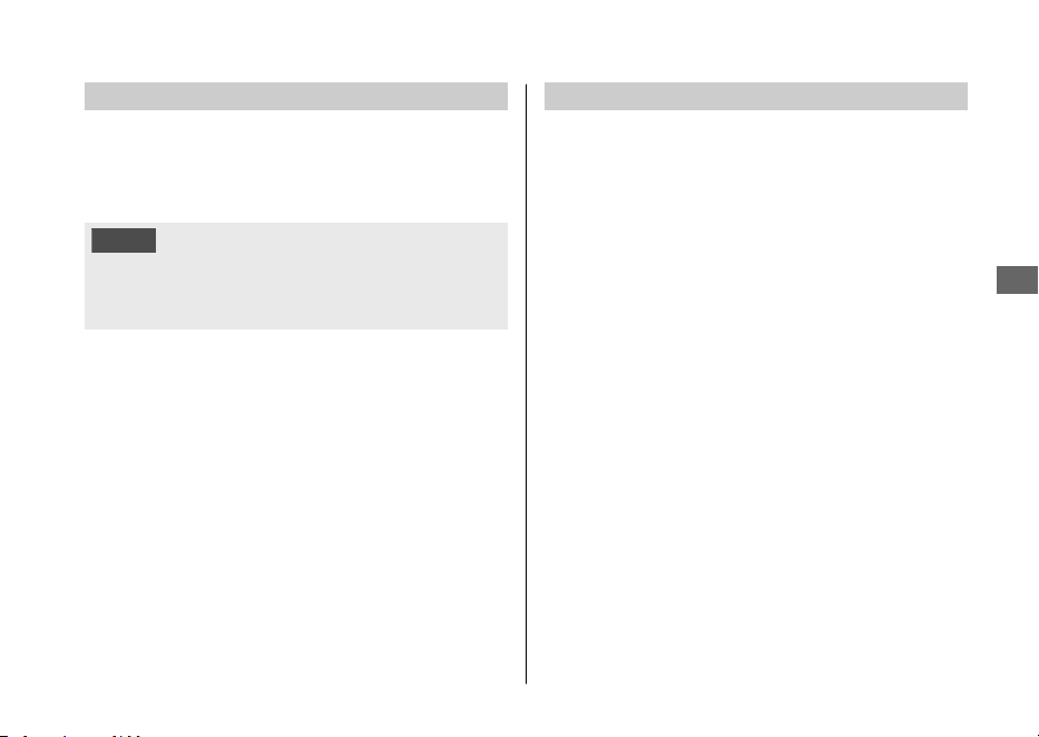
Windscreen
Using plenty of water, clean the windscreen with
a soft cloth or sponge. (Avoid using detergents
or any kind of chemical cleaner on the
windscreen.) Dry with a soft, clean cloth.
NOTICE
To avoid possible scratching or other damage,
use only water and a soft cloth or sponge to
clean the windscreen.
For a dirtier windscreen, use a diluted neutral
detergent with a sponge and plenty of water.
Make sure to wash off all the detergent.
(Detergent residue may cause windscreen
cracks.)
Replace the windscreen if scratches cannot be
removed and they obstruct clear vision.
Take care to keep battery electrolyte, brake
fluid, or other chemical solvents off the
windscreen and screen garnish. They will
damage the plastic.
Exhaust Pipe and Muffler
When the exhaust pipe and muffler are painted,
do not use a commercially available abrasive
kitchen cleaning compound. Use a neutral
detergent to clean the painted surface on the
exhaust pipe and muffler. If you are not sure if
your exhaust pipe and muffler are painted,
contact your dealer.
Caring for Your Vehicle
Information
155

Storing Your Vehicle
If you store your vehicle outdoors, you should
consider using a full-body cover.
If you won't be riding for an extended period,
follow these guidelines:
●
Wash your vehicle and wax all painted
surfaces (except matte painted surfaces).
Coat chrome pieces with rust-inhibiting oil.
●
Place your vehicle on its centre stand and
position a block so that both tyres are off
the ground.
● After rain, remove the body cover and allow
the vehicle to dry.
● Remove the battery (2 P. 103) to prevent
discharge. Fully charge the battery and then
place it in a shaded, well-ventilated area.
u
If you leave the battery in place,
disconnect the negative - terminal to
prevent discharge.
After removing your vehicle from storage,
inspect all maintenance items required by the
Maintenance Schedule.
Storing Your Vehicle
Information
156

Transporting Your Vehicle
If your vehicle needs to be transported, it
should be carried on a motorcycle trailer or a
flatbed truck or trailer that has a loading ramp
or lifting platform, and motorcycle tie-down
straps. Never try to tow your vehicle with a
wheel or wheels on the ground.
NOTICE
Towing your vehicle can cause serious damage
to the transmission.
Transporting Your Vehicle
Information
157

You & the Environment
Owning and riding a vehicle can be enjoyable,
but you must do your part to protect the
environment.
Choose Sensible Cleaners
Use a biodegradable detergent when you wash
your vehicle. Avoid aerosol spray cleaners that
contain chlorofluorocarbons (CFCs) which
damage the atmosphere's protective ozone
layer.
Recycle Wastes
Put oil and other toxic wastes in approved
containers and take them to a recycling centre.
Call your local or state office of public works or
environmental services to find a recycling centre
in your area, and to get instructions on how to
dispose of non-recyclable wastes. Do not place
used engine oil in the trash, or pour it down a
drain or on the ground. Used oil, petrol,
coolant, and cleaning solvents contain poisons
that can hurt refuse workers and contaminate
drinking water, lakes, rivers, and oceans.
You & the Environment
Information
158
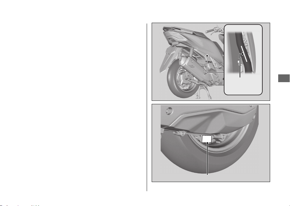
Serial Numbers
The frame and engine serial numbers uniquely
identify your vehicle and are required in order
to register your vehicle. They may also be
required when ordering replacement parts.
The frame number is stamped at the back on
the right side of the frame.
You can check it from below at the back on the
right side of the vehicle.
You should record these numbers and keep
them in a safe place.
Serial Numbers
Information
159
Frame
number
Engine number

Fuels Containing Alcohol
Some conventional fuels blended with alcohol
are available in some locales to help reduce
emissions to meet clean air standards. If you
plan to use blended fuel, check that it is
unleaded and meets the minimum octane
rating requirement.
The following fuel blends can be used in your
vehicle:
● Ethanol (ethyl alcohol) up to 10% by volume.
u Petrol containing ethanol may be
marketed under the name Gasohol.
The use of petrol containing more than 10%
ethanol may:
● Damage the painting of the fuel tank.
● Damage the rubber tubes of the fuel line.
● Cause corrosion of the fuel tank.
● Cause poor drivability.
NOTICE
Use of blended fuels containing higher than
approved percentages can damage metal,
rubber, plastic parts of your fuel system.
If you notice any undesirable operating
symptoms or performance problems, try a
different brand of petrol.
Fuels Containing Alcohol
Information
160

Catalytic Converter
This vehicle is equipped with a three-way
catalytic converter. The catalytic converter
contains precious metals that serve as catalysts
in high temperature chemical reactions that
convert hydrocarbons (HC), carbon monoxide
(CO), and oxides of nitrogen (NOx) in the
exhaust gasses into safe compounds.
A defective catalytic converter contributes to air
pollution and can impair your engine's
performance. A replacement unit must be an
original Honda part or equivalent.
Follow these guidelines to protect your vehicle's
catalytic converter.
● Always use unleaded petrol. Leaded petrol
will damage the catalytic converter.
● Keep the engine in good running condition.
● Have your vehicle serviced if your engine is
misfiring, backfiring, stalling, or otherwise
not running properly, stop riding and turn
off the engine.
Catalytic Converter
Information
161
Specifications
■ Main Components
Overall length 1,935 mm (76.2 in)
Overall width 740 mm (29.1 in)
Overall height 1,105 mm (43.5 in)
Wheelbase 1,315 mm (51.8 in)
Minimum ground
clearance
135 mm (5.3 in)
Caster angle 26º 30’
Trail
ED type 79 mm (3.1 in)
KO type 80 mm (3.1 in)
Curb weight 130 kg (287 lb)
Maximum weight
capacity
*1
ED type 180 kg (397 lb)
KO type 160 kg (353 lb)
Maximum luggage
weight
*2
13 kg (29 lb)
Centre compartment 10 kg (22 lb)
Front box 1.0 kg (2.2 lb)
Rear carrier 5 kg (11 lb)
Passenger capacity Rider and 1 passenger
Minimum turning radius 1.90 m (6.2 ft)
*1 : Including rider, passenger, all luggage, and accessories.
*2 : Includes the weight of the luggage and added accessories.
Displacement 125 cm
3
(7.6 cu-in)
Bore x stroke 53.5 x 55.5 mm (2.11 x 2.19 in)
Compression ratio 11.5:1
Fuel
Unleaded petrol
Recommended: 91 RON or higher
Fuel containing alcohol ETHANOL up to 10 % by volume
Tank capacity 8.1 L (2.14 US gal, 1.78 Imp gal)
Battery
ED type
YTZ8V
12 V-7.0 Ah (10 HR) / 7.4 Ah (20 HR)
KO type
GTZ8V
12 V-7.0 Ah (10 HR)
Primary reduction V-Matic (2.65:1-0.81:1)
Final reduction 10.352
Specifications
162
■ Service Data
Tyre size
Front
110/70-14M/C 50P
Rear
130/70-13M/C 63P
Tyre type Bias-ply, tubeless
Recommended
Tyres
ED type
Front MICHELIN CITY GRIP
Rear MICHELIN CITY GRIP
KO type
Front IRC SCT-006
Rear IRC SCT-007
Tyre category
of use
*1
Normal Permitted
Special Not Permitted
Snow Not Permitted
Moped Not Permitted
Tyre air
pressure
(Drivers only)
Front 200 kPa (2.00 kgf/cm
2
, 29 psi)
Rear 225 kPa (2.25 kgf/cm
2
, 33 psi)
Tyre air
pressure
(Driver and
passenger)
Front 200 kPa (2.00 kgf/cm
2
, 29 psi)
Rear 250 kPa (2.50 kgf/cm
2
, 36 psi)
Spark plug (standard) LMAR8L-9 (NGK)
Spark plug gap 0.8 - 0.9 mm (0.03 - 0.04 in)
Idle speed 1,700 ± 100 rpm
*1 : EU regulation
Recommended
engine oil
Honda 4-stroke motorcycle oil API Service
Classification SG or higher, excluding oils
marked as “Energy Conserving” or “Resource
Conserving, ”SAE 10W-30, JASO T 903 standard
MB
Engine oil
capacity
After draining
0.8 L (0.8 US qt, 0.7 Imp qt)
After draining
& cleaning
strainer screen
0.85 L (0.90 US qt, 0.75 Imp qt)
After
disassembly
0.9 L (1.0 US qt, 0.8 Imp qt)
Transmission
oil capacity
After draining 0.12 L (0.13 US qt, 0.11 Imp qt)
After
disassembly
0.14 L (0.15 US qt, 0.12 Imp qt)
Recommended
brake fluid
Honda DOT 3 or DOT 4 Brake Fluid
Cooling system
capacity
0.50 L (0.53 US qt, 0.44 Imp qt)
Recommended
coolant
Pro Honda HP Coolant
Specifications
Specifications
163
■ Bulbs
Headlight LED
Brakelights/Taillights LED
Front turn signal lights LED
Rear turn signal lights LED
License plate light LED
Position lights LED
■ Fuses
Main fuse 30 A
Other fuses
WW125A 15 A, 10 A, 7.5 A
WW125 10 A, 7.5 A
Specifications
Specifications
164

Index
A
ABS (Anti-lock Brake System) .............. 11, 128
ABS (Anti-lock Brake System) indicator..... 42
Accessories........................................................ 15
Average fuel mileage meter ......................... 28
B
Battery........................................................ 94, 103
Battery Charging Condition
indicator .................................................. 41, 127
Brakes
Brake Lever Freeplay....................................... 115
Fluid .................................................... 97, 110, 112
Pad Wear.................................................. 113, 114
Shoe Wear......................................................... 118
Braking ............................................................... 11
C
Catalytic Converter........................................ 161
Centre Compartment...................................... 84
Clock ................................................................... 27
Colour Label...................................................... 93
Compartment
Document Bag ................................................. 151
Owner’s Manual............................................... 151
Coolant............................................................. 108
D
Digital Clock Adjustment............................... 33
Display Setting ................................................. 31
Document Bag ......................................... 84, 151
E
Emergency
Emergency Key................................................. 147
Unlock the Seat ................................................ 137
Engine
Number.............................................................. 159
Electrical Trouble ........................................... 142
Environment ................................................... 158
F
Flooded Engine ................................................ 73
Frame Number ............................................... 159
Front Box ........................................................... 85
Index
165

Fuel
Gauge ................................................................... 27
Recommended................................................... 78
Remaining............................................................ 27
Tank Capacity ..................................................... 78
Fuses........................................................... 96, 143
G
Gasohol ............................................................ 160
H
Hazard Switch................................................... 44
Headlight Dimmer Switch ............................. 44
Helmet Holder.................................................. 83
High Beam Indicator....................................... 40
High Coolant Temperature Indicator ......... 40
Honda SMART Key........................................ 148
Honda SMART Key Indicator ........................ 41
Honda SMART Key System ........................... 47
Horn Button ...................................................... 44
I
Idling Stop Indicator....................................... 40
Idling Stop Switch ........................................... 44
Idling Stop System .......................................... 69
Ignition Cut-off System
Side Stand ......................................................... 119
Ignition Switch......................................... 45, 151
Image Labels ....................................................... 6
Indicators........................................................... 40
Instruments ....................................................... 26
K
Key
Emergency Key................................................. 147
Honda SMART .................................................... 47
L
Labels.................................................................... 6
Load Limits ........................................................ 16
Loading Guidelines.......................................... 16
M
Maintenance
Fundamentals ..................................................... 92
Importance .......................................................... 88
Safety .................................................................... 88
Schedule............................................................... 89
Index
166

Maximum Weight Limit......................... 16 , 162
Modifications.................................................... 15
O
Odometer.................................................. 28, 151
Oil
Engine.......................................................... 96, 106
OIL CHANGE indicator.................................... 29
Overheating .................................................... 126
P
Parking ............................................................... 12
Parts Location................................................... 20
Petrol.................................................... 14, 78, 162
PGM-FI (Programmed Fuel Injection)
Malfunction Indicator Lamp (MIL).... 40, 127
Protective Apparel........................................... 10
R
Rear Carrier ....................................................... 86
Recommended
Coolant................................................................. 98
Fuel........................................................................ 78
Oil .......................................................................... 96
Refuelling........................................................... 78
Removal
Battery ................................................................ 103
Battery Cover.................................................... 104
Front Lid............................................................. 105
Repair Kit ......................................................... 141
Riding Precautions .......................................... 11
S
Safety Precautions........................................... 10
Seat ..................................................................... 82
Serial Numbers............................................... 159
Side Stand ....................................................... 119
Side Stand Ignition Cut-off System.... 73, 119
Specifications.................................................. 162
Speedometer .................................................... 27
Start Button....................................................... 44
Starting the Engine ......................................... 73
Index
167

Storage
Centre Compartment........................................ 84
Equipment ........................................................... 82
Front Box.............................................................. 85
Owner’s Manual........................................ 84, 151
Rear Carrier ......................................................... 86
Tool Kit.................................................................. 84
Storing.............................................................. 156
Switches ............................................................. 44
T
Throttle ............................................................ 120
Tool ................................................................... 102
Torque Control................................................. 28
Torque Control indicator ............................... 42
Torque Control OFF indicator....................... 42
Transporting ................................................... 157
Tripmeter................................................... 28, 151
Troubleshooting ............................................ 124
Turn Signal Indicators .................................... 41
Turn Signal Switch........................................... 44
Tyres
Air Pressure ................................................ 99, 163
Puncture............................................................. 141
Replacing ............................................................. 99
V
V-BELT indicator .............................................. 30
W
Warning Indicator On................................... 127
Washing Your Scooter.................................. 152
Weight Limit ..................................................... 16
Index
168