Loading ...
Loading ...
Loading ...
Controls & Operation
4
7
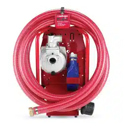
Primer Filler Plug
Discharge Port (2” NPT)
Suction Port (2” NPT)
Water Drain Plug
Rear Handle
Suction Hose Storage
Discharge Hose Storage
Suction Hose with Strainer
Discharge Hose
Suction Hose
Tie Down Strap
Figure 4-1
WARNING! Read and follow all safety rules and instructions in this manual, including the
entire Controls & Operation section, before attempting to operate this machine. Failure to
comply with all safety rules and instructions may result in personal injury.
WARNING! This attachment weighs
61 lb. and requires two people to lift it.
Rear Handle
The rear handle should be used to move the water
pump around when NOT attached to the FLEX™
Power Base.
Discharge Port (2” NPT)
Connects discharge hose to the pump. Can be
rotated 90° left or right to adjust the angle of water
discharge.
Suction Port (2” NPT)
Connects suction hose to the pump.
Primer Filler Plug
Remove plug to fill pump chamber with water to
prime the water pump for each use.
Water Drain Plug
Remove plug to drain water and sediment from
inside the pump after use.
Suction Hose Storage
Used for storing the suction hose with strainer
when not in use.
Discharge Hose Storage
The bracket located next to the pump allows for
safe and secure storage of the discharge hose.
Suction Hose with Strainer
Rigid hose construction with threaded end for
connection to Suction Port on pump, with a
strainer end for submersion into a water source.
Discharge Hose
Flexible lay flat hose construction with threaded
end for connection to Discharge Port on pump.
Suction Hose Tie Down Strap
Used to help secure the suction hose with strainer.
Read the entire Operator’s Manual
before you attempt to operate your
new water pump.
Starting and Stopping the Engine
Start and stop the engine on the FLEX™ Power
Base in accordance with the Operator’s Manual
included with that machine.
WARNING! If leaving this equipment
unattended turn the engine OFF and
remove the ignition key.
Connecting to the FLEX™ Power Base
NOTE: All references to the left or right side are from
the operator’s position. Any exceptions will be noted.
1. Roll the FLEX™ Power Base over to the water
pump attachment with the kickstand UP.
See Figure 4-2.
Figure 4-2
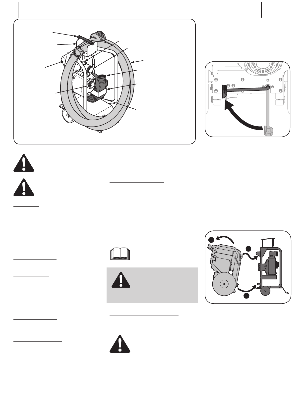
2. Roll the FLEX™ Power Base forward and tip it
up, engaging the top part of the water pump
attachment with the handle mount provided
on the FLEX™ Power Base (1 of Figure 4-3).
3. Tip the FLEX™ Power Base backwards to
engage the two bottom connection points
(2 and 3 of Figure 4-3).
Note: The operator will be able to hear the
lower mounts engage and lock (latching
sound) when coupled properly. To test if
coupled properly, lift up on the handles. If
the unit comes apart, the connection was
not made. Ensure that the kickstand is still
in the UP position, and swiftly tip the FLEX™
Power Base backward with the top mount
engaged.
1
3
2
Figure 4-3
Disconnecting from the FLEX™ Power Base
1. The kickstand acts only as a locking device
for the attachment to the FLEX™ Power Base.
The only time the operator would need
to deploy the kickstand once connected
to an attachment would be in the case of
uncoupling the FLEX™ Power Base from the
attachment.
CAUTION! When the FLEX™ Water
Pump attachment is attached to
the FLEX™ Power Base, the engine
should be started after the water
pump has been primed. We do not
recommend running the pump dry.
Loading ...
Loading ...
Loading ...