
FC600 FAN COIL THERMOSTAT- FULL USER MANUAL

2 Fan Coil FC600 Instructions Manual
Table of contents
1. Introduction ..................................................................................................................................................................4
1.1. Product Compliance ............................................................................................................................................... 4
1.2. Safety information ....................................................................................................................................................4
1.3. Product Overview .....................................................................................................................................................4
2. Operation Manual (Oine Mode) .............................................................................................................. 5
2.1. Principles of Operation ........................................................................................................................................... 5
2.2. Key Functions ............................................................................................................................................................... 5
2.3. LCD Icon Description ...............................................................................................................................................6
2.4. Power Up .........................................................................................................................................................................8
2.5. Temperature Setpoint .............................................................................................................................................9
2.6. Fan control ................................................................................................................................................................... 10
2.7. Operation Mode Selection ................................................................................................................................ 11
2.8. Other Mode Button Functions ...................................................................................................................... 14
2.8.1. Setting date and time ........................................................................................................................ 15
2.8.2. Setting Schedules ................................................................................................................................. 16
2.8.3. Offset Function ....................................................................................................................................... 19
2.9. Other Functions ...................................................................................................................................................... 19
2.9.1. Frost Protection ...................................................................................................................................... 19
2.9.2. Key Lock Function ................................................................................................................................ 20
2.9.3. Service Filter Reminder ...................................................................................................................... 20
2.9.4. Error Codes .............................................................................................................................................. 20
2.10. STANDBY Mode ..................................................................................................................................................... 21
3. Operation Manual (Online Mode) ........................................................................................................... 22
3.1. Quick Overview ........................................................................................................................................................ 22
3.2. App screen Icon Description ........................................................................................................................... 23
3.3. Device name change ............................................................................................................................................ 24
3.4. Temperature Setpoint .......................................................................................................................................... 24
3.5. Heat/Cool selection ............................................................................................................................................... 25
3.6. Work Status ................................................................................................................................................................. 26
3.6.1. Follow Schedule .................................................................................................................................... 26
3.6.2. Permanent hold ..................................................................................................................................... 26
3.6.3. Eco Mode .............................................................................................................................................. 27
3.6.4. STANDBY Mode ..................................................................................................................................... 28
3.7. Setting a schedule for the thermostat ....................................................................................................... 29
3.8. Fan Control .................................................................................................................................................................. 31
3.9. Key lock function ..................................................................................................................................................... 31
3.10. Occupancy Sensor ............................................................................................................................................... 32
3.11. Window Association Function ..................................................................................................................... 32
3.12. Identification Function ...................................................................................................................................... 33
3.13. Pin / Unpin thermostat to the dashboard ............................................................................................ 33
3.14. Service Settings ..................................................................................................................................................... 34
3.15. Using / Adding OneTouch .............................................................................................................................. 35

3 Fan Coil FC600 Instructions Manual
4. Installer Manual ..................................................................................................................................................... 36
4.1. Box Contents .............................................................................................................................................................. 36
4.2. Proper positioning of the thermostat ........................................................................................................ 36
4.3. Idea diagrams ............................................................................................................................................................ 37
4.4. Wiring options ........................................................................................................................................................... 40
4.5. Terminals explanation .......................................................................................................................................... 41
4.6. Wall Mounting ........................................................................................................................................................... 43
4.7. Online Mode (with internet connection .................................................................................................. 45
4.8. Installer Parameters ................................................................................................................................................ 49
4.8.1. In Offline Mode (with no Internet connection) ................................................................. 49
4.8.2. Switching from non-programmable to programmable thermostat .................... 49
4.8.3. In Online Mode (via App) ................................................................................................................. 50
4.9. Full Parameter List ................................................................................................................................................... 50
4.10. Fan and valve operation (V1) including pipe sensor in a 2-pipe system with the use
of "d24" and "d25" parameters ................................................................................................................................ 56
4.10.1. Fan operation in heating and cooling mode ................................................................... 56
4.10.2. Fan operation in cooling mode ................................................................................................ 57
4.10.3. Fan operation in heating mode ................................................................................................ 57
4.11. Switching from offline to online mode .................................................................................................. 58
4.12. Reset Function ....................................................................................................................................................... 60
4.12.1. In Local Mode (without Internet connection) ................................................................. 60
4.12.2. Via App .............................................................................................................................................. 60
4.13. Cleaning and Maintenance ............................................................................................................................ 61
4.14. Technical Specification ...................................................................................................................................... 61
4.15. Warranty ..................................................................................................................................................................... 62

4 Fan Coil FC600 Instructions Manual
Use in accordance with the regulations. Indoor use only. Keep your equipment completely dry. Disconnect
your equipment before cleaning it with a dry towel.
This product complies with the essential requirements and other relevant provisions of Directives 2014/30/EU,
2014/35/EU, 2014/53/EU and 2011/65/EU. The full text of the EU Declaration of Conformity is available at the
following Internet address: www.saluslegal.com
The Fan Coil thermostat (FC600) is a complex device that can help you control your room temperature and fan
speed in a large number of configurations. It can be connected to a 2 or 4 pipe system and can be associated
with multiple sensors (occupancy sensors, window sensors, pipe sensors), increasing by that the quality and
speed of the temperature management in your home, office, hotel etc. It can be used with a various number of
different devices such as trench heaters,central heating boilers, electrical heaters and many more.
The complex structure of the device lets you to set independent schedules on a weekly or daily basis, depending
on your preferences and needs. It has multiple work configuration possibilities and can be controlled in both
off-line and on-line modes. Besides that, it can work in Eco Mode, ensuring a economy of resources and money.
Feature List
• Control of 2/4 pipe fan coils
• Multiple configurations
• Large LCD
• Maintain room temperature via built in temperature sensor or external room temperature/return air
temperature sensor
• Programming options: 5+2 (5 days same+2days same); Individual day every week; All 7 days same
• ECO mode
• Fan speed Hi/Mi/Lo control ( automatic or manual )
• Advanced fan control functions ( fan start/stop, delay, fan continuously running in manual mode, or
depending on heating/cooling demand)
• Auto Frost protection
• Configurable inputs (occupancy sensor or temperature)
• Installer settings
• Span or TPI temperature control algorithm
• Local or remote control by SmartHome App
• Wireless software update by UG600
• Dirty filter notification
• User settings are saved and restored after power break
• Button lock function
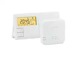
The Fan Coil can be used either online or offline. The thermostat can be paired online using UGE600 Universal
Gateway (purchased separately), being compatible with the Smart Home App and communicating with other
Smart Home devices like the window/door sensors, smart plugs, smart buttons. Also, you can use the Fan Coil
without the App. It can operate as a stand alone device.
1. Introduction
1.1. Product Compliance
1.2. Safety information
1.3. Product Overview
5 Fan Coil FC600 Instructions Manual
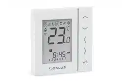
2. Operation Manual (Oine Mode)
The FC600 is designed for temperature control
in rooms equipped with heating and cooling
fain coils, water heaters, trench heaters. It
can control 2 valves (in 2 pipes the V1 input
controls heating and cooling, in 4 pipes V1
controls heating and V2 controls cooling).
FC600 can also control the FAN speed in
3 levels: low, medium or high, in order to
maintain the room temperature.
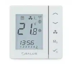
2.2. Key Functions
2.1. Principles of Operation
Key Function
Increase
Decrease
Fan Speed Low, Medium, High, Auto, Off
Mode button*
Short press Long press (2 sec)
Digital
Heat/Cool/Eco
selection
Offset, Time
Programmable
Permanent override
AUTO Heat/Cool/Eco
selection
Programming schedule Offset
Time & Date
* The function of the Mode button depends on the Fan Coil configuration
Short press: Confirm function
Long press (3 sec): Activate/deactivate STANDBY mode
6 Fan Coil FC600 Instructions Manual
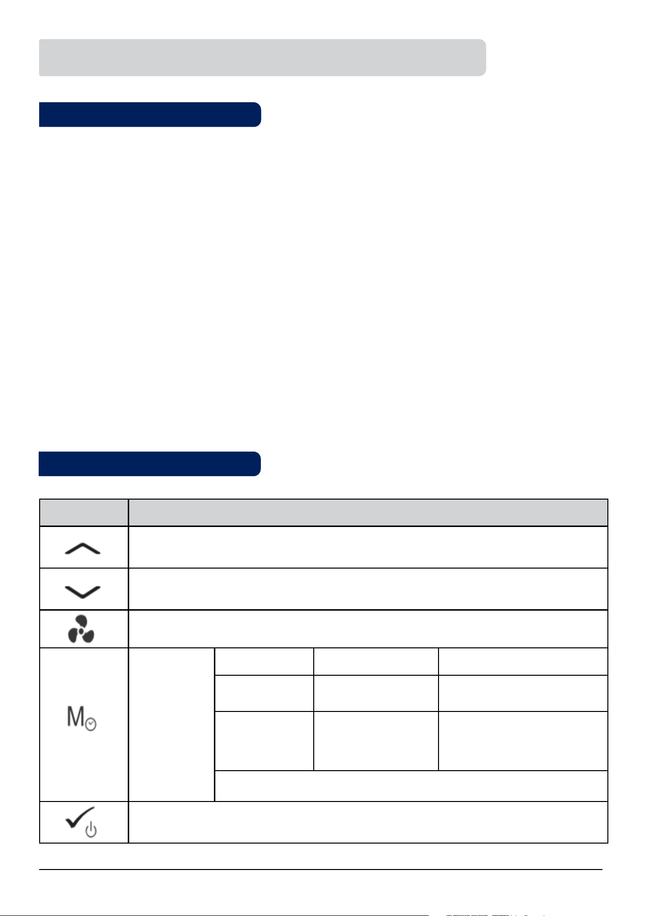
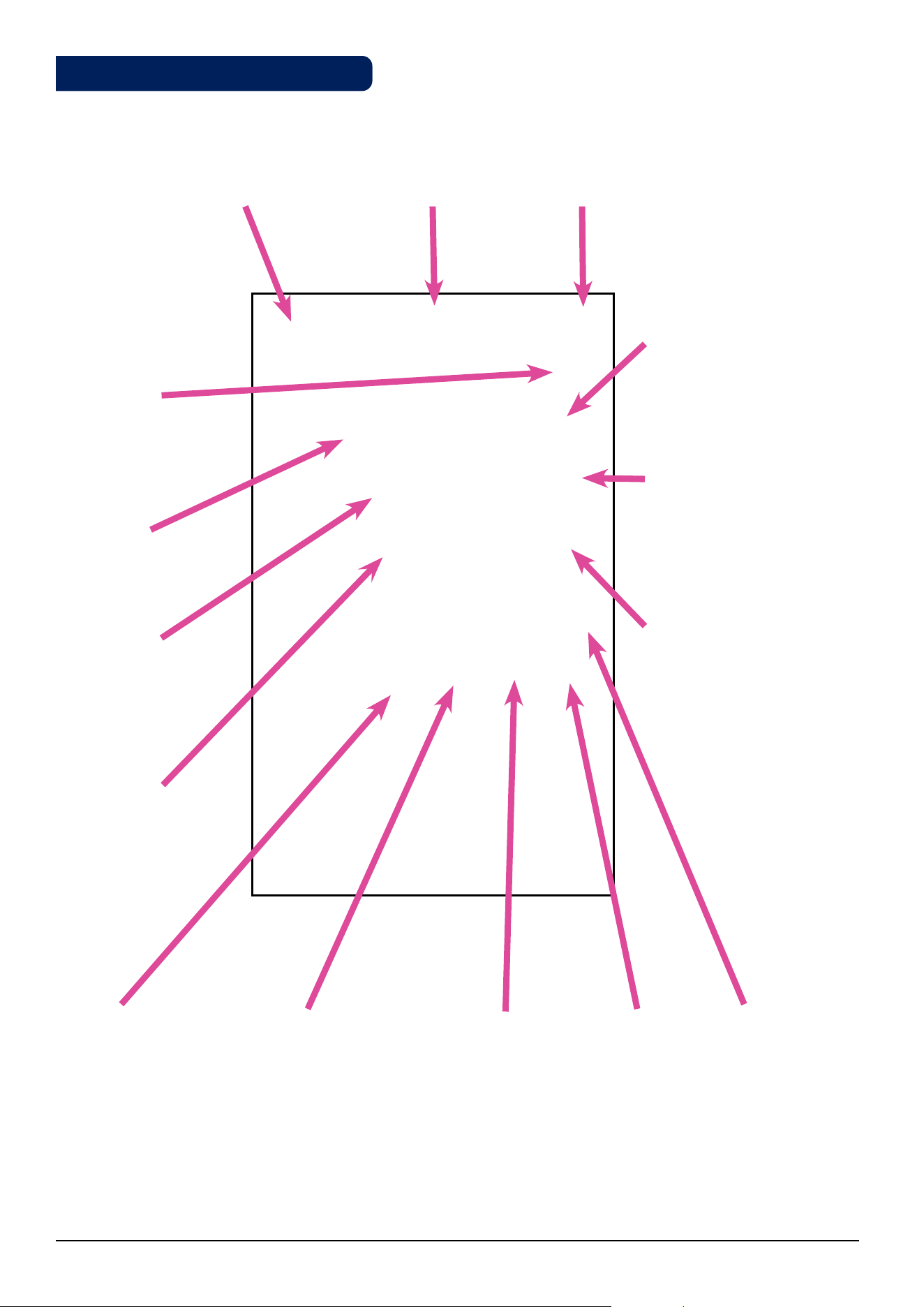
1 2 3 4 5 6
13
1718
16 15 14
725
24
23
22
21
20
19
12
10
11
9
8
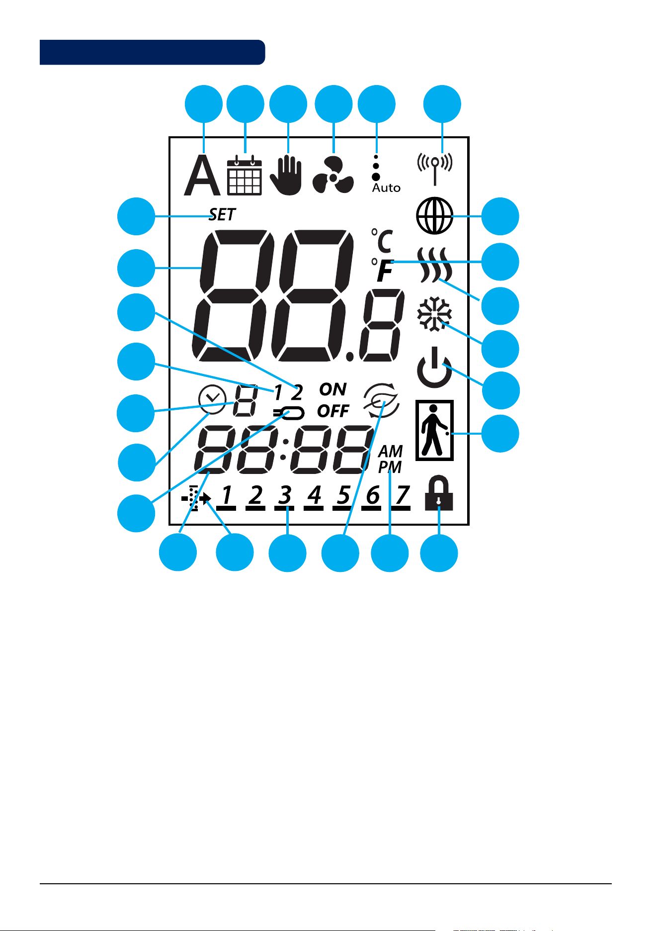
1. Auto heat/cool selection
2. Schedule icon
3. Permanent/temporary override
4. Fan icon
5. Fan speed (low, medium, high, Auto, OFF)
6. Wireless communication icon
7. Glob icon
8. Temperature unit
9. Heating Mode ON
10. Cooling Mode ON
11. STANDBY mode
12. Occupancy/vacancy sensor
13. Lock function
14. AM/PM
15. Eco Mode
16. Day Indicator
17. Filter icon
18. Current time
19. Sensor indicators
20. Timer icon
21. Program number
22. S1/COM Sensor indicators
23. S2/COM Sensor indicators
24. Room/set point temperature
25. Set point temperature indicator
2.3. LCD Icon Description
7 Fan Coil FC600 Instructions Manual
M
M
M
1. Auto heat/cool selection
This icon is visible when the thermostat is running in auto heat/
cool changeover.
14. AM/PM
Appears when you have 12 hours clock format.
2. Schedule icon
This icon is visible when the thermostat is programmable and is
following the schedule.
15. Eco Mode
This icon is visible when the thermostat runs in Eco Mode.
3. Permanent/temporary override
This icon is visible always when the thermostat is digital (non-
programmable) or when permanent override is enabled. When
temporary override is enabled, the icon will appear next to the
schedule icon.
16. Current day of the program
The current day of the program is underlined.
4. Fan icon
This icon is animating in sequence when the fan is
running.
17. Clear lter reminder
This icon is visible when the filters have to be replaced.
5. Fan speed (low, medium, high, Auto, OFF)
This icon shows fan speed and status.
18. Current time
Time Display.
6. Wireless communication icon
This icon appears when the thermostat is connected
to the Universal Gateway.
19. Sensor indicators
This icon is visible when a sensor is connected to S1/Com or S2/
COM terminals.
7. Glob icon
This icon is appears when the thermostat is
connected to the Universal Gateway and App via
Internet.
20. Timer icon
Icon appears during programming schedules,
indicates start time for a program.
8. Temperature unit
⁰C or F
21. Program number
Shows the program number when thermostat
follows schedule.
9. Heating Mode ON
This icon indicates heating mode. Animating when
calling for heat.
22. S1/COM Sensor indicators
Shows a sensor is connected to the S1/COM
terminal.
10. Cooling Mode On
This icon indicates cooling mode. Animating when
calling for cooling.
23. S1/COM Sensor indicators
Shows a sensor is connected to the S2/COM
terminal.
11. STANDBY mode
This icon indicates the thermostat is in STANDBY
Mode or Frost Protection.
24. Room/set point temperature
Indicates current room temperature, setpoint
temperature etc.
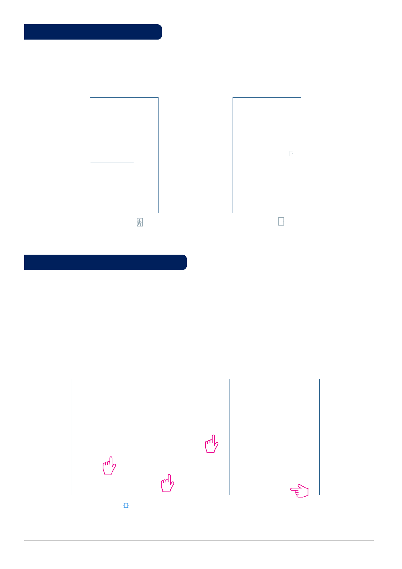
12. Occupancy/vacancy sensor
Man in door when presence detected , empty
door when not.
25. Set point temperature indicator
Icon appears when a new setpoint temperature is
being set.
13. Lock function
This icon indicates the keys of the device are locked.
M
M
low medium
OFF
high
M
M
M
M
8 Fan Coil FC600 Instructions Manual
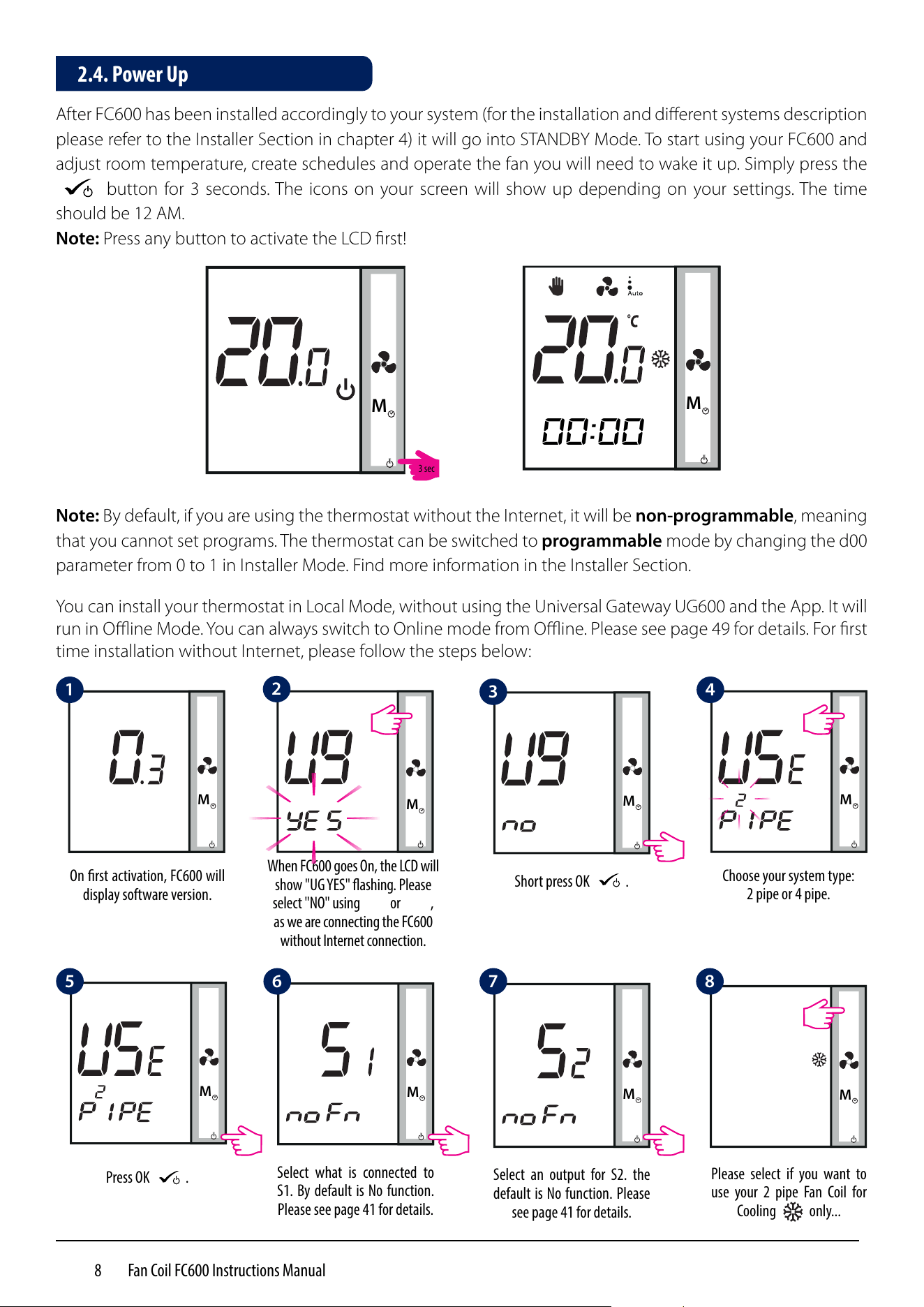
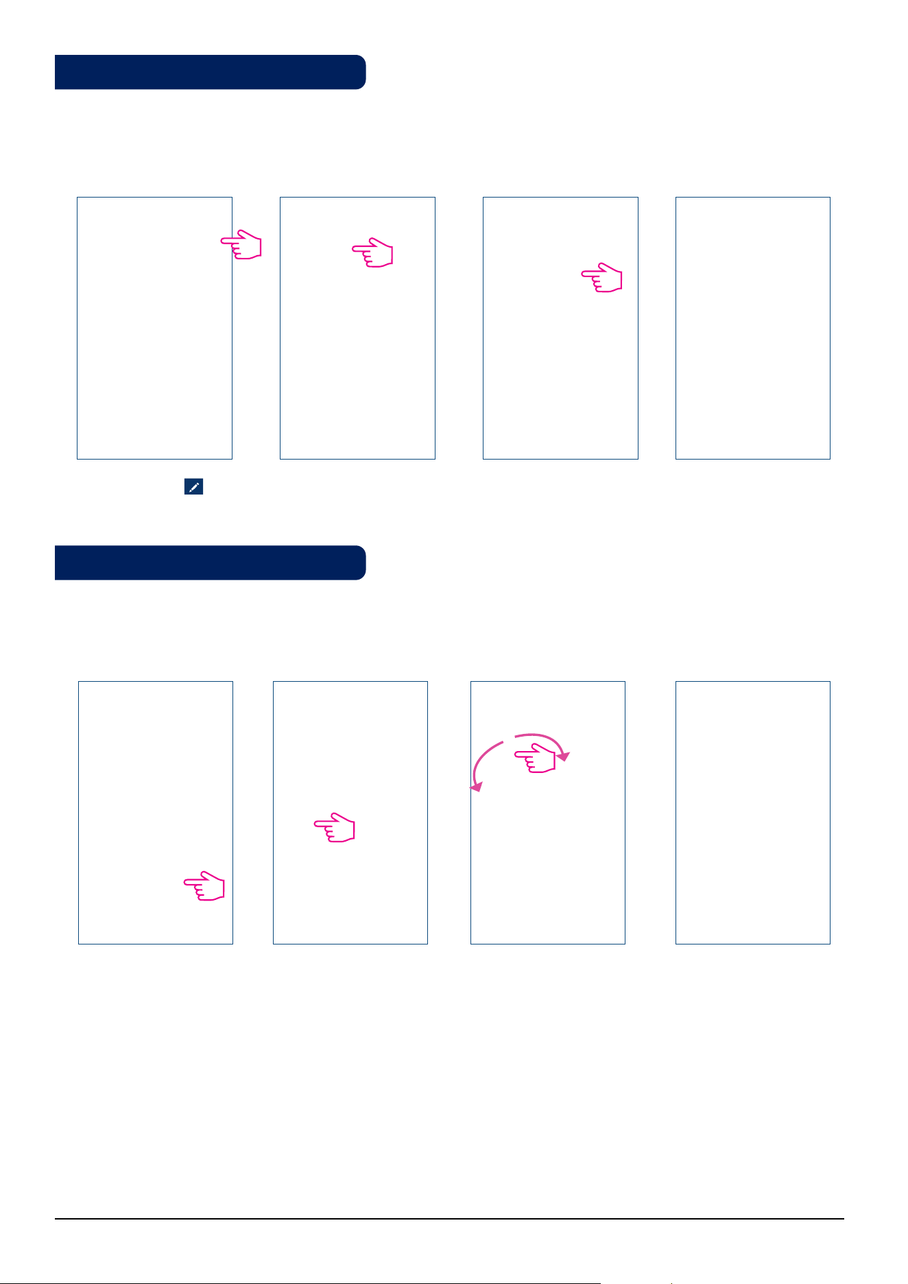
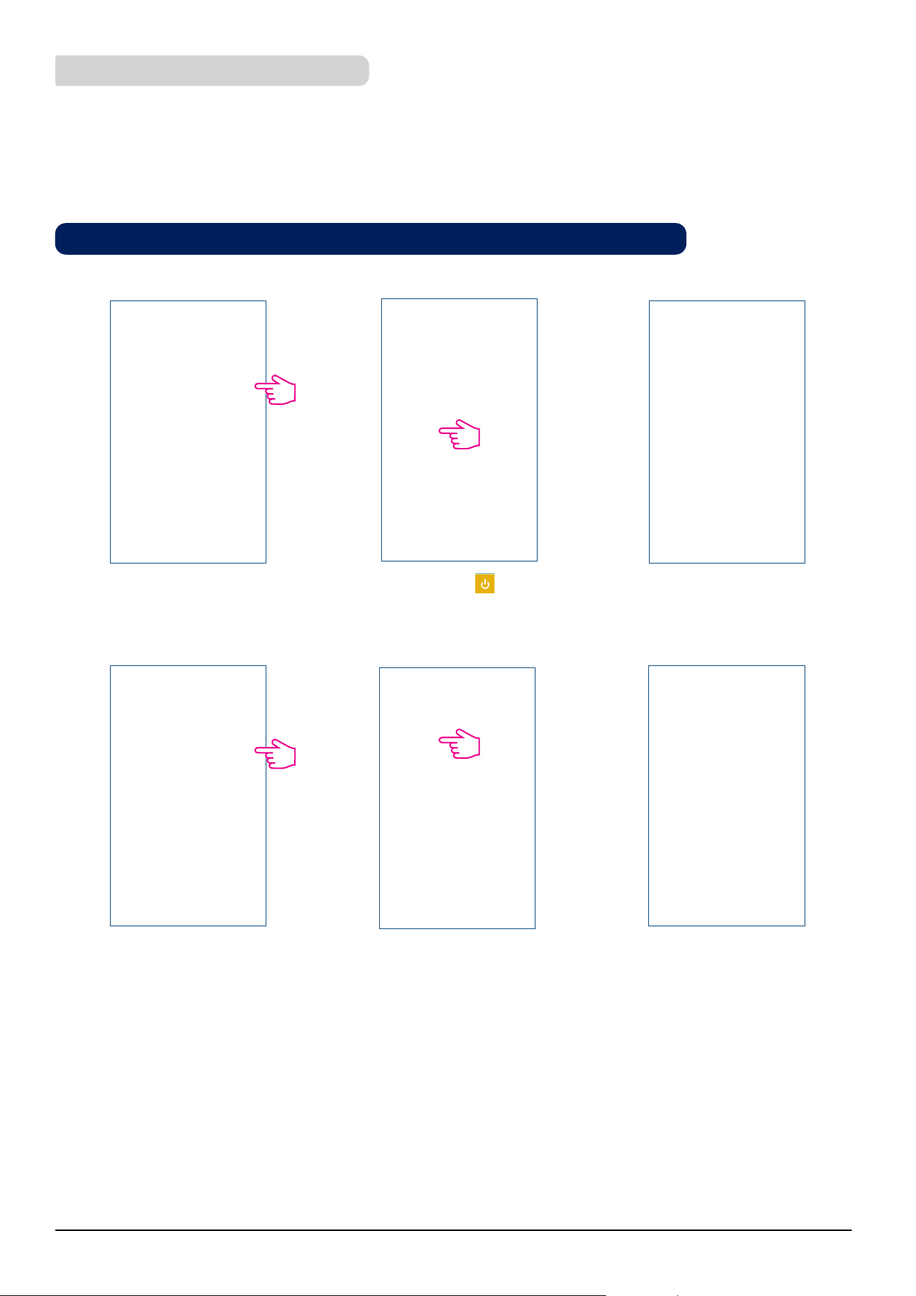
After FC600 has been installed accordingly to your system (for the installation and different systems description
please refer to the Installer Section in chapter 4) it will go into STANDBY Mode. To start using your FC600 and
adjust room temperature, create schedules and operate the fan you will need to wake it up. Simply press the
M
button for 3 seconds. The icons on your screen will show up depending on your settings. The time
should be 12 AM.
Note: Press any button to activate the LCD first!
M
M
Note: By default, if you are using the thermostat without the Internet, it will be non-programmable, meaning
that you cannot set programs. The thermostat can be switched to programmable mode by changing the d00
parameter from 0 to 1 in Installer Mode. Find more information in the Installer Section.
00:00
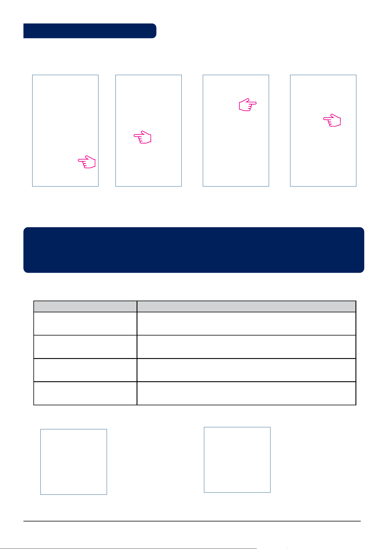
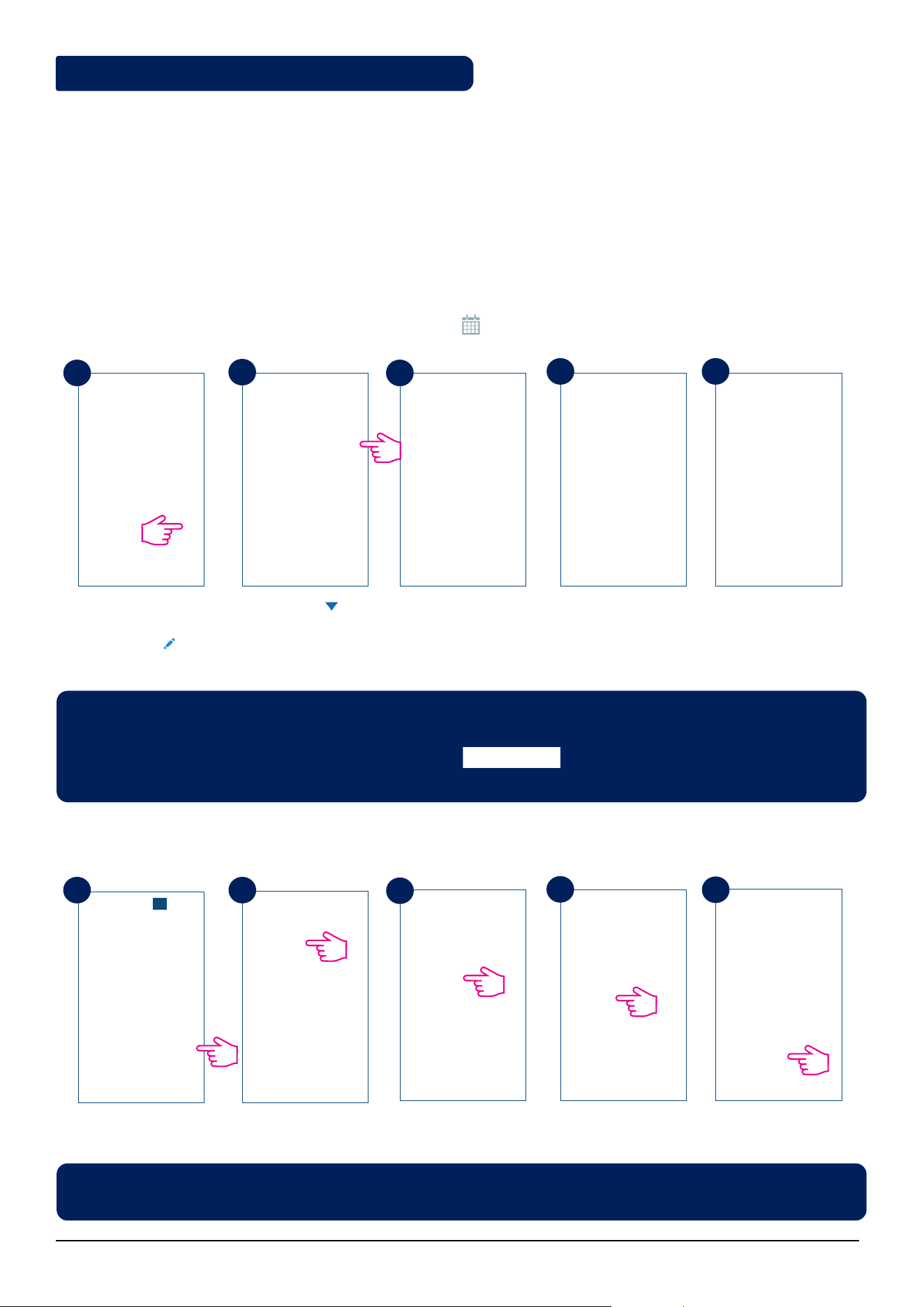
You can install your thermostat in Local Mode, without using the Universal Gateway UG600 and the App. It will
run in Offline Mode. You can always switch to Online mode from Offline. Please see page 49 for details. For first
time installation without Internet, please follow the steps below:
M
M
M
M
On rst activation, FC600 will
display software version.
When FC600 goes On, the LCD will
show "UG YES" ashing. Please
select "NO" using
M
or
M
,
as we are connecting the FC600
without Internet connection.
Choose your system type:
2 pipe or 4 pipe.
Short press OK
M
.
M
M
Select what is connected to
S1. By default is No function.
Please see page 41 for details.
Press OK
M
.
M
Select an output for S2. the
default is No function. Please
see page 41 for details.
M
Please select if you want to
use your 2 pipe Fan Coil for
Cooling only...
2.4. Power Up
1
2
3
4
5 6 7 8
3 sec
9 Fan Coil FC600 Instructions Manual
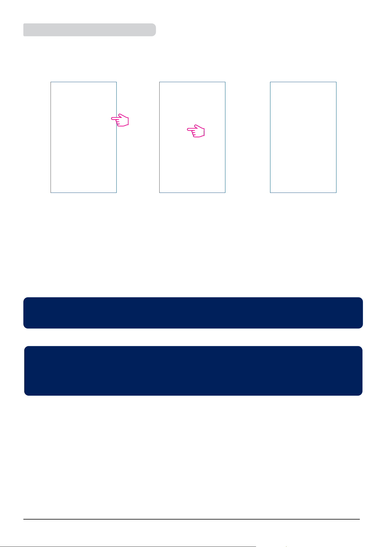
M
M
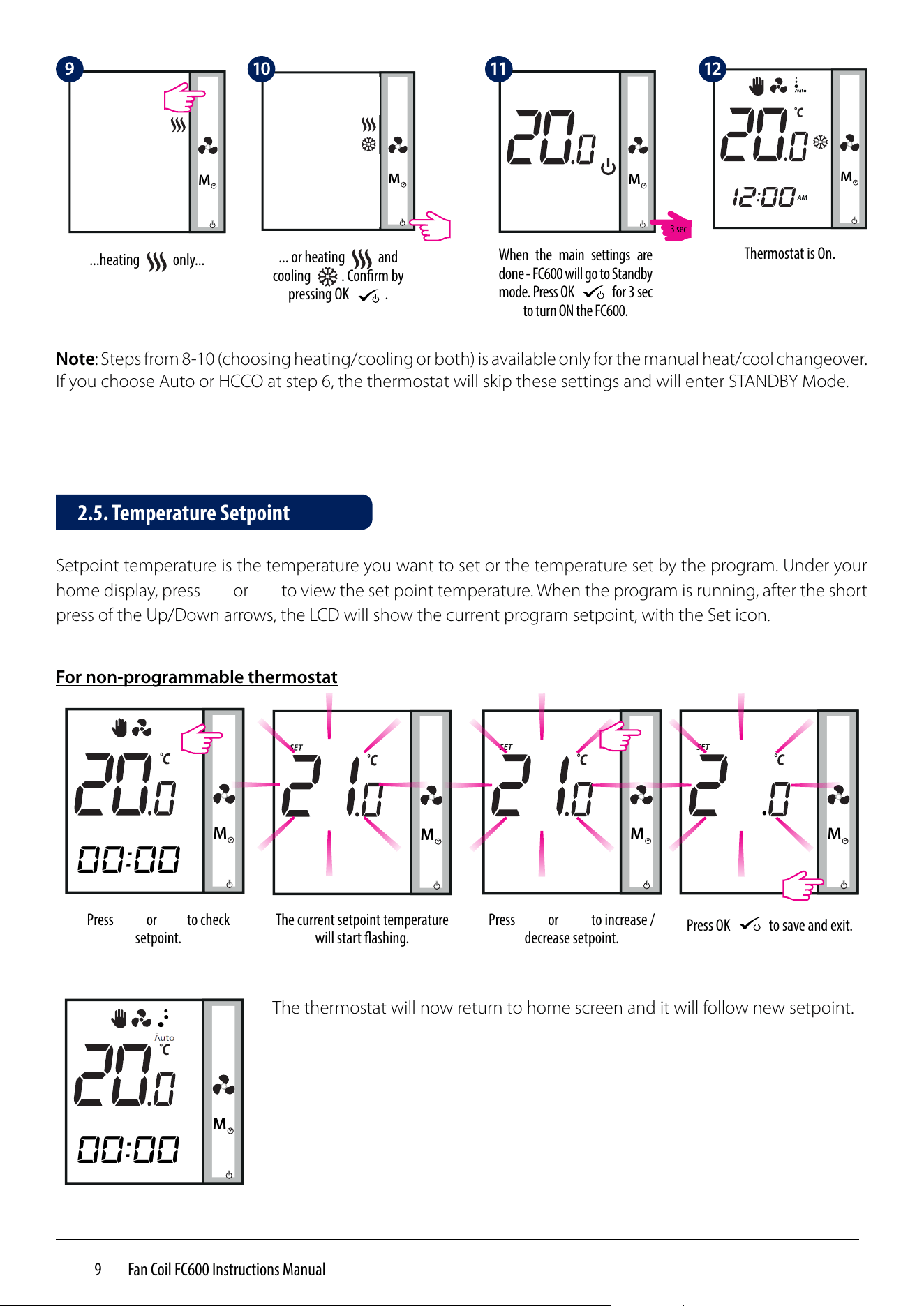
Press
M
or
M
to check
setpoint.
The current setpoint temperature
will start ashing.
Setpoint temperature is the temperature you want to set or the temperature set by the program. Under your
home display, press
M
or
M
to view the set point temperature. When the program is running, after the short
press of the Up/Down arrows, the LCD will show the current program setpoint, with the Set icon.
M
Press
M
or
M
to increase /
decrease setpoint.
M
Press OK
M
to save and exit.
For non-programmable thermostat
M
The thermostat will now return to home screen and it will follow new setpoint.
2.5. Temperature Setpoint
00:00
00:00
.
M
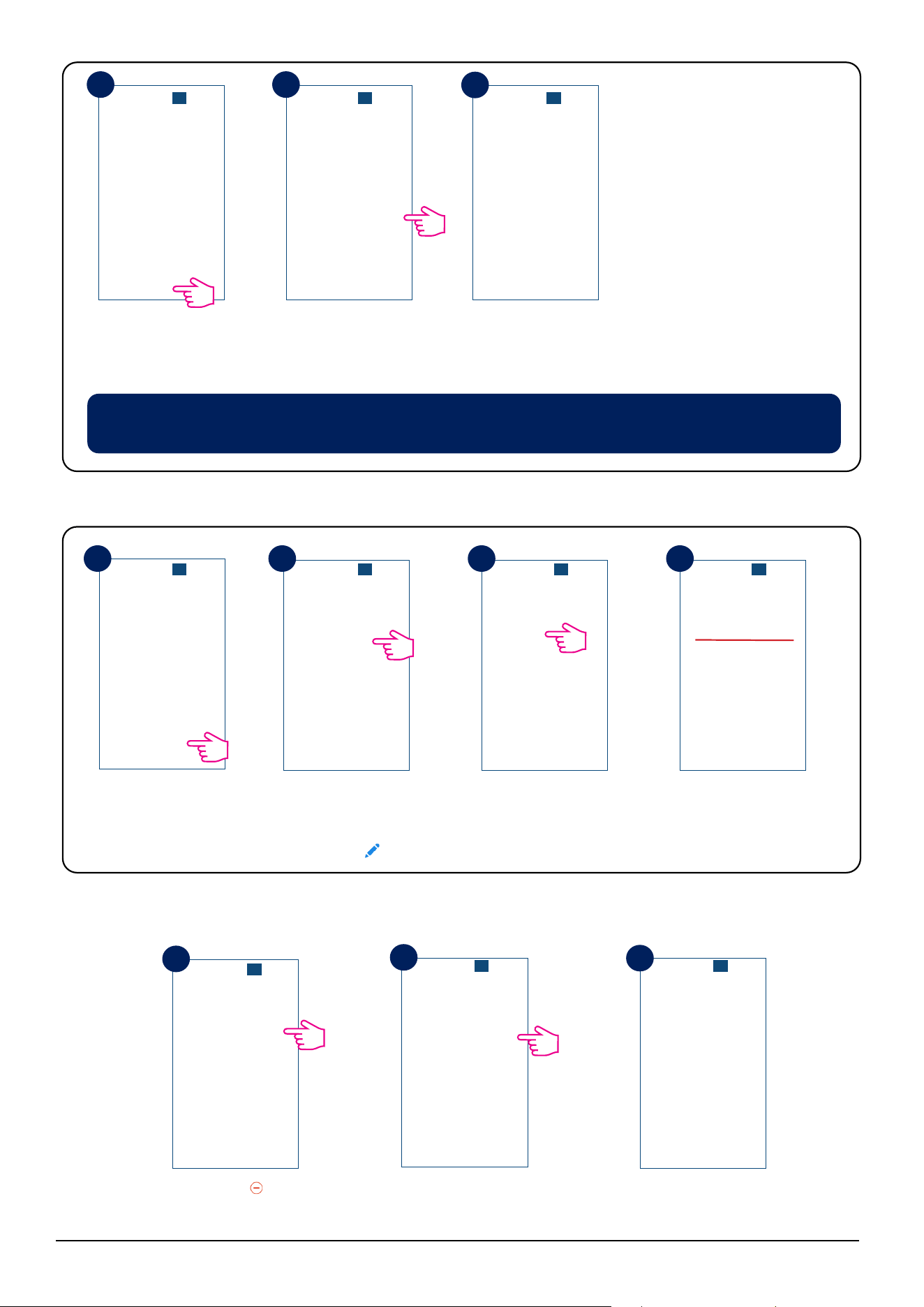
When the main settings are
done - FC600 will go to Standby
mode. Press OK
M
for 3 sec
to turn ON the FC600.
M
...heating only...
M
... or heating and
cooling . Conrm by
pressing OK
M
.
M
Thermostat is On.
Note: Steps from 8-10 (choosing heating/cooling or both) is available only for the manual heat/cool changeover.
If you choose Auto or HCCO at step 6, the thermostat will skip these settings and will enter STANDBY Mode.
M
9 10 11 12
3 sec
10 Fan Coil FC600 Instructions Manual
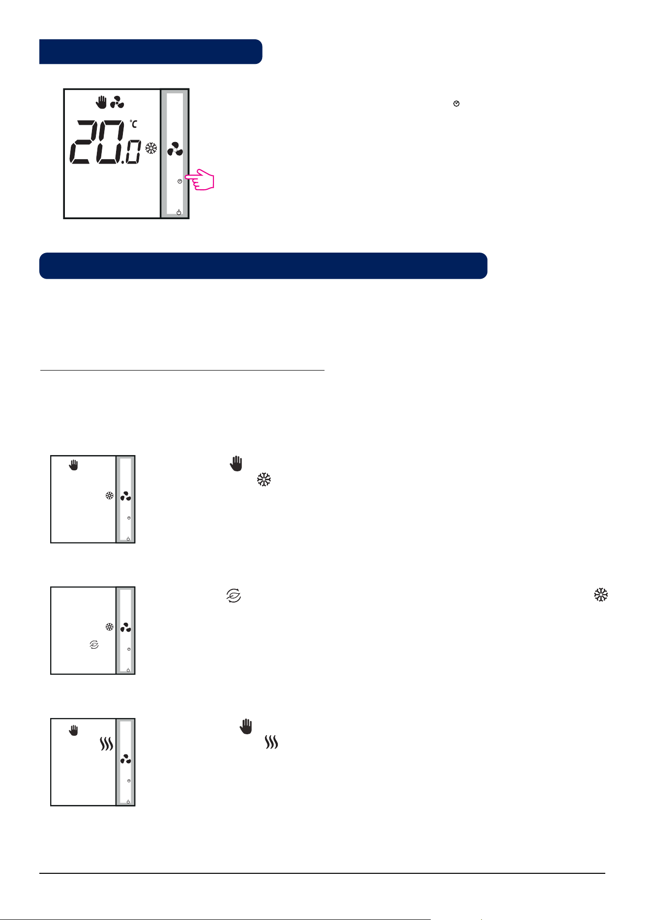
You can use the Fan Button to adjust the fan speed.
M
Press to select fan speed
Animation Meaning
Fan is not active
When the fan is running, the fan icon is animated
Fan speed: Low, Medium, High
Fan speed on Auto / Off. When fan is Off all dots
and Auto icon disappears
By default, the fan is on only when the Fan Coil calls for heating or cooling.
2.6. Fan control
00:00
M
M
M
M
M
M
M
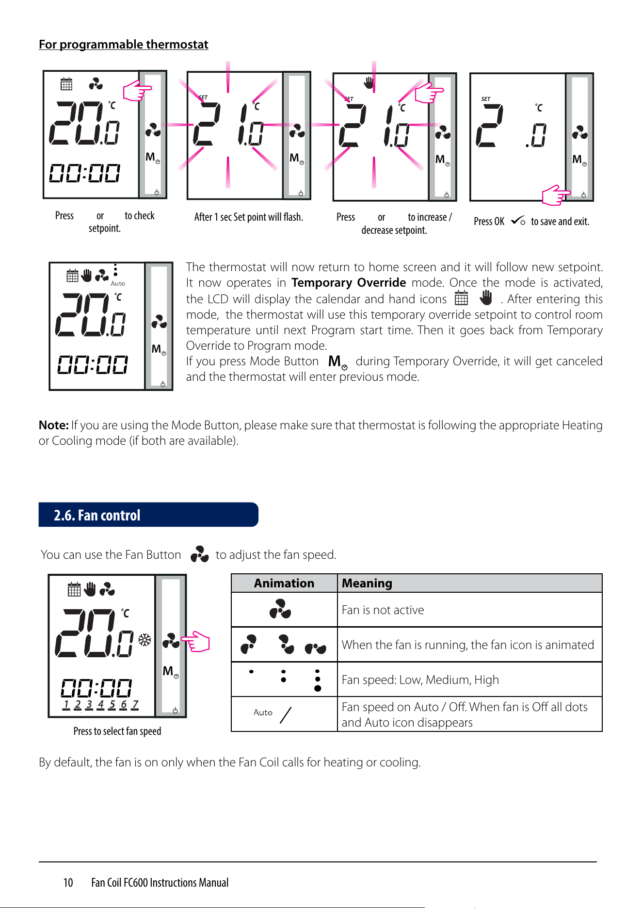
Press
M
or
M
to check
setpoint.
After 1 sec Set point will ash.
M
Press
M
or
M
to increase /
decrease setpoint.
M
Press OK
M
to save and exit.
For programmable thermostat
M
The thermostat will now return to home screen and it will follow new setpoint.
It now operates in Temporary Override mode. Once the mode is activated,
the LCD will display the calendar and hand icons . After entering this
mode, the thermostat will use this temporary override setpoint to control room
temperature until next Program start time. Then it goes back from Temporary
Override to Program mode.
If you press Mode Button
M
during Temporary Override, it will get canceled
and the thermostat will enter previous mode.
Note: If you are using the Mode Button, please make sure that thermostat is following the appropriate Heating
or Cooling mode (if both are available).
00:00
00:00
.
11 Fan Coil FC600 Instructions Manual
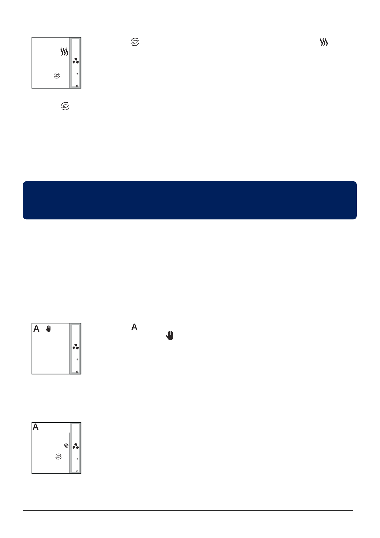
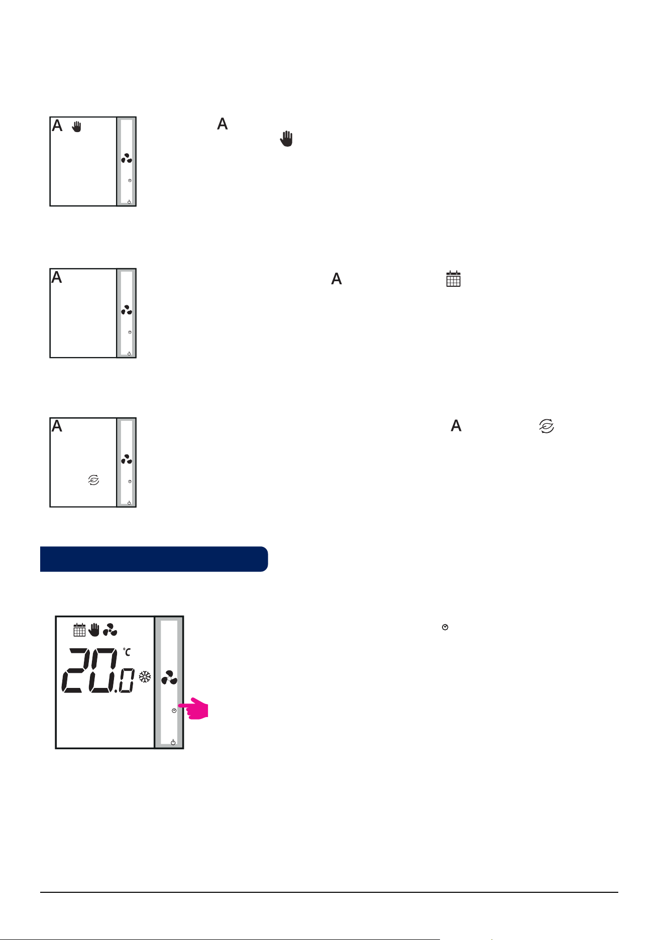
The Hand icon indicates that the thermostat is in permanent override (manual
mode). The heat icon
M
indicates that the thermostat is in Heating Mode. You can set a
temperature higher than the current temperature and the Fan Coil will maintain it until
you set a new setpoint.
3.
M
M
Modes for non-programmable (digital) thermostat
The Hand icon indicates that the thermostat is in permanent override (manual mode).
The snowflake icon indicates that the thermostat is in Cooling Mode. You can set a
temperature lower than the current temperature and the Fan Coil will maintain it until
you set a new setpoint.
M
If you have Manual Heat/Cool selection, these are the 4 possible combinations you can have by short
pressing the Mode Button:
M
M
The Leaf icon indicates that the thermostat is in Eco Mode. The snowflake icon
indicates that the thermostat is in Cooling Mode. When in Eco Mode, the thermostat will
use Eco setpoint to control room temperature. You cannot change the temperature in
Eco Mode.
1.
2.
By quick press the Mode Button
M
on your Fan Coil, you can
access various modes depending on your settings. Please find a list
below with all the possible combinations for the quick press of the
Mode Button in both 2 or 4 pipe configuration. Depending on your
configuration the thermostat can run in: Cooling mode, Heating
Mode, Eco Mode, Schedule Mode, Permanent or Temporary Override,
or a combination of these. Find bellow a description of these modes.
M
Note: The function of the Mode Button depends on the Fan Coil configuration.
2.7. Operation Mode Selection
00:00
12 Fan Coil FC600 Instructions Manual
4.
The Leaf icon indicates that the thermostat is in Eco Mode. The heat icon
M
indicates
that the thermostat is in Heating Mode. When in Eco Mode, the thermostat will use Eco
setpoint to control room temperature. You cannot change the temperature in Eco Mode.
Note: When thermostat operates in Eco Mode, you cannot set a new temperature set point by pressing the
M
or
M
. After thermostat exits Eco Mode, it returns to the previous set mode.
The default set point temperature is 30°C for cooling mode and 15°C for heating mode. To change that, please
refer to settings in Installer Section.
Note: If you have the occupancy sensor, then the Eco Mode will be activated automatically when the set up
is complete. This is the default setting. You can choose from either ECO or STANDBY mode when depending
on the position of the keycard (in/out).
If your thermostat is set to Auto Heat/Cool selection, these are the 2 possible combinations you can have by
quick press of the Mode Button:
The A icon
M
indicates that the thermostat is running in auto heat/cool changeover
mode. The hand icon shows Permanent Override Mode (manual). You can set a
setpoint temperature and the thermostat will follow it. The Heating/Cooling mode will
be selected automatically:
- using Heat / Cool changeover sensor connected to S1/COM (available in 2 pipe and
4 pipe application)
- using the pipe sensor connected to S1/COM (available in 2 pipe application only)
- using the "dead zone" (available in 4 pipe application only)
Eco Mode with auto heat/cool changeover. The temperature will be set using Eco
temperature setpoint. When in Eco Mode, the thermostat will use Eco set point to
control the room temperature. You cannot change the temperature in Eco mode.
M
M
1.
2.
M
M
M
M
M
M
Eco Mode allows you to temporarily reduce energy consumption by reducing the current setpoint
temperature to a certain level, lowering the setpoint temperature when heating or raising it when cooling.
13 Fan Coil FC600 Instructions Manual
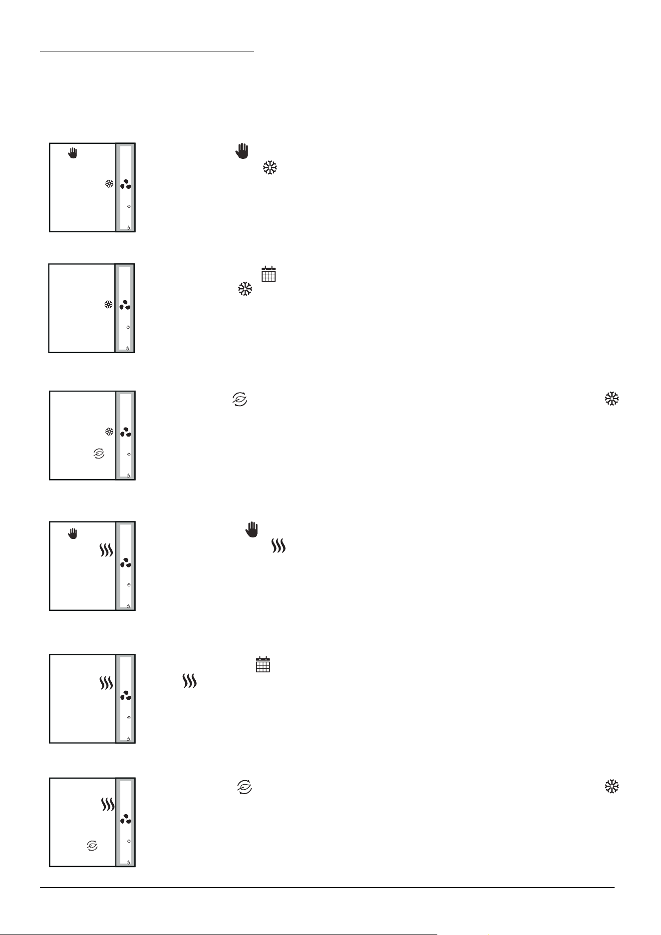
Modes for programmable thermostat
If you have Manual Heat/Cool selection, these are the 6 possible combinations you can have by quick press
of the Mode button:
M
The calendar icon indicates that the thermostat is following the schedule. The
snowflake icon indicates that it is running in Cooling Mode.
M
1.
2.
5.
3.
4.
6.
The Hand icon indicates that the thermostat is in permanent override (manual mode).
The snowflake icon indicates that the thermostat is in Cooling Mode. You can set a
temperature lower than the current temperature and the Fan Coil will maintain it until
you exist the permanent override or set a new setpoint.
The Leaf icon indicates that the thermostat is in Eco Mode. The snowflake icon
indicates that the thermostat is in Cooling Mode. When in Eco Mode, the thermostat will
use Eco setpoint to control room temperature. You cannot change the temperature in
Eco Mode.
The Hand icon indicates that the thermostat is in permanent override (manual
mode). The heat icon indicates that the thermostat is in Heating Mode. You can set a
temperature higher than the current temperature and the Fan Coil will maintain it until
you exit the permanent override or set a new setpoint.
The Calendar icon indicates that the thermostat is following the schedule. The heat
icon indicates that it is running in Heating Mode.
The Leaf icon indicates that the thermostat is in Eco Mode. The snowflake icon
indicates that the thermostat is in Heating Mode. When in Eco Mode, the thermostat
will use Eco setpoint to control room temperature. You cannot change the temperature
in Eco Mode.
M
M
M
M
M
M
M
M
M
14 Fan Coil FC600 Instructions Manual
Schedule Auto Mode. The A icon
M
and calendar icon indicate that the temperature
will be set depending on your created schedules and the thermostat will change between
the Heating/Cooling modes automatically.
If your thermostat is set to Auto Heat/Cool selection, these are the 3 possible combinations you can have by
short pressing the Mode Button:
1.
2.
3.
The A icon
M
indicated that the thermostat is running in auto heat/cool changeover
mode. The hand icon shows Permanent Override Mode (manual). You can set a
temperature depending on the auto heat/cool changeover setpoint temperature.
Eco Mode with auto heat/cool changeover. The A icon
M
and leaf icon indicate
that the temperature will be set using Eco temperature setpoint. You cannot change
the setpoint in Eco Mode.
By long pressing the Mode Button
M
on your Fan Coil, you can:
• Set Time and Date
• Create Schedules
• Access Offset Function
M
Note: Setting the date and creating schedules is available only when the thermostat is programmable (time and
offset are available always). As default, the thermostat is configured as digital (non-programmable) thermostat.
If you would like to change the thermostat from digital to programmable, you need to change d00 parameter
from 0 to 1 (please see page 49).
2.8. Other Mode Button Functions
M
M
M
M
M
M
M
00:00
3 sec
15 Fan Coil FC600 Instructions Manual
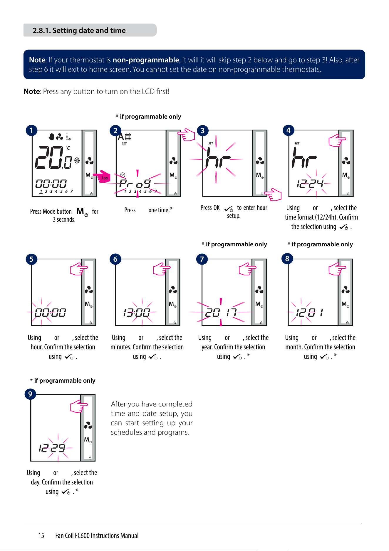
2.8.1. Setting date and time
Note: If your thermostat is non-programmable, it will it will skip step 2 below and go to step 3! Also, after
step 6 it will exit to home screen. You cannot set the date on non-programmable thermostats.
Note: Press any button to turn on the LCD first!
M
M
M
M
M
M
Press Mode button
M
for
3 seconds.
Press OK
M
to enter hour
setup.
Using
M
or
M
, select the
time format (12/24h). Conrm
the selection using
M
.
Using
M
or
M
, select the
hour. Conrm the selection
using
M
.
Using
M
or
M
, select the
minutes. Conrm the selection
using
M
.
Using
M
or
M
, select the
year. Conrm the selection
using
M
. *
Using
M
or
M
, select the
month. Conrm the selection
using
M
. *
Using
M
or
M
, select the
day. Conrm the selection
using
M
. *
Press
M
one time.*
M
M
M
After you have completed
time and date setup, you
can start setting up your
schedules and programs.
* if programmable only
* if programmable only * if programmable only
* if programmable only
1
5
6 7
8
2 3
4
9
3 sec
16 Fan Coil FC600 Instructions Manual
M
M
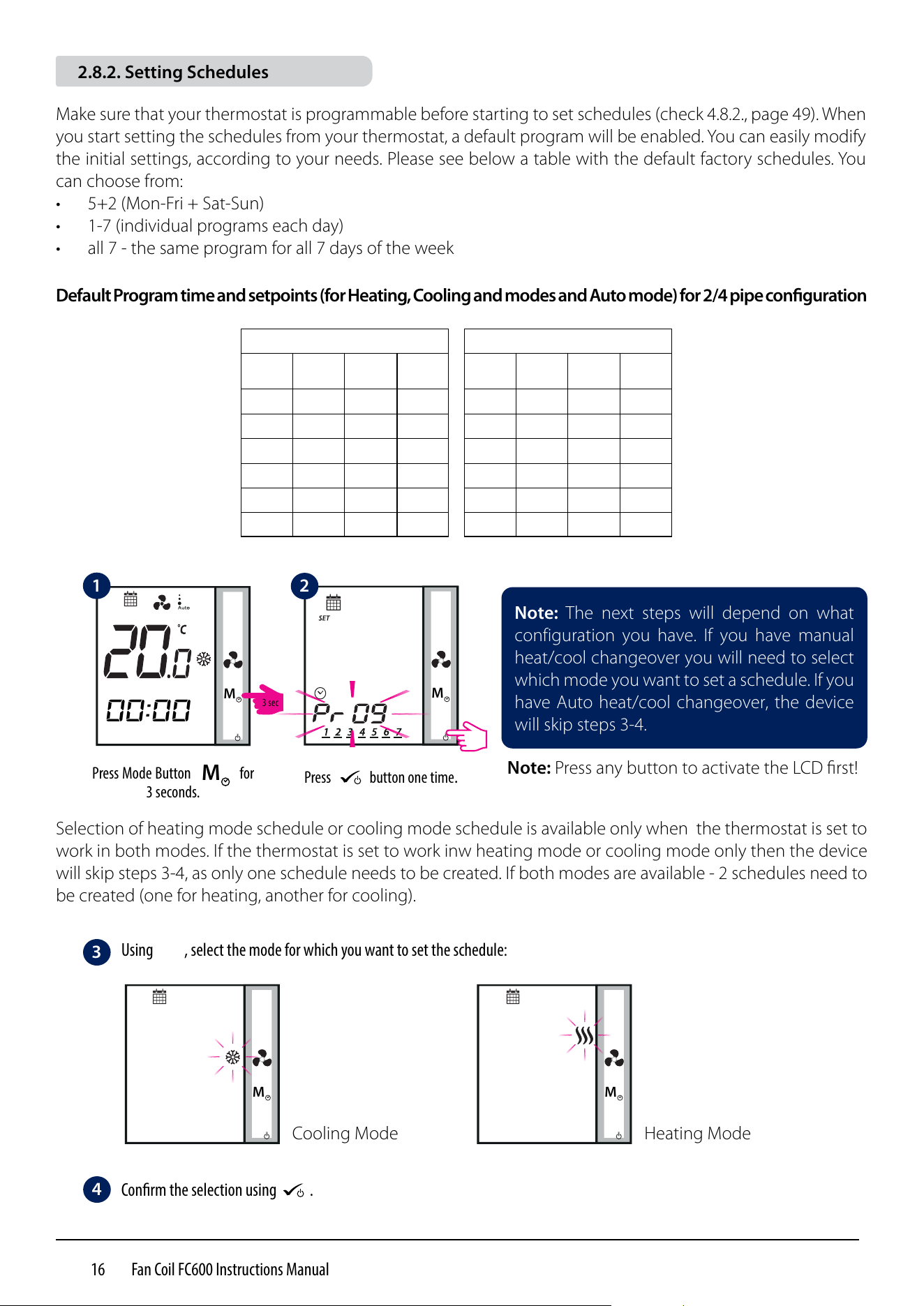
Make sure that your thermostat is programmable before starting to set schedules (check 4.8.2., page 49). When
you start setting the schedules from your thermostat, a default program will be enabled. You can easily modify
the initial settings, according to your needs. Please see below a table with the default factory schedules. You
can choose from:
• 5+2 (Mon-Fri + Sat-Sun)
• 1-7 (individual programs each day)
• all 7 - the same program for all 7 days of the week
Default Program time and setpoints (for Heating, Cooling and modes and Auto mode) for 2/4 pipe conguration
Note: The next steps will depend on what
configuration you have. If you have manual
heat/cool changeover you will need to select
which mode you want to set a schedule. If you
have Auto heat/cool changeover, the device
will skip steps 3-4.
2.8.2. Setting Schedules
Selection of heating mode schedule or cooling mode schedule is available only when the thermostat is set to
work in both modes. If the thermostat is set to work inw heating mode or cooling mode only then the device
will skip steps 3-4, as only one schedule needs to be created. If both modes are available - 2 schedules need to
be created (one for heating, another for cooling).
Note: Press any button to activate the LCD first!
Press Mode Button
M
for
3 seconds.
Press
M
button one time.
M
00:00
M
1
2
Using
M
, select the mode for which you want to set the schedule:
Conrm the selection using
M
.
Cooling Mode Heating Mode
3
4
3 sec
M
5 days (Monday - Friday)
Program Time
Heating
Mode
Cooling
Mode
1 6:00 21°C 24°C
2 23:00 19°C 28°C
3 --:-- --:-- --:--
4 --:-- --:-- --:--
5 --:-- --:-- --:--
6 --:-- --:-- --:--
2 days (Saturday - Sunday)
Program Time
Heating
Mode
Cooling
Mode
1 6:00 21°C 24°C
2 23:00 19°C 28°C
3 --:-- --:-- --:--
4 --:-- --:-- --:--
5 --:-- --:-- --:--
6 --:-- --:-- --:--
17 Fan Coil FC600 Instructions Manual
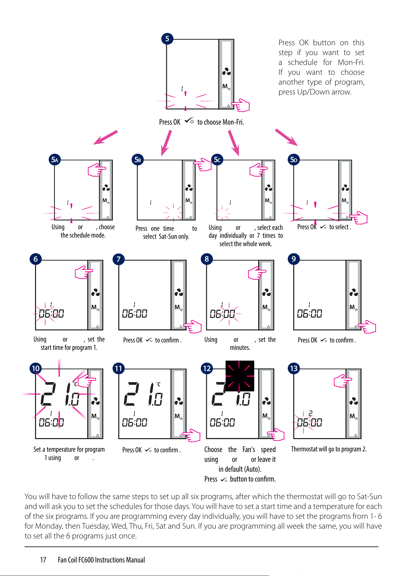
Choose the Fan's speed
using
M
or
M
or leave it
in default (Auto).
Press
M
button to conrm.
M
M
M
You will have to follow the same steps to set up all six programs, after which the thermostat will go to Sat-Sun
and will ask you to set the schedules for those days. You will have to set a start time and a temperature for each
of the six programs. If you are programming every day individually, you will have to set the programs from 1- 6
for Monday, then Tuesday, Wed, Thu, Fri, Sat and Sun. If you are programming all week the same, you will have
to set all the 6 programs just once.
Press one time
M
to
select Sat-Sun only.
Press OK
M
to choose Mon-Fri.
Press OK button on this
step if you want to set
a schedule for Mon-Fri.
If you want to choose
another type of program,
press Up/Down arrow.
M
1
5
Press OK
M
to conrm .
M
2
06:00
Thermostat will go to program 2.
M
1
06:00
Press OK
M
to conrm .
M
1
06:00
Using
M
or
M
, set the
minutes.
M
1
06:00
Press OK
M
to conrm .
M
1
06:00
Set a temperature for program
1 using
M
or
M
.
M
M
1
06:00
Using
M
or
M
, set the
start time for program 1.
M
1
Using
M
or
M
, choose
the schedule mode.
M
1
M
1
Using
M
or
M
, select each
day individually or 7 times to
select the whole week.
M
1
Press OK
M
to select .
M
1 1
06:00 06:00
M
5A 5B 5C 5D
6
7
8
9
10 11 12
13

18 Fan Coil FC600 Instructions Manual
• During program setting, long press
M
will save all settings and exit to home display.
• Program schedule time is a 10 minute step.
• If the selected days of week are 1-5+6-7, after you set the schedule for 1-5, the Fan Coil will automatically
go to programming 6-7.
• If you are programming whole week the same - after you finish programing schedule for days 1-7, the Fan
Coil will exit program setting mode.
• If the selected weekday is Monday, after the program setting is finished, the unit will automatically enter
program setting of Tuesday, then Wednesday, Thursday, Friday, Saturday and Sunday, finally exit the program
setting mode.
• Long press
M
or
M
is only to change fast time and temperature.
• At any time of setting, long press
M
to return to the home display while saving your settings.
• The selected item will not flash if it is being adjusted. Flashing will resume about 0.5 seconds after key
release.
• The unit will return to home display after 30 seconds if no key is pressed, storing the program settings
which have been made. The unit will run as per the new program settings.
• The starting time of the next program cannot be equal or earlier than the previous one. For example in the
first program starts at 8:00, the next has to start at least 8:10 etc.
During program setting, few notes:
19 Fan Coil FC600 Instructions Manual
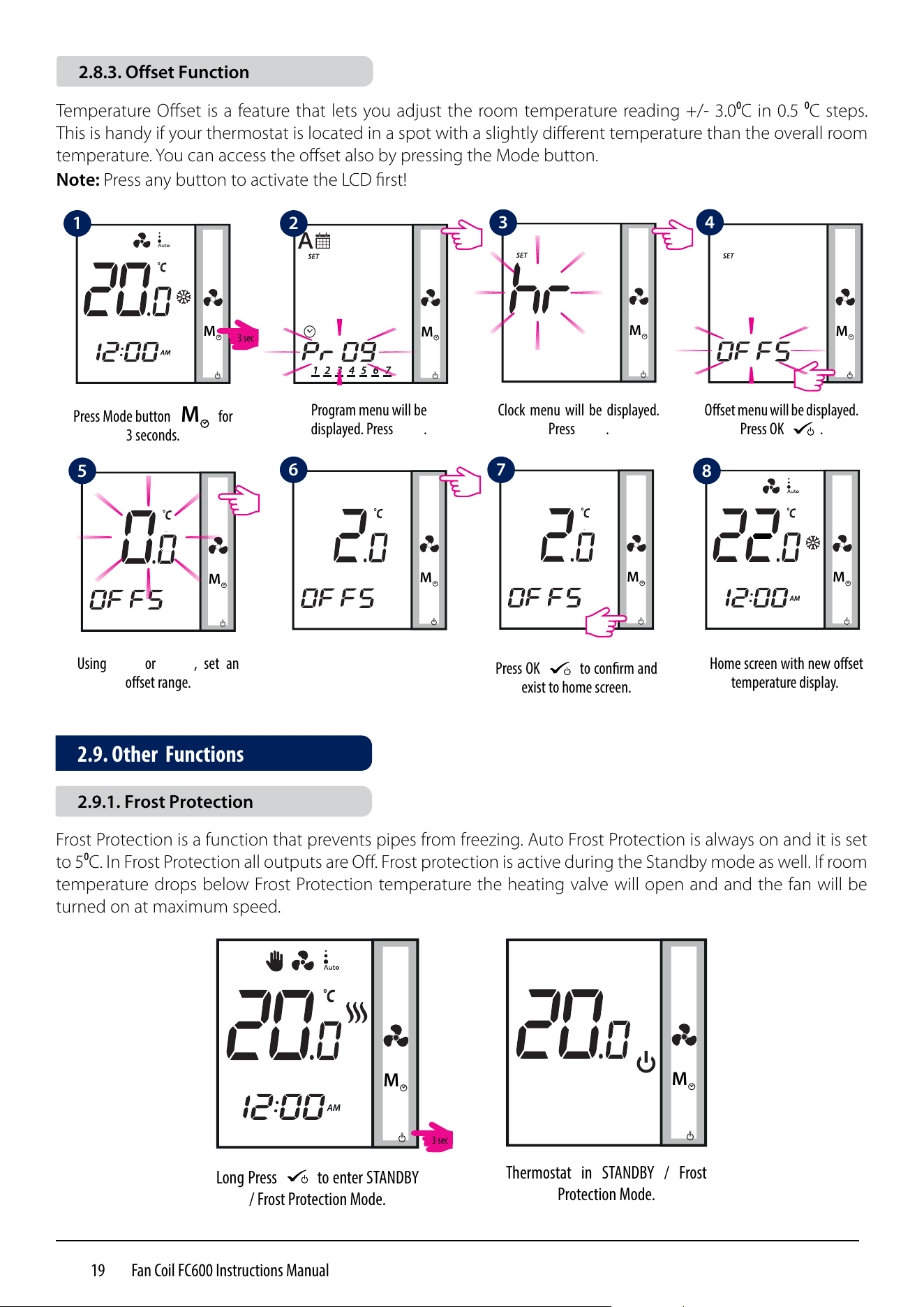
Frost Protection is a function that prevents pipes from freezing. Auto Frost Protection is always on and it is set
to 5⁰C. In Frost Protection all outputs are Off. Frost protection is active during the Standby mode as well. If room
temperature drops below Frost Protection temperature the heating valve will open and and the fan will be
turned on at maximum speed.
M
Long Press
M
to enter STANDBY
/ Frost Protection Mode.
M
Thermostat in STANDBY / Frost
Protection Mode.
Temperature Offset is a feature that lets you adjust the room temperature reading +/- 3.0⁰C in 0.5 ⁰C steps.
This is handy if your thermostat is located in a spot with a slightly different temperature than the overall room
temperature. You can access the offset also by pressing the Mode button.
Note: Press any button to activate the LCD first!
M
M
M
M
Press Mode button
M
for
3 seconds.
Program menu will be
displayed. Press
M
.
Clock menu will be displayed.
Press
M
.
Oset menu will be displayed.
Press OK
M
.
Using
M
or
M
, set an
oset range.
Press OK
M
to conrm and
exist to home screen.
M
Home screen with new oset
temperature display.
M
M
M
M
M
1
5
6
2
3
4
7
8
2.9. Other Functions
2.8.3. Offset Function
2.9.1. Frost Protection
3 sec
3 sec
20 Fan Coil FC600 Instructions Manual
Regardless the mode the Fan Coil is operating in - heating (including Frost Protection) or cooling mode, once
the external sensor is disconnected or malfunctioning, the thermostat shows alternately the warning letters
for 2 seconds and current temperature for 2 seconds to warn the user the external sensor is disconnected or
malfunctioning. At the same time, the LCD backlight will turn on when the warning letters are displayed, then
turn off when current temperature is displayed.
Error Code Description
01 Pipe sensor input is open or pipe sensor is not connected
02 Pipe sensor input short circuit
03 External sensor open or external sensor is not connected
04 External sensor short circuit
When the external sensor is reconnected or fixed, thermostat will return to Normal mode and display the
current room temperature.
When Err XX appears, the thermostat will be closed.
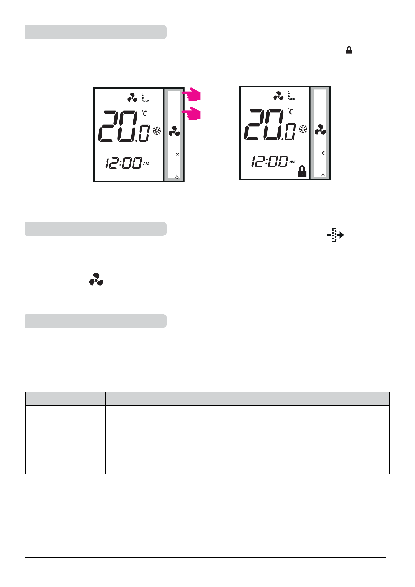
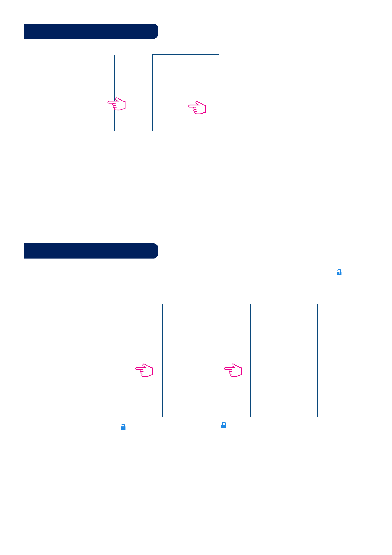
To lock the keys on the thermostat, please press
M
and
M
together. LCD shows key lock icon
M
. To unlock
the keys, press the same keys together again.
M
Press together
M
and
M
for 3
seconds.
M
Keys locked.
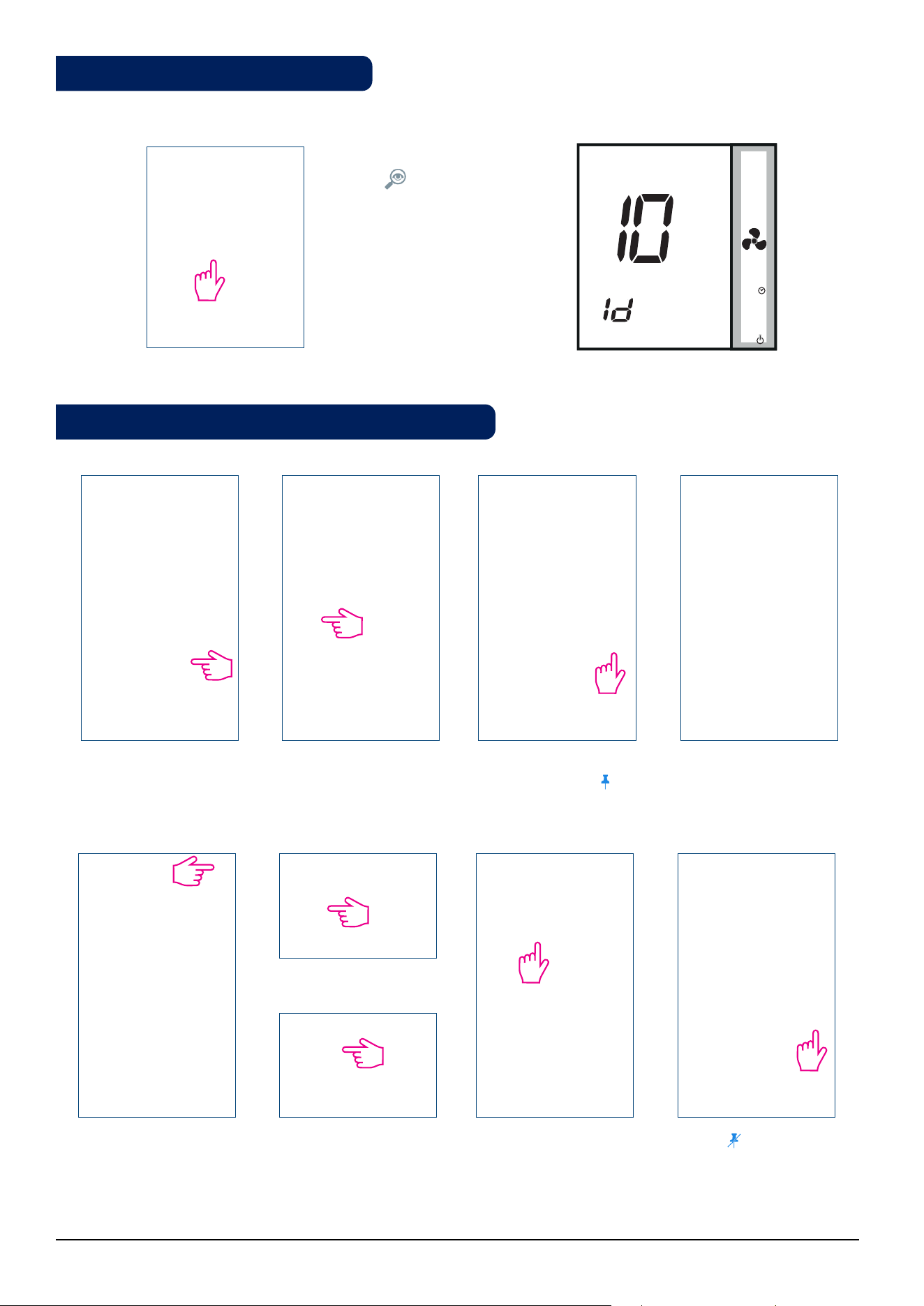
The 'clean fan filter reminder' function counts the fan operating hours and displays the icon to remind the
user to clean the fan filter as soon as the threshold is reached. This does not impact the thermostat's operation,
which continues to run normally.
M
Long press button for 5 seconds to cancel filter reminder.
M
M
2.9.2. Key Lock Function
2.9.3. Service Filter Reminder
2.9.4. Error Codes
3 sec
3 sec
21 Fan Coil FC600 Instructions Manual
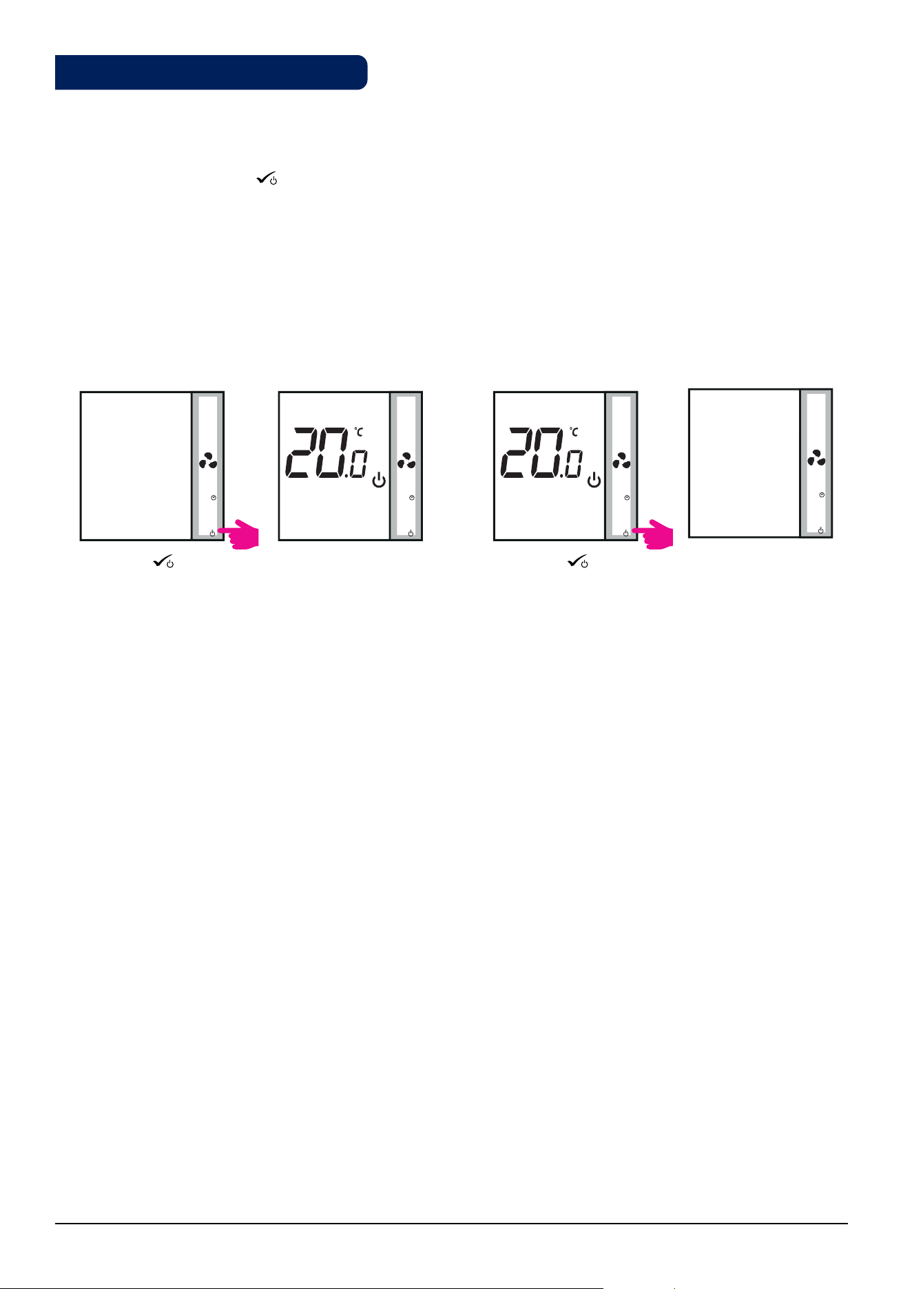
2.10. STANDBY Mode
You can enter STANDBY Mode and protection setpoint will be activated. The clock continues running, as well
as the temperature sampling. Protection heating and cooling setpoints are activated. To enter STANDBY Mode,
long press the OK button
M
on your thermostat. You can always switch back off STANDBY Mode by long
pressing the OK button. All relay outputs immediately change to OFF, regardless of the previous operating
mode (heat, cool, auto heat/cool). All your preset settings will be stored. When FC600 works in Standby mode,
the Frost Protection is running.
Enter STANDBY Mode Exit STANDBY Mode
Press OK
M
for 3
seconds.
Press OK
M
for 3
seconds.
STANDBY Mode. Previous Mode.
• Note: Press any button to activate the LCD first!
M
M
M M
3 sec 3 sec
22 Fan Coil FC600 Instructions Manual
3. Operation Manual (Online Mode)
This section will show how to use your Fan Coil with the Universal Gateway and the Salus Smart Home App.
In order to do that, you will be needing a Salus Universal Gateway UG600/UGE600, the Salus Smart Home App
and Internet connection. Controlling your thermostat via the App gives you a lot of freedom and the possibility
to manage the temperature in your house/office remotely.
Thermostat tile on the App Thermostat tile when tapped
Thermostat interface
3.1. Quick Overview
The functions available on the App are:
• Device name changing
• Setting room temperature setpoint
• Heat/Cool Selection
• 4 different work statuses: Follow schedule, Permanent Hold, Eco Mode, Off (StandBy Mode)
• Schedule programming
• Fan speed control
• Key Lock Function
• Pin/Unpin thermostat to dashboard
• Window association function
• Identification function
• Service Settings
• Creating/Setting One Touch rules
23 Fan Coil FC600 Instructions Manual
3.2. App screen Icon Description
Heat/Cool Icon
Change of heating / cooling modes.
If heating / cooling is switched
automatically, the button is inactive.
On/O/Schedule/Eco/Hold
Tap for submenu
Fan Speed/O/On
Tap for submenu
Lock/Unlock thermostat
Pin/Unpin
thermostat to
dashboard
Settings ButtonWindow sensor button
Find your device
Menu Button
Home Screen Button
Edit thermostat name
Set Temperature
Current Temperature
Back Button
Manually adjust temperature
24 Fan Coil FC600 Instructions Manual
You can easily change the name of your device at any moment, by tapping the pencil screen on your device
name panel.
Tap pencil icon . Enter a new name. Tap Save. Thermostat renamed.
You can change the set point by sliding the cursor to left/right on your App. On your App screen, the setpoint
temperature is the number displayed in a larger font.
Old setpoint.
New setpoint.
Sliding the cursor to the left will decrease the temperature, and to the right - will increase. If your thermostat is on
permanent hold, it will follow the setpoint temperature until you manually change it again. That is permanent
override. if the thermostat is running in schedule mode, but you have manually set another temperature,
the new set temperature will run until the next program starts. Make sure that the thermostat operates in
heating mode in you want to set a temperature that is higher than the current room temperature and that the
thermostat is in cooling mode if you want to set a temperature that is lower than the actual room temperature.
Click on thermostat tile to
enter your thermostat.
Click on thermostat name
to enter main screen.
3.3. Device name change
3.4. Temperature Setpoint
25 Fan Coil FC600 Instructions Manual
The Fan Coil gives you possibility to select between heating or cooling modes via App if the thermostat is set
on manual heat/cool change over. To do that, follow these simple steps:
Click on thermostat tile to
enter your thermostat.
Click on thermostat name to
enter main screen.
Tap to select mode. Select Cool/Heat mode.
Note: While in Manual Mode you want to set a temperature that is higher than the current room
temperature, you need to choose Heat Mode before changing the Setpoint to the new value. If you want to
set a temperature that is lower than the current temperature in the room, you need to choose Cool Mode
before changing the Set point to the new value. Otherwise the thermostat will not respond.
App icons for Heat and Cool
Icon Explanation
When thermostat is in HEATING mode, but is not calling for HEAT
When thermostat is in HEATING mode and is calling for HEAT
When thermostat is in COOLING mode, but is not calling for COOL
When thermostat is in COOLING mode and is calling for COOL
gray
orange
blue
gray
Thermostat tile on
the dashboard when
thermostat is in
Heating Mode and
calls for heating.
Thermostat tile on
the dashboard when
thermostat is in
Cooling Mode and
calls for cooling.
3.5. Heat/Cool selection

26 Fan Coil FC600 Instructions Manual
Tap to enter sub-menu.
Tap follow schedule .
The thermostat is following
the schedule.
Your Fan Coil can have 4 different work statuses:
1. Follow schedule
2. Permanent Hold
3. Eco Mode
4. Off (STANDBY Mode)
You can choose the status by tapping the work-status icon.
Choose this operating mode for the thermostat to follow the programmed schedules. When the thermostat runs
in schedule mode, the calendar icon will be displayed. If the thermostat runs in temporary override mode
(the user manually changed the temperature during the program), the hand and the calendar icon will
be displayed together. When in temporary override, the thermostat will return back to following the schedule
after a new program set time begins.
Even if the thermostat is set to following a schedule, the user can change the operating mode to the Permanent
Hold one. In Permanent Hold the thermostat will maintain the set point temperature until the user will manually
change it to a new value, or select a new operating mode. When the thermostat runs is Permanent Hold, the
hand icon will be displayed on the App screen.
Tap to enter sub-menu.
Tap hand icon .
The thermostat is in
permanent hold.
3.6. Work Status
3.6.1. Follow Schedule
3.6.2. Permanent hold
27 Fan Coil FC600 Instructions Manual
When in Eco mode, the thermostat will use Eco set point to control room temperature. When Eco mode is
activated, the Eco icon will be displayed. To select Eco mode, follow the easy steps.
Note: When thermostat operates in Eco Mode, you cannot set a new temperature set point by sliding the
cursor. After thermostat exists Eco Mode, it returns to the previous set mode.
Eco set point setting parameter is d10 for heating mode and d11 for cooling mode. The default set point
temperature is 30°C for cooling mode and 15°C for heating mode. To change that, please refer to settings in
Installer Section.
Note: If you have an occupancy sensor, then the Eco Mode will be activated automatically when the set up
is complete. This is the default d34 setting. You can choose from either Eco or STANDBY mode.
Tap the work status icon. The thermostat is running
in Eco Mode.
Select Eco Mode .
Note: If the occupancy sensor is installed, the Eco Mode via app is disabled. On the LCD, the man in door
symbol will be displayed if the occupancy sensor detects presence. When the occupancy sensor does not
detect presence, the man in door symbol disappears and the Eco Mode via app is enabled. This is the
default d34 setting. For more information regarding the installer mode, please check page 54.
3.6.3. Eco Mode
28 Fan Coil FC600 Instructions Manual
In STANDBY Mode all the outputs from the thermostat are off. It will still display the current room temperature
and the thermostat will be working in Frost Protection. When the thermostat is running in STANDBY Mode, you
cannot change the temperature set point or control the operations in any way.
Please follow the steps below.
Note: After the thermostat exits Standby Mode, all the settings will be restored.
Tap the work status icon. The thermostat is running
in STANDBY Mode.
Select O .
Tap On/O icon.
Select On .
Thermostat in previous
mode.
3.6.4. STANDBY Mode
29 Fan Coil FC600 Instructions Manual
3.7. Setting a schedule for the thermostat
The Fan Coil gives you the possibility to set schedules for the thermostat. You can add up to 6 programs during
one day, by selecting the program's start time and temperature. You can choose from 3 different schedule
configurations:
• 5+2 (5 days same program + 2 days same program)
• Individual every week day
• All 7 days same program
Additionally, you can choose to set the Default schedules that already exist in the App, or to modify them
according to your preferences. The schedules are displayed on the bottom of screen of your App on the selected
thermostat. You can activate the schedules by pressing the Follow Schedule icon on your App.
Once activated, the calendar icon will appear on your screen.
Go to your thermostat,
scroll down and tap on
pencil icon .
Click on arrow and
a drop-down menu
with days options will
be displayed.
You can choose Mon-
Fri+Sat-Sun program
(5+2).
All 7 days same
program.
Individual every week
day.
To add a program to your thermostat, follow the following steps to add interval and repeat as many times as
needed.
Tap Add interval.
Add a start time.
Choose Fan's speed. To add interval, tap
Add.
Note : Depending on your initial settings, whether you have selected or not a default schedule, the intervals
will be displayed. If you didn't choose any default schedules, there would be no time intervals to display.
You can always add default schedules by clicking the button. Default schedules can be easily
edited according to your preferences.
Add temperature.
Note: The time should be in hh:mm format and the temperature value should be a number between 5 and
40. Decimal digits must end in 0 or 5.
1
2
2A
2B 2C
3 4
5
6
7
30 Fan Coil FC600 Instructions Manual
After you added the
interval, tap Save to
save it.
If you want to add more intervals, tap Add new interval
and repeat the procedure as from step 4 to 8.
You can add as many
intervals as you wish by
repeating the procedure
described from steps 4
to 8. The procedure is the
same for all 3 schedule
configurations. You can
customize the programs
on the thermostat in any
way you want.
Note: If you selected Heating or Cooling ONLY in your initial setup, only ONE field (Heating or
Cooling) will be displayed and only that one will require a value input.
Tap Default Schedule. Default schedules are
added. You can edit
them by pressing the
pencil icon .
If you want to add a default schedule, follow the steps below.
Make your changes
using the steps 4-8 and
tap Update.
Your schedule has been
successfully updated.
You can delete undesirable intervals by:
Tap Sign . Delete button will
appear. Tap it.
Interval deleted.
8 9
10
11 12 13 14
1
2
3
31 Fan Coil FC600 Instructions Manual
Tap on fan icon. Choose fan speed.
Tap the fan icon on your App screen and a
sub-menu with fan speeds (1-3, Auto and
Off ) will appear. Make your selection.
By default, the Fan is on only when the Fan Coil calls for heating or cooling. You can change the default setting
by changing parameter d38 in Installer Mode. On details regarding the installer mode, please check page 55.
The fan is controlled by the TPI method. TPI is a learning algorithm for the fan. It tells the fan in which speed it
has to run in order to be most economy efficient. Not that it only sets the speed depending on the difference
between the room temperature and the set point temperature, it also figures out the thermo patterns in your
house/office to result into the best energy saving plan.
The application gives you the possibility to lock the keys on your device. Simply tap the lock icon on the
screen to lock. To unlock, tap it again. When the keys are locked, the user can't press any keys on the device.
Tap lock icon .
Thermostat locked. Tap
to unlock.
Thermostat unlocked.
The button lock settings can also be changed in the parameter settings by changing the value of the
parameter "d37" (permission to unlock the thermostat from the device level) or the value "d43" (enabling the
change of the set temperature despite the locked buttons) - more information in chapter 4 - Installer Mode.
3.8. Fan Control
3.9. Key lock function
32 Fan Coil FC600 Instructions Manual
If you have an occupancy sensor connected to your S2 terminal, for example a hotel card, it will also show
on the App. When the card will be inserted, meaning man in room, the icon will be displayed on your screen.
Otherwise, an empty door will show. The user can define if thermostat should go to ECO mode or STANDBY
mode when there is nobody in the room, by changing the parameter d34 in Installer Menu.
Man in room .
Empty room -
thermostat in Eco Mode.
The window sensor associated with the thermostat will allow you to create certain rules when the window is
closed/open. If the information about an open/closed window is received during one of the programs (when
the thermostat is following a schedule), than the rule will be applied until the next program starts. Also, you
can chose that the thermostat will follow the previous mode after the window is closed. In order to have this
function available, you need to have window sensor added to your system and add it to the thermostat. Please
see below.
To add a window sensor to you system, please refer to SW600/OS600 manual on www.salus-manuals.com
Tap window icon . Select the option and the
associated sensor.
Tap Save to save your
settings.
3.10. Occupancy Sensor
3.11. Window Association Function
33 Fan Coil FC600 Instructions Manual
Tap the magnifying glass
icon on your App
screen. The screen on
your device will go to
identification mode - it
will flash On/Off during
10 minutes. Tap it again
to stop identification
mode.
M
Thermostat is pinned to
the dashboard. Tap to
unpin.
Tile is visible. Thermostat is pinned to the
dashboard.
Thermostat unpinned.
Tap thermostat.Tile is no longer visible. To
access the thermostat go
to Menu.
Tap Equipment.
Tap All equipment.
Tap to pin back.
3.12. Identication Function
3.13. Pin / Unpin thermostat to the dashboard
34 Fan Coil FC600 Instructions Manual
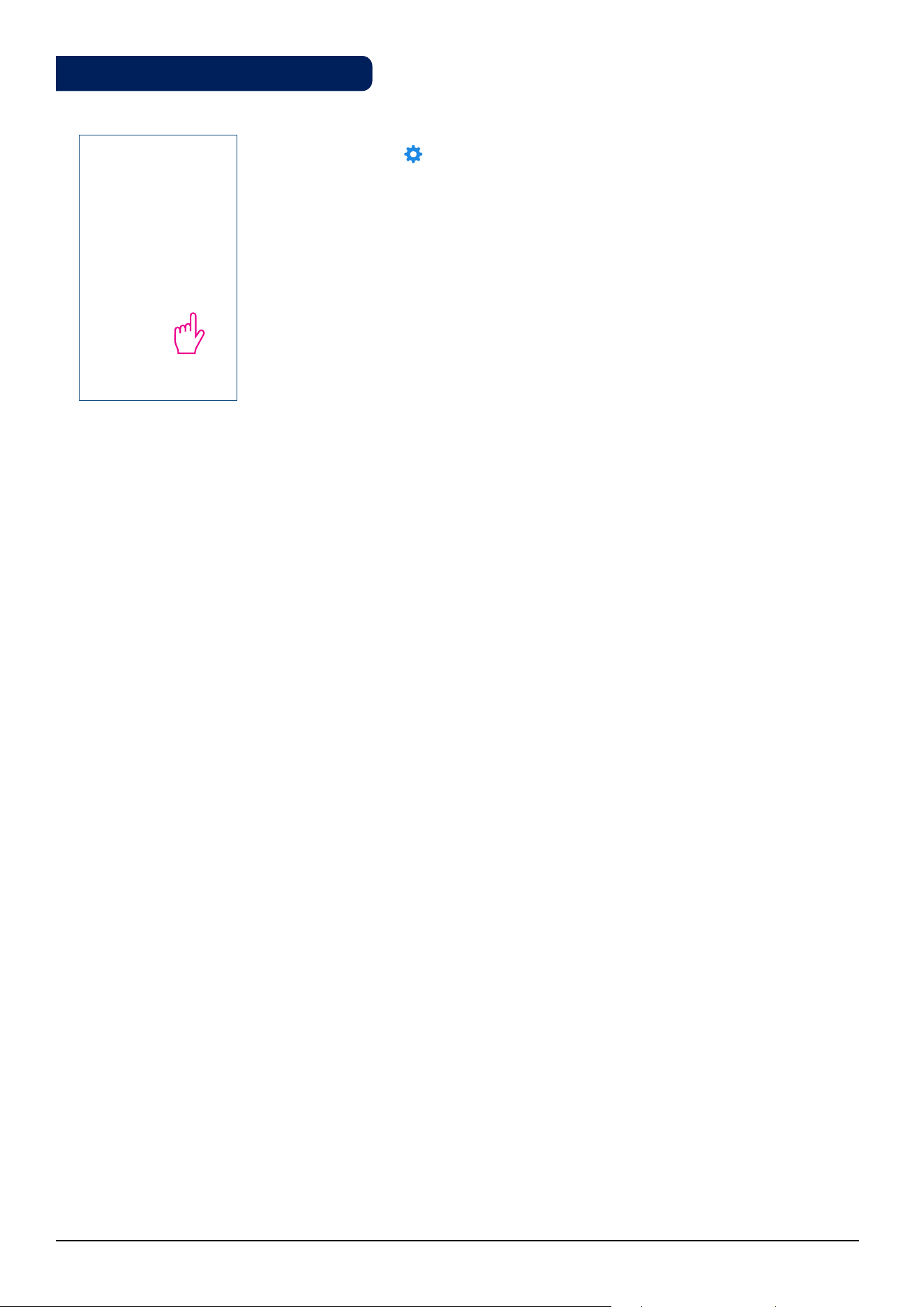
Tap the gear icon to enter settings. This menu allows you to change settings
on your thermostat.
Please read more in the Installer Manual section about more detail on how to
access the settings with a full description of the parameters. See page 51.
3.14. Service Settings
35 Fan Coil FC600 Instructions Manual
OneTouch is a set of rules that can be applied to your thermostat. You can choose to enable or disable them any
time. OneTouch tells your thermostat exactly how to behave depending on your input. There are 3 predefined
OneTouch rules in the App:
• Party mode - sets the thermostat on 21 C for 2 hours
• Run comfort temperature - Set thermostat to 21 C
• Run frost mode - Set thermostat to frost mode
To activate a pre-existing OneTouch, please follow the steps below. For example, you want to set the Party
Mode OneTouch
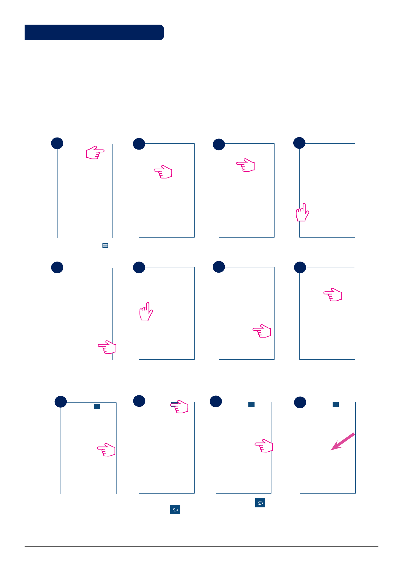
Tap the menu icon . Select OneTouch. Tap on Party Mode.
Tap Add OneTouch. Choose devices you
want to apply the rule
to.
The OneTouch is added.
Press the button to get
the OneTouch running.
One Touch tile
appears on your home
screen and thermostat
went blue meaning it is
cooling down.
Your thermostat is set
to 21 ⁰C.
Go to home screen by
tapping .
Tap Apply.
Select Settings.
1
2
3
4
5 6
7
8
9
10
11
12
3.15. Using / Adding OneTouch
36 Fan Coil FC600 Instructions Manual
4. Installer Manual
Your box should contain:
Front housing of the Fan Coil
Rear housing of the Fan Coil
Two screws for wall
mounting
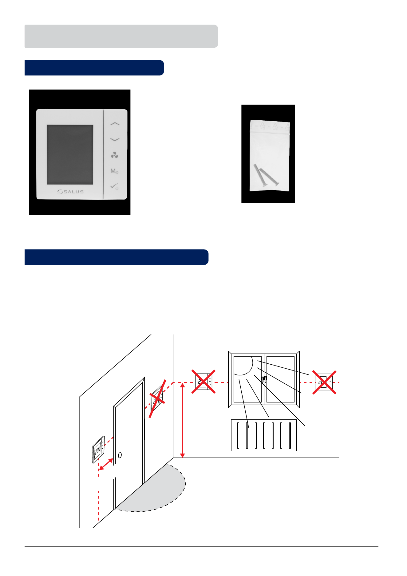
The ideal position to locate the FC600 thermostat is about 1.5m above floor level, in a location where the
thermostat is accessible, reasonably lit and free from extremes of temperature and draughts. Do not mount the
thermostat on an outside wall, above a radiator or in a location where it may be subjected to direct sunlight.
Quick Guide
M
M
150 cm
min 20 cm
4.1. Box Contents
4.2. Proper positioning of the thermostat

37 Fan Coil FC600 Instructions Manual
Below you can find some possible usage diagrams for the Fan Coil thermostat, depending on the on your
system and components.
• 2 pipe, heating only
• 2 pipe, cooling only
4.3. Idea diagrams

38 Fan Coil FC600 Instructions Manual
• 2 pipe, heating OR cooling
• 4 pipe, heating AND cooling
39 Fan Coil FC600 Instructions Manual
• 4 pipe, heating AND cooling + S1changeover switch
Heating mode
Cooling mode
External switch (ON/OFF) (heat/cool changeover)
External switch (ON/OFF) (e.g. an occupancy sensor, launching ECO or Standby mode)
Pipe temperature sensor (allows the fan to be working or not)
Air temperature sensor or external room temp. sensor (FC600 will display temperature
from the sensor connected to T2. Internal temperature sensor will be ignored)
Motorized valve / actuator
3-gear speed fan
Heating device
Cooling device
Heating or cooling device (2-pipe system only)
40 Fan Coil FC600 Instructions Manual
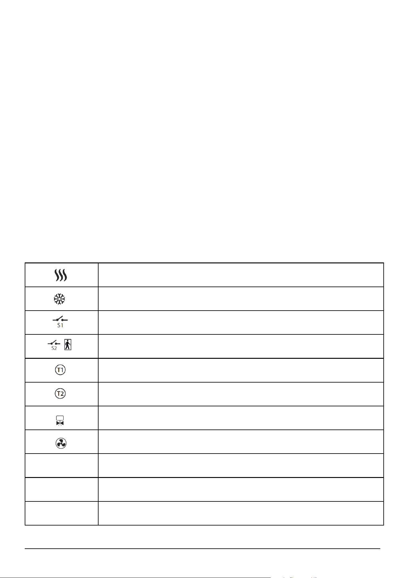
FC600
L
S2
S1
*
FUSE
FAN
AC 230V
4-PIPE
V1 - HEATING, V2 - COOLING
2-PIPE
V1 - HEATING/COOLING
N
V2
IIIII I
F3 F2 F1 V2
S2
5(2)A
S1
COM
V1 N L
V1
V1
T1T2
FC600
L
S2
S1
*
FUSE
FAN
AC 230V
4-PIPE
V1 - HEATING, V2 - COOLING
2-PIPE
V1 - HEATING/COOLING
N
V2
IIIII I
F3 F2 F1 V2
S2
5(2)A
S1
COM
V1 N L
V1
V1
T1T2
- 3-gear speed fan
- Fuse
- Zone valve
- External switch (ON/OFF) - heat/cool changeover
- External switch (ON/OFF)
e.g. an occupancy sensor, launching eco mode
- Air temperature sensor or external room temp. sensor
(active T2 sensor disable temperature measurement in thermostat)
- Pipe temperature sensor - allows fan to work
*(only in 2-pipe system)
Terminals description Icon description
S1
S2
*
T1
T2
Terminal Function
L,N 230V AC power supply
V1
4 pipe: Heating valve output - 230V AC
2 pipe: Heating or Cooling valve output - 230V AC
V2
4 pipe: Cooling valve output - 230V AC
2 pipe: N/A
F1 Fan Speed control (Low level) - 230V AC
F2 Fan Speed control (Medium level) - 230V AC
F3 Fan Speed control (High level) - 230V AC
S1
Heat/Cool changeover
(or pipe sensor - only in 2-pipe system)*
S2 Occupancy sensor or external sensor
COM Common Terminal
4.4. Wiring options
41 Fan Coil FC600 Instructions Manual
Note: If you are using an external sensor
please make sure that you are following
the sensor instructions below and also
that all the setting are done accordingly
on the fan coil.
S1
NoFn
S1
HCCO
S1
Auto
S1
SenS
No function
Nothing is connected to S1/COM
terminal. The Heat/Cool can be
changed only manually using the
Mode button or the App if both
modes are available.
Heat/Cool Changeover
When the S1/COM terminal
is open, the Heat function is
activated.
When the S1/COM terminal
is closed, the Cool function is
activated
Auto Heat/Cool Changeover
In 2 pipe system - S1 = Auto,
the pipe temperature sensor is
connected, and it is deciding
in what mode the thermostat
should be working.
In 4 pipe system - S1 = Auto -
it means nothing is connected
to S1/COM, and thermostat is
measuring the room temperature
to select the Heating or Cooling
mode.
Fan Sensor
Available for 2 pipe only. Pipe
sensor is connected to the S1/
COM terminal. Pipe sensor is
used to allow the fan to run or
not. Heat/Cool selection is done
manually.
Default setting: S1
NoFn
S2
NoFn
S2
Door
S2
SenS
No function
Nothing is connected to S2/COM terminal.
Occupancy sensor
Occupancy sensor is connected to the S2/COM
terminal (e.g.: hotel card).
External temperature sensor
The temperature read by the sensor will be
displayed on the Fan coil LCD. The internal
sensor in the Fan coil will not be used.
Default setting: S2
NoFn
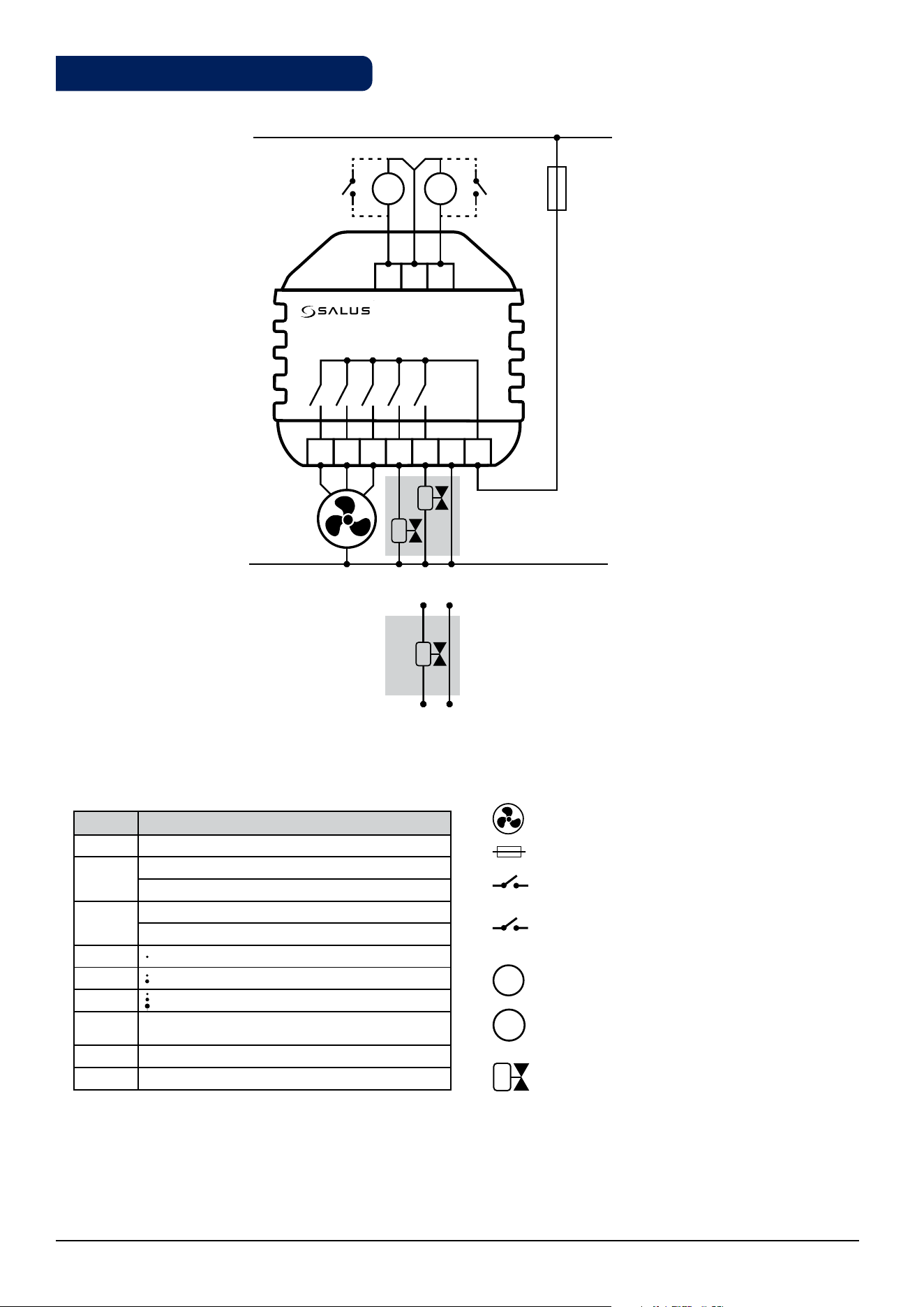
S1 Terminal connection
S2 Terminal connection
S2
S1
T1T2
COM
FC600
F2F3 F1 V2 V1 NL
S2 S1
4.5. Terminals explanation
42 Fan Coil FC600 Instructions Manual
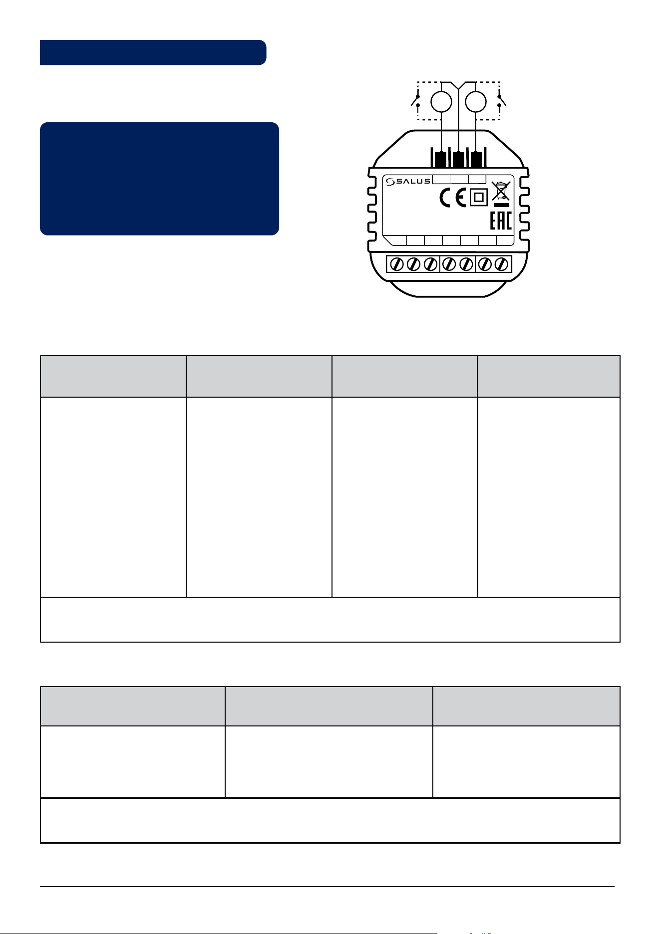
The S1/COM terminal responds for the heat/cool changeover. It can operate in 4 different modes, depending
on what is connected to the terminal.
The S1/COM Terminal
2 pipe 4 pipe
NoFn
No Function, means that there is nothing connected to the terminal and that the Heating/
Cooling mode will be changed manually by the user when operating the Fan Coil via device or
the App. Heating/Cooling mode cannot be
changed via changeover sensor / switch; it will remain in the last mode as selected locally via
button or App.
HCCO
Heat/Cool Changeover via External Switch - an external Switch is connected to the
thermostat and depending on its position the end user can control the Heating/Cooling
modes on the thermostat. When the switch is open the thermostat enters Heating Mode, when
closed - Cooling Mode. The primary usage for this setting is when you have a thermostat in
one room, but wish to operate its mode from a different location (for example you have several
thermostats in different rooms and the Heat/Cool switch placed in the boiler room).
Auto
Auto Heat/Cool changeover via Pipe Sensor. An
external pipe temperature sensor is connected to the
S1/COM terminal. The temperature detected by the
pipe sensor (i.e the water temperature inside the pipe
)is used to change over from heating to cooling mode,
or vice versa. When the pipe temperature is above e.g.
30 °C(parameter d25), the thermostat changes over
to heating mode; and to cooling mode when below
e.g.10°C (parameter d24). If the pipe temperature is
between the 2 changeover points after power-up, the
thermostat starts in the previous active mode. The pipe
temperature is acquired at 30-second intervals and the
operating state is updated accordingly.
Note: The temperature detected by the pipe sensor is
NOT the temperature displayed on your LCD. The screen
of the thermostat displays the room temperature,
detected by the internal temperature sensor. The
information regarding the pipe temperature is used
by the thermostat to ONLY switch between Cooling/
Heating Mode and turn On/Off the fan, if selected.
Auto Heat/Cool changeover via
"dead zone" function. For a 4 pipe
configuration there CANNOT be an
external pipe sensor connected. The
thermostat controls 2 valves - a valve
for heating mode and a valve for
cooling mode. Terminal V1 is used
for the Heating valve, while terminal
V2 is used for the Cooling valve. The
Heating/Cooling mode changeover
temperature is the one detected by
the internal temperature sensor.
SenS
An external pipe sensor is connected to the S1/COM
terminal, that tells the fan to run or not. The type of
sensor connected to the S1/COM terminal need to be
NTC 10kOhm.
N/A
S1/COM
2 or 4 pipe
43 Fan Coil FC600 Instructions Manual
The S2/COM Terminal
The S2/COM terminal is used for connecting external sensors as occupancy or external temperature sensor. It
can operate in 3 different modes, depending on what is connected to the terminal.
2 pipe 4 pipe
NoFn
No Function - nothing is connected to the S2/COM contact. No information is provided to
the thermostat.
Occupancy
sensor
Occupancy Sensor - occupancy sensor is connected, meaning that the thermostat can get
information depending on the input from this terminal and different rules can be created.
An example of an occupancy sensor is the hotel card - once the hotel card is inserted, the
thermostat can operate following a schedule it can go to ECO mode or STANDBY mode
(defined by d34 parameter). Occupancy sensor can be used in 2 pipe or 4 pipe applications.
External
Temperature
Sensor
External Temperature Sensor - External Temperature sensor is connected. Once the sensor
is connected, the thermostat will display on the LCD the temperature from that sensor,
ignoring the internal sensor. It can be used as an extension for the thermostat, saying you
have a thermostat operating a room that you don't have access to or is inconveniently
remote. Please note that if you don't have any sensor installed, but selected S2 as external
sensor, there will be no temperature to display, as there will be no source for the thermostat
to gain data from. Can be operable with any d2 value. The sensor should be NTC 10kOhm.
Note: The S2/COM terminal has the same usage for either 2 or 4 pipe configuration.
2 or 4 pipe
Sensor
Caution: Due to the risk of injury, the thermostat is designed for use in the environment marked as 2 degree of
pollution according to the PN-EN 60730-1. In addition, the thermostat can not be used in condensed conditions
or be exposed to water.
Caution: The installation must be carried out after the thermostat is disconnected from the power supply.
Connecting the mains voltage 230V ~ to the sensor terminals effectively damages the thermostat and creates
danger of electric shock. Before power up, check if the wires are properly connected.
4.6. Wall Mounting
44 Fan Coil FC600 Instructions Manual
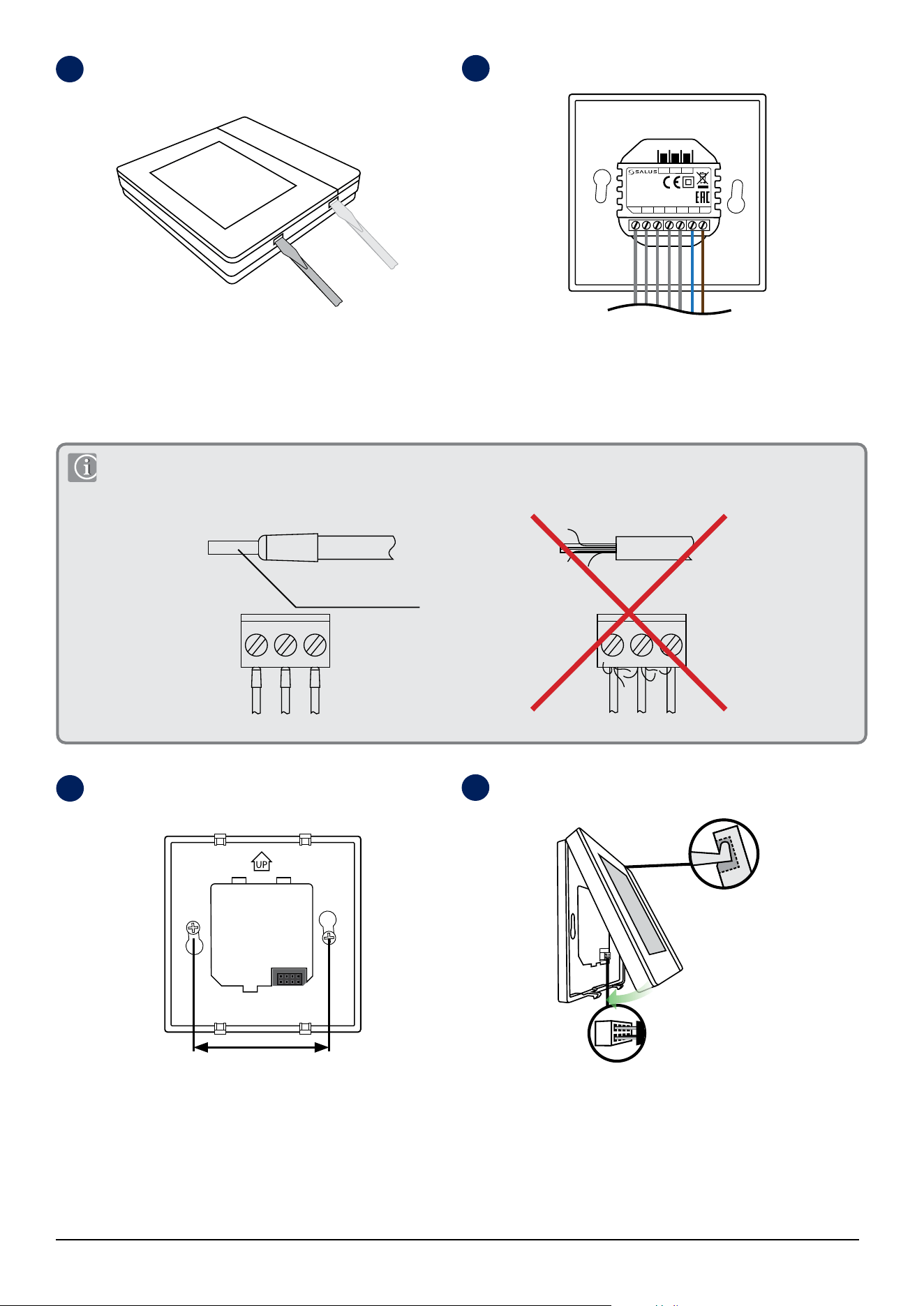
Remove the front cover by prying hooks with at screwdriver at
the bottom of the front panel.
For the convenience of installation, the rst step is to wire the
volt-free wires, then low-voltage wires (S1, S2, COM). Check that
wires are properly connected.
FC600 is designed for ush mounting in a 60 mm wall box.
Make sure the back cover is in place in the appropriate position
(according to the arrow on it).
Fit the front part of the casing to the top edge and make sure
the pins are properly positioned. Push the front of the casing
until you hear positive click.
60 mm
1
3
4
2
The ends of the connecting wires must be protected against delamination using insulated sleeves as shown in the figure
below:
insulated sleeve with a
length of 6 mm
COM
FC600
F2F3 F1 V2 V1 N L
S2 S1
45 Fan Coil FC600 Instructions Manual
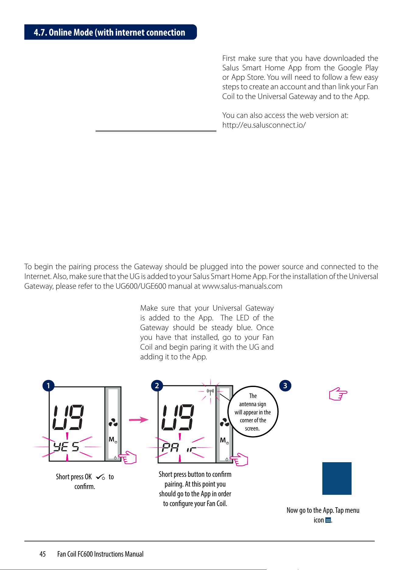
To begin the pairing process the Gateway should be plugged into the power source and connected to the
Internet. Also, make sure that the UG is added to your Salus Smart Home App. For the installation of the Universal
Gateway, please refer to the UG600/UGE600 manual at www.salus-manuals.com
First make sure that you have downloaded the
Salus Smart Home App from the Google Play
or App Store. You will need to follow a few easy
steps to create an account and than link your Fan
Coil to the Universal Gateway and to the App.
You can also access the web version at:
http://eu.salusconnect.io/
M
Short press OK
M
to
conrm.
M
Short press button to conrm
pairing. At this point you
should go to the App in order
to congure your Fan Coil.
Make sure that your Universal Gateway
is added to the App. The LED of the
Gateway should be steady blue. Once
you have that installed, go to your Fan
Coil and begin paring it with the UG and
adding it to the App.
Now go to the App. Tap menu
icon .
4.7. Online Mode (with internet connection
1 2 3
The
antenna sign
will appear in the
corner of the
screen.
46 Fan Coil FC600 Instructions Manual
Tap Settings. Tap Setup Equipment. Tap Scan for equipment.
When new equipment is
being added, the UG should
ash red.
The Fan Coil should appear
on screen.
Select device and tap
Connect equipment.
Rename your device and
tap Next.
Now, set your Fan Coil
accordingly to your system.
You can choose the
OneTouch now or later. For
more info on one Touch,
please check page 35. This
will NOT inuence your
settings.
Scroll down and choose
to Pin the Fan Coil to your
dashboard. Tap Next.
Select your type of
system: 2 Pipe or 4 Pipe
conguration and then tap
Next to go to the next step.
M
The Fan Coil will go
automatically into FC App
screen.
4
8
5
8A
6
9
7
10
11
12 13
14
47 Fan Coil FC600 Instructions Manual
Note 1: When first configuring your Fan Coil, there will be some differences
on the App setup depending on either you have a 2 or 4 pipe system.
Note 2: If you choose a 2 pipe system with manual heating/cooling option,
you will have to follow the extra steps 16-18.
Note 3: For a 2 pipe system with External switch or Sensor heating /cooling
option and for a 4 pipe system, regardless of your heating/cooling option,
the App setup wizard will jump to step 19.
Choose your heating/cooling option and tap Next. Please read the notes
below regarding the heating/cooling options on your system.
Note: Steps 16-18 apply ONLY with you have a 2 pipe system and selected Manual heating/cooling option.
Note: If you selected any other option besides the one described above, the App will take you to:
Select if you want to use
your Fan Coil for heating,
cooling or both. Tap Next.
Please specify for what you
will use the thermostat. Tap
Next.
Choose whether you want a default
schedule for heating or cooling. More on
how to create/use schedules on page 29.
Choose if you would like a
default schedule. Tap Next.
Select if you have any
external inputs on S2 sensor.
Please see page 41 on
external sensors. Tap Next.
Select your preferred hour
format. Tap Complete
setup.
Now your setup is complete.
Tap Finish to go to the next
step. The Fan Coil tile will
appear on your screen.
15
16
17 18
19
20
21
22
48 Fan Coil FC600 Instructions Manual
Note : If you clicked on External Sensor, but have none connected to the thermostat, your Fan Coil will
not display any temperature. After you clicked Finish and completed your setup, you cannot change the
initial settings through the App. You will need to remove and re-install your Fan Coil, choosing the correct
options. Please see page 61 on how to remove your thermostat from the App and reset it. After you click
Finish, your thermostat will enter STANDBY mode.
Click on thermostat tile to
enter your thermostat.
Click on thermostat name
to enter main screen.
Click on On/O icon to
turn on your thermostat.
A sub-menu will appear on
screen, tap On to turn
on your thermostat.
After you see the Fan coil tile on your dashboard, please allow a few minutes for all the settings to properly
install. After you turned your thermostat On using the App, the screen on both your thermostat and App will
change, showing your initial settings. At this point you can start adding schedules and using your thermostat
from the App, or on the device itself. Please see next page for a list of icons displayed on the screen in your App.
For a full list of icons on your Fan Coil screen please see page 6.
23 24 25 26
49 Fan Coil FC600 Instructions Manual
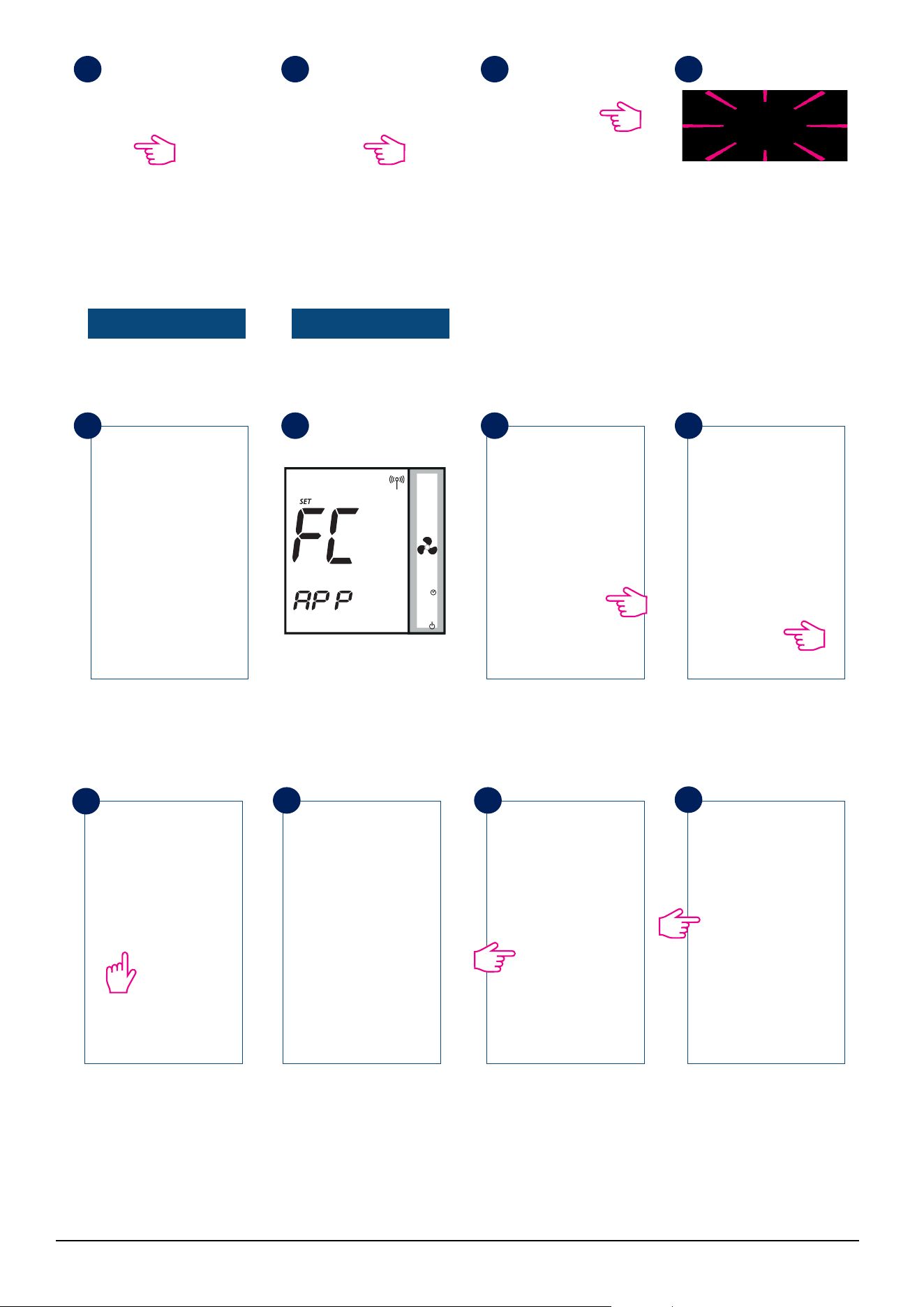
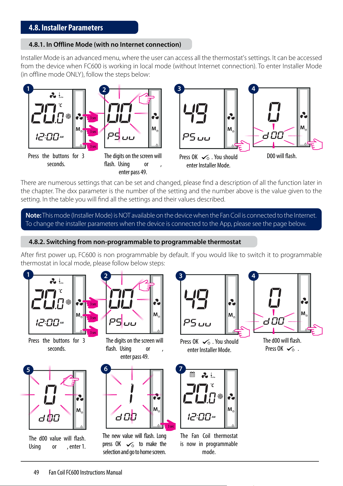
M
Press the buttons for 3
seconds.
M
Press OK
M
. You should
enter Installer Mode.
M
The digits on the screen will
ash. Using
M
or
M
,
enter pass 49.
M
D00 will ash.
Installer Mode is an advanced menu, where the user can access all the thermostat's settings. It can be accessed
from the device when FC600 is working in local mode (without Internet connection). To enter Installer Mode
(in offline mode ONLY), follow the steps below:
There are numerous settings that can be set and changed, please find a description of all the function later in
the chapter. The dxx parameter is the number of the setting and the number above is the value given to the
setting. In the table you will find all the settings and their values described.
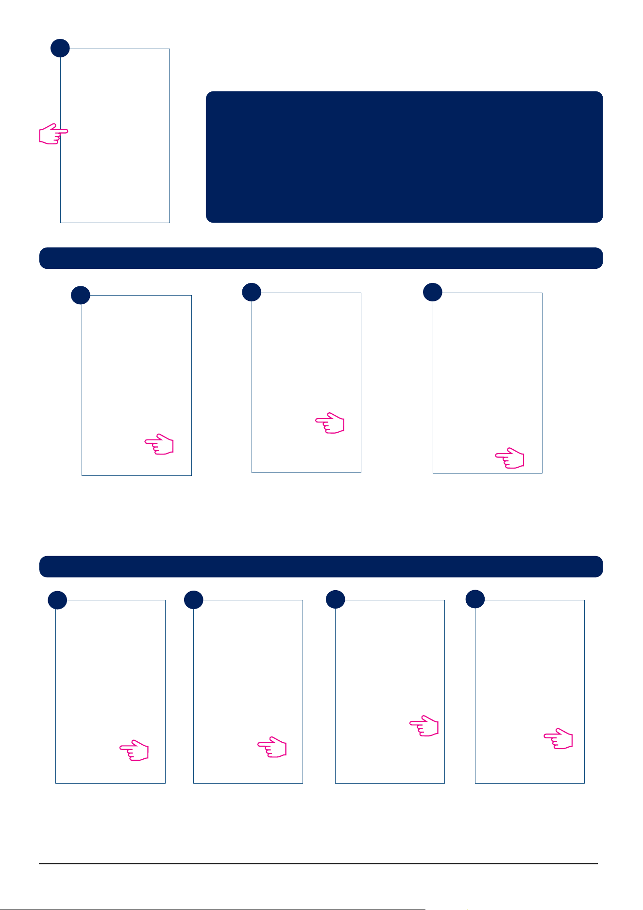
M
Press the buttons for 3
seconds.
M
Press OK
M
. You should
enter Installer Mode.
M
The digits on the screen will
ash. Using
M
or
M
,
enter pass 49.
M
The d00 will ash.
Press OK
M
.
M
The d00 value will ash.
Using
M
or
M
, enter 1.
The Fan Coil thermostat
is now in programmable
mode.
M
The new value will ash. Long
press OK
M
to make the
selection and go to home screen.
M
After first power up, FC600 is non programmable by default. If you would like to switch it to programmable
thermostat in local mode, please follow below steps:
Note: This mode (Installer Mode) is NOT available on the device when the Fan Coil is connected to the Internet.
To change the installer parameters when the device is connected to the App, please see the page below.
4.8. Installer Parameters
4.8.1. In Offline Mode (with no Internet connection)
4.8.2. Switching from non-programmable to programmable thermostat
1
1
5
2
6
3
7
4
2
3 4
3 sec
3 sec
3 sec
3 sec
3 sec
3 sec
3 sec
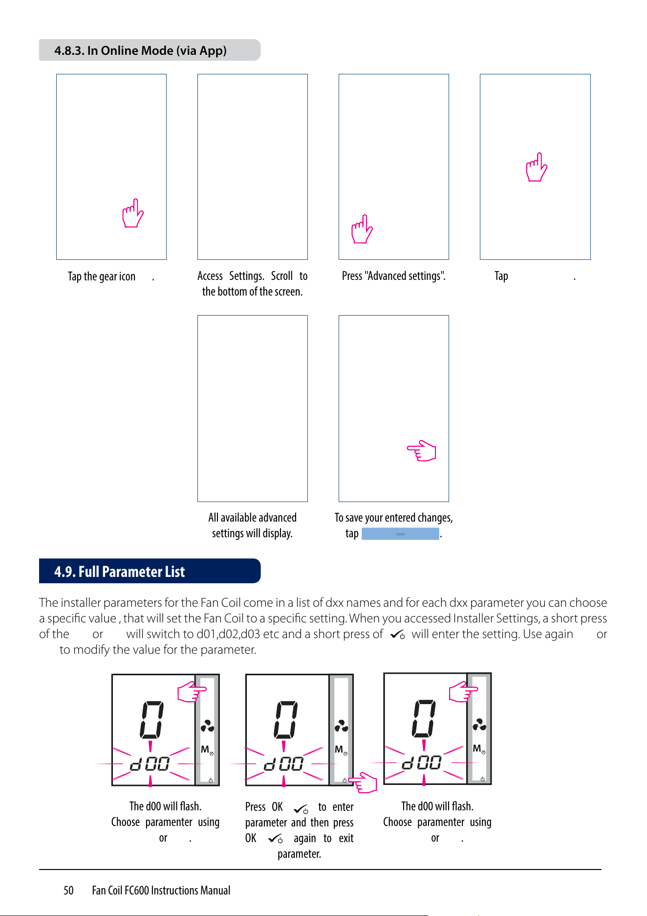
50 Fan Coil FC600 Instructions Manual
Tap the gear icon .
Access Settings. Scroll to
the bottom of the screen.
Press "Advanced settings". Tap .
All available advanced
settings will display.
To save your entered changes,
tap .
The installer parameters for the Fan Coil come in a list of dxx names and for each dxx parameter you can choose
a specific value , that will set the Fan Coil to a specific setting. When you accessed Installer Settings, a short press
of the
M
or
M
will switch to d01,d02,d03 etc and a short press of
M
will enter the setting. Use again
M
or
M
to modify the value for the parameter.
M
The d00 will ash.
Choose paramenter using
M
or
M
.
Press OK
M
to enter
parameter and then press
OK
M
again to exit
parameter.
M
The d00 will ash.
Choose paramenter using
M
or
M
.
M
4.9. Full Parameter List
4.8.3. In Online Mode (via App)
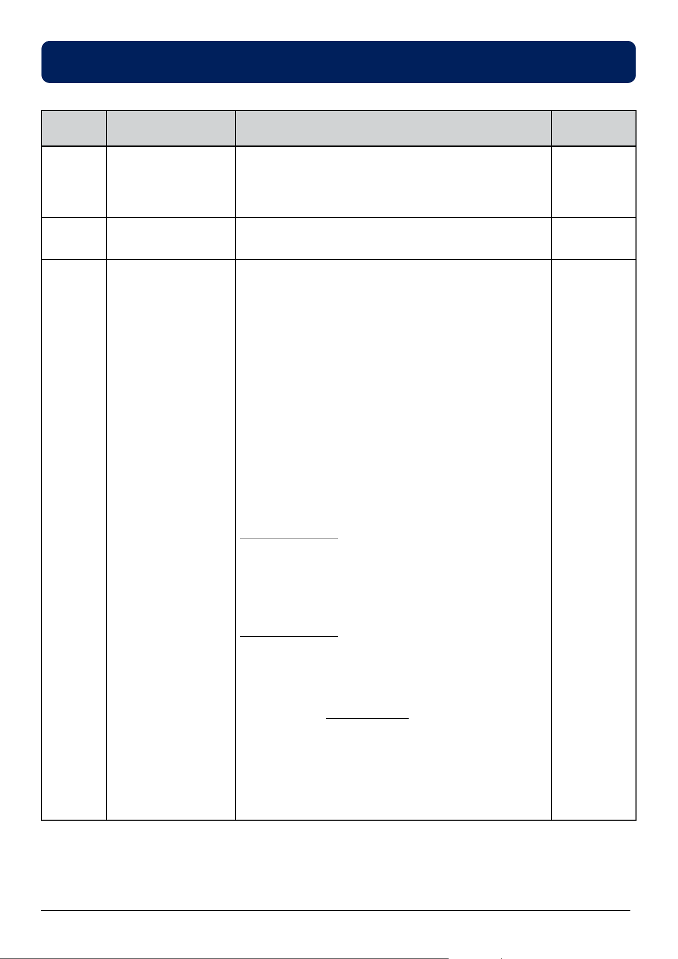
51 Fan Coil FC600 Instructions Manual
Parameter
number
Type of setting Description
Default
Values
d00 Type of thermostat 0 = Non-programmable - you cannot set schedules to
your thermostat. It can operate only in local mode
1 = Programmable - you can set schedules to your
thermostat
0
d01 Fancoil type
2 or 4 pipes
0 = 2 pipes
1 = 4 pipes
0
d02 S1/COM Terminal 0 = Manual - The user can change between Heating/
Cooling Modes only manually by pressing the Mode
button
1 = Heat/Cool changeover (HCCO) - the selection
between heating and cooling is made via the external
switch. User cannot select heating/cooling mode by
pressing the Mode button.
When
S1/COM contact is open = Heat mode
S1/COM contact is close = Cool mode
2 = Auto Heat/Cool Changeover - the switching
between heating and cooling is performed automatically.
User cannot select heating/cooling mode by pressing
the Mode button.
In a 2 pipe system
Procedure performed by the pipe sensor .
When the temperature on the pipe is low = cool mode
When the temperature on the pipe is high = heat mode.
The switching set point between heating and cooling is
determined by the d24 and d25 parameters.
In a 4 pipe system
The Heat/Cool changeover is performed automatically
by the internal sensor, using the function called "dead
zone".
3 = Auto Sens (for 2 pipes only). The function is available
only if there is a pipe sensor connected to the S1/com
terminal. The function will turn FAN OFF if pipe sensor's
temperature is <= d25 in heat mode or if the pipe sensor's
temperature is >= d24 in cool mode. User cannot select
heating/cooling mode by pressing the Mode button.
0
Note: During the installer mode, if no any button pressed, then FC600 should save the changes and go to
main menu in 15minutes.
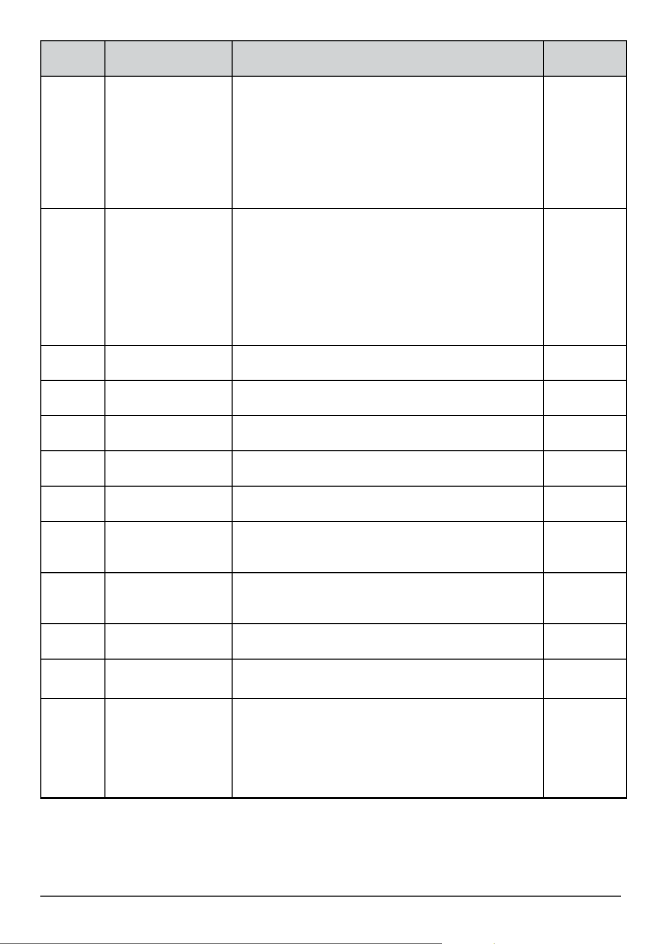
52 Fan Coil FC600 Instructions Manual
Parameter
number
Type of setting Description
Default
Values
d03 S2/COM terminals 0 = no function - ECO mode available via "Mode" button
1 = door - ECO mode (or STANDBY) is activated via
external free-volt switch:
- terminal S2/COM is open - normal mode
- terminal S2/COM is closed - ECO (STANDBY) mode
2 = SenS - external temperature sensor is connected.
Internal sensor is inactive - thermostat displays
temperature from external sensor.
0
d04 Heat and Cool mode
selection - This
parameter is available
only when d01 = 0
(2 pipe) and d02 =
0 or 2 ( S1-COM no
function, or pipe
sensor connected)
0 = Heating & Cooling available using MODE button
1 = Cooling ONLY (user can’t change mode using MODE
button)
2 = Heating ONLY (user can’t change mode using MODE
button)
1
d 05 Offset
This functions allows you to calibrate your displayed
temperature value. It can be adjusted from -3.0 ⁰C to +3.0⁰C
0⁰C
d06 Max heating setpoint From 5⁰C to 40 ⁰C 40 ⁰C
d07 Min heating setpoint From 5⁰C to 40 ⁰C 5⁰C
d08 Max cooling setpoint
temperature
From 5⁰C to 40 ⁰C 40 ⁰C
d09 Min cooling setpoint
temperature
From 5⁰C to 40 ⁰C 5⁰C
d10 ECO set point in
Heating mode
This setting is responsible for the ECO setpoint
temperature when the thermostat is in Heating mode.
Can be set to any value from 5⁰C to 40 ⁰C.
15⁰C
d11 ECO set point in
Cooling mode
This setting is responsible for the ECO setpoint
temperature when the thermostat is in Cooling mode.
Can be set to any value from 5⁰C to 40 ⁰C.
30⁰C
d12 Time zone From -13 to +13 +1
d13 DST – Day light
saving time
0 = Enabled
1 = Disabled
0
d14 Key lock function Use this function to enable/disable auto keylock function.
0 = manual - the user can lock the keys manually via
device or App.
1 = Auto (thermostat will lock the keys after 5 minutes
since last button press)
2 = Unlocked the user can't lock the keys.
0
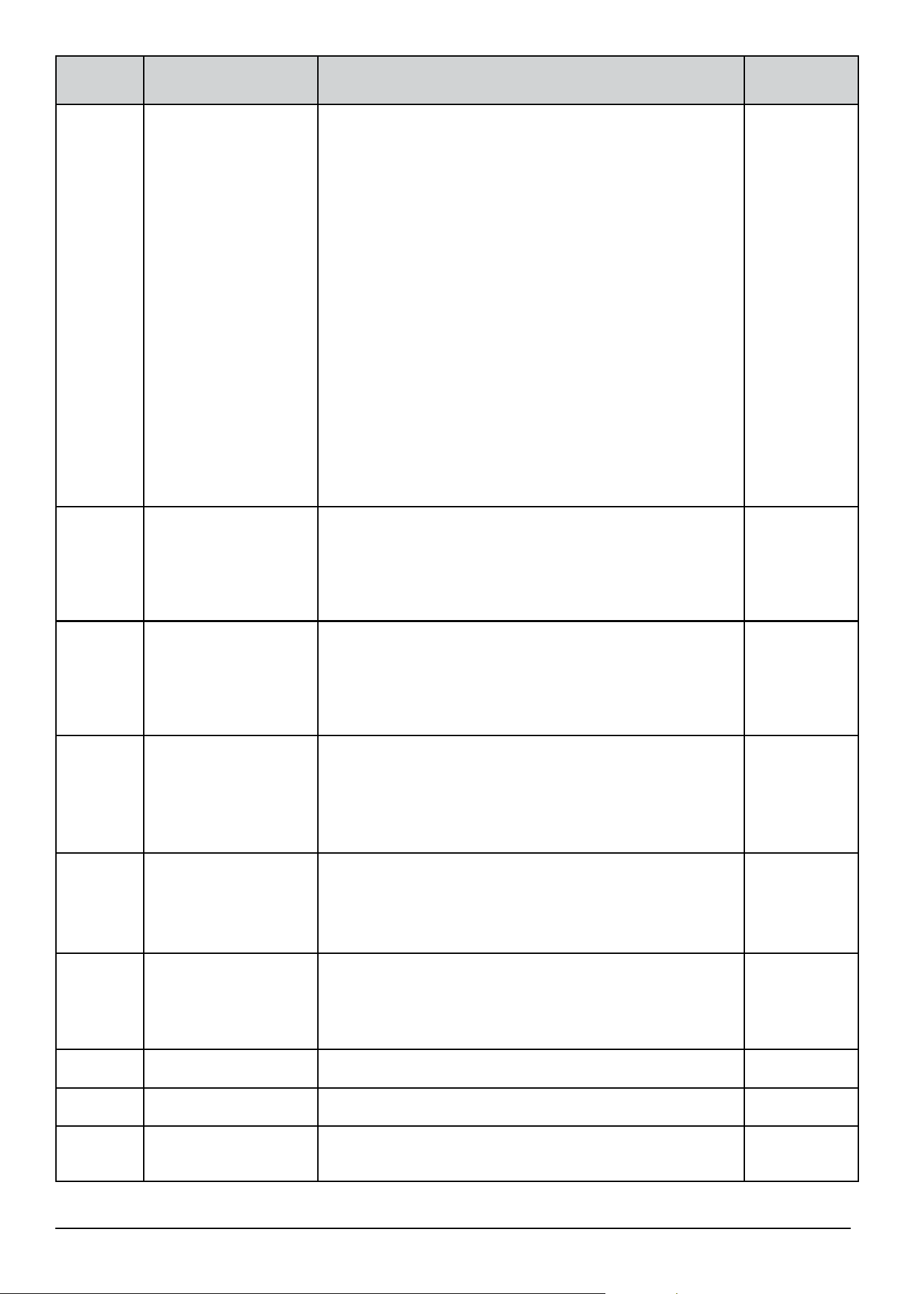
53 Fan Coil FC600 Instructions Manual
Parameter
number
Type of setting Description
Default
Values
d15 TPI/Span control 0 = TPI
1 = Span control
TPI - (Time Proportional and Integral alrgorithm) - fan
and valve control method, designed to provide the best
energy efficiency. This algorithm not only determines the
speed of the fan (depending on the difference between
the room temperature and the set temperature) but also
adapts its work according to repetitive home / office
temperature conditions to effectively and economically
manage the energy.
Span - room temperature control method to achieve
setpoint temperature in the fastest possible way by
changing the gears of the fan. With a large temperature
difference (between the setpoint and measured), the fan
operates at maximum speed. The closer to the setpoint,
the lower the fan speed.
0
d16 Set the control type
in modulation. This
parameter is available
only if we select TPI
algorithm, not SPAN
0 = Slow change environment
1 = Fast change environment
0
d17 Set the Span
control for heating
mode respectively
The range of span is 1 to 20 (0.1K to 2.0K)
Mean: 1=0.1K…20=2.0K
0.3K(This
parameter is
ignored if
TPI control is
selected)
d18 Set the Span
control for cooling
mode respectively
The range of span is 1 to 20 (0.1K to 2.0K)
Mean: 1=0.1K…20=2.0K
0.5K (This
parameter is
ignored if
TPI control is
selected)
d19 Set the minimum
turn off time for
heating mode
respectively
10 to 300 seconds 10
d20 Set the minimum
turn off time for
cooling mode
respectively
10 to 300 seconds 10
d21 TPI heat control CPH 3 – 12 on/off cycle per hour 6
d22 TPI cool control CPH 3 – 12 on/off cycle per hour 3
d23 Dead zone Comfort
mode (4 pipe only)
1.0 to 5.0K 2.0
54 Fan Coil FC600 Instructions Manual
Parameter
number
Type of setting Description
Default
Values
d24 Heat/cool
changeover cooling
switch-point Heat/
cool changeover
cooling switch-
point Heat/cool
changeover cooling
switch-point
The value of this parameter is used by the pipe
temperature sensor to switch to Heating mode. When
the temperature acquired by the sensor is above this
parameter's value, the thermostat will switch to heating
mode.
10⁰C
d25 Heat/cool
changeover heating
switch-point
The value of this parameter is used by the pipe
temperature sensor to switch to Cooling mode. When
the temperature acquired by the sensor is below this
parameter's value, the thermostat will switch to cooling
mode.
30⁰C
d26 S1 - COM input
position
0 = Normally open
1 = Normally close
0
d27 S2 - COM input
position
0 = Normally open
1 = Normally close
0
d28 Service filter The 'clean fan filter reminder' function counts the fan
operating hours. Is OFF or from 0.1 to 9.9 (9.9 means
9900hrs = 9.9*100)
Off
d29 Protection heating
set point
OFF or from 5⁰C to 40⁰C (d29 value can not higher than
d30)
8
d30 Protection cooling
set point
OFF or from 5⁰C to 40⁰C Off
d31 Temperature display
resolution
This setting allows you change the temperature display
resolution.
0 = 0.1⁰C
1 = 0.5⁰C
1
d32 Cooling start delay From 0 to 15 minutes 0
d33 Clock format 0 = 12h
1 = 24h
1
d34 ECO mode or
STANDBY mode.
When S2/COM
terminals are short –
thermostat will go to
ECO mode or
STANDBY mode.
0 = ECO mode
1 = STANDBY mode
For example when hotel card is in (occupancy sensor
indicates that person is in the room) – the thermostat
will go to ECO mode if you select ”0”, or go to STANDBY
model if you select ”1”(for details, please see below)
0
d35 OFFSET of the second
sensor connected do
S2/COM (parameter
available only when
d03 = 2)
From -3⁰C to +3⁰C 0⁰C
55 Fan Coil FC600 Instructions Manual
Parameter
number
Type of setting Description
Default
Values
d36 Status after power
breakdown
After the power is on, the thermostat will function in
0 = standby
1 = last configuration
0
d37 To allow user unlock
the keys
or NOT
1 = means user can unlock by pressing and
0 = means user can NOT unlock by pressing and
If d37=0, user can lock/unlock the keys, only through the
App.
0
d38 Manual Fan Speed
Operation
0 = Fan always on (doesn’t matter if the Fan Coil is calling
or not for heating or cooling)
1 = FAN works on the speed set manually, only when the
Fan Coil is calling for heating or cool
1
d39 FAN turning ON delay 0 seconds to 30 minutes 0
d40
FAN turning OFF delay
0 seconds to 30 minutes 0
d41
Valve control when
FAN is manually OFF
0 – (default) no valve control when fan is MANUALLY off
1 – still use valve control when fan is MANUALLY off
d42 Fan control available
only in COOLING
mode
* connection diagram
on the next page
0 - fan control is available in all modes
1 - fan control is available ONLY in COOLING mode
0
d43 Allow to adjust
setpoint in device
when buttons locked
0 - No
1 - Yes
0
Note: Parameter d01 settings CANNOT be changed in the installer menu, neither on the device nor in
the application. It depends on the initial configuration of the thermostat and can only be changed after a
device reset (i.e. after restoring factory settings). Some parameters will be visible / invisible depending on
the setting of main parameter d01 (fan coil type: 0 = 2-pipe; 1 = 4-pipe).
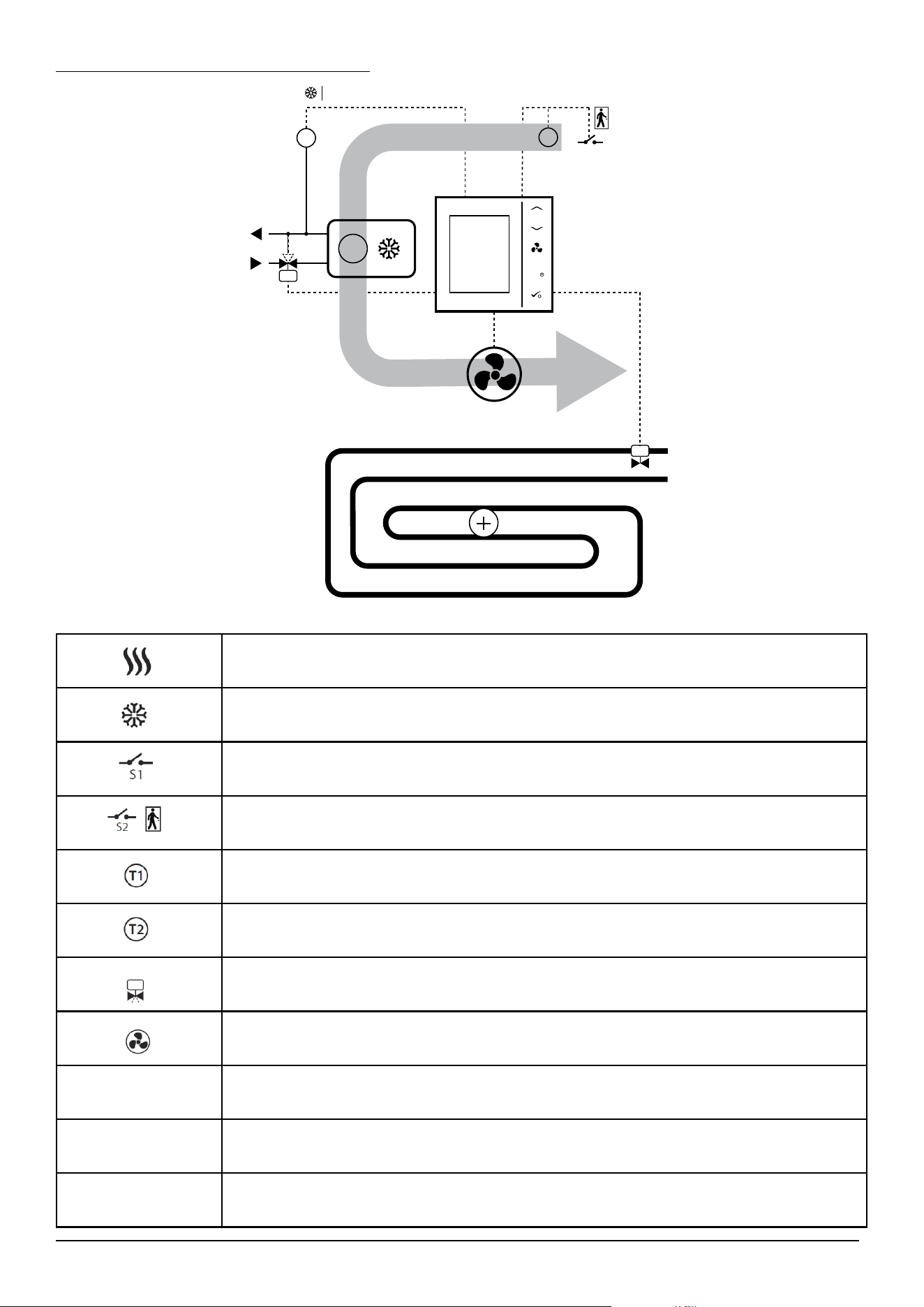
56 Fan Coil FC600 Instructions Manual
Connection diagram for parameter d42
WENTYLATOR
STOP/START
OGRZEWANIE PODŁOGOWE
M
V2 V1
S1 S2
S2
F1, F2, F3
T1
LUB
T2
−
POWIETRZE
AIR
OR
FAN
UNDERFLOOR HEATING
Heating mode
Cooling mode
External switch (ON/OFF) (heat/cool changeover)
External switch (ON/OFF) (e.g. an occupancy sensor, launching ECO or Standby mode)
Pipe temperature sensor (allows the fan to be working or not)
Air temperature sensor or external room temp. sensor (FC600 will display temperature
from the sensor connected to T2. Internal temperature sensor will be ignored)
Motorized valve / actuator
3-gear speed fan
Heating device
Cooling device
Heating or cooling device (2-pipe system only)
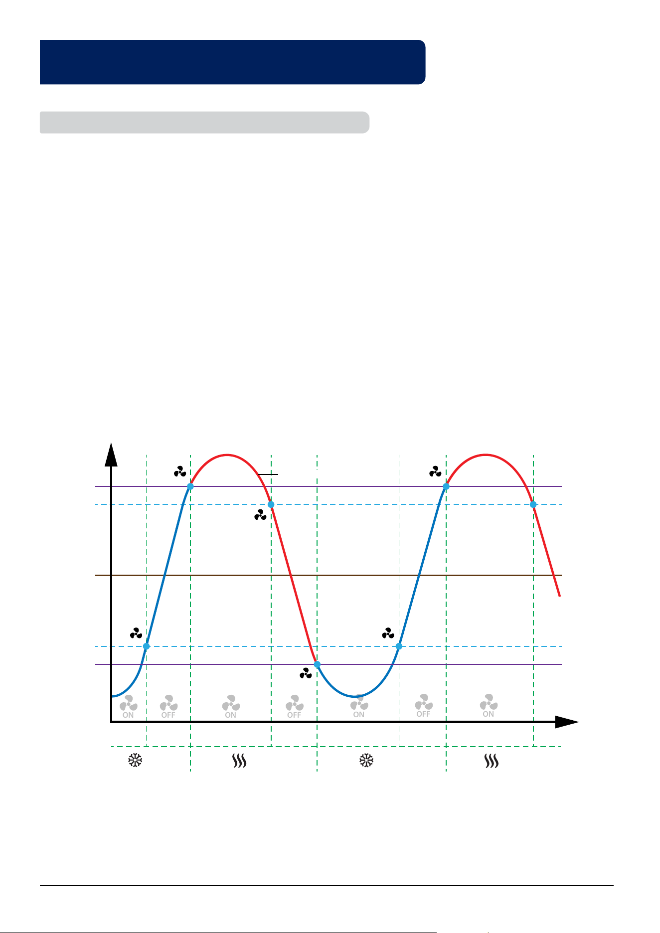
57 Fan Coil FC600 Instructions Manual
4.10. Fan and valve operation (V1) including pipe sensor in a
2-pipe system with the use of "d24" and "d25" parameters
The following diagram explains the principle of switching between heating and cooling as well as the operating
conditions for the fan and valve (V1):
I stage - Valve V1 opens, the thermostat works in cooling mode. The temperature of the pipe increases to the
value from parameter "d24" + 2 ° C and at this moment it turns off the fan.
Stage II - Valve V1 opens, the temperature of the pipe increases to the value from parameter "d25", the thermostat
switches from cooling to heating. Then the fan gets permission to work.
Stage III - Valve V1 opens, the thermostat works in heating mode. The temperature of the pipe drops to the
value from parameter "d25" - 2 ° C, and at this moment it turns off the fan.
IV stage - Valve V1 opens, the temperature of the pipe drops to the value from parameter "d24", the thermostat
switches from heating to cooling. Then the fan gets permission to work.
V stage - Valve V1 opens, the thermostat works in cooling mode. The temperature of the pipe increases to the
value from the parameter "d24" + 2 ° C and at this moment it turns off the fan (this is the same as stage I)
Stage VI - the same as stage II
4.10.1. Fan operation in heating and cooling mode
M
I
t [°C]
T [s]
d24 = 10°C
d24 +2°C
d25 -2°C
d25 = 30°C
pipe temperature
setpoint
temperature =
20°C
Cooling
Mode
Cooling
Mode
Heating
Mode
Heating
Mode
II III IV V VI
STOP
STOP
ON
ON
ON
ON
OFF
OFF
OFF
STOP
START START
START
M
M
M
M
M
M
M
M
M
M
M
M
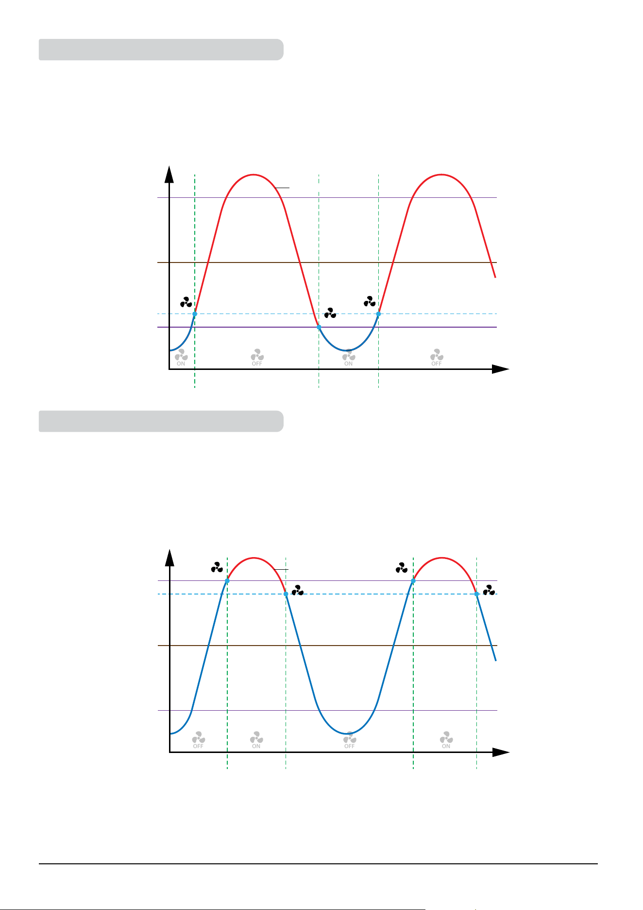
58 Fan Coil FC600 Instructions Manual
If FC600 is in cooling mode and has the task of cooling the room, the valve V1 opens. The fan will start only
when the pipe reaches the temperature below the "d24" value. If the temperature of the pipe will increase by
2°C above the parameter "d24", the fan will be switched off and the valve will still be open. FC600 waits until
temperature of the pipe will drop below the "d24" parameter and only then starts the fan. This is useful if FC600
controls the water fan coils (coolers), which are not to be operated in the winter.
If FC600 is in heating mode and has the task of heating the room, the valve V1 opens. The fan will start only
when the pipe reaches the temperature of the higher value of the parameter "d25". If the temperature of the
pipe drops below 2°C below parameter "d25", the fan will be switched off and the valve will still be open. FC600
expects an upward mode (above parameter "d25") and only then starts the fan. Such a solution is helpful if the
regulator controls the water fan coils (heaters), which are not to be operated in the summer.
Note: When the pipe temperature is too low (in heating mode) or too high (in cooling mode) - the sensor icon
and digit "1" will flash on the LCD. When the pipe temperature is right, fan will start-up and the icons on the LCD
will be permanently lit (it will not blink).
4.10.2. Fan operation in cooling mode
4.10.3. Fan operation in heating mode
I II III
t [°C]
T [s]
d24 = 10°C
d24 +2°C
d25 - parameter in
Cooling Mode
pipe temperature
setpoint temperature
= 20°C
ON
ON
OFF
OFF
M
M
M
M
STOP
STOP
M
M
START
M
OFF
M
I
t [°C]
T [s]
d25 = 30°C
d25 -2°C
d24 - parameter in
Heating Mode
pipe temperature
setpoint temperature
= 20°C
II II
ON
ON
M
M
OFF
M
START
START
M
M
STOP
STOP
M
M

59 Fan Coil FC600 Instructions Manual
If you want to add the FC to the UGE600 after you set it up, you need to use the 55 code, and than you select
UG YES, and then you confirm PAIR to start joining the UG. On the App you should see all the settings which
have been already done in the past, when you configured the FC600 without the UG. Please see the detailed
procedure as shown. Make sure your UG is connected to the system and you have the App installed.
M
Press the buttons for 3
seconds.
M
Press OK
M
.
M
The digits on the screen will
ash. Using
M
or
M
,
enter pass 55.
M
Press OK
M
.
M
At this point you should
go to the App in order to
congure your Fan Coil.
Make sure that your Universal Gateway is added to the App. The
led of the Gateway should be steady blue. Once you have that
installed, go to your Fan Coil and begin paring it with the UG and
adding it to the App.
To begin the pairing process the gateway should be plugged into the power source and connected to the
Internet. Also, make sure that the UG is added to your Salus Smart Home App. For the installation of the Universal
Gateway, please refer to the UG600/UGE600 manual on salus-manuals.com
Now go to the App. Tap
menu icon .
4.11. Switching from oine to online mode
1 2
5 64
3
The
antenna sign
will appear in
the corner of the
screen.
3 sec
3 sec
3 sec
60 Fan Coil FC600 Instructions Manual
Tap Settings. Tap Setup Equipment. Tap Scan for equipment.
When new equipment is
being added, the UG should
ash red.
The Fan Coil should appear
on screen.
Select device and tap
Connect equipment.
Rename your device and
tap Next.
M
The Fan Coil will go
automatically into FC App
screen.
Now, tap Finish to
complete the setup.
The thermostat tile appears
on the dashboard.
7
11
15
8
12
9
13 14
16
10
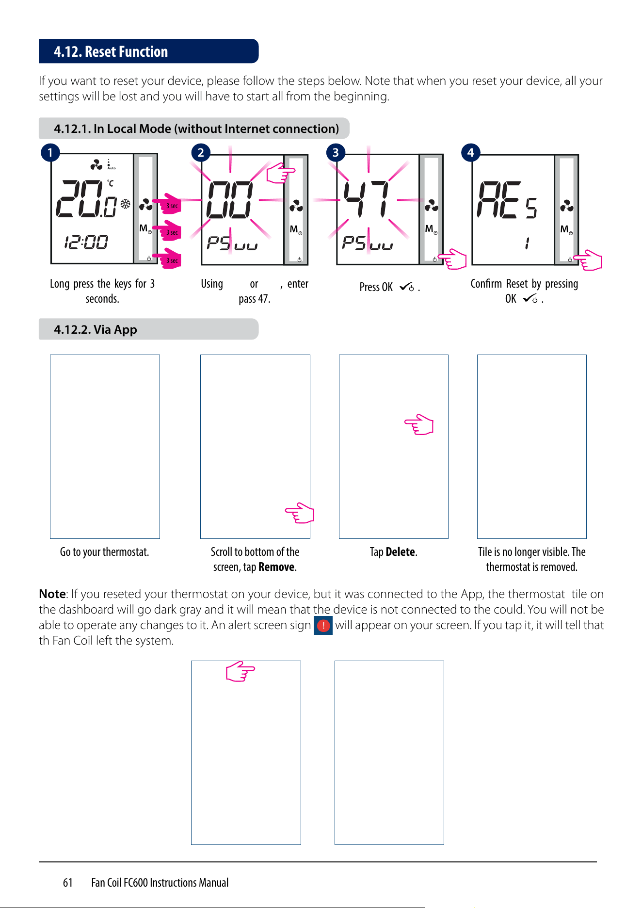
61 Fan Coil FC600 Instructions Manual
If you want to reset your device, please follow the steps below. Note that when you reset your device, all your
settings will be lost and you will have to start all from the beginning.
M
M
M
Long press the keys for 3
seconds.
Using
M
or
M
, enter
pass 47.
Press OK
M
.
M
Conrm Reset by pressing
OK
M
.
Tile is no longer visible. The
thermostat is removed.
Go to your thermostat. Scroll to bottom of the
screen, tap Remove.
Tap Delete.
Note: If you reseted your thermostat on your device, but it was connected to the App, the thermostat tile on
the dashboard will go dark gray and it will mean that the device is not connected to the could. You will not be
able to operate any changes to it. An alert screen sign will appear on your screen. If you tap it, it will tell that
th Fan Coil left the system.
4.12. Reset Function
4.12.1. In Local Mode (without Internet connection)
4.12.2. Via App
1 42 3
3 sec
3 sec
3 sec
62 Fan Coil FC600 Instructions Manual
The FC600 Fan Coil requires no special maintenance. Periodically, the outer casing can be wiped clean using
a dry cloth (please DO NOT use solvents, polishes, detergents or abrasive cleaners, as these can damage the
thermostat). There are no user serviceable parts within the unit; any servicing or repairs could only be carried
out by Salus Controls or their appointed agents.
Product Specication
Model: FC600
AC power supply 230Vac +10% -15% 50Hz
Temperature Sensing specications
Temperature Sensors Air sensor ( indoor ) + External-sensor (optional)
Unit of temperature measurement °C
Indoor temp sensor measuring range 0°C –45°C
Indoor temp sensor display range 0°C –45°C
Indoor temp display resolution 0.5°C or 0.1°C (selectable)
Indoor temp set point range 5°C - 40°C
Indoor Temperature accuracy offset range From -3,0 to +3,0 in 0,5 steps
Frost protection point Yes
Overheat protection Yes
Temperature sampling duration Every 15 seconds
Multifunctional input S1-M/S2-M
Temperature sensor input Type NTC 10 kOhm B 25/50 = 3950K, R 25 = 10.000KOhm
Temperature range 0…50°C
Clock display format 12 / 24 hour format
Program Setting
Program 5+2 / 7 individual days / all 7 days same
Temporary & Permanent Override Yes
Memory
Non-volatile memory MCU flash store clock and all user settings
Backup power during power blackout Uhe ideal position to locate the RT310 thermostat is about
1.5m above floor level, in a location where the thermostat
is accessible, reasonably lit and free from extremes of tem-
perature and draughts. Do not mount the thermostat on an
outside wall, above a radiator or in a location where it may be
subjected to direct sunlight.p to 17hrs
Dust and water proof level IP30
Operating environment
Operating temperature 0°C - 50°C
Storage temperature -25°C - 60°C
Relative humidity ( non-condensed ) <95% r.h.
4.14. Technical Specication
4.13. Cleaning and Maintenance
63 Fan Coil FC600 Instructions Manual
SALUS Controls warrants that this product will be free from any defect in materials or workmanship, and shall
perform in accordance with its specification, for a period of five years from the date of installation. SALUS
Controls sole liability for breach of this warranty will be (at its option) to repair or replace the defective product.
Customer Name: ...................................................................................................................
Customer Address: ...............................................................................................................
......................................................................... Post Code: ....................................................
Tel No: ..................................................... Email: ...................................................................
Company Name: ...................................................................................................................
Tel No: ....................................................... Email: .................................................................
Installation Date: ..................................................................................................................
Installer Name: ......................................................................................................................
Installer Signature: ...............................................................................................................
4.15. Warranty
64 Fan Coil FC600 Instructions Manual
NOTES

IMPORTER:
SALUS Controls Plc
Units 8-10 Northfield Business Park
Forge Way, Parkgate
Rotherham
S60 1SD
United Kingdom
DISTRIBUTOR OF SALUS CONTROLS:
QL CONTROLS Sp. z o.o., Sp. k.
Rolna 4,
43-262 Kobielice,
Poland
www.salus-controls.com
SALUS Controls is a member of the Computime Group.
Maintaining a policy of continuous product development SALUS Controls plc reserve the right to change
specification, design and materials of products listed in this brochure without prior notice.
Issued: VII 2020
Version: 1