
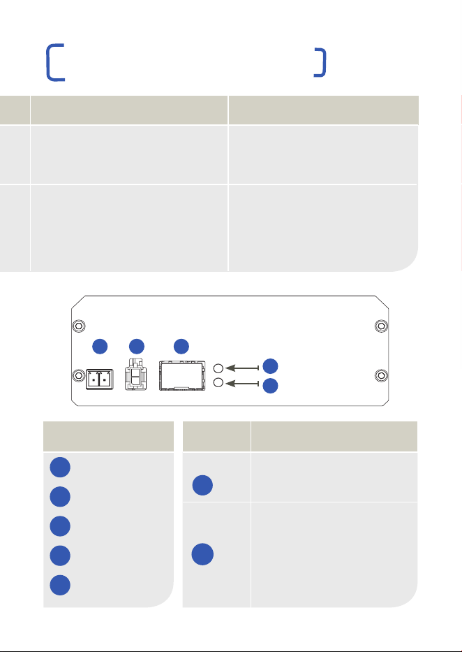
SFP LED OPERATION
Top Red = No module inserted
Green = Device inserted
Bottom Off = No module inserted
Red = No device link
detected
Green = Link detected
4
5
FUNCTIONS
1 57V DC Power
2 57V DC Power
3 SFP Module
4 SFP Top LED
5 SFP Bottom LED
VHW-HWPS-B8
QUICK START GUIDE
8 PORT EOC BASE WITH POE PLUS
HIGHWIRE
POWERSTAR BASE 8
05 0706
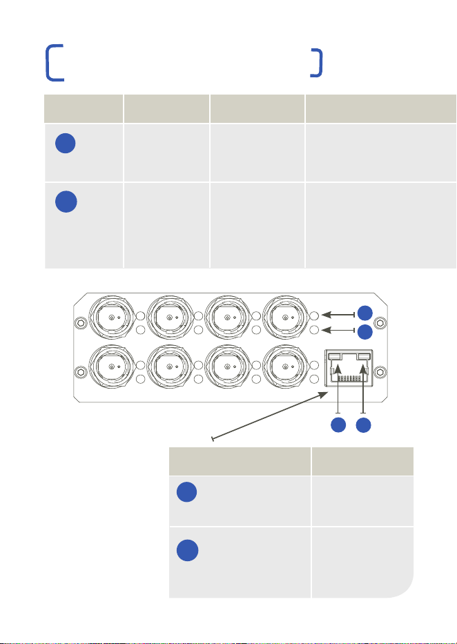
8 x BNC connectors. Connect to any 75 Ohm coaxial cable. 57V Power Supply Options : Connect to either option 1 OR option 2
POE LED
COAX LINK
ACTIVITY
COAX POE
(Power)
FUNCTION
Coax data
connection
POE over
coax status
GREEN
Blink = No link to camera
On = 100Base-TX to camera
Flash = 100Base-TX activity
On = Device detected
ORANGE
Blink = 10Base-T link to camera
Flash = 10Base-T activity
On = Approaching power limit
Flash = Short circuit. Check
for cable faults or incompatible
equipment
RED
On = Data rate <100%
Cable distance at limit
On = Power limit reached
Flash = POE discontinued
due to overload
321
4
5
A
B
ETHERNET LED FUNCTION
RJ45 Yellow On = link
Blink = activity
RJ45 Green On = Power on
C
D
A
B
C
D
LOCATION
CONNECTIONS AND LEDS
CONNECTIONS AND LEDS
PRODUCT DIMENSIONS
© Veracity UK Ltd 2016 QSGV1.2 UK
HIGHWIRE POWERSTAR BASE 8 is a trademark of Veracity UK Ltd
RoHS
110 mm
40 mm
154 mm
173 mm

01 0302 04
OVERVIEW
HIGHWIRE Powerstar products are designed to enable the
transmission of standard Ethernet and POE (Power over
Ethernet) over coaxial cables originally installed for analogue
video transmission for CCTV.
These devices can be classed as adaptors or media converters.
They are typically used where analogue CCTV cameras are being
replaced with modern digital network cameras, known as “IP
cameras”. This permits IP cameras to be installed without having
to replace cable and re-wire buildings.
In most CCTV installations, multiple coaxial cable runs will come
together at a central point (e.g. equipment room or control room).
The Base units are located here. Whilst multiple single-channel
HIGHWIRE Powerstar Base units can be used for multiple channels,
it is more cost-effective to provide integrated multi-channel units with
an internal Ethernet switch, allowing more than one coaxial cable to
be connected into the network system per HIGHWIRE device.
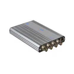
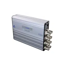
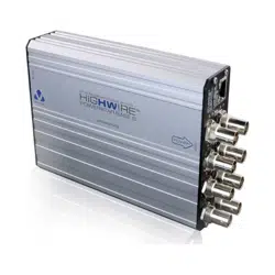
HIGHWIRE Powerstar Base 8 provides eight coaxial cable
connections. The Base unit has a single standard RJ45 Gigabit
Ethernet port to allow connection to a main network switch.
An SFP socket is also provided to allow a fibre network connection
if required by the application.
All HIGHWIRE Powerstar Base 8 units must be powered through a
DC power connector which is designed for a maximum of 6A at 57V
DC.
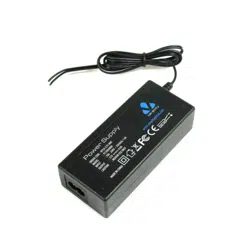
Either the 1500mA or 8800mA Veracity 57V DC Power Supplies are
recommended. The latter allows up to 25W of POE to be delivered to
each IP camera connected.
| Connect the coax cable for 1-8 cameras or POE / non-POE
devices to the BNC connectors of the HIGHWIRE Powerstar
Base 8 at the switch end.
| Connect the coax cable to the BNC connectors of the HIGHWIRE
Powerstar Camera units at the camera end.
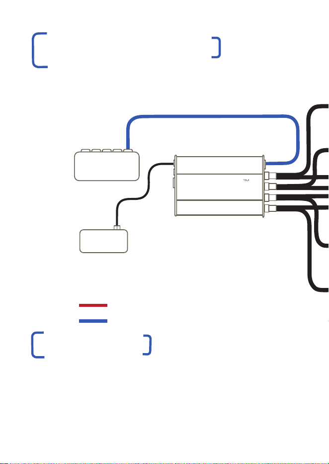
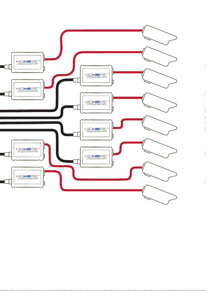
APPLICATION DIAGRAM
ETHERNET OVER COAX
| Connect 1-8 cameras or POE / non-POE devices to the RJ45
ports of the HIGHWIRE Powerstar Camera units at the camera end.
| Connect the HIGHWIRE Powerstar Base 8 unit to a network switch.
| Connect the HIGHWIRE Powerstar BASE 8 unit to your chosen
57V Veracity Power Supply. The installation is complete.
INSTALL ATION
TECHNICAL SPECIFICATION
Power Input PSU 57V DC up to 6A via a 2 pin detachable
screw terminal (supplied) or a 2 pin Micro-Fit
power connector
EOC Power Output Max 25W per port (POE Plus)
Ethernet Interface Connector type RJ45 Ethernet Gigabit port to
allow connection to a main network switch
HIGHWIRE Interface Connector type BNC 75 Ohm
Range Up to 300m on RG59, 500m on RG11
Bandwith 200Mbps (total up + down)
Dimensions 173 x 110 x 40mm (6.8 x 4.3 x 1.6in) inc BNCs
Weight 572g (20.2oz) unpackaged
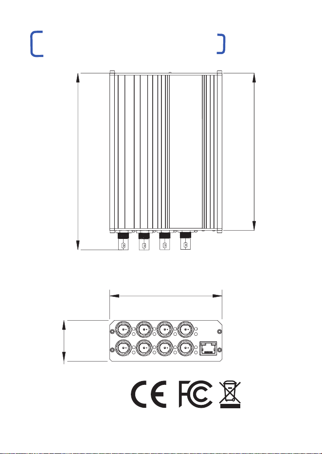
Compliance RoHS, CE, FCC, REACH
Temperature Operating 0°C to 40°C (32°F to 104°F)
Relative Humidity 85% non condensing
Installation The unit is supplied in an aluminium chassis with
rubber feet. It may be used as a stand-alone or
may be rack mounted via available accessories.
IMPORTANT SAFET Y NOTES
| This equipment is designed for indoor use only.
| If the equipment is used in a manner not specified by the
manufacturer, the protection provided by the equipment may
be impaired.
| Contact details for Sales and Technical Support can be found
on the Company website: www.veracityglobal.com
ETHERNET
UP TO 300M ON RG59 / 500M ON RG11
VHW-HWPS-C
ETHERNET & POE
COAX
VHW-HWPS-B8
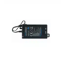
VPSU-57V-1500
OR VPSU-57V-1U
POWER
ETHERNET & POE
ETHERNET DATA ONLY
HIGHWIRE
POWERSTAR
BASE 8
POWER
SUPPLY
NETWORK
SWITCH
CAMERA
CAMERA
CAMERA
CAMERA
CAMERA
CAMERA
CAMERA
CAMERA
01 0302 04
OVERVIEW
HIGHWIRE Powerstar products are designed to enable the
transmission of standard Ethernet and POE (Power over
Ethernet) over coaxial cables originally installed for analogue
video transmission for CCTV.
These devices can be classed as adaptors or media converters.
They are typically used where analogue CCTV cameras are being
replaced with modern digital network cameras, known as “IP
cameras”. This permits IP cameras to be installed without having
to replace cable and re-wire buildings.
In most CCTV installations, multiple coaxial cable runs will come
together at a central point (e.g. equipment room or control room).
The Base units are located here. Whilst multiple single-channel
HIGHWIRE Powerstar Base units can be used for multiple channels,
it is more cost-effective to provide integrated multi-channel units with
an internal Ethernet switch, allowing more than one coaxial cable to
be connected into the network system per HIGHWIRE device.
HIGHWIRE Powerstar Base 8 provides eight coaxial cable
connections. The Base unit has a single standard RJ45 Gigabit
Ethernet port to allow connection to a main network switch.
An SFP socket is also provided to allow a fibre network connection
if required by the application.
All HIGHWIRE Powerstar Base 8 units must be powered through a
DC power connector which is designed for a maximum of 6A at 57V
DC.
Either the 1500mA or 8800mA Veracity 57V DC Power Supplies are
recommended. The latter allows up to 25W of POE to be delivered to
each IP camera connected.
| Connect the coax cable for 1-8 cameras or POE / non-POE
devices to the BNC connectors of the HIGHWIRE Powerstar
Base 8 at the switch end.
| Connect the coax cable to the BNC connectors of the HIGHWIRE
Powerstar Camera units at the camera end.
APPLICATION DIAGRAM
ETHERNET OVER COAX
| Connect 1-8 cameras or POE / non-POE devices to the RJ45
ports of the HIGHWIRE Powerstar Camera units at the camera end.
| Connect the HIGHWIRE Powerstar Base 8 unit to a network switch.
| Connect the HIGHWIRE Powerstar BASE 8 unit to your chosen
57V Veracity Power Supply. The installation is complete.
INSTALL ATION
TECHNICAL SPECIFICATION
Power Input PSU 57V DC up to 6A via a 2 pin detachable
screw terminal (supplied) or a 2 pin Micro-Fit
power connector
EOC Power Output Max 25W per port (POE Plus)
Ethernet Interface Connector type RJ45 Ethernet Gigabit port to
allow connection to a main network switch
HIGHWIRE Interface Connector type BNC 75 Ohm
Range Up to 300m on RG59, 500m on RG11
Bandwith 200Mbps (total up + down)
Dimensions 173 x 110 x 40mm (6.8 x 4.3 x 1.6in) inc BNCs
Weight 572g (20.2oz) unpackaged
Compliance RoHS, CE, FCC, REACH
Temperature Operating 0°C to 40°C (32°F to 104°F)
Relative Humidity 85% non condensing
Installation The unit is supplied in an aluminium chassis with
rubber feet. It may be used as a stand-alone or
may be rack mounted via available accessories.
IMPORTANT SAFET Y NOTES
| This equipment is designed for indoor use only.
| If the equipment is used in a manner not specified by the
manufacturer, the protection provided by the equipment may
be impaired.
| Contact details for Sales and Technical Support can be found
on the Company website: www.veracityglobal.com
ETHERNET
UP TO 300M ON RG59 / 500M ON RG11
VHW-HWPS-C
ETHERNET & POE
COAX
VHW-HWPS-B8
VPSU-57V-1500
OR VPSU-57V-1U
POWER
ETHERNET & POE
ETHERNET DATA ONLY
HIGHWIRE
POWERSTAR
BASE 8
POWER
SUPPLY
NETWORK
SWITCH
CAMERA
CAMERA
CAMERA
CAMERA
CAMERA
CAMERA
CAMERA
CAMERA
SFP LED OPERATION
Top Red = No module inserted
Green = Device inserted
Bottom Off = No module inserted
Red = No device link
detected
Green = Link detected
4
5
FUNCTIONS
1 57V DC Power
2 57V DC Power
3 SFP Module
4 SFP Top LED
5 SFP Bottom LED
VHW-HWPS-B8
QUICK START GUIDE
8 PORT EOC BASE WITH POE PLUS
HIGHWIRE
POWERSTAR BASE 8
05 0706
8 x BNC connectors. Connect to any 75 Ohm coaxial cable. 57V Power Supply Options : Connect to either option 1 OR option 2
POE LED
COAX LINK
ACTIVITY
COAX POE
(Power)
FUNCTION
Coax data
connection
POE over
coax status
GREEN
Blink = No link to camera
On = 100Base-TX to camera
Flash = 100Base-TX activity
On = Device detected
ORANGE
Blink = 10Base-T link to camera
Flash = 10Base-T activity
On = Approaching power limit
Flash = Short circuit. Check
for cable faults or incompatible
equipment
RED
On = Data rate <100%
Cable distance at limit
On = Power limit reached
Flash = POE discontinued
due to overload
321
4
5
A
B
ETHERNET LED FUNCTION
RJ45 Yellow On = link
Blink = activity
RJ45 Green On = Power on
C
D
A
B
C
D
LOCATION
CONNECTIONS AND LEDS
CONNECTIONS AND LEDS
PRODUCT DIMENSIONS
© Veracity UK Ltd 2016 QSGV1.2 UK
HIGHWIRE POWERSTAR BASE 8 is a trademark of Veracity UK Ltd
RoHS
110 mm
40 mm
154 mm
173 mm