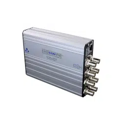

VHW-HWPS-B8-LL
QUICKSTART ADDENDUM
TAMPER-PROOF ETHERNET AND POE OVER COAX
HIGHWIRE
POWERSTAR BASE 8
LINKLOCK
05 0706
SFP LED OPERATION
Top Red = No module inserted
Green = Device inserted
Bottom Off = No module inserted
Red = No device link
detected
Green = Link detected
4
5
8 x BNC connectors. Connect to any 75 ohm coaxial cable.
POE LED
COAX LINK
ACTIVITY
COAX POE
(Power)
FUNCTION
Coax data
connection
POE over
coax status
GREEN
Blink = No link to camera
On = 100Base-TX to camera
Flash = 100Base-TX activity
On = Device detected
ORANGE
Blink = 10Base-T link to camera
Flash = 10Base-T activity
On = Approaching power limit
Flash = Short circuit. Check
for cable faults or incompatible
equipment
RED
On = Data rate <100%
Cable distance at limit
Flash = LINKLOCK protected
On = Power limit reached
Flash = LINKLOCK protected
mode. To Arm the device the
ARM/RESET input should be
triggered.
ETHERNET LED FUNCTION
RJ45 Yellow On = Link
Blink = Activity
RJ45 Green On = Power on
A
B
C
D
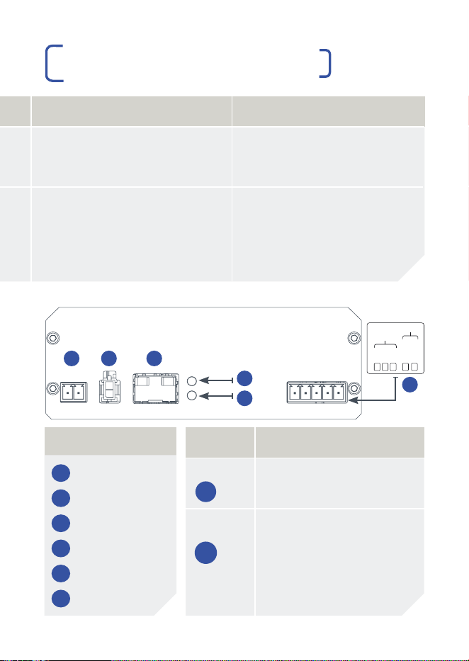
LOCATION
CONNECTIONS AND LEDS
CONNECTIONS AND LEDS
PRODUCT DIMENSIONS
LED
A
and
B
will both flash Red when in LINKLOCK protected
mode. To Arm the device the ARM/RESET input should be triggered.
A
L
A
R
M
O
U
T
P
U
T
ARM/
RESET
NO
COM
NC
INPUT
57V Power Supply Options | Connect to either option 1 OR option 2
321
4
5
A
B
C
D
110 mm
40 mm
154 mm
173 mm
FUNCTIONS
1 57V DC Power
2 57V DC Power
3 SFP Module
4 SFP Top LED
5 SFP Bottom LED
6 LINKLOCK Pins
6
®
Veracity UK Ltd Prestwick International Aerospace Park, 4 Dow Road, Prestwick, KA9 2TU. UK
Veracity’s Authorised Representative in the EU (as required by EU law for CE marked goods)
is: Comply Express Unipessoal Limitada, StartUp Madeira, EV141, Campus da Penteada,
9020 105 Funchal, Portugal.
© Veracity UK Ltd 2022 ADNM DV1.2 EN HIGHWIRE Powerstar Base 8 Linklock is a registered trademark of
Veracity UK Ltd
RoHS

LINKLOCK™ OVERVIEW
The LINKLOCK variant of HIGHWIRE Powerstar Base 4 and Base 8
units adds tamper-detection to the signal cabling, starting from the
coax output at the Base unit.
Any tampering with the coax cable, the HIGHWIRE Camera device
or the network cable between it and the IP camera, including
disconnection, “tapping in” or any other interference with the normal
signal transmission will cause an immediate shutdown of signal and
power from the Base device on that channel.
ARM/RESET INPUT
| Clears the LINKLOCK protection and flashing LEDs, resets and
arms the device.
| Triggered by the two INPUT terminals becoming electrically
connected, typically using clean relay contacts or a push button.
| Contacts may remain connected or only be connected
momentarily, however connecting them momentarily is
best practice.
ALARM OUTPUTS
| NO = Normally Open, COM = Common, NC = Normally Closed
| NC and COM are connected during normal operation
| NO and COM are connected to signal an alarm when
LINKLOCK protection is triggered or if there is no power
| The HIGHWIRE will go into LINKLOCK protected mode on power
up and must be armed before use (this prevents tampering by
power-cycling the units).
| Once the ARM/RESET contact has triggered, the unit will operate
as normal and deliver power and data connections to the remote
HIGHWIRE unit.
| Cables may be connected and disconnected initially as required,
to allow the IP camera installation to be completed.
| Once an Ethernet connection to the camera has been established
for 3 minutes, the LINKLOCK protection is armed.
| Any cable disconnection or tampering after this time will trigger
the LINKLOCK protected mode and disable the data and power.
| The connection can be restored again by closing the IN
contacts as before.
IMPORTANT SAFETY NOTES
| This equipment is designed for indoor use only.
| If the equipment is used in a manner not specified by the
manufacturer, the protection provided by the equipment may
be impaired.
| Contact details for Sales and Technical Support can be found
on the Company website: www.veracityglobal.com
01 0302 04
APPLICATION DIAGRAM ETHERNET
OVER COAX WITH LINKLOCK™
OPERATION
INTERNAL LAN
BOUNDARY
INTERNAL WALL
EXTERNAL WALL
ETHERNET DATA ONLY
ETHERNET & POE
COAX
VHW-HWPS-B8-LL
VPSU-POE-240
OR VPSU-57V-1U
ETHERNET & POE
ETHERNET DATA ONLY
HIGHWIRE
POWERSTAR
BASE 8
LINKLOCK
POWER
SUPPLY
NETWORK
SWITCH
LINKLOCK
™
PROTECTED
LINKLOCK PINS
300M ON RG59 500M ON RG11

VHW-HWPS-B8-LL
QUICKSTART ADDENDUM
TAMPER-PROOF ETHERNET AND POE OVER COAX
HIGHWIRE
POWERSTAR BASE 8
LINKLOCK
05 0706
SFP LED OPERATION
Top Red = No module inserted
Green = Device inserted
Bottom Off = No module inserted
Red = No device link
detected
Green = Link detected
4
5
8 x BNC connectors. Connect to any 75 ohm coaxial cable.
POE LED
COAX LINK
ACTIVITY
COAX POE
(Power)
FUNCTION
Coax data
connection
POE over
coax status
GREEN
Blink = No link to camera
On = 100Base-TX to camera
Flash = 100Base-TX activity
On = Device detected
ORANGE
Blink = 10Base-T link to camera
Flash = 10Base-T activity
On = Approaching power limit
Flash = Short circuit. Check
for cable faults or incompatible
equipment
RED
On = Data rate <100%
Cable distance at limit
Flash = LINKLOCK protected
On = Power limit reached
Flash = LINKLOCK protected
mode. To Arm the device the
ARM/RESET input should be
triggered.
ETHERNET LED FUNCTION
RJ45 Yellow On = Link
Blink = Activity
RJ45 Green On = Power on
A
B
C
D
LOCATION
CONNECTIONS AND LEDS
CONNECTIONS AND LEDS
PRODUCT DIMENSIONS
LED
A
and
B
will both flash Red when in LINKLOCK protected
mode. To Arm the device the ARM/RESET input should be triggered.
A
L
A
R
M
O
U
T
P
U
T
ARM/
RESET
NO
COM
NC
INPUT
57V Power Supply Options | Connect to either option 1 OR option 2
321
4
5
A
B
C
D
110 mm
40 mm
154 mm
173 mm
FUNCTIONS
1 57V DC Power
2 57V DC Power
3 SFP Module
4 SFP Top LED
5 SFP Bottom LED
6 LINKLOCK Pins
6
®
Veracity UK Ltd Prestwick International Aerospace Park, 4 Dow Road, Prestwick, KA9 2TU. UK
Veracity’s Authorised Representative in the EU (as required by EU law for CE marked goods)
is: Comply Express Unipessoal Limitada, StartUp Madeira, EV141, Campus da Penteada,
9020 105 Funchal, Portugal.
© Veracity UK Ltd 2022 ADNM DV1.2 EN HIGHWIRE Powerstar Base 8 Linklock is a registered trademark of
Veracity UK Ltd
RoHS
