
2
4
5
6
7
3 8
1
9
10
11
x 2
x 2 x 2
x 2
x 2
x 4 (1 spare)
x 2
x 2
x 2
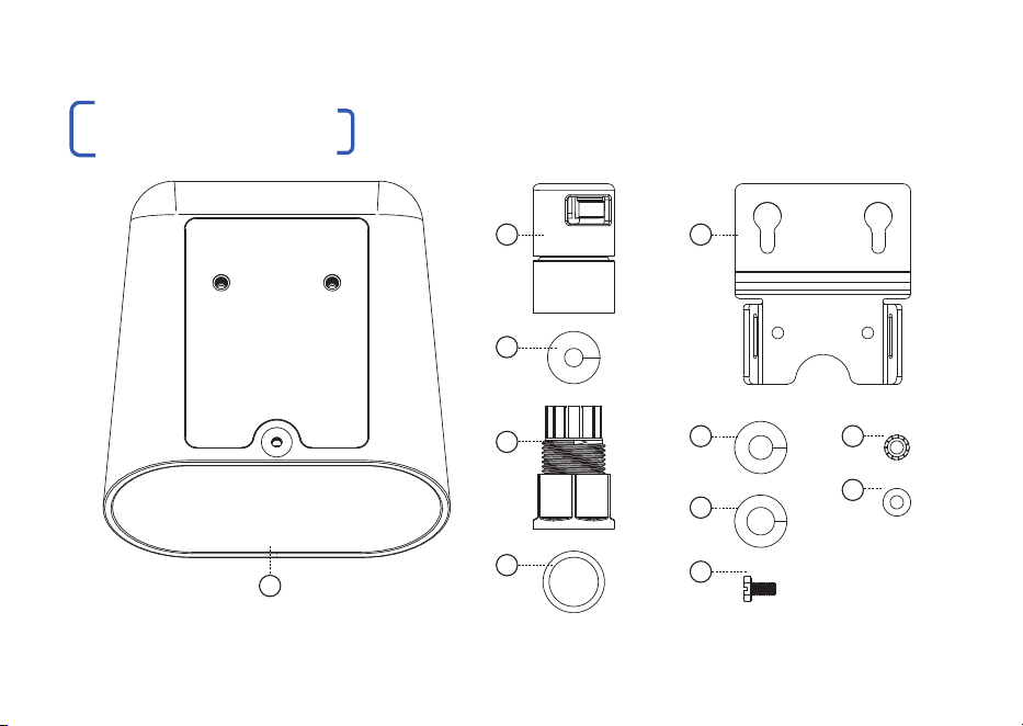
WHAT’S IN THE BOX
02 | LONGSPAN MAX XT Quickstart Guide

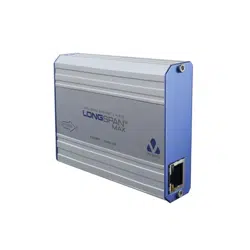
LONGSPAN Max XT Device
Enclosure: powder coated aluminium
Cable Gland Body
UV Stabilised Nylon
Cable Gland Nut (with Conduit Adaptor)
UV Stabilised Nylon
Cable Gland O-ring - Red
Pre-assembled into Cable Gland Body
Cable Gland Grommet - Black
Pre-assembled into Cable Gland Body
For 4.7 - 6.5mm cables
Cable Gland Grommet - Green
For 6.0 - 7.8mm cables
Cable Gland Grommet - Red
For 7.0 - 9.0mm cables
Mounting Plate
Anodised aluminium
Screws - Mounting & Grounding
M4 x 8mm - DIN 933SZ - Aluminium
Toothed Washer
M4 - External Toothed - Zinc Plated Steel
Nylon Washer
For use with self tapping screws
LONGSPAN Max XT Quickstart Guide
2
3
4
5
6
1
LIST OF CONTENTS
9
10
11
7
8
12
www.veracityglobal.com | 03
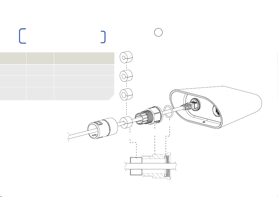
O-ring
Gland Body
Grommet
| Pass the POE cable through the
cable gland components and plug
into the RJ45 socket, ensuring that it
‘clicks’ to confirm a connection.
| To ensure an IP69K seal, the O-ring
and correctly sized Grommet must
be in place, within the Gland Body.
1
GASKET
Black
Green
Red
CABLE
4.7 - 6.5mm
6.0 - 7.8mm
7.0 - 9.0mm
EXAMPLE CABLE
Cat 5e UTP, Cat 6 UTP
Cat 5e, Cat 6 STP, Cat 6a
Double Shielded, old Cat 6a
FITTING CONNECTORS
Gland Nut
Black
Green
Red
04 | LONGSPAN MAX XT Quickstart Guide
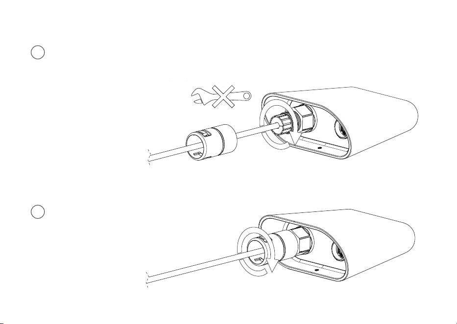
| Tighten the Cable Gland Body
onto the threaded RJ45 port.
This seals the O-ring.
Tighten the gland firmly, by hand.
Do not use tools for tightening.
2
3
| Tighten the Gland Nut onto the
Body. This seals the Grommet
around the cable.
www.veracityglobal.com | 05
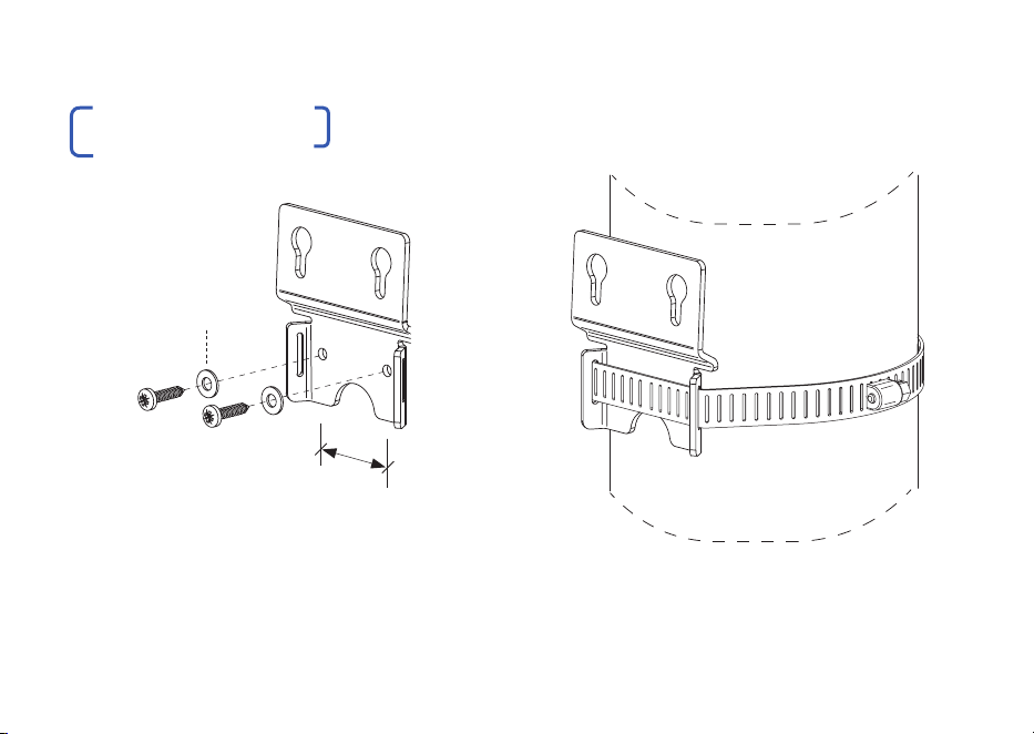
| Mounting to flat surfaces:
Maximum screw size 3.5mm (#6)
| Mounting to poles:
Maximum band width 12.5mm (1/2”)
36mm
hole centres
Use nylon washers
provided for max.
corrosion resistance
MOUNTING PLATE
06 | LONGSPAN MAX XT Quickstart Guide
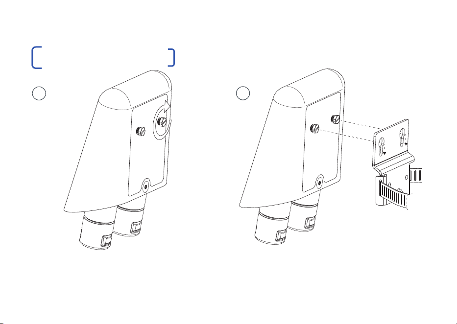
| Manually adjust the mounting screws to
allow for the mounting bracket thickness.
| Mount the device to the bracket to assess
the fit. Repeat until a tight fit is achieved. In
applications subject to vibration, use a light to
medium threadlocker on the mounting screws.
1
MOUNTING THE DEVICE
www.veracityglobal.com | 07
2
LONGSPAN Max XT should always be installed this way up.
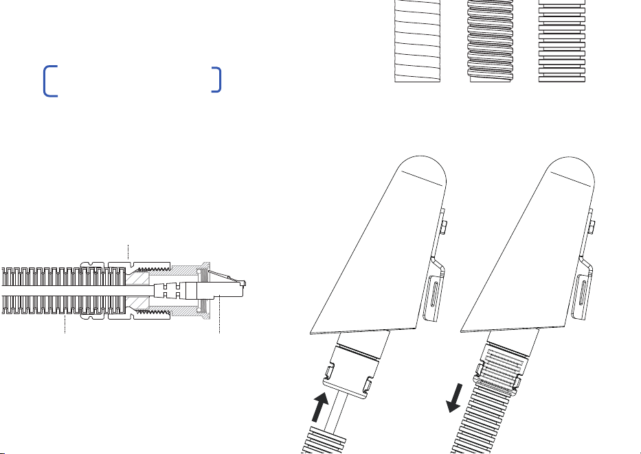
| The Conduit Adaptor section of the Cable
Gland Nut is designed for use with 20mm
(ISO) or 1/2-inch (US) flexible conduit.
| It is compatible with various types with an
outer diameter ranging 20mm - 21.5mm
Liquid Tight
Spiral
Plastic Corrugated
Flexible conduit RJ45 cable
Cable Gland Nut
(with conduit adaptor)
| With the POE cable connected to the device,
firmly push the conduit into the Conduit Adaptor
until it’s fully inserted and held securely in place.
08 | LONGSPAN MAX XT Quickstart Guide
CONDUIT ADAPTOR
www.veracityglobal.com | 09
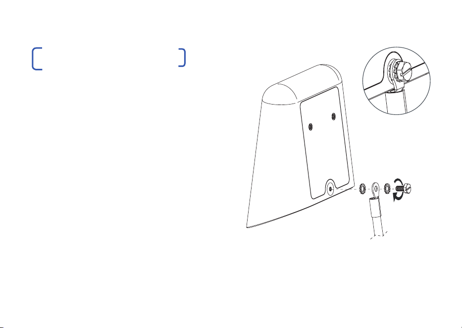
Grounding the LONGSPAN Max XT case is
generally NOT required.
Therefore the following steps can be bypassed
unless grounding is specifically required due to
local conditions or specifications.
If grounding IS required, carry out the following
steps:
| The grounding point is designed for use with
M4 ring terminals and lugs. Assemble in the
order shown.
| Always use the toothed washer to maximise
electrical connection and prevent loosening.
| Always use plated terminals. Never use bare
copper terminals.
GROUNDING THE DEVICE
| Recommendation: once assembled, cover
the grounding components in a waterproof,
dielectric grease. This will form a protective
barrier to help protect against galvanic corrosion.
10 | LONGSPAN MAX XT Quickstart Guide
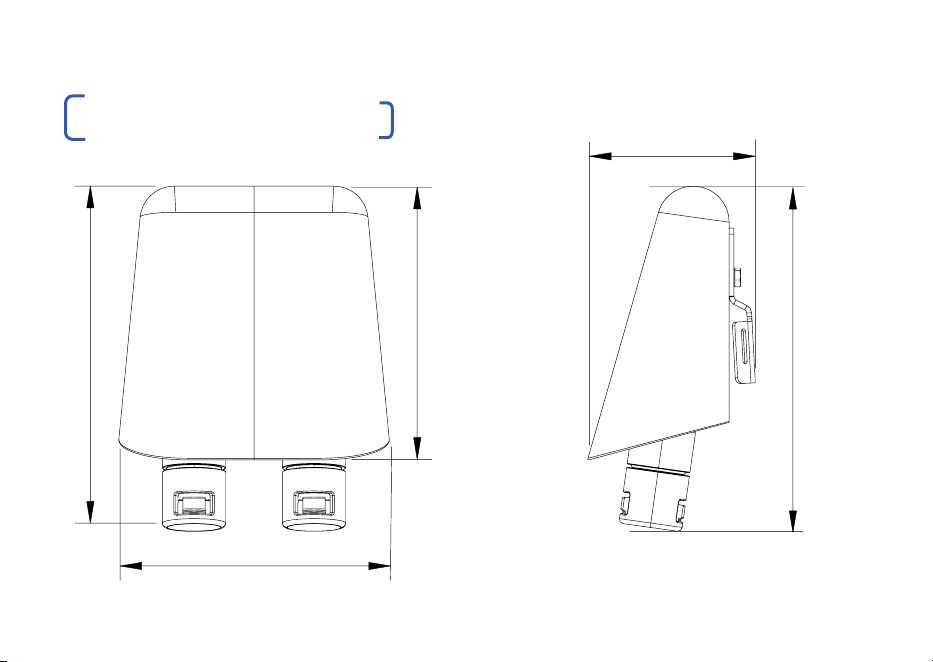
DIMENSIONAL DRAWINGS
113 mm
113 mm
144 mm
69 mm
144 mm

VLS-LSM-CXT DATA RANGE
POE DEVICE POWER
71 WATTS
62 WATTS
51 WATTS
40 WATTS
25 WATTS
Cat6
200m (656ft)
235m (770ft)
290m (950ft)
390m (1,279ft)
570m (1,870ft)
Cat5e
150m (492ft)
180m (590ft)
230m (754ft)
310m (1,017ft)
450m (1,476ft)
Cat6
820m (2,690ft)
1,050m (3,450ft)
Cat5e
690m (2,263ft)
950m (3,100ft)
CABLE TYPE
DATA RANGE 100Base-TX
DATA RANGE 10Base-T
PSE = Power Sourcing Equipment PD = Powered Device
POE
CLASS
0
1
2
3
4
5
6
7
8
POE POWER
AT PSE
15.4W
4W
7W
15.4W
30W
45W
60W
75W
90W
IEEE
STANDARD
802.3af
802.3af
802.3af
802.3af
802.3at
802.3bt
802.3bt
802.3bt
802.3bt
POE POWER
AT PD
12.95W
3.84W
6.49W
12.95W
25.5W
40W
51W
62W
71.3W
VLS-LSM-CXT POE RANGE
POE REFERENCE TABLE
www.veracityglobal.com | 11
POE Ranges are approximate
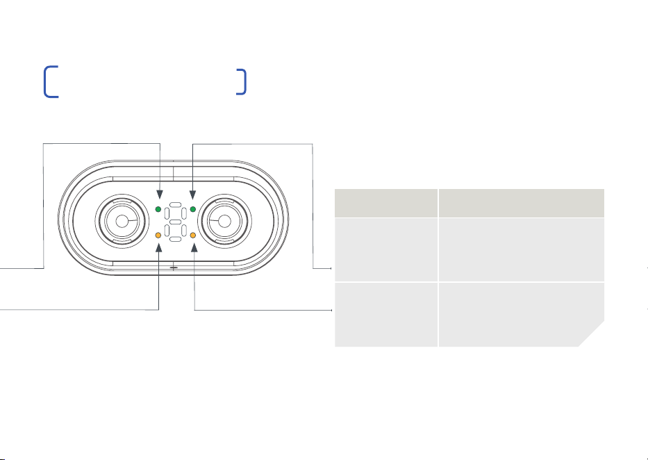
LED FUNCTION
RJ45 Green On = POE enabled
Blink = POE error
Off = POE device not
detected. Ethernet only
RJ45 Yellow On = link
Blink = activity
Ethernet and POE to Camera/Device
10Base-T/100Base-TX, auto speed, crossover,
full duplex. IEEE 802.3af/at/bt compliant.
CONNECTIONS & LEDS
COMPATIBILIT Y
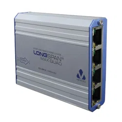
| LONGSPAN Max XT devices are compatible
with all standard LONGSPAN Base 8,
LONGSPAN Base and LONGSPAN Max
Base devices.
Details of distances, and available POE
are shown in the tables on Page 11.
POE POWER BUDGET LEDS
| The POE power budget is the measured
total available power for POE devices
powered by the LONGSPAN Max XT device.
POE power is limited by the cable type, cable
distance and power injected at the Base end.
See table for POE power vs distance.
12 | LONGSPAN MAX XT Quickstart Guide
LED FUNCTION
RJ45 Green On = 100Mbps
Flash = 10Mbps
Off = no link
RJ45 Yellow On = link
Blink = activity
LONGSPAN Link and 802.3bt POE Input
www.veracityglobal.com | 13
P
O
E
T
O
C
A
M
E
R
A
L
O
N
G
S
P
A
N
L
I
N
K
CONNECTIONS & LEDS
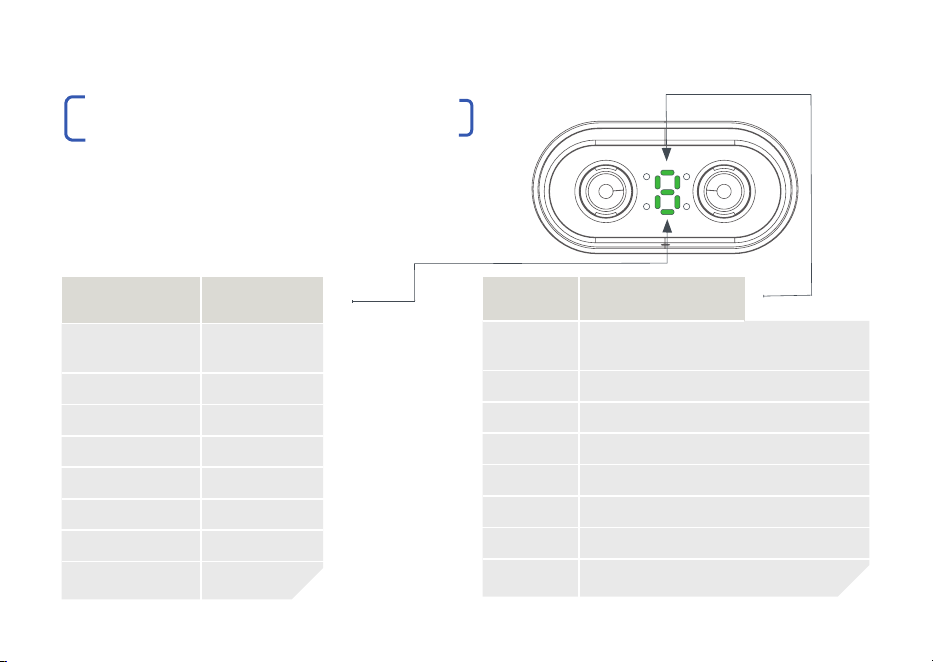
POWER & ERROR LED INDICATOR
| The 7 Segment Power and Error LED indicators
are shown here. The LED indicator for Power shows
a green ‘P’ and the Error Codes show a red ‘E’ for
2 seconds before displaying the relevant number for
2 seconds and then the code repeats.
GREEN LED POWER
P1 5W
P2 10W
P3 20W
P4 30W
P5 40W
P6 50W
P7 60W
P8 70W
RED LED ERROR CODES
E1 POE Power Draw Exceeded
E2 POE Power too Low. Voltage Disabled
E3 POE to Camera Overload
E4 POE to Camera Short
E5 POE to Camera Signature Error
E6 POE over LONGSPAN Enabled but No Link
E7 Cable Wiring Error (connection refused)
E8 Inferior Equipment (connection refused)
14 | LONGSPAN MAX XT Quickstart Guide
P
O
E
T
O
C
A
M
E
R
A
L
O
N
G
S
P
A
N
L
I
N
K
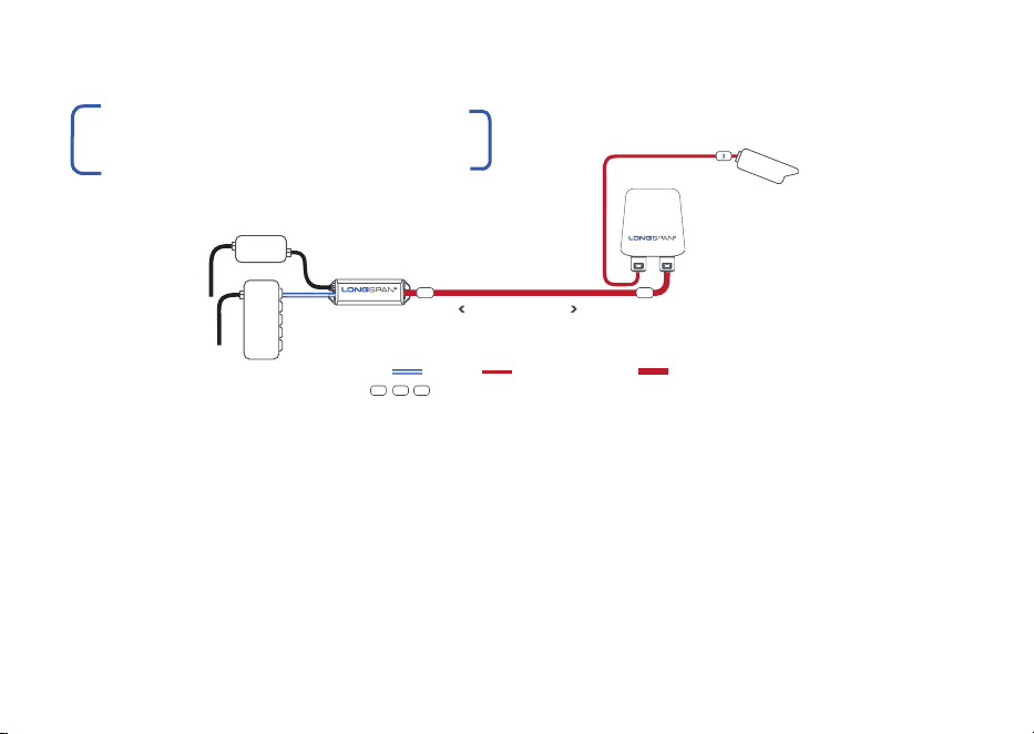
| Connect LONGSPAN Max Base to LONGSPAN
Max XT Camera and then to a POE camera, or
other POE device.
| The LONGSPAN Max Base device may be
powered either by a POE network switch
or for maximum power, by a separate Veracity
56-57V DC power supply.
| Cat6 cable is recommended for increased
POE delivery at distance.
APPLICATION DIAGRAM WITH
802.3BT POE TRANSMISSION
| The LONGSPAN Max Base device can output
a maximum of 90W POE depending upon the
optional PSU.
| See LONGSPAN Max XT Tables on Page 11 or the
datasheet tables for distance vs power levels.
| LONGSPAN Max XT will only deliver >25W POE to
802.3bt compatible IP cameras or other devices.
www.veracityglobal.com | 15
NETWORK
SWITCH
POWER
SEE POE POWER & RANGE TABLE
UP TO 820M ON CAT6
VLS-LSM-CXT
VLS-LSM-B
MAX
POWER
SUPPLY
(RECOMMENDED PSU
FOR MAXIMUM POWER)
KEY DATA ONLY POWER OVER ETHERNET LONGSPAN ETHERNET & POE
1 2 3 SURGE PROTECTION DEVICES RECOMMENDED FOR LONG OUTDOOR NETWORKS
IP CAMERA
MAX XT
VPSU-POE-100
1
2
SURGE PROTECTION
Any LONGSPAN network design for outdoor applications must incorporate
the appropriate level of surge protection to avoid invalidation of warranty due
to electrical storm damage. It is the responsibility of the system installer to
ensure the correct level of protection.
All Veracity products have been independently tested to verify their
resilience to the stringent immunity levels of international standards.
Users should note that no electronic equipment can be guaranteed to
be completely protected at levels beyond the defined standard; therefore
product warranty cannot include damage to products which has been
caused by surges exceeding those of the standards specified, for example
lightning strike activity.
It is the user’s responsibility to implement relevant surge protection
measures, as appropriate to the installation. This may include the fitting of
additional surge protection devices where required.
FCC CERTIFICATION
This device complies with Part 15 of the FCC Rules.
Operation is subject to the following two conditions: (1) this device may
not cause harmful interference, and (2) this device must accept any
interference received, including interference that may cause undesired
operation.
16 | LONGSPAN MAX XT Quickstart Guide
NOTE: This equipment has been tested and found to comply with the
limits for a Class B digital device, pursuant to Part 15 of the FCC Rules.
These limits are designed to provide reasonable protection against harmful
interference when the equipment is operated in a commercial environment.
This equipment generates, uses, and can radiate radio frequency energy
and, if not installed and used in accordance with the instruction manual,
may cause harmful interference to radio communications.
Operation of this equipment in a residential area is likely to cause harmful
interference in which case the user will be required to correct the
interference at their own expense.
Veracity UK Ltd. Prestwick International Aerospace Park,
4 Dow Road, Prestwick, KA9 2TU. UK
Veracity’s Authorised Representative in the EU (as required by
EU law for CE marked goods) is: Comply Express Unipessoal
Limitada, StartUp Madeira, EV141, Campus da Penteada, 9020
105 Funchal, Portugal.
© Veracity UK Ltd 2023 QSG DV1.6 EN
LONGSPAN Max XT
®
is a registered trademark of Veracity UK Ltd