Loading ...
Loading ...
Loading ...
9Section 3 — ASSembly & Set-Up
Set-Up
Gas and Oil Fill-Up
Service the engine with gasoline and oil as instructed in
the engine manual packed with your log splitter. Read the
instructions carefully.
WARNING! Use extreme care when handling
gasoline. Gasoline is extremely flammable and the
vapors are explosive. Never fuel the machine
indoors or while the engine is hot or running.
NOTE: Your log splitter is shipped with motor oil in the engine.
You MUST check the oil level before operating. Be careful not
to overfill. Gasoline can be added to the engine when the log
splitter is in either the horizontal or vertical position. However, it
may be easier when the splitter is in the vertical position.
Preparing the Log Splitter
1. Lubricate the beam area (where the splitting wedge will
slide) with engine oil. Do not use grease.
2. Remove the vented reservoir dipstick, which is located in
front of the engine on top of the reservoir tank. See Fig. 3-9.
NOTE: The log splitter is filled to the proper operating level
from the manufacturer with Shell Tellus® S2 M 32 Hydraulic
Fluid. However, you MUST check the fluid level before
operating. If not filled, proceed with the following steps:
CAUTION: Much of the original fluid has been
drawn into the cylinder and hoses. Make certain to
refill the reservoir to prevent damage to the
hydraulic pump.
3. Check the fluid level using the dipstick. See Fig. 3-9. Do not
overfill.
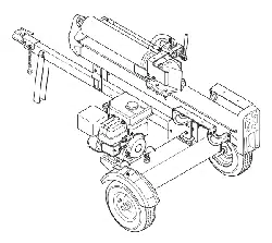
4. Carefully reposition the logsplitter off of the crate by lifting
up on the tongue tube, near the hitch coupling, and slowly
rotating the machine clockwise. See Fig. 3-7.
Repositioning the Control Handle
The control handle is shipped hanging from the valve on the
handle link.
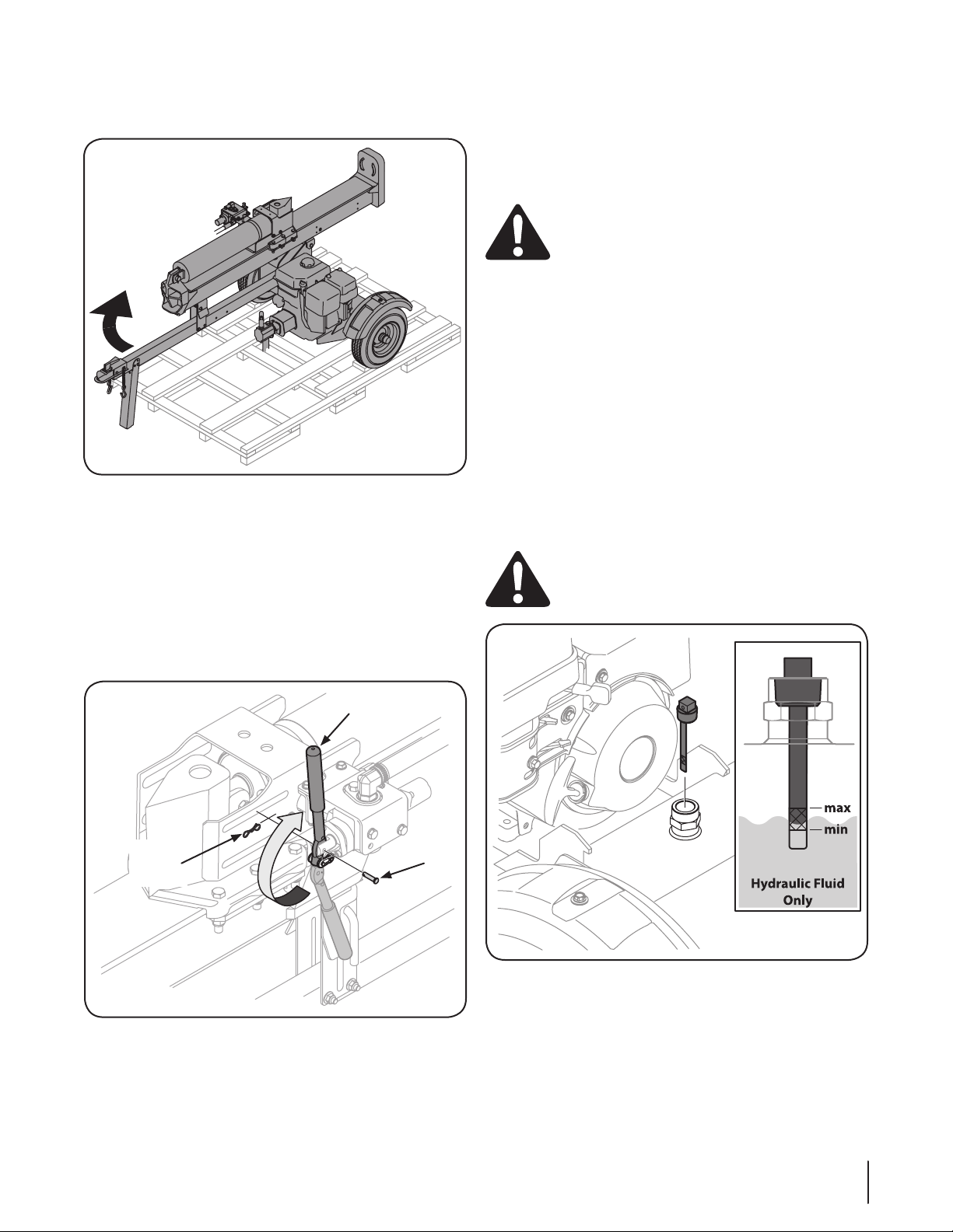
1. Remove the clevis pin and bow-tie cotter pin from the
control handle. See Fig. 3-8.
2. Rotate the control handle into the operating position and
secure with the clevis pin and bow-tie cotter pin removed
in step 1. See Fig. 3-8.
Figure 3-7
Figure 3-9
Bow-Tie
Cotter
Pin
Control Handle
Clevis
Pin
Figure 3-8
Loading ...
Loading ...
Loading ...