MODEL: LTV-WSDTH03
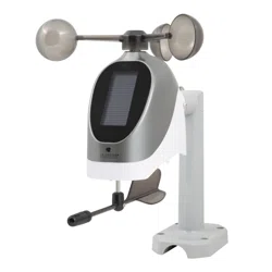
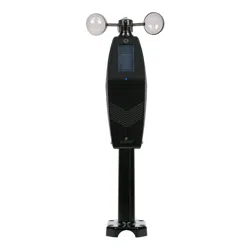
Breeze Pro Sensor
REPLACEMENT SENSOR - STATION CONNECTION
La Crosse View
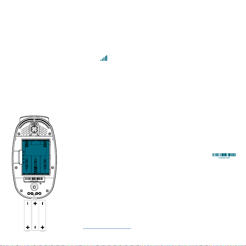
Device ID
AA
AA
AA
For users setting this up as a replacement sensor, follow these steps to
get it synced with your display:
1. Press and release the SENSOR button on your station until you see the
WIND section light up. Hold the MINUS (-) button to delete the original
sensor. The Reception Icon will begin to animate, indicating it is
searching for a new sensor connection.
2. Install 3 new AA alkaline batteries into the Breeze Pro sensor (as shown
below).
3. Keep the sensor near the display and allow 5 minutes for the sensor
readings toappear.
ADD TO THE LA CROSSE VIEW APP
1. Open your La Crosse View app, select the Devices
tab from the main menu, and then press the ADD
DEVICE or PLUS (+) button near the bottom of the
page.
2. Scan or type in the La Crosse View Device ID
located on the bottom of the sensor.
3. Give the device a Name and Location, and then press
Save. Provided you have the station connected to the
Internet, you should begin to see your sensor data in
the app within the next few minutes.
For help with adding and removing devices within the
La Crosse View app, please view our video here:
bit.ly/add_devices
3
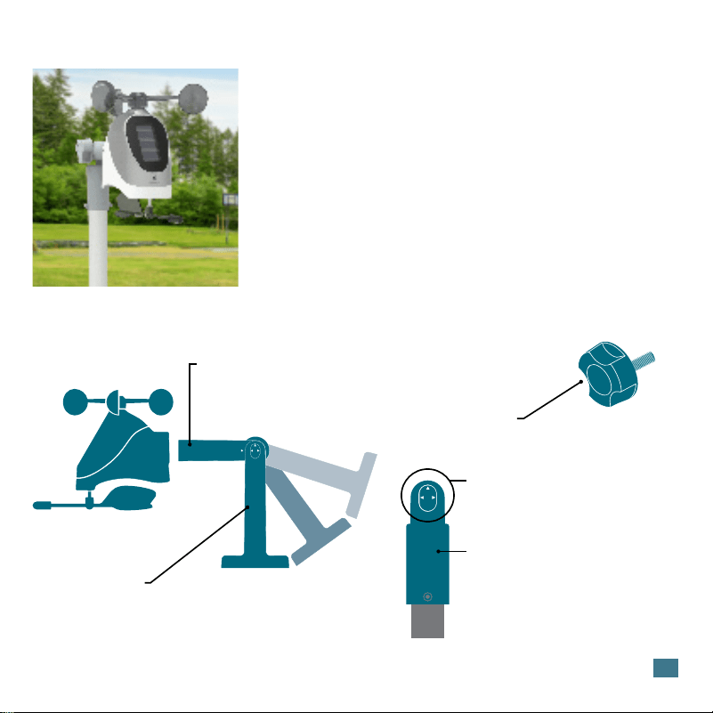
MOUNTING
For Accurate Measurements
Included Mounting Accessories
• Ensure the sensor is mounted level with the Solar Panel facing
directly to the south. This will help optimize battery life and transmit
correct wind direction readings.
• Ideally, the Breeze Pro Sensor should be mounted on the tallest
object in your area. Avoid positioning the sensor in line or below
eaves, rooflines, trees, or other objects that may obstruct wind
readings.
• Make sure all screws on the Mounting Bracket, Winds Cups,
Wind Vane, and Battery Compartment are securely fastened.
• The sensor should be mounted with the Wind Cups on top.
Mast
The horizontal conduit where the sensor
attaches. This piece will connect to either
the Adjustable Base or Pole Adapter.
Adjustable Base
The main bracket used for mounting onto flat surfaces or with
added U-bolts (not included). The grooves and Hand Screw allow
the bracket to secure to angled surfaces while still ensuring the
Mast and sensor are level.
Hand Screw
Used to lock down and secure the Mast
to the Adjustable Base or Pole Adapter.
Alignment Arrows
Provide exact 90 or 180 degree
angles when aligned with the arrow
on the Mast.
Pole Adapter
Used in place of the Adjustable Base
for mounting on top of cylindrical
conduits.
1-Inch Maximum Pole Diameter
4
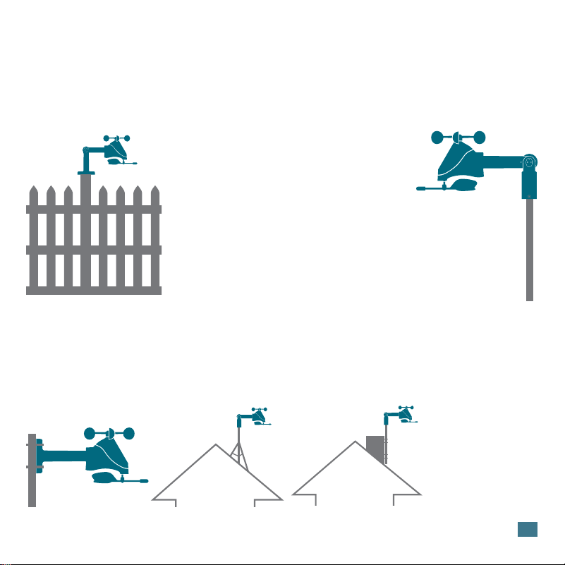
INSTALLATION OPTIONS
For Accurate Measurements
Basic Assembly
Advanced Installation Options
Fence posts, poles, decks, and even mailboxes are all common mounting options due to their convenience.
Many users prefer these types of locations as the data they provide is accurate from their ground level
perspective. However, because wind in these spots is often aected by obstructions, the readings may
dier compared to local reporting stations.
Some advanced installation options include tripods, wall mounts, eave cross mounts, chimney mounts,
and many others. Any of these can be combined with U-bolts for attachment onto a tall cylindrical conduit
using our Adjustable Base. Please note that these advanced options will require additional equipment and
possibly professional help for best results.
The illustrations above are
not to scale and are for
informative purposes only.
La Crosse Technology is not
responsible for any damages
or injury that may occur during
installation.
U-Bolt Adapters
1B Pole
Adapter
1A.
1B.
2.
3.
Mount the Adjustable Base onto a flat surface
using the four long screws provided.
Secure the Pole Adapter to a cylindrical
conduit using the two smaller screws provided.
Insert the Mast into the Breeze Pro Sensor and
tighten the provided screws on the sides.
Use the Hand Screw to attach the Mast to either the Adjustable
Base or Pole Adapter. Ensure the sensor is level, facing south,
and securely fastened at all mounting points.
1A Adjustable Base
Tripod
Setup
Chimney
Mount
5
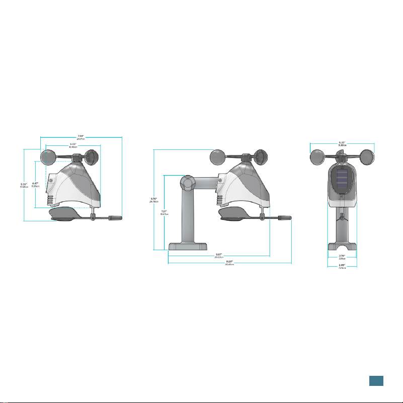
BREEZE PRO SENSOR SPECIFICATIONS (LTV-WSDTH03)
• Wind Speed Range: 0 to 111 mph (0 to 178 kMh)
• Degrees of Wind Direction: 360° with 16 Cardinal Directions
• Outdoor Temp. Range: -40°F to 140°F (-40°C to 60°C)
• Outdoor Humidity Range: 10 to 99%RH
• Transmission Range: 400 Feet (121.92 Meters)
• Power Requirements: 3 “AA” batteries
• Update Interval: Every 31 Seconds
• Sensor Dimensions: 11.97 in. L x 7.94 in. W x 9.76 in. H (30.40 cm L x 20.17 cm W x 24.79 cm H)
• Do not mix old and new batteries.
• Always purchase the correct size and grade of battery suitable for intended use.
• Ensure the batteries have with correct polarity (+/-).
• Promptly remove expired batteries.
• Do not mix Alkaline, Lithium, standard, or rechargeable batteries.
• Clean the battery contacts and also those of the device prior to battery
installation.
• Remove batteries from equipment that will not to be used for an extended period.
CARE & MAINTENANCE

6
WARRANTY INFO
La Crosse Technology Ltd. provides a 1-year limited-time warranty on this product relating to manufacturing defects in
materials & workmanship. Per the Song-Beverly Act, in the state of California, the warranty on this item becomes effective on
the date of delivery. La Crosse Technology, Ltd, 2830 S. 26th St., La Crosse, WI 54601
For Full Warranty Details, Visit: www.lacrossetechnology.com/pages/warranty
Patents: www.lacrossetechnology.com/patents
FCC STATEMENT
This equipment has been tested and found to comply with the limits for a Class B digital device, pursuant to part 15 of the FCC
Rules. These limits are designed to provide reasonable protection against harmful interference in a residential installation.
This equipment generates, uses and can radiate radio frequency energy and, if not installed and used in accordance with the
instructions, may cause harmful interference to radio communications. However, there is no guarantee that interference will
not occur in a particular installation. If this equipment does cause harmful interference to radio or television reception, which
can be determined by turning the equipment off and on, the user is encouraged to try to correct the interference by one or
more of the following measures:
• Reorient or relocate the receiving antenna.
• Increase the separation between the equipment and receiver.
• Connect the equipment into an outlet on a circuit different from that to which the receiver is connected.
• Consult the dealer or an experienced radio/TV technician for help.
This device complies with Part 15 of the FCC Rules. Operation is subject to the following two conditions:
(1) This device may not cause harmful interference, and
(2) This device must accept any interference received, including interference that may cause undesired
operation.
CAUTION!
Any changes or modifications not expressly approved by the party responsible for compliance could void the user’s authority
to operate the equipment.
All rights reserved. This manual may not be reproduced in any form, even in part, or duplicated or processed using electronic,
mechanical or chemical process without the written permission
of the publisher.
This booklet may contain errors or misprints. The information it contains is regularly checked and corrections are included
in subsequent editions. We disclaim any responsibility for any technical error or printing error, or their consequences. All
WARNING: This product can expose you to chemicals including acrylonitrile,
1, 3-butadiene, and styrene, which are known to the State of California to cause cancer and
birth defects or other reproductive harm.
For more information go to: www.P65Warnings.gov